FCC INFORMATION (U.S.A.)
|
|
|
- Marvin Johns
- 5 years ago
- Views:
Transcription


1
2 FCC INFORMATION (U.S.A.) 1. IMPORTANT NOTICE: DO NOT MODIFY THIS UNIT! This product, when installed as indicated in the instructions contained in this manual, meets FCC requirements. Modifications not expressly approved by Yamaha may void your authority, granted by the FCC, to use the product. 2. IMPORTANT: When connecting this product to accessories and/or another product use only high quality shielded cables. Cable/s supplied with this product MUST be used. Follow all installation instructions. Failure to follow instructions could void your FCC authorization to use this product in the USA. 3. NOTE: This product has been tested and found to comply with the requirements listed in FCC Regulations, Part 15 for Class B digital devices. Compliance with these requirements provides a reasonable level of assurance that your use of this product in a residential environment will not result in harmful interference with other electronic devices. This equipment generates/uses radio frequencies and, if not installed and used according to the instructions found in the users manual, may cause interference harmful to the operation of other electronic devices. Compliance with FCC regulations does not guarantee that interference will not occur in all installations. If this product is found to be the source of interference, which can be determined by turning the unit OFF and ON, please try to eliminate the problem by using one of the following measures: Relocate either this product or the device that is being affected by the interference. Utilize power outlets that are on different branch (circuit breaker or fuse) circuits or install AC line filter/s. In the case of radio or TV interference, relocate/reorient the antenna. If the antenna lead-in is 300 ohm ribbon lead, change the lead-in to co-axial type cable. If these corrective measures do not produce satisfactory results, please contact the local retailer authorized to distribute this type of product. If you can not locate the appropriate retailer, please contact Yamaha Corporation of America, Electronic Service Division, 6600 Orangethorpe Ave, Buena Park, CA90620 * This applies only to products distributed by YAMAHA CORPORATION OF AMERICA. ADVARSEL! Lithiumbatteri Eksplosionsfare ved fejlagtig håndtering. Udskiftning må kun ske med batteri af samme fabrikat og type. Levér det brugte batteri tilbage til leverandoren. VARNING Explosionsfara vid felaktigt batteribyte. Använd samma batterityp eller en ekvivalent typ som rekommenderas av apparattillverkaren. Kassera använt batteri enlight fabrikantens instruktion. VAROITUS Paristo voi räjähtää, jos se on virheellisesti asennettu. Vaihda paristo ainoastaan laitevalmistajan suosittelemaan tyyppiin. Hävitä käytetty paristo valmistajan ohjeiden mukaisesti. NEDERLAND / THE NETHERLANDS Dit apparaat bevat een lithium batterij voor geheugen back-up. This apparatus contains a lithium battery for memory back-up. Raadpleeg uw leverancier over de verwijdering van de batterij op het moment dat u het apparaat ann het einde van de levensduur afdankt of de volgende Yamaha Service Afdeiing: Yamaha Music Nederland Service Afdeiing Kanaalweg 18-G, 3526 KL UTRECHT Tel For the removal of the battery at the moment of the disposal at the end of the service life please consult your retailer or Yamaha Service Center as follows: Yamaha Music Nederland Service Center Address: Kanaalweg 18-G, 3526 KL UTRECHT Tel : Gooi de batterij niet weg, maar lever hem in als KCA. Do not throw away the battery. Instead, hand it in as small chemical waste.
3 SPECIAL MESSAGE SECTION This product utilizes batteries or an external power supply (adapter). DO NOT connect this product to any power supply or adapter other than one described in the manual, on the name plate, or specifically recommended by Yamaha. WARNING: Do not place this product in a position where anyone could walk on, trip over,or roll anything over power or connecting cords of any kind. The use of an extension cord is not recommended! IF you must use an extension cord, the minimum wire size for a 25' cord (or less ) is 18 AWG. NOTE: The smaller the AWG number,the larger the current handling capacity. For longer extension cords, consult a local electrician. This product should be used only with the components supplied or; a cart, rack, or stand that is recommended by Yamaha. If a cart, etc., is used, please observe all safety markings and instructions that accompany the accessory product. SPECIFICATIONS SUBJECT TO CHANGE: The information contained in this manual is believed to be correct at the time of printing. However, Yamaha reserves the right to change or modify any of the specifications without notice or obligation to update existing units. This product, either alone or in combination with an amplifier and headphones or speaker/s, may be capable of producing sound levels that could cause permanent hearing loss. DO NOT operate for long periods of time at a high volume level or at a level that is uncomfortable. If you experience any hearing loss or ringing in the ears, you should consult an audiologist. IMPORTANT: The louder the sound, the shorter the time period before damage occurs. Some Yamaha products may have benches and / or accessory mounting fixtures that are either supplied with the product or as optional accessories. Some of these items are designed to be dealer assembled or installed. Please make sure that benches are stable and any optional fixtures (where applicable) are well secured BEFORE using. Benches supplied by Yamaha are designed for seating only. No other uses are recommended. Battery Notice: This product MAY contain a small non-rechargeable battery which (if applicable) is soldered in place. The average life span of this type of battery is approximately five years. When replacement becomes necessary, contact a qualified service representative to perform the replacement. This product may also use household type batteries. Some of these may be rechargeable. Make sure that the battery being charged is a rechargeable type and that the charger is intended for the battery being charged. When installing batteries, do not mix batteries with new, or with batteries of a different type. Batteries MUST be installed correctly. Mismatches or incorrect installation may result in overheating and battery case rupture. Warning: Do not attempt to disassemble, or incinerate any battery. Keep all batteries away from children. Dispose of used batteries promptly and as regulated by the laws in your area. Note: Check with any retailer of household type batteries in your area for battery disposal information. Disposal Notice: Should this product become damaged beyond repair, or for some reason its useful life is considered to be at an end, please observe all local, state, and federal regulations that relate to the disposal of products that contain lead, batteries, plastics, etc. If your dealer is unable to assist you, please contact Yamaha directly. NAME PLATE LOCATION: The name plate is located on the bottom of the product. The model number, serial number, power requirements, etc., are located on this plate. You should record the model number, serial number, and the date of purchase in the spaces provided below and retain this manual as a permanent record of your purchase. NOTICE: Service charges incurred due to a lack of knowledge relating to how a function or effect works (when the unit is operating as designed) are not covered by the manufacturer s warranty, and are therefore the owners responsibility. Please study this manual carefully and consult your dealer before requesting service. ENVIRONMENTAL ISSUES: Yamaha strives to produce products that are both user safe and environmentally friendly. We sincerely believe that our products and the production methods used to produce them, meet these goals. In keeping with both the letter and the spirit of the law, we want you to be aware of the following: Model Serial No. Purchase Date PLEASE KEEP THIS MANUAL 92-BP 3
4 WARNING PRECAUTIONS PLEASE READ CAREFULLY BEFORE PROCEEDING * Please keep these precautions in a safe place for future reference. Always follow the basic precautions listed below to avoid the possibility of serious injury or even death from electrical shock, short-circuiting, damages, fire or other hazards. These precautions include, but are not limited to, the following: Do not open the instrument or attempt to disassemble the internal parts or modify them in any way. The instrument contains no user-serviceable parts. If it should appear to be malfunctioning, discontinue use immediately and have it inspected by qualified Yamaha service personnel. Do not expose the instrument to rain, use it near water or in damp or wet conditions, or place containers on it containing liquids which might spill into any openings. If the AC adaptor cord or plug becomes frayed or damaged, or if there is a sudden loss of sound during use of the instrument, or if any unusual smells or smoke should appear to be caused by it, immediately turn off the power switch, disconnect the adaptor plug from the outlet, and have the instrument inspected by qualified Yamaha service personnel. Use the specified adaptor (PA-5C or an equivalent recommended by Yamaha) only. Using the wrong adaptor can result in damage to the instrument or overheating. Before cleaning the instrument, always remove the electric plug from the outlet. Never insert or remove an electric plug with wet hands. Check the electric plug periodically and remove any dirt or dust which may have accumulated on it. CAUTION Always follow the basic precautions listed below to avoid the possibility of physical injury to you or others, or damage to the instrument or other property. These precautions include, but are not limited to, the following: Do not place the AC adaptor cord near heat sources such as heaters or radiators, and do not excessively bend or otherwise damage the cord, place heavy objects on it, or place it in a position where anyone could walk on, trip over, or roll anything over it. When removing the electric plug from the instrument or an outlet, always hold the plug itself and not the cord. Do not connect the instrument to an electrical outlet using a multipleconnector. Doing so can result in lower sound quality, or possibly cause overheating in the outlet. Unplug the AC power adaptor when not using the instrument, or during electrical storms. Before connecting the instrument to other electronic components, turn off the power for all components. Before turning the power on or off for all components, set all volume levels to minimum. Do not expose the instrument to excessive dust or vibrations, or extreme cold or heat (such as in direct sunlight, near a heater, or in a car during the day) to prevent the possibility of panel disfiguration or damage to the internal components. Do not use the instrument near other electrical products such as televisions, radios, or speakers, since this might cause interference which can affect proper operation of the other products. Do not place the instrument in an unstable position where it might accidentally fall over. Before moving the instrument, remove all connected adaptor and other cables. When cleaning the instrument, use a soft, dry cloth. Do not use paint thinners, solvents, cleaning fluids, or chemical-impregnated wiping cloths. Also, do not place vinyl, plastic or rubber objects on the instrument, since this might discolor the panel or keyboard. Do not rest your weight on, or place heavy objects on the instrument, and do not use excessive force on the buttons, switches or connectors. Do not operate the instrument for a long period of time at a high or uncomfortable volume level, since this can cause permanent hearing loss. If you experience any hearing loss or ringing in the ears, consult a physician. REPLACING THE BACKUP BATTERY This instrument contains a non rechargeable internal backup battery which permits internal data to remain stored even when the power is off. When the backup battery needs replacing, the message "Backup Battery Low" will display in the display. When this happens, immediately back up your data, then have qualified Yamaha service personnel replace the backup battery. Do not attempt to replace the backup battery yourself, in order to prevent the possible serious hazards. Always have qualified Yamaha service personnel replace the backup battery. Never place the backup battery in a location that a child can reach, since a child might accidentally swallow the battery. If this should happen, consult a physician immediately. SAVING USER DATA Always save data to a floppy disk frequently, in order to help prevent the loss of important data due to a malfunction or user operating error. Yamaha cannot be held responsible for damage caused by improper use or modifications to the instrument, or data that is lost or destroyed. Always turn the power off when the instrument is not in use. (3)-3
5 How to use the manuals/printing conventions in this manual Owner s Manual Introduction Thank you for choosing a Yamaha RM1x Sequence Remixer. The RM1x is a complete dance-music workstation that can be used both as a real-time performance instrument and a powerful production tool. Its intuitive interface makes real-time operation easy for artists with a DJ background, while in-depth sequencing and editing functions make it possible to create sophisticated original patterns and songs from scratch. In addition to powerful sequence recording and playback capability, the RM1x also features a great sounding tone generator built in so you don t need any extra equipment. You can even edit the voices to create sounds that are perfectly suited to your music. Keep this Owner s Manual handy while familiarizing yourself with the RM1x, and store it in a safe place for later reference. 5
6 Main Features Main Features The sequencer of the RM1x provides 16 sequence tracks and up to 110,000 notes of storage capacity for professional-level sequencing power. Note timing resolution is 1/480th of a quarter note. Memory is backed up, so your data will not disappear when the power is turned off. Easy operation with the large 64 x 240 dot display. Intuitive performance control with 8 assignable real-time control knobs, 4 display knobs, and a large multi-function keyboard. An awesome assortment of preset patterns means you can play right away without having to program. Easy programming via an advanced interface that allows a wide range of parameters to be accessed and edited when you need to be in total control of your sound. Powerful sequencing capabilities with in-depth editing function make it possible to create even complex patterns and musical textures. Assemble grooves in real time in the Pattern mode: each of the Pattern mode s styles has up to 16 sections which can be directly switched in real time during playback via the RM1x keyboard. Advanced tone generator technology gives you a extensive arsenal of outstanding sounds built in. Edit and refine the RM1x voices to create sounds that most ideally suit your own music. A sophisticated multi-effect system can be used to add anything from subtle ambiance to wild variations. Tap BPM entry lets you define tempos the way you feel them rather than with numbers. Full MIDI compatibility means that the RM1x can be used as the core of a larger music production system. 6 RM1x SEQUENCE REMIXER
7 How to use the manuals The documentation for the RM1x consists of the following two manuals. Understand the role of each manual, and refer to them as necessary. Owner's Manual (this manual) This explains precautions for use, how to make connections, and all parameters and commands. Use this manual like a dictionary whenever you need to. Chapter 1. Basic concepts Chapter 2. Pattern mode Chapter 3. Pattern Chain mode Chapter 4. Song mode Chapter 5. Utility mode How to use the manuals/printing conventions in this manual Pattern mode, Pattern chain mode and Song mode have several functions in common. In this manual, explanations for these common functions are given in greater detail in chapter 2 Pattern mode. Some of the overlapping explanation in chapter 3 Pattern Chain mode and chapter 4 Song mode is omitted. In such cases, the appropriate page of chapter 2 Pattern mode is indicated so that you can refer to it. List Book This is a booklet that contains various lists such as the Voice list, Preset Style list, Effect list, MIDI data format, and MIDI implementation chart. Printing conventions in this manual This manual uses the following icons to indicate buttons and to distinguish different types of information. p This indicates a panel button. The symbol in the box indicates the symbol printed on the button. 1 2 This indicates the actual procedure for using the function. n This indicates supplementary explanations related to the function, examples of use, and hints. RM1x SEQUENCE REMIXER 7
8 Finding the information that you need Finding the information that you need In order to find the information that you need, you can make use of the following pages. Table of contents (page 9) Locate the desired information within the flow of the entire manual. Front and rear panels (page 11) Here you can read about the name and location of each button and control, and read about their function. Quickstart Guide (page20) This brief, easy-to-follow section shows you how to use the basic features and functions of your new RM1x. Function tree (page 32) This lets you locate the desired information within the structure of the command hierarchy. Glossary (page 146) This section contains unfamiliar terms or phrases in alphabetical order with their explanations. Index (page 150) This lets you search alphabetically for unfamiliar terms to find pages on which they are discussed and pages on which related topics appear. 8 RM1x SEQUENCE REMIXER
9 Table of Contents SETUP 1. Front and rear panels...11 Front Panel...11 Rear Panel...14 Floppy disk drive Connections Power supply connections...16 Audio equipment connections...17 Connecting a footswitch...18 Connecting external MIDI devices...18 Connecting a MTR (multi-track recorder) Quickstart Guide Using the included disk...22 BASIC OPERATION Chapter 1. BASIC CONCEPTS 1. Function tree How the RM1x is organized Sequencer block Tone generator block Controller block Effect block About floppy disks...42 Chapter 2. PATTERN MODE 1. PATTERN Playback Recording Groove Play FX MIDI delay Arpeggio Voice Voice Edit Effect Setup Disk Job Edit Split Chapter 3. PATTERN CHAIN MODE 1. Pattern Chain Playback Disk Job Chapter 4. SONG MODE 1. SONG Playback Recording Groove Play FX MIDI delay Arpeggio Voice Voice Edit RM1x SEQUENCE REMIXER 9
10 Table of Contents 9. Effect Setup Disk Job Edit Split (Song to Pattern) Chapter 5. UTILITY MODE 1. System MIDI Setup MIDI Filter Appendix 1. Specifications Troubleshooting Error Messages Glossary Index The illustrations and LCD screens as shown in this owner s manual are for instructional purposes only, and may be different from the ones on your RM1x. 10 RM1x SEQUENCE REMIXER
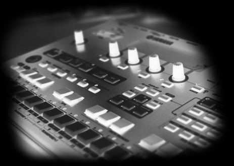
11 SETUP 1. Front and rear panels Front Panel SETUP BPM Display Normally this 4-digit LED numeric display shows the current BPM (Beats Per Minute) value, right down to a tenth of a beat. It can be switched to display measure numbers rather than beats per minute via a utility function (page 133). The BPM display also shows values related to the real time Controller Knobs (page 12), but only while any of the knobs are operated. 2. MIDI Data Monitors The MIDI IN and OUT indicators above the BPM display light whenever MIDI data is received via the rear-panel MIDI IN connector (red MIDI IN indicator), or when MIDI data is transmitted by the RM1x via the MIDI OUT connector (green MIDI OUT indicator). 3. LCD Display The RM1x's large backlit LCD display panel displays the parameters and values related to the currently selected operation or mode. The Display Knobs (page 12) and Function Buttons located immediately below the LCD display directly affect the corresponding parameters or functions on the display. The [DISPLAY] and [CURSOR] buttons are also closely related to display operation, and details are provided in the Basic Operation section beginning on page 23. A CONTRAST control for the LCD display is provided on the rear panel (page 14). The LCD display can be set for normal or inverse (white on black) display via a utility mode function (page 133). RM1x SEQUENCE REMIXER 11
12 SETUP 4. Display Knobs The four knobs located immediately below the LCD display directly control the corresponding parameters on the display. For example, in the main PATTERN mode Display Knob 1 can be used to select a style, and Display Knob 4 can be used to set the BPM. More details are provided in the Basic Operation section beginning on page Function Buttons and Indicators The function buttons - [F1] through [F4] - are similar to the Display Knobs in that they directly control the corresponding functions on the LCD display, but only when the related indicator is lit. More details are provided in the Basic Operation section beginning on page VOLUME Control Adjusts the volume of the RM1x audio output via the rear-panel OUTPUT and PHONES jacks. 7. Real Time Controller Knobs & [KNOB] Button These knobs allow the corresponding parameters to be controlled in real time during pattern or song playback. The parameters listed on the panel below the knobs are the default pre-assigned parameters, but other parameters can be assigned as required via the SETUP submode KNOB ASSIGN function (page 74). The knobs can be switched to control one of two different parameter groups - A and B - via the [KNOB] button. The A parameter group (the upper default parameters listed on the panel) are selected when the [KNOB] indicator is lit, and the B group (the lower parameters) is selected when the [KNOB] indicator is out. Different parameters can be assigned to both the A and B groups via the KNOB ASSIGN function mentioned above. 8. Cursor Buttons The cursor buttons move the cursor around the LCD display screen, highlighting the various parameters that are available for editing (the RM1x cursor appears as a dark block with inverse characters). 9. [NO -1] and [YES +1] Buttons The [NO -1] and [YES +1] buttons are used to edit (change the value of) the parameter at which the cursor is currently located. The [NO -1] button decrements (decreases stepwise) the value of the selected parameter, while the [YES +1] button increments (increases stepwise) the parameter. Press either button briefly to decrement or increment the parameter by one, or hold the button for continuous decrementing of incrementing in the specified direction. The [NO -1] and [YES +1] button are also used to respond to certain prompts when they appear. Press [YES +1] to go ahead with the operation, or [NO -1] to cancel. 10. DISPLAY [<-] and [->] Buttons When the selected mode or submode (page 23) includes more parameters than can fit on the display at one time, arrow symbols will appear at the left and/or right side of the display to indicate that more parameters are available in the indicated direction(s). The DISPLAY [<-] and [->] buttons can be used to scroll the display in the corresponding direction when this occurs. 11. MODE and SUBMODE Buttons The four MODE buttons select the main RM1x operating modes (PATTERN, PATTERN CHAIN, SONG, and UTILITY), while the SUBMODE buttons select a range of submodes via which you can access the RM1x's detailed programming features. Details on mode and submode selection are provided in the Basic Operation section beginning on page RM1x SEQUENCE REMIXER
13 SETUP 12. [EXIT] Button The [EXIT] button takes you out of any function selected by the function buttons, or the edit or job modes (described below), directly back to the current main mode (e.g. SONG or PATTERN). 13. Sequencer Buttons and Indicators The sequencer buttons control recording and playback in the PATTERN, PATTERN CHAIN, and SONG modes. REC e PLAY p STOP s r & f t Activates the record-ready mode in the RM1x PATTERN and SONG modes. The red REC button indicator will light, then recording will begin as soon as the p button is pressed. The e button can be pressed again to cancel the record-ready mode before recording is actually started by pressing the p button. Starts playback from the current point in the pattern or song if the record-ready mode is not active, or recording from the same point if the record-ready mode is active. The green PLAY indicator flashes at the current BPM during recording and playback. Stops playback or recording. Fast reverse and forward. Press the r or f button to rapidly move through the pattern or song in the corresponding direction. Top. Instantly returns to the first beginning of the current song or pattern (i.e. the first beat of the first measure). 14. Keyboard This 26-note keyboard makes it possible to program the RM1x without having to connect an external MIDI keyboard. It's even polyphonic, so you can directly enter chords as well as single notes. The only thing it lacks is velocity sensitivity. The RM1x does, however, accept velocity information from an external MIDI keyboard. The keyboard also performs a range of functions as specified by the keyboard mode button (below): track selection, transposition, numeric data entry, track mute/solo, and section selection. The black keys also perform a range of other functions, such as selecting specific track ranges and memorizing a number of track mute setups. 15. Keyboard Mode Buttons These buttons modify the function of the RM1x keyboard for track selection, transposition, numeric data entry, track mute/ solo, and section selection. Details are provided in the Basic Operation section beginning on page [OCT DOWN] and [OCT UP] Buttons Although the range of the RM1x keyboard is a little over two octaves, the [OCT DOWN] and [OCT UP] buttons allow the pitch of the keyboard to be shifted down or up in octave steps, over a range of 8 (+/- 4) octaves. Each time the [OCT DOWN] button is pressed the pitch of the keyboard is shifted down by one octave, until the lower limit is reached. The [OCT UP] button shifts the pitch of the keyboard up in the same way. The current amount of octave shift is indicated on the LCD display. 17. [SHIFT] Button The [SHIFT] button is used to access several secondary or background functions that you might only need in special situations. For example, the [SHIFT] button can be used when you want to solo a track instead of muting it via the [MUTE] keyboard mode button. The [SHIFT] button can also be used in conjunction with the Display Knobs: hold the [SHIFT] button while rotating a knob for faster data selection. 18. [ARPEGGIO ON] Button Turns the RM1x's automatic arpeggio feature on or off (page 62). The [ARPEGGIO ON] button indicator will light when the ARPEGGIO feature is on. 19. [TAP/ENTER] Button This dual-purpose button is used both for tap-entry of BPM values (page 20), and to enter numeric values (page 26). RM1x SEQUENCE REMIXER 13
14 SETUP Rear Panel STANDBY/ON Switch Press in to turn the RM1x on, and press again to turn it off. When the power is on one of the mode button indicators will light and the PATTERN mode display will appear on the LCD (Liquid Crystal Display). 2. DC IN Jack The DC output cable from the Yamaha PA-5C AC Power Adaptor supplied with the RM1x is plugged in here. 3. CONTRAST Control Use the CONTRAST control to achieve the best LCD display visibility (LCD visibility varies greatly with viewing angle). 4. MIDI IN & OUT Connectors The RM1x has MIDI IN and MIDI OUT connectors for maximum system flexibility. If you plan to use a MIDI keyboard or other instrument to play and program the RM1x, it should be connected to the RM1x MIDI IN connector (see Connecting external MIDI devices, page 18). Input filters defining what data will and will not be received by the MIDI IN connector can be set as required via the UTILITY mode (page 137). The MIDI OUT connector can be connected to an external tone generator or synthesizer if you want to drive external voices from the RM1x sequencer. Like the MIDI IN connector, MIDI filters can be set for the MIDI OUT connector via the UTILITY mode. 5. L/MONO & R OUTPUT Jacks These are the main stereo outputs from the RM1x tone generator system (see Audio equipment connections, page 17). Both are standard 1/4 mono phone plugs. When a plug is inserted into only the L/MONO output, the left- and rightchannels signals are mixed and delivered via that output to allow direct connection to mono sound systems. The output level is adjusted via the VOLUME control (page 12). 6. PHONES Jack Any pair of stereo headphones with a 1/4 stereo phone plug can be plugged in here for convenient monitoring. The PHONES output level is adjusted via the VOLUME control. 7. FOOT SW Jack An optional Yamaha FC4 or FC5 footswitch connected to this jack can be used for start/stop, section selection, sustain, or tap BPM entry, as determined by the setting of the UTILITY mode FOOT SWITCH parameter (page 132). 14 RM1x SEQUENCE REMIXER
15 Floppy disk drive 1. Floppy disk slot This is where floppy disks are inserted for loading or saving data. 3.5 inch 2HD (MF2HD) or 2DD (MF2DD) floppy disks can be used. (page 42) 2. Disk-in-use indicator This indicator will light while data is being read from or written to the floppy disk. Never attempt to remove the disk while this indicator is lit. 3. Eject button Press this button to remove the floppy disk. Disks must be inserted or removed gently and firmly, and only while the access indicator is dark. SETUP 2. Disk-in-use indicator 3. Eject button 1. Floppy disk slot n The back of a floppy disk contains a write protect tab as shown in the following illustration. When this tab is in the downward position (with the window open), it will not be possible to modify, add, or delete data. When you wish to protect important data, you should leave the tab in this position. Write permit Write prohibit Write protect tab CAUTION! Be aware that Yamaha can make no guarantee regarding data damage that results from improper use. RM1x SEQUENCE REMIXER 15
16 SETUP 2. Connections In order to use the RM1x, the included AC adaptor and an amp system etc. must be connected. If you use external MIDI devices or controllers, these must also be connected. This sections explains how to make these connections. CAUTION! Be sure to turn off the STANDBY/ON switch before making any connections. If you make connections while the STANDBY/ON switch is on, you risk damaging external equipment such as the amp or speakers. Power supply connections 1 Make sure that the STANDBY/ON switch of the RM1x is set to STANDBY, and connect the included AC adaptor (PA-5C) to the power supply jack. Wrap the DC output cable of the adaptor around the cable clip (as shown below) to prevent accidental unplugging of the cable during operation. 2 Plug the AC adaptor into an AC outlet, and turn on the RM1x STANDBY/ON switch. When turning the power off, simply reverse the procedure. WARNING! Use only the included PA-5C AC adaptor (or other adaptor specifically recommended by Yamaha). Using other AC adaptors will cause malfunctions. Also, be sure to unplug the AC adaptor from the AC outlet if you will not be using the RM1x. CAUTION! Even when the switch is in the STANDBY position, electricity is still flowing to the instrument at the minimum level. When you are not using the RM1x for a long time, make sure you unplug the AC power adaptor from the wall AC outlet. Never interrupt the power supply (e.g. unplug the AC adaptor) during any RM1x record operation! Doing so can result in a loss of data. 16 RM1x SEQUENCE REMIXER
17 PAD 26dB dB 26dB UTILITY MIDI SETUP VIEW DYNAMICS EQ/ATT Ø/DELAY FADER MODE EFFECT 1 EFFECT 2 OPTION I/O REMOTE AUX 1 HOME 17 SEL SOLO ON GAIN PAN/ ROUTING AUX 2 AUX 3 AUX 4 18 SEL SOLO ON SEL SOLO ON SEL SOLO ON 26dB PHANTOM +48V OFF ON PHANTOM +48V INPUT (BAL) 21 SEL SOLO 26dB FUNCTION MEMORY 22 SEL SOLO 26dB 23 SEL SOLO 1 RETURN ON ON ON dB 24 SEL SOLO ON SEL SOLO ON 26dB SEL SOLO ON 26dB SEL SOLO ON dB SEL SOLO ON dB SEL SOLO ON 60 PAN F G dB 15/16 2TR IN 10dBV (UNBAL) L R IN OUT 2TR MONITOR 2TR IN PHONES GAIN GAIN GAIN LEVEL LEVEL SEL SOLO ON OFF ON DIGITAL MIXING CONSOLE PAN F G MASTER SEL ON MASTER EQ HIGH HI-MID LO-MID LOW SELECTED CHANNEL 1 RETURN 2 SEL SEL SOLO ON 1/DEC ENTER VOL SOLO ON PARAMETER L STEREO R CLIP SOLO MEMORY +1/INC CURSOR SETUP Audio equipment connections To output the sound of the RM1x, connect an amp or mixer to the output jacks. Connection to powered speakers Connect two powered speakers (left and right) to the output jacks (L/MONO, R). If you are connecting only one powered speaker, use the L/MONO jack. Connection to a mixer Connect the output jacks (L/MONO, R) to two channels of the mixer. The channel connected to the L/MONO jack should be panned left, and the channel connected to the R jack should be panned right. Make the same type of connections if you are connecting the RM1x to an MTR or cassette deck GAIN +10 GAIN GAIN GAIN GAIN GAIN GAIN GAIN GAIN GAIN MONITOR 13/14 15/16 OUT PHONES /14 15/16 STEREO /14 15/16 STEREO Using headphones If you are using headphones, connect them to the rear panel PHONES (headphones) jack. When using headphones, adjust the volume to an appropriate level that will not harm your hearing. CAUTION! Do not connect the output jacks of the RM1x to the mic input jacks of an amp or cassette deck etc. If they are connected to mic inputs, the sound quality may be impaired, and the device may be damaged. Also, when connecting the RM1x to a mixer or similar device, set the mixer channels to the Line Input position. RM1x SEQUENCE REMIXER 17
18 SETUP Connecting a footswitch When using a separately sold FC4 or FC5 foot switch, insert the foot switch plug into the FOOT SW jack located on the rear panel. FC4 or FC5 Connecting external MIDI devices Connecting a MIDI keyboard Realtime recording input will be easier if you use a MIDI keyboard. Use a MIDI cable to connect the MIDI OUT of the external MIDI keyboard to the MIDI IN connector on the rear panel. MIDI OUT Connecting a tone generator module RM1x song and pattern playback data can be used to play an external tone generator module. Use a MIDI cable to connect the MIDI OUT connector on the rear panel to the MIDI IN connector of the external MIDI device. MIDI IN 18 RM1x SEQUENCE REMIXER
19 Connecting a MTR (multi-track recorder) Since the RM1x implements MTC (MIDI Time Code) and MMC (MIDI Machine Control), you can produce music while synchronized to a MTC- or MMC-compatible multi-track recorder. Use MIDI cables to connect the MIDI OUT connector of the RM1x to the MIDI IN connector of the MTR, and the MIDI IN connector of the RM1x to the MIDI OUT connector of the MTR. If you use MTC or MMC to control an MTR, set the Utility mode MIDI page MIDI Sync setting to MTC." SETUP Synchronizing the RM1x by MTC from an external device MIDI IN MIDI OUT MTR (MTC,MMC-compatible) Controlling an external device via MMC from the RM1x MIDI OUT MTR (MTC,MMC-compatible) MIDI IN RM1x SEQUENCE REMIXER 19
20 SETUP 3. Quickstart Guide When your RM1x is properly connected and powered up, try the following to get a feel for how easy it is to remix the preset patterns to create your own groove. But remember, this is just the tip- of the iceberg! The RM1x can do much, much more. 1. Select a Style Use Display Knob 1 to select a preset style (P01 P60). 4. Dial In a New BPM (Beat Per Minute) Use Display Knob 4 to adjust the BPM to a value that feels right to you. 2. Start Playback Press the PLAY p button. The currently selected section of the selected style will begin playing. This pattern will continue to loop until a different section or style is selected. 5. Tap In a New BPM Tap on the [TAP] button a few times at the desired BPM. The RM1x will automatically adjust to the BPM you tap. 3. Switch Sections Make sure that the [SECTION] button indicator is flashing (if it isn t, press the [SECTION] button so that it does), then use the white keys on the RM1x keyboard to switch sections. 6. Transpose Transpose the pattern to any key by pressing a key on the RM1x keyboard while holding the [TRANSPOSE] button. A newly selected section will begin immediately. The current section is indicated by a flashing indicator above the corresponding key, and a letter ( A P ) next to SEC in the display. The central E key on the keyboard (labeled H and 8 ) corresponds to no transposition. Higher or lower keys indicate transposition by the corresponding number of semitones in the corresponding direction. The amount of transposition is also indicated by the TRANS parameter in the display. More on transposition on page 27. More on section on page RM1x SEQUENCE REMIXER
21 SETUP 7. Use the Real-time Controller Knobs Try rotating the RM1x controller knobs to hear their effect. The default parameters are labeled below each knob. The [KNOB] button selects the A or B parameter group. When the mute mode is engaged the indicators above tracks which contain data will light. Press a key once to mute a track which contains data (its indicator will flash and M will appear above the tracks number in the display). Press the key again to un-mute a muted track. More on the Mute and Solo functions on page 28. The knobs affect the currently selected track. You can quickly select any of the 16 tracks by pressing the appropriate white key on the RM1x keyboard ( 1 16 ) while holding the [TRACK] button. The number of the selected track will be highlighted in the display. 9. Play an Arpeggio Press the [ARPEGGIO] button so that its indicator lights, then play an interval or chord on the RM1x keyboard. The RM1x will automatically create an arpeggio based on the notes you play. More on track selection on page 27. The A parameter group (the upper default parameters listed on the panel) are selected when the [KNOB] indicator is lit, and the B group (the lower parameters) is selected when the [KNOB] indicator is out. More on the controller knobs on page 29. Using the Arpeggio submode parameters you can select several different types of arpeggio. More on the Arpeggio mode on page Mute & Un-mute Tracks Press the [MUTE] button so that its indicator flashes, then use the white keys on the RM1x keyboard to mute and unmute tracks as required. 10. Experiment With Different Styles Use control knob 1 to select different styles and experiment with the various sections each contains. Press the STOP s button to stop playback when done. RM1x SEQUENCE REMIXER 21
 to experience the possibilities of the RM1x.")

22 SETUP 4. Using the included disk Here's how to use the included disk. Contents of the disk The included disk contains 3 demo songs. The demo songs allow you to enjoy demo playback, and to playback songs while adjusting the assignable knobs (PLAY FX and VOICE) to experience the possibilities of the RM1x. Listening to the demo playback Here's how to load a demo song file from disk and enjoy the demo playback. 1 With the label facing upward, insert the disk into the floppy disk slot. Insert the disk all the way until it clicks into place. 4 Press the [DISK] button again. You will enter Load page, and the top line of the display will indicate SONG DISK 2 Load. 5 Use the CURSOR button to move the cursor to the file you wish to play. 6 Press the F1 button (LOAD!) to start the load operation. The display will indicate Executing...". 7 Press the [SONG] button. The top line of the display will indicate the loaded song name. 8 Press the PLAY p button to start playback. 2 Press the [SONG] button. You will enter Song mode. 3 Press the [DISK] button. You will enter Disk submode. 9 Press the STOP s button to stop playback. n By changing the DISK FILE in step 5 you can playback other songs. 22 RM1x SEQUENCE REMIXER
23 Basic Operation Basic Operation 1. Selecting Modes & Submodes The RM1x has three main playback and recording modes PATTERN, PATTERN CHAIN, and SONG and a UTILITY mode. Each of these includes a range of submodes which provide access to more in-depth parameters. Note that a number of dots appears to the left of the MODE and SUBMODE buttons. The number of dots beside each button indicates the number of display pages which can be accessed by that button. A button which has only one dot will access only a single page. A button which has 3 dots, for example, will access three different display pages in sequence. You can go back up through a sequence of pages from any page in the list by pressing the [EXIT] button the requisite number of times. The titles of the pages accessed by all multi-page MODE and SUBMODE buttons are listed on the top panel to the right of the buttons themselves. For example, looking at this list we can see that the SUBMODE [EFFECT] button, which has four dots, accesses the Type Variation Edit Chorus Edit and Reverb Edit pages. The Main Modes The main modes are directly accessed by pressing the corresponding MODE button: [PATTERN], [PATT CHAIN], [SONG], or [UTILITY]. The corresponding indicator will light, and the name of the selected mode will appear in the upper left-hand corner of the LCD Display. Here s a brief summary of what the modes do, and page references to the related sections in this manual. Mode PATTERN PATTERN CHAIN SONG UTILITY Description This is the RM1x mode you ll probably use for most recording and playback operations, and is the default mode which will appear when the power is initially turned on. The [PATTERN] button alternately selects the main PATTERN mode and the PATCH mode in which phrases can be patched together to create patterns. In the RM1x the term pattern refers to a relatively short pattern - say, 4 to 16 measures - which is used for looped playback. The PATTERN CHAIN mode allows patterns to be chained together for automatic sequential playback. Although you ll probably use the PATTERN mode for most recording and playback operations, the RM1x SONG can be used to record and play complete songs when, for example, you want to create a continuous sequence of more than 256 measures, or use an odd time signature. As its name implies, the UTILITY mode provides access to a range of utility functions which affect overall system and MIDI operation. Page RM1x SEQUENCE REMIXER 23
24 Basic Operation The Submodes The submodes are accessed via the SUBMODE buttons below the MODE buttons. When a SUBMODE button is pressed, the submode corresponding to the currently selected main MODE is selected. For example, the PATTERN mode JOB submode will be slightly different from the SONG mode JOB submode. The chart below includes brief summaries of what the submodes do, and page references to the related sections in this manual. Mode GROOVE PLAY FX MIDI DELAY ARPEGGIO VOICE VOICE EDIT EFFECT SETUP DISK JOB EDIT SPLIT Description This submode makes it possible to adjust the pitch, timing, length, and velocity of notes via a 16thnote grid to create grooves that would not be possible with precise sequencer-like programming. A range of play effects which affect the sound only during playback, without actually changing the sequence data. Play effects include harmonize, beat stretch, clock shift, gate time, and velocity offset. MIDI Delay creates delay effects that can sound much the same as those created by conventional delay effect units, but the delays are created by manipulating the MIDI note data rather than the audio signal. This feature can be used to create simple automatic arpeggios based on notes played on the RM1x keyboard. The VOICE submode allows any of the RM1x s voices to be assigned to individual tracks, and includes volume, pan, and effect send controls for each track. This submode provides access to in-depth voice editing parameters that you can use to customize voices for your own sound. Detailed effect editing to add the finishing touches to your sound. The SETUP submode includes a LOW BOOST function, knob assignment for the RM1x s realtime control knobs, and individual output channel assignments for the internal tone generator and MIDI transmission. All disk operations can be accessed via this submode: save, load, file name, delete, rename, format, etc. Accesses the RM1x s extensive range of PATTERN, PATTERN CHAIN, and SONG jobs. The EDIT submode allows detailed editing of sequence data, so you have complete control over the pitch, timing, velocity, duration, and other parameters for each note. The PATTERN SPLIT submode lets you copy specified measures from one section to another section. The SONG SPLIT submode is similar, but it lets you copy specified measures from a song to a specified section. Page 55, , , , , , , , , 111, , , , RM1x SEQUENCE REMIXER
. The cursor can be moved around the display via the CURSOR buttons.")


.")
25 Basic Operation 2. Navigating Around the Display In all of the RM1x displays, the currently selected parameter or function is indicated by a cursor which can be either an inverse block (i.e. the selected value will appear as white characters in a black block, or the opposite if the NEGA mode is selected via the UTILITY mode LCD MODE function page 133), or an underline. The underline type cursor is often used for parameters which are accessible via the display knobs (see below). The cursor can be moved around the display via the CURSOR buttons. Each of these four buttons moves the cursor in the direction indicated by the corresponding arrow (if the cursor can be moved in that direction). If you re lost in a display and can t locate cursor, try pressing the CURSOR buttons: you ll spot the cursor as soon as it moves. Cursor Menu Selection In JOB submodes (pages 80, 112, 123) you will be presented with a menu from which you can select a job. There are several ways to do this, as listed below: CURSOR buttons Display Knobs [NO -1]/[YES +1] buttons Numeric Selection Use the CURSOR buttons to scroll to the desired job, then press the Select function button (F4, below Select on the display. Use the knob below JOB on the display to scroll through the job list, then press the Select function button (F4, below Select on the display. You can also use the CATEGORY knob to switch between job categories (listed to the left of the jobs). Press the [NO -1] or [YES +1] once briefly to single-step through the menu in the corresponding direction, or hold the button for continuous scrolling. When the desired job has been highlighted, press the Select function button (F4, below Select on the display. Use the numeric entry method described below to enter the number of the desired job. The job number will flash in the upper right corner of the display. Then press the [ENTER] button. Cursor If a selected mode has more parameters than can fit in a single display screen, an arrow will appear on one or both sides of the display, indicating that more parameters are available by scrolling in the corresponding direction(s). This can be accomplished either by moving the cursor past the end of the display by using the CURSOR buttons, or the display can scrolled directly by using the DISPLAY buttons. RM1x SEQUENCE REMIXER 25
 Values The RM1x lets you adjust and edit values in three ways: The Display Knobs The display knobs provide a fast, easy way to adjust and edit corresponding parameters.")
26 Basic Operation 3. Changing (Editing) Values The RM1x lets you adjust and edit values in three ways: The Display Knobs The display knobs provide a fast, easy way to adjust and edit corresponding parameters. If any parameters in the selected display can be accessed via the display knobs, they will appear directly above the knobs as shown in the example below. To adjust a knob-related parameter, simply rotate the knob either clockwise to increase the value or counter-clockwise to decrease the value. For more rapid adjustment when, for example, you need to quickly cover a large value range rotate the appropriate display knob while holding the [SHIFT] button. The function of the display knobs does not depend on cursor location, so you adjust the related values with the cursor located at another position on the display. Numeric Entry Numeric entry can be useful when you know precisely the value you want to enter, making it unnecessary to scroll through long lists of values or parameters to get the desired effect. For numeric entry the cursor must be located at the value to be edited. Press and hold the [NUM] keyboard mode button the LEDs above the keys marked 1 through 9 and 0 will light, indicating that those keys can be used to enter a numeric value. While still holding the [NUM] button, press the number keys to enter the value, starting from the leftmost digit. To enter the value 104, for example, press 1, 0, and then 4. When the desired value has been specified, release the [NUM] button. The value should be flashing on the display as entered. Finally, press the [ENTER] button to actually enter the specified value. The [NO -1] and [YES +1] Buttons The [NO -1] and [YES +1] buttons offer a convenient, precise way to increment or decrement the selected value in singlestep increments. After making sure that the cursor is located at the value to be edited, press either the [NO -1] or [YES +1] once briefly for a single step in the corresponding direction, or hold the button for continuous scrolling. Note that the [NO -1] and [YES +1] buttons are also used to confirm or abort certain operations thus the NO and YES labels. n For even faster decrementing or incrementing, press the opposite increment/decrement button while holding the button corresponding to the direction you want to increment/decrement in. 26 RM1x SEQUENCE REMIXER
27 Basic Operation 4. The Function Buttons The four function buttons below the LCD Display F1 through F4 only become active when necessary. When a function button is active, its indicator (the LED immediately to the left of the button) will light. The function buttons become active when a go do it type control is required. Disk SAVE, for example. Or the DO! function provided for most of the jobs. (the corresponding indicator will flash and the selected track will be highlighted on the LCD Display), then release the [TRACK] button. TRANSPOSE This mode provides a fast, easy way to transpose playback pitch in semitone increments from -12 semitones to +13 semitones (used in conjunction with the OCTAVE buttons page 13 transposition is actually possible over a +/- 36 semitone range). When the [TRANSPOSE] button is held, the keyboard indicator(s) corresponding to the current transpose value will flash. A single flashing LED indicates the corresponding white key, and a pair of flashing LEDs indicates the black key between them. 5. Keyboard Modes The RM1x keyboard does a lot more than simply enter notes. In conjunction with the KEYBOARD mode buttons it allows fast, efficient entry of a range of parameters. One of its alternative functions numeric value entry has already been discussed in the Changing (Editing) Values section, (page 26). The keyboard is also used for grid-type data entry in the Grid Groove (page 55) and Grid Step Record (page 54) modes. The remaining keyboard modes are summarized below: TRACK Allows direct track selection for recording and other trackdependent operations. To select one of the RM1x s 16 tracks, press and hold the [TRACK] button. The indicator above the keyboard key corresponding to the currently selected track will flash. While still holding the [TRACK] button, simply press the key corresponding to the track you want to select The central E key on the keyboard (labeled H and 8 ) corresponds to no transposition. Higher or lower keys indicate transposition by the corresponding number of semitones in the corresponding direction. The amount of transposition is also indicated by the TRANS parameter in the PATTERN and SONG displays. To change the transpose value, simply press the appropriate key while holding the [TRANSPOSE] button. NUM Described under Numeric Entry in the Changing (Editing) Values section (page 26). RM1x SEQUENCE REMIXER 27


28 Basic Operation MUTE (SOLO) This button can be used in conjunction with the keyboard to mute or solo specific tracks. Tracks which are muted produce no sound during playback. If a track is soloed, only that track will be heard during playback. To mute any number of tracks in the PATTERN or SONG mode, press the KEYBOARD [MUTE] button. The [MUTE] button indicator will flash. Next, press the keys corresponding to the tracks you want to mute an M will appear above the track numbers of muted tracks on the LCD Display. Each time a key is pressed while the MUTE mode is engaged the corresponding track will be alternately muted and unmuted. You can then disengage the MUTE mode by pressing the [MUTE] button a second time (the [MUTE] button indicator will go out), and the current mute settings will remain in effect. Five separate mute setups can be memorized for instant recall as described in the Mute Memory section, below. While the [MUTE] button indicator is flashing it is also possible to mute all tracks simultaneously by pressing the black key labeled [ALL]. In the same way tracks 1 through 8 can be muted at once by pressing the [1-8] key. In this case the remaining tracks (9 through 16) will all be un-muted. The [9-16] key mutes tracks 9 through 16 while un-muting tracks 1 through 8. Pressing the next black key (C#) or the one next to that (BPM) will un-mute all muted tracks. Mute Memory While the MUTE mode is engaged, the MUTE MEMORY buttons (the highest 5 black keys) can be used in conjunction with the [SHIFT] button to memorize the current mute setup: press a MUTE MEMORY button while holding the [SHIFT] button. Up to 5 different mute setups can be memorized in this way. Memorized mute setups can be instantly recalled while the MUTE mode is engaged simply by pressing the appropriate MUTE MEMORY button. SECTION Styles in the RM1x PATTERN mode can have up to 16 sections, A through P. Each section is effectively a separate pattern, and different sections can be used for introductions, variations, breaks, endings, etc. The SECTION mode allows the keyboard to be used for direct section selection, allowing you to quickly change sections during playback. When the KEYBOARD [SECTION] button is pressed the [SECTION] button indicator will flash, keyboard indicators corresponding to sections which contain data will light, and the keyboard indicator corresponding to the currently selected section will flash. The current section is also shown by the SEC parameter on the LCD Display. To select a different section, simply press the appropriate key. Press the [SECTION] button a second time to disengage the SECTION mode (the [SECTION] button indicator will go out). Only a single un-muted track can be soloed at a time, and unlike the mute settings, the solo function will be disengaged when the MUTE mode is disengaged. To solo a track, press the [MUTE] button while holding the [SHIFT] button. The [MUTE] button indicator will flash at a faster rate than when the MUTE mode is engaged, and the indicator above the currently soloed track will flash. Simply press a different key to solo a different track, then press the [MUTE] button a second time (the [MUTE] button indicator will go out) to disengage the SOLO mode. 28 RM1x SEQUENCE REMIXER
29 Basic Operation 6. The Realtime Controller Knobs One of the features that makes the RM1x a great performance tool is its realtime controller knobs. The knobs allow the corresponding parameters to be controlled in real time during pattern or song playback, so, for example, you can sweep filter cutoff frequency, bend pitch, add or modify effects, or control just about any available parameter during playback simply by turning the appropriate knob. A complement of 8 controller knobs means you have instant access to multiple parameters, and you can control more than one parameter at the same time. The parameters listed on the panel below the knobs are the default pre-assigned parameters, but other parameters can be assigned as required via the SETUP submode Knob Assign function (page 74). The knobs can be switched to control one of two different parameter groups - A and B - via the [KNOB] button. The A parameter group (the upper default parameters listed on the panel) are selected when the [KNOB] indicator is lit, and the B group (the lower parameters) is selected when the [KNOB] indicator is out. Different parameters can be assigned to both the A and B groups via the KNOB ASSIGN function mentioned above. The default A and B group parameters are listed below. 1 BEAT STRETCH MIDI DELAY 2 CLOCK SHIFT OCTAVER 3 GATE TIME HARMONIZE 1 4 VELOCITY HARMONIZE 2 5 CUTOFF VARIATION 6 RESONANCE CHORUS 7 EG DECAY REVERB 8 PITCH BEND TRACK VOLUME n This procedure does the same thing as the Undo/Redo job in the Pattern job (page 82), Pattern chain job (page 113), and Song job (page 124). 8. Used Memory display Here's how to check the amount of currently used memory, so that you can see about how much more recording can be done. Press the F1 button while holding the [SHIFT] button. The Used Memory will appear as long as you continue holding these buttons. 9. System Initialization If you wish to reset the RM1x s settings to the factory condition, you can perform the Initialization operation. 1 While holding down the [OCT DOWN] and [OCT UP] buttons and the F#/Gb key [ALL] located at their right, turn on the STANDBY/ON switch. 7. Undo/Redo Undo is a function that cancels the last-executed recording, edit, or job operation, and restores the data to its previous condition. Redo is a function that cancels the Undo operation, and re-executes the operation. These jobs are very convenient when important data has been damaged because of recording, editing, or a job. These jobs can be used for recording, editing, and job (except Name) operations in the Pattern mode, Pattern chain mode, and the Song mode, and for Patch operations in the Pattern mode. To execute the Undo operation, press the [JOB] button while holding the [SHIFT] button. To execute the Redo operation, press the [JOB] button while holding the [SHIFT] button again. After a recording, editing, or job operation has been performed, it will always be possible to execute Undo. Likewise, it will always be possible to execute Redo after Undo has been executed, and Undo and Redo will alternate. 2 When RM1x appears in the display, release the keys. 3 When initialization has been performed, Factory Set appears briefly in the display. CAUTION! When initialization is performed, all internal memory will be erased. If you wish to keep any of your data, you must save it to floppy disk before initializing. RM1x SEQUENCE REMIXER 29
30 Basic Operation Simultaneous Button & Knob Functions This chart lists a number of RM1x functions which are accessed either by simultaneously pressing two buttons, or by operating a knob while holding a button. Buttons/knobs simultaneously operated SHIFT STOP SHIFT SHIFT SHIFT SHIFT SHIFT SHIFT SHIFT SHIFT SHIFT SHIFT SHIFT SHIFT SHIFT SHIFT SHIFT SHIFT SHIFT SHIFT SHIFT SHIFT TRACK TRACK TRACK TRACK TRACK TRACK TRACK TRACK TRANSPOSE NUM OCT UP OCT UP OCT DOWN PLAY MUTE PATTERN PATT CHAIN SONG GROOVE PLAY FX MIDI DELAY F1 MUTE MEMORY SECTION[A] - [P] Keyboard Keyboard Keyboard Keyboard Keyboard Display Knob1-4 Knob 1-8 Knob 1-8 JOB TRACK[1] - [16] BPM OCT DOWN OCT UP CURSOR buttons ALL [1] - [8] [9] - [16] Keyboard NUM [1]-[9], [0] OCT DOWN Keyboard Keyboard Description Specifies the current measure as the measure the RM1x will jump to when the [STOP] button is pressed. Starts loop playback of the currently selected song in the SONG mode. Engages the SOLO mode. Resets parameter changes applied by the Knobs in the PATTERN mode. Resets parameter changes applied by the Knobs in the PATT CHAIN mode. Resets parameter changes applied by the Knobs in the SONG mode. Resets the GROOVE parameters of the selected track. Resets the PLAY FX parameters of the selected track. Resets the MIDI DELAY parameters of the selected track. Displays the amount of memory currently in use. Stores the MUTE MEMORY setting. Simultaneously hold the [SHIFT] button and the desired section button to auto-retrigger section change according to the Pattern Quantize value (page 132). Adds the specified note during arpeggio playback. Deletes the specified note during PATTERN Realtime Recording. Deletes the specified note during Step Recording. Selects the specified note during Grid Step Recording. Selects a single note position and deselect all others in the GRID GROOVE submode. Rotate the appropriate Display Knob while holding the [SHIFT] button for coarser, more rapid adjustment. Allows the knob position to be changed without changing the effect parameter. Deletes all corresponding parameter data during PATTERN realtime recording. Executes the Undo/Redo operation. Selects the specified track. Selects the BPM track in the SONG mode. Moves the cursor to successively lower track numbers. Moves the cursor to successively higher track numbers. Moves the cursor to tracks in the corresponding directions. While holding the [TRACK] and [ALL] buttons simultaneously, the effect of the Knobs will be applied to all tracks. While holding the [TRACK] and [1~8] buttons simultaneously, the effect of the Knobs will be applied to tracks 1~8. While holding the [TRACK] and [9~16] buttons simultaneously, the effect of the Knobs will be applied to tracks 9~16. Changes the transpose value. Enters the specified number. Resets the keyboard octave. Applies a maximum vibrato effect to the note. Bends the note up to the maximum pitch allowed by the currently specified pitch bend range. See page , , , , , 62, , , , RM1x SEQUENCE REMIXER
31 BASIC CONCEPT Chapter 1. BASIC CONCEPTS This chapter explains the basic concepts that you need to know before use, such as the mode structure and the internal structure of the RM1x. 1. Function tree How the RM1x is organized Sequencer block Tone generator block Controller block Effect block About floppy disks RM1x SEQUENCE REMIXER 31
32 1. Function tree BASIC CONCEPT 1. Function tree PATTERN MODE PATTERN Playback, Patch... page 46 e Recording... page 49 Realtime Recording... page 51 Step Recording... page 52 Step Recording (Grid)... page 54 GROOVE... page 55 PLAY FX... page 57 Harmonize... page 57 Play FX... page 58 MIDI DELAY... page 60 Delay... page 60 Feedback... page 61 ARPEGGIO... page 62 Arpeggio Setting... page 62 VOICE... page 63 Voice Balance... page 63 Effect Send... page 64 VOICE EDIT... page 65 EG... page 65 Pitch Bend/Portamento... page 66 LFO... page 67 Filter... page 68 EFFECT... page 69 Type... page 69 Variation edit... page 70 Chorus edit... page 71 Reverb edit... page 71 SETUP... page 73 Low Boost... page 73 Knob Assign... page 74 Out Channel... page 75 DISK... page 76 Save... page 76 Load... page 77 Rename... page 78 Delete/Format/Information... page 79 JOB... page 80 Job List... page 80 Undo/Redo Job00 Undo/Redo... page 82 Note Job01 Quantize... page 82 Job02 Modify Velocity... page 84 Job03 Modify Gate Time... page 85 Job04 Crescendo... page 86 Job05 Transpose... page 87 Job06 Glide... page 87 Job07 Create Roll... page 88 Job08 Chord sort... page 88 Job09 Chord Separate... page 89 Event Job10 Shift Clock... page 89 Job11 Copy Event... page 89 Job12 Erase Event... page 90 Job13 Extract Event... page 90 Job14 Create Continuous Data... page 91 Job15 Thin Out... page 91 Job16 Modify Control Data... page 92 Job17 Time Stretch... page 92 Phrase Job18 Copy Phrase... page 92 Job19 Exchange Phrase... page 93 Job20 Mix Phrase... page 93 Job21 Append Phrase... page 93 Job22 Split Phrase... page 94 Job23 Get Phrase... page 94 Job24 Put Phrase... page 95 Job25 Clear Phrase... page 95 Job26 Phrase Name... page 95 Track Job27 Copy Track... page 95 Job28 Exchange Track... page 96 Job29 Clear Track... page 96 Job30 Normalize Play Effect... page 96 Job31 Divide Drum Track... page 97 Pattern Job32 Copy Pattern... page 97 Job33 Append Pattern... page 97 Job34 Split Pattern... page 98 Job35 Clear Pattern... page 98 Job36 Style Name... page 98 EDIT... page 99 Edit... page 99 View Filter... page 107 SPLIT... page 108 Split... page 108 PATTERN CHAIN MODE PATTERN CHAIN Playback... page 110 DISK... page 111 Save... page 111 Load... page 111 Rename... page 111 Delete/Format/Infomation... page 111 JOB... page 112 Job List... page 112 Undo/Redo Job00 Undo/Redo... page 113 Event Job01 Copy Event... page 113 Job02 Erase Event... page 113 Measure Job03 Create Measure... page 113 Job04 Delete Measure... page 113 Convert Job05 Convert to Song... page 114 Chain Job06 Copy Chain... page 114 Job07 Clear Chain... page 114 Job08 Chain Name... page RM1x SEQUENCE REMIXER
33 1. Function tree SONG MODE SONG Playback... page 116 e Recording...page 117 Realtime Recording... page 118 Step Recording... page 118 Step Recording (Grid)... page 118 GROOVE...page 119 Grid Groove... page 119 PLAY FX...page 119 Harmonize...page 119 Play Fx... page 119 MIDI DELAY... page 119 Delay...page 119 Feedback... page 119 ARPEGGIO...page 119 Arpeggio Setting... page 119 VOICE...page 120 Voice Balance... page 120 Effect Send... page 120 VOICE EDIT... page 120 EG... page 120 Pitch Bend/Portamento... page 120 LFO... page 120 Filter... page 120 EFFECT... page 120 Type... page 120 Variation edit...page 121 Chorus edit... page 121 Reverb edit...page 121 SETUP...page 121 Low Boost...page 121 Knob Assign... page 121 Out Channel... page 121 DISK... page 122 Save... page 122 Load... page 122 Rename... page 122 Delete/Format/Information... page 122 JOB... page 123 Job List... page 123 Undo/Redo Job00 Undo/Redo...page 124 Note Job01 Quantize...page 124 Job02 Modify Velocity...page 124 Job03 Modify Gate Time...page 124 Job04 Crescendo... page 125 Job05 Transpose... page 125 Job06 Glide... page 125 Job07 Create Roll...page 125 Job08 Chord Sort... page 125 Job09 Chord Separate... page 125 Event Job10 Shift Clock... page 125 Job11 Copy Event... page 125 Job12 Erase Event... page 126 Job13 Extract Event... page 126 Job14 Create Continuous Data.. page 126 Job15 Thin Out... page 126 Job16 Modify Control Data... page 126 Job17 Time Stretch... page 126 Measure Job18 Create Measure... page 126 Job19 Delete Measure... page 126 Track Job20 Copy Track... page 127 Job21 Exchange Track... page 127 Job22 Mix Track... page 127 Job23 Clear Track... page 127 Job24 Normalize play Effect... page 127 Job25 Divide Drum Track... page 128 Song Job26 Copy Song... page 128 Job27 Append Song... page 128 Job28 Song Name... page 128 EDIT... page 128 Edit... page 128 View Filter... page 128 SPLIT (Song to Pattern)... page 129 Split... page 129 UTILITY MODE System... page 132 Master tune... page 132 Footswitch... page 132 Pattern Quantize... page 132 Memory Protect on/off... page 132 Click mode... page 133 Click beat... page 133 Recording count... page 133 LED display... page 133 Event chase... page 133 System exclusive... page 133 Edit view... page 133 LCD mode... page 133 MIDI Setup... page 135 MIDI sync... page 135 MTC Start offset... page 135 MIDI control... page 135 Echo back... page 135 TG param out... page 136 Voice setup to TG... page 136 Voice setup to MIDI... page 136 MIDI Filter... page 137 BASIC CONCEPT RM1x SEQUENCE REMIXER 33
34 2. How the RM1x is organized BASIC CONCEPT 2. How the RM1x is organized Five blocks The RM1x consists of five blocks: the sequencer block, the tone generator block, the controller block, the effect block, and the arpeggio block. Sequencer block (page 35) Tone generator block (page 37) Controller block (page 38) Effect block (page 39) Arpeggio block (page 62) How the blocks are connected The five blocks are connected as follows. External MIDI device, MIDI tone generator External MIDI device, MIDI keyboard MIDI IN Sequencer block Pattern Phrase Pattern chain Song Tone Generator block Effect block MIDI OUT MIDI messages Audio signals Audio signals Arpeggio block MIDI messages Controller block 34 RM1x SEQUENCE REMIXER
35 3. Sequencer block 3. Sequencer block About the sequencer block This block lets you create patterns and songs by recording/ editing musical performances recorded from an external MIDI device or from the controller block, and then plays back this data, transmitting it to the tone generator block or to an external MIDI tone generator as MIDI messages. The sequencer block can be operated in three modes: Pattern mode (page 45), Pattern Chain mode (page 109), and Song mode (page 115). By recording one track at a time to create a multi-track recording, you can create patterns and songs which use up to 16 tracks. When patterns or songs are played back, the musical data is output to the tone generator block and to the MIDI OUT connector. The output destination of the musical data can be specified for each track by setting the Out Channel (pages 75, 121). Tracks are memory areas in which musical performances are recorded. Musical data can be recorded, edited, and played back independently for each track. Pattern In the RM1x the term pattern refers to a relatively short pattern say, 4 to 16 measures which is used for looped playback. Section Sections are the individual components that make up a style (above). Each section plays a single pattern (above). For each style, the RM1x provides 16 sections (A - P). Phrase Phrases are musical phrases for a single instrument, such as a rhythm pattern for the rhythm part, a bass line for the bass part, or a chord backing for the guitar part. Phrases are the smallest unit that makes up the pattern. Preset phrases and user phrases are categorized by two parameters: phrase category and phrase number. This lets you efficiently find desired phrases without having to be familiar with each individual phrase. Phrase category Phrase category refers to the type of instrument or playing technique. US indicates a User Phrase, and all others are preset phrases. Phrase Number Phrase Number specifies phrases within Phrase Category by a number (User phrases are numbered ) Styles (Preset x 60, User x 50) A B C P BASIC CONCEPT Patterns are created by joining up to 16 parts vertically with drums, bass, and chord backing. While phrases contain musical data for a single instrument, patterns combine two or more phrases to create a single backing pattern. Patterns are created in the Pattern mode. (page 45) The RM1x manages patterns by Style, by Section and by phrase. The RM1x provides 60 x 16 = 960 patterns. Style Styles are groups of 16 patterns or sections (see Section, below) which can be selected at any time and in any order during playback in the RM1x PATTERN mode. One section might be the style s introduction, another the verse, another the bridge, etc. The RM1x provides 60 preset styles. Track Phrase Phrase Phrase Phrase Phrase 16 sections RM1x SEQUENCE REMIXER 35

 Sequence tracks TR 1 Phrase TR 2 Phrase TR 3 Phrase TR 16 Phrase Songs Songs are songs that have been created by recording musical data to tracks in the Song mode.")
36 3. Sequencer block BASIC CONCEPT Playback channel of each track When a pattern is played back, the musical data of each track in the pattern is transmitted to the tone generator block and the MIDI OUT connector according to the Out Channel settings of SETUP submode. (page 75) The data is transmitted to the tone generator block as specified by the TO TG setting, and to the MIDI OUT connector as specified by the MIDI OUT settings. Sequencer block (Pattern) Sequence tracks TR 1 Phrase TR 2 Phrase TR 3 Phrase TR 16 Phrase Songs Songs are songs that have been created by recording musical data to tracks in the Song mode. The RM1x s song memory can hold 20 songs. Track structure of a song Each song consists of 16 sequence tracks and one BPM (tempo) track. The sequence tracks are used to record musical data. Data can be recorded from the controller block etc. using realtime recording or step recording etc. The RM1x has 16 sequence tracks, and each track can record musical data for one Part. TO TG Part 1 Part 2 MIDI OUT MIDI OUT Sequence track playback channels When a song is played back, the musical data of each sequence track is transmitted to the tone generator block and the MIDI OUT connector according to the Out Channel settings of SETUP submode. (page 75) Part 3 Part 16 Tone generator block The data is transmitted to the tone generator block as specified by the Out Channel TO TG setting, and to the MIDI OUT connector on the channels specified by the MIDI OUT settings. Sequencer block (Song) Sequence tracks TR 1 musical data TR 2 musical data TR 3 musical data Pattern chain A Pattern Chain is a sequence of patterns programmed in the PATTERN CHAIN mode. The patterns in the Pattern Chain will play in the specified sequence, and playback can be started from any measure in the chain. A Pattern Chain can include patterns from any of the RM1x s preset or user styles. The RM1x has memory for 20 Pattern Chains. TO TG TR 16 Part 1 Part 2 Part 3 Part 16 musical data Tone generator block MIDI OUT MIDI OUT 36 RM1x SEQUENCE REMIXER
37 4. Tone generator block 4. Tone generator block About the tone generator block The tone generator block is what actually produces sound in response to the MIDI messages received from the sequencer block, the controller block, and from the MIDI IN connector. This is a 16part 32note polyphonic multi-timbral tone generator. Voices Voices are the individual sound programs that you can edit, which are used by the tone generator to produce sound. There are two types of voices: normal voices which change their pitch as you play different notes on the keyboard, and drum voices which produce a different rhythm instrument sound for each note of the keyboard. Normal voices consist of 1 or 2 elements. By using two elements you can produce a richer sound, or create a voice that produces different sounds depending on the pitch or velocity. Bank Number MSB=000 : LSB=000 Normal voices: GM System Level 1 MSB=063 : LSB=000 Normal voices: SyBa&Ld MSB=063 : LSB=001 Normal voices: SyPd&Fx MSB=063 : LSB=002 Normal voices: SyMater1 MSB=063 : LSB=003 Normal voices: Band Instrument MSB=063 : LSB=004 Normal voices: Cls & Wind MSB=063 : LSB=005 Normal voices: Ethnic & Percussion MSB=063 : LSB=006 Normal voices: SFX MSB=126 : LSB=000 Drum Kit MSB=127 : LSB=000 GM Drum Maximum polyphony The tone generator block has a maximum polyphony of 32 notes, in element units. i.e., 32 notes can be played simultaneously if you are using normal voices that consist of one element or drum voices, and 16 notes can be played simultaneously with normal voices that consist of two elements. The number of elements used by each voice is given in the voice lists of the separate List Book. BASIC CONCEPT Drum voices are special voices in which different sounds are assigned to each note. You can make detailed modifications to the sound of each note. Elements are the building blocks that each voice is made of, and are made from sampled waveforms. You can make detailed modifications to the pitch, tone and volume. Bank number (MSB, LSB) and Program number (Voice number) The RM1x contains 654 normal voices and 46 drum kits. This is more voices than can be selected by a program number of Thus, voices are selected on the RM1x using a combination of the Bank Number MSB, Bank Number LSB and Program Number. When using MIDI to select a voice, transmit these three MIDI messages in the order of Bank Select MSB, Bank Select LSB, and Program Change. The voices within the bank specified by the Bank Select messages are selected by Program Change messages. Each voice is placed in a three-dimensional space with the three axes being the Bank Select MSB, LSB, and Program Change (see diagram below). If MIDI messages are received which request more than the available maximum polyphony, currently-sounding notes will be turned off, and the later arrivals will be played. This type of note assignment is called last-note priority. Connections between the sequencer block and the tone generator block The sequencer block is internally connected to the tone generator block via MIDI. The connections between each track of the sequencer block and each part of the tone generator block can be specified by the SETUP submode Out Channel (page 75) setting TO TG. TO TG Tone Generator part number RM1x SEQUENCE REMIXER 37
38 5. The tone generator block BASIC CONCEPT 5. Controller block About the controller block The controller block lets you use the keyboard, assignable knobs, and foot switch etc. to play music and control the tone generator block via the sequencer block, or to directly control the tone generator block or effect block. The functions of the assignable knobs can be set in SETUP submode (page 74). The functions of the foot switch can be set in Utility mode (page 132). The output destination of the musical data transmitted from the controller block is specified by the Keyboard Track setting (page 27). The musical data is output as specified by the Out Channel setting of the keyboard track, either to one of the parts of the tone generator or to the MIDI OUT connector. Relationship to other blocks In Pattern mode, Pattern Chain mode and Song mode, the controller block is connected to the various parts of the tone generator and to the MIDI OUT connector via the keyboard track (recording track) of the sequencer block. Data from the controller block passes from the keyboard track to the parts of the tone generator block and to external MIDI devices in accordance with the Out Channel settings TO TG, and MIDI OUT. From the controller block, you can record user phrases or song tracks, or play the tone generator block or external MIDI devices. n The keyboard track is the track which is highlighted in the Pattern Play and Song Play pages. The recording track is the track which is highlighted in the Recording Standby pages. 38 RM1x SEQUENCE REMIXER
39 6. Effect block 6. Effect block About the effect block This block processes the audio signal that is output from the tone generator block, adding reverberation or ambiance etc. The RM1x has three types of effect: the reverb effect, the chorus effect, and the variation effect. Settings for this block can be made in Effect submode (pages 69, 120). Effect settings for Pattern / Song mode can be made in Effect submode and in Voice submode. In Effect submode, you can store the effect type and other detailed settings of the three effects for each song, allowing you to create the ideal acoustical ambiance for the style / song. In Voice submode, you can store the effect send level settings of the three effects for each part of the style / song. System Effects and Insertion Effects The effects of the effect block are divided into two types of effect: system effects and insertion effects. On the RM1x, the reverb effect and the chorus effect are system effects, and the variation effect can be set either as a system effect or an insertion effect. In the case of a system effect, effect processing is performed by using the mixer Send and Return controls to send signals from each tone generator Part to the effect and then return the processed signal to the mixer. In the case of an insertion effect, the effect is connected in series between the instrument and the mixer, and adjusted using the Dry/Wet Balance. On the RM1x, an insertion effect can be used on any one specified Part. BASIC CONCEPT Reverb effect The reverb effect is dedicated to reverb. It adds reverberation to the sound. In Effect submode, you can select one of 11 Effect Types, and modify parameter values to adjust the character of the reverb. Effect submode settings are remembered independently for each style / song. Chorus effect The chorus effect is dedicated to chorus. It adds spaciousness and depth to the sound. In Effect submode, you can select one of 11 Effect Types, and modify parameter values to adjust the character of the chorus. Effect submode settings are remembered independently for each style / song. Variation effect The variation effect provides 43 types of effect including reverb and chorus, and also distortion and overdrive etc. In Effect submode, you can select one of 43 Effect Types, and modify parameter values to adjust the character of the effect. Effect submode settings are remembered independently for each style / song. RM1x SEQUENCE REMIXER 39

 (pages 64, 120) Of the 16 parts of the tone generator block, the signals of the part")
40 6. Effect block How the effects work BASIC CONCEPT Variation = Insertion When Variation connection is set to Insertion, the three effects will be connected as shown in the diagram below. thick line indicates a stereo signal Variation can be used only by one part variation part dry part 1 VAR variation on/off volume expression PAN rev send cho send REVERB reverb pan PAN reverb return dry part 2 VAR variation on/off volume expression PAN rev send cho send send chorus to reverb dry part 3 VAR variation on/off volume expression PAN rev send cho send CHORUS PAN chorus pan chorus return OUTPUT dry part 16 variation on/off VAR volume expression PAN rev send cho send DRY LINE (pages 69, 120) (pages 64, 120) Of the 16 parts of the tone generator block, the signals of the part specified by the Voice submode Variation on/off (pages 64, 120) will be input to the variation effect, and the variation effect will be applied here. The signals of all tone generator parts including the abovementioned part will be sent to the reverb effect and the chorus effect according to the Voice submode settings Reverb Send Level (pages 64, 120) and Chorus Send Level (pages 64, 120). Here you can adjust the depth of the effect for each part. The stereo location of the effect output is determined by the Effect submode settings Reverb Pan (pages 72, 121) and Chorus Pan (pages 71, 121). A bus line called Send Chorus To Reverb (pages 71, 121) connects the chorus effect to the reverb effect. By using this bus line you can connect the chorus effect and reverb effect in series. 40 RM1x SEQUENCE REMIXER

41 6. Effect block Variation = System When Variation connection is set to System, the three effects will be connected as shown in the diagram below. thick line indicates a stereo signal BASIC CONCEPT dry level part 1 volume expression PAN rev send cho send var send dry level REVERB PAN reverb pan reverb return part 2 volume expression PAN rev send cho send send chorus to reverb var send part 3 volume expression PAN dry level rev send cho send var send CHORUS PAN chorus pan send variation to chorus chorus return OUTPUT send variation to reverb dry level part 16 volume expression PAN rev send cho send var send VARIATION PAN variation pan variation return DRY LINE (pages 69, 120) (pages 64, 120) The signals from all tone generator parts will be sent to the reverb effect, chorus effect, and variation effect according to the Voice submode settings Reverb Send Level (pages 64, 120), Chorus Send Level (pages 64, 120), and Variation Send Level (pages 64, 120). Here you can adjust the effect depth for each part. The stereo location of the effect output is determined by the Effect submode settings Reverb Pan (pages 72, 121), Chorus Pan (pages 71, 121), and Variation Pan (pages 70, 121). If Variation connection = System, three bus lines will be connected. Send Chorus To Reverb (pages 71, 121) is a bus line that connects the Chorus Effect to the Reverb Effect. Send Variation To Chorus (pages 70, 121) is a bus line that connects the Variation Effect to the Chorus Effect. Send Variation To Reverb (pages 70, 121) is a bus line that connects the Variation Effect to the Reverb Effect. By using these three bus lines, you can use the effects in a variety of ways, such as connecting the three effects in series, or dividing them. RM1x SEQUENCE REMIXER 41
42 7. About floppy disks BASIC CONCEPT 7. About floppy disks On the RM1x, floppy disks are used to save data that you create, or to exchange data with other devices. This section explains the types of floppy disks that the RM1x can use, and things you should know about floppy disk handling. Types of floppy disk The RM1x can use two types of floppy disk: 3.5 inch 2HD and 3.5 inch 2DD. Removing a floppy disk After making sure that the floppy disk drive is not in use, firmly press the eject button, make sure that the floppy disk has been completely ejected, and remove it from the drive. Before data files can be stored on a floppy disk, the disk must be formatted (initialized) (page 79). The RM1x formats 2HD disks to 1.44 MB (megabytes) and 2DD disks to 720 KB (kilobytes) MS-DOS format. (MS-DOS is a registered trademark of Microsoft Corporation.) Since this format is common to computers as well as to Yamaha products and the products of other manufacturers, it allows disk compatibility. Press the eject button firmly and accurately, and make sure that the disk is ejected If the disk catches inside and does not slide out smoothly, firmly press the eject button once again, or re-insert the floppy disk and then press the eject button once again. While the disk-in-use indicator is lit, data is being transferred between the floppy disk and the RM1x. While the disk-in-use indicator is lit, never turn off the power or attempt to remove the floppy disk. Doing so could damage not only the floppy disk but also the floppy disk drive. 3.5 inch 2HD 1.44 MB 3.5 inch 2DD 720 KB Regular cleaning of the disk drive heads Floppy disk drives contain a high-precision magnetic head. When a floppy disk drive is used for an extended period, the heads will become soiled by magnetic particles from the floppy disk. This will increase the chance of errors occurring when data is read or written. Inserting a floppy disk With the label side of the floppy disk facing upward, insert it into the floppy disk drive starting with the end with the shutter. Push the disk gently in until it clicks into place. In order to keep the floppy disk drive in good condition, we recommend that you clean the heads regularly (once a month). Floppy disk handling and storage Floppy disks should not be placed in locations of direct sunlight or temperature extremes, or in excessively damp or dusty locations. Do not allow floppy disks to come near objects that have a strong magnetic field, such as televisions or speakers. Before turning off the power, remove the floppy disk from the disk drive. Leaving a floppy disk in the drive for a long period with the power turned off can cause the disk to become dirty, producing read/write errors. Push disk gently in until it clicks into place 42 RM1x SEQUENCE REMIXER
43 7. About floppy disks Preventing accidental erasure Floppy disks have a write-protect slide which can be used to prevent accidental erasure of data. On floppy disks which contain important data, move the write-protect slide to the writeprotect position (the window open) so that data cannot be written to the disk. Song Song files contain all the data included in one song of Song mode. Song files include the following data. Musical data recorded in the song Play FX settings Out Channel settings Voice submode settings Effect submode settings BASIC CONCEPT write permit write prohibit SMF SMF (Standard MIDI File) is defined as a suggested format for MIDI musical data, and is a sequencer data format used by many musical instrument manufacturers and computer software companies. Devices that are Standard MIDI File compatible can exchange sequence data via floppy disk, etc. write-protect slide Data backup The data on a floppy disk can be damaged by unforeseen accidents. If you have especially important data that you wish to keep, we suggest that you take the time to make a backup copy. Types of file used by the RM1x All data These files handle all data of the RM1x s internal memory as a single file. All data includes the following data. Songs 20 Styles (User) 50 System Setup 1 Song data includes the musical data for songs of Song mode, the Voice submode and Effect submode settings for each song, and the Song mode Play FX and Out Channel settings. Style data includes data for the eight Patterns of each Style (50 16 = 800), and 99 User Phrases for each Style (50 99 = 4950). The data for each Pattern includes Play Effect, Pattern Voice, and Pattern Effect settings in addition to the musical data. System Setup contains the settings of Utility mode. Style (User) Style files contain all the data included in a style (16 sections and 256 user phrases) of Pattern mode. Style files include the following data. Musical data recorded in the Style Play FX settings Out Channel settings Voice submode settings Effect submode settings SMF handles one Song or one Section (style) as a single file. Play FX, Out Channel, Voice submode and Effect submode settings are not included in an SMF file. SMF+TG Header When saving a pattern / song in this format, 1 or 2 setup measures will be added to the beginning of the musical data. Program Change, Volume, Pan, Reverb Send Level, Chorus Send Level, Variation Send Level, and Pitch Bend Sensitivity will be inserted in the form of MIDI data into these setup measures. When a file saved with a TG header is loaded and then saved once again with the TG Header setting, tone generator setup data will again be inserted at the beginning of the pattern / song, resulting in duplicate data. For this reason, before saving the data for the second time, you should use the Pattern / Song job Delete Measure to delete the previous setup measures that were added. When a file saved with a TG header is loaded and played back, the tempo may lag slightly during measure 1. However this will have no effect on the playback of the original portion of the song data. When a file saved with a TG header is loaded and played back, all settings of Voice submode will be ignored. If you wish to keep the Voice submode settings, use the Pattern / Song job Delete Measure to delete the setup measures that were added. Data filename extensions When the above-mentioned five types of data are saved by the RM1x, a filename extension (three characters indicating the type of file) will be automatically added to the name of the file as follows. 1. All Data.R1A 2. Style.R1P 3. Song.R1S 4. SMF.MID RM1x SEQUENCE REMIXER 43
44 BASIC CONCEPT MEMO 44 RM1x SEQUENCE REMIXER
45 Chapter 2. PATTERN MODE PATTERN MODE The PATTERN mode provides 60 preset styles - including rhythms, beats, and instrumental parts - covering virtually the entire spectrum of dance and contemporary music! The PATTERN mode lets you record up to 50 original user styles which can be used in the same way as the preset styles. This chapter explains all the PATTERN mode operations. 1. PATTERN Playback Recording Groove Play FX MIDI delay Arpeggio Voice Voice Edit Effect Setup Disk Job Edit Split RM1x SEQUENCE REMIXER 45
46 1. PATTERN Playback 1. PATTERN Playback Playback Style name Section Transpose Measure Length PATTERN MODE Track number Phrase name Track status Time signature Parameter Values Function Style number / name P01... P60, U01... U50 Selects the style. Jump OFF, Specifies the measure the RM1x will jump to when the STOP s button is pressed. When OFF the playback locations remains where it is when playback is stopped. To specify the current measure, press the STOP s button while holding the [SHIFT] button. Keypad velocity , RND1... RND4 Specifies the note velocity value for the RM1x keyboard. Higher values produce louder sound. There are also four random velocity settings which produce different degrees of random velocity variation. RND1 produces the smallest variation and RND4 produces the greatest variation. BPM Sets tempo for pattern playback. Track number Shows the current selected track number. Track number selection can be accomplished via this parameter, or by the keyboard method described on page 27. Transpose Shows the current transpose value. Transposition can be accomplished via this parameter, or by the keyboard method described on page 27. Measure Sets playback start location; or shows current playback location. Length Shows total length of pattern. Time Signature 1/ /16; 1/ /8; 1/4... 8/4 Sets the pattern s time signature. Section A... P Shows the current selected section. Section selection can be accomplished by the keyboard method described on page 28. Track status M, S Indicates track SOLO or track MUTE. The highlighted track number indicates the currently selected track. Phrase name Indicates the currently selected phrase. * For information about how to change values, refer to the Basic Operation (page26). To select a style and play a pattern 1 Make sure the PATTERN mode is selected (if necessary, press the MODE [PATTERN] button). PATT 1 should appear in the upper left-hand corner of the LCD display. 2 Use display knob 1 to select a style (P01 P60 are preset styles. U01 U50 are user styles). 3 Select a section via the keyboard as described on page Press PLAY p to start playback. The PLAY p button indicator will flash at the current BPM rate, the velocity bars above active tracks will indicate playback level in the correpsonding tracks, and the MEAS parameter will indicate the current measure during playback. 5 Change sections or other parameters as required during playback. In the PATTERN mode the current section will continue to loop until another section is selected or playbcak is stopped. 6 Press STOP s to stop playback when done. 46 RM1x SEQUENCE REMIXER
47 1. PATTERN Playback Patch Section Transpose Measure Length Track status Time signature Phrase name Track number Parameter Values Function Phrase category Selects the phrase category. Phrase number Selects the phrase number. Note shift Shifts the pitch of the currently selected phrase by the specified number of semitones. BPM Sets tempo for pattern playback. Track number Shows the current selected track number. Track number selection can be accomplished via this parameter, or by the keyboard method described on page 27. Transpose Shows the current transpose value. Transposition can be accomplished via this parameter, or by the keyboard method described on page 27. Measure Sets playback start location; or shows current playback location. Length Shows total length of pattern. Time Signature 1/ /16; 1/ /8; 1/4... 8/4 Sets the pattern s time signature. Section A... P Shows the current selected section. Section selection can be accomplished by the keyboard method described on page 28. Track status M, S Indicates track SOLO or track MUTE. The highlighted track number indicates the currently selected track. Phrase name Indicates the currently selected phrase. * For information about how to change values, refer to the Basic Operation (page26). PATTERN MODE You can use this screen to create a pattern (by arranging phrases onto the 16 pattern tracks), or to select and replay an existing pattern. To create a pattern 1 After selecting the style you want to work on in the PATTERN mode, use the MODE [PATTERN] button to select the PATCH mode. PATT 2 PATCH should appear in the upper left-hand corner of the LCD display. 2 Select the section you want to program via the keyboard as described on page Set the length of the section via the Length parameter. 4 Press the PLAY p button to start playback if you want to monitor the sound of the pattern as you work on it. The PLAY p button indicator will flash at the current BPM rate, the velocity bars next to active tracks will indicate playback level in the corresponding tracks, and the MEAS parameter will indicate the current measure during playback. 5 Select the track to which you want to assign a phrase via the keyboard as described on page 27. The corresponding track number will be highlighted on the display. 6 Use display knobs 1 and 2 to select the category and number of the phrase you want to assign to the current track, respectively (phrase titles are composed of two parts: a category abbreviation on the left, and a number on the right). 7 Continue selecting tracks and assigning phrases until your pattern is complete. 8 Press STOP s to stop playback when done. RM1x SEQUENCE REMIXER 47
48 1. PATTERN Playback Please note that the right edge of the frame surrounding the phrase names in the PATCH mode display indicates whether the length of the phrase is less than or equal to that of the pattern, or whether it is longer than that of the pattern. Phrase length less than or equal to pattern length. Phrase length greater than pattern length. PATTERN MODE 48 RM1x SEQUENCE REMIXER
49 2. Recording 2. Recording Although the RM1x comes equipped with many preset phrases, it also allows you to record your own user phrases. You use the Phrase Recording submode to make these recordings. The RM1x offers two general recording methods: realtime recording and step recording. With realtime recording, the RM1x operates as a tape recorder, recording the performance data as it is played. This allows you to catch all the nuances of an actual performance. With step recording, you input the phrase one note at a time, almost as if you were writing the notes down on a music sheet. This allows you to create complex phrases without having to play them in real time at the keyboard. Preparing to Record or PATCH mode, you will need to start from the PAT- TERN mode in order to select the style to be recorded and the recording mode (REPLACE, OVERDUB, STEP, or GRID described separately below). 3 Use display knob 1 to select the style you want to record to (only user styles U01 U50 are recordable). 4 Use the Length parameter to specify the length of the phrase you intend to record, and the time signature parameter to select the desired time signature. These changes can only be made for empty patterns (patterns can be cleared by using the Clear Pattern job page 98). 5 Press REC e to engage the record standby mode. The red REC e button indicator will light and the PATTERN mode display will appear as shown below. PATTERN MODE 1 Go to the VOICE submode and assign the voice(s) you want to use to the track(s) you intend to record, as described on page Return to the PATTERN mode. Although you can record in either the main PATTERN 6 Use display knob 2 to select the record mode you intend to use ( REPL = REPLACE, OVER = OVERDUB, STEP = STEP, and GRID = GRID). At this point you can also use display knob 1 to determine whether the pattern will loop or not during recording. Transpose Measure Track number Length Time signature Phrase name Track status Parameter Values Function Loop on/off ON, OFF Determines whether or not the pattern will loop during recording. Recording type Replace (Realtime) Overdub (Realtime) Selects the recording method. Step (Step) Grid (Step) Keypad velocity , RND Specifies the note velocity value for the RM1x keyboard. Higher values produce louder sound. There are also four random velocity settings which produce different degrees of random velocity variation. RND1 produces the smallest variation and RND4 produces the greatest variation. BPM Sets tempo for pattern playback. Track number Shows the current selected section. Section selection can be accomplished by the keyboard method described on page 27. Transpose Shows the current transpose value. Transposition can be accomplished via this parameter, or by the keyboard method described on page 27. Measure Sets recording start location; or shows current recording location. Length Sets phrase length, in measures. Time Signature 1/ /16; 1/ /8; 1/4... 8/4 Sets the pattern s time signature. Track status The highlighted track number indicates the currently selected track. Phrase name Indicates the currently selected phrase. * For information about how to change values, refer to the Basic Operation (page26). RM1x SEQUENCE REMIXER 49
50 2. Recording PATTERN MODE Recording type The PATTERN mode offers four different phrase recording types: two realtime types and two step types. The REPLACE type records performance data in real time, overwriting any data already present in the destination user phrase. The new data replaces the previous data. This is the type to use when you wish to redo a phrase that you are not satisfied with or that you no longer need. (page 51) The OVERDUB type - the second realtime type - records onto the selected phrase while leaving its previous data in place. This is the method to use when you need to create a complex, multilayer phrase. (page 51) The STEP type lets you compose your performance by writing it down one event at a time. This is a non-realtime, step recording method - similar to the process of writing musical notations onto music paper. This method supports overdubbing, since events are not removed unless you explicitly erase them. (page 52) The GRID type lets you record 1-measure phrases by entering notes on a 16th-note grid formed by the white keys of the RM1x keyboard. The pitch, gate time, and velocity of each note entered can be set via the display knobs. (page 54) If the style to be recorded and recording mode have already been selected in the PATTERN mode, you can engage the record ready mode directly from the PATCH display. In this case the PATCH display will appear as shown below. Phrase name Transpose Measure Length Time signature Track number Track status Parameter Values Function Bank MSB / LSB Selects the voice to be used for playing the phrase. Refer to the separate List Book. Program number Selects the voice to be used for playing the phrase. Refer to the separate List Book. Transpose on/off Turns transposition on or off. Track number Shows the current selected track number. Track number selection can be accomplished via this parameter, or by the keyboard method described on page 27. Transpose Shows the current transpose value. Transposition can be accomplished via this parameter, or by the keyboard method described on page 27. Measure Sets recording start location; or shows current recording location. Length Indicates phrase length, in measures. Time Signature 1/ /16; 1/ /8; 1/4... 8/4 Indicates the pattern s time signature. Track status M, S Indicates track SOLO or track MUTE. The highlighted track number indicates the currently selected track. Phrase name Indicates the currently selected phrase. You select the number at the PATCH screen. (page 47) You can use the Phrase Name pattern job to assign the phrase an arbitrary phrase name. (page 95) * For information about how to change values, refer to the Basic Operation (page26). 50 RM1x SEQUENCE REMIXER
51 2. Recording Realtime Recording (Replace, Overdub) You use this recording method when you want to input your phrase in real time. You can input the phrase directly either at the microkeybaord, or else through a remote MIDI keyboard or other such MIDI device. Or you can record (copy) a phrase from a computer or from another sequencer. The PATTERN mode offers two realtime phrase recording methods: REPLACE and OVERDUB. You use the REPLACE method when you want to create a entirely new phrase or overwrite an existing phrase. This method erases any data already existing in the selected phrase. n You can use pattern job 00 (Undo/Redo) to cancel a recording that you have just made. This allows you to recover data that you have inadvertently over-recorded. (page 82) Remember to set other appropriate parameters (such as BPM, click beat, click mode, and recording count; see page 133) before beginning the recording. If you want true recording of velocity values, enter the data from a remote MIDI keyboard. PATTERN MODE You use OVERDUB when you want to overdub new data onto the phrase s existing data. This allows you to build up a complex, multilayered phrases. 1 After completing the Preparing to Record procedure described above, select the track to record via the RM1x keyboard as described on page Set the BPM to the value you want to record at. It s sometimes easier to set a slow tempo for realtime recording, so you have plenty of time to enter the data. 3 Press the PLAY p button to begin recording. The metronome will sound and you ll be given a onemeasure count-in prior to the first measure actually recorded. The count-in is also indicated by negative numbers in the MEAS parameter. Play the required part either on the RM1x keyboard or via an external MIDI keyboard. 4 Press the STOP s button when you re ready to stop recording. The normal PATTERN play mode is automatically re-selected when you stop recording, and you ll automatically be returned to the top (first measure) of the pattern. 5 Repeat steps 1 through 4 to record other tracks, as required. If you input an incorrect note, you can remove it on a subsequent round by holding down the [SHIFT] button together with the same note key - hold both of these keys down as the recording passes the point where the original (bad) note was entered. RM1x SEQUENCE REMIXER 51
52 2. Recording Step Recording You use this recording mode to create a recording one note at a time, setting appropriate values for each note s length, velocity, and so on. When EVENT TYPE = Note: Track number Pointer Event type PATTERN MODE Time signature When EVENT TYPE = PB: Track number Pointer Event type Time signature When EVENT TYPE = CC: Track number Pointer Event type Time signature Parameter Values Function Pointer Current note position. Step 0060, 0080, 0120, 0160, 0240, 0320, 0480, 0960, 1920 The size of the current recording step. This determines to what position the pointer will advance after a note has been entered. Keypad velocity , RND The velocity value of the note to be entered Value (EVENT TYPE=PB), (EVENT TYPE=CC), PAD Specifies the value for event types other than Note. This parameter only appears when an EVENT TYPE other than Note is selected. Press the [ENTER] button to actually enter the specified value. Gate time The length of the entered note. Used to produce legato, staccato, and other effects. Rest Enters a rest of the currently selected note length at the note pointer position. Tie Lengthens the previously entered note by tying another note of the same length and pitch to it. Delete Deletes the note or chord at the note pointer. BkDelete Moves the note pointer backward by the currently selected note length and deletes the corresponding note or chord. Track number Shows the current selected track number. Track number selection can be accomplished via this parameter, or by the keyboard method described on page 27. Event type Note, PB, CC[000]... CC[119] Specifies the type of event to be entered. Time Signature 1/ /16; 1/ /8; 1/4... 8/4 Indicates the pattern s time signature. * For information about how to change values, refer to the Basic Operation (page26). 52 RM1x SEQUENCE REMIXER
53 2. Recording 1 After completing the Preparing to Record procedure described above, select the track to record via the RM1x keyboard as described on page Press the PLAY p button to begin recording. The STEP record display shown above will appear. The Numeric POINTER Display The POINTER area of the step record display shows the current position of the note pointer in measures, 1/4-note beats, and clocks (there are 480 clocks per 1/4 note). If you re not sure what measure you re seeing on the note display while recording, check the POINTER display. 3 Use the display knobs to set the STEP, PAD VELO, and GATE TIME parameters as required. 4 Enter a note. Once the note parameters have been specified, the note can be entered simply by playing the appropriate key on the RM1x keyboard (or on your external MIDI keyboard). A dot corresponding to the entered note will appear on the note display and the note pointer will advance to the next note position. Chords can be entered simply by moving the note pointer back to a note and entering another note at the same location (this can be repeated as many times as necessary). See Moving Around In the Note Display, below. During STEP recording you can press the PLAY p button to start playback and monitor the material being recorded. 5 Repeat steps 3 and 4 until the current track is complete, then press STOP s to stop recording. n Under step recording, note registration occurs when you release the key(s), rather than when you press them. This makes it easy to enter a block chord: you can pick out the notes one by one and then release them all at the same time. The Note Display The note display shows up to four 1/4-notes worth of data at once (that s one measure in 4/4 time). Each triangle on the display equals a 32nd-note step. If the selected time signature results in more than four 1/4 notes per measure, then the display will scroll to show the extra notes. PAD Entry of Non-note Values When an event type other than Note is selected during step recording, values can be entered via the RM1x keyboard when the VALUE parameter is set to PAD. PB Events When the Pitch Bend (PB) event type is selected and the VALUE parameter is set to PAD, the full parameter range is assigned to the RM1x keyboard. While holding the [OCT UP] button, pressing the leftmost key enters the value ±0000, and each key to the right increases the value by approximately 341 per semitone. The rightmost key enters While holding the [OCT DOWN] button, pressing the rightmost key enters the value ±0000, and each key to the left decreases the value by approximately 341 per semitone. The leftmost key enters The keyboard can be used without holding the [OCT UP] or [OCT DOWN] button, but in this case the center key produces a value of ±0000 while keys to the left and right decrease and increase the value by approximatyely 341 per semitone, respectively. The leftmost key enters while the rightmost key enters PATTERN MODE Moving Around In the Note Display Use Display Knob 1 to move the note pointer to any position at which you want to enter a note, or to any note that you want to delete. You will actually hear the appropriate note or chord when the note pointer is moved to an existing note symbol. When you move the note pointer past the end of the note display, the next measure will appear. If you move past the last measure in the phrase, the first measure of the phrase will appear. CC Events When the Control Change (CC) event type is selected and the VALUE parameter is set to PAD, the full parameter range is assigned to the RM1x keyboard. The leftmost key enters a value of 000, and each key to the right increases the value by 5 or 6 per semitone. The rightmost key enters 127. RM1x SEQUENCE REMIXER 53
54 2. Recording Step Recording (Grid) The GRID recording mode allows for fast, easy recording of one-measure phrases via a 16th-note grid formed by the white keys on the RM1x keyboard. Track number Transpose Measure Length PATTERN MODE Time signature Parameter Values Function Note C-2... G8 Specifies the pitch of the note to be entered. Gate time 001% % The length of the entered note. Used to produce legato, staccato, and other effects. Keypad velocity , RND1... RND4 The velocity value of the note to be entered. BPM Sets the BPM rate at which the pattern will play during recording. Track number Shows the current selected track number. Track number selection can be accomplished via this parameter, or by the keyboard method described on page 27. Transpose Shows the current transpose value. Transposition can be accomplished via this parameter, or by the keyboard method described on page 27. Measure Indicates playback start location; or shows current playback location. Length Indicates phrase length, in measures. Time Signature 1/ /16; 1/ /8; 1/4... 8/4 Indicates the pattern s time signature. * For information about how to change values, refer to the Basic Operation (page26). 1 After completing the Preparing to Record procedure described above, select the track to record via the RM1x keyboard as described on page Press the PLAY p button to begin recording. The GRID record display shown above will appear. 3 Use the Display Knobs to set the NOTE (pitch), GATE TIME, and PAD VELO parameters as required. The NOTE parameter can also be set by pressing the appropriate key on the RM1x keyboard while holding the [SHIFT] button. 4 Enter a note. Once the note parameters have been specified, notes can be entered at any 16th-note position within the 1-measure pattern simply by the pressing the appropriate white key on the RM1x keyboard. Each of the 16 white keys corresponds to a 16th note. When a note is entered on the grid the corresponding key LED will light. Notes can be erased simply by pressing the appropriate white key a second time so that its indicator goes out. Only notes with the currently specified pitch will be indicated by the key LEDs. Chords can be entered simply by entering another note with a different pitch at the same location. If an odd time signature such as 5/4 is specified, the [OCT DOWN] and [OCT UP] buttons can be used to shift the grid so that the extra note positions can be accessed. During GRID recording you can press the PLAYp button to start playback and monitor the material being recorded. 5 Repeat steps 3 and 4 until the current track is complete, then press STOP s to stop recording. 54 RM1x SEQUENCE REMIXER
55 3. Groove 3. Groove Grid Groove The RM1x Grid Groove function makes it possible to adjust the pitch, timing, length, and velocity of notes in a specified track via a 1-measure 16th-note grid to create grooves that would not be possible with precise sequencer-like programming. The Grid Groove function affects pattern and arpeggio playback without actually changing the sequence data. The Grid Groove settings will be individually retained in memory for each user style, but when applied to a preset style the Grid Groove settings will be lost as soon as a different style is selected. n When the GRID GROOVE display is showing, playing the RM1x keyboard produces no sound and solo track assignments cannot be changed. Track number Grid number PATTERN MODE Parameter Values Function Note offset Raises or lowers the pitch of the selected note(s) in cent increments. Clock shift Shifts the timing of the selected note(s) forward or back ward in clock increments. Gate offset Lengthens or shortens the selected note(s). Velocity offset Increases or decreases the velocity of the selected note(s). Track number Shows the current selected track number. Track number selection can be accomplished via this parameter, or by the keyboard method described on page 27. Grid number Shows the grid number. * For information about how to change values, refer to the Basic Operation (page26). 1 From the PATTERN or PATCH mode press the SUBMODE [GROOVE] button to go to the Grid Groove display. 2 Press the PLAY p button to start pattern playback if you want to monitor pattern playback while setting up the groove. 3 Select the track you want to work on via the RM1x keyboard as described on page Use the white keys on the RM1x keyboard to select the note position you want to adjust. The GRID parameter in the upper right corner of the display can also be used to select note positions. Selected note positions will be highlighted on the grid in the LCD display, and the indicators on the corresponding keys of the keyboard will light. Each white key corresponds to a 16th note location in the 1-measure groove. Pressing the same key toggles the corresponding note position on and off. You can also select a single note position and de-select all others at the same time by pressing a white key while holding the [SHIFT] button. 5 Adjust the groove parameters as required for the selected note positions using the NOTE OFFSET, CLOCK SHIFT, GATE OFFSET, and VELO OFFSET knobs. Icons indicating that offset has been applied will appear in the appropriate locations. The icons also indicate the direction of offset and roughly the degree of offset applied. If the pattern is longer than 1 measure, the groove settings will apply in the same way to each measure of the pattern. n When the pattern to which Grid Groove is applied has a time signature which is longer than 4 beats (e.g. 6/4, 12/8), the 5th beat is affected in the same way as the 1st beat on the Grid Groove display, the 6th beat corresponds to the 2nd beat on the display, and so on. RM1x SEQUENCE REMIXER 55
56 3. Groove Recording the Grid Groove Settings The grid groove settings can actually be merged into the sequence data as follows. 1 Make the Grid Groove settings as described above. 2 Press the [PATTERN] button to go to the Pattern playback mode. PATTERN MODE 3 Press the REC e button to engage the record standby mode. 4 Set the REC TYPE parameter to OVERDUB. 5 Press the PLAY p button to begin recording. You don t actually need to record any new data; the grid groove setting will automatically be recorded. 6 Press the STOP s button to stop recording after the pattern has played through once. The Grid Groove settings will automatically be initialized when recording is stopped. 56 RM1x SEQUENCE REMIXER
57 4. Play FX 4. Play FX The PLAY FX submode lets you adjust a number of pattern playback parameters to change the sound and feel of the pattern without affecting the actual sequence data. The PLAY FX settings affect both pattern and arpeggio playback. In addition to timing and articulation parameters such as beat stretch, clock shift, gate time, and velocity offset, the PLAY FX submode includes a Harmonize feature which allows unison harmony, octave harmony, and the addition of parallel harmony for even further sonic flexibility. Each style stores its own PLAY FX settings. When you change to a different style, the new style s settings automatically become effective. Note that the PLAY FX settings apply to all 16 sections within the style. You can continue to replay the selected pattern while working in the PLAY FX submode. The Sequencer buttons (p, s, t, r/f) continue to operate. This means that you can monitor the results of your changes as you make them. PATTERN MODE Harmonize The Harmonize feature adds considerable flexibility to the RM1x play effects by allowing unison harmonization to create deliberate out-of-phase effects, octave harmony, and the addition of 2 parallel harmony lines. The Harmonize settings will be individually retained in memory for each user style, but when applied to a preset style the Harmonize settings will be lost as soon as a different style is selected. Track number Transpose Parameter Values Function Unison OFF, x2... x8 Specifies the number of unison notes to be played (at the same pitch). This can be used to thicken the sound and produce deliberate out-of-phase effects. Octaver OFF Produces an octave harmony line the specified number of octaves above or below the original notes. Harmonize OFF Produces a parallel harmony line the specified number of semitones above or below the original notes. Harmonize OFF Produces a parallel harmony line the specified number of semitones above or below the original notes. Track number Shows the current selected track number. Track number selection can be accomplished via this parameter, or by the keyboard method described on page 27. Transpose Shows the current transpose value. Transposition can be accomplished via this parameter, or by the keyboard method described on page 27. * For information about how to change values, refer to the Basic Operation (page26). RM1x SEQUENCE REMIXER 57
58 4. Play FX Play Fx Track number Transpose PATTERN MODE Parameter Values Function Beat stretch 25%, 33%, 50%, 66%, 75%, 100%, 125%, 150%, 200%, 300%, 400% Proportionally adjusts playback length of phrases on track. If the meter is set to 4/4, for example, then setting the scale time to 50% compresses the meter to 2/4, while setting it to 75% compresses the meter to 3/4. A 150% scale time expands the meter to 6/4; a 200% time expands it to 8/4. Note timing also changes accordingly. At 50% scale, a quarter note in the original phrase converts into an eighth note; at 66%, into a quarter-note triplet; at 75%, into a dotted eighth; at 150%, into a dotted quarter; at 200%, into a half note. This scaling feature makes it easy to set up complex rhythms within your patterns. Clock shift Shifts playback timing, in clock-cycle increments. See below for detail. Gate time 000% % % Gate-time modifier, used to adjust the original gate times. See below for detail. Velocity offset Offset value, applied to the original velocities. See below for detail. Track number Shows the current selected track number. Track number selection can be accomplished via this parameter, or by the keyboard method described on page 27. Transpose Shows the current transpose value. Transposition can be accomplished via this parameter, or by the keyboard method described on page 27. * For information about how to change values, refer to the Basic Operation (page26). Clock shift You use this parameter to shift the playback timing by a specified number of clock cycles. On the RM1x, one clock cycle is equivalent to 1/480 quarter note. A negative value shifts the timing backward (toward the beginning of the song), while a positive value shifts the timing forward. A setting of +480, for example, will effectively delay the playback timing by one beat. Original data CLOCK SHIFT = +240 CLOCK SHIFT = -240 n It is not possible to shift the playback timing backwards past the song s original start point. If you set the value to - 300, for instance, all song data in the first 300 clock cycles of the recording will be shifted back exactly to the start point. 58 RM1x SEQUENCE REMIXER
59 4. Play FX Gate time This value adjusts the gate times of the notes on the track. Adjustment is made by multiplying the original gate time by the modifier value (percentage). Recording the PLAY FX Settings The grid groove settings can actually be merged into the sequence data as follows. The gate time denotes the length of time that a note is held. For non-percussive voices, the gate time is equal to the actual playback time span. If you set this value to 100%, the original gate times will be used. Setting the value below 100% will lower the gate times, while higher values will increase them. If an adjusted gate-time value is less than 1, the RM1x will use a value of 1. Original data 1 Make the PLAY FX settings as described above. 2 Press the [PATTERN] button to go to the Pattern playback mode. 3 Press the REC e button to engage the record standby mode. 4 Set the REC TYPE parameter to OVERDUB. 5 Press the PLAY p button to begin recording. You don t actually need to record any new data; the grid groove setting will automatically be recorded. PATTERN MODE (Gate) Gate time modifier = 50% 6 Press the STOP s button to stop recording after the pattern has played through once. The PLAY FX settings will automatically be initialized when recording is stopped. (Gate) Gate-time modifier = 150% (Gate) Velocity offset You use this parameter to apply an offset to the track s velocity values. Positive values increase the playback velocity, while negative values decrease it. Original data (Vel) VELOCITY OFFSET = -20 (Vel) VELOCITY OFFSET = +20 (Vel) RM1x SEQUENCE REMIXER 59
60 5. MIDI delay 5. MIDI delay MIDI Delay submode creates delay effects that can sound much the same as those created by conventional delay effect units, but the delays are created by manipulating the MIDI note data rather than the audio signal. Delay PATTERN MODE Track number Transpose Parameter Values Function Delay time 0030, 0040, 0060, 0080, 0120, 0160, 0240, 0320, 0360, 0480, 0720, 0960, 1920 ( ) Specifies the length of the delay. Please note that the values do not change continuously when using Display Knob 1. The delay time can be adjusted in 1-step increments from 0030 to 1920 by placing the cursor at the DELAY TIME parameter and using the [NO -1]/ [YES +1] buttons. The values correspond to MIDI clocks (480 clocks per quarter note), thus a setting of 120 produces a 16th-note delay, a setting of 240 produces a 8th-note delay, etc. Delay level Specifies the level (volume) of the delay sound as a percentage. The higher the value the louder the delay sound. Repeat times Sets the number of delay repeats. A setting 3, for example, produces 3 repeats. Track number Shows the current selected track number. Track number selection can be accomplished via this parameter, or by the keyboard method described on page 27. Transpose Shows the current transpose value. Transposition can be accomplished via this parameter, or by the keyboard method described on page 27. * For information about how to change values, refer to the Basic Operation (page26). 60 RM1x SEQUENCE REMIXER
61 5. MIDI delay Feedback Track number Transpose Parameter Values Function Feedback velocity Offsets the velocity of the delayed notes, thereby affecting the level of the delay sound. By offsetting the feedback velocity of the delayed note, this parameter affects the level of the delay sound and how the repeats decay. Positive values produce increasing repeat level, while negative values produce decreasing repeat level. Feedback note , RND Offsets the pitch of the delayed notes so that each repeat will have a different pitch. By setting an appropriate FB NOTE value it is possible to produce delays that sound like glissandos or even arpeggios. Each increment corresponds to a semitone. The RND setting produces delay repeats with random pitch. Feedback gate time Offsets the gate time of the delayed notes by the specified percentage so the repeated notes become longer or shorter. Positive settings produce gradually longer repeated notes, while negative settings have the opposite effect. Feedback clock Offsets the timing of the delayed notes in clock increments. Positive settings result in an increasingly longer delay time from repeat to repeat, while negative settings have the opposite effect. Track number Shows the current selected track number. Track number selection can be accomplished via this parameter, or by the keyboard method described on page 27. Transpose Shows the current transpose value. Transposition can be accomplished via this parameter, or by the keyboard method described on page 27. PATTERN MODE * For information about how to change values, refer to the Basic Operation (page26). Recording the MIDI delay Settings The MIDI delay settings can actually be merged into the sequence data as follows. 1 Make the MIDI delay settings as described above. 2 Press the [PATTERN] button to go to the Pattern playback mode. 3 Press the REC e button to engage the record standby mode. 4 Set the REC TYPE parameter to OVERDUB. 5 Press the PLAY p button to begin recording. You don t actually need to record any new data; the MIDI delay setting will automatically be recorded. 6 Press the STOP s button to stop recording after the pattern has played through once. The MIDI delay level setting will automatically be set to 0 when recording is stopped. RM1x SEQUENCE REMIXER 61
62 6. Arpeggio 6. Arpeggio This submode can be used to create simple automatic arpeggios based on notes played on the RM1x keyboard. Arpeggio Setting Track number Transpose PATTERN MODE Type Parameter Values Function OFF, UP, DOWN, ALTER1, ALTER2, RANDOM Specifies the arpeggio type. Normally the arpeggio will play based on the order in which the keys are pressed. But when the SORT parameter (below) is ON, the arpeggio will play according to the selected TYPE regardless of the order in which the keys are pressed. UP produces an ascending arpeggio. DOWN produces a descending arpeggio. ALTER1 and ALTER2 produce different types of alternating arpeggio. And RANDOM produces a random arpeggio. Sort ON, OFF Determines whether the arpeggio notes will or will not be sorted according to the selected arpeggio TYPE (above). Hold ON, OFF Determines whether the arpeggio will continue to play when the notes are released or not. When this parameter is ON, the arpeggio will continue to play when the notes played on the RM1x keyboard or an external keyboard are released. When OFF the arpeggio will stop as soon as the notes are released. Octave range Specifies the range of octaves the arpeggio will cover. When set to 1, the arpeggio will include only the notes played on the keyboard. When set to 2, 3, or 4, the arpeggio will be automatically extended to cover the specified number of octaves. Track number Shows the current selected track number. Track number selection can be accomplished via this parameter, or by the keyboard method described on page 27. Transpose Shows the current transpose value. Transposition can be accomplished via this parameter, or by the keyboard method described on page 27. * For information about how to change values, refer to the Basic Operation (page26). 62 RM1x SEQUENCE REMIXER
63 7. Voice 7. Voice You use the Voice submode to set various parameters (such as voice, pan, volume, and effects) for each of the pattern tracks. You can set voice values separately for each style. The values apply to all sections (Sections A to P) of the style. For general information about voice and effect, refer to Chapter 1. (pages 37, 39) n The playback buttons (p,s,t,r/f) continue to function while you are adjusting the settings, so that you can monitor the results of your changes as you make them. Voice Balance Transpose PATTERN MODE Track number Parameter Values Function Bank (Refer to the separate List Book. ) Selects the voice bank. Refer to the separate List Book for a complete listing of the RM1x voices. When *** ***Phrase appears here the bank and program change number will be switched according to the current phrase data. When any other bank number is selected the display bank and program numbers will be used for all sections. Program number (Refer to the separate List Book. ) Selects the voice (voice number). Refer to the separate List Book for a complete listing of the RM1x voices. Pan Random, L63... C... R63 Sets sound positioning for stereo playback. L63 sets the position all the way to the left; R63 sets it all the way to the right. If you set the pan to Random, the position changes at random each time a new note is sounded. The pan value changes during playback in accordance with the track s MIDI pan data. Volume Sets sound volume. During playback, the volume changes in accordance with the track s MIDI volume data. Track number Shows the current selected track number. Track number selection can be accomplished via this parameter, or by the keyboard method described on page 27. Transpose Shows the current transpose value. Transposition can be accomplished via this parameter, or by the keyboard method described on page 27. * For information about how to change values, refer to the Basic Operation (page26). RM1x SEQUENCE REMIXER 63
64 7. Voice Effect Send When variation connection = System Transpose Track number PATTERN MODE When variation connection = Insertion Transpose Track number Parameter Values Function Variation send level Sets signal level to variation-effect block. (When variation connection =System) Variation switch (When variation connection =Insertion) ON, OFF Selects use/nonuse of variation effect. Note that you can set the switch ON for one track only. (When you set the value to ON, any other ON setting automatically changes to OFF. Chorus send level Sets signal level to chorus-effect block. Reverb send level Sets signal level to reverb-effect block. Dry level (When variation Specify for each track the amount that is sent to the Dry line of the effect. Setting appears only if variation type is set to System. connection =System) Track number Shows the current selected track number. Track number selection can be accomplished via this parameter, or by the keyboard method described on page 27. Transpose Shows the current transpose value. Transposition can be accomplished via this parameter, or by the keyboard method described on page 27. * For information about how to change values, refer to the Basic Operation (page26). 64 RM1x SEQUENCE REMIXER
65 8. Voice Edit 8. Voice Edit You use this page to edit the sound characteristics of the voice(s) played on the selected track. You can make separate edit settings for each track. Settings do not apply to the voices themselves, but only to the track. If the track s voice changes, the settings operate on the new voice. If you use the same voice on different tracks with different edit settings, the sound characteristics may be quite different. These settings are applied as offsets to the voice s original, internal settings. EG Track number Transpose PATTERN MODE Parameter Values Function Attack Time Sets the time it takes for the sound to climb to its peak volume, starting from its initial level of 0 (at the moment when the key is first struck ). Low values produce a rapid volume rise, while higher values produce a more gradual climb. Decay Time Sets the time it takes for the volume to drop from its peak level to its sustain level. Lower values produce crisper, clearer sounds. Release Time Sets the time it takes for the volume to fall to 0 following the physical release of the note. The lower the value, the faster the sound will go off. Track number Shows the current selected track number. Track number selection can be accomplished via this parameter, or by the keyboard method described on page 27. Transpose Shows the current transpose value. Transposition can be accomplished via this parameter, or by the keyboard method described on page 27. * For information about how to change values, refer to the Basic Operation (page26). These values control how volume changes over time, starting with the initial note strike and ending at the point where the sound dies out. (Note that EG stand for envelope generator.) Level EG Attack time Decay time Release time Key on Key off Time RM1x SEQUENCE REMIXER 65
66 8. Voice Edit Pitch Bend/Portamento Track number Transpose PATTERN MODE Parameter Values Function Pitch Bend range Sets the range of the pitch change that can be controlled by PITCH BEND knob for each part. With a setting of +12, the pitch will change one octave when pitch bend is fully raised or lowered. With negative settings, the direction of pitch change will be inverted. Pitch Bend Specifies a preset pitch bend value for the current track. Portamento Switch on/off ON, OFF Specify whether or not portamento will be applied to each part. Portamento is a function that smoothly changes the pitch between two notes of different pitch. Portamento will not apply to drum voices or SFX kit voices. Portamento time Specifies the pitch change speed to each part when the Portamento Switch = ON. Higher values will cause the pitch to change more slowly. Lower values will produce a faster change. Track number Shows the current selected track number. Track number selection can be accomplished via this parameter, or by the keyboard method described on page 27. Transpose Shows the current transpose value. Transposition can be accomplished via this parameter, or by the keyboard method described on page 27. * For information about how to change values, refer to the Basic Operation (page26). 66 RM1x SEQUENCE REMIXER
67 8. Voice Edit LFO The RM1x LFO (Low Frequency Oscillator) can be used to modulate pitch, filter cutoff frequency, or amplitude to create a wide range of modulation effects. Track number Transpose PATTERN MODE Parameter Values Function LFO rate Sets the speed of the LFO. Higher values produce faster LFO variation. Pitch depth Sets the depth of LFO pitch modulation. Periodic pitch modulation produces a vibrato-type effect. This parameter determines how deeply the LFO modulates pitch, and thus the depth of the resultant vibrato. Filter depth Sets the depth of LFO filter modulation. Periodic filter cutoff frequency modulation produces a wah-wah pedal type effect. This parameter determines how deeply the LFO modulates filter cutoff frequency, and thus the depth of the resultant effect. Amp. depth Sets the depth of LFO amplitude modulation. Periodic amplitude modulation produces a tremolo effect. This parameter determines how deeply the LFO modulates amplitude, and thus the depth of the resultant tremolo. Track number Shows the current selected track number. Track number selection can be accomplished via this parameter, or by the keyboard method described on page 27. Transpose Shows the current transpose value. Transposition can be accomplished via this parameter, or by the keyboard method described on page 27. * For information about how to change values, refer to the Basic Operation (page26). RM1x SEQUENCE REMIXER 67
68 8. Voice Edit Filter Track number Transpose PATTERN MODE Parameter Values Function Cutoff Sets the filter cutoff frequency. See below for detail. Resonance Sets the filter resonance. See below for detail. Track number Shows the current selected track number. Track number selection can be accomplished via this parameter, or by the keyboard method described on page 27. Transpose Shows the current transpose value. Transposition can be accomplished via this parameter, or by the keyboard method described on page 27. * For information about how to change values, refer to the Basic Operation (page26). Cutoff The CUTOFF value sets the cutoff frequency for the RM1x s low-pass filter. Adjusting this value changes the voice s timbre. Settings are stored separately for each track. Note that the filter is a low-pass type: it filters out the frequencies above (higher than) the cutoff point. Setting the cutoff to a high value will allow the high-frequency harmonics (overtones) to pass, producing a relatively bright sound that is true to the voice s waveform. Setting the cutoff to a low value will block out the higher harmonics, producing a darker and smoother sound. Resonance The RESONANCE value sets the resonance for the lowpass filter. As with the CUTOFF value, the RESONANCE setting affects the voice s timbre. Again, you can set the value separately for each track. The term resonance here refers to the amplification (boost) applied to the frequencies in the vicinity of the cutoff point. A boost to the overtones within this range can have a significant impact on the sound. With careful adjustment, you can get very effective resonance characteristics - such as the body resonance of a string instrument, or the distinctive slur of an analog synthesizer. Loudness FILTER These conponents pass. These components are eliminated. Volume Harmonics Cutoff frequency Frequency Resonance Frequency Cutoff frequency 68 RM1x SEQUENCE REMIXER
69 9. Effect 9. Effect You use the Pattern Effects submode to select and set up the effects applied to the pattern. The variation connection setting determines how the RM1x handles effects processing. For more information, refer to Chapter 1. (page 39) n The playback buttons (p, s, t, r/f) continue to function while you are adjusting the settings, so that you can monitor the results of your changes as you make them. Type When variation connection = System: When variation connection = Insertion: PATTERN MODE Parameter Values Function Variation type (Refer to the separate List Book. ) Selects the variation effect type. Refer to the separate List Book for a complete listing of the RM1x effect types. Chorus type (Refer to the separate List Book. ) Selects the chorus effect type. Refer to the separate List Book for a complete listing of the RM1x effect types. Reverb type (Refer to the separate List Book. ) Selects the reverb effect type. Refer to the separate List Book for a complete listing of the RM1x effect types. Variation connection Insertion, System Selects handling of variation effect. This setting determines whether the variation effect is handled as an insertion effect or as a system effect. (See the illustrations on pages 40, 41) If you set this value to Insertion, then you can apply the variation effect to no more than a single track. In this case, you can also use an assignable controller to control one of the parameters for the effect in real time. If you set the value to System, then the variation effect operates in the same way as the chorus and reverb effects - so that you can apply it to all tracks, and set values for the send and return levels. * For information about how to change values, refer to the Basic Operation (page26). RM1x SEQUENCE REMIXER 69
 (Available parameters vary according to the type.) Refer to the separate List Book for a complete listing of the RM1x effect parameters.")

 and dry (non-effected) sound. Setting appears only if variation type is set to Insertion. Send Variation to Reverb 000.")
70 9. Effect Variation Edit page1 When variation connection = System: When variation connection = Insertion: PATTERN MODE Parameter Values Function (Refer to the separate List Book. ) (Available parameters vary according to the type.) Refer to the separate List Book for a complete listing of the RM1x effect parameters. * For information about how to change values, refer to the Basic Operation (page26). page2 When variation connection = System: When variation connection = Insertion: Parameter Values Function (Refer to the separate List Book. ) (Available parameters vary according to the type.) Refer to the separate List Book for a complete listing of the RM1x effect parameters. Send Variation to Chorus Sets level on bus from variation effect block to chorus block. Setting appears only if variation type is set to System. Dry/wet balance D63>W... D=W... D<W63 Sets balance between wet sound (sound passed through variation effect) and dry (non-effected) sound. Setting appears only if variation type is set to Insertion. Send Variation to Reverb Sets level on bus from variation effect block to reverb block. Setting appears only if variation type is set to System. Variation Pan L63... C... R63 Sets stereo positioning of signal from variation effect block. Setting appears only if variation type is set to System. * For information about how to change values, refer to the Basic Operation (page26). 70 RM1x SEQUENCE REMIXER
71 9. Effect Chorus Edit page1 Parameter Values Function LFO Frequency 0.00Hz Hz Sets delay modulation frequency. LFO Depth Sets delay modulation depth. FB Level Sets level at which the delay output is returned to the input (negative values invert the phase). Delay Offset Sets offset value for delay modulation. * For information about how to change values, refer to the Basic Operation (page26). PATTERN MODE page2 Parameter Values Function Send Chorus to Reverb Sets level on bus from chorus block to reverb block. Chorus Pan L63... C... R63 Sets stereo positioning of signal from chorus block. * For information about how to change values, refer to the Basic Operation (page26). Reverb Edit page1 Parameter Values Function Reverb time 0.3s... 30s Sets reverb length. Diffusion Sets spread of the reverb. InitDelay Sets delay time until the early reflections. HPF Cutoff THRU, 22Hz kHz Sets frequency at which the high pass filter will cut the low range. * For information about how to change values, refer to the Basic Operation (page26). RM1x SEQUENCE REMIXER 71
72 9. Effect page2 PATTERN MODE Parameter Values Function LPF Cutoff 1.0Hz... 18kHz, THRU Sets frequency at which the low pass filter will cut the high range. Reverb Pan L63... C... R63 Sets stereo positioning of signal from reverb block. * For information about how to change values, refer to the Basic Operation (page26). 72 RM1x SEQUENCE REMIXER
73 10. Setup 10. Setup Low Boost This feature can be used to boost or cut the low frequencies. Both the cutoff frequency and gain are adjustable for maximum flexibility. PATTERN MODE Parameter Values Function Frequency 50Hz KHz Sets the cutoff frequency of the low boost equalizer. Gain -24 db... 0dB dB Sets the amount of low-frequency boost or cut. Positive settings boosts the lows, while negative settings produce low-frequency cut. * For information about how to change values, refer to the Basic Operation (page26). RM1x SEQUENCE REMIXER 73
74 10. Setup Knob Assign This function makes it possible to assign different parameters to the RM1x s 8 realtime controller knobs (see page 29 for more on the controller knobs). PATTERN MODE Parameter Values Function Template DEFLT, VOLUME, PAN, REVERB, CHORUS, VARI., This parameter provides a selection of preset knob assignments, including the RM1x s default assignments (more below). The DEFLT setting recalls the RM1x s default knob assignments (corresponding to the assignments labeled on the panel). The VOLUME template assigns each knob to control volume on the corresponding track the A group controls tracks 1 through 8, and the B group controls tracks 9 through 16. The PAN, REVERB, CHORUS, and VARI. templates assign the knobs to control pan, reverb send level, chorus send level, and variation effect send level, respectively, on the corresponding tracks in the same way. Knob number A1... A8, B1 B8 Selects a knob for assignment. The A group assignments (A1 A8) are selected when the [KNOB] button indicator is lit, and the B group assignments (B1 B8) are selected when the [KNOB] button indicator is out. Parameter DEFLT, CC007, CC010, CC091, CC093, CC094 (CC CC030, CC CC119) Specifies the parameter to be assigned to the currently selected knob. DEFLT is the default paremeter. CC007 is master volume. CC010 is pan. CC091 is reverb send level. CC093 is chorus send level. CC094 is variation effect send level. Please note that the values do not change continuously when using display knob 3. Parameters can be selected in 1-step increments from CC001 to CC119 by placing the cursor at the PARAMETER and using the [NO -1]/[YES +1] buttons. Track AUTO, Specifies the track to which control will be applied by the currently selected controller knob. When AUTO is selected control will be applied to the track selected in the PATTERN or SONG playback mode. * For information about how to change values, refer to the Basic Operation (page26). 74 RM1x SEQUENCE REMIXER
75 Out Channel You use the TO TG setting to set the track s output channel to the tone generator block. You use the MIDI OUT settings to assign each track to a MIDI OUT channel. The RM1x stores separate channel arrangements for each style. The assignments automatically change each time you switch to a different style. Track number 10. Setup PATTERN MODE Parameter Values Function TO TG channel setup OFF, Sets up channel transmission to the tone generator block. When set to OFF, track data is not sent to TG block. MIDI OUT channel setup OFF, Sets up channel transmission to the MIDI OUT connector. When set to OFF, RM1x does not send data to MIDI OUT. Track number Shows the current selected track number. Track number selection can be accomplished via this parameter, or by the keyboard method described on page 27. * For information about how to change values, refer to the Basic Operation (page26). RM1x SEQUENCE REMIXER 75
76 11. Disk 11. Disk In the Disk submode, data can be transferred between a floppy disk and the RM1x. The Disk submode contains the following five groups of operations. PATTERN MODE Save Load Rename Delete Format Save Lets you save data from internal memory to floppy disk. Lets you load files from floppy disk into internal memory. Lets you modify the filename of a file that was saved on floppy disk. Lets you delete a file from floppy disk. Lets you format (initialize) a floppy disk. Parameter Values Function File type PATT, SMF, SMF+TG Header, ALL Specifies the file type. You can select one of five types of file to be saved. For details on the types of file, refer to Types of file used by the RM1x. (page 43) Style number U01... U50 Selects the user style to be saved. File name location Sets the character cursor at any location within the 8-character file name. File name Character A... ~ Selects a character to be inserted at the current character location. SAVE! - Executes the save operation. Default name - Automatically enters the default file name. Character Delete - Moves the character cursor back one location and deletes the character at that location. Enter - Enters the character selected by display knob 4 (CHARACTER) at the current character location in the file name. * For information about how to change values, refer to the Basic Operation (page26). 1 Insert a properly formatted floppy disk into the RM1x disk drive shutter first with the label side facing upward. Insert the disk carefully until it clicks into place. If you need to format a disk first, see Format on page Use Display Knobs 1 and 2 to specify the type and number of the file to be saved. Please note that when saving a pattern data as an SMF file it is also necessary to specify the section to be saved via the keyboard (the keyboard indicator corresponding to the selected section will flash). 3 Enter a new file name if necessary. Use Display Knobs 3 and 4 to select a character location and character, then press the F4 function button (Enter) to enter the specified character at the selected location. Repeat until the file name is complete. 4 Press the F1 function button (SAVE!). The Are you sure? (Yes/No) confirmation prompt will appear on the display. 5 Press the [YES+1] button to go ahead with the save operation, or the [NO-1] button to cancel. An Executing bar graph will appear while the data is being saved. n Before a floppy disk can be used to save data, it must first be formatted. (page 79) If the size of the data to be saved is greater than the free area of the floppy disk, a message of Disk Full will appear. If this occurs, delete unwanted files from the disk, and try the Save operation once again. Be careful that you do not accidentally delete important data from the disk. When saving a style, memory numbers for which there is no data will be displayed as ********. If you attempt to save such styles, a message of No Data will appear, and it will not be possible to execute the Save operation. The disk write-protect slide must be in the write-enable position to perform a save operation. If it is not, the Write Protected! error message will appear when you attempt to execute the save operation. 76 RM1x SEQUENCE REMIXER
77 11. Disk Load Parameter Values Function File type PATT, ALL Specifies the file type. You can select one of two types of file to be loaded. For details on the types of file, refer to Types of file used by the RM1x. (page 43) Disk file Selects the file to be loaded. Style/section U01... U50 / A... P Selects the loading destination style and/or section. LOAD! - Executes the load operation. PrePlay - Plays the file before you execute loading if you have selected Pattern as the file type, and if a Standard MIDI File format 0 file is selected. This is a convenient way to check the contents of the file. * For information about how to change values, refer to the Basic Operation (page26). PATTERN MODE 1 Insert the disk containing the file you want to load into the RM1x disk drive. 2 Use Display Knob 1 to select the type of file you want to load: PATT to show only pattern files in the file list, or ALL to show all available files in the file list. 3 Use Display Knob 2 to select the file you want to load from the file list on the display. 4 Use Display Knob 4 to select the user pattern to which you want the data to be loaded. Please note that when loading an SMF file it is also necessary to specify the section to which the data is to be loaded via the keyboard (the keyboard indicator corresponding to the selected section will flash). 5 Press the F1 function button (LOAD!). The Are you sure? (Yes/No) confirmation prompt will appear on the display. 6 Press the [YES + 1] button to go ahead with the load operation, or the [NO - 1] button to cancel. An Executing bar graph will appear while the data is being loaded. n When an All Data file is loaded, all data in memory such as Patterns, Pattern chains, Phrases, Songs, and System setup data will be overwritten. If internal memory contains data that you wish to save, save it to disk before loading other data. If the data to be loaded is larger than the remaining free memory, a message of Memory Full will appear. If this occurs, delete unneeded data and repeat the Load operation. RM1x SEQUENCE REMIXER 77
78 11. Disk Rename PATTERN MODE Parameter Values Function File type PATT, ALL Specifies the file type. You can select one of two types of file to rename. For details on the types of file, refer to Types of file used by the RM1x. (page 43) Disk file Selects the file to rename. File name location Sets the character cursor at any location within the 8-character file name. File name Character A... ~ Selects a character to be inserted at the current character location. RENAME! - Executes the rename operation. Character Delete - Moves the character cursor back one location and deletes the character at that location. Enter - Enters the character selected by Display Knob 4 (CHARACTER) at the current character location in the file name. * For information about how to change values, refer to the Basic Operation (page26). 1 Make sure the disk containing the file you want to rename is properly inserted into the RM1x floppy disk drive. 2 Use Display Knob 1 to select the type of file you want to rename: PATT to show only pattern files in the file list, or ALL to show all available files in the file list. 3 Use Display Knob 2 to select the file you want to rename from the file list on the display. 4 Enter a new file name. Use Display Knobs 3 and 4 to select a character location and character, then press the F4 function button (Enter) to enter the specified character at the selected location. Repeat until the file name is complete. 5 Press the F1 function button (RENAME!). Executing will appear while the file is being renamed. n If the filename extension of an SMF file is renamed, it may become impossible to load the file. The disk write-protect slide must be in the write-enable position to perform a rename operation. If it is not, the Write Protected! error message will appear when you attempt to execute the rename operation. 78 RM1x SEQUENCE REMIXER
79 11. Disk Delete/Format/Information Parameter Values Function File type PATT, ALL Specifies the file type. You can select one of two types of file to delete or format. For details on the types of file, refer to Types of file used by the RM1x. (page 43) Disk file Selects the file to delete. DELETE! Executes the delete operation. FORMAT! Executes the format operation. PATTERN MODE * For information about how to change values, refer to the Basic Operation (page26). Delete 1 Insert the disk containing the file you want to delete into the RM1x disk drive. 2 Use Display Knob 1 to select the type of file you want to delete: PATT to show only pattern files in the file list, or ALL to show all available files in the file list. 3 Use Display Knob 2 to select the file you want to delete from the file list on the display. 4 Press the F1 function button (DELETE!). The Are you sure? (Yes/No) confirmation prompt will appear on the display. 5 Press the [YES + 1] button to go ahead with the delete operation, or the [NO - 1] button to cancel. Executing will appear while the data is being deleted. n If Delete is executed, the specified file will be lost forever and cannot be recovered. Before executing this operation, be sure that you really want to delete the file. If data is already saved on the disk, be careful not to format it. If you format the disk, all the previously recorded data will be deleted. The Disk Information area located in the right of the screen shows the size of the selected file, the total size of all files, and the free area on the floppy disk. You can refer to this area when deciding which files to delete. Format 1 Insert the disk you want to format into the RM1x disk drive. 2 Press the F4 function button (FORMAT!). The Are you sure? (Yes/No) confirmation prompt will appear on the display. 3 Press the [YES + 1] button to go ahead with the format operation, or the [NO - 1] button to cancel. An Executing bar graph will appear while the disk is being formatted. RM1x SEQUENCE REMIXER 79
80 12. Job 12. Job You use the RM1x s pattern jobs to perform various operations on phrases and patterns. You select the job from the job list using the Display Knob 1, 2 or the CURSOR buttons. You can also make your selection using the F4 button. PATTERN MODE Job List Category Values Function UNDO/REDO 00 Undo/Redo If UNDO: Cancel the last operation. If REDO: Cancel the last UNDO NOTE 01 Quantize Quantize note events within selected segment of selected user phrase. NOTE 02 Modify Velocity Change velocities in selected segment of selected user phrase. NOTE 03 Modify Gate Time Change gate times in selected segment of selected user phrase. NOTE 04 Crescendo Gradually increase/decrease velocity over selected segment. NOTE 05 Transpose Transpose all notes over selected segment. NOTE 06 Glide Produces smooth glides from note to note in the selected segment. NOTE 07 Create Roll Inserts repeated note data in the specified segment to create rapid rolls. NOTE 08 Chord Sort Sort each chordal note event (within specified segment) by pitch. NOTE 09 Chord Separate Break each chordal note event (within specified segment) into individual notes, separated by designated delay time. EVENT 10 Shift Clock Shift all data (within specified segment) by specified number of clock cycles. EVENT 11 Copy Event Copy all events in specified segment to designated destination. EVENT 12 Erase Event Erase all events over selected segment (and replaces with rests). EVENT 13 Extract Event Move events of specified type from specified segment of one phrase to same segment in another. EVENT 14 Create Continuous Data Creates the specified type of continuous control change data in the specified segment. EVENT 15 Thin Out Reduce repetitions of specified event type (within specified segment). EVENT 16 Modify Control Data Changes of offsets the values of all occurences of the specified type of control change data with the specified segment. EVENT 17 Time Stretch Expand or compress timing over specified segment. PHRASE 18 Copy Phrase Copy phrase into specified destination. PHRASE 19 Exchange Phrase Exchanges the contents of two specified phrases. PHRASE 20 Mix Phrase Mix one phrase into another. PHRASE 21 Append Phrase Append one phrase to another. PHRASE 22 Split Phrase Split phrase into two phrases. PHRASE 23 Get Phrase Create user phrase from selected song data. PHRASE 24 Put Phrase Copy user phrase into song. PHRASE 25 Clear Phrase Delete all data from user phrase. PHRASE 26 Phrase Name Assign name to user phrase. TRACK 27 Copy Track Copies the data from one specified track to a second specified track. TRACK 28 Exchange Track Exchanges the contents of two specified tracks. TRACK 29 Clear Track Delete all data from selected track, cancel voice setting, and reinitialize play effects. TRACK 30 Normalize Play Effect Actually applies the PLAY FX and GRID GROOVE settings to the sequence data, overwriting the existing sequence data. TRACK 31 Divide Drum Track Separates the note events in a specified track and places the notes corresponding to different drum instruments in separate tracks. PATTERN 32 Copy Pattern Copy data from selected pattern track into destination pattern track. PATTERN 33 Append Pattern Append one pattern to another. PATTERN 34 Split Pattern Split pattern into two patterns. PATTERN 35 Clear Pattern Delete all data from selected pattern. PATTERN 36 Style Name Assign a name to the selected style. page RM1x SEQUENCE REMIXER
81 12. Job Parameter Values Function Category UNDO/REDO, NOTE, EVENT, Selects the category. PHRASE, TRACK, PATTERN Job Selects the job. Select Jumps to the job currently selected in the job list. PATTERN MODE To Select a Job 1 Press the SUBMODE [JOB] button. You will be presented with a job menu. 2 Select a job. There are several ways to do this, as listed below: n Do not switch off the power while a job is executing (while the Executing... message is on the screen), as this may cause destruction of your recorded data. CURSOR buttons Display Knobs [NO - 1]/[YES + 1] buttons Numeric Selection Use the CURSOR buttons to scroll to the desired job, then press the Select function button (F4, below Select on the display). Use the knob below JOB on the display to scroll through the job list, then press the Select function button (F4, below Select on the display). You can also use the CATEGORY knob to switch between job categories (listed to the left of the jobs). Press the [NO - 1] or [YES + 1] button once briefly to single-step through the menu in the corresponding direction, or hold the button for continuous scrolling. When the desired job has been highlighted, press the Select function button (F4, below Select on the display). Use the numeric entry method described on page 26 to enter the number of the desired job. The job number will flash in the upper right corner of the display. Then press the [EXIT] button. 3 Press the F4 function button (Select) to go to the selected job. 4 Set the job parameters as required. The job parameters are described in the job descriptions which follow. 5 Press the F4 function button (DO!) to execute the job. RM1x SEQUENCE REMIXER 81
82 12. Job Undo/Redo Job 00 Undo/Redo 1 Note Job 01 Quantize 1 2 PATTERN MODE 2 The Undo job cancels the changes you made in your most recent patch session, recording session, editing session, or job, restoring the data to its previous state. This allows you to recover from accidental data loss. The Redo job, which becomes available only after you execute an Undo, cancels the Undo and restores the changes. The Undo/Redo job is effective on PATTERN mode patch sessions, and on PATTERN mode and SONG mode recording sessions, editing sessions, and jobs (with the exception of the Song Name and Phrase Name jobs) This job quantizes note events over a specified segment of a specified track. Quantizing is the process of adjusting the timing of note events by pulling them closer to the nearest interval boundary (or quantizing line). You can use this feature, for example, to improve the timing of a performance you recorded in real time. Before running the job, you must set the musical interval (or quantizing value) that you want to use. This value sets the distance between adjacent quantizing lines. The figure below illustrates the concept for quarter-note and eighth-note quantizing values. The Undo job is effective only on the most recent data changes. If you run a recording session and then an editing session, for example, the Undo will be available only for the editing session. (But note that if you move to a recording, editing, or job screen and then quit without making any changes, this does not count as a session.) You can undo and then redo the same change as many times as you like (provided that you don t make any other changes in between). This can be useful when you want to compare two versions of your data. 1. Undo/Redo indication The screen displays the word Undo or Redo to indicate the job that is currently available. As soon as you execute an Undo, the job name changes to Redo. The Redo will remain available until you change data again. 2. Undo/Redo target The two entries at the bottom of the screen identify the data-change currently available for undoing or redoing. This will be the most recently executed editing, recording, or job-related data change. (In the example above, the most recent change was made by running the Quantize job under the PATTERN mode.) Original note data Quarter-note length Result when quantizing value is Result when quantizing value is (at 100% strength) (at 100% strength) The quantizing strength determines how closely notes are pulled toward the nearest quantizing line. The swing rate can be used to slightly delay the note events in every even-numbered interval, thereby adding a swing to the music. If you are using an eighth-note quantizing value, for example, the delay applies to all notes starting within the second, fourth, sixth, or eighth interval of the measures, as illustrated. Original timing Quantizing value = Quarter-note length, Swing rate = 50% (no delay) Quantizing value =, Swing rate = 60% (delay applied) 82 RM1x SEQUENCE REMIXER
83 12. Job Finally, you can further improve the swing by adjusting the gate times of the notes in every other interval. 1. Phrase setting: Phrs Sets the phrase to which adjustment is applied. Settings : Original data (assuming 4/4 meter) Quantizing strength = 100% (where quantize value = ) 2. Segment (M001:1:000 ~ M257: 1:000) Sets the area of the phrase over which adjustment is carried out. The first segment sets the measure, beat, and clock for the start point; the second segment sets the end point. Settings : Measure: beat : clock 001:1: :8: Quantizing value The Quantize value selects the quantizing interval. You can set the value using the [NO - 1] or [YES + 1] button, or by pressing the appropriate note key on the numeric keypad. Notice that the settings create both normal and triplet intervals over the same space. The for example, sets quantizing lines at every eighth-note spacing and at every eighth-note-triplet spacing. Settings : 32nd-note intervals 16th-triplet intervals 16th-note intervals 8th-triplet intervals 8th-note intervals Quarter-note-triplet intervals Quarter-note intervals 16th-note and 16th-triplet intervals 8th-note and 8th-triplet intervals Quantizing strength = 50% (where quantize value = ) Settings : 000% % 5. Swing rate This setting lets you apply a delay to the notes in every even-numbered quantizing interval (but see below) to produce a more swinging rhythm. This adjustment is carried out after quantizing is completed: first the notes are quantized, and then the swing delay (if any) is applied. If you are using a 32nd, 16th, 8th, or quarter-note quantizing value, the RM1x applies the delay to every even-numbered interval. If you are using an 8th-note, for example, then the notes in the first 8th-note interval are normal, the notes in the second 8th-note interval are delayed, the notes in third interval are normal, and so on. If you are using one of the triplet quantizing values, then the RM1x applies the delay to the notes in every third interval. If you are using the or quantizing value, the RM1x applies the delay to the non-triplet part of the rhythm only (to the or rhythm only). The swing rate is given as a scale value indicating the position for the shifted beat. For non-triplet rhythms, a value of 50% leaves the position unchanged, while higher values apply a delay. (In this case, 100% represents double the length of the quantizing interval.) The available settings depend on the rhythm type, as described below. PATTERN MODE 4. Strength The Strength value sets the degree by which note events are pulled toward the nearest quantizing line. A setting of 100% pulls each note event all the way to the nearest quantizing line. A setting of 50% pulls each note only halfway to the nearest quantizing line. Where quantizing value is,, or : 0% 50% 75% 100% Setting range For the quantizing values indicated above, a 50% setting produces no adjustment, so that the even-numbered interval remains exactly centered. Higher values shift the interval to the right, to produce an added swing. The maximum setting is 75%, which shifts the interval by an amount equal to one-half the quantizing value. RM1x SEQUENCE REMIXER 83
84 12. Job Where quantizing value is, or : The gate time is the length of time that a note is held. You can use this setting, therefore, to lengthen or shorten the notes in the swing-adjusted intervals. 0% 33% 66% 83% 100% A setting of 100% leaves the original gate time unchanged. Higher settings increase the gate time, while lower settings shorten it. PATTERN MODE Setting range With the triplet quantizing values (see above), the RM1x applies the shift to the third interval only. In this case, a 66% setting produces no adjustment (so that the third interval remains at its original position). Higher values shift the interval to the right. The maximum setting is 83%, which shifts the interval by an amount equal to one-half the quantizing value. (Notice that in this case, the 100% scale represents three times the quantizing length.) If an adjusted gate-time value is less than 1, the RM1x sets the value to 1. Settings : 000% % % Job 02 Modify Velocity 1 2 Where quantizing value is, : 0% 33% 50% 66% 100% Setting range In the case of normal-plus-triplet quantizing values, the RM1x applies the shift only to the non-triplet part of the rhythm, as illustrated above. In this case, a setting of 50% produces no shift, while higher values shift the even interval to the right. Note that the maximum setting is 66%, which moves the interval all the way up to the position of the third note in the triplet rhythm. (The 100% scale represents double the or quantizing length.) Settings : If quantizing value is,,, : 50%... 75% If quantizing value is, or : 66%... 83% If quantizing value is or : 50%... 66% 5 This job alters the velocity values of the specified range of notes (pitches) in the specified segment of the designated track. Remember that velocity refers to the force with which a note is struck. The precise effect of a velocity change varies according to the voice: in most cases a higher velocity produces a louder sound. Using this job, you can choose to set all targeted notes to an identical velocity value, or you can apply a relative (linear) adjustment to the original velocity values. If making a relative adjustment, you use two parameters: the Rate and the Offset. The Rate value applies a proportional change to the velocity value, while the Offset value (which is applied after the Rate adjustment) adds a fixed value. The relation is as follows: Adjusted velocity = (original velocity X Rate) + Offset. 4 3 n If you set STRENGTH below 100%, notes may lie at arbitrary locations within the interval prior to the swingrate shift. In this case, the RM1x will slide all of the notes within the interval by an equal amount. Where STRENGTH is less than 100%, therefore, it is possible that the swing adjustment may push some notes into the next interval. If the RM1x must push a note beyond one or more notes lying in the next interval, it will shift these other notes to the same location as well. 6. Swing Gate Time This value applies a proportional adjustment to the gate timing of the notes within the swing-adjusted intervals. If the adjustment result is less than 1, the RM1x sets the value to 1. If the result is higher than 127, the RM1x sets the value to Phrase setting: Phrs Sets the phrase to which adjustment is applied. Settings : Segment (M001:1:000 ~ M257: 1:000) Sets the area of the phrase over which adjustment is carried out. The first segment sets the measure, beat, and clock for the start point; the second segment sets the end point. Settings : Measure: beat : clock 001:1: :8: RM1x SEQUENCE REMIXER
85 12. Job 3. Set all Use this parameter if you want to set the velocities of all targeted notes to the same fixed value (1 to 127). If you do not want to use this feature (if you want to make the linear adjustment instead), set the value to Off. Note that if the setting is other than Off, the Rate and Offset values are ignored. Settings : Off (0), Offset This parameter adds a fixed value to each of the Rateadjusted velocity values. A setting of 0 produces no change. Positive values increase the velocity, while negative values decrease it. Settings : Original velocities 4. Rate The Rate parameter applies a proportional change to the velocities of all targeted notes. A setting of 100% produces no change; a setting of 50% cuts the velocities in half; a setting of 200% causes the velocities to double. Settings : 000% % % (Vel) Offset = PATTERN MODE Original velocities (Vel) Offset = +20 (Vel) Rate = 50% (Vel) (Vel) Rate = 150% Job 03 Modify Gate Time 1 2 (Vel) This job alters the gate times of the specified range of notes (pitches) in the specified segment of the designated track. The gate time refers to the length of time that a note is held. For non-percussive voices, the gate time is equal to the actual playback time span. 4 3 Using this job, you can choose to change all targeted notes to some fixed gate time, or you can apply a relative (linear) adjustment to the original gate times. If making a relative adjustment, you use two parameters: the Rate and the Offset. The Rate value applies a proportional change to the gate time, while the Offset value (which is applied after the Rate adjustment) adds a fixed value. The relation is as follows: Adjusted gate time = (original gate time X Rate) + Offset. If the adjustment result is less than 1, the RM1x sets the value to 1. RM1x SEQUENCE REMIXER 85
86 12. Job PATTERN MODE 1. Phrase setting: Phrs Sets the phrase to which adjustment is applied. Settings : Segment (M001:1:000 ~ M257: 1:000) Sets the area of the phrase over which adjustment is carried out. The first segment sets the measure, beat, and clock for the start point; the second segment sets the end point. Settings : Measure: beat : clock 001:1: :1: Set all Use this parameter if you want to set all targeted notes to some identical gate time (1 to 9999). If you do not want to use this feature (if you want to make the linear adjustment instead), set the value to Off. 5. Offset This parameter adds a fixed value to each of the Rateadjusted gate times. A setting of 0 produces no change. Positive values increase the gate time, while negative values decrease it. Settings: Original gate timing (Gate) Offset = -20 (Gate) Note that if the setting is other than Off, the Rate and Offset values are ignored. Settings: Off (0), Rate The Rate parameter applies a proportional change to the gate timing of all targeted notes. A setting of 100% produces no change; a setting of 50% cuts the gate time in half; a setting of 200% causes the gate time to double. Settings: 000% % % Offset = +20 (Gate) Job 04 Crescendo 1 2 Original gate timing (Gate) Rate = 50% (Gate) Rate = 150% (Gate) You use this job to apply a crescendo or decrescendo to the specified range of notes (pitches) in the specified segment of the designated track. The RM1x produces the effect by applying a slight velocity adjustment (offset) at the beginning of the segment, with the offset increasing gradually up until the end of the segment. 1. Phrase setting: Phrs Sets the phrase to which adjustment is applied. Settings : Segment (M001:1:000 ~ M257: 1:000) Sets the area of the phrase over which adjustment is carried out. The first segment sets the measure, beat, and clock for the start point; the second segment sets the end point. Settings : Measure: beat : clock 001:1: :1: Velocity Range You use the Velocity Range parameter to set the intensity of the crescendo. This setting selects the value added to the velocities of notes at the final meter and beat of the segment. The RM1x gradually increases the amount added to (or sub RM1x SEQUENCE REMIXER
87 12. Job tracted from) the velocities within the segment, beginning with a 0 amount at the beginning of the segment, and ending with the full Range amount at the end of the segment. Velocity cannot be less than 1 or higher than 127. Adjusted valves below 1 are raised to 1, adjusted values above 127 are set to 127. Settings : Original velocities 3. Note range (Note = C-2~G8) Sets the note range to be transposed. Settings : C-2... G8 4. Transpose The Transpose value sets the number of transposition intervals (semitones). A value of +12 would transpose all targeted notes up by exactly one octave, while a value of -12 would transpose down by an octave. Settings : Job 06 Glide 1 2 PATTERN MODE (Vel) Range = +50 (M: 001:1 ~ 003:1) 3 (Vel) Range = 50 (M: 001:1 ~ 003:1) (Vel) Job 05 Transpose 1 2 Replaces all notes following the first note in the specified segment with pitch bend data, producing smooth glides from note to note. 1. Phrase setting: Phrs Sets the phrase to which adjustment is applied. Settings : Segment (M001:1:000 ~ M257: 1:000) Sets the area of the phrase over which adjustment is carried out. The first segment sets the measure, beat, and clock for the start point; the second segment sets the end point. Settings : Measure: beat : clock 001:1: :1:000 You use this job to tranpose a specified range of notes (pitches) in a specified segment of the designated track. You set the transposition level in semitone increments. 1. Phrase setting: Phrs Sets the phrase to which adjustment is applied. Settings : Segment (M001:1:000 ~ M257: 1:000) Sets the area of the phrase over which adjustment is carried out. The first segment sets the measure, beat, and clock for the start point; the second segment sets the end point. Settings : Measure: beat : clock 001:1: :1: Time Specifies the length of the glide. Higher values produce a longer glide between notes. Settings : PB Range Specifies the maximum pitch bend range to be applied by the glide job in semitone increments. Settings : RM1x SEQUENCE REMIXER 87
88 12. Job Job 07 Create Roll 1 2 Sorting is by pitch. If notes E3, C3, and G3 all begin at the same time, the job adjusts the sequence to C3, E3, G3 (if the Type setting is up ) to G3, E3, C3 (if down ) Phrase setting: Phrs Sets the phrase to which adjustment is applied. Settings : PATTERN MODE 5 Creates a series of repeated notes in the specified segment with the specified continuous changes in clock step and velocity. This job is ideal for creating fast rolls. 1. Phrase setting: Phrs Sets the phrase to which adjustment is applied. Settings : Segment (M001:1:000 ~ M257: 1:000) Sets the area of the phrase over which adjustment is carried out. The first segment sets the measure, beat, and clock for the start point; the second segment sets the end point. Settings : Measure: beat : clock 001:1: :1: Note (C3) Sets the note to be rolled. Settings : C-2... G8 4. StepClock Specifies the size of the step (i.e. the number of clocks) between each note in the roll. Both the starting and ending clock values can be specified, making it easy to create rolls in which the step size varies from note to note. Settings : Segment (M001:1:000 ~ M257: 1:000) Sets the area of the phrase over which adjustment is carried out. The first segment sets the measure, beat, and clock for the start point; the second segment sets the end point. Settings : Measure: beat : clock 001:1: :1: Type Determines how the chord note data is sorted. If up the notes are sorted in ascending order. If down the notes are sorted in descending order. up&down sorts chord notes on downbeats in ascending order and chord notes on up beats in descending order. down&up sorts chord notes on downbeats in descending order and chord notes on up beats in ascending order. Settings : up, down, up&down, down&up 4. Grid Specifies the grid timing which will determine what note groups are considered chords. Notes falling within the specified grid step will be treated as chords. Settings : 32nd-note intervals 16th-triplet intervals 16th-note intervals 5. Velocity Specifies the velocity of each note in the roll. Both the starting and ending velocity values can be specified, making it easy to create rolls in which the velocity varies from note to note. Settings : th-triplet intervals 8th-note intervals Quarter-note-triplet intervals Quarter-note intervals Job 08 Chord Sort This job sorts chord events (simultaneous note events) by order of pitch. The sort is reflected in the EDIT page listing, and determines the separation sequence used by the Chord Separate job (see next page). 88 RM1x SEQUENCE REMIXER
89 Job 09 Chord Separate If you wish to move events by one or more full beats or measures, you may find it easier to use the Copy Event job. (below) Note that this job will never move an event past the designated segment s start or end points; any event that would otherwise move past this point is instead deposited at the segment s border. 12. Job This job plays opens each chord formation (within the specified segment of the specified track) into its individual notes, inserting a specified delay between each note. If the Clock value is set to 30, a block chord consisting of elements C3, E3, G3 will be played as a C3 (at the chord s original timing) followed 30 cycles later by the E3, and then another 30 cycles later by the G3. This feature is useful, for example, when you want to open up guitar strokes. Note that it is not possible to break chords over the next measure boundary or into the next chord. 1. Phrase setting: Phrs Sets the phrase to which adjustment is applied. Settings : Segment (M001:1:000 ~ M257: 1:000) Sets the area of the phrase over which adjustment is carried out. The first segment sets the measure, beat, and clock for the start point; the second segment sets the end point. Settings : Measure: beat : clock 001:1: :1: Clock cycles The Clock value sets the number of clock cycles inserted between adjacent chord notes. Note that there are 480 clock cycles per beat. Settings: Phrase setting: Phrs Sets the phrase to which adjustment is applied. Settings : Segment (M001:1:000 ~ M257: 1:000) Sets the area of the phrase over which adjustment is carried out. The first segment sets the measure, beat, and clock for the start point; the second segment sets the end point. Settings : Measure: beat : clock 001:1: : 1: Clock The Clock value sets the number of measure, beat, and clock for the data shift. Note that there are 480 cycles per beat. Settings : Measure: beat : clock 001:1: : 3: Direction Specifies the direction in which the data will be shifted. ADVANCE moves the data toward the beginning of the piece (i.e. notes will sound earlier), while DELAY shifts the data toward the end of the piece (i.e. notes will sound later). Settings : ADVANCE, DELAY Job 11 Copy Event 1 2 PATTERN MODE Event Job 10 Shift Clock 1 This job executes a time shift of all data events on the selected segment of the selected track. The shift is executed in clock-cycle increments This job copies all data from a specified source area (phrase) to a specified destination, overwriting any data already existing at the destination. 1. Source phrase The Phrs value selects the track from which the data are copied. Settings : RM1x SEQUENCE REMIXER 89


90 12. Job 2. Source segment The upper M values set the phrase segment from which data are copied. Settings: Measure: beat:clock 001:1: :1:000 Job 13 Extract Event 1 2 PATTERN MODE 3. Start point of destination segment The lower M value set the start point for the copy on the destination phrase. Settings: Measure: beat:clock 001:1: :4: Times This multiplier specifies the number of times the segment is copied. Settings : This job moves all instances of specified event data from a selected segment of a phrase to the same segment on a different phrase. Following the operation, the targeted events no longer exist in the source segment. If data already exist at the destination side, the extracted data and existing data are mixed. Job 12 Erase Event Source phrase The upper Phrs setting selects the phrase from which events are to be extracted. Settings : This job clears all data from the specified segment of the designated style, so that the segment becomes silent. 1. Phrase setting: Phrs Sets the phrase from which data are to be cleared. Settings : Segment (M001:1:000 ~ M257: 1:000) Sets the area of the phrase to be cleared. Settings : Measure: beat : clock 001:1: :8: Event Sets the event type to be cleared (at the center of the screen). Settings : Note Note events PC Program change PB CC CAT PAT EXC ALL Pitch bend Control change (Any single control-change message type 000 to 127, or all controlchange messages) Channel aftertouch Polyphonic aftertouch System exclusive All events 2. Source segment (M001:1:000~M257:1:000) Select the phrase segment for the extraction. Settings : Measure: beat : clock 001:1: :1: Destination phrase The lower Phrs setting selects the destination phrase. Settings : Event Select the event type to be extracted (at the center of the screen). Settings : Note Note events PC Program change PB CC CAT PAT EXC Pitch bend Control change (Any single control-change message type 000 to 127, or all controlchange messages) Channel aftertouch Polyphonic aftertouch System exclusive 90 RM1x SEQUENCE REMIXER
91 12. Job Job 14 Create Continuous Data 7. Clock Specifies the number of clocks between each created event to be inserted. Settings : Curve Specifies the degree of positive or negative curvature that will be applied to the continuous data. +00 produces a linear curve. Positive values create an increasingly positive curve (i.e. upward curve). and negative values produce an increasingly negative curve (i.e. downward curve). Settings : PATTERN MODE Creates continuous control change data over the range of the specified segment. This can be useful for inserting precise pitch bends and other control variations. 1. Phrase setting: Phrs Sets the phrase to which adjustment is applied. Settings : Job 15 Thin Out Segment (M001:1:000 ~ M257: 1:000) Sets the area of the phrase over which adjustment is carried out. The first segment sets the measure, beat, and clock for the start point; the second segment sets the end point. Settings : Measure: beat : clock 001:1: :8: Event Type Selects the event type to be created (at the center of the screen). Settings : PB (Pitch bend), CC (Control change), CAT (Channel aftertouch), EXC (System exclusive) 4. Control Change No. When CC is selected the cursor can be moved to the control change number to specify the type of the control change data to be created. Settings : Times This multiplier specifies the number of times the data created within the specified segment is to be repeated. Settings : Data Specifies the lower and upper limits for the data to be created. The left value is the low limit, and the right value is the upper limit. Settings : , (Event Type=PB) 3 You use this job to remove some occurrences of a specified non-note event within the designated segment of a selected track. The purpose is to reduce the data volume and free up additional memory. Specifically, the job will remove every other occurrence of the event in areas where the event recurs within 60 clock cycles. The job will not remove an event that is separated from the previous occurrence by at least 60 clock cycles. 1. Phrase setting: Phrs Selects the target phrase. Settings : Segment (M001:1:000 ~ M257: 1:000) Sets the area of the phrase to be thinned. The first segment sets the measure, beat, and clock for the start point; the second segment sets the end point. Settings : Measure: beat : clock 001:1: :1: Event type Selects the targeted event type. Settings : PB (Pitch bend), CC (Any single Control Change message type, 000 to 127), CAT (Channel aftertouch), PAT (Polyphonic aftertouch) RM1x SEQUENCE REMIXER 91
92 12. Job Job 16 Modify Control Data 1 2 Job 17 Time Stretch 1 2 PATTERN MODE 3 6 Changes or offsets the values of all occurences of the specified type of control change data of the specified segment. 1. Phrase setting: Phrs Selects the target phrase. Settings : Segment (M001:1:000 ~ M257: 1:000) Sets the area of the phrase to be modified. The first segment sets the measure, beat, and clock for the start point; the second segment sets the end point. Settings : Measure: beat : clock 001:1: :1: Event Type Selects the event type to be adjusted (at the center of the screen). Settings : PB (Pitch bend), CC (Any single Control Change message type, 000 to 127), CAT (Channel aftertouch), PAT (Polyphonic aftertouch) 4. Set All Specifies a fixed value to which all occurences of the specified type of control change data will be set. Set this parameter OFF if you want to offset the values of the data using the Rate and Offset parameters, below. Settings : OFF, , (Event Type=PB) 5 4 This job expands or compresses the timing over the selected segment on the selected phrase. The operation affects all event timing, note step times, and note gate times. 1. Phrase setting: Phrs Selects the target phrase. Settings : Segment (M001:1:000 ~ M257: 1:000) Sets the target area of the phrase. The first segment sets the measure, beat, and clock for the start point; the second segment sets the end point. Settings : Measure: beat: clock 001:1: :1: Time The Time parameter sets the time multiplier. Settings : 025% % Phrase Job 18 Copy Phrase Rate Sets the ratio between the lower and higher control change values. A setting of 100% maintains the original relationship between the control values, lower settings produce a narrower range, and higher values produce a wider range. Settings : Offset Determines the amount of offset applied to the control change values. - settings reduce the values while + settings increase the values. New Control Change Values = Original Control Change Values x rate/100 + offset (If the right side of the equation is less than 0, the new value becomes 1) Settings : , (Event Type=PB) 92 RM1x SEQUENCE REMIXER 3 4 This job copies a selected phrase (either user phrase or preset phrase) to the designated user phrase. The source-side Style parameter is meaningful only if you are copying from a user phrase. If the destination phrase does not yet exist, this job will create it. If it does exist, the job will delete its original data. 1. Source style The upper Style value selects the style containing the user phrase to be copied. The value is meaningful only if you are copying a user phrase; the RM1x ignores the setting if you are copying a preset phrase. Settings : U01... U50 P01... P60

 The first Style value selects the style containing the source phrase (phrase a ). Settings : U01... U50 2.")
93 12. Job 2. Source phrase The upper Phrase value selects the phrase to be copied. Settings : Any preset phrase, or user phrase 001 to Destination style The lower Style value selects the style that will contain the destination phrase. Settings : U01... U50 4. Destination phrase The lower Phrase value selects the destination phrase (user phrase). Settings : This job mixes all data from two selected user phrases into the second of these phrases. 1. Source style (Style a ) The first Style value selects the style containing the source phrase (phrase a ). Settings : U01... U50 2. Source phrase (Phrase a ) The first Phrase value selects the source phrase. This is the phrase containing the data to be mixed into the destination phrase. Following the mix, the content of the source phrase remains unchanged. Settings : PATTERN MODE Job 19 Exchange Phrase Exchanges the contents of two specified phrases. 1. Style Specifies the first style containing the phrase data to be exchanged. Settings : U01... U50 2. Phrase Specifies the first phrase containing the data to be exchanged. Settings : Style Specifies the second style containing the phrase data to be exchanged. Settings : U01... U50 4. Phrase Specifies the second phrase containing the data to be exchanged. Settings : Job 20 Mix Phrase a b b 3. Destination style (Style b ) The second Style value selects the style containing the destination phrase (phrase b ). Settings : U01... U50 4. Destination phrase (Phrase b ) The second Phrase value selects the destination phrase. The original content of this phrase becomes mixed with the content from phrase a. Settings : Job 21 Append Phrase This job attaches the content of a selected user phrase (phrase a ) onto the end of another user phrase (phrase b ). After completion of the job, phrase a remains unchanged. If you attempt to append data such that phrase b would become longer than 256 measures (the maximum phrase length), the RM1x returns the Illegal Input message and the job does not execute. 1. Source style (Style a ) The upper Style value selects the style containing the source user phrase (phrase a ). Settings : U01... U50 2. Source phrase (Phrase a ) The upper Phrase value selects the source phrase (user phrase). Following job execution, the content of the source phrase remains unchanged. Settings : b a a RM1x SEQUENCE REMIXER 93
 The lower Phrase value selects the phrase to which the source phrase is attached. Settings : 001.")
94 12. Job 3. Destination style (Style b ) The lower Style value selects the style containing the destination phrase (phrase b ). Settings : U01... U50 Job 23 Get Phrase PATTERN MODE 4. Destination phrase (Phrase b ) The lower Phrase value selects the phrase to which the source phrase is attached. Settings : Job 22 Split Phrase This job creates a user phrase from a specified segment of song data. Specifically, it copies a segment of sequence-track data from a song into the designated destination phrase. The RM1x sets the time signature (meter) for the new phrase equal to the meter recorded in the initial measure of the source segment. (Note that meter value applies to the entire phrase. Any meter changes that occur within subsequent measures of the source segment are ignored.) 5 6 This job splits a selected user phrase into two user phrases. The job splits the phrase at the first beat of the specified measure. The initial portion of the phrase (up to the split) remains in its original location, while the remainder of the phrase moves into the specified destination. The job overwrites any data already existing in the destination phrase. 1. Source style The upper Style value selects the style containing the user phrase to be split. Settings : U01... U50 2. Source phrase The upper Phrase value selects the user phrase to be style. Settings : Split time signature Sets the time signature of the destination stiley Settings : 1/ /16; 1/ /8; 1/4... 8/4 4. Split point The M value selects the measure at which the phrase is split. This becomes the start point of the destination phrase. Settings : source-phrase length 5. Destination style The lower Style value selects the destination style. Settings : OFF, U01... U50 6. Destination phrase The lower Phrase value selects the split destination. Settings : OFF, Maximum phrase length is 256 measures. If you attempt to copy a segment that is longer than 256 measures, the screen returns the Illegal Input message and the job does not execute. The job overwrites any data already existing in the destination phrase. The job does not copy voice and tempo settings. 1. Source song The Song value selects the song containing the source data. Settings : Source track The Track value selects the sequence track containing the source data. Settings : Segment The M values select the source segment, by its location (in measures) on the source track. The first value gives the initial measure; the second value gives the final measure. Settings : Initial measure: Final measure: (where final measure - initial measure 256, and final measure initial measure) 4. Destination phrase The Phrase value sets the phrase number for the destination user phrase. Settings : RM1x SEQUENCE REMIXER
, and measure number (location on track).")
 The Phrase value selects the phrase to be copied. Settings : 001... 256 You use this job to set or change the name for a (non-empty) user phrase.")
 to enter the specified character at the selected location.")
95 12. Job Job 24 Put Phrase 1 4 Job 26 Phrase Name 2 3 This job copies a selected user phrase into a specified area of a selected song. Any data previously existing in the destination area is erased. You select the source phrase by its style and phrase numbers. You select the destination by song number, track number (sequence track), and measure number (location on track). The job does not copy meter, voice, or tempo settings. The phrase s meter (time signature) has no effect on the copy. 1. Source phrase (Category, Number ) The Phrase value selects the phrase to be copied. Settings : You use this job to set or change the name for a (non-empty) user phrase. The name can be up to 8 characters long. Use Display Knobs 1 and 2 to select a character location and character, then press the F2 function button (Enter) to enter the specified character at the selected location. The F1 function button (Delete) can be used to back up one character location and delete the character at that location. Repeat until the phrase name is complete. Track Job 27 Copy Track 1 PATTERN MODE 2. Destination song The Song value selects the destination song. Settings : Destination track The Track value selects the sequence track onto which the phrase is to be copied. Settings : Track location The M value selects the starting measure, on the sequence track, for the copy. Settings : Job 25 Clear Phrase 1 This job deletes all data from the selected user phrase, and reinitializes the phrase table. 1. Phrase The Phrase value selects the user phrase to be deleted. Settings : This job copies all data (of the selected type) from selected source track to selected destination track. You can copy track data from a single section of a selected style. The copy operation overwrites any data previously existing on the destination track. 1. Source style, section, and track The first three settings select the source track. Settings : Style U01... U50 Section A... P Track Destination style, section, and track The second group of settings selects the destination track. Settings : Style U01... U50 Section A... P Track RM1x SEQUENCE REMIXER 95

 from the selected pattern track, or from all pattern tracks. 1. Section The Sec setting selects the section to be cleared. Settings : A... P 2.")
96 12. Job 3. Data type These check boxes determine the type(s) of data to be copied. Move the cursor to a check box and use the [YES +1] button to turn the check mark on if you want the corresponding type of data to be copied, or use the [NO -1] button to turn the check mark off if you don't want the corresponding type of data to be copied. Job 29 Clear Track 1 2 PATTERN MODE Settings : Job 28 Exchange Track 1 Copy the corresponding data type. Do not copy this data type. 3 This job deletes all data (of the selected type) from the selected pattern track, or from all pattern tracks. 1. Section The Sec setting selects the section to be cleared. Settings : A... P 2. Track The TR setting selects the track to be cleared. Settings : Exchanges the specified type of data between two specified tracks. 1. Track Specifies the first of the two tracks between which data will be exchanged. 2. Track Specifies the second of the two tracks between which data will be exchanged. 3. Data type These check boxes determine the type(s) of data to be exchanged between the specified tracks. Move the cursor to a check box and use the [YES +1] button to turn the check mark on if you want the corresponding type of data to be exchanged, or use the [NO -1] button to turn the check mark off if you don't want the corresponding type of data to be exchanged. Settings : Exchange the corresponding data type. Do not exchange this data type. 3. Data type These check boxes determine the type(s) of data to be deleted. Move the cursor to a check box and use the [YES +1] button to turn the check mark on if you want the corresponding type of data to be deleted, or use the [NO -1] button to turn the check mark off if you don't want the corresponding type of data to be deleted. Settings : Delete the corresponding data type. Do not delete this data type. Job 30 Normalize Play Effect 1 This job rewrites the data in the selected sequence track so that the new data incorporates the current Play Fx/Groove/ MIDI Delay settings (pages 57, 55, 60). In other words, the external Play Fx/Groove/MIDI Delay values are internalized into the track s MIDI event data. After rewriting the track s sequence data, the job reinitializes the track s play-effect parameters. 1. Track The TR value selects the track to be normalized. Settings : Normalize the corresponding sequence track. All Normalize all sequence tracks. 96 RM1x SEQUENCE REMIXER
.")


97 12. Job Job 31 Divide Drum Track 1 (And if you change an ALL setting to a number or letter, the RM1x automatically deselects the ALL setting at the source side.) Settings : Style U01... U50 Section A... P, ALL Separates the note events in a specified track and places the notes corresponding to different drum instruments in separate tracks (tracks 1 through 8). If the source track is a track between 1 and 8 the data in that track will be overwritten. Data other than note events will be copied to all 8 tracks. By separating the drum instruments in this way it becomes possible to edit then or apply effects individually, as well as apply realtime control to individual drum instruments during playback. 3. Preset phrase User Check this box if you want to copy a preset phrase to a user phrase. Job 33 Append Pattern 1 PATTERN MODE 1. Track Specifies the source track to be divided. Settings : Pattern Job 32 Copy Pattern This job copies all data from a selected source style to a selected destination style. You can copy track data from a single section of a selected style, or from all sections of the style. The copy operation overwrites any data previously existing on the destination style. 1. Source style, section The first group of settings selects the source style and section(s). If you set Sec to ALL, the RM1x automatically sets the corresponding destination value to ALL. (If you change an ALL setting to a number or letter, the RM1x automatically deselects the ALL setting at the destination side.) Settings : Style U01... U50 Section A... P, ALL 2. Destination style, section The second group of settings selects the destination style and section(s). Again, if you set Section to ALL, the RM1x automatically sets the corresponding source value to ALL. 2 3 This job attaches a copy of the selected user pattern (pattern a ) onto the end of another user pattern (pattern b ). After completion of the job, the original pattern a remains unchanged. If you attempt to append data such that pattern b would become longer than 256 measures, the RM1x returns the Illegal Input message and the job does not execute. 1. Source pattern (pattern a ) The upper Style and Section settings select the source pattern. Settings : Style U01... U50 Section A... P 2. Destination pattern (pattern b ) The lower Style and Section settings select the pattern to which the source pattern is attached. Settings : Style U01... U50 Section A... P 3. Keep Original Phrase Check this box if you do not want to alter the original phrase data. RM1x SEQUENCE REMIXER 97
 remains in its original location, while the portion starting after the split point is moved and becomes the destination pattern.")


98 12. Job Job 34 Split Pattern 1 2 Job 35 Clear Pattern 1 PATTERN MODE 3 4 This job splits a selected pattern into two patterns. The job splits the pattern at the first beat of the specified measure. The initial portion of the pattern (up to the split point) remains in its original location, while the portion starting after the split point is moved and becomes the destination pattern. (If no phrases start after the split point, the destination pattern becomes empty.) The job overwrites any data already existing in the destination pattern. 1. Source style, section The upper Style and Section settings select the pattern to be split. Settings : Style U01... U50 Section A... P 2. Split point The M value selects the measure at which the pattern is split. This becomes the start point of the destination phrase. Settings : source-pattern length 3. Destination style, section The lower Style and Section settings select the new location for the portion of the pattern that begins at the split point. Settings : Style U01... U50 Section A... P This job deletes all data from the selected pattern(s). If you set Style to ALL, the job executes a total deletion - removing all sections of all styles. In this case, the job also reinitializes all play-effect and pattern-voice settings for all styles. Note that it is not possible to Undo a total deletion. Be sure that you really want to delete all patterns before executing a Style=ALL deletion. If you set Style to a numerical value and set Section to ALL, the job deletes all sections (all patterns) within the selected style. It also reinitializes all play-effect and pattern-voice settings for that style. (If you make an error with this type of deletion, however, you can recover by running an Undo.) 1. Style and section The style and section values select the pattern(s) to be deleted. If you set Style to ALL, then Section is also forced to ALL. Settings : Style U01... U50, ALL Section A... P, ALL Job 36 Style Name 4. Keep Original Phrase Check this box if you do not want to alter the original phrase data. You use this job to set or change the style name. Maximum length for these names is 8 characters. Use display knobs 1 and 2 to select a character location and character, then press the F2 function button (Enter) to enter the specified character at the selected location. The F1 function button (Delete) can be used to back up one character location and delete the character at that location. Repeat until the style name is complete. 98 RM1x SEQUENCE REMIXER
99 13. Edit 13. Edit You use the Pattern EDIT submode to edit the contents of a user phrase. You can adjust or delete any of the MIDI events that constitute the phrase, and you can add new events. The RM1x offers two different editing screens: an Event list and a View Filter display. Edit The event list presents a listing of the track s MIDI events, in order of their occurrence. Each entry shows an event s location in time, its name, and its numerical arguments. You are free to adjust the location or any of the argument values. You can delete any of the events, or insert new ones. When you record a performance onto a sequence track, you are recording it as a series of MIDI events. Each event corresponds to a specific MIDI action. The striking of a note is a note event, the switching of a voice is a program change event, and so on. PATTERN MODE Most event specifications must include information indicating how the event is to be carried out. A note-event specification, for example, must identify the note (the note name), the note s time span (the gate time), and the note s force (the velocity). The first item on the event list is Top, while the last item is End. These items are for marking purposes only; they do not represent events, and they cannot be edited. Beat Clock Measure Parameter Values Function Pointer - Moves the pointer to individual events. Delete - Deletes the event at the current pointer location. Insert - Inserts a specified event at the current pointer location. Measure The number of the measure in which the corresponding event is located. Beat The number of the beat at which the corresponding event is located. Clock The number of the clock at which the corresponding event is located. * For information about how to change values, refer to the Basic Operation (page26). Parameter Values Function Event type Note, PB, PC, CC, CAT, PAT, Specifies the type of event to be inserted. RPN, NRPN, Exc, XG RPN, XG NRPN, XG Exc System, XG Exc Effect, XG Exc Multi, XG Exc Drum DO! Actually inserts the specified event at the current pointer location. * For information about how to change values, refer to the Basic Operation (page26). RM1x SEQUENCE REMIXER 99
100 13.Edit PATTERN MODE Editing Existing Events To edit the data in the edit display, use Display Knob 1 (POINTER) or the vertical cursor buttons to move the pointer to an event you want to edit, use the lateral cursor buttons to move the cursor to the data item you want to edit, then edit as required via either the [NO -1] and [YES +1] buttons or keyboard (the keyboard can be used for note entry as well as numeric entry as described on page 26). The edited event will flash on the display. Press the F4 function button (DO!) to actually enter the edited data (the event will stop flashing). To abort an edit simply move the pointer to a new event location without pressing the F4 (DO!) function button. Inserting Events To insert an event use Display Knob 1 (POINTER) or the vertical cursor buttons to move the pointer to an event which is at the location at which you want to insert the new event, and press the F3 function button (Insert). The EDIT Insert display will appear. Use Display Knob 1 to select the type of event you want to insert. Then use the cursor buttons to move to data items within the even shown on the display and edit as required. The precise insert location can also be specified in this way. The types of events available for insertion are listed below. When the desired event has been specified, press the F4 function button (DO!) to actually insert the event, or the [EXIT] button to abort and return to the main editing display. Please note that values for Exc events (system exclusive) must be entered in hexadecimal format. [Event type list] Event type Note (Note number) PB (Pitch Bend) PC (Program Change) CC (Control Change) CAT (Channel aftertouch) PAT (Polyphonic aftertouch) RPN (Registered Parameter Number) NRPN (Non Registered Parameter Number) Exc (System Exclusive) XG RPN (XG Registered Parameter Number) XG NRPN (XG Non Regitered Parameter Number) XG Exc System (XG System Exclusive) XG Exc Effect (XG Effect System Exclusive) XG Exc Multi (XG Multi part System Exclusive) XG Exc Drum (XG Drum setup System Exclusive) Function These messages convey keyboard performance data. Each message includes a specific note number which corresponds to the key which is pressed, a velocity, and a gate time. This message conveys movements of the PITCH BEND Knob This message is used to select voices. Refer to the separate List Book for a complete listing of the RM1x voices. These messages control volume or pan etc. Each controller has its own control number This message conveys the pressure which is applied to the keyboard after playing a note in order to create tonal changes (for an entire MIDI channel) This message conveys the pressure that is applied to the keyboard after playing a note (for individual note numbers) This message is used to specify part parameters such as Pitch Bend Sensitivity or Tuning etc This message is used to set sound parameters such as vibrato or detune, etc. A type of MIDI message used to exchange data unique to a specific model or type of device. RPN data using an XG parameter name NRPN data using an XG parameter name System Exclusive (XG System) message using an XG parameter name. System Exclusive (XG Effect) message using an XG parameter name. System Exclusive (XG Multi part) message using an XG parameter name. System Exclusive (XG Drum setup) message using an XG parameter name. n Refer to the MIDI Data Format section of the separate List Book for details. XG is a tone generator format developed by Yamaha which expands the GM specification to provide the richer expressiveness and upward data compatibility that is demanded by today s more sophisticated computer peripheral environment. 100 RM1x SEQUENCE REMIXER
101 13. Edit Editable Event Parameters The parameters and value ranges for editable items are listed below. For each type of event the main edit display is shown on the left while the corresponding insert edit display is shown on the right. 1) Note Note Gate Velocity C-2... G8 00 : : PATTERN MODE 2) Pitch Bend Data ) Program change Bank Select MSB Bank Select LSB PC# ) Control Change 5) Channel aftertouch Ctrl# Data Data RM1x SEQUENCE REMIXER 101
102 13. Edit 6) Polyphonic aftertouch PATTERN MODE 7) RPN Note Data C-2... G ) NRPN Parameter Data Display Name MSB LSB PB Sens Pitch Bend Sensitivity , *** FnTune Fine tune , *** CsTune Coarse tune , *** Null Null *** 9) Exclusive MSB LSB Data Data (Hex) needs to be entered using hexadecimal values. Refer to the MIDI Data Format section of the separate List Book for details. 102 RM1x SEQUENCE REMIXER
103 13. Edit 10) XG RPN 11) XG NRPN Parameter Data Display Name MSB LSB PB Sens Pitch Bend Sensitivity , *** FnTune Fine tune , *** CsTune Coarse tune , *** Null Null *** PATTERN MODE * * * * * * * * * * * Parameter Data Display Name MSB LSB VibRte Vibrato rate , *** VibDpt Vibrato depth , *** VibDly Vibrato delay , *** Cutoff Filter Cutoff Frequency , *** Resonan Filter Resonance , *** AtckTm EG Attack time , *** DcayTm EG Decay time , *** RlseTm EG Release time , *** DrCut Drum Filter Cutoff Frequency 020 Note (C-2... G8 ) , *** DrReso Drum Filter Resonance 021 Note (C-2... G8 ) , *** DrAtRt Drum EG Attack Rate 022 Note (C-2... G8 ) , *** DrDcRt Drum EG Decay Rate 023 Note (C-2... G8 ) , *** DrPtCs Drum Pitch Coarse 024 Note (C-2... G8 ) , *** DrPtFn Drum Pitch Fine 025 Note (C-2... G8 ) , *** DrLevl Drum Level 026 Note (C-2... G8 ) , *** DrPan Drum Pan 028 Note (C-2... G8 ) , *** DrRev Drum Reverb Send Level 029 Note (C-2... G8 ) , *** DrCho Drum Chorus Send Level 030 Note (C-2... G8 ) , *** DrVar Drum Variation Send Level 031 Note (C-2... G8 ) , *** * Not supported by the tone generator block. RM1x SEQUENCE REMIXER 103
104 13. Edit 12) XG system exclusive (system) Parameter Data M.Tune (Master Tune) M.Vol (Master Volume) M.Attn (Master Att Trans (Transpose) DrRset (Drum Setup Reset) Dr1... Dr9 XG On (XG system on) - PmRset (All Parameter Reset) - GM On - PATTERN MODE * * * Not supported by the tone generator block. 13) XG system exclusive (effect) Parameter Data Display Name RevTyp Reverb Type Refer to the Effect Parameter List section of the separate List Book for details. RevP1 Reverb Parameter 1 RevP10 Reverb Parameter 10 RevRtn Reverb Return RevPan Reverb Pan L64... C... R63 RevP11 Reverb Parameter 11 Refer to the Effect Parameter List section of the separate List Book for details. RevP16 Reverb Parameter 16 ChoType Chorus Type ChoP1 Chorus Parameter 1 ChoP10 Chorus Parameter 10 ChoRtn Chorus Return ChoPan Chorus Pan L64... C... R63 ChToRv Send Chorus to Reverb ChoP11 Chorus Parameter 11 Refer to the Effect Parameter List section of the separate List Book for details. ChoP16 Chorus Parameter 16 VarTyp Variation Type VarP1 Variation Parameter 1 VarP10 Variation Parameter 10 VarRtn Variation Return VarPan Variation Pan L64... C... R RM1x SEQUENCE REMIXER
105 13. Edit 14) XG system exclusive (multi) Parameter Data VrToRv Send Variation to Reverb VrToCh Send Variation to Chorus VrCnct Variation Connection INS, SYS VrPart Variation Part MWVar MW Variation Control Depth BndVar Bend Variation Control Depth CATVar CAT Variation Control Depth AC1Var AC1 Variation Control Depth AC2Var AC2 Variation Control Depth VarP11 Variation Parameter 11 Refer to the Effect Parameter List section of the separate List Book for details. VarP16 Variation Parameter 16 PATTERN MODE Parameter Part Data Display Name * ElRsrv Element Reserve PT01... PT Bank-M Bank Select MSB PT01... PT Bank-L Bank Select LSB PT01... PT Pgm# Program Number PT01... PT * RcvCh. Receive Channel PT01... PT , OFF M/P Mono / Poly PT01... PT99 POLY, MONO KOnAsn Same Note Number PT01... PT99 SNGL, MULT, INST Key On Assign * PtMode Part Mode PT01... PT99 NORM, DRUM, DrS1... DrS9 NtShft Note Shift PT01... PT Detune Detune PT01... PT Vol Volume PT01... PT VelDep Velocity Sens Depth PT01... PT VelOfs Velocity Sens Offset PT01... PT Pan Pan PT01... PT99 Rnd(Random), L63... C... R63 NLim-L Note Limit Low PT01... PT99 C-2... G8 NLim-H Note Limit High PT01... PT99 C-2... G8 DryLvl Dry Level PT01... PT ChoSnd Chorus Send PT01... PT RevSnd Reverb Send PT01... PT VarSnd Variation Send PT01... PT VibRte Vibrato Rate PT01... PT VibDep Vibrato Depth PT01... PT VibDly Vibrato Delay PT01... PT Cutoff Filter Cutoff Frequency PT01... PT Resnan Filter Resonance PT01... PT Attack EG Attack Time PT01... PT Decay EG Decay Time PT01... PT Relese EG Release Time PT01... PT MWP-Cn MW Pitch Control PT01... PT MWF-Cn MW Filter Control PT01... PT MWA-Cn MW Amplitude Control PT01... PT MWP-Dp MW LFO Pitch PT01... PT Modulation Depth MWF-Dp MW LFO Filter PT01... PT Modulation Depth * Not supported by the tone generator block. RM1x SEQUENCE REMIXER 105
106 13. Edit PATTERN MODE * * Parameter Part Data Display Name MWA-Dp MW LFO Amplitude Modulation Depth PT01... PT Bnp-Cn Bend Pitch Control PT01... PT BnF-Cn Bend Filter Control PT01... PT BnA-Cn Bend Amplitude Control PT01... PT BnP-Dp Bend LFO Pitch PT01... PT Modulation Depth BnF-Dp Bend LFO Filter PT01... PT Modulation Depth BnA-Dp Bend LFO Amplitude PT01... PT Modulation Depth CATP-C CAT Pitch Control (Handled as LFO Pitch Depth by the tone generator block.) PT01... PT99-64, CATF-C CAT Filter Control (Handled as LFO Filter Depth by the tone generator block.) PT01... PT CATA-C CAT Amplitude Control (Handled as LFO Amp Depth by the tone generator block.) PT01... PT99-64, CATP-D CAT LFO Pitch PT01... PT Modulation Depth CATF-D CAT LFO Filter PT01... PT Modulation Depth CATA-D CAT LFO Amplitude PT01... PT Modulation Depth PortSw Portament Switch PT01... PT99 OFF, ON PortTm Portament Time PT01... PT PEGInt Pitch EG Initial Level PT01... PT99-64, PEGAtk Pitch EG Attack Time PT01... PT99-64, PEGRLv Pitch EG Release Level PT01... PT99-64, PEGRtm Pitch EG Release Time PT01... PT99-64, VelLmL Velocity Limit Low PT01... PT VelLmH Velocity Limit High PT01... PT * Not supported by the tone generator block. 15) XG system exclusive (drum) * * * * * * * * * * * * * * * * Parameter Set Note Data Display Name DrPcCs Drum Pitch Coarse Dr1... Dr9 C-2... G DrPcFn Drum Pitch Fine Dr1... Dr9 C-2... G DrLevl Drum Level Dr1... Dr9 C-2... G DrAltG Drum Alternate Group Dr1... Dr9 C-2... G8 OFF, DrPan Drum Pan Dr1... Dr9 C-2... G8 Rnd, L63... C... R63 DrRev Drum Reverb Send Dr1... Dr9 C-2... G DrCho Drum Chorus Send Dr1... Dr9 C-2... G DrVar Drum Variation Send Dr1... Dr9 C-2... G DrKyAs Drum Key Assign Dr1... Dr9 C-2... G8 SNGL, MULT DrNtOf Drum Receive Note Off Dr1... Dr9 C-2... G8 OFF, ON DrNtOn Drum Receive Note On Dr1... Dr9 C-2... G8 OFF, ON DrCut Drum Filter Cutoff Frequency Dr1... Dr9 C-2... G DrResn Drum Filter Resonance Dr1... Dr9 C-2... G DrAttk Drum EG Attack Time Dr1... Dr9 C-2... G DrDcy1 Drum EG Decay 1 Time Dr1... Dr9 C-2... G DrDcy2 Drum EG Decay 2 Time Dr1... Dr9 C-2... G * Not supported by the tone generator block. 106 RM1x SEQUENCE REMIXER
107 View Filter The RM1x s View Filter lets you select the event types that appear on the editing screens. To select an event for display, place a checkmark in the box next to the event name. To filter out an event type (so that it does not appear on the list), remove the checkmark so that the box is empty. Under the default setup all event types are shown, and the View Filter mark does not appear. If you choose to filter out one or more event types, the View Filter mark appears at the top of the editing screens to remind you that the filter is on. 13. Edit As an example, assume that you want to work on note events only. In this case, you will probably want to filter out all other event types from the event list - since this will make the list easier to follow, and will protect against accidental changes to other events. To set the filter to block out all non-note events, remove checkmarks from all boxes other than the Note box. You can remove all checkmarks at once by pressing the F3 button (ClearAll). To set checkmarks into all boxes, press the F4 button (Set All). PATTERN MODE Parameter Values Function Control Number , ALL Specifies Control Change number. Clear All Removes all checkmarks at once. Set All Sets checkmarks into all boxes. RM1x SEQUENCE REMIXER 107
108 14. Split 14. Split Split This function allows a specified range of measures to be copied from the current section (pattern) to a specified section in a specified user style. Track number Transpose PATTERN MODE Parameter Values Function Start measure Specifies the first measure in the range to be copied. End measure Specifies the last measure in the range to be copied. Style number U01... U50 Specifies the destination style number. Section A... P Specifies the destination section. DO! - Press the F4 function button to actually cut and copy the specified pattern data to the specified style and section. Track number Shows the current selected track number. Track number selection can be accomplished via this parameter, or by the keyboard method described on page 27. Transpose Shows the current transpose value. Transposition can be accomplished via this parameter, or by the keyboard method described on page 27. Measure Sets playback start location; or shows current playback location. * For information about how to change values, refer to the Basic Operation (page26). After specifying the start and end measures of the range of pattern data you want to copy from the current style and section, and after specifying the destination style and section, press the F4 function key (DO!). Executing will appear on the display briefly while the data is being copied. The SPLIT function makes the process of splitting a section into multiple sections of the same length fast and easy. After the first SPLIT operation the START MEAS and END MEAS parameters will automatically be set in preparation to copy the next range of measures: START MEAS will be set to the previous END MEAS + 1, and END MEAS will be set to specify a measure range of the same length as the preceding range copied. 108 RM1x SEQUENCE REMIXER
109 Chapter 3. PATTERN CHAIN MODE The PATTERN CHAIN mode makes it possible to specify a sequence of patterns to be played back automatically. PATTERN CHAIN MODE 1. PATTERN CHAIN Playback Disk Job RM1x SEQUENCE REMIXER 109
 at the beginning of any measure")
110 1. PATTERN CHAIN Playback 1. PATTERN CHAIN Playback The main PATTERN CHAIN display can be used to specify and edit the sequence of patterns to be played in the Pattern Chain mode. Pattern chain number Time signature Pattern chain name PATTERN CHAIN MODE Parameter Values Function Measure Positions the pointer (on the left side of the display) at the beginning of any measure within the chain for pattern entry or playback. Style OFF, P01... P60, END, U01... U50 Selects the style. OFF mutes the corresponding measure (i.e. no sound is produced), and END causes pattern chain playback to stop at that measure. Section A... P Selects the section. CLEAR! - Deletes the style or section at the current cursor location. Pattern chain number/ Selects one of the 20 available pattern chains. Pattern chain name Time Signature 1/ /16; 1/ /8; 1/4... 8/4 Specifies the the time signature of the current measure. * For information about how to change values, refer to the Basic Operation (page26). To Create and Play a Chain 1 Select a measure. Use Display Knob 1 to locate the measure pointer at the measure you want to insert a pattern (normally you will start a chain at measure 001). A pattern will only play up until the next specified pattern. For example, if an 8-measure pattern is specified at measure 001, then the next pattern is specified at measure 005, the first pattern will only play up to measure 004 then the second pattern will begin playing from measure Enter a pattern at the selected measure. Use Display Knob 2 to specify a style, and display knob 4 to specify the section of the style corresponding to the desired pattern. OFF and END measures can be entered via Display Knob 2. You can also specify the section via the keyboard as described on page 28. It is not necessary to re-enter the style and section for subsequent measures over which you want the pattern to play. If it is an 8-measure pattern, for example, and you want it to play for the full 8 measures before the next measure begins, you can leave the next 7 measures blank and then enter the next pattern on the following measure. Specfified styles and sections can be cleared by moving the pointer to the appropriate measure and pressing the F4 function button (CLEAR!). 3 Specify a time signature, if necessary. Move the cursor to the time signature parameter and use the [NO -1]/[YES +1] buttons to change the time signature of the selected measure, if necessary. If the new time signature setting results in a total number of beats which are fewer than the corresponding pattern(s), the excess beats will be truncated to fit the specified time signature. On the other hand, if the new time signature setting results in a greater number of beats than the original pattern, the pattern will be looped to fill the specified number of beats. 4 Play the chain. Press the PLAY p button to begin chain playback from the current measure. 110 RM1x SEQUENCE REMIXER


111 2. Disk 2. Disk Disk functions in the PATTERN CHAIN mode are essentially the same as those in the PATTERN mode, except that only the ALL file type is available. Refer to the PATTERN mode disk functions beginning on page 76. Save Load Rename Delete/Format/Information PATTERN CHAIN MODE RM1x SEQUENCE REMIXER 111

112 3. Job 3. Job You use the RM1x s pattern chain jobs to perform various operations on phrases and patterns. You select the job from the job menu using the Display Knob 1, 2 or the CURSOR buttons. You can also make your selection using the F4 button. Note that the job menu is too large to fit entirely on the screen. But you can scroll through the list using the Display Knob 1, 2 or the CURSOR buttons. Job List PATTERN CHAIN MODE Category Values Function UNDO/REDO 00 Undo/Redo If UNDO: Cancel the last operation. If REDO: Cancel the last UNDO EVENT 01 Copy Event Copy all events in specified segment to designated destination. EVENT 02 Erase Event Erase all events over selected segment (and replaces with rests). MEASURE 03 Create Measure Insert empty measures into all tracks. MEASURE 04 Delete Measure Delete specified measures from all tracks. CONVERT 05 Convert to Song Converts the Pattern Chain data to Song data and places the results in the normal song tracks after converting the data to standard MIDI format. CHAIN 06 Copy Chain Copy data from selected pattern chain into destination pattern chain. CHAIN 07 Clear Chain Delete all data from selected pattern chain. CHAIN 08 Chain Name Assign a name to the selected pattern chain. See page Parameter Values Function Category UNDO/REDO, EVENT, Selects the category. MEASURE, CONVERT, CHAIN Job Selects the job. Select Jumps to the job currently selected in the job list. To Select a Job Same as in the PATTERN mode. Refer to page 81. CAUTION! Do not turn off the power while a job is executing (while the Executing... message is on the screen), as this may cause destruction of your recorded data. 112 RM1x SEQUENCE REMIXER
 to a specified destination, overwriting any data already existing at the destination. 1. Source segment The upper M values set the segment from which data are copied.")

113 3. Job Undo/Redo Job 00 Undo/Redo Measure Job 03 Create Measure 1 2 Exactly the same as in the PATTERN mode (page 82). Event Job 01 Copy Event This job copies all data from a specified source area (pattern chain ) to a specified destination, overwriting any data already existing at the destination. 1. Source segment The upper M values set the segment from which data are copied. Settings : Measure Start point of destination segment The lower M value sets the start point for the copy on the destination phrase. Settings : Measure Times This multiplier specifies the number of times the segment is copied. Settings : This job inserts one or more empty measures into the same location on all tracks Insertion point The M value sets the position for the insertion. Specifically, the value sets the measure number (within the pattern chain) for the first inserted measure. A value of 001, for example, inserts the measures at the very beginning (so that the first inserted measure becomes Measure 1). Settings : Time signature You can select any time signature that you like. You may find it convenient to use this parameter when you need to create a pattern that incorporates meter changes. Settings : 1/ /16; 1/ /8; 1/4... 8/4 3. Number of measures to insert You can set the number of measures to be inserted. Settings : Job 04 Delete Measure 1 PATTERN CHAIN MODE Job 02 Erase Event 1 This job clears all data from the specified segment of the designated pattern chain, so that the segment becomes silent. 1. Segment (M001 ~ M999) Sets the area of the pattern chain to be erased. Settings : Measure This job removes a segment consisting of one or more measures. The segment is removed from all tracks. The area that trails the deleted segment shifts forward (toward the start of the pattern chain) to fill in the gap. 1. Range The M values set the segment to be removed. The first value gives the number of the first measure of the segment; the second value gives the number of the final measure. Settings : RM1x SEQUENCE REMIXER 113

114 3. Job Convert Job 05 Convert to Song 1 Job 07 Clear Chain 1 This job deletes all data from the selected pattern chain. This job converts the Pattern Chain data to Song data and places the results in the normal song tracks after converting the data to standard MIDI format. The expanded data is placed in song tracks 1 through 16. Any previous data in those tracks will be erased! 1. Chain Selects the pattern chain to be deleted. Settings : PATTERN CHAIN MODE 1. Song Specifies the Song number to which the converted data will be saved. Settings : Start Measure Specifies the measure from which the converted data will start in the destination Song. Settings : Job 08 Chain Name You use this job to set or change the name for the currently selected pattern chain. Chain Job 06 Copy Chain 1 Use Display Knobs 1 and 2 to select a character location and character, then press the F2 function button (Enter) to enter the specified character at the selected location. The F1 function button (Delete) can be used to back up one character location and delete the character at that location. Repeat until the chain name is complete. 2 This job copies the selected pattern chain (including PLAY FX and VOICE submode settings) into another pattern chain location. Following the copy, the selected pattern chain will exist at two pattern chain locations. The copy operation causes loss of any data already existing in the destination pattern chain. 1. Source pattern chain The first Chain value selects the Pattern chain to be copied. Settings : Destination pattern chain The second Chain value selects the destination. Settings : RM1x SEQUENCE REMIXER
115 Chapter 4. SONG MODE You use SONG mode to play, edit, and record your songs. This chapter explains all SONG mode operations. The RM1x s song memory has room for 20 songs. Each song can comprise as many as 16 sequence tracks and 1 BPM (tempo) track. Playback and recording in the SONG mode is essentially the same as in the PATTERN mode. Conceptually, the only difference is that the SONG mode is designed for recording and playing back complete songs, while the PATTERN mode is intended for recording and playing shorter phrases and patterns. The only functional differences are that the SONG mode allows setting odd time signatures, punch-in recording, and multitrack recording in which all tracks can be recorded simultaneoulsy(from a external MIDI sequencer or computer). SONG MODE 1. SONG Playback Recording Groove Play FX MIDI delay Arpeggio Voice Voice Edit Effect Setup Disk Job Edit Split RM1x SEQUENCE REMIXER 115

116 1. SONG Playback 1. SONG Playback Song name Transpose Measure Track number Track status Time signature Parameter Values Function Song number / name U01... U20 Selects the song. Jump OFF, Specifies the measure the RM1x will jump to when the STOP s button is pressed. When OFF the playback locations remains where it is when playback is stopped. Keypad velocity , RND1... RND4 Specifies the note velocity value for the RM1x keyboard. Higher values produce louder sound. BPM Sets tempo for song playback. Track number , BPM Shows the current selected track number. Track number selection can be accomplished via this parameter, or by the keyboard method described on page 27. SONG MODE Transpose Shows the current transpose value. Transposition can be accomplished via this parameter, or by the keyboard method described on page 27. Measure Sets playback start location; or shows current playback location. Time Signature 1/ /16; 1/8... Sets the song s time signature. 16/8; 1/4... 8/4 Track status M, S Indicates track SOLO or track MUTE. The highlighted track number indicates the currently selected track. * For information about how to change values, refer to the Basic Operation (page26). To select and play a song 1 Make sure the SONG mode is selected (if necessary, press the MODE [SONG] button). SONG should appear in the upper left-hand corner of the LCD display. 2 Use Display Knob 1 to select a song (01 20). 3 Press PLAY p to start playback. The PLAY p button indicator will flash at the current BPM rate, the velocity bars above active tracks will indicate playback level in the corresponding tracks, and the MEAS parameter will indicate the current measure during playback. 4 Select tracks via the keyboard as described on page 27, and use the realtime controller knobs to change parameters as required during playback. In the SONG mode playback will stop automatically when the end of the song is reached. 5 Press STOP s if you want to stop playback before the end of the song. 116 RM1x SEQUENCE REMIXER

117 2. Recording 2. Recording You use SONG RECORDING mode to record your songs. You start a recording session from the SONG PLAY screen by pressing the REC button. This puts you into Recording Standby. You can then select the recording method and set the relevant parameters, before beginning the actual recording. Refer to the PATTERN mode recording instructions (page 49) for details on recording using the REPLACE, OVERDUB, STEP, and GRID recording modes. The SONG mode additionally allows PUNCH-IN recording, which will be described below. Transpose Measure Track number Track status Time signature Parameter Values Function Track Type Single, Multi Specifies SINGLE or MULTI-TRACK recording. When SINGLE is selected only a single track is recorded at a time as in the PATTERN mode. When MULTI is selected all 16 tracks can be recorded at the same time via the corresponding MIDI channels. Please note that only the REPLACE, OVERDUB, and PUNCH-IN recording modes are available when MULTI is selected. Recording type Replace (Realtime) Selects the recording method. Overdub (Realtime) Punch In (Realtime) Step (Step) Grid (Step) Keypad velocity , RND1... RND4 Specifies the note velocity value for the RM1x keyboard. Higher values produce louder sound. BPM Sets tempo for song playback. Track number Shows the current selected track number. Track number selection can be accomplished via this parameter, or by the keyboard method described on page 27. Transpose Shows the current transpose value. Transposition can be accomplished via this parameter, or by the keyboard method described on page 27. Measure Sets recording start location; or shows current recording location. Time Signature 1/ /16; 1/ /8; 1/4... 8/4 Sets the song s time signature. Track status MUTE, SOLO Indicates track SOLO or track MUTE. The highlighted track number indicates the currently selected track. SONG MODE * For information about how to change values, refer to the Basic Operation (page26). RM1x SEQUENCE REMIXER 117
. Step Recording Same as in the PATTERN mode.")
 Punch-in recording is a special type of realtime recording in which you specify a range of measures you want to record, leaving all other material on the track intact.")
.")
118 2. Recording Realtime Recording (Replace, Overdub) Same as in the PATTERN mode. Refer to page 51. n When Replace recording is used in the SONG mode, only the recorded measures will be replaced (the entire track is replaced in the PATTERN mode). Step Recording Same as in the PATTERN mode. Refer to page 52. n BPM data can be recorded to the BPM track in the STEP record mode in the same way that other control change data can be recorded to the normal tracks. Realtime Recording (Punch In) Punch-in recording is a special type of realtime recording in which you specify a range of measures you want to record, leaving all other material on the track intact. This is particularly useful for re-recording a short segment of an otherwise perfect track so you don t have to re-record the entire track. 1 For punch-in recording use Display Knob 2 to select the PUNCH mode after engaging the record ready mode (step 6 of the Preparing To Record record process, described on page 49). 2 If necessary select the track you want to record on via the keyboard as described on page 27. SONG MODE 3 Specify the punch-in and punch-out points, the punch-in point being the measure and beat at which recording will begin, and the punch-out point being the measure and beat at which recording will end. Move the cursor to the punch-in and punch-out measure and beat parameters and set as required. Then, before actually starting recording, set the measure parameter a few measures before the punch-in point so you ll be ready to record when the punch-in point is reached. Step Recording (Grid) Same as in the PATTERN mode. Refer to page Start the punch-in operation by pressing the PLAY p button (there is no count-in when punch-in recording is started). Recording will begin automatically at the specified punch-in point. 5 Recording will stop, but playback will continue, when the punch-out point is reached. Press the STOP s button to stop playback. Recording the BPM Track The SONG mode has a BPM track in addition to standard recording tracks 1 through 16. The BPM track can be used to record BPM changes which will be reproduced when the song is played back. To record BPM data simply select the BPM track for recording, begin recording in the Replace or Punch In mode, and use display knob 4 to enter the BPM changes as required. n The GRID record mode cannot be selected if the BPM track is selected for recording. 118 RM1x SEQUENCE REMIXER


119 3. Groove/4. Play FX/5. MIDI delay/6. Arpeggio 3. Groove Grid Groove Same as in the PATTERN mode. Refer to page MIDI delay Same as in the PATTERN mode. Refer to page 60. The only difference is that in the SONG mode you will not need to specify a section since the concept of sections only applies in the PATTERN mode. Delay 4. Play FX Same as in the PATTERN mode. Refer to page 57. The only difference is that in the SONG mode you will not need to specify a section since the concept of sections only applies in the PATTERN mode. Feedback Harmonize 6. Arpeggio SONG MODE Play Fx Same as in the PATTERN mode. Refer to page 62. The only difference is that in the SONG mode you will not need to specify a section since the concept of sections only applies in the PATTERN mode. Arpeggio Setting RM1x SEQUENCE REMIXER 119


120 7. Voice/8. Voice Edit/9. Effect 7. Voice Pitch Bend/Portamento Same as in the PATTERN mode. Refer to page 63. The only difference is that in the SONG mode you will not need to specify a section since the concept of sections only applies in the PATTERN mode. Voice Balance LFO Effect Send Filter SONG MODE 9. Effect Same as in the PATTERN mode. Refer to page Voice Edit Same as in the PATTERN mode. Refer to page 65. The only difference is that in the SONG mode you will not need to specify a section since the concept of sections only applies in the PATTERN mode. Type When variation connection = System: EG When variation connection = Insertion: 120 RM1x SEQUENCE REMIXER


121 9. Effect/10. Setup Variation edit page1 Reverb edit page1 When variation connection = System: page2 When variation connection = Insertion: page2 When variation connection = System: 10. Setup Same as in the PATTERN mode. Refer to page 73. Low Boost When variation connection = Insertion: SONG MODE Knob Assign Chorus edit page1 Out Channel page2 RM1x SEQUENCE REMIXER 121


122 11. Disk 11. Disk Disk functions in the SONG mode are essentially the same as those in the PATTERN mode, except that the PATT file type is not available. Refer to the PATTERN mode disk functions beginning on page 76. Also refer to the About Floppy Disks section on page 42 for additional information. Save Load SONG MODE Rename Delete/Format/Information 122 RM1x SEQUENCE REMIXER
123 12. Job 12. Job You use the RM1x s song jobs to perform various operations on the songs that you have recorded. You select the job from the job menu using the Display Knob 1, 2 or the CURSOR buttons. You can also make your selection using the F4 button. Note that the job menu is too large to fit entirely on the screen. But you can scroll through the list using the Display Knob 1, 2 or the CURSOR buttons. Job List Category Values Function UNDO/REDO 00 Undo/Redo If UNDO: Cancel the last operation. If REDO: Cancel the last UNDO NOTE 01 Quantize Quantize note events within selected segment of selected user phrase. NOTE 02 Modify Velocity Change velocities in selected segment of selected user phrase. NOTE 03 Modify Gate Time Change gate times in selected segment of selected user phrase. NOTE 04 Crescendo Gradually increase/decrease velocity over selected segment. NOTE 05 Transpose Transpose all notes over selected segment. NOTE 06 Glide Produces smooth glides from note to note in the selected segment. NOTE 07 Create Roll Inserts repeated note data in the specified segment to create rapid rolls. NOTE 08 Chord Sort Sort each chordal note event (within specified segment) by pitch. NOTE 09 Chord Separate Break each chordal note event (within specified segment) into individual notes, separated by designated delay time. EVENT 10 Shift Clock Shift all data (within specified segment) by specified number of clock cycles. EVENT 11 Copy Event Copy all events in specified segment to designated destination. EVENT 12 Erase Event Erase all events over selected segment (and replaces with rests). EVENT 13 Extract Event Move events of specified type from specified segment of one phrase to same segment in another. EVENT 14 Create Continuous Data Creates the specified type of continuous control change data in the specified segment. EVENT 15 Thin Out Reduce repetitions of specified event type (within specified segment). EVENT 16 Modify Control Data Changes of offsets the values of all occurences of the specified type of control change data with the specified segment. EVENT 17 Time Stretch Expand or compress timing over specified segment. MEASURE 18 Create Measure Insert empty measures into all tracks. MEASURE 19 Delete Measure Delete specified measures from all tracks. TRACK 20 Copy Track Copies the data from one specified track to a second specified track. TRACK 21 Exchange Track Exchanges the contents of two specified tracks. TRACK 22 Mix Track Mix one track into another. (Target track can be in a different song.) TRACK 23 Clear Track Delete all data from selected track, cancel voice setting, and reinitialize play effects. TRACK 24 Normalize Play Effect Actually applies the PLAY FX and GRID GROOVE settings to the sequence data, overwriting the existing sequence data. TRACK 25 Divide Drum Track Separates the note events in a specified track and places the notes corresponding to different drum instruments in separate tracks. SONG 26 Copy Song Copy data from selected song into destination song. SONG 27 Clear Song Delete all data from selected song. SONG 28 Song Name Assign a name to the selected song. See page SONG MODE RM1x SEQUENCE REMIXER 123


124 12. Job Parameter Values Function Category UNDO/REDO, NOTE, EVENT, Selects the category. MEASURE, TRACK, SONG Job Selects the job. Select Jumps to the job currently selected in the job list. To Select a Job Same as in the PATTERN mode. Refer to page 81. CAUTION! Do not turn off the power while a job is executing (while the Executing... message is on the screen), as this may cause destruction of your recorded data. SONG MODE Undo/Redo Job 00 Undo/Redo Job 02 Modify Velocity Same as in the PATTERN mode. Refer to page 82. Note Job 01 Quantize Essentially the same as in the PATTERN mode except that a TRACK is selected rather than a PHRASE, and the selectable measure range is greater. Refer to page 84. Job 03 Modify Gate Time Essentially the same as in the PATTERN mode except that a TRACK is selected rather than a PHRASE, and the selectable measure range is greater. Refer to page 82. Essentially the same as in the PATTERN mode except that a TRACK is selected rather than a PHRASE, and the selectable measure range is greater. Refer to page RM1x SEQUENCE REMIXER


125 12. Job Job 04 Crescendo Job 08 Chord Sort Essentially the same as in the PATTERN mode except that a TRACK is selected rather than a PHRASE, and the selectable measure range is greater. Refer to page 86. Essentially the same as in the PATTERN mode except that a TRACK is selected rather than a PHRASE, and the selectable measure range is greater. Refer to page 88. Job 05 Transpose Job 09 Chord Separate Essentially the same as in the PATTERN mode except that a TRACK is selected rather than a PHRASE, and the selectable measure range is greater. Refer to page 87. Essentially the same as in the PATTERN mode except that a TRACK is selected rather than a PHRASE, and the selectable measure range is greater. Refer to page 89. Job 06 Glide Event Job 10 Shift Clock SONG MODE Essentially the same as in the PATTERN mode except that a TRACK is selected rather than a PHRASE, and the selectable measure range is greater. Refer to page 87. Job 07 Create Roll Essentially the same as in the PATTERN mode except that a TRACK is selected rather than a PHRASE, and the selectable measure range is greater. Refer to page 89. Job 11 Copy Event Essentially the same as in the PATTERN mode except that a TRACK is selected rather than a PHRASE, and the selectable measure range is greater. Refer to page 88. Essentially the same as in the PATTERN mode except that TRACKs are selected rather than PHRASEs, and the selectable measure range is greater. Refer to page 89. RM1x SEQUENCE REMIXER 125


 for the first inserted measure.")
126 12. Job Job 12 Erase Event Job 16 Modify Control Data Essentially the same as in the PATTERN mode except that a TRACK is selected rather than a PHRASE, and the selectable measure range is greater. Refer to page 90. Essentially the same as in the PATTERN mode except that a TRACK is selected rather than a PHRASE, and the selectable measure range is greater. Refer to page 92. Job 13 Extract Event Job 17 Time Stretch Essentially the same as in the PATTERN mode except that a TRACKs are selected rather than PHRASEs, and the selectable measure range is greater. Refer to page 90. Essentially the same as in the PATTERN mode except that a TRACK is selected rather than a PHRASE, and the selectable measure range is greater. Refer to page 92. SONG MODE Job 14 Create Continuous Data Measure Job 18 Create Measure 1 2 Essentially the same as in the PATTERN mode except that a TRACK is selected rather than a PHRASE, and the selectable measure range is greater. Refer to page 91. Job 15 Thin Out 3 This job inserts one or more empty measures into the same location on all tracks. 1. Insertion point The M value sets the position for the insertion. Specifically, the value sets the measure number (within the song) for the first inserted measure. A value of 001, for example, inserts the measures at the very beginning (so that the first inserted measure becomes Measure 1). Settings : Essentially the same as in the PATTERN mode except that a TRACK is selected rather than a PHRASE, and the selectable measure range is greater. Refer to page 91. n If you set the insertion point past the end of the song, the RM1x will append the empty measure(s) to the end of Track 1 only. 2. Time Signature You can select any meter that you like. You may find it convenient to use this parameter when you need to create a song that incorporates meter changes. Settings : 1/ /16; 1/ /8; 1/4... 8/4 126 RM1x SEQUENCE REMIXER
 to fill in the gap. 1.")

 The first TR value selects the source track. This is the track containing the data to be mixed into the destination track.")


127 12. Job 3. Number of measures to insert Settings : Job 22 Mix Track 1 Job 19 Delete Measure 1 4 a b b This job removes a segment consisting of one or more measures. The segment is removed from all tracks. The area that trails the deleted segment shifts forward (toward the start of the song) to fill in the gap. 1. Range The M values set the segment to be removed. The first value gives the number of the first measure of the segment; the second value gives the number of the final measure. Settings : Track Job 20 Copy Track 4 2 This job mixes all data from a selected sequence track onto another sequence track. The two tracks do not have to be in the same song. When the operation is completed, the source track remains unchanged, while the destination track contains both its original data and a copy of the source track s data. 1. Source track (Track a ) The first TR value selects the source track. This is the track containing the data to be mixed into the destination track. Following the mix, the source track s content will remain unchanged. Settings : Destination track (Track b ) The second TR value selects the destination track. The original content of this track becomes mixed with the content from Track a. Settings : Job 23 Clear Track SONG MODE Essentially the same as in the PATTERN mode except that in the SONG mode you will not need to specify a section and the data types are different. Refer to page 95. Job 21 Exchange Track Essentially the same as in the PATTERN mode except that in the SONG mode you will not need to specify a section and the data types are different. Refer to page 96. Job 24 Normalize Play Effect Essentially the same as in the PATTERN mode except that the data types are different. Refer to page 96. Same as in the PATTERN mode. Refer to page 96. RM1x SEQUENCE REMIXER 127


128 12. Job/13. Edit Job 25 Divide Drum Track 13. Edit Same as in the PATTERN mode. Refer to page 99. Edit Same as in the PATTERN mode. Refer to page 97. Song Job 26 Copy Song View Filter Same as in the PATTERN mode. Refer to page 97. The only difference is that in the SONG mode you will not need to specify a section since the concept of sections only applies in the PATTERN mode. Settings: Song U01... U20 SONG MODE Job 27 Clear Song Same as in the PATTERN mode. Refer to page 98. The only difference is that in the SONG mode you will not need to specify a section since the concept of sections only applies in the PATTERN mode. Settings: Song U01... U20 Job 28 Song Name Same as in the PATTERN mode. Refer to page RM1x SEQUENCE REMIXER
 Split This function allows a specified range of measures to be copied from the current song to a specified section in a specified user style.")
129 14. Song Split (Song to Pattern) 14. Song Split (Song to Pattern) Split This function allows a specified range of measures to be copied from the current song to a specified section in a specified user style. Track number Transpose Measure Parameter Values Function Start measure Specifies the first measure in the range to be copied. End measure Specifies the last measure in the range to be copied. Style number U01... U60 Specifies the destination style number. Section A... P Specifies the destination section. DO! Press the F4 function button (DO!) to actually cut and copy the specified song data to the specified style and section. Track number Shows the current selected track number. Track number selection can be accomplished via this parameter, or by the keyboard method described on page 27. Transpose Shows the current transpose value. Transposition can be accomplished via this parameter, or by the keyboard method described on page 27. Measure Sets playback start location; or shows current playback location. SONG MODE * For information about how to change values, refer to the Basic Operation (page26). After specifying the start and end measures of the range of song data you want to copy, and the destination style and section, press the F4 function key (DO!). Executing will appear on the display briefly while the data is being copied. The SPLIT function makes the process of splitting a song into multiple sections of the same length fast and easy. After the first SPLIT operation the START MEAS and END MEAS parameters will automatically be set in preparation to copy the next range of measures: START MEAS will be set to the previous END MEAS + 1, and END MEAS will be set to specify a measure range of the same length as the preceding range copied. RM1x SEQUENCE REMIXER 129
130 MEMO SONG MODE 130 RM1x SEQUENCE REMIXER
131 Chapter 5. UTILITY MODE This chapter explains Utility mode. Utility mode is where you can make system settings and MIDI-related settings. UTILITY MODE 1. System MIDI Setup MIDI filter RM1x SEQUENCE REMIXER 131

132 1. System 1. System Here you can make settings for system-related parameters, such as Master Tune. page1 Parameter Values Function Master tune Sets the overall tuning of the entire RM1x in 0.1 cent steps. The pitch of drum voices cannot be adjusted here. One cent is 1/100th of a semitone. Footswitch START/STP, SEC, SUS, TAP Sets the function of the footswitch connected to the rear panel FOOT SW connector. For details, see the list below. Pattern Quantize 1, 1/16 Sets the quantize value for pattern switching during playback. When set to 1 patterns (sections) will always switch on the first beat of the measure during playback. When 1/16 is selected patterns (sections) can be switched on any 16th beat during playback. Memory Protect on/off ON, OFF Turns memory protection on or off. When ON no operations which alter or overwrite the contents of the RM1x memory can be performed (e.g. record or edit or job), preventing accidental changes to the memory or tampering. * For information about how to change values, refer to the Basic Operation (page26). UTILITY MODE [Footswitch function list] START/STP Each time the footswitch is pressed, the song or pattern will alternately start or stop. SEC Each time the footswitch is pressed, the Section of the pattern will be switched in the order of A - P. SUS All notes played while the footswitch is held will be sustained until the footswitch is released. TAP This useful function lets you use the footswitch to tap out the BPM (Tempo). Simply tap (press/release) the footswitch three times, and the song or pattern starts automatically at the BPM you tapped. The BPM can also be changed during playback by tapping the footswitch three times at the desired tempo. 132 RM1x SEQUENCE REMIXER

 or measure numbers (MEAS).")
133 1. System page2 Parameter Values Function Click mode OFF, REC, REC/PLAY, ALL Determines when the click feature (metoronome) is used. OFF disables the click feature. REC uses click for realtime recording only. REC/PLAY uses click for realtime recording and playback. ALL always use click. Click beat 16, 08, 04, 02, 01 Sets the click interval. Recording count OFF, 1 Meas, 2 Meas, 3 Meas, 4 Meas, 5 Meas, 6 Meas, 7 Meas, 8 Meas Sets the number of preliminary measures used as a lead-in for realtime recording. LED display BPM, MEAS Determines whether the BPM display will normally show beats per minute (BPM) or measure numbers (MEAS). * For information about how to change values, refer to the Basic Operation (page26). page3 Parameter Values Function Event chase OFF See below. PC PC, PB, CTRL ALL System exclusive interval time 000 ms, 100 ms, 200 ms, 300 See below. ms, 400 ms, 500 ms, 600 ms, 700 ms, 800 ms, 900 ms Edit view NORM, RM1x TG Specifies the normal (NORMAL) or RM1x TG edit view mode for the PATTERN and SONG EDIT modes. When the RM1x TG mode is selected the EDIT mode display will conform to the parameters of the RM1x tone generation block. LCD mode POSI, NEGA Determines whether the LCD display will consist of black characters on a light background (POSI), or light characters on a black background (NEGA). * For information about how to change values, refer to the Basic Operation (page26). UTILITY MODE RM1x SEQUENCE REMIXER 133
134 1. System Event chase Event Chase is a function that rapidly plays back the specified types of event when a song, pattern, or phrase is played back from the middle or when it is rewound or fast-forwarded. This ensures that voice selections and pitch changes etc. will be correct for the location when playback begins. If a song or phrase which uses program changes or pitch bend changes is played back from the middle or is rewound or fastforwarded, the playback may use unexpected voices or the wrong pitch. Such problems can occur if the section of the song or phrase that was skipped over contains events such as program changes or pitch bends. If the Event Chase function is used, the specified type(s) of event will be played back at high speed from the beginning whenever a song or phrase is played back from the middle. This will mean that a certain length of time may elapse from the moment the Start command is given until playback actually begins, or that the rewind/fast-forward speed will be slower. If Event Chase is set to ALL, large amounts of MIDI data will be transmitted from the MIDI OUT connector, which can cause MIDI errors to occur on the external MIDI device that is receiving this data. Settings : OFF PC PC, PB, CTRL ALL Event Chase will not be performed. Program Change events. Program Change, Pitch Bend, and Control Change events. All events other than notes. UTILITY MODE System exclusive interval time When system exclusive data (bulk data) recorded in a sequence track is played back, an interval of the duration specified by this setting will be inserted between each 1 KB (kilobyte) of data. When bulk data that was recorded is re-transmitted to an external MIDI device, limitations of the receiving device s bulk data processing power may result in MIDI errors. By setting an appropriate Interval Time, you can transmit bulk data at a rate that the receiving device is able to process. In sequence tracks, each unit of system exclusive data is recorded in a single location of time. However when this data is played back, the Interval Time function will insert a delay between each 1 KB of data. The delay is specified in units of 100 ms (1/10 second). If MIDI errors occur on the receiving device, increase the Interval Time setting and try transmitting the data again. 134 RM1x SEQUENCE REMIXER

135 2. MIDI Setup 2. MIDI Setup The MIDI pages let you make MIDI settings for the RM1x. page1 Parameter Values Function MIDI sync INTR, MIDI, MTC Selects whether the RM1x will use its own internal clock or whether it will use MIDI Clock or MTC messages received from the MIDI IN connector. You will need to make this setting when synchronizing the RM1x with external MIDI devices. See the MIDI sync setting below. MTC Start offset hours:minutes:seconds:frames Hours Minutes Seconds Specifies the delay from when MIDI Time Code is received until when the sequencer is started, in hours:minutes: seconds:frames. When synchronizing with an MTC-compatible MTR etc., use this setting to make the song begin simultaneously. Frames MIDI control OFF, IN, OUT, IN/OUT Determines whether MIDI Song Position Pointer (F2), Start (FA), Continue (FB), and Stop (FC) data will be transmitted and/or received by the RM1x. When OFF none of the above data is transmitted or received. When IN the above data is received only. When OUT the above data is transmitted only. When IN/OUT the above data is both transmitted and received. Echo back OFF, THRU, RecM Echo Back is a function by which data received at a MIDI IN connector is re-transmitted from a MIDI OUT connector. These parameters are the echo back settings. * For information about how to change values, refer to the Basic Operation (page26). UTILITY MODE MIDI sync setting : Internal MIDI MTC With a setting of Internal, the RM1x will use its own internal clock. Select this setting if you are using the RM1x by itself or as the master device in a system that is synchronized by MIDI Clock messages. With a setting of MIDI, the RM1x will be controlled by MIDI Clock messages received from MIDI IN. Select this setting if you are using the RM1x as a slave device for synchronized play. This is the setting to use when synchronizing the RM1x to an external MIDI device. MTC is an acronym for MIDI Time Code, and is a type of timecode that can be exchanged between MIDI device via a MIDI cable. MTC indicates time as hours:minutes: seconds:frames. One second consists of 30 frames. The RM1x does not output MTC. If you wish to syncronize using MTC, you will need a device that is able to output MTC such as Yamaha MD8. RM1x SEQUENCE REMIXER 135

136 2. MIDI Setup Echo back settings : Off Through RecMonitor Echo back will not be performed. When connecting the RM1x s MIDI IN and MIDI OUT connectors to an external MIDI device, select Off. Echo back will be performed from the MIDI OUT connector. Echo back will be performed according to the Out Channel MIDI OUT settings of the Keyboard Track or the Recording Track. When using an external MIDI keyboard and external MIDI tone generator to record on RM1x s tracks, select RecMonitor. n System exclusive messages of 128 bytes or longer will not be echoed back. page2 UTILITY MODE Parameter Values Function TG param out OFF, ON When parameter values are modified in Voice submode or Effect submode, this setting specifies whether the operation will be transmitted in realtime from the MIDI OUT connector as MIDI data. When set to OFF, MIDI will not be output. Voice setup to TG OFF, ON Determines whether the corresponding voice and effect settings will be sent to the RM1x tone generator when a song or style is selected. The voice and effect settings are sent to the tone generator when this parameter is ON. Voice setup to MIDI OFF, ON Determines whether the corresponding voice and effect settings will be transmitted via the MIDI OUT connector when a song or style is selected. The voice and effect settings are transmitted via MIDI when this parameter is ON. * For information about how to change values, refer to the Basic Operation (page26). 136 RM1x SEQUENCE REMIXER
FCC INFORMATION (U.S.A.)
") Owner s Manual Keep This Manual For Future Reference. E 1. IMPORTANT NOTICE: DO NOT MODIFY THIS UNIT! This product, when installed as indicated in the instructions contained in this manual, meets FCC requirements.
Owner s Manual Keep This Manual For Future Reference. E 1. IMPORTANT NOTICE: DO NOT MODIFY THIS UNIT! This product, when installed as indicated in the instructions contained in this manual, meets FCC requirements.
SPECIAL MESSAGE SECTION
 SPECIAL MESSAGE SECTION This product utilizes batteries or an external power supply (adapter). DO NOT connect this product to any power supply or adapter other than one described in the manual, on the
Owner s Manual DIGITAL MIXING ENGINE. Keep This Manual For Future Reference. XXXXXYAMAHAXDME32 XDigitalXMixingXEngine 3 LOCK SCENE RECALL SCENE INC
 DIGITAL MIXING ENGINE Owner s Manual SCENE NO. 88 48kHz CONFIGURATION SCENE XXXXXYAMAHAXDME32 XDigitalXMixingXEngine COMPONENT PARAMETER VALUE DATA INC DEC SCENE RECALL 7 8 9 4 5 6 POWER ON OFF 44.1kHz
LS9-16/LS9-32 Owner s Manual
 LS9-16/LS9-32 Owner s Manual EN 1. IMPORTANT NOTICE: DO NOT MODIFY THIS UNIT! This product, when installed as indicated in the instructions contained in this manual, meets FCC requirements. Modifications
2.0 Wall Mount TV Soundbar Instruction Manual
 8010275 2.0 Wall Mount TV Soundbar Instruction Manual Read all of the instructions before using this soundbar and keep the manual in a safe place for future reference. Safety Information CA UT IO N RISK
USO RESTRITO. LS9-16/LS9-32 Owner s Manual
 LS9-6/LS9-3 Owner s Manual EN UNIT! This product, when installed as indicated in the instructions contained in this manual, meets FCC requirements. Modifications not expressly approved by Yamaha may void
FCC INFORMATION (U.S.A.)
") Owner s Manual EN . IMPORTANT NOTICE: DO NOT MODIFY THIS UNIT! This product, when installed as indicated in the instructions contained in this manual, meets FCC requirements. Modifications not expressly
Owner s Manual EN . IMPORTANT NOTICE: DO NOT MODIFY THIS UNIT! This product, when installed as indicated in the instructions contained in this manual, meets FCC requirements. Modifications not expressly
Owner s Manual. Introduction. Features. Contents Front and rear panel... 2 Control panel... 2 Input/output panel... 6 Rear panel...
 ED MIXER Owner s Manual Introduction Thank you for purchasing the Yamaha EMX4 Powered Mixer. The EMX4 has the following features. In order to take full advantage of the EMX4 and enjoy long and trouble-free
Winmate Communication INC.
 20.1 Military Grade Display Model: R20L100-RKA2ML User s Manual Winmate Communication INC. May, 2011 1 IMPORTANT SAFETY INSTRUCTIONS Please read these instructions carefully before using the product and
IMPORTANT Check your power supply
 IMPORTANT Check your power supply Make sure that your local AC mains voltage matches the voltage specified on the name plate on the bottom panel. In some areas a voltage selector may be provided on the
SPECIAL MESSAGE SECTION
 Owner s Manual SPECIAL MESSAGE SECTION This product utilizes batteries or an external power supply (adapter). DO NOT connect this product to any power supply or adapter other than one described in the
M7CL-32 M7CL-48 M7CL-48ES. Owner s Manual EN
 M7CL- M7CL-8 M7CL-8ES Owner s Manual EN . IMPORTANT NOTICE: DO NOT MODIFY THIS UNIT! This product, when installed as indicated in the instructions contained in this manual, meets FCC requirements. Modifications
MIXING CONSOLE. Owner s Manual Mode d emploi Bedienungsanleitung
 ING CSOE Owner s Manual Mode d emploi Bedienungsanleitung M FCC INFOMATI (U.S.A.). IMPOTANT NOTICE: DO NOT MODIFY THIS UNIT! This product, when installed as indicated in the instructions contained in this
ER-100 Eurorack 8 Channel Stereo, Transformer Balanced Out Summing Mixer User Manual
 ER-100 Eurorack 8 Channel Stereo, Transformer Balanced Out Summing Mixer User Manual Issue 0.1 SAFETY INSTRUCTIONS WARNING Always follow the precautions listed below to avoid any possibility of serious
Evolution Digital HD Set-Top Box Important Safety Instructions
 Evolution Digital HD Set-Top Box Important Safety Instructions 1. Read these instructions. 2. Keep these instructions. 3. Heed all warnings. 4. Follow all instructions. 5. Do not use this apparatus near
M-16DX 16-Channel Digital Mixer
 M-6DX 6-Channel Digital Mixer Workshop Getting Started with the M-6DX 007 Roland Corporation U.S. All rights reserved. No part of this publication may be reproduced in any form without the written permission
USER MANUAL MX102 & MX1202
 USER MANUAL MX102 & MX1202 WWW.PULSE-AUDIO.CO.UK 1 SAVE THESE SAFETY INSTRUCTIONS Thank you for purchasing our product. To assure the optimum performance, please read this manual carefully and keep it
Dual and Split voice modes. One-touch Performance recall. High quality AWM piano and other sounds. Master keyboard features. Organ combination editing
 Congratulations! and thank you for purchasing the Yamaha P-. The P- is a high-performance electronic piano with full-scale, weighted action keyboard, a selection of high quality piano and other useful
HD Digital Set-Top Box Quick Start Guide
 HD Digital Set-Top Box Quick Start Guide Eagle Communications HD Digital Set-Top Box Important Safety Instructions WARNING TO REDUCE THE RISK OF FIRE OR ELECTRIC SHOCK, DO NOT EXPOSE THIS PRODUCT TO RAIN
Important Safety Instructions
 Important Safety Instructions 1) Do not use near water. 2) Clean only with dry cloth. 3) Do not block any ventilation openings. 4) Do not place near any heat sources such as radiators, heat registers,
17 19 PROFESSIONAL LCD COLOUR MONITOR ART
 17 19 PROFESSIONAL LCD COLOUR MONITOR ART. 41657-41659 Via Don Arrigoni, 5 24020 Rovetta S. Lorenzo (Bergamo) http://www.comelit.eu e-mail:export.department@comelit.it WARNING: TO REDUCE THE RISK OF FIRE
600 Series Video Surveillance Monitors
 600 Series Video Surveillance Monitors 32 LED Monitor 43, 50, 55 & 55 4K LED Monitor Models: PMCL632: PMCL643 PMCL650 PMCL655 PMCL655K Contents for Wall Mount Monitor User Manual (10/16)... 1 Important
SPECIAL MESSAGE SECTION
 SPECIAL MESSAGE SECTION This product utilizes batteries or an external power supply (adapter). DO NOT connect this product to any power supply or adapter other than one described in the manual, on the
Welcome to NEED HELP? DIRECTV offers the best entertainment experience. Use this guide to make the most of it LKR FCC ID : ORS
 NEED HELP? Important Tips Do not unplug your receiver If you unplug it you may miss the most recent updates that improve our service. The DIRECTV receiver is designed to consume very little energy while
28 4K LED monitor. User Manual M284K
 28 4K LED monitor User Manual M284K CONTENTS Safety Information... 2 What s included..... 4 Getting Started....... 8 Troubleshooting.... 14 Specification.... 15 2 of 15 SAFETY INFORMATION Read these instructions
ATTACHING & REMOVING THE BASE
 TV53DB ATTACHING & REMOVING THE BASE 1. To install or remove the neck, screw in or remove the 4 screws indicated in the picture. 2. To install the base, place the display unit flat on a table. Afterwards
CMX-DSP Compact Mixers
 CMX-DSP Compact Mixers CMX4-DSP, CMX8-DSP, CMX12-DSP Introduction Thank you for choosing a Pulse CMX-DSP series mixer. This product has been designed to offer reliable, high quality mixing for stage and/or
USER MANUAL. 27 Full HD Widescreen LED Monitor L27ADS
 USER MANUAL 27 Full HD Widescreen LED Monitor L27ADS TABLE OF CONTENTS 1 Getting Started 2 Control Panel/ Back Panel 3 On Screen Display 4 Technical Specs 5 Care & Maintenance 6 Troubleshooting 7 Safety
CAUTION RISK OF ELECTRIC SHOCK NO NOT OPEN
 Evolution Digital HD Set-Top Box Important Safety Instructions 1. Read these instructions. 2. Keep these instructions. 3. Heed all warnings. 4. Follow all instructions. 5. Do not use this apparatus near
DA IN 1-OUT LINE DRIVER WITH EQUALIZATION + AUDIO USER S GUIDE
 MANUAL PART NUMBER: 400-0430-001 1-IN 1-OUT LINE DRIVER WITH UALIZATION + AUDIO USER S GUIDE TABLE OF CONTENTS Page PRECAUTIONS / SAFETY WARNINGS... 2 GENERAL...2 GUIDELINES FOR RACK-MOUNTING...2 INSTALLATION...2
Owner s Manual LED COMMANDER 16/2
 Owner s Manual LED COMMANDER 16/2 Content Introduction...2 Technical Specification...2 Maintenance and care...2 Notes on safety...3 Features...4 Overview...5 Installation...6 Operation...6 Channel Assignment...7
HD Digital MPEG2 Encoder / QAM Modulator
 HD Digital MPEG2 Encoder / QAM Modulator YPrPb VGA In QAM Out series Get Going Guide ZvPro 600 Series is a one or two-channel Component or VGA-to-QAM MPEG 2 Encoder/ Modulator, all in a compact package
 Register your product and get support at www.philips.com/welcome SWS3435S/27 SWS3435H/37 EN User manual Contents 1 Important 4 Safety 4 English 2 Your SWS3435 6 Overview 6 3 Installation 7 Connect the
COPYING A PATTERN...35
 f TABLE OF CONTENTS INTRODUCTION...5 WELCOME TO THE SR18 DRUM MACHINE!...5 GROUND RULES...5 CONNECTION DIAGRAM...8 TOP PANEL PHYSICAL LAYOUT...9 GENERAL CONTROLS...9 NAVIGATION BUTTONS...10 MODE BUTTONS...10
2.4 GHz WIRELESS VIDEO SENDER SYSTEM MODEL: VS6234
 2.4 GHz WIRELESS VIDEO SENDER SYSTEM MODEL: VS6234 Please read this manual thoroughly before operating this system OPERATING INSTRUCTIONS 03/02 1 SAFETY INSTRUCTIONS CAUTION! RISK OF ELECTRIC SHOCK. DO
LEGATO. digital piano. owner's manual
 LEGATO digital piano owner's manual LEGATO DIGITAL PIANO CAUTION: TO REDUCE THE RISK OF ELECTRIC SHOCK, DO NOT REMOVE COVER OR BACK. NO USER-SERVICEABLE PARTS INSIDE. REFER SERVICING TO QUALIFIED SERVICE
28 & 32 & 40 & 55 & 65 & 84-INCH TFT-LCD 4K MONITOR
 28 & 32 & 40 & 55 & 65 & 84-INCH TFT-LCD 4K MONITOR INSTRUCTION MANUAL Please read this manual thoroughly before use, and keep it handy for future reference. TABLE OF CONTENTS 1, General information...
HD Digital MPEG2 Encoder / QAM Modulator
 HD Digital MPEG2 Encoder / QAM Modulator HDMI In QAM Out series Get Going Guide ZvPro 800 Series is a one or two-channel unencrypted HDMI-to-QAM MPEG 2 Encoder / QAM Modulator, all in a compact package
Controller DMX DC-1224
 Manual Controller DMX DC-1224 Table of Contents 1. Safety instructions... 4 1.1. FOR SAFE AND EFFICIENT OPERATION... 4 3. Overview... 6 3.1. Front view... 6 3.2. Rear view... 9 4. Operation guide... 10
AUTO - SCANNING WITH DIGITAL CONTROL LCD COLOR MONITOR FS-L1903C. User manual (Rev.01) SMITHS HEIMANN
 SMITHS HEIMANN") AUTO - SCANNING WITH DIGITAL CONTROL LCD COLOR MONITOR FS-L1903C User manual (Rev.01) SMITHS HEIMANN www.smithsdetection.com Table of Contents Safety Instructions... 5 Accessories... 8 Power Connections...
AUTO - SCANNING WITH DIGITAL CONTROL LCD COLOR MONITOR FS-L1903C User manual (Rev.01) SMITHS HEIMANN www.smithsdetection.com Table of Contents Safety Instructions... 5 Accessories... 8 Power Connections...
DISTRIBUTION AMPLIFIER
 MANUAL PART NUMBER: 400-0045-005 DA1907SX 1-IN, 2-OUT VGA/SVGA/XGA/UXGA DISTRIBUTION AMPLIFIER USER S GUIDE TABLE OF CONTENTS Page PRECAUTIONS / SAFETY WARNINGS... 2 GENERAL...2 GUIDELINES FOR RACK-MOUNTING...2
LCD VALUE SERIES (32 inches)
") LCD VALUE SERIES (32 inches) http://www.orionimages.com All contents of this document may change without prior notice, and actual product appearance may differ from that depicted herein 1. SAFETY INSTRUCTION
LCD VALUE SERIES (32 inches) http://www.orionimages.com All contents of this document may change without prior notice, and actual product appearance may differ from that depicted herein 1. SAFETY INSTRUCTION
American DJ. Show Designer. Software Revision 2.08
 American DJ Show Designer Software Revision 2.08 American DJ 4295 Charter Street Los Angeles, CA 90058 USA E-mail: support@ameriandj.com Web: www.americandj.com OVERVIEW Show Designer is a new lighting
USER MANUAL. 27 Full HD Widescreen LED Monitor L270E
 USER MANUAL 27 Full HD Widescreen LED Monitor L270E TABLE OF CONTENTS 1 Getting Started 2 Control Panel/ Back Panel 3 On Screen Display 4 Technical Specs 5 Care & Maintenance 6 Troubleshooting 7 Safety
Dragonfly Quad. User Manual V1.4. Order code: EQLED101
 Dragonfly Quad User Manual V1.4 Order code: EQLED101 Safety advice WARNING FOR YOUR OWN SAFETY, PLEASE READ THIS USER MANUAL CAREFULLY BEFORE YOUR INITIAL START-UP! Before your initial start-up, please
4K LED MONITOR 430LED4K & 550LED4K INSTRUCTION MANUAL. Please read this manual thoroughly before use, and keep it handy for future reference.
 4K LED MONITOR 430LED4K & 550LED4K INSTRUCTION MANUAL Please read this manual thoroughly before use, and keep it handy for future reference. CONTENTS 1. GENERAL INFORMATION...3 2. 3. 1.1. 1.2. 1.3. 2.1.
MANUAL ENGLISH Core Club Ordercode: D2314
 MANUAL ENGLISH Core Club Ordercode: Highlite International B.V. Vestastraat 2 6468 EX Kerkrade the Netherlands Table of contents Warning... 2 Unpacking Instructions... 2 Safety Instructions... 2 Operating
By CHANNEL VISION. Flush Mount Amplifier A0350
 Spkrs Local In IR In 24VDC A0350 10 The A0350 can be used with Channel Vision s CAT5 audio hubs to provide a powerful 50Watts per channel in the listening zone. Alternatively, the A0350 can be added to
Deluxe Home Digital Piano. Owner s Manual
 DP-77 Deluxe Home Digital Piano Owner s Manual Suzuki Musical Instrument Corporation P.O. Box 710459 Santee, California 92072-0459 800-854-1594 www.suzukimusic.com Copyright Suzuki Musical Instrument Corporation
DCL9AW. User Manual. English
 DCL9AW User Manual English PRECAUTIONS Information for users applicable in European Union countries 1 Information for users applicable in United States of America 1 Installation 1 Power connection 1 Maintenance
Integrated Remote Commander
 3-244-192-12 (1) Integrated Remote Commander Operating Instructions RM-VL1000 2002 Sony Corporation WARNING To prevent fire or shock hazard, do not expose the unit to rain or moisture. To avoid electrical
USER S GUIDE GUÍA DEL USUARIO
 ES USER S GUIDE GUÍA DEL USUARIO AP45ES1C IMPORTANT SAFETY INSTRUCTIONS 1. Read these instructions. 2. Keep these instructions. 3. Heed all warnings. 4. Follow all instructions. 5. Do not use this apparatus
Electric Motorized Projection Screen PowerMax Tension Series
 Electric Motorized Projection Screen PowerMax Tension Series User s Guide Important Safety & Warning Precautions Make sure to read this user s guide and follow the procedures below. Caution: The screen
USER MANUAL. 22" Class Slim HD Widescreen Monitor L215DS
 USER MANUAL 22" Class Slim HD Widescreen Monitor L215DS TABLE OF CONTENTS 1 Getting Started Package Includes Installation 2 Control Panel / Back Panel Control Panel Back Panel 3 On Screen Display 4 Technical
FXL8 Pro effects looper. user manual
 FXL8 Pro effects looper user manual Musikhaus Thomann e.k. Treppendorf 30 96138 Burgebrach Germany Telephone: +49 (0) 9546 9223-0 E-mail: info@thomann.de Internet: www.thomann.de 15.09.2014, ID: 337603
TP VGA/COMPONENT+ AUDIO TWISTED PAIR (UTP) TRANSMITTER
 TRANSMITTER") MANUAL PART NUMBER: 400-0431-001 VGA/COMPONENT+ AUDIO TWISTED PAIR (UTP) TRANSMITTER TABLE OF CONTENTS Page PRECAUTIONS / SAFETY WARNINGS... 2 GENERAL...2 INSTALLATION...2 CLEANING...2 FCC / CE NOTICE...2
MANUAL PART NUMBER: 400-0431-001 VGA/COMPONENT+ AUDIO TWISTED PAIR (UTP) TRANSMITTER TABLE OF CONTENTS Page PRECAUTIONS / SAFETY WARNINGS... 2 GENERAL...2 INSTALLATION...2 CLEANING...2 FCC / CE NOTICE...2
Amplified TV Antenna VIDEO. Band Separator. Matching Transformer. 120 VAC, 60 Hz to 12 VDC, 200mA Wall Adapter ANT200
 ANT200 Manual 7/31/95 6/10/99 11:46 AM Page 1 VIDEO Amplified TV Antenna Thank you for choosing the RCA Amplified TV Antenna. You have selected a fine product designed to provide years of performance.
DMX OPERATOR PRO. User Manual
 User Manual (24-004-1262 Rev 2.0) E-mail: support@elationlighting.com Internet: http://www.elationlighting.com Sections: Table of Contents DMX OPERATOR PRO 1 : General Introduction..... 3 2 : Safety Information
ACCESSORIES MANUAL PART NUMBER: TNP500. Universal Tilt N Plug Interconnect Box USER'S GUIDE
 MANUAL PART NUMBER: 400-0091-003 TNP500 Universal Tilt N Plug Interconnect Box USER'S GUIDE INTRODUCTION Your purchase of the TNP100 Tilt N Plug Interconnect Box is greatly appreciated. We are sure you
CM4-BT. Compact Mixer with Bluetooth UK User Manual
 CM4-BT Compact Mixer with Bluetooth 170.804UK User Manual Caution: Please read this manual carefully before operating Damage caused by misuse is not covered by the warranty Introduction: Thank you for
1812R Blues King 12. User Manual
 1812R Blues King 12 User Manual All contents c Absara Audio LLC 2018 1. Important Safety Information The triangle surrounding an exclamation mark alerts users to the presence of important warnings or information.
DM-1CH SD DVB-T MODULATOR INSTRUCTION MANUAL
 DM-1CH SD DVB-T MODULATOR INSTRUCTION MANUAL 2. Caution Statements and Table of Contents Table of Contents 2. Caution Statements and Table of contents 3. Important Safety Instructions 4. Important Safety
PLL1920M LED LCD Monitor
 PLL1920M LED LCD Monitor USER'S GUIDE www.planar.com Content Operation Instructions...1 Safety Precautions...2 First Setup...3 Front View of the Product...4 Rear View of the Product...5 Installation...6
USER MANUAL Full HD Widescreen LED Monitor L215ADS
 USER MANUAL 21.5 Full HD Widescreen LED Monitor L215ADS TABLE OF CONTENTS 1 Getting Started 2 Control Panel/ Back Panel 3 On Screen Display 4 Technical Specs 5 Care & Maintenance 6 Troubleshooting 7 Safety
PLL2210MW LED Monitor
 PLL2210MW LED Monitor USER'S GUIDE www.planar.com Content Operation Instructions...1 Safety Precautions...2 First Setup...3 Front View of the Product...4 Rear View of the Product...5 Quick Installation...6
USER MANUAL Full HD Widescreen LED Monitor L215IPS
 USER MANUAL 21.5 Full HD Widescreen LED Monitor L215IPS TABLE OF CONTENTS 1 Getting Started 2 Control Panel/ Back Panel 3 On Screen Display 4 Technical Specs 5 Care & Maintenance 6 Troubleshooting 7 Safety
USER GUIDE 8-CHANNEL DMX CONTROLLER December 2013 Version 1.0 CHASE / STROBE SPEED FADE SPEED RED GREEN BLUE WHITE AMBER DIMMER INSERT
 8-CHANNEL DMX CONTROLLER RED GREEN BLUE YELLOW 1 2 3 4 5 6 CYAN ORANGE PURPLE WHITE RED GREEN BLUE WHITE AMBER DIMMER RECORD INSERT DELETE TAP CLEAR MANUAL MUSIC 1 2 3 5 6 7 AUTO CHASE / STROBE SPEED 4
Passport Player Owner s Manual
 Passport Player Owner s Manual Passport_manual_Rev1_1.indd 1 Contents Welcome.......................................................... 1 What s in the box?.......................................................
PL2410W LCD Monitor USER'S GUIDE.
 PL2410W LCD Monitor USER'S GUIDE www.planar.com Content Operation Instructions...1 Safety Precautions...2 First Setup...3 Front View of the Product...4 Rear View of the Product...5 Quick Installation...6
SPECIAL MESSAGE SECTION
 O W N E R ' S M A N U A L EN SPECIAL MESSAGE SECTION This product utilizes batteries or an external power supply (adapter). DO NOT connect this product to any power supply or adapter other than one described
2.4 GHz WIRELESS SURVEILLANCE SYSTEM
 2.4 GHz WIRELESS SURVEILLANCE SYSTEM Operating Instructions Tested Comply With FCC Standards Model # TBM-18 BEFORE OPERATING THIS PRODUCT, READ, UNDERSTAND, AND FOLLOW THESE INSTRUCTIONS. Be sure to save
Camera 220C Document Camera User s Guide
 Camera 220C Document Camera User s Guide #401-220C-00 Table of Contents TABLE OF CONTENTS... 0 TABLE OF CONTENTS... 1 COPYRIGHT INFORMATION... 2 CHAPTER 1 PRECAUTIONS... 3 CHAPTER 2 PACKAGE CONTENT...
User s manual. Sirus Pro MXA 6000
 User s manual Sirus Pro MXA 6000 Table of content 1. Safety instructions... 3 2. Control Elements... 5 2.1. Microphone channels... 5 2.2. Microphone channel... 6 2.3. Monitor Section... 6 2.4. Master Section...
Oxygen ORDERCODE D2150
 Oxygen ORDERCODE D2150 Congratulations! You have bought a great, innovative product from DAP Audio. The DAP Audio Oxygen brings excitement to any venue. Whether you want simple plug-&-play action or a
MONOPRICE. BitPath AV VGA Wireless Transmitter & Receiver Kit, 200m. User's Manual P/N 16224
 MONOPRICE BitPath AV VGA Wireless Transmitter & Receiver Kit, 200m P/N 16224 User's Manual SAFETY WARNINGS AND GUIDELINES Please read this entire manual before using this device, paying extra attention
VNS2200 Amplifier & Controller Installation Guide
 VNS2200 Amplifier & Controller Installation Guide VNS2200 Amplifier & Controller Installation 1. Determine the installation location for the VNS2200 device. Consider the following when determining the
INSTRUCTION MANUAL. 61-Key Electronic Teaching Keyboard SKY SKY3160. Ver. 2
 Ver. 2 INSTRUCTION MANUAL 6-Key Electronic Teaching Keyboard SKY2954 + SKY360 TOOLS REQUIRED WRENCH HARDWARE PERSON ASSEMBLY APPROXIMATELY 5 MIN. ASSEMBLY 2 5 x 35mm 5 x 35mm 4 5 x 25mm 3 4 PCS 4 PCS 8
Operating Instructions
 Operating Instructions LCDRV700 Digital LCD Color Monitor Please read this manual thoroughly before operating the unit, and keep it for future reference. V1.0 Contents 1. Precautions 2. Features 1 3 3.
OPERATING INSTRUCTIONS TOM-0431IP
 OPERATING INSTRUCTIONS TOM-0431IP Table of Contents FCC Information -------------------------------------------------------------------- 2 Safety and Environmental Precautions ------------------------------------------------
Element 78 MPE-200. by Summit Audio. Guide To Operations. for software version 1.23
 Element 78 MPE-200 by Summit Audio Guide To Operations for software version 1.23 TABLE OF CONTENTS IMPORTANT SAFETY AND GROUNDING INSTRUCTIONS COVER 1. UNPACKING AND CONNECTING...3 AUDIO CONNECTIONS...4
E325 Series User Guide
 E325 Series User Guide PACKAGE CONTENTS SCEPTRE Display x 1 Display Base x 1 Thick Threaded Screws x 3 Thin Threaded Screws x 4 Circular Metal Plate x 1 Black Plastic Ring x 1 Power Cord x 1 (Attached)
ZvBox 150. HD video distribution over COAX Get Going Guide
 ZvBox 150 HD video distribution over COAX Get Going Guide ZvBox 150 is an HD MPEG 2 Encoder and frequency agile QAM Modulator. It allows you to convert any HD video source, Component or RGB (VGA), in real
CONGRATULATIONS CONTENTS
 OWNER'S MANUAL CONGRATULATIONS Thank you for your purchasing the VESTAX PMC-05ProIII, Professional Mixing Controller. We suggest that you read through this owner's manual thoroughly so that you may enjoy
Operating Instructions
 Operating Instructions SDI Input board Model No. AV-HS04M1 РУССКИЙ FRANÇAIS DEUTSCH ENGLISH ESPAÑOL ITALIANO Before operating this product, please read the instructions carefully and save this manual for
Electric Motorized Projection Screen Spectrum Tab-Tension Series User s Guide
 Electric Motorized Projection Screen Spectrum Tab-Tension Series User s Guide Important Safety Precautions Make sure to read this user s guide and follow the procedures below prior to screen operation.
Table of Contents FCC COMPLIANCE STATEMENT... 4 WARNINGS AND PRECAUTIONS... 4 WARRANTY... 5 STANDARD WARRANTY... 5 TWO YEAR WARRANTY... 5 DISPOSAL...
 1 Table of Contents FCC COMPLIANCE STATEMENT... 4 WARNINGS AND PRECAUTIONS... 4 WARRANTY... 5 STANDARD WARRANTY... 5 TWO YEAR WARRANTY... 5 DISPOSAL... 6 1. INTRODUCTION... 7 FEATURES... 7 2. CONNECTIONS
Quick Reference TV guide. Getting Started. with Cogeco Digital TV.
 Quick Reference TV guide Getting Started with Cogeco Digital TV. Welcome to Cogeco Digital TV At Cogeco, we put you first in everything we do. Our goal is to give you a TV experience unlike any other from
TV Connector user guide
 TV Connector user guide Thank you Thank you for choosing the TV Connector. The intended use of the TV Connector is to connect your hearing aids directly to your TV or audio source. Your TV Connector Hearing
Achat 115 Sub A active subwoofer. user manual
 Achat 115 Sub A active subwoofer user manual Musikhaus Thomann Thomann GmbH Hans-Thomann-Straße 1 96138 Burgebrach Deutschland Telephone: +49 (0) 9546 9223-0 E-mail: info@thomann.de Internet: www.thomann.de
10.4" LCD Monitor with Aluminum Front Bezel YPM1040PHB
 SPECIFICATION FOR APPROVAL M0DEL: 10.4" LCD Monitor with Aluminum Front Bezel YPM1040PHB BASE MODEL Customer's Confirmation Approved by: Reviewed by: Prepared by: Supplier's Confirmation Approved by: Reviewed
 Register your product and get support at www.philips.com/welcome SWW1890 User manual Contents 1 Important 4 Safety 4 English 2 Your Philips Wireless HD Net Connect 5 What is in the box 5 3 Overview 6
Introduction. Important Safety Instructions
 Introduction Congratulations on purchasing your Eviant Portable Digital TV. On June 12, 2009 the conversion to digital television broadcasting will be complete all throughout the United States and Puerto
ZVOX AccuVoice TV Speaker Model AV203
 ZVOX AccuVoice TV Speaker Model AV203 SETUP & OPERATION www.zvoxaudio.com 2 ZVOX AccuVoice TV Speaker Setup & Operation READ THIS FIRST Important Safety Instructions For ZVOX Audio System WARNING TO PREVENT
To ensure long, trouble-free operation, please read this manual carefully. Precautions
 Thank you purchasing the Korg ELECTRIBE M EM-1. In order to enjoy long and trouble-free use, please read this manual carefully and use the instrument correctly. E 1 To ensure long, trouble-free operation,
SATRI AMPLIFIER AMP-51R. Owner s Manual
 SATRI AMPLIFIER AMP-51R Owner s Manual contents SAFETY INSTRUCTIONS 4 INTRODUCTION 6 OVERVIEW (FRONT PANEL) 8 OVERVIEW (REAR PANEL) 9 OVERVIEW (REMOTE CONTROL) 1 1 OPERATION 12 TROUBLESHOOTING 13 SPECIFICATION
User Instructions. 16 SCB Sync Station.
 User Instructions 16 SCB Sync Station Contents Overview... 1 Specifications... 1 Compliance and approvals... 2 Safety instructions... 3 Set up... 4 How to charge multiple devices... 4 How to synchronize
HeadAmp 4 Pro. User s Manual. Project Series. Five Channel Headphone Amp with Listen and Talkback
 HeadAmp 4 Pro Five Channel Headphone Amp with Listen and Talkback Project Series User s Manual IMPORTANT SAFETY INSTRUCTIONS READ FIRST This symbol, wherever it appears, alerts you to the presence of
VITEK VTM-TLM191 VTM-TLM240
 VTM-TLM191 VTM-TLM240 19 & 24 Professional LED Monitors with HDMI, VGA, and Looping BNC VITEK FEATURES 19 & 24 Wide Screen LED Display Panel HDMI, VGA, and Looping BNC Composite Video Inputs & Stereo Audio
4 PORT HDMI SWITCH
 4 PORT HDMI SWITCH 1518896 IMPORTANT SAFEGUARDS OF HDMI SWITCH PRODUCTS PLEASE READ CAREFULLY THE FOLLOWING SAFEGUARDS THAT ARE APPLICABLE TO YOUR EQUIPMENT 1. Read instructions - All the safety and operating