PKK PKK CHARACTERISTICS. Dimensions. Travel. Travel speed. Acceleration. Temperature. Special versions APPLICATION AREAS. PLE max.
|
|
|
- Charles Harrell
- 6 years ago
- Views:
Transcription
 inexpensive, light closed + open 4 PKK 520 APPLICATION AREAS tough PLE max.")
 iner width / (mm) PKK CHARACTERISTICS A development from many years of experience, which combines all the advantages of plastic energy chains to one system: positive locking")
1 loa d / (kg/m) PKK inner height / (mm) P KK PKK applications 49 PKK dimensions 50 PKK types 52 PKK sizes 54 PKK parts 55 PKK assembly 56 PKK article numbers 62 LOAD DIAGRAM PKK P KK 2 40 PKK P KK free carrying length Lf / (m) inexpensive, light closed + open 4 PKK 520 APPLICATION AREAS tough PLE max. 6 m free carrying favourable, light PKK max. 5 m free carrying Kolibri max. 3 m free carrying Lf 6 strong SLE max. 10 m free carrying (1000) iner width / (mm) PKK CHARACTERISTICS A development from many years of experience, which combines all the advantages of plastic energy chains to one system: positive locking stays fast stay assembly and disassembly easy to shorten and lengthen the three-dimensional chain All ekd plastic energy chains are equipped with the integrated plastic connector. Additional components for attaching the energy chain are not required. Dimensions bending radii: 40 to 500 mm inner height: 16 to 80 mm inner width: 30 to 400 mm energy chain weight: 0.6 to 3.4 kg / m (see dimensions) Travel The maximum range of travel is determined by the arrangement and the additional weight (line weight). At normal arrangement the maximum travel is double free carrying length. Support rollers or similar constructive steps can increase this value. Travel distances up to 100 meters are possible (see chapter on design guidelines). Travel speed There are no limits for the travel speed in general. But at gliding arrangements application specific influences have to be taken into account. Acceleration The acceleration is not subject to any restriction. Boundaries can only be achieved at high line tension forces encountered by the weights. Temperature Long term temperature limits are inbetween -20 C and 100 C. Special versions... silent running ALLROUND... all movements ATEX... EX-protection ESD... antistatic V-0... self extinguishing
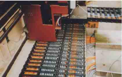

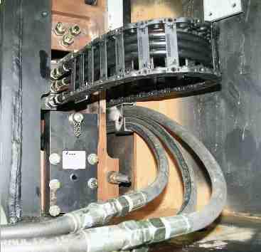
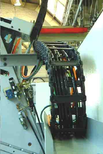
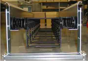
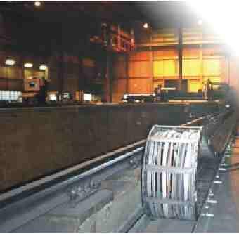
2 PKK APPLICATIONS robotics, handling equipment, machine tools, textile machinery 49

 part no.")


3 c a s a H r 50 g SD2 SD3 SD4 SD5 u Sn a p e m SD1 sta y length + k stay length + 2f stay length + g stay length t stay length + 2l h X1 h i h sta y len g th + g p w f v PKK DIMENIONS 0.5 x tra vel distance pretension F additional stay slider R app0.. 5 R B pitch lengt h L pretension: PKK 120 PKK 220 PKK 320 PKK 520 (see p.64) part no. H l radius PKK /- 4 mm/m 20 +/- 4 mm/m 17 +/- 4 mm/m 12 +/- 4 mm/m PKK PKK PKK PKK PKK PKK PKK PKK friction coefficient: 0.2 to 0.25 X1 SD1 SD2 SD3 SD4 SD5 PKK 210 2, , PKK 220 2, , PKK 310 3, ,5 PKK 320 3, ,5 flange connector v r s PKK 113, PKK short 19,5 14,5-213,223, PKK short 29, ,323, PKK short 29, , SD flange optional with Snap for toolless quick assembly k p w PKK PKK PKK PKK
4 PKK DIMENSIONS PKK pitch (stay 100) a c e 1) f g h i 2) m 3) t u kg/m 120, 121,123, 125, Ø , 111, 113, Ø , 221, 223, 225, Ø , 211, 213, Ø , 241, 243, Ø , 321, 323, 325, Ø , 311, 313, Ø , 341, 343, Ø , 521, 523, 525, Ø , 511, 513, Ø bending radius R [mm] 120, 121,123,1254), 1286) , 111, 113, 1154) , 221, 223, 2254), 2286) , 211, 213, 2154) , 241, 243, 2454) , 321, 323, 3254), 3286) , 311, 313, 3154) , 341, 343, 3454) , 521, 523, 5254), 5286) , 511, 513, 5154) stay length [mm] 1) 120,110,111,113,121,123, , ,210,211,213,221,223, , 2255) , 241, ) ,310,311,313,321,323, , 3255) , 341, ) ,510,511,513,521,523, , ) The usable interior width is stay length - 2e minus the width of the used PZ 2) First latching the PZ (latching all 2mm); PKK 215,225,245, 315, 325, 345 i=22; 3) Dimension does not apply to the closed type 4) PKK 115 and 125 from R50, 215 and 225 from R100, 245, 315 and 325 from R150, 345, 525 and 515 from R200 5) The inner radius covers (ASI) of length 200 mm of the PKK 215, 225, 245 and 300 mm and 200 mm of the PKK 315, 325, 345 are designed with a pivot on one side. 6) PKK 128 from R 50, PKK 228 from R100, PKK 328 from R150, PKK 528 from R200 weight 51
5 52 PKK TYPES PKK 120, 220, 320, 520 The standard version has a stay in every second link. With additional link bands and stays the chains can be extended as multibandchains. The integrated connector makes each link in the chain to a mounting link. order example PKK 220 / 100 x 3510 / 100 type radius length stay length PKK 110, 210,240, 310,340, 510 The smooth designed PKK corresponds to the standard version, but has no exterior T-slot. These types provide a very good visual effect and a smaller width through the flat outside surfaces (also see PKK 215, PKK 245). The PKK 240 and 340 offer larger cross sections due to the increased link height. order example PKK 240 / 100 x 3510 / 100 type radius length stay length PKK 121, 221, 321, 521 The types PKK -21 are manufactured with a stay in each link. The additional stays increase the lateral stability and optimize guiding of particularly smaller cable diameter. order example PKK 221 / 100 x 3510 / 100 type radius length stay length PKK 111, 211, 241, 311, 341, 511 These are the smooth designs with a stay in each link to increase lateral stability and optimize guiding of particularly small cables. PKK 241 and PKK 341 have a higher capacity due to their increased link height. order example PKK 241 / 100 x 3510 / 100 type radius length stay length


 and")
6 PKK TYPES PKK 113, 123, 213, 223, 243, 313, 323, 343, 513, 523 The PKK with extension stays in the inner radius. Suitable for low speeds these stays create additional space. The extension stays can be arranged in the outer radius or in other combinations as per optional drawing. The extension stays are available in two lengths. order example PKK 223 / 100 x 3510 / 100 type radius length stay length PKK 125, 225, 325, 525 The closed designs offer optimum protection of the lines against chips or against UV radiation. The covers can be opened in the inner or outer radius. The closed types may also be subsequently created from the standard version. PKK 115, 215, 245, 315, 345, 515 Without T-slot on the outside, the closed types achieve a good visual effect with their flat sides and a smaller width. order example PKK 215 / 100 x 3510 / 100 type radius length stay length PKK 128, 228, 328, 528 The PKK 128, 228 and 328 with sliders are designed for gliding arrangements (long travel distances) and are fitted with stays in each link. The sliders are mounted in the inner radius of the energy chain and have a very low coefficient of friction (µ = 0.2 to 0.25). The sliders can also be installed afterwards. At low stroke rates and low speeds (<1m / s) sliders are not necessary. The smallest radius of each dimension of the PKK is not suitable for sliders. order example PKK 228 / 100 x 3510 / 100 type radius length stay length Multiband energy chains Multiband energy chains can be created by attaching additional link bands. These are assembled through stays at standard energy chains (see assembly, except PKK with smooth exteriors). order example PKK 220 / 100 x 3510 / 100 / 100 type radius length stay length / stay length 53

7 54 PKK SIZES PKK120 height: 25 width: inner height: 16 inner width: PKK 220 height: 50 width: inner height: 34 inner width: PKK 240 height: 60 width: inner height: 44 inner width: PKK 320 height: 75 width: inner height: 51 inner width: PKK 340 height: 85 width: inner height: 60 inner width: PKK 520 height: 104 width: inner height: 80 inner width:
 4 SD / B (universal flange")
 11 22 ASA 100 (outer cover) 12 cover holder")

8 PKK PARTS pos. name 1 PKK 220 link 2 PKK 210 link 3 SD / Z (universal flange connector pivot) 4 SD / B (universal flange connector drilling) 5 PKK 220 connector link short (drilling) 6 PKK 220 connector link short (pivot) 7 head side flange SFA 8 spreader 9 22 stay ASI 100 (inner cover) ASA 100 (outer cover) 12 cover holder 13,13a PZ (plastic divider) 14 PT 55 / PT 75 (telescopic horizontal divider) 15 extension stay long 16 extension stay short 17 slider R damping element 19 band holder 20 ladder stay 23 horn stay PZ fork stay 25 PZ fork stay short 26 Snap (optional) a


 in the final position.")
9 click in stay unlock locking tabs push out stay fixed (2) (2) (2) (2) put on stay (3) movable PKK ASSEMBLY Packaging ekd energy chains are supplied in transport friendly packaging. When removing the packaging and during removal of the energy chain or parts of it, ensure that the energy chains are free of torsion and tension, to avoid mechanical damage. Lengthening or shortening, linkbands Lengthening of the energy chain is done by fitting of energy chain pieces or links and lock with spreader (2). To shorten the spreader is disengaged and removed, then the piece of chain removed. Alternatively first link strands may be mounted and then stays assembled. For the PKK the opposite link strands are rotated by 180 and arranged with the pivot on the inner chain. Stay assembly The stays with the locking tabs are put in the T-guide of the link and push until it clicks into the guides (2). The stays can be positioned initially in the T-guide and will be engaged in one swoop (plastic hammer or similar) in the final position. Stay disassembly The lock tongue of the stays are unlock with a screwdriver and the stays pushed out with light pressure to the front of the T-slot (2). For medium and larger series (from PKK220) the stays can be unlocked with a light hit on the lock tongue (plastic hammer or similar) and then ejected. Plastic divider PZ (vertical) The PZ will be placed in the designated position on the stay and engaged (2). The PZ can be mounted fixed or movable. The dismantling is done by unlocking (3) and removal of the PZ. 56
 and engaged in the designated height. The disassembly is done with a screwdriver through pull (2) and removal (3).")
.")
.")
. Covers and segment holder snap in the end position.")

10 PKK ASSEMBLY Telescopic divider and ladder divider The telescopic horizontal divider and ladder stay horizontally pushed onto the plastic divider (PZ) and engaged in the designated height. The disassembly is done with a screwdriver through pull (2) and removal (3). PZ fork stays The fork stays allow in combination with an additional stay a horizontal separation and several vertical separations. Fork stays are clipsed upon the stays like plastic divider PZ (p.56). Extension stays The extension stays are pushed onto the link guides and pivoted until it clicks. Then the stays are pushed into the guides ubtil it clicks (3). Covers Before installing covers (ASA/ASI) first segment holder have to be pushed in the T-slot of the links. Then the covers can be plugged in (2). Covers and segment holder snap in the end position. The covers are marked with arrows, to avoid wrong assembly direction. Covers for the outer radius are equipped with holders for divider (PZ). During assembly, ensure the correct overlap of the covers and that the covers are engaged on all four locking points. The inner radius covers (ASI) of length 200 mm of the PKK 215, 225, 245 and 300 mm of the PKK 315, 325, 345 are designed with a pivot on one side. The cover has to be pushed into the T-slot of the link on its pivot side and can swing to close or open (2). For that the cover holder has to be unlocked (see disassembly). (2) (3) (3) (2) (2) (2) 57


11 locking tab assembly inner radius outer radius disassembly PKK ASSEMBLY The dismantling of the covers is done by unlocking and lifting out. These are done one by one at a time with the 4 locking tongues on the segment holders using a screwdriver, then the cover is easy to raise. With two release tools all four locking tongues can be done at once and the cover removed. Attention: The release tools can only be resolved if covers are dismantled (by lateral withdrawal) Covers with lengths 200 mm and 300 mm of the PKK 225 and 325 are equipped with a pivot on one side. These covers opening mechanism is deactivated on one side. The covers can be swiveled. Sliders The sliders are mounted in the inner radius of the energy chain. The minimum bend radius in each PKK size can not be fitted with sliders. During assembly of the sliders be aware of the following: The sliders must be conditioned (water content min. 1%, overnight storage in water at room temperature or 2 h at 80 C). Heat the slider just before mounting in a water bath. Avoid impact load. The dismantling is carried out channel lock pliers as shown and unlock slider by turning it to the outer side. Multiband energy chains Multiband energy chains can be created by attaching additional link strands. These are attached to existing energy chains by additional stays (see stay assembly). By combining with extension stays large hoses or other additional components may be carried. 58


 and provide universal connection options, as an example with Snap for fast and toolless assembly.")


12 PKK ASSEMBLY Mounting the energy chain All ekd plastic energy chains are equipped with the integrated connector. When using integrated strain relief, no additional components are needed. Provision for the combined strain relief, the anchor profile has to be screwed with the first link in the chain. Separate strain relief can be subsequently mounted. Headside mounting Optionally, the attachment can be made with flange connectors or universal connectors. The flange connectors are mounted in the T-slots of short connectors links until locking. The energy chains can be attached through four flange connectors (2). The SD connectors are mounted like the links with the spreader (3) and provide universal connection options, as an example with Snap for fast and toolless assembly. Strain Reliefs With long travel distances and high speeds the lines at one end of the cable carrier, preferably on the moved driver, are attache to strain reliefs. The distance of strain relief to the bending area depends on the particulars of the line manufacturer. Integrated strain relief In this space-saving type strain reliefs are directly mounted on the vertical divider (PZ) of the first link of the energy chain. The mounting direction of the PZ must be chosen so that tension directed on the chain can not unlock the divider. In order to avoid premature line wear caused by dynamic loads a small extra chain length is recommended. Combined strain relief The combined strain relief combines the advantage of sufficient distance from the strain relief to the bending line areas provided by a simple and space-saving installation of the integrated strain relief. The anchor profile is fitted to the drilling dimensions of the energy chain (integrated connectors) and attached to this. The lateral insertion and extraction of strain relief elements is possible at any time. Separate strain relief The separate strain relief is recommended for high dynamic loads and large line diameters. A sufficient distance from the strain relief to the chain is easy to implement. integrated connector SD connectors (3) flange connectors (2) 59


 with the Blue Ribbon.")

13 ZLB24 part no ZLS10 part no ZLA8 part no ZHS10 part no ZLP xx part no (xx = chain width) stay l.+ 2 f ZL 100 part no.1612 ZL 80 part no.1675 ZL 50 part no s t a y l. + g Ø7< D <Ø35 h PKK ASSEMBLY ANCHOR PROFILE ZLP The aluminum anchor profile is used to mount various of strain relief elements. Both the distance to the energy chain as well as the positioning of the strain relief elements can be designed. STRAIN RELIEF STAY PZL The design of this strain relief stay is closely based on the plastic vertical divider (PZ). It is laterally inserted into the anchor profile or a c-profile and can accommodate multiple strain relief elements. BLUE RIBBON ZLB 24 The Blue Ribbon is a special ekd developed cable tie with a 24 mm wide fixing area for cable diameters of 7 mm to 35 mm. The Blue Ribbon can be locked on the strain relief stay. The lines may be fixed single or multiple (s-shaped) with the Blue Ribbon. PUSH ANCHOR ZLS 10 The push anchor is laterally inserted into the anchor profile or a c-profile. The lines are fixed with standard cable ties on the push anchor. CABLE ANCHOR ZLA 8 The cable anchor is pushed onto the strain relief stay and can be fixed by the latching at different altitudes. The line is connected with commercially available cable ties on the cable anchor (single or double). HORN STAY ZHS 10 The horn stay ZHS10 is transversely inserted into the anchor profile and locked by a 90 rotation. The line is fixed with cable ties at the horn. YOKE CLAMPS Commercially yoke clamps can be used as a separate strain relief (see below) and can be mounted with the aluminum c- profile of the SLE 520, SLE 320 in front of the energy chain connectors. 60
14 PKK ASSEMBLY Maintenance of the energy chain PKK energy chains are maintenance free. Like every mechanical system there will - depending on the ambient conditions - wear must be observed. In case of this the energy chain has to be replaced. For long travels or even in a circular motion, the energy chains are often equipped with sliding elements. These allow sliding of the upper part of the chain on a suitable surface (eg, slider-slider, slider-steel, glide bar). The sliders show wear according to the application due to abrasion. The slider surfaces should be checked at regular intervals on their condition. With a thickness of 1-2 mm sliders have to be replaced. 61
15 PKK parts Link m.v. with pretension 2 1 without pretension PKK PKK R R ,111 m.v , 121 m.v m.v m.v m.v m.v m.v R R , 211 m.v , 221 m.v m.v m.v m.v m.v m.v R , 241 m.v m.v m.v R R , 311 m.v , 321 m.v m.v m.v m.v m.v m.v R , 341 m.v m.v R R , 511 m.v , 521 m.v m.v. 523 m.v m.v. 525 m.v m.v PKK R PKK 210 / 0 5 Anschl PKK 210 / 0 2 Anschl special material parts like Ul94 V-0, EX or other have to be named in the order PKK PART NUMBERS
16 PKK PART NUMBERS PKK parts 55 9 P K K

17 PKK parts 55 special material parts like Ul94 V-0, EX or other have to be named in the order PKK ASA ASI ASA ASI ASA ASI ASA ASI ASA ASI SH SR ASK ASL GL PKK PART NUMBERS , , , Slider selection: See page
18 PKK PART NUMBERS PKK parts a PKK PZ GS GSK PTF PT55 PT75 LS HS FK SK SD B / Z SFA Snap 220/
PKK PKK CHARACTERISTICS. Dimensions. Travel. Travel speed. Acceleration. Temperature. Special versions APPLICATION AREAS. PLE max.
 PKK loa d / (kg/m) PKK 10 8 6 4 2 0 0 P KK 1 20 PKK applications 49 PKK dimensions 50 PKK types 52 PKK sizes 54 PKK parts 55 PKK assembly 56 PKK article numbers 62 LOAD DIAGRAM PKK 2 2 0 2 P KK 2 40 PKK
KEL 24 Cable entry frames
 24 Cable entry frames Split inserts Description Type Order No. Inserts KT PU small large The 24 matches exactly the cut-out dimensions of 24-pole standard industrial connectors. 24 42241 - The split insert
Processing Specification MiniBridge IDC
 Processing Specification MiniBridge IDC ERNI Electronics GmbH & Co. KG Seestrasse 9 l 73099 Adelberg / Germany l +49 7166 50-0 l www.erni.com Version 5 IMS Verarbeitungsspezifikationen Seite 1 von 11 Table
Up to 85% higher Service Life due to efficient sealing method.
 Robot Accessories Feeding through Up to 85% higher Service Life due to efficient sealing method. 346 Robot Accessories Feeding through Feeding through DDF 2 Rotary Feed-through Series Size Page DDF 2 348
3. Electronics and MMU2 unit assembly
 Written By: Jakub Dolezal 2018 manual.prusa3d.com/ Page 1 of 34 Step 1 Tools necessary for this chapter Please prepare tools for this chapter: 2.5mm Allen key for M3 screws 2mm Allen key for nut alignment
FOSC-600 C and D I N S T A L L A T I O N I N S T R U C T I O N
 FOSC-600 C and D I N S T A L L A T I O N I N S T R U C T I O N In-line and butt version Cold applied re-usable fiber optic closure Contents 1 Introduction 1.1 Product description 1.2 Capacity 2 General
3M Fiber Optic Splice Closure 2178-XSB/XSB-FR & 2178-XLB/XLB-FR 3M Cable Addition Kit 2181-XB/XB-FR
 3M Fiber Optic Splice Closure 2178-XSB/XSB-FR & 2178-XLB/XLB-FR 3M Cable Addition Kit 2181-XB/XB-FR Instructions July 2010 78-8135-0094-5-K 3 1.0 General 1.1 3M Fiber Optic Splice Closure 2178-XSB The
 www.mete-enerji.com.tr INDUSTIAL IEC PLUGS AND SOCKETS INDUSTIAL IEC PLUGS AND SOCKETS Position of the Earthing Contact acc. to IEC 60309-2 225/400-265/460 V~ 60 Hz (1) 3 P+N+ 3 P+ 2 P+ 120/208-144/250V~
KVT Split cable glands
 KVT Split cable glands Description Type Order Inserts KT Thread PU No. small large Thread length KVT is a circular split frame for quick and easy installation of cables or complete cable harnesses. Polyamide
3M Distribution Box (DDB)
") 3M Distribution Box (DDB) Merged Copper and Fiber Pole/Post Mount Enclosure Installation Instructions November 2015 78-0015-2736-1-A 2 November 2015 78-0015-2736-1-A Contents 1.0 General 2.0 Enclosure
3M Distribution Box (DDB) Merged Copper and Fiber Pole/Post Mount Enclosure Installation Instructions November 2015 78-0015-2736-1-A 2 November 2015 78-0015-2736-1-A Contents 1.0 General 2.0 Enclosure
with additional normally-open signalling contact l With integrated AS interface Safety at Work.
 Safety Hinge Switch SHS3 In addition to the plug connection version, an SHS with fixed cable connection at the rear is also available Right and left hinged systems possible for optimum cable routing Mounting
Nylon chains. AKAPP-STEMMANN Member of the Fandstan Electric Group. for cables and hoses AKAPP- STEMMANN BV. Fandstan Electric Group
 AKAPP- STEMMANN BV Fandstan Electric Group Nylon chains for cables and hoses NL 771 ME Barneveld Nijverheidsweg 1 Phone +1 (0) 0900 Fax +1 (0) 091 email info@akapp.com URL www.akapp.com This page shows
CABLE CARRIER MADE OF NYLON EASY CABLE INSTALLATION VERY LONG SERVICE LIFE FOR OFFICE FURNITURE AND INTERIORS
 CABLE CARRIER MADE OF NYLON EASY CABLE INSTALLATION VERY LONG SERVICE LIFE FOR OFFICE FURNITURE AND INTERIORS TSUBAKI KABELSCHLEPP PROTUM OFFICE P 0240 GS Outer height 23 mm Inner height 10 mm Outer width
Cable installation guidelines
 The Quality Connection Cable installation guidelines Business Unit Industrial Projects 2 Cable installation guidelines www.leoni-industrial-projects.com GENERAL Installation methods Many different methods
03-Durchfuehren_RZ_0708_EN.qxd:03-Durchfuehren GB.qxd :06 Uhr Seite 200 Feed-through
 Feed-through Feed-through FEED-THROUGH Series Size Page Rotary Feed-through for Robots DDF 202 DDF 031 206 DDF 040 208 DDF 040-1 210 DDF 050 212 DDF 050-1 214 DDF 063 216 DDF 080 218 DDF 080-1 220 DDF
Check what you have received against the component checklist and hardware above.
 SA46S SA46W SA46B SA46PB Component Checklist Installation Instructions SYSTEMA Systema Monitor Arm 460mm HARDWARE Display Mounting Spacers (x4) Display Mounting Screws Arm Assembly VESA monitor head M4
CONNECTING THE FUTURE 19" LINXS LIGHTWAVE INTEGRATED CROSS-CONNECT SYSTEM USER MANUAL
 CONNECTING THE FUTURE 19" LINXS LIGHTWVE INTEGRTED CROSS-CONNECT SYSTEM USER MNUL 109003 Issue Rev 2 19" Lightwave Integrated Cross-Connect System (LINXS) User Manual Document Number 109003 Issue Rev 2
2178-L/S Series Fiber Optic Splice Case with Gasket
 2178-L/S Series Fiber Optic Splice Case with Gasket Instructions for: 2178-S Splice Case 2178-LS Splice Case 2178-LL Splice Case 2181-LS Cable Addition Kit May 1997 34-7041-9949-5-A 1 Table of Contents
case 5 temperature sensor cosine sensor sine sensor ground + 5V phase 2- phase 2+ phase 1- phase 1+
 Motor Cables Accessories Motor Cables Extension cables tailo for use with Norgren NP Linear Motors are available in two different versions; standard and high flex for the use in trailing chains or cable
Installation Manual for New or Retrofit Installations
 Installation Manual for New or Retrofit Installations Release Date: 24-August-2015 c Able Applied Technologies LTD. READ THE ENTIRE MANUAL COMPLETELY AND CAREFULLY BEFORE STARTING BEFORE YOU BEGIN ASSEMBLY
FOSC 450 C6 and D6 Closures
 FOSC 450 C6 and D6 Closures I N S T A L L A T I O N I N S T R U C T I O N Fiber Optic Splice Closure 1. General Product Information The FOSC 450 C6 and D6 fiber optic splice closures use compressed gel
Swiveling unit. Smooth and precise swiveling
 NEW Swiveling unit RSP-FLEX Smooth and precise swiveling Swiveling unit RSP-FLEX Especially with automated loading and unloading of machine tools, the RSP-Flex swivel units offer an alternative to expensive
Photograph: GPA-JAKOB GmbH
 Photograph: GPA-JAKOB GmbH PRODUCT SELECTION made of plastic and steel Cable and hose carrier systems plastic, hybrid, and steel BASIC-LINE VARIO-LINE TUBE SERIES 3D-LINE STEEL-LINE Accessories Need help?
NEW SWIVELING UNIT RSP-FLEX. Smooth and precise swiveling
 NEW SWIVELING UNIT RSP-FLEX Smooth and precise swiveling SWIVELING UNIT RSP-FLEX Especially with automated loading and unloading of machine tools, the RSP-Flex swivel units offer an alternative to expensive
SPECIFICATION FIBER OPTIC SPLICE CLOSURE. Spec No : VSS-1007-BS403A-04A/SD. VSS-0107-BS403A-04A/SD R & D Center Manufacturing Division
 SPECIFICATION FIBER OPTIC SPLICE CLOSURE Model Spec. No. Distribution Depts. VSOF-BS403A VSS-0107-BS403A-04A/SD R & D Center Manufacturing Division Sales Division Management Division Revision 10. 07 (Rev.4)
Long Stroke and High-Speed Movement
 NS NS Rotating Nut inear Actuator ong and High-Speed Movement w w w. i n t e l l i g e n t a c t u a t o r. c o m Nut Rotation Actuator that Provides ong and Speed Nearly As Fast as a inear Speed 0 mm/s,
Medium Box for Cable Termination
 FIST-MB2-T I N S T A L L A T I O N I N S T R U C T I O N Medium Box for Cable Termination Contents 1 Introduction 1.1 Product description. 2 General 2.1 Tools 2.2 Kit contents 3 Installation and pre assembling
KVT Split cable glands
 KVT Description Type Order Grommets Thread PU KVT is a circular split frame for quick and easy installation and sealing of cables with connectors or complete cable harnesses. 3 KVT 20** 34 24 M20. Polyamide
Product group 1. Product description. At a glance. Cable entry systems for entering pre-terminated cables
 Product group 1 Cable entry systems for entering pre-terminated cables At a glance The patented cable entry system enables the user to enter, seal and provide strain relief for pre-terminated and standard
FIST-MB2-S. FIST Medium Box for Cable Splicing Only. 4 Cable installation. 1 Introduction. Contents. 2 General. 5. Fiber routing to individual trays
 FIST-MB2-S I N S T A L L A T I O N I N S T R U C T I O N FIST Medium Box for Cable Splicing Only Contents 1 Introduction 1.1 Product description 2 General 2.1 Tools 2.2 Kit contents 3 Installation and
Channel Cable Tray - Accessories
 Splice Plate The Splice Plate has the standard 4-hole pattern for all cable channel. Provided with straight sections and fittings. 9(*)-1043 3 (76) 9(*)-1044 4 (101) 9(*)-1044-6 6 (152) Horizontal Adjustable
APPLIANCES /// MTA, CST-100 II AND SL-156 CONNECTORS. CONNECTORS/ APPLIANCES MTA, CST-100 II and SL-156 Connectors
 PPLINCES /// MT, CST-100 II ND SL-156 CONNECTORS CONNECTORS/ PPLINCES MT, CST-100 II and SL-156 Connectors Contents Introduction This catalog has been designed to assist you, our customer, identify products
Fully ly Automaticti. Motorised Satellite t TV System. User s manual REV
 REV. 1.0 Fully ly Automaticti Motorised Satellite t TV System User s manual Customer Help Line: 1300 139 255 Support Email: support@satkingpromax.com.au Website: www.satkingpromax.com.au www.satkingpromax.com.au
CABLE MANAGEMENT PRODUCTS Cable Managers & Accessories
 CABLE MANAGEMENT PRODUCTS Cable Managers & Accessories Evolution Cable Management Page 5-3 Velocity Cable Management Page 5-8 Velocity Standard Pack Page 5-12 Vertical Cable Management Page 5-13 Global
Distributed Design Series
 D10SUB 10-INCH FEATURES Powerful, high-impact bass response Internal passive low-pass crossover Spring loaded Drop-Stop installation assistant tabs support the back can on the included rails and C-ring
Gigabit Multi-mode SX to Single Mode LX Converter. User s Manual NGF-728 Series. Warning COPYRIGHT
 COPYRIGHT Gigabit Multi-mode SX to Single Mode LX Converter User s Manual NGF-728 Series All rights reserved. No part of this publication may be reproduced, stored in a retrieval system, or transmitted
TECHNICAL SPECIFICATION
 TECHNICAL SPECIFICATION (FIBER OPTIC SPLICE CLOSURE) Model Spec. No. Distribution Depts. VSOF-BS403A SJP-0609-403A-01A/SD Quality Assurance Team Manufacturing Division Sales Division Management Division
CANNON STANDARD page 1 of 18. Cm5 MOTOR CONNECTOR
 CANNON STANDARD page 1 of 18 1 General Information... 2 1.1 Scope... 2 2 Ordering Code... 3 2.1 Housing / Motor Side... 3 2.2 Cable Side... 3 3 Explosion Drawing... 3.1 Explosion Complete Assembly... 3.2
Assembly Instructions
 Assembly Instructions REP Series Environmentally - Sealed Rectangular Plastic Connectors Hypertac S.A. January 2014 Assembly Instructions REP Series January 2014 1 Table of Contents I. Introduction A.
2179-CD Series Fiber Optic Splice Closure. Installation Instructions
 2179-CD Series Fiber Optic Splice Closure Installation Instructions 1.0 Product Introduction The new 3M TM 2179-CD Series Fiber Optic Splice Closure can be used in buried, underground, aerial, and pedestal
THE CABLE TRAY SYSTEM
 C A B L E S A N I T A T I O N C A B L E T R A Y S Y S T E M S THE CABLE TRAY SYSTEM The SILTEC cable tray system is a product, developed for optimum functionality and with focus on simplicity and accessibility,
Connectorized and Pre-Loaded HIGH PERFORMANCE CABLE CARRIER SYSTEMS
 Connectorized and Pre-Loaded HIGH PERFORMANCE CABLE CARRIER SYSTEMS TPC can provide complete packaged Cable Carrier solutions including the Connectors Within a cable carrier system, the cable package usually
SPECIFICATION. Spec No : VSS-1402-CS603B
 SPECIFICATION Spec No : VSS-1402-CS603B 1. INTRODUCTION 1.1. General This specification covers the design requirements and characteristics required of fiber optic splice closures to be used on fiber optic
0.3 mm Pitch, 1.5 mm Mated Height, Board- to-fine Coaxial Cable Connectors
 All non-rohs products have been discontinued, or will be discontinued soon. Please check the products status on the Hirose website RoHS search at www.hirose-connectors.com, or contact your Hirose sales
Orbit TM DIGITAL SHAKERS
 Orbit TM DIGITAL SHAKERS INSTRUCTION MANUAL Models P2, P4, M60, 300, 1000, 1900 Labnet International PO Box 841 Woodbridge, NJ 07095 Phone: 732 417-0700 Fax: 732 417-1750 email: labnet@labnetlink.com 2
Ribbon Cable connector Compliant with MIL Standard
 Ribbon Cable connector Compliant with MIL Standard HIF3B Series Features 1. Product Compliant with MIL Standard HIF3B series has been developed as a product compliant with MIL standard, and used for wide
Ribbon Cable connector Compliant with MIL Standard
 Ribbon Cable connector Compliant with MIL Standard HIF3B Series Product Specifications Rating Features 1. Product Compliant with MIL Standard HIF3B series has been developed as a product compliant with
3 SLiC Aerial Closure with Rubber End Seal
 3 Aerial Closure with Rubber End Seal Instructions 1.0 General 1.1 This instruction bulletin describes the assembly of the 3M Aerial Closure with external bonding hanger brackets. These closures are suitable
Panel-mounting thermostats, type series EM
 Data sheet 602025 Page /5 Panel-mounting thermostats, type series EM Particularities Operating temperature limiter Limit value range up to +650 C with temperature compensation Brief description Panel-mounting
Fiberglass - Technical Data
 - Technical Data Cable Tray Thermal Contraction and Expansion X : Denotes hold-down clamp (anchor) at support. _ : Denotes expansion guide clamp at support. It is important that thermal contraction and
Ribbon Cable connector Compliant with MIL Standard
 Ribbon Cable connector Compliant with MIL Standard HIF3B Series Features 1. Product Compliant with MIL Standard HIF3B series has been developed as a product compliant with MIL standard, and used for wide
PATCH PANEL Easy Patch INSTRUCTION MANUAL
 Page 1 BDA82-0 PATCH PANEL Easy Patch 96 Bantam (TT) Jacks 50 pin D-subminiature NPPA-TT-SD50 Easy Patch NPPA-TT-SD50 Page 2 BDA82-0 Index page 1 Electrical configuration 3 2 Re-Configuration and Replacement
NC-1000 INSTALLATION MANUAL NC-1000 FIBRE OPTIC CROSS-CONNECTION SYSTEM
 NC-1000 INSTALLATION MANUAL NC-1000 FIBRE OPTIC CROSS-CONNECTION SYSTEM Content 1. General 5 2. The products of NC-1000 system 6 3. Mounting of the frame 8 4. Earthing of the frame 8 NC-1000 FIBRE OPTIC
TECHNICAL INFORMATION
 OCTALUMINA 120: PARTS LIST AND TECHNICAL INFORMATION HIGH POWER LEDS INNER CORNER LABELED FRAME MOUNTED POWER SUPPLY UNIT EASY PLUG-IN CONNECTION BRACING TECHNIQUE CABLE OUTLET AT THE BOTTOM SYSTEM PACKAGING
Cables for robot applications
 Cables for robot applications 67 Primary cables Robot primary cable Cable design Internal conductor Special conductor Strand class VI (super-fine wire) Highly flexible Core insulation TPM or PUR Core identification
Necessary Data to Determine the Type of Cable Chain
 11015141100,S.11. RODAMIENTOS VIGO, S.A. Necessary Data to Determine the Type of Cable Chain The choice of cable chain should not only be based on a mathematical calculation of certain factors but should
All-Glass Sliding-System SF20
 Profile system All-glass sliding system Bottom loaded/running construction Option of flush or weathered bottom track The flush bottom track is particularly suitable for use in barrier-free dwellings according
SLiC Fiber Aerial Closure System
 3 SLiC Fiber Aerial Closure System SLFC 533-SP SLFC 533-TS SLFC 733-SP Instructions May 2005 78-8135-4502-3-B N C H E S R A N G E M IL L IM E T E R S.4 10.6.8 A B C 15 20 I 1.0 Kit Contents Note: Examine
High Density Block BRCP. HD BRCP- 128/192/256 pair. Installation Instructions
 High Density Block BRCP HD BRCP- 128/192/256 pair Installation Instructions Product Introduction The BRCP block is the latest generation of MDF terminal blocks developed by 3M, specifically designed for
Manual placement system MPL3100. for BGA, CSP and Fine-Pitch components
 Manual placement system MPL3100 for BGA, CSP and Fine-Pitch components Part No: MPL3100BA1.0e Issue Date: 02/2001 You have opted for an ESSEMTEC MPL3100 pick and place system. We thank you for this decision
Micro duct Cable with HDPE Sheath for Installation by Blowing
 Optical Fiber Cable Technology Specification INTERNAL Optical Fiber Cable Specification Micro duct Cable with HDPE Sheath for Installation by Blowing GCYFY-12/24/36/48/72/96/144/288/432/576B1.3 V7.0 2018-3-20,CCopyright.
3M Fiber Closures BPEO
 3M Fiber Closures BPEO 2 3M Fiber Closures BPEO The 3M Fiber Closures BPEO are designed with flexibility in application in mind. With a range of sizes, they can be deployed above grade (pole, facade) or
JUMO extherm-at Type , explosion-proof surface-mounted thermostat for zones 1, 2, 21, and 22
 Data Sheet 605055 Page 1/8 Type 605055, explosion-proof surface-mounted thermostat for zones 1, 2, 21, and 22 Special features Single thermostat with capillary or rigid thermowell and double thermostat
SECTION 4 TABLE OF CONTENTS
 Contents Introduction LC, SC and ST Series...4-2 Markets and Applications...4-2 International Standard Documents Compliance...4-2 LC Series Features and Benefits...4-3 LC Standard... 4-4 to 4-5 LC for
K Service Source. Apple High-Res Monochrome Monitor
 K Service Source Apple High-Res Monochrome Monitor K Service Source Specifications Apple High-Resolution Monochrome Monitor Specifications Characteristics - 1 Characteristics Picture Tube 12-in. diagonal
Bionic Elephant Trunk. Assembly Instructions
 Bionic Elephant Trunk Assembly Instructions Equipment and Supplies Required items from the Bionics Kit and/or Materials Pack: 1. Tail fin (small) assembled 2 see Start Here for tail fin assembly instructions
K Service Source. Apple High-Res Monochrome Monitor
 K Service Source Apple High-Res Monochrome Monitor K Service Source Specifications Apple High-Resolution Monochrome Monitor Specifications Characteristics - 1 Characteristics Picture Tube 12-in. diagonal
3M Fiber Optic Splice Closure 2178-XL & 2178-XL/FR
 3M Fiber Optic Splice Closure 2178-XL & 2178-XL/FR 3M Cable Addition Kit 2181-XL and 2181-XL/FR Instructions September 2017 78-8130-5055-2-M 2 September 2017 78-8130-5055-2-M 1.0 Kit Contents 2.0 General...
3M Fiber Optic Splice Closure 2178-XL & 2178-XL/FR 3M Cable Addition Kit 2181-XL and 2181-XL/FR
 3M Fiber Optic Splice Closure 2178-XL & 2178-XL/FR 3M Cable Addition Kit 2181-XL and 2181-XL/FR Instructions July 2010 3 1.0 Contents 1.0 General...3 2.0 Kit Contents...3 3.0 Cable Preparation...4 4.0
NEW. Datasheet. Field wiring Cabtite Easy Cable Entry System!
 Datasheet Field wiring Cabtite Easy Cable Entry System! NEW Do you really need a plug-in connector on the out-side of your switchgear cabinet? Or do you simply just want to make connections? Now you can
Installation instructions Roxtec RM ES B
 Installation instructions Roxtec RM ES B Environmental side Termination/ interior side Pipe Cable screen/armor Layers Termination/ interior side Cable sheath Layers Environmental side Vertical screen Plastic
Installation instructions Cable transit device Roxtec RS ES Ex
 General information Installation and maintenance: For European member countries of GENELEC, shall standard EN 60079-14 and EN 60079-17 be considered. For countries members of IECEx shall standard IEC 60079-14
DOME OPTIC SPLICE CLOSURE
 FIBER OPTIC SPIICE CLOSURE GJS-JKDH1001-120 BOX DIMENSION: W=140mm H=340mm Weight = 1.80 kgs Outer Internal structure Fuse fiber disc Type sealing ring Plastic hoop base Pole Mount Pole Mount 1 1. product
Panel-Mounted Thermostat
 Data Sheet 602026 Page 1/7 Panel-Mounted Thermostat EM Series Special features Safety temperature monitor STW (STB) Safety temperature limiter STB Tested according to DIN EN 14597 and PED 2014/68/EU Brief
Gel-sealed in-line fiber optic closure
 SCIL-C Gel donut INSTALLATION INSTRUCTION TC-1363-1-IP Rev A, Oct 2017 www.commscope.com Gel-sealed in-line fiber optic closure Contents 1 General 2 Sizing and product kit information 3 Installation conditions
HD Flex Patch Panel. ASSEMBLY VIEW (FLEX1UPN** shown) FS128B. CONTENTS: (#) indicates FLEX4UPN** quantity
 FS128B. CONTENTS: (#) indicates FLEX4UPN** quantity") HD Flex Patch Panel Part Numbers: FLEX1UPN**, FLEX2UPN**, FLEX4UPN** Panduit Corp. 2018 INSTALLATION INSTRUCTIONS Note: HD Flex Patch Panels are compatible with HD Flex Fiber System Components. HD Flex
HD Flex Patch Panel Part Numbers: FLEX1UPN**, FLEX2UPN**, FLEX4UPN** Panduit Corp. 2018 INSTALLATION INSTRUCTIONS Note: HD Flex Patch Panels are compatible with HD Flex Fiber System Components. HD Flex
STRAND LIGHTING 200F 7-INCH TUNGSTEN LED TELEVISION FRESNEL SPECIFICATION.
 STRAND LIGHTING 200F 7-INCH TUNGSTEN LED TELEVISION FRESNEL SPECIFICATION. GENERAL. A.) Overview. 1) The Television Fresnel fixture shall be purpose designed for television and studio lighting applications.
ASSEMBLY, INSTALLATION, AND REMOVAL OF CONTACTS AND MODULES
 ASSEMBLY, INSTALLATION, AND REMOVAL OF CONTACTS AND MODULES FOR 75 OHM AND 75 OHM HD COAXIAL CONTACTS AND MODULES Table of Contents SECTION 1 RECEIVER CONTACT ASSEMBLY INSTRUCTIONS SECTION 2 ITA CONTACT
Installation instructions Roxtec RS ES Ex
 General information Installation and maintenance: For European member countries of GENELEC, shall standard EN 60079-14 and EN 60079-17 be considered. For countries members of IECEx shall standard IEC 60079-14
INSTALLATION INSTRUCTIONS MO023A
 INSTALLATION INSTRUCTIONS MO023A Nexans N3S ODF system NEXANS N3S ODF SYSTEM Content Product description Patching frame Splice frame Doors Splice module Patch module Protective cover and label panel Guides
3.22 Finalize exact specifications of 3D printed parts.
 3.22 Finalize exact specifications of 3D printed parts. This is the part that connect between the main tube and the phone holder, it needs to be able to - Fit into the main tube perfectly - This part need
All-Glass Sliding-System SF20
 Profile system All-glass sliding system Bottom loaded/running construction Option of flush or weathered bottom track The flush bottom track is particularly suitable for use in barrier-free dwellings according
Aerial Cable Installation Best Practices
 Aerial Cable Installation Best Practices Panduit Corp. 2007 BEST PRACTICES Table of Contents 1.0 General... 3 2.0 Introduction... 3 3.0 Precautions... 4 4.0 Pre-survey... 5 5.0 Materials and Equipment...
VIP-2/SC/FLK20. Extract from the online catalog. Order No.:
 Extract from the online catalog VIP-2/SC/FLK20 Order No.: 2315049 The illustration shows a 16-position version VARIOFACE module, with screw connection and flat-ribbon cable plug connector, for mounting
PJ PRODUCTION PRODUCT CATALOGUE DESIGN, DEVELOPMENT AND PRODUCTION OF OFFICE ACCESSORIES FOR MODERN WORKPLACES
 PJ PRODUCTION PRODUCT CATALOGUE DESIGN, DEVELOPMENT AND PRODUCTION OF OFFICE ACCESSORIES FOR MODERN WORKPLACES DESIGN, FUNCTIONALITY & ERGONOMICS With products from PJ Production, your customer can enjoy
RAIL BULL TRACK WELDING CARRIAGE WITH OSCILLATOR
 RAIL BULL TRACK WELDING CARRIAGE WITH OSCILLATOR The Rail Bull is a track welding carriage designed to produce butt and fillet welds with or without oscillation. The carriage can work in PA (flat), PB
Profile 10F User Manual
 Version 4.0 Profile 10F User Manual For Products: Vivid Wave Mini PLEASE READ THESE INSTRUCTIONS CAREFULLY BEFORE INSTALLATION. INCORRECT INSTALLATION AND HANDLING CAN VOID YOUR WARRANTY. Table of Contents
DIGITAL DISTRIBUTING FRAME (DDF) INSTALLATION PROCEDURES FOR PANELS AND MODULES
 INSTALLATION PROCEDURES FOR PANELS AND MODULES") DIGITAL DISTRIBUTING FRAME (DDF) INSTALLATION PROCEDURES FOR PANELS AND MODULES CommScope 365-301-136-1 Instruction Sheet Issue 10, February 2004 Material ID 847 591 963 General The Digital Distributing
DIGITAL DISTRIBUTING FRAME (DDF) INSTALLATION PROCEDURES FOR PANELS AND MODULES CommScope 365-301-136-1 Instruction Sheet Issue 10, February 2004 Material ID 847 591 963 General The Digital Distributing
TEK-LCD 7801A. NEMA 4X Loop-Powered Feet and Inches Level Meter. ACCESSORIES. Technology Solutions
 Technology Solutions TEK-LCD 7801A NEMA 4X Loop-Powered Feet and Inches Level Meter ACCESSORIES www.tek-trol.com Flow Level Temperature Pressure Valves Analyzers Accessories TekValSys Introduction The
SHARP Plasma inverter cutting range
 SHARP Plasma inverter cutting range Sword edge cutting www.cemont.com The plasma expert advanced powerful all metals performance portable solutions plasma gouging maintenance high quality The plasma process
0.4 mm Pitch, Horizontal mating, Board- to-fine Coaxial Cable Connectors
 0.4 mm Pitch, Horizontal mating, Board- to-fine Coaxial Cable Connectors DF49 Series Reliable connection 0.7±0.1 (Mated height) (0.5) Effective mating length Figure. 1 Mis-insertion Prevention Features
LED-Strip C12 MK2.6. Product Sheet
 LED-Strip C12 MK2.6 Product Sheet schnick-schnack-systems Introduction features Generation 3 compatible Automatic Addressing System (Smart-Link) no addressing at the board Compatible with other series
Laying of cables and lines in electrical installations and data networks
 Technical bulletin Laying of cables and lines in electrical installations and data networks Date: 08/2006 This technical bulletin provides you with information on specific technical subjects. It is based
VIP-3/SC/FLK40. Extract from the online catalog. Order No.:
 Extract from the online catalog VIP-3/SC/FLK40 Order No.: 2315078 VARIOFACE module, with screw connection and flat-ribbon cable plug connector, for mounting on NS 32 or NS 35/7.5, with pin strip and short
Installation instructions Roxtec RM ES
 Installation instructions Roxtec RM ES Environmental side Environmental side Pipe Cable screen/armor Layers Layers Cable sheath Vertical screen Plastic film Conductive tape Integrated environmental sealing
CITOCUT Plasma inverter cutting range
 CITOCUT Plasma inverter cutting range Sword edge cutting www.oerlikon-welding.com The plasma expert advanced plasma cutting powerful all metals performance portable solutions inverter plasma gouging maintenance
Cable and Power Management Open-Frame Rack Cable Managers
 Spec-001 Cable and Power Management Open-Frame Rack Cable Managers CABLETEK Horizontal Cable Manager DCHD shown DCHS4 shown Arrowhead fingers funnel cable into base and hold it securely Vertical and horizontal
LED-Strip C25 MK2.6. Product Sheet
 LED-Strip C25 MK2.6 Product Sheet schnick-schnack-systems Introduction features Generation 3 compatible Automatic Addressing System (Smart Link) no addressing at the board Compatible with other series
Interface Connectors for Miniature, Portable Terminal Devices
 NEW Interface Connectors for Miniature, Portable Terminal Devices ST Series Strong locking mechanism Right Mating direction Left Top 9N max. Overview Developed as external input/output connectors for the
MANUAL CABLE MARKING SYSTEM PMP-30 PUSH-IN CABLE MARKERS WITH HOLDERS
 MANUAL CABLE MARKING SYSTEM Provides alternative manual systems for identifying cables, tubes, conduit, components and equipment. PMP push-in cable markers for use with PM transparent holders RMS and FMS