TruePlate Structural Plate
|
|
|
- Baldwin Jennings
- 6 years ago
- Views:
Transcription

1 TruePlate Structural Plate Galvanized Steel and Aluminum Alloy Sizes, Shapes and Height of Cover Tables TrueNorthSteel.com


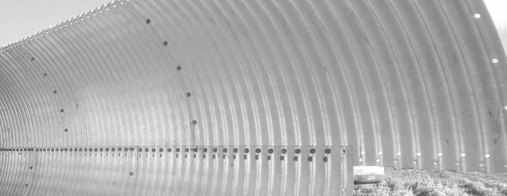
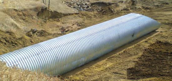
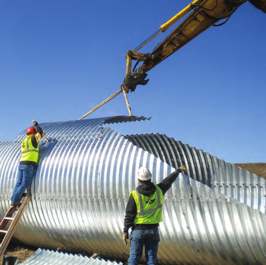
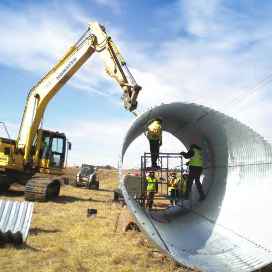
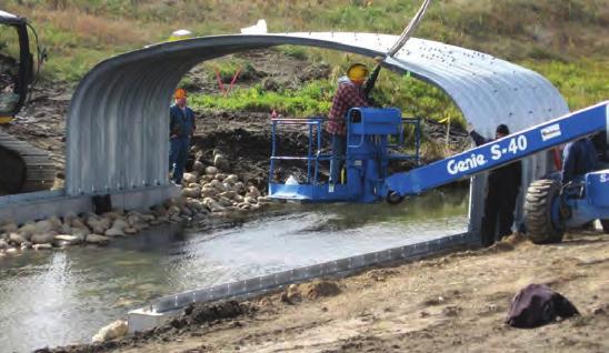
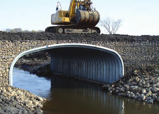
2 TruePlate Structural Plate Many drainage and bridge applications exceed the size and design limitations of standard corrugated metal pipe. In these cases, structural plate can provide a solution by offering larger sizes, heavier gages and specialized shapes to meet almost any application requirement. TrueNorth Steel offers expert design support to engineers, owners and contractors and provides customized solutions for your drainage culvert or bridge application including: Large drainage or underpass structures up to 50 diameter Bottomless arches up to 83 span Box Culverts low rise/wide span up to 35 clear span Bottomless structures for stream or wetlands crossings High fill heights and high live load applications Advantages Of TruePlate Structural Plate Include: Design versatility Low installed cost relative to cast-in-place or precast concrete and small bridges Easily installed in difficult or remote site situations Designed to meet your life-cycle requirements Less maintenance No bridge expansion joints for a smooth driving surface
3


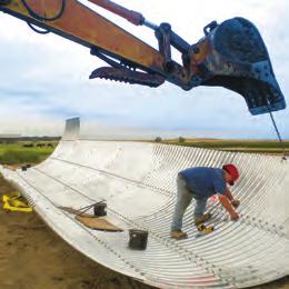
4 Engineering Support The TrueNorth Steel engineering team can support engineers, owners, and contractors using TruePlate galvanized steel or aluminum alloy. You can rely on our experience and resources in all aspects of the design of structural plate including: material selection; structural and hydraulic design; footing designs; detailing and installation. Additionally, we can provide fully engineered solutions stamped by professional engineers. Contact us for: Specifications Drawings End treatment details Assembly assistance Installation guidance The following are typical steps in the design of structural plate culverts, storm drains, underpasses, and bridges: Clearance analysis for pedestrian and vehicular passage Hydraulic sizing Structural design and resulting material properties Foundation design Environmental design and resulting material or coating selection Structure end treatment design Specifications: Material and Installation
5 TruePlate Steel and Aluminum Structural Plate Shape Steel 6 x 2 Corrugation Aluminum x 2.5 Corrugation Steel x 5.5 Corrugation Applications ROUND Diameter Diameter Diameter 5 to 26 6 to to 51 3 Culvert, railroad, vehicular or pedestrian underpass, caisson, vertical shaft, culverts, subdrains, sewers, service tunnels, etc. All plate same radius, for medium and high fills (or trenches). PIPE ARCH Span x Rise Span x Rise 6 1 x 4 7 to 20 7 x x 5 8 to x 11 ARCH Single Radius Span x Rise Span x Rise Span x Rise 6 x 1 to 26 x 11 6 x 1 to 23 x x 11 5 to 82 x 42 Low rise culvert provides greater flow area at low elevations where headroom is limited. Has hydraulic advantages at low flows. Corner plate radius 31. Low rise culvert, bottomless arch, fish passage, vehicular or pedestrian underpass, corrugated footings, cast-in-place or precast concrete footings. ARCH Multiple Radius Span x Rise Span x Rise 5 x 8 4 to 50 7 x 1 11 BOX CULVERT Span x Rise Span x Rise 8 x 2 7 to 25 5 x 2 8 x 2 6 to 35 3 x 7 UNDERPASS Span x Rise Span x Rise 5 8 x 5 to 20 4 x x 5 to 20 5 x 17 ELLIPSE - Horizontal Span x Rise Span x Rise 7 4 x 5 6 to 11 x x 6 8 to 11 x 11 2 ELLIPSE - Vertical Span x Rise Span x Rise 4 8 x 5 2 to 25 0 x x 6 3 to 20 x x 3 to 51 8 x 11 Aesthetically pleasing low clearance and large waterway openings. Low rise long span structures. Culverts, bridges and underpasses. Constructed on cast-in-place concrete footings or slabs. Low rise culvert, short span bridge, corrugated footings, cast-in-place or pre-cast concrete footings, full corrugated invert. Low-wide waterway enclosures, culverts, storms sewers. Vehicular or pedestrian underpass. For pedestrians, livestock or vehicles. Low rise culvert, vehicular or pedestrian underpass, grade separations. Vehicular or Pedestrian Underpass, Culverts, sewers, service tunnels, recovery tunnels. Plates of varying radii: shop fabrication. For appearance and where backfill compaction is only moderate. Structural Plate Meets The Following Specifications MATERIALS ASTM A761 Corrugated Steel Structural Plate, Zinc Coated for Field Bolted Pipe, Pipe Arches and Arches ASTM 64 Corrugated Steel Box Cuvlerts ASTM B746 Corrugated Aluminum Alloy Structural Plate for Field Bolted Pipe, Pipe Arches and Arches ASTM B864 Corrugated Aluminum Alloy Box Culverts AASHTO M167 Corrugated Steel Structural Plate, Zinc Coated for Field Bolted Pipe, Pipe Arches and Arches AASHTO M21 Corrugated Aluminum Alloy Structural Plate for Field Bolted Pipe, Pipe Arches and Arches INSTALLATION ASTM A807 Practice for Installing Corrugated Steel Structural Plate Pipe for Sewers ASTM B78 Practice for Installing Corrugated Aluminum Structural Plate Pipe for Culverts and Sewers AASHTO LRFD Bridge Construction Specifications, Section 26, Metal Culverts DESIGN ASTM A76 Practice for Structural Design of Corrugated Steel Pipe, Pipe Arches and Arches ASTM B70 Practice for Structural Design of Corrugated Aluminum Pipe, Pipe Arches and Arches AASHTO LRFD Bridge Design Specifications, Section, Buried Structures and Tunnels AREMA Manual for Railway Engineering, Section 4 Culverts


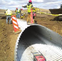
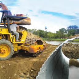
6 6 Sizes, Shapes and Height of Cover Tables The design tables for Steel Structural Plate Pipe and Pipe Arch contained in this document are excerpted from the National Corrugated Steel Pipe Association s Corrugated Steel Pipe Design Manual. The design tables for Aluminum Structural Plate are excerpted from the original Aluminum Association Aluminum Products Drainage Manual which is no longer in publication. For more complete design information or design support for Structural Plate, please contact your TrueNorth Steel representative. The tables contained in this document are meant as a general reference and TrueNorth Steel always recommends that each application should be analyzed specifically. Minimum allowable cover amounts are a function of the listed live loads whether HS-20, HS-25 or HL-3. Construction loads applied may be greater than HS-20, HS- 25, HL-3 and E-80 and may require greater temporary cover. All structural plate designs should include a thorough foundation analysis. Arch Structural Plate and Aluminum Box Culverts require additional foundation design attention because they are often constructed on either corrugated metal footing pads, upon concrete footings or slabs. TrueNorth Steel is available to assist with the design of any of these options. The successful installation of any corrugated structure is highly dependent upon the backfill material and backfilling process. The National Corrugated Steel Pipe Association publishes specific backfill selection and backfill process guidance within the Corrugated Steel Pipe Design Manual. ASTM A807 also provides comprehensive installation guidance for steel structural plate and ASTM B78 provides the same guidance for aluminum structural plate. Finally, an appropriate end treatment such as beveled ends, concrete slope collars, headwalls or scour cut-off toe walls will ensure long term stability of the structure. TrueNorth Steel has extensive experience with this feature and all of the design requirements of structural plate.
7 7 Structural Plate Height of Cover Table of Contents Steel 6 x 2 Corrugation Round Structural Plate Steel...8- Pipe Arch Structural Plate Steel...- Elliptical Structural Plate Steel...- Underpass Structural Plate Steel Single Radius Arch Structural Plate Steel Steel - Deep Corrugation Round Structural Plate Deep Corrugation Steel Single Radius Arch Deep Corrugation Steel...22 Arch Structural Plate Deep Corrugation Steel Aluminum Structural Plate Round, Vertical Ellipse Structural Plate Aluminum Single Radius Arch Structural Plate Aluminum Pipe Arch Structural Plate Aluminum Underpass Structural Plate Aluminum... 2 Box Culvert Structural Plate Aluminum Structure Selection Examples... TrueNorthSteel.com info@truenorthsteel.com
8 8 Round Structural Plate Steel 6 x 2 Corrugation AISI-7 Height of Cover Limits for Steel Pipe H25 Live Load 6 x 2 Corrugation Diameter M* or Span, Maximum Cover (ft) for Specified Thickness () Cover, ft Excerpted from National Corrugated Steel Pipe Association AISI American Iron and Steel Institute
9 Round Structural Plate Steel 6 x 2 Corrugation AISI-8 Height of Cover Limits for Steel Pipe E80 Live Load 6 x 2 Corrugation Diameter M* or Span, Maximum Cover (ft) for Specified Thickness () Cover, ft ** ** ** ** ** ** ** ** ** ** Notes: * From top of pipe to bottom of tie. ** These pipe require additional minimum cover. Excerpted from National Corrugated Steel Pipe Association AISI American Iron and Steel Institute
10 Pipe Arch Structural Plate Steel 6 x 2 Corrugation AISI- Height-of-Cover Limits for Structural Plate Pipe Arch R C Corner Radius H20 or H25 Live Load 6 x 2 Corrugation Size Span ft Rise ft Minimum Specified Thickness Required Minimum* Cover Maximum Cover (ft) Over Pipe Arch for the Following Soil Corner Bearing Capacities 2 tons/ft 2 3 tons/ft 2 Notes: 1. Soil bearing capacity refers to the soil in the region of the pipe corners. See Chapter for design of pipe envelope at pipe corners. The remaining backfill around the pipe arch must be compacted to a specified AASHTO T- density of 0%. 2. Use reasonable care in handling and installation. 3. Pipe arches are typically used where the cover does not exceed feet. * Minimum covers are for H20 and H25 loads. See Table 7.8 for construction load requirements. Minimum covers are measured from top of pipe to bottom of flexible pave-ment or top of pipe to top of rigid pavement. Minimum cover must be maintained in unpaved traffic areas. Excerpted from National Corrugated Steel Pipe Association AISI American Iron and Steel Institute
11 Pipe Arch Structural Plate Steel 6 x 2 Corrugation 11 AISI- Height-of-Cover Limits for Structural Plate Pipe Arch 31 R C Corner Radius H20 or H25 Live Load 6 x 2 Corrugation Size Span ft Rise ft Minimum Specified Thickness Required Minimum* Cover Maximum Cover (ft) Over Pipe Arch for the Following Soil Corner Bearing Capacities 2 tons/ft 2 3 tons/ft 2 Notes: 1. Soil bearing capacity refers to the soil in the region of the pipe corners. See Chapter for design of pipe envelope at pipe corners. The remaining backfill around the pipe arch must be compacted to a specified AASHTO T- density of 0%. 2. Use reasonable care in handling and installation. * Minimum covers are for H20 and H25 loads. See Table 7.8 for construction load requirements. Minimum covers are measured from top of pipe to bottom of flexible pave-ment or top of pipe to top of rigid pavement. Minimum cover must be maintained in unpaved traffic areas. Excerpted from National Corrugated Steel Pipe Association AISI American Iron and Steel Institute
12 Pipe Arch Structural Plate Steel 6 x 2 Corrugation AISI-16 Height-of-Cover Limits for Structural Plate Pipe Arch R C Corner Radius E80 Live Load 6 x 2 Corrugation Span ft Size Rise ft Minimum Specified Thickness Required Minimum* Cover Maximum Cover (ft) Over Pipe Arch for the Following Soil Corner Bearing Capacities 2 tons/ft 2 3 tons/ft 2 4 tons/ft 2 Notes: 1. Soil bearing capacity refers to the soil in the region of the pipe corners. See Chapter for design of pipe envelope at pipe corners. The remaining backfill around the pipe arch must be compacted to a specified AASH- TO T- density of 0%. 2. Use reasonable care in handling and installation. 3. Pipe arches are typically used where the cover does not exceed feet. * From top of pipe to bottom of tie. Excerpted from National Corrugated Steel Pipe Association AISI American Iron and Steel Institute
13 Pipe Arch Structural Plate Steel 6 x 2 Corrugation AISI-17 Height-of-Cover Limits for Structural Plate Pipe Arch 31 R C Corner Radius E80 Live Load 6 x 2 Corrugation Size Span ft- Rise ft- Minimum Specified Thickness Required Minimum* Cover Maximum Cover (ft) Over Pipe Arch for the Following Soil Corner Bearing Capacities 2 tons/ft 2 3 tons/ft Notes: 1. Soil bearing capacity refers to the soil in the region of the pipe corners. See Chapter for design of pipe envelope at pipe corners. The remaining backfill around the pipe arch must be compacted to a specified AASHTO T- density of 0%. 2. Use reasonable care in handling and installation. 3. Pipe arches are typically used where the cover does not exceed feet. *From top of pipe to bottom of tie. Excerpted from National Corrugated Steel Pipe Association AISI American Iron and Steel Institute
14 Elliptical Structural Plate Steel 6 x 2 Corrugation AISI- Height-of-Cover Limits for Structural Plate Horizontal Elliptical Pipe H20 or H25 Live Load 6 x 2 Corrugation Pipe Size E 27 E E E 33 E 33 E E E E 21 3 E 3 E 3 E 21 3 E 42 E 42 E 42 E E 45 E 45 E 45 E E E E 21 E E 27 E Span ft Rise ft R T R s Minimum* Cover Minimum Specified Thickness Required Maximum Cover (ft) Over Pipe for Side and Haunch Soil Bearing Capacity of 2 tons/ft 2 Notes: 1. Soil bearing capacity refers to the soil in the region of the pipe haunches. See Chapter for design of pipe envelope at pipe haunches. The remaining backfill around the ellipse must be compacted to a specified AASH- TO T- density of 0%. 2. Use reasonable care in handling and installation. * Minimum covers are for H20 and H25 loads. See Table.1 for construction load requirements. Minimum covers are measured from top of pipe to bottom of flexible pavement or top of pipe to top of rigid pavement. Minimum cover must be maintained in unpaved traffic areas Excerpted from National Corrugated Steel Pipe Association AISI American Iron and Steel Institute
15 Elliptical Structural Plate Steel 6 x 2 Corrugation AISI-1 Height-of-Cover Limits for Structural Plate Horizontal Elliptical Pipe E80 Live Load 6 x 2 Corrugation Pipe Size E 27 E E E 33 E 33 E E E E 21 3 E 3 E 21 3 E 42 E 42 E E 45 E 45 E E E E 21 E E 27 E Span ft Rise ft R T R s Minimum* Cover 42 Minimum Specified Thickness Required Maximum Cover (ft) Over Pipe for Side and Haunch Soil Bearing Capacity of 3 tons/ft 2 Notes: 1. Soil bearing capacity refers to the soil in the region of the pipe haunches. See Chapter for design of pipe envelope at pipe haunches. The remaining backtill around the ellipse must be compacted to a specified AASH- TO T- density of 0%. 2. Use reasonable care in handlgng and installation. * From top of pipe to bottom of tie. Excerpted from National Corrugated Steel Pipe Association AISI American Iron and Steel Institute
16 16 Underpass Structural Plate Steel 6 x 2 Corrugation AISI-20 Height-of-Cover Limits for Structural Plate Underpass H20 or H25 Live Load 6 x 2 Corrugation Size Span ft Rise ft R c Corner Radius Minimum Specified Thickness Required 0.8 Minimum* Cover Maximum Cover (ft) Over Underpass for Soil Corner Bearing Capacity of 2 tons/ft l Notes: 1. Soil bearing capacity refers to the soil in the region of the pipe corners. See Chapter for design of pipe envelope at pipe corners. The remaining backfill around the underpass must be compacted to a specified AASHTO T- density of 0%. 2. Use reasonable care in handling and installation. * Minimum covers are for H20 and H25 loads. See Table.1 for heavy construction load requirements. Minimum covers are measured from top of pipe to bottom of flexible pavement or top of pipe to top of rigid pavement. Minimum cover must be maintained in unpaved traffic areas. Excerpted from National Corrugated Steel Pipe Association AISI American Iron and Steel Institute
17 Underpass Structural Plate Steel 6 x 2 Corrugation 17 AISI-21 Height-of-Cover Limits for Structural Plate Underpass E80 Live Load 6 x 2 Corrugation Size Span ft Rise ft R c Corner Radius Minimum Specified Thickness Required 0.8 Minimum* Cover Maximum Cover (ft) Over Underpass for Soil Corner Bearing Capacity of 2 tons/ft Notes: 1. Soil bearing capacity refers to the soil in the region of the pipe corners. See Chapter for design of pipe envelope at pipe corners. The remaining backfill around the underpass must be compacted to a specified AASHTO T- density of 0%. 2. Use reasonable care in handling and installation. * From top of pipe to bottom of tie. Excerpted from National Corrugated Steel Pipe Association AISI American Iron and Steel Institute
18 Single Radius Arch Structural Plate Steel 6 x 2 Corrugation AISI-22 Height-of-Cover Limits for Structural Plate Arches Rise H20 or H25 Live Load 6 x 2 Corrugation Span 0. M* Span, Maximum Cover (ft) for Specified Thickness () Cover, ft Notes: 1. Arches with R/S less than 0. require special design. * Minimum covers are for H20 and H25 loads. See Table.1 for heavy construction load requirements. Minimum covers are measured from top of pipe to bottom of flexible pavement or top of pipe to top of rigid pavement. Minimum cover must be maintained in unpaved traffic areas. Excerpted from National Corrugated Steel Pipe Association AISI American Iron and Steel Institute
19 Single Radius Arch Structural Plate Steel 6 x 2 Corrugation 1 AISI-23 Height-of-Cover Limits for Structural Plate Arches Rise E80 Live Load 6 x 2 Corrugation Span 0. M* Span, Maximum Cover (ft) for Specified Thickness () Cover, ft ** ** ** ** ** ** ** ** Notes: 1. Arches with R/S less than 0. require special design. * From top of pipe to bottom of tie. ** These structural plate arches require additional minimum cover. Excerpted from National Corrugated Steel Pipe Association AISI American Iron and Steel Institute


20 20 Deep Corrugated Structural Plate Deep corrugated Steel Structural Plate presents owners, engineers and contractors with a material exhibiting deep corrugations resulting in a very strong and stiff section. This section lends itself well to large diameter and longer span structures. The following pages describe common structure sizes and shapes that may be constructed using deep corrugated Steel Structural Plate. Due to the complexity and critical nature of these large structures, TrueNorth Steel recommends a case-by-case analysis of each structure under consideration. Contact your TrueNorth Steel representative for assistance.
21 Round Structural Plate Deep Corrugation Steel x 5-1/2 Corrugation 21 Table 2.3 Structural plate long span round (1) x 5 1/2 corrugation bolted seams Inside Diameter Periphery End Area ft - S* ft Note: 1. All dimensions are to the inside crest and subject to manufacturing tolerances. 2. Other sizes are available. 3. All structures should be reviewed based on live load and geotechnical conditions *S = 16 Excerpted from National Corrugated Steel Pipe Association
22 22 Single Radius Arch Deep Corrugation Steel x 5-1/2 Corrugation Table 2.40 Deep Corrugated Arches Sizes and layout details (1) x 5-1/2 in corrugation profile bolted seams able 2. Span Total Rise End Area Inside Radius (ft-) (ft-) (ft 2 ) (ft-) Total S* 22' 11" 11' 5" ' 5" 27 23' " 11' 11" ' 11" 28 ' 8" ' 4" 2 ' 4" 2 25' 1" ' 6" 255 ' " 26' 4" ' 2" 272 ' 2" 31 27' 2" ' 7" 21 ' 7" 32 28' 1" ' 0" ' 0" 33 28' " ' 5" 327 ' 5" 34 2' " ' " 347 ' " 35 ' 7" ' 3" 7 ' 3" 31' 5" ' " 7 ' " 37 32' 3" 16' 2" 40 16' 2" 33' 2" 16' 6" " 7" 3 34' 0" 17' 0" ' 0" 40 35' 8" 17' " 4 17' " 42 37' 4" ' 8" 5 ' 6" 44 3' 1" 1' 6" 600 1' 6" 46 40' " 20' 4" ' 4" 42' 6" 21' 3" ' 3" 50 44' 2" 22' 1" ' 1" 52 45' " 22' 11" ' 11" 54 4' 3" ' 11" 53 ' 7" 58 50' 11" 25' 6" 1 25' 6" 60 52' 8" 26' 4" 88 26' 4" 62 54' 8" 27' 2" 1 27' 2" 64 56' 6" 28' 4" 34 28' 3" 66 57' 8" 28' " 1 28' " 68 5' 5" 2' " 87 2' " 70 62' " 31' 5" ' 5" 74 66' 3" 33' 1" ' 2" 78 67' 11" 34' 0" 34' 0" 80 6' 7" 34' " 3 34' " 82 73' 0" ' 6" 204 ' 6" 86 74' 8" 37' 4" ' 4" 88 78' " 3' 6" 3' 4" 3 82' 0" 41' 0" ' 0" 6 Note: 1. All dimensions Structural are to the inside plate crest long and subject span single to manufacturing radius tolerances. arch - size 2. Other sizes are available. x 51#2 corrugation - bolted seams 3. All structures should be reviewed based on live load and geotechnical conditions. *S = 16 Excerpted from National Corrugated Steel Pipe Association
23 Arch Structural Plate Deep Corrugation Steel x 5-1/2 Corrugation 23 Table 2.41 Structural plate multi-radius arches size and layout details x 5-1/2 corrugations bolted seams Max Span Bottom Span Total Rise End Area Inside Radius Inside Radius Return (ft-) (ft-) (ft-) (ft 2 ) Side Crown Angle Total S* () () degrees 26' 3" 26' 3" 11' " ' 6" 2' 6" ' 4" ' 3" 28' 7" 16' 11" ' 2" 31' 0" ' 0" ' " 32' 8" ' 0" ' " 31' 11" ' 11" ' " 31' " 17' 7" ' 5" 34' 4" ' " ' 1" 35' 11" ' " ' 1" 35' 1" ' 8" ' 1" 35' 3" 1' 3" ' " 37' 7" ' " ' 4" 3' 3" ' 0" ' 4" ' 8" ' 6" ' 4" ' 0" 20' 0" ' 0" 40' " ' " ' 8" 42' 6" ' 11" ' 8" 41' " 1' 4" ' 8" 41' 6" 21' 2" ' 3" 44' 2" ' 2" ' 11" 45' " 16' 0" ' 11" 45' 6" 21' 6" ' 11" 44' " 23' 0" ' 7" 47' 4" 16' 11" ' 3" 4' 1" 17' 2" ' 3" ' 6" 23' 0" ' 3" ' 1" ' 1" ' " 50' 8" ' 1" ' 6" 52' 4" 16' 2" ' 6" 52' 1" 21' " ' 6" 51' 0" 26' 2" ' 2" 53' " 16' 11" ' " 55' 7" 17' 2" ' " 55' 6" 22' 1" ' " 54' 0" 27' " Note: 1. All dimensions are to the inside crest and subject to manufacturing tolerances. 2. Other sizes are available. 3. All structures should be reviewed based on live load and geotechnical conditions. *S = 16 Excerpted from National Corrugated Steel Pipe Association
24 Arch Structural Plate Deep Corrugation Steel (Continued) x 5-1/2 Corrugation Table 2.41 continued Structural plate multi-radius arches size and layout details x 5-1/2 corrugations bolted seams Max Span Bottom Span Total Rise End Area Inside Radius Inside Radius Return (ft-) (ft-) (ft-) (ft 2 ) Side Crown Angle Total S* () () degrees 57' 5" 57' 3" 17' 4" ' 1" 58' " ' 2" ' 1" 58' 8" 23' 0" ' 8" 60' 6" ' 5" ' 4" 62' 1" 1' 4" ' 4" 62' 1" 23' 3" ' 0" 63' " 1' 7" ' 7" 65' 4" 20' 6" ' 7" 65' 4" ' 4" ' 3" 67' 1" 20' " ' 11" 68' 6" 27' " ' 6" 70' 4" 22' " ' 2" 71' 11" 1' 5" ' 2" 71' " 26' " ' " 73' 5" 20' 3" ' 5" 75' 1" 22' " ' 5" 74' 11" 2' 3" ' 0" 76' " 23' 0" ' " 78' 4" 23' " ' " 78' 4" 2' 6" ' 5" 80' 0" ' 0" ' 0" 81' " ' 4" ' 0" 81' 6" ' 6" ' 8" 83' 4" 25' 2" Note: 1. All dimensions are to the inside crest and subject to manufacturing tolerances. 2. Other sizes are available. 3. All structures should be reviewed based on live load and geotechnical conditions. *S = 16 Excerpted from National Corrugated Steel Pipe Association


25 25 Aluminum Structural Plate Design and Height of Cover Tables Aluminum Structural Plate presents a highly durable material and provides extended design life in corrosive conditions. Utilized extensively since the 160 s, this product has a proven history of successful usage in critical highway installations. Aluminum Structural Plate is designed using ASTM B 746 and the corresponding AASHTO Standard Specifications for Highway Bridges Sec.. The information on the following pages follow adheres to these design standards. Each proposed construction site should be carefully analyzed and checked to ensure that live and dead load conditions correspond to those used in these height-of-cover tables. TrueNorth Steel is available to assist with your analysis. Because Aluminum Structural Plate exhibits distinctly different material properties than steel, many of the designs require the use of rib stiffeners in combination with the x 2.5 corrugated section to provide additional bending resistance. The following tables show when rib stiffeners are required, what type of rib stiffeners are required and rib stiffener spacing. Together, the rib stiffener and the corrugated section create a very strong composite section. Aluminum Box Culverts are very low profile structures designed to address specific ranges of live and dead load conditions, thus there are a relatively large number of design configurations described in the height of cover tables found in the following pages. It is important that the live load conditions be well defined and that the minimum and maximum cover be adhered to closely. TrueNorth Steel is well versed in the design, specification and construction of aluminum structural plate structures. Contact your local representative for support and cost estimates.
26 26 Round, Vertical Ellipse Structural Plate Aluminum TABLE 3-1. ROUND STRUCTURES (H-20, HS-20 LIVE LOAD) Diameter Ft.-In. Round (Inches) Metal Thickness (Inches) Reinforcing Rib Type-Rib Spacing (Inches) (Maximum Cover Ft.) Approx. Area Sq. Ft. Minimum Height-of-Cover Span Ellipse Dimensions (Inches) (37) (37) (37) (37) (37) (37) (50) (32) (32) (32) (32) (32) (64) (37) (28) (28) (28) (28) (45) (25) (25) (25) (25) (22) (22) (22) (22) II-.5-II-.5-II (27) (20) (20) (20) (20) (20) II-.5-II () () () () () II-.5-II (23) (17) (23) (17) (17) II-.5-II-.5-II (2) (16) (16) (21) (21) II-.5-II-.5-II-27.5-II-27.5-II (34) () () () () II-.5-II-27.0-II-54.0-II () () () () II-.0-II-27.0-II-27.0-II (17) (17) (17) (17) VI-.175-VI-.175-IV-.175-II II II (22) (1) (1) (1) (1) (1) VI-.175-VI-.175-IV II II () () () () () VI-.200-VI-.200-IV IV IV (20) (20) (20) (20) (20) VI-.225-VI-.225-IV II II (22) (22) (22) (22) (22) Notes for Aluminum Structural Plate HOC Tables: 1. Table based on AASHTO Sec. Standard Specifications for Highway Bridges. 2. H-20, HS-20 Live Load (Contact your local TrueNorth Steel representative for H-25,HS-25 and HL-3 Loading). 3. Minimum cover is defined as the vertical distance from the top of the corrugated structure to thebottom of flexible or top of rigid pavement. 4. Minimum cover for heavy off-road construction equipment loads must be checked. 5. Greater cover heights possible with heavier gage and rib combinations. 6. Dimensions are to inside corrugation crests and are subject to manufacturing tolerances. 7. Areas shown are for round pipe. Areas for vertical ellipses are slightly less.5 Example Corresponds to the dashed line in chart Type II Ribs Rise 1. Require 0 diameter cover from top of pipe to bottom fo asphalt pavement 3. Result: Plate thickness.5 Type II Ribs on center Max. cover
27 Single Radius Arch Structural Plate Aluminum 27 TABLE 3-2. ARCH STRUCTURES (H-20, HS-20 LIVE LOAD) Metal Thickness (Inches) Reinforcing Rib Type-Rib Spacing (Inches) Approx. Area Sq. Ft. (Maximum Cover-Ft.) Minimum Height of Cover Span Ft.-In. Rise Ft.-In (37) (37) (37) (37) (37) (37) (50) (32) (32) (32) (32) (32) (64) (37) (28) (28) (28) (28) (45) (25) (25) (25) (25) II-.5-II (22) (22) (22) (22) (22) (22) II-.5-II (20) (20) (20) (20) (20) II-.5-II () () () () () II-.5-II (23) (17) (23) (17) (17) II-.5-II-.5-II (2) (16) (16) (16) (16) II-.5-II-.5-II (34) () () () () II-.5-II () () () () II-.0-II (17) (17) (20) (17) VI-.0-VI-.175-IV-.5-IV (22) (16) (1) () (22) (1) VI-.5-VI-.5-IV-27.5-IV-54.5-IV () (11) (11) (11) (11) VI-.0-VI-.0-IV II () () () (16) (20) VI-.175-VI-.175-IV-.175-II (16) (16) (16) (16) (22) VI-.175-VI-.175-IV-.175-IV (21) (16) (16) (16) (23) VI-.250-VI-.225-IV II (23) (17) (20) (22) Notes for Aluminum Structural Plate HOC Tables: 1. Tables based upon AASHTO Sec. Standard Specifications for Highway Bridges. 2. H-20, HS-20 Live Loads. (Contact TrueNorth Steel for HL-3.) 3. Minimum cover is defined as the vertical distance from the top of the corrugated structure to the bottom of flexible or top of rigid pavement. 4. Minimum cover for off highway construction loads must be checked. 5. Minimum cover heights < span/8 determined by moment capacity analysis. 6. Greater cover heights possible with other plate thickness/rib combinations. 7. Arch footing reaction are available upon request. 8. TrueNorth Steel can supply footing dimensions and design upon request.
28 28 Pipe Arch Structural Plate Aluminum TABLE 3-3. PIPE-ARCH STRUCTURES (H-20, HS-20 LIVE LOAD) Span Ft.-In. Metal Thickness (Inches) Reinforcing Rib Type Rib Spacing (Inches) (Maximum Cover-Ft.) Rise Ft.-In. Approx. Area Sq. Ft. Minimum Height-of-Cover () () () () () () (1) (1) (1) (1) (1) (1) (16) (16) (16) (16) (16) II-.5-II () () () () () () II-.5-II () () () () () II-.5-II () () () () () II (11) (11) (11) (11) II-.5-II () () () () II-.5-II (11) (11) (11) (11) II-.5-II () () () () VI-27.5-II-.5-II (8) (8) (8) (8) VI-27.5-IV-27.5-IV (8) (8) (8) (8) IV-.0-IV-27.0-IV (7) (7) (7) (7) IV-.175-IV IV (7) (7) (7) (7) VI-.175-IV-.0-IV-54.0-IV (7) (7) (7) (7) Notes: 1. Tables based upon AASHTO Sec. Standard Specifications for Highway Bridges. 2. H-20, HS-20 Live Loads (Contact your TrueNorth Steel representative for HS-25, H-25 and HL-3 loading). 3. Minimum cover is defined as the vertical distance from the top of the corrugated structure to the bottom of flexible or top of rigid pavement. 4. Minimum cover for heavy off-road construction equipment loads must be checked. 5. Plate and rib combinations shown meet or exceed AASHTO Sec..6 Standard Specifications for Highway Bridges. 6. Backfill in haunch area m 4,000 psf bearing capacity. Notes for Aluminum Structural Plate HOC Tables: 1. Tables based upon AASHTO Sec. Standard Specifications for Highway Bridges. 2. H-20, HS-20 Live Loads. (Contact TrueNorth Steel for HL-3.) 3. Minimum cover is defined as the vertical distance from the top of the corrugated structure to the bottom of flexible or top of rigid pavement. 4. Minimum cover for off highway construction loads must be checked. 5. Minimum cover heights < span/8 determined by moment capacity analysis. 6. Greater cover heights possible with other plate thickness/rib combinations. 7. Arch footing reaction are available upon request. 8. TrueNorth Steel can supply footing dimensions and design upon request.
 Rise Ft.-In. Approx. Area Sq. Ft. Minimum Height-of-Cover 1.25 1.50 2.00 2.50 3.00 3.50 6-1 5-28.0.5.5.5.5.5 6-3 6-1 (46) (33) (33) (33) (33) (33) 6-3 6-6 32 6-2 6-11 34 6-4 7-3 37 6-3 7-3 6-5 8-1 42-1 11-0 7.")
29 Underpass Structural Plate Aluminum 2 TABLE 3-4. UNDERPASS STRUCTURES (H-20, HS-20 LIVE LOAD) Span Ft.-In. Metal Thickness (Inches) Reinforcing Rib Type Rib Spacing (Inches) (Maximum Cover Ft.) Rise Ft.-In. Approx. Area Sq. Ft. Minimum Height-of-Cover (46) (33) (33) (33) (33) (33) II-.5-II () () () () () II-.5-II (17) (17) (17) (17) (17) II-.5-II-.5-II-27.5-II-54.5-II (16) (16) (16) (16) (16) II-.5-II-.5-II-27.5-II-54.5-II (16) (16) (16) (16) (16) II-.5-II-27.0-II-54.0-II () () () () II-.0-II-27.0-II-27.0-II () () () () II-.0-II-27.0-II-27.0-II (16) (16) (16) (16) VI-.200-VI-.200-II-.200-II IV (1) (1) (1) (1) (1) Note: 1. Maximum cover based on allowable corner bearing pressure of approximately 4,000 psf (2tsf).
30 Box Culvert Structural Plate Aluminum Aluminum Structural Plate Box Culvert Applications Aluminum box culverts provide an excellent option for lowrise, wide-span box culvert or short span bridge requirements. These structures provide a wide, single opening with no obstructions to catch debris. They can be constructed on a full corrugated invert for erosion protection, corrugated footing pads or concrete footings. In many cases they can be fully assembled off site and lifted by a light crane or trackhoe and set in place. Consult with your TrueNorth Steel representative when utilizing either the full invert option or corrugated footing pads. Sufficient bearing capacity is required for these options. End Treatments Aluminum box culverts may be constructed using a prefabricated corrugated aluminum headwall and wingwalls, cast-in-place concrete headwalls, segmental concrete block headwalls or the structure ends may be left projecting from the roadway embankment. TrueNorth Steel advises that all culvert ends be sufficiently protected to preclude erosive and scouring forces that can damage the structure and the roadway embankment. Your TrueNorth Steel representative is experienced with all of these end treatments and can provide details and guidance. Reinforcing Ribs These structures are comprised of a corrugated aluminum alloy shell and reinforcing ribs connected by ¾ bolts to the side haunches and the crown. The height of cover tables on the following pages show the combinations of corrugated aluminum alloy shell thicknesses and reinforcing ribs to address different live load H and HS 20, H and HS 25 and HL 3. For designs with different live load conditions please contact your TrueNorth Steel representative. Refer to the Structure Selection examples which provide guidance on the usage the tables on the following pages. Type II Rib 3 Type IV Rib 3 ¾ Type VI Rib 4 ½ 3.5 N Max 4N Leg Haunch Arc Crown Rise Span Crown Radius, R c Haunch Radius, R H x2½ Corrugated Shell Return Angle, (as required) Haunch plate gage or HG as designated on the tables refers to the metal thickness. 2 = 0.5 thickness, 3 = 0.0, 4 = 0.175, 5 = 0.200, 6 = 0.225, 7 = Height of Cover Tables Measurement The cover height shown on the Height of Cover Tables is measured from the top of the crown plates to the bottom of flexible pavement or to the top of rigid pavement. Structure Selection Examples Roadway elevation Top of structure elevation Invert Elevation EXAMPLE span x 6 rise structure a height cover from top of structure to bottom of asphalt pavement b. AASHTO HS-20 live load c. Use Table 3-5 page 32 for HS-20 Result: Use Type 2 configuration with cover range 1.4 to 5.0 EXAMPLE span x 7 6 rise structure a height of cover from top of structure to bottom of asphalt pavement b. AASHTO HS-25 live load c. Use Table 3-6 page 33 for HS-25 Result: Use Type 2B configuration with cover range 2.7 to ½ 2 ½ 2 ⁷ ₁₆ Reinforcing rib types and spacing are shown on the following tables as Type II, Type III and Type IV. The ribs used upon the haunch and the crown may be different types. The reinforcing rib spacing is shown on the following tables Haunch Rib Spacing or HRS and Crown Rib Spacing or CRS. EXAMPLE span x 5 rise structure a. 1.4 height of cover from the top of structure to bottom of asphalt pavement b. AASHTO HL-3 live load c. Use Table 3-7 page for HL-3 Result: Use Type 3C configuration with cover range 1.4 to 5.0


31 Box Culvert Structural Plate Aluminum 31 Corrugated footing pads Aluminum headwall Full corrugated invert Aluminum headwall and wingwalls Aluminum headwall SuperSill Foundation Form Structural Plate Arch Varies Varies Placing SuperSill foundation forms
32 32 Box Culvert Structural Plate Aluminum TABLE 3-5. SHELL DATA H-20, HS-20 LOADING PLATE AND RIB COMBINATIONS WITH ALLOWABLE HEIGHT OF COVER Ref. Number Span Ft.-In. Rise B Ft.-In. Area Sq. Ft. HG/CG (Gage) HRS/CRS (Inches) Type 1 Type 2 Type 3 M Max. Shell Wt./Ft. (Lbs.) HG/CG (Gage) HRS/CRS (Inches) M Max. Shell Wt./Ft. (Lbs.) TYPE II HAUNCH AND TYPE IV CROWN RIBS /2 54/ /2 54/ /2 54/ /2 54/ /2 54/ /3 54/ /2 54/ /2 27/ /2 54/ /2 54/ /2 54/ /3 54/ /2 54/ /3 54/ /2 54/ /3 54/ /2 54/ /3 54/ /2 54/ /2 54/ /3 54/ /2 54/ /2 54/ /2 27/ /2 54/ /2 54/ /2 27/ /2 27/ /2 54/ /3 54/ /3 27/ /2 54/ /3 54/ /4 54/ /2 54/ /3 54/ /3 27/ /2 54/ /2 27/ /2 27/ /2 54/ /2 27/ /2 27/ /3 54/ /3 27/ /2 27/ /3 54/ /4 54/ /4 27/ /3 54/ /3 27/ /3 54/ /3 54/ /3 27/ /3 54/ /2 27/ /3 27/ /3 54/ /3 3/3 54/ 27/ /3 4/4 27/ 27/ /2 5/5 / / TYPE II HAUNCH AND TYPE VI CROWN RIBS /2 27/ /2 27/ /2 27/ /2 27/ /2 27/ /2 27/ /2 / /2 27/ /2 / /2 27/ /2 / /2 27/ /2 / /2 27/ /2 / /2 27/ /2 / /2 27/ /2 / /2 27/ /2 / ALL TYPE VI RIBS /2 54/ /2 27/ /2 54/ /2 27/ /2 54/ /2 27/ /2 54/ /2 27/ /2 54/ /2 / /2 54/ /2 / /2 27/ /2 / /2 54/ /2 / /2 54/ /2 / /2 54/ /2 / /2 27/ /2 / /2 27/ /2 / /2 27/ /2 / /2 27/ /2 / /2 27/ /2 / /2 27/ /2 / /2 27/ /2 / /2 27/ /2 / /2 27/ /2 / /2 27/ /2 / /2 27/ /3 / /2 27/ /2 / /2 27/ /2 / /2 27/ /3 / /2 27/ /3 / /2 27/ /3 / /2 27/ /4 / /2 27/ /4 / /2 27/ /4 / /2 27/ /4 / /3 27/ /5 / /3 27/ /5 / /3 27/ /5 / /3 27/ /5 / /3 27/ /5 / /2 / /5 / /2 / /6 / /2 / /6 / /2 / /6 / /2 / /6 / /2 / /6 / /2 / /6 / /2 / /6 / /2 / /7 / /2 / /7 / /2 / /7 / /2 / /7 / /2 / /7 / See #1 in Structure Selection Examples on page HG/CG (Gage) HRS/CRS (Inches) M Max. Shell Wt./Ft. (Lbs.)
33 Box Culvert Structural Plate Aluminum 33 TABLE 3-6. SHELL DATA H-25, HS-25 LOADING PLATE AND RIB COMBINATIONS WITH ALLOWABLE HEIGHT OF COVER Type 1B Type 2B Type 3B Ref. Number Span A Ft.-In. Rise B Ft.-In. Area Sq. Ft. HG/CG (Gage) HRS/CRS (Inches) M Max. Shell Wt./Ft. (Lbs.) HG/CG (Gage) HRS/CRS (Inches) M Max. Shell Wt./Ft. (Lbs.) TYPE II HAUNCH AND TYPE IV CROWN RIBS /2 54/ /3 54/ /2 54/ /3 54/ /2 54/ /3 54/ /2 54/ /2 54/ /2 54/ /2 54/ /2 54/ /2 54/ /3 54/ /2 54/ /2 27/ /3 54/ /2 54/ /3 54/ /4 54/ /2 54/ /3 54/ /3 27/ /2 54/ /3 54/ /3 54/ /2 54/ /3 54/ /3 54/ /2 54/ /3 54/ /3 54/ /3 54/ /3 27/ /3 27/ /2 27/ /2 27/ /3 27/ /2 54/ /3 54/ /3 54/ /3 54/ /3 27/ /3 54/ /3 54/ /4 54/ /4 54/ /3 54/ /3 27/ /4 54/ /3 27/ /2 27/ /4 27/ /2 / /2 27/ /3 / TYPE II HAUNCH AND TYPE VI CROWN RIBS /3 54/ /2 27/ /3 27/ /3 54/ /2 27/ /4 27/ /3 54/ /2 27/ /3 / /3 54/ /2 27/ /3 / /2 27/ /2 / /3 / /2 27/ /2 / /4 / /2 27/ /2 / /5 / /2 27/ /2 / /6 / /2 27/ /2 / /7 / /3 27/ /2 / /7 / /3 27/ /2 / /7 / /3 27/ /2 / /7 / /2 / /2 / /5 / /2 / /2 / /6 / /2 / /2 / /7 / /2 / /2 / /7 / /2 / /2 / /5 / /2 / /2 / /7 / /2 / /2 / /7 / ALL TYPE VI RIBS /2 54/ /2 27/ /2 / /2 27/ /2 / /3 / /2 27/ /2 / /5 / /2 27/ /2 / /6 / /2 27/ /2 / /7 / /2 27/ /2 / /7 / /2 27/ /2 / /2 / /2 27/ /2 / /2 / /2 27/ /2 / /2 / /2 27/ /2 / /2 / /2 27/ /2 / /2 / /2 27/ /2 / /2 / /2 27/ /2 / /2 / /2 / /7 / /2 / /2 27/ /2 / /2 / /2 27/ /2 / /2 / /2 27/ /2 / /2 / /2 / /7 / /2 / /2 / /7 / /2 / /2 / /7 / /2 / /2 / /7 / /2 / /2 / /7 / /2 / /2 / /7 / /2 / /2 / /7 / /2 / /2 / /7 / /2 / /2 / /7 / /2 / /2 / /7 / /2 / /2 / /7 / /2 / /2 / /7 / /2 / /2 / /7 / /2 / /2 / /7 / /2 / /2 / /7 / /2 / /2 / /7 / /2 / /2 / /7 / /2 / /2 / /7 / /2 / /2 / /7 / /2 / /2 / /7 / /2 / /2 / /7 / /2 / /2 / /7 / /2 / /2 / /7 / /2 / /2 / /7 / /2 / /2 / /7 / /2 / /5 / /2 / /5 / /2 / /5 / /2 / /5 / /2 / /5 / /2 / /5 / /2 / HG/CG (Gage) HRS/CRS (Inches) M Max. Shell Wt./Ft. (Lbs.) See #2 in Structure Selection Examples on page
34 34 Box Culvert Structural Plate Aluminum TABLE 3-7. SHELL DATA LRFD HL-3 PLATE AND RIB COMBINATIONS WITH ALLOWABLE HEIGHT OF COVER Type 1C Type 2C Type 3C Ref. Number Span A Ft.-In. Rise B Ft.-In. Area Sq. Ft. HG/CG (Gage) HRS/CRS (Inches) M Max. Shell Wt./Ft. (Lbs.) HG/CG (Gage) HRS/CRS (Inches) M Max. Shell Wt./Ft. (Lbs.) TYPE II HAUNCH AND TYPE IV CROWN RIBS /2 54/ /2 54/ /2 54/ /2 27/ /2 54/ /2 27/ /2 54/ /2 27/ /2 / /2 54/ /2 27/ /2 27/ /2 54/ /2 27/ /2 27/ /2 54/ /2 27/ /2 54/ /2 27/ /2 / /2 54/ /2 27/ /2 27/ /2 54/ /2 27/ /2 27/ /2 54/ /2 27/ /2 27/ /2 54/ /2 27/ /2 27/ /2 27/ /2 27/ /2 / /2 54/ /2 27/ /2 27/ /2 54/ /2 27/ /2 27/ /2 54/ /2 27/ /2 / /2 54/ /2 27/ /2 / /3 54/ /2 27/ /3 / /2 54/ /2 27/ /3 / TYPE II HAUNCH AND TYPE VI CROWN RIBS /3 54/ /2 27/ /3 54/ /2 27/ /2 / /3 54/ /2 27/ /2 / /3 54/ /2 27/ /3 / /3 54/ /2 27/ /3 / /4 54/ /3 27/ /3 / /2 27/ /2 27/ /2 / /2 27/ /2 27/ /2 / /2 27/ /2 / /2 / /2 27/ /2 / /2 / /2 27/ /2 / /2 / /2 27/ /2 / /2 / /2 / /2 / /2 / /2 / /2 / /2 / /2 / /2 / /2 / /2 27/ /3 / /2 / /2 / /3 / /2 / /2 / /2 / /2 / /2 / /2 / /2 / ALL TYPE VI RIBS /2 54/ /2 27/ /2 27/ /2 54/ /2 27/ /2 27/ /2 27/ /2 / /2 / /2 27/ /2 / /2 / /2 27/ /2 / /2 / /2 27/ /2 / /2 / /3 27/ /2 / /2 / /2 27/ /2 / /2 / /2 27/ /2 / /2 / /2 27/ /2 / /2 / /2 27/ /2 / /2 / /3 27/ /2 / /2 / /3 27/ /2 / /2 / /2 / /4 / /2 / /2 / /4 / /2 / /2 / /5 / /2 / /2 / /5 / /2 / /2 / /5 / /2 / /2 / /2 / /3 / /2 / /2 / /3 / /2 / /2 / /3 / /2 / /2 / /3 / /2 / /2 / /3 / /2 / /2 / /3 / /2 / /2 / /4 / /2 / /2 / /4 / /3 / /2 / /4 / /3 / /2 / /4 / /3 / /2 / /4 / /3 / /2 / /4 / /3 / /2 / /5 / /3 / /2 / /5 / /3 / /2 / /5 / /3 / /2 / /5 / /3 / /2 / /5 / /2 / /4 / /6 / /2 / /4 / /6 / /2 / /4 / /6 / /2 / /4 / /6 / /2 / /4 / /6 / /2 / /4 / /6 / /2 / /4 / /6 / /2 / /4 / /7 / /2 / /4 / /7 / /2 / /4 / /7 / /2 / /4 / /7 / /2 / /4 / /7 / /2 / /4 / /7 / HG/CG (Gage) HRS/CRS (Inches) M Max. Shell Wt./Ft. (Lbs.)
35 Box Culvert Structural Plate Aluminum 35 TABLE 3-7 (Continued). SHELL DATA LRFD HL-3 PLATE AND RIB COMBINATIONS WITH ALLOWABLE HEIGHT OF COVER Ref. Span A Rise B Number Ft.-In. Ft.-In. Area Sq. Ft. HG/CG HRS/CRS (Gage) (Inches) Type 1D Type 2D Type 3D M Max. Shell Wt./Ft. (Lbs.) HG/CG HRS/CRS (Gage) (Inches) M Max. Shell Wt./Ft. (Lbs.) HG/CG HRS/CRS (Gage) (Inches) /3 / /3 / /4 / /3 / /3 / /4 / /3 / /3 / /4 / /3 / /3 / /4 / /3 / /3 / /4 / /3 / /3 / /4 / /3 / /3 / /5 / /3 / /3 / /4 / /3 / /3 / /4 / /3 / /3 / /4 / /3 / /3 / /5 / /3 / /3 / /5 / /3 / /3 / /5 / /3 / /3 / /5 / /3 / /3 / /5 / /3 / /3 / /5 / /3 / /3 / /5 / /3 / /3 / /5 / /3 / /3 / /5 / /3 / /3 / /5 / /3 / /3 / /5 / /3 / /3 / /5 / /3 / /3 / /5 / /3 / /3 / /5 / /3 / /3 / /5 / /3 / /3 / /5 / /3 / /3 / /5 / /3 / /3 / /5 / /3 / /3 / /5 / /3 / /3 / /5 / /3 / /3 / /5 / /3 / /3 / /5 / /3 / /3 / /5 / /3 / /3 / /5 / /3 / /3 / /5 / /3 / /3 / /5 / /3 / /3 / /5 / /3 / /3 / /5 / /3 / /3 / /5 / /3 / /3 / /6 / /3 / /3 / /6 / /3 / /3 / /6 / /3 / /3 / /6 / /3 / /3 / /6 / /3 / /3 / /6 / /3 / /3 / /6 / /3 / /3 / /6 / /3 / /3 / /6 / /3 / /3 / /6 / /3 / /3 / /6 / /3 / /3 / /6 / /3 / /3 / /6 / /3 / /3 / /6 / /3 / /3 / /6 / /3 / /3 / /6 / /3 / /3 / /6 / See #3 in Structure Selection Examples on page M Max. Shell Wt./Ft. (Lbs.)


36 TruePlate Structural Plate Sizes, Shapes and Height of Cover Tables GALVANIZED STEEL AND ALUMINUM ALLOY Local Ownership. Local Production. Since 5 Missoula Missoula Billings Mandan Fargo Blaine Rapid City Casper Huron TrueNorthSteel.com info@truenorthsteel.com SALS27, SH, 06-17
Structural Plate Design Guide. 5 th Edition MULTI-PLATE. Aluminum Structural Plate. Aluminum Box Culvert SUPER-SPAN SUPER-PLATE.
 ENGINEERED SOLUTIONS Structural Plate Design Guide 5 th Edition MULTI-PLATE Aluminum Structural Plate SUPER-SPAN SUPER-PLATE BridgeCor Table of Contents Steel and Aluminum Structural Plate design guide.
Bolt-A-Plate. We Support You.
 Bolt-A-Plate www.ail.ca We Support You. AIL s Bolt-A-Plate product is used to form the outer rings of wind turbine bases. Helical Corrugated Steel Pipe is used for the inner rings of the bases. Our Commitment
Tab 10 - The NESC and Underground Applications. Restricted Siemens Industry, Inc All rights reserved.
 Tab 10 - The NESC and Underground Applications Restricted Siemens Industry, Inc. 2017 All rights reserved. siemens.com/poweracademy The National Electric Safety Code (NESC) The NESC provides guidelines
Standard Trench/Embankment Installation
 2 Standard Trench/Embankment Installation Concrete pipe should be installed in accordance with the AASHTO LRFD Bridge Construction Specifications, Section 27 or ASTM C1479. Figure 1 shows the basic pipe
ACADEMIC SUCCESS CENTER THE COLLEGE AT BROCKPORT STATE UNIVERSITY OF NEW YORK PROJECT NO
 SECTION 270536 - CABLE TRAYS FOR COMMUNICATIONS SYSTEMS PART 1 - GENERAL 1.1 RELATED DOCUMENTS A. Drawings and general provisions of the Contract, including General and Supplementary Conditions and Division
Page Number Official Detail Name Contact Title Primary Contact E mail Secondary Contact E mail
 MANHOLE SPECIFIC STR 11 1 Control Manhole Metered Program Manager Anne.Marie.Smrchek@cityoffortwayne.org Kristen.Buell@cityoffortwayne.org STR 11 2 Control Manhole Non Metered Program Manager Anne.Marie.Smrchek@cityoffortwayne.org
Twin City Fan & Blower
 Twin City Fan & Blower BULLETIN 315 August 2000 SERIES 2000 DWDI BACKWARD INCLINED FANS TYPE BAB Series 2000 BAB DWDI Backward Inclined Fans This bulletin features our new BAB Series 2000 DWDI (double
1.0 DESCRIPTION. This specification covers roll-up signs to be used in temporary traffic control zones.
 (Page 1 of 10) ROLL-UP SIGNS (MGS-04-01O) 1.0 DESCRIPTION. This specification covers roll-up signs to be used in temporary traffic control zones. 2.0 MATERIAL. 2.1 SIGNS AND OVERLAYS. 2.1.1 SUBSTRATES.
Support Frame STB Technical Instruction Manual
 Support Frame STB Technical Instruction Manual Fig. 2.1: Support frame STB 450 Fig. 2.2: Support frame STB 300 Fig. 2.3: Brace bracket SK 150 Product Characteristics The support frames are mainly used
SECTION [ ] [02730] WAX-COATED DECOMPOSED GRANITE SURFACING
![SECTION [ ] [02730] WAX-COATED DECOMPOSED GRANITE SURFACING](/thumbs/89/99994128.jpg "SECTION [ ] [02730] WAX-COATED DECOMPOSED GRANITE SURFACING") SECTION [32 15 40] [02730] WAX-COATED DECOMPOSED GRANITE SURFACING NexPave wax-coated decomposed granite provides beautiful and natural-looking surfacing for footpaths, horse trails, landscaping, and light
SECTION [32 15 40] [02730] WAX-COATED DECOMPOSED GRANITE SURFACING NexPave wax-coated decomposed granite provides beautiful and natural-looking surfacing for footpaths, horse trails, landscaping, and light
Section 8 FIBERLIGN Hardware for Aerial FTTP Applications
 Section FIBERLIGN Hardware for Aerial FTTP Applications Table of Contents Page FIBERLIGN Products for ADSS Applications FIBERLIGN ADSS Drop Cable Dead-end...-2 FIBERLIGN Midspan Drop...-5 FIBERLIGN LITE
EVAPORATIVE COOLER. ...Simple Effective Inexpensive to operate Economical. MODEL EC2.5 EC to CFM Nominal Airflow
 ...Simple Effective Inexpensive to operate Economical The Saudi Factory for Air Conditioning Units No air cooled condenser needed No chiller or cooling tower needed No major control center No refrigerant
These products are no longer manufactured with 38ksi yield steel. See current Composite and Non-Composite Deck Catalog for current product offer
 S T E E L F L O O R D E C K L E G A C Y C A T A L O G These products are no longer manufactured with 38ksi yield steel. See current Composite and Non-Composite Deck Catalog for current product offer This
Lashing Rods NOMENCLATURE GENERAL RECOMMENDATIONS. C = D x m = D x.666. m = D x.414. m = D x.483. C = (D + m) x.850. Length.
 x.850. Length.") Lashing s NOMENCLATURE Deburred and : Assist in identification of size, corresponding to tabular information appearing on price pages. diameter: Identifies size of metal wire, corresponding to tabular
Lashing s NOMENCLATURE Deburred and : Assist in identification of size, corresponding to tabular information appearing on price pages. diameter: Identifies size of metal wire, corresponding to tabular
Everything under control
 FLYER UK 3-2018 01.07.2018 30.09.2018 WELDING TABLES AND CLAMPING SYSTEMS Everything under control THE SIEGMUND TABLE REDEFINED SUB TABLE BOX YOUR TOOLS ALWAYS AT HAND Create storage space under your welding
Aerial Cable Installation Best Practices
 Aerial Cable Installation Best Practices Panduit Corp. 2007 BEST PRACTICES Table of Contents 1.0 General... 3 2.0 Introduction... 3 3.0 Precautions... 4 4.0 Pre-survey... 5 5.0 Materials and Equipment...
Schumacher Irrigation, Inc. Phone: or Fax:
 Page 38 Nu-Flex Tubing & Siphon Tubes Oetiker Clamp (Single Ear) -Oetiker ear type clamps "Breathe" and adapt to the expansion and contraction of hose affected by thermodynamics or aging, no need to retighten
2.4 METER SERIES 1250 ANTENNA SYSTEM
 June 1,2009 Revision B Assembly Manual 2.4 METER SERIES 1250 ANTENNA SYSTEM General Dynamics SATCOM Technologies 1500 Prodelin Drive Newton NC 28658 2.4 Meter 2 Piece Az/El Installation Instructions B
INDUSTRIAL PROCESS AND COMMERCIAL VENTILATION SYSTEMS. Twin City Fan MODULAR PLENUM FANS MPLFN MPLFS MPLQN MPLQS CATALOG 495 APRIL 2013
 Twin City Fan INDUSTRIAL PROCESS AND COMMERCIAL VENTILATION SYSTEMS MODULAR PLENUM FANS MPLFN MPLFS MPLQN MPLQS CATALOG 495 APRIL 2013 PLENUM FANS Models MPLFN MPLFS MPLQN MPLQS Twin City Fan & Blower
Series 7400 Vaneaxial Fans Designs 7410, 7412, 7413 & 7416
 Bulletin 7410-3 March 1996 Series 7400 Vaneaxial Fans Designs 7410, 7412, 7413 & 7416 Description Index Series 7400 Vaneaxial Fans The Northern Series 7400 Vaneaxial fan is one of the most rugged axial
IndyGo Facility Upgrades Project 35671EE
 SECTION 260553 IDENTIFICATION FOR ELECTRICAL SYSTEMS PART 1 - GENERAL 1.1 SUMMARY A. Section Includes: 1. Identification for raceways. 2. Identification of power and control cables. 3. Identification for
Field Instruction. Any registered training organisation UETTDRCJ21A Lay ESI electrical cables. Before commencing work:
 6.10 Cable Installation Purpose This field instruction outlines the minimum cable installation requirements for all Horizon Power Workers, including Workers operating, servicing, and/ or maintaining (MPS)
CONSTRUCTION SPECIFICATION FOR TRAFFIC SIGNAL EQUIPMENT
 ONTARIO PROVINCIAL STANDARD SPECIFICATION METRIC OPSS.PROV 620 APRIL 2017 CONSTRUCTION SPECIFICATION FOR TRAFFIC SIGNAL EQUIPMENT TABLE OF CONTENTS 620.01 SCOPE 620.02 REFERENCES 620.03 DEFINITIONS 620.04
SECTION 5900 TRAFFIC SIGNALS CITY OF LEE S SUMMIT, MISSOURI DESIGN CRITERIA
 SECTION 5900 TRAFFIC SIGNALS CITY OF LEE S SUMMIT, MISSOURI DESIGN CRITERIA TABLE OF CONTENTS Section Title Page 5901 GENERAL... 2 5902 DESIGN CRITERIA... 2 5902.1 Codes and Standards... 2 5902.2 Signal
NORTHWESTERN UNIVERSITY PROJECT NAME JOB # ISSUED: 03/29/2017
 SECTION 26 0553 - IDENTIFICATION FOR ELECTRICAL SYSTEMS PART 1 - GENERAL 1.1 RELATED DOCUMENTS A. Drawings and general provisions of the Contract, including General and Supplementary Conditions and Division
All Dielectric Self Supporting (ADSS) Fiber Optic Cable Installation
 Fiber Optic Cable Installation") All Dielectric Self Supporting (ADSS) Fiber Optic Cable Installation Underground Installation M P - 1012 Issue #3 March 2011 DISCLAIMER OF WARRANTIES AND LIMITATION OF LIABILITIES The practices contained
All Dielectric Self Supporting (ADSS) Fiber Optic Cable Installation Underground Installation M P - 1012 Issue #3 March 2011 DISCLAIMER OF WARRANTIES AND LIMITATION OF LIABILITIES The practices contained
SPECIFICATION FIBER OPTIC SPLICE CLOSURE. Spec No : VSS-1007-BS403A-04A/SD. VSS-0107-BS403A-04A/SD R & D Center Manufacturing Division
 SPECIFICATION FIBER OPTIC SPLICE CLOSURE Model Spec. No. Distribution Depts. VSOF-BS403A VSS-0107-BS403A-04A/SD R & D Center Manufacturing Division Sales Division Management Division Revision 10. 07 (Rev.4)
Series 8800 Radial Tip Fans Design 8812
 Bulletin 8800-2 October 1996 Series 8800 Radial Tip Fans Design 8812 Description Index Series 8800 Radial Tip Fans The Design 8812 Radial Tip fan is a reliable, highly efficient, heavy duty, rugged fan
Dewatering. Series description Wilo-Drain STS 65. Submersible sewage pump
 Series description Wilo-Drain STS 65 Thermal winding monitoring Max. fluid temperature: 3-40 C Cable length: 10 m Free ball passage: 65 mm Max. immersion depth: 10 m Equipment/function Thermal motor monitoring
CENTRIFAN IN-LINE CENTRIFUGAL FAN
 CENTRIFAN IN-LINE CENTRIFUGAL FAN The Peerless Electric Centrifan represents the latest development in the fan and blower industry. Incorporating the tried and proven, highly efficient Peerless wheel in
QC Electromagnetic Overhead Crane Specifications
 YUANTAI CRANE QC Electromagnetic Overhead Crane Specifications Compact structure, new style, beautiful outlooking Good in usability with long service life Bearing high capacity, high working class Flexible
All Dielectric Self Supporting (ADSS) Fiber Optic Cable Installation
 Fiber Optic Cable Installation") All Dielectric Self Supporting (ADSS) Fiber Optic Cable Installation Underground Installation Install 22 June 23, 2017 DISCLAIMER OF WARRANTIES AND LIMITATION OF LIABILITIES The practices contained herein
All Dielectric Self Supporting (ADSS) Fiber Optic Cable Installation Underground Installation Install 22 June 23, 2017 DISCLAIMER OF WARRANTIES AND LIMITATION OF LIABILITIES The practices contained herein
TECHNICAL SPECIFICATION
 ISSUED : OCT. 02, 2006 PAGE : 1 OF 9 REV. : 1 TECHNICAL SPECIFICATION FOR GST 2006-043A LOOSE TUBE DRY CORE CABLE SINGLE JACKET/SINGLE ARMOR (SJSA CABLE) Prepared By : Oh-Heoung Kwon Engineer Optical Technical
Wabash Bridge Competition. Bridge Engineering. Todd Wilson, B.S., E.I.T. Traffic Engineer - DMJM Harris
 Wabash Bridge Competition Bridge Engineering Todd Wilson, B.S., E.I.T. Traffic Engineer - DMJM Harris In 1904, the Wabash Bridge opened to carry the Wabash- Pittsburg Terminal Railroad over the Monongahela
CABLE MANAGEMENT PRODUCTS Cable Managers & Accessories
 CABLE MANAGEMENT PRODUCTS Cable Managers & Accessories Evolution Cable Management Page 5-3 Velocity Cable Management Page 5-8 Velocity Standard Pack Page 5-12 Vertical Cable Management Page 5-13 Global
OPTICAL FIBER CABLE, ALL DIELECTRIC SELF SUPPORTING CABLE
 SPEC NO. TEC-OPTIC-81101A(Rev.4)-2014.07 TECHNICAL PROPOSAL FOR OPTICAL FIBER CABLE, ALL DIELECTRIC SELF SUPPORTING CABLE ( Span length : Max. 100m ) APPROVED BY : J.Y. LEE / HEAD OF TEAM ENGINEERING TEAM
No-Hub Couplings Drainage Drains Cleanout Plugs Cover Plates
 Flexible Couplings Transitions all types of DWV plastic, copper, steel, cast iron and clay pipe. 300 series stainless steel clamps Flexibility - Sleeve is manufactured of molded natural and synthetic rubber
DLP ANTENNA INSTRUCTION MANUAL. Dielectric LLC 22 Tower Road Raymond, Maine Phone:
 DLP ANTENNA INSTRUCTION MANUAL Dielectric LLC 22 Tower Road Raymond, Maine 04071 Phone: 800-341-9678 TABLE OF CONTENTS Section Title Page Warnings 1 Return Policy. 1 Factory Tests... 1 Antenna Description....
SPECIFICATION. Optical Fiber Cable
 SPECIFICATION Optical Fiber Cable (GYFS) Prepared by Zhang xin Approved by Yin peng xiang 1 1 Product description GYFS is gel-free, single-jacket, single-armored cable for direct burial and duct GYFS is
SUMITOMO PRODUCT SPECIFICATION. FutureFLEX. TCxxMSOS-2 HIGH PERFORMANCE OSP TUBE CABLE SERIES WITH GALVANIZED STEEL INTERLOCKED ARMORING
 SUMITOMO PRODUCT SPECIFICATION FutureFLEX TCxxMSOS-2 HIGH PERFORMANCE OSP TUBE CABLE SERIES WITH GALVANIZED STEEL INTERLOCKED ARMORING SUMITOMO ELECTRIC LIGHTWAVE CORP. 201 South Rogers Lane, Suite 100,
Low Loss RG 402 Equivalent
 421-671 Low Loss RG 402 Equivalent Section 10 Low Loss RG 402 Equivalent In applications that require the bendability of solid dielectric, but with the low loss that only a low density Teflon dielectric
Channel Cable Tray - Accessories
 Splice Plate The Splice Plate has the standard 4-hole pattern for all cable channel. Provided with straight sections and fittings. 9(*)-1043 3 (76) 9(*)-1044 4 (101) 9(*)-1044-6 6 (152) Horizontal Adjustable
THE CABLE TRAY SYSTEM
 C A B L E S A N I T A T I O N C A B L E T R A Y S Y S T E M S THE CABLE TRAY SYSTEM The SILTEC cable tray system is a product, developed for optimum functionality and with focus on simplicity and accessibility,
MAXIMUM REACH ENTERPRISES 1853 Wellington Court Henderson, NV Ph: cox.net 20 December 2018
 MAXIMUM REACH ENTERPRISES 1853 Wellington Court Henderson, NV 89014 Ph: 702 547 1564 kent.goodman @ cox.net www.maximumreach.com 20 December 2018 BUSINESS CARDS In my early years as a rigging engineer,
BFT Bollards. A complete range of bollards
 BFT Bollards A complete range of bollards Fixed Bollards Gas Bollards Automatic Bollards Crash Rated Automatic & Fixed Bollards Crash Tested Automatic Bollards FIXED BOLLARDS Ranch B & C k Fixed bollards
SETUP TIME REDUCTION FOR CNC HOBBING MACHINE IMPLEMENTING SMED AND DESIGN OF SPLIT FIXTURE
 SETUP TIME REDUCTION FOR CNC HOBBING MACHINE IMPLEMENTING SMED AND DESIGN OF SPLIT FIXTURE 1 KARAN SHARMA, 2 NAIK NITHESH, 3 ARUN PRABHU, 4 GEORGE VARGHESE 1,2,3,4 Dept. of Mechanical and Mfg. Engg, Manipal
OCC Installation Figure 8 Guidelines Excerpt from Optical Cable Corporation s INSTALLATION GUIDE
 Installation Figure 8 Guidelines Excerpt from Optical Corporation s INSTALLATION GUIDE Figure 8 A figure 8 fiber optic cable design incorporates a steel or dielectric messenger into the fiber optic cable
DOME OPTIC SPLICE CLOSURE
 FIBER OPTIC SPIICE CLOSURE GJS-JKDH1001-120 BOX DIMENSION: W=140mm H=340mm Weight = 1.80 kgs Outer Internal structure Fuse fiber disc Type sealing ring Plastic hoop base Pole Mount Pole Mount 1 1. product
VITALink Taped Splice Straight Through Crimp
 A Marmon Wire & Cable Berkshire Hathaway Company VITALink Taped Splice Straight Through Crimp 2 Hour Fire-Rated Splice VITALink MC Cables, UL FHIT 120 Installation Instructions Description The VITALink
CONSTRUCTION SPECIFICATION FOR CLOSED CIRCUIT TELEVISION INSPECTION OF PIPELINES
 ONTARIO PROVINCIAL STANDARD SPECIFICATION METRIC OPSS 409 APRIL 1999 CONSTRUCTION SPECIFICATION FOR CLOSED CIRCUIT TELEVISION INSPECTION OF PIPELINES TABLE OF CONTENTS 409.01 SCOPE 409.02 REFERENCES 409.03
TECHNICAL SPECIFICATION
 TECHNICAL SPECIFICATION (FIBER OPTIC SPLICE CLOSURE) Model Spec. No. Distribution Depts. VSOF-BS403A SJP-0609-403A-01A/SD Quality Assurance Team Manufacturing Division Sales Division Management Division
OCC Installation Conduit Guidelines Excerpt from Optical Cable Corporation s INSTALLATION GUIDE
 Installation Conduit Guidelines Excerpt from Optical Cable Corporation s INSTALLATION GUIDE Conduit Installation A conduit cable installation involves placement of one or more optical cables inside a preinstalled
e-enterable Fiber Optic Splice Closure (Re-Enterable Aerial Closure for Access Service)
") R e-enterable Fiber Optic Splice Closure (Re-Enterable Aerial Closure for Access Service) Optical Fiber Drop wire Closure Model FOC-CB1612-24DW. Available with optical fiber cable from 12 up to 24 fibers
R e-enterable Fiber Optic Splice Closure (Re-Enterable Aerial Closure for Access Service) Optical Fiber Drop wire Closure Model FOC-CB1612-24DW. Available with optical fiber cable from 12 up to 24 fibers
1.8 METER SERIES 1183 Az/El MOUNT ANTENNA SYSTEM
 REVISION G January 11, 2002 ASSEMBLY MANUAL 1.8 METER SERIES 1183 Az/El MOUNT ANTENNA SYSTEM PRODELIN CORPORATION 1500 Prodelin Drive Newton NC 28658 1.8 METER SERIES 1183 Az/El MOUNT ANTENNA SYSTEM G
CHAPTER 14 WIRING SIGNALS AND LIGHTING FIELD GUIDE Wiring Requirements WIRING
 WIRING CHAPTER 14 WIRING The installation of all wiring, including electrical cables and conductors, must conform to the National Electrical Code (NEC). The Code represents the minimum required standard.
DIVISION 800 INCIDENTAL CONSTRUCTION. 804 MAINTENANCE AND RESTORATION OF HAUL ROAD Record of Restoration and Maintenance of Haul Roads (Set) 804-1
 804-1") DIVISION 800 INCIDENTAL CONSTRUCTION 801 MOBILIZATION Payment of Mobilization (DBE) 801-1 802 CONTRACTOR CONSTRUCTION STAKING Recapitulation of Construction Staking 802-1 Checking of Contractor Construction
DIVISION 800 INCIDENTAL CONSTRUCTION 801 MOBILIZATION Payment of Mobilization (DBE) 801-1 802 CONTRACTOR CONSTRUCTION STAKING Recapitulation of Construction Staking 802-1 Checking of Contractor Construction
viking A New Generation of Plasma Cutting Systems
 viking A New Generation of Plasma Cutting Systems Advanced Software That s Simple to Use The Viking comes with field-proven Vulcan Cutting System Software by Quickpen to make light work of even the most
EXHIBIT BASIS OF DESIGN REPORT. Space Type: Space Usage: Off-center of room to match side screen. Location
 AV Basis of Design Illinois Project #: Space Location: Date of Creation: Latest Revision: General Information Space Type: Space Usage: Other Notes: Project Name: Room Types Presentation Room Room Numbers
CENTRAL BLOWER COMPANY 211 S. 7th Ave. City of Industry, CA (626) Fax (626)
 Fax (626)") CENTRAL BLOWER COMPANY 211 S. 7th Ave. City of Industry, CA 91746 (626) 330-3182 Fax (626) 330-9406 www.centralblower.com CATALOG REF-11 OCTOBER 2011 Series RE Scoop with Grease Trough Sealed to blower
CENTRAL BLOWER COMPANY 211 S. 7th Ave. City of Industry, CA 91746 (626) 330-3182 Fax (626) 330-9406 www.centralblower.com CATALOG REF-11 OCTOBER 2011 Series RE Scoop with Grease Trough Sealed to blower
bmam connectors DIVIDER PAGE
 bmam connectors DIVIDER PAGE 4 bmam interface dimensions "E" "D" REF. PLANE "E" REF. PLANE "G" "C".0 REF. 60 "C" "B" "B".0 REF. 0 "F" "D" male, plug INCHES / MILLIMETERS MINIMUM MAXIMUM LTR. IN. MM. IN.
TRAFFIC SIGNAL DESIGN GUIDELINES
 TRAFFIC SIGNAL DESIGN GUIDELINES January, 2006 INDEX PLAN APPROVAL PROCESS 1 1. Designer Prequalification 1 2. Items Available from the County 1 3. Plan Submittals 1 4. Final Submittal 1 5. Checklist for
CENTRAL BLOWER COMPANY 211 S. 7th Ave. City of Industry, CA (626) Fax (626)
 Fax (626)") CENTRAL BLOWER COMPANY 211 S. 7th Ave. City of Industry, CA 91746 (626) 330-3182 Fax (626) 330-9406 www.centralblower.com CATALOG REF - 01 JULY, 2001 Series RE Scoop with Grease Trough Sealed to blower
CENTRAL BLOWER COMPANY 211 S. 7th Ave. City of Industry, CA 91746 (626) 330-3182 Fax (626) 330-9406 www.centralblower.com CATALOG REF - 01 JULY, 2001 Series RE Scoop with Grease Trough Sealed to blower
Unmatched Product Range Material Availability Manufacturing Capabilities Innovative Applications and Engineering Expertise
 Unmatched Product Range Material Availability Manufacturing Capabilities Innovative Applications and Engineering Expertise Your True Project Partner Conversion Table... 2 Steel Sheet Pile... 3 5 7 9 11
Turning Air Into Solutions. BACKWARD CURVED HIGH PRESSURE FANS MODEL BCS
 Turning Air Into Solutions. BACKWARD CURVED HIH PRESSURE FANS MODEL BCS CATALO 400 November 2013 CentrifugalFans Model BCS Backward Curved - High Pressure The BCS fan from Twin City Fan & Blower is a high
AMENDMENTS TO OPSS 409 (APR 99) CONSTRUCTION SPECIFICATION FOR CLOSED CIRCUIT TELEVISION INSPECTION OF PIPELINES
 CONSTRUCTION SPECIFICATION FOR CLOSED CIRCUIT TELEVISION INSPECTION OF PIPELINES") Works and Emergency Services CITY OF TORONTO WATER AND WASTEWATER SERVICES STANDARD CONSTRUCTION SPECIFICATIONS TS 409 November 2010 AMENDMENTS TO OPSS 409 (APR 99) CONSTRUCTION SPECIFICATION FOR CLOSED
Works and Emergency Services CITY OF TORONTO WATER AND WASTEWATER SERVICES STANDARD CONSTRUCTION SPECIFICATIONS TS 409 November 2010 AMENDMENTS TO OPSS 409 (APR 99) CONSTRUCTION SPECIFICATION FOR CLOSED
TUBE AERATION NEXT GENERATION 9000 & INSTALLATION MANUAL
 TUBE AERATION INSTALLATION MANUAL Read this manual before using product. Failure to follow instructions and safety precautions can result in serious injury, death, or property damage. Keep manual for future
MPC2000 PRECISION CUTTING SYSTEM
 MPC2000 PRECISION CUTTING SYSTEM THE MPC2000 LARGE GANTRY PRECISION CUTTING SYS IS A HEAVY-DUTY WORKHORSE WITH PROVEN PER E behind C F D G See the MPC2000 video here H TEM FORMANCE GLOBAL CONTROL PLUS
GUY-GRIP Dead-end NOMENCLATURE GENERAL INFORMATION SAFETY CONSIDERATIONS (440)
") GUY-GRIP Dead-end NOMENCLATURE Identification Tape Color Code and Cross-Over Marks* (A) (B) Short Leg Pitch Cabled Loop Cross-over Marks*: (A) Indicate starting point for application on smaller diameter
GUY-GRIP Dead-end NOMENCLATURE Identification Tape Color Code and Cross-Over Marks* (A) (B) Short Leg Pitch Cabled Loop Cross-over Marks*: (A) Indicate starting point for application on smaller diameter
Aerial Installation Guidelines for Fiber Optic Cable
 Installation Practice IP-003 April 2018 Aerial Installation Guidelines for Fiber Optic Cable Contents Section Scope.. 1 General Description of OFS Cables. 2 Aerial Design Information.. 3 Span Rules....
SMA One Piece Semi-Rigid Connectors
 SMA One Piece Semi-Rigid Connectors The Johnson captivated solderless contact connectors for semi-rigid cable provide a unique solution for high frequency cable assemblers. As compared to standard solder-on
DIGGERS HOTLINE. Midwest Fiber Networks, LLC. CALL : (414) OR TOLL FREE (800) MIDWESTFIBERNETWORKS
 OR TOLL FREE (800) MIDWESTFIBERNETWORKS") 24.75' 24.75' 24.75' 70' RESERVED 24.75' 47.08' 10' NTH 80TH 70' 30' 6' 14' 6' ROAD RESERVED PUBLIC UTILITY EASEMENT 33' 80' 52' BRADLEY ROAD 6' 30' INGRESS & EGRESS 20' 20' AVENUE BRADLEY ROAD 52' NO
24.75' 24.75' 24.75' 70' RESERVED 24.75' 47.08' 10' NTH 80TH 70' 30' 6' 14' 6' ROAD RESERVED PUBLIC UTILITY EASEMENT 33' 80' 52' BRADLEY ROAD 6' 30' INGRESS & EGRESS 20' 20' AVENUE BRADLEY ROAD 52' NO
Support Frame STB Assembly and Operating Instructions
 Support Frame STB Assembly and Operating Instructions Fig. 2.1 Support frame STB 450 Fig. 2.2 Support frame STB 300 Fig. 2.3 Brace bracket SK 150 Product features The support frames are mainly used for
WaveTrax. Fiber Cable Management System
 Table of Contents Overview...3 Trough...4 Trough Cover...4 Trough Notching Tool...4 FastLock Coupler...4 Competitive FastLock Coupler...5 Horizontal Elbow...5 Horizontal Elbow Cover...5 Horizontal T...5
MCX Miniature Coaxial Connectors
 ONLINE CATALOG MCX Miniature Coaxial Connectors 104 John W. Murphy Drive P.O. Box 510 New Haven, CT 06513 www.aepconnectors.com e-mail: aepsales@aepconnectors.com Mating Interfaces MCX Miniature Coaxial
SECTION MEDIUM VOLTAGE CABLE INSTALLATION. 1. Section Underground Ducts and Manholes.
 SECTION 33 71 49.23 MEDIUM VOLTAGE CABLE INSTALLATION PART 1 GENERAL 1.1 SCOPE A. Work included in this Section: Medium Voltage Cable (4 kv and 12 kv) Installation and Termination. Removal and return of
CARLITE grain orien TEd ELECTRICAL STEELS
 CARLITE grain ORIENTED ELECTRICAL STEELS M-3 M-4 M-5 M-6 Product d ata Bulletin Applications Potential AK Steel Oriented Electrical Steels are used most effectively in transformer cores having wound or
SUMITOMO PRODUCT SPECIFICATION. FutureFLEX. TCxxTOX-2 OSP TUBE CABLE SERIES WITH GALVANIZED STEEL INTERLOCKED ARMORING
 SUMITOMO PRODUCT SPECIFICATION FutureFLEX TCxxTOX-2 OSP TUBE CABLE SERIES WITH GALVANIZED STEEL INTERLOCKED ARMORING SUMITOMO ELECTRIC LIGHTWAVE CORP. 201 South Rogers Lane, Suite 100, Raleigh, NC 27610
Series 7600 Centrifugal Airfoil Fan
 Bulletin 7610-3 August 1993 Series 7600 Centrifugal Airfoil Fan Design 7610 Class I, II, & III CML Northern Blower Inc. is one of the largest industrial fan companies in North America. In all that we do
PERFORMANCE SPECIFICATION SHEET
 INCH-POUND 5 October 2016 SUPERSEDING w/amendment 2 July 2016 PERFORMANCE SPECIFICATION SHEET CONNECTORS, PLUG, ELECTRICAL, COAXIAL, RADIO FREQUENCY, SERIES SMA (CABLED) PIN CONTACT, RIGHT ANGLE, CLASS
Scotchal Translucent Graphic Film Series 2630
 3 Product Bulletin 2630 Release B, Effective Aug 2008 Scotchal Translucent Graphic Film Series 2630 For Electronic Cutting Description 3M Translucent Scotchcal Graphic Film Series 2630 is intended for
NEPTUNE PROJECTION SCREEN PRO-LINE MANUAL SCREEN NEPTUNE PRO-LINE MNAUAL SCREEN SPRING ROLL LOCKING SYSTEM DEFINITE ASPECT UNIQUE APPEARANCE DURABLE
 NEPTUNE PRO-LINE MANUAL SCREEN QS Neptune pro-line manual screen combines comfortable viewing and simplicity in use. It satisfies the most exacting viewers with clear black border for definite aspect.
For Sales & Information, Call Toll Free: (888)
") PCR Outline Dimensions 2.75" (69.8 mm) 0.44" (11 mm) 0.25" (6.3 mm) (-) (+) 15.8" (401 mm) 9.3" (236 mm) Nameplate 1.25" (31.8 mm) 3.0" (76 mm) 7.40" (188 mm) 12.63" (321 mm) R 0.219" (R 5.56 mm) Serial
PCR Outline Dimensions 2.75" (69.8 mm) 0.44" (11 mm) 0.25" (6.3 mm) (-) (+) 15.8" (401 mm) 9.3" (236 mm) Nameplate 1.25" (31.8 mm) 3.0" (76 mm) 7.40" (188 mm) 12.63" (321 mm) R 0.219" (R 5.56 mm) Serial
KEL 24 Cable entry frames
 24 Cable entry frames Split inserts Description Type Order No. Inserts KT PU small large The 24 matches exactly the cut-out dimensions of 24-pole standard industrial connectors. 24 42241 - The split insert
SUMITOMO PRODUCT SPECIFICATION. FutureFLEX. TCxxTP2-1 PLENUM RATED TUBE CABLE SERIES (NFPA 262) WITH GALVANIZED STEEL INTERLOCKED ARMORING
 WITH GALVANIZED STEEL INTERLOCKED ARMORING") SUMITOMO PRODUCT SPECIFICATION FutureFLEX TCxxTP2-1 PLENUM RATED TUBE CABLE SERIES (NFPA 262) WITH GALVANIZED STEEL INTERLOCKED ARMORING SUMITOMO ELECTRIC LIGHTWAVE CORP. 201 South Rogers Lane, Suite 100,
SUMITOMO PRODUCT SPECIFICATION FutureFLEX TCxxTP2-1 PLENUM RATED TUBE CABLE SERIES (NFPA 262) WITH GALVANIZED STEEL INTERLOCKED ARMORING SUMITOMO ELECTRIC LIGHTWAVE CORP. 201 South Rogers Lane, Suite 100,
MINNEHAHA COUNTY ON-SITE WASTEWATER TREATMENT SITE EVALUATION WORKSHEET Form #1. Land Owner. Legal Description
 MINNEHAHA COUNTY ON-SITE WASTE TREATMENT SITE EVALUATION WORKSHEET Form #1 Land Owner Legal Description Type of Structure (check one): Residence Commercial Industrial Accessory Building Other If Residence:
Stud Welding Equipment
 Stud Welding Equipment 10/16 N550c Arc Charger Breakthrough Charger design provides powerful 550A Arc Welder from 120V wall outlet! The N550c Arc Charger is the first of a revolutionary new class of stud
STRAND LIGHTING 200F 7-INCH TUNGSTEN LED TELEVISION FRESNEL SPECIFICATION.
 STRAND LIGHTING 200F 7-INCH TUNGSTEN LED TELEVISION FRESNEL SPECIFICATION. GENERAL. A.) Overview. 1) The Television Fresnel fixture shall be purpose designed for television and studio lighting applications.
Zwick. Materials testing. Product Information Specimen blanking machines for specimen preparation of metals
 CTA: 46330 46355 PI 262 0717 M-Cut 65 hydraulic specimen blanking machine with side extension table option Applications Nowadays specimens from steel sheet and metal foils are produced economically and
Aluminum spun system one piece reflector Parabolik Prime Focus AZ/EL or Polar Mount Easy Installation
 C Band & KU Band LS 5000 5 Meter Satellite Earth Station Antennas Aluminum spun system one piece reflector Parabolik Prime Focus AZ/EL or Polar Mount Easy Installation Electronic Performance Specifications
The requirements for acquiring the product described herein shall consist of this specification sheet and FF-N-836.
 INCH-POUND MS31E 23 March 200 MS31D 2 August 184 MILITARY SPECIFICATION SHEET NUT, PLAIN, HEXAGON (JAM) UNC-2B AND UNF-2B Reactivated after 23 March 200 and may be used for new and existing designs and
APPLIANCES /// MTA, CST-100 II AND SL-156 CONNECTORS. CONNECTORS/ APPLIANCES MTA, CST-100 II and SL-156 Connectors
 PPLINCES /// MT, CST-100 II ND SL-156 CONNECTORS CONNECTORS/ PPLINCES MT, CST-100 II and SL-156 Connectors Contents Introduction This catalog has been designed to assist you, our customer, identify products
My Kohler Generator Installation, Model 20RESD MIKE LIZOTTE MARION, MA.
 My Kohler Generator Installation, Model 20RESD MIKE LIZOTTE MARION, MA. Why Kohler Like any major purchase that I make I do a significant amount of research to ensure that I am getting a good value, high
Power Up. 3M Cubitron II Abrasive Discs For grinding, weld removal, deburring & more
 3M Cubitron II Abrasive Discs For grinding, weld removal, deburring & more New! 3M Cubitron II Fibre Disc 982C, with 3M Roloc Quick Change Attachment System Power Up For speed, comfort and long life, nothing
SPECIAL SPECIFICATION 8540 Telecommunication Cable
 2004 Specifications CSJ 0914-00-307 & CSJ 0914-25-003 SPECIAL SPECIFICATION 8540 Telecommunication Cable 1. Description. This specification governs the materials, installation, termination, splicing, testing,
EXHIBIT BASIS OF DESIGN REPORT. Space Type: Space Usage: Approx. 2,000 BTU each. Off-center of room to match side screen.
 AV Basis of Design Illinois Project #: Space : Date of Creation: Latest Revision: General Information Space : Space Usage: Other Notes: Project Name: Room s Presentation Room Room Numbers 1 System AV Presentation
Cable and Power Management Open-Frame Rack Cable Managers
 Spec-001 Cable and Power Management Open-Frame Rack Cable Managers CABLETEK Horizontal Cable Manager DCHD shown DCHS4 shown Arrowhead fingers funnel cable into base and hold it securely Vertical and horizontal
GUIDELINES FOR CABLE LAYING (PEM ELECTRICAL)
") GUIDELINES FOR CABLE LAYING (PEM ELECTRICAL) DOCUMENT NUMBER: PE-GL-999-507-E002, Rev. 00 ISSUE DATE: 15.05.14 BHARAT HEAVY ELECTRICALS LIMITED POWER SECTOR PROJECT ENGINEERING MANAGEMENT NOIDA PREFACEE
GUIDELINES FOR CABLE LAYING (PEM ELECTRICAL) DOCUMENT NUMBER: PE-GL-999-507-E002, Rev. 00 ISSUE DATE: 15.05.14 BHARAT HEAVY ELECTRICALS LIMITED POWER SECTOR PROJECT ENGINEERING MANAGEMENT NOIDA PREFACEE
Take Control of Quality Assurance
 Take Control of Quality Assurance Underground Pipeline Coating A white paper from Element Integrity Group, Inc. Table of Contents Executive Summary... 2 The QC Burden of New Buried Pipelines... 3 Coating
BRIGHT BRIGHTER BRIGHTEST ONE ILLUMINATOR DESIGN THREE LIGHT SOURCES. featuring the EvenVue Reflector System
 BRIGHT BRIGHTER BRIGHTEST ONE ILLUMINATOR DESIGN THREE LIGHT SOURCES featuring the EvenVue Reflector System DVC (DIAGNOSTIC VIEWING CENTER) The features and benefits of the TECHLINE can be combined with
Interface Connectors for Miniature, Portable Terminal Devices
 NEW Interface Connectors for Miniature, Portable Terminal Devices ST Series Strong locking mechanism Right Mating direction Left Top 9N max. Overview Developed as external input/output connectors for the