Two Manual Organs A658 A678 T788 T798 T808 T838 OWNER S GUIDE
|
|
|
- Myra Horn
- 5 years ago
- Views:
Transcription
1 Two Manual Organs A658 A678 T788 T798 T808 T838 OWNER S GUIDE Copyright 2008 Rodgers Instruments LLC
2 SAFETY INSTRUCTIONS INSTRUCTIONS PERTAINING TO A RISK OF FIRE, ELECTRIC SHOCK OR INJURY TO PERSONS IMPORTANT SAFETY INSTRUCTIONS WARNING: WHEN USING THIS INSTRUMENT, ALWAYS FOLLOW BASIC SAFETY PRECAUTIONS, INCLUDING THE FOLLOWING: 1. Read these instructions. 2. Keep these instructions. 3. Heed all warnings. 4. Follow all instructions. 5. Do not use this apparatus near water. 6. Clean only with dry cloth. 7. Do not block any ventilation openings. Install in accordance with the manufacturer's instructions. 8. Do not install near any heat sources such as radiators, heat registers, stoves, or other apparatus (including amplifiers) that produce heat. 9. Do not defeat the safety purpose of the polarized or grounding-type plug. A polarized plug has two blades with one wider than the other. A grounding type plug has two blades and a third grounding prong. The wide blade or the third prong is provided for your safety. If the provided plug does not fit into your outlet, consult an electrician for replacement of the obsolete outlet. 10. Protect the power cord from being walked on or pinched particularly at plugs, convenience receptacles, and the point where they exit from the apparatus 11. Only use attachments/accessories specified by the manufacturer. 12. Unplug this apparatus during lightning storms or when unused for long periods of time. 13. Refer all servicing to qualified service personnel. Servicing is required when the apparatus has been damaged in any way, such as power-supply cord or plug is damaged, liquid has been spilled or objects have fallen into the apparatus, the apparatus has been exposed to rain or moisture, does not operate normally, or has been dropped. 14. To reduce the risk of injury, supervise children closely when they are around the instrument. 15. Use of this instrument, either alone or in combination with an amplifier and headphones or speakers, may be capable of producing sound levels that could cause permanent hearing loss. DO NOT operate for a long period of time at a high volume level or at a level that is uncomfortable. If you experience any hearing loss or ringing in the ears, you should consult an audiologist. 16. Protect the instrument from dust as much as possible. 17. Connect the instrument to a power source only of the type described in the operating instructions or as marked on the instrument. 18. Turning off the instrument at the main power switch does not ensure that the instrument is completely powered off. To completely power off the instrument, unplug the power cord of the instrument from the power source. The power cord should be readily accessible to allow easy disconnect of the instrument power cord from the power source. Do not pull the cord to unplug. Hold the plug when unplugging from the power source. 19. When setting up with other instruments or peripherals, follow the procedures in accordance with Rodgers owner s manual. 20. Use only the attached power supply cord. Also, the supplied power cord must not be used with any other device. 21. Speaker wiring must be installed by professional or service personnel. Lithium battery warning Caution: Danger of explosion if lithium battery is incorrectly replaced. Replace only with same or equivalent type. 1
3 Manually operated mains power switch Caution: The mains power switch does not completely disconnect this equipment from the mains power when the switch is in the off position. Remove power cord from mains outlet when servicing equipment. You must GROUND instruments equipped with a TYPE AC, 3 WIRE GROUNDED PLUG. This apparatus with Class I construction shall be connected only to mains socket outlet with a protective earthing connection. WARNING: EXTERNAL SPEAKER WIRING TO BE INSTALLED ONLY BY PROFFESSIONAL OR SERVICE PERSONELL. ATTENTION: RISQUE DE CHOC ELECTRIQUE NE PAS OUVRIR WARNING TO REDUCE THE RISK OF FIRE OR ELECTRIC SHOCK, DO NOT EXPOSE THIS APPLIANCE TO RAIN OR MOISTURE PATENTS G.B F.R.G CANADIAN CAUTION: TO REDUCE THE RISK OF ELECTRICAL SHOCK: DO NOT REMOVE COVER OR BACK. NO USER-SERVICEABLE PARTS INSIDE. REFER SERVICING TO QUALIFIED SERVICE PERSONNEL. The lightning flash with arrowhead symbol, within an equilateral triangle, is intended to alert the user to the presence of uninsulated "dangerous voltage" with the product's enclosure that may be of sufficient magnitude to constitute a risk of electrical shock to persons. The exclamation point within the equilateral triangle is intended to alert the user to the presence of important operating instructions in the literature accompanying the product. 2
4 Radio and Television Interference FCC NOTICE Rodgers organs use and generate small amounts of radio-frequency (RF) energy. The instrument complies with the limits set for Class B computing devices. FCC Rules, Part 15, Subpart J define the limits for radio and television interference in a residential installation. Follow the installation and the use instruction in the manual, or the instrument could potentially cause interference with some radio or television reception. In the unlikely event this occurs, we encourage the user to try the following corrective measures: Turn the instrument OFF to see if it is the actual source of the interference. Disconnect the peripheral devices and their input/output cables one at a time. If the interference stops, the peripheral device or its I/O cable is the cause. Coil and uncoil the instrument s power cord in different ways. Connect the instrument s power cord to a power outlet on a different circuit. Move the instrument further away from the radio or television receiver. Turn the radio or television receiver until the interference stops. Connect the radio or television receiver to a different power circuit. Reorient or move the receiver antenna further away from the instrument. Consider installing a rooftop antenna with coaxial cable lead-in between the antenna and receiver. Consult the nearest Rodgers dealer for more information if the above corrective measures don t remove the interference. SAVE THESE INSTRUCTIONS About the GPL/LGPL Software Used In This Product This product is using some GNU General Public License (GPL) / GNU Lesser General Public License (LGPL) software. You have the right to acquire, modify and distribute the source code for this GPL/LGPL software. You can obtain the GPL/LGPL source code used in this product by downloading it from the following website: 3
5 RECYCLING NOTICE For EU Countries UK DE FR IT ES PT NL DK NO SE FI HU PL CZ SK EE LT LV SI GR 4
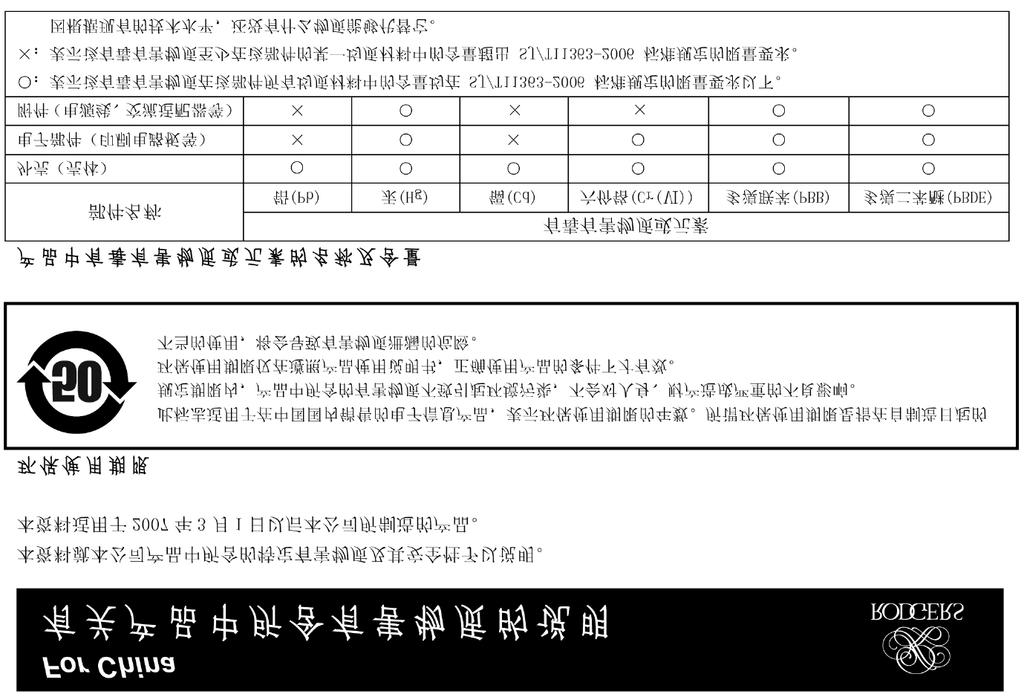
6 CHINESE NOTIFICATION 5
7 Notice to Users Information in this document is subject to change without notice. No part of this manual may be translated into any language, stored in a retrieval system, reproduced or transmitted in any form or by any means, electronic or mechanical, including photocopying and recording, for any purpose without the express written permission of Rodgers Instruments LLC. RODGERS INSTRUMENTS LLC 1300 N.E. 25 th Avenue Hillsboro, Oregon (503) RODGERS IN CANADA 5480 Parkwood Way Richmond, B.C. V6V 2M4 Toll Free Rodgers instruments are manufactured and protected under one or more of the following U.S. patents: 4,622,878, 5,060,179, 5,087,798, 5,091,613, 5,225,619, 5,262,581, 5,508,472, 6,369,310, 6,399,868 Copyright 2008, Rodgers Instruments LLC, a member of the Roland Group, All rights reserved. Printed in the United States of America. QuickMenu, Rodgers, Rodgers Classic Organs, Digital Dynamic Wind, Dimensional Sound Modeling, Parallel Digital Imaging, Voice Palette, DVM, PDI, TrueChimes are trademarks or registered trademarks of Rodgers Instruments LLC, Hillsboro, Oregon. RSS is a registered trademark of the Roland Corporation. 6
8 CONTENTS FCC Notice...3 Radio and Television Interference...3 Contents...7 Introduction...9 Turn On/Turn Off...10 Turning On:...10 Manuals and Pedalboard...10 Activating Stops...10 Intermanual Couplers...11 Intramanual Couplers...12 MIDI Couplers...12 Using Pistons to Select Registrations...13 General Pistons Toe Pistons Divisional Pistons...13 Divisional Pistons...14 General and Divisional Cancel...14 Combination Memory Levels...15 Selecting Memory Levels...15 Console Displays, Indicators, and Menus...15 Locking a Combination Memory...16 Unlocking a Combination Memory...17 Restoring Factory Combination Settings...17 Reversibles...18 Expression Shoes and Controls...18 Crescendo Shoe and Controls...19 Standard and Alternate Crescendo Sequences...19 Great/Pedal Enclosed...19 Great/Pedal Unenclosed...19 Festival Trumpet Enclosed...20 All Swells...20 Transposer...20 Tremulants
9 Tutti...21 Melody Coupler...21 Bass Coupler
10 INTRODUCTION Grand, glorious sound is the hallmark of the Rodgers organ. Providing a rich and spacious ensemble sound complemented by crystal-clear definition, the Rodgers organ will take you to new musical heights, while sustaining the tradition of quality, craftsmanship and innovation you ve come to expect from Rodgers. Dimensional Sound Modeling is the 21st century standard in the art of digital organ building. This technology ushers in a new era of choice and control to create authentic pipe organ sound and room acoustics as never before possible. Dimensional Sound Modeling technology takes you from virtual to reality. With unmatched user control over every major facet of the organ, you can create a sound and an acoustical environment modeled to your taste and musical needs. Rodgers exclusive Voice Palette system allows you to easily access numerous additional sounds. These voices, available as alternate selections behind many stops, greatly expand the tonal resources of the instrument. Each selection can be easily stored in the organ s memory system, allowing you to authentically recreate virtually any musical style or individual performance desired with the push of a button. With remarkable flexibility, superior sound and the option of adding real pipes at any time, the Rodgers organ is a perfect choice for any home, concert or worship setting. Built entirely in Oregon by dedicated, expert craftsmen, our consoles are meticulously handcrafted of hardwoods and veneers, and are designed to the exacting standards of the American Guild of Organists. This manual will help with the exploration of the expansive capabilities and the variety of features and functions offered by this instrument. As highly sophisticated as the Rodgers organ is, the features are easy to use and easy to access, creating a most satisfying musical experience for the player and listener alike. To keep abreast of the latest news and other items of interest, visit the Rodgers website at: Two operational guides are included with the Rodgers organ. Owner s Guide Use this guide to familiarize yourself with the basic operation and functions of the instrument. Advanced Features Reference Guide (referred to in this guide as the AG) This guide provides in-depth descriptions and explanations of the many advanced controls and features of the Rodgers organ.! You ll also find helpful hints and additional details in italics like this. 9
 until it")


11 To get started, here is an overview of the basic operations of the Rodgers organ. Turn On/Turn Off Turning On: Depending on model, press and hold the top of the On/Off rocker switch for approximately 2 seconds and release or press the top of the On/Off switch labeled ( ) until it locks into place. The instrument identification message appears in the display window. The organ then performs a diagnostic test of its systems over the next few seconds. When completed, the display window reads TRANSPOSER 0. The organ is ready to play. Turning Off: Press and hold the bottom of the On/Off rocker switch for no more than 1-2 seconds and release, or press the bottom of the On/Off switch labeled (O) until it locks into place.! Depending on model, the organ may be equipped with an Automatic Shutdown feature. See the AG. Manuals and Pedalboard The organ has keyboards played by the hands, commonly referred to as manuals. Each manual plays an assortment of stops. The group of stops associated with a keyboard is known collectively as a division. The keyboard played by the feet is referred to as the pedalboard, and stops played by the pedalboard make up the Pedal division. Two manual organs contain, in order from bottom to top, the Great Manual, and the Swell Manual. Activating Stops The term Stop is used to describe a single voice or control on an organ. Stops are activated by Rocker Tablets (tabs) and/or Drawknobs. Depending on model, a Stop may also be activated by a piston (i.e. chimes). Stops may be a Speaking Stop (controlling a voice) or a Non-speaking 10


12 Stop (such as a Tremulant or a Coupler). The organ will produce sound if a Speaking Stop is activated and any keys or pedals that control that division are pressed. To activate a stop or control, press the bottom of the tab or pull the drawknob, and release. To deactivate a stop or control, press the top of the tab or push the drawknob, and release.! Many stops have more than one voice to choose from. This is referred to as the Rodgers Voice Palette. See the AG. Couplers Depending on model, different coupler types are available. Intermanual Couplers An Intermanual Coupler is a control that allows a division of the organ to be played from a different manual or the pedalboard. They most often function from tabs located above the Swell manual (also called the tab rail). For example, by activating the Swell to Great 8 coupler, stops selected in the Swell division will play from the Great manual. ( Swell to Great literally means, connect the Swell division to the Great manual ). Intermanual Couplers allow you to control a larger portion of the organ from one manual or the pedalboard and are useful in achieving larger and more varied registrations. The pitch designation (8 and 4 ) specifies the pitch at which the division is to be coupled. 8 is concert pitch in organ nomenclature; when using an 8 coupler, the division is coupled at its normal pitch. 4 pitch is an octave above 8 pitch. When a 4 coupler is used, the division is coupled an octave higher than normal. This nomenclature is similar to the pitch designation used in organ stops. 8 intermanual couplers are commonly used when building large ensemble registrations, whereas 4 couplers are usually not employed. 4 couplers are often used with celeste stops in more gentle registrations; they effectively increase the number of notes that are sounding and increase the warmth and breadth of the ensemble. 11


13 Intramanual Couplers Intramanual couplers are different from intermanual couplers in that they operate within a single organ division. These couplers allow you to play stops of the organ at a different pitch level on the same manual where the stop is located. These couplers are often referred to as Sub Couplers and Super Couplers. For example, by activating the Swell to Swell 16 coupler (Sub), the stops selected in the Swell division will sound one octave lower than the key played on the Swell manual. An exception is the first octave where the lowest 12 notes will only sound at unison pitch. With the Swell to Swell 4 coupler (Super) activated, the stops selected in the Swell division will sound one octave higher than the key played on the Swell manual. An exception is the last octave where the highest 12 notes will not play if the selected stop is 2' or shorter. Another example of intramanual couplers is UNISON OFF. The SWELL UNISON OFF coupler silences notes at concert or unison pitch (hence, the name) on the swell manual. For example, selecting the SWELL UNISON OFF coupler would cause activated stops in the Swell division to be silent even when notes are played on the Swell manual. The Unison Off couplers are useful when you want to couple a division somewhere else without having it sound on its assigned manual (i.e., you want to couple stops in Swell division to the Great but don t want them to play from the Swell manual). MIDI Couplers MIDI couplers, depending on model, are located under their respective manuals on pistons (commonly referred to as thumb pistons) or on rocker tabs located on the tab rail. The couplers labeled MIDI SW A and MIDI SW B for the Swell Manual, MIDI GT A and MIDI GT B for the Great Manual, and MIDI PED A and MIDI PED B for the pedals allow sounds from an external sound module to be played from different divisions of the organ. If the instrument has internal orchestral voices the MIDI couplers will be labeled ORCH/MIDI SWELL or MIDI ORCH SW A and MIDI ORCH SW B for the Swell Manual, ORCH/MIDI GREAT or MIDI ORCH GT A for the Great Manual and ORCH/MIDI PEDAL or MIDI ORCH PD A or MIDI ORCH PD B for the pedals. As such, these couplers are dual function; they can access the self-contained internal orchestral sounds, or control the sounds of an external sound module. 12
 or press the respective MIDI ORCH Piston (SW A or B, GT A or B, or PD A or B). 3.")


14 To assign internal sounds on instruments with ORCH/MIDI couplers: 1. Press and hold the SET piston. 2. Push the lower part of the appropriate ORCH/MIDI coupler tab (Swell, Great or Pedal) or press the respective MIDI ORCH Piston (SW A or B, GT A or B, or PD A or B). 3. Rotate the Alpha dial until the desired sound appears in the display. 4. Press Cancel (0) to exit. The selected sound is now set to play with the MIDI/ORCH tab turned on. 5. This instrument will remember the selected sounds the next time the organ is turned on ONLY if you save your ORCH/MIDI sound settings to a general or divisional combination piston.! For assigning sounds from an external sound module see the AG. Using Pistons to Select Registrations Experiment with various combinations of stops and couplers and start to get a feel for the tremendous versatility of the Rodgers organ. In organ terms, these combinations of stops and couplers are referred to as registrations. Once a desirable registration is found, it can be recalled quickly and easily. This is done using the combination action pistons of the organ. You can store and recall stops, couplers, pistons and even MIDI settings at the touch of a button. General Pistons Toe Pistons Divisional Pistons These pistons are located beneath the manuals of the organ or adjacent to the expression shoes. Pressing a piston will cause its stored registration to be recalled instantly. Each of the available pistons in the Rodgers combination action can be easily changed to suit your particular needs and tastes. The Rodgers organ has two different types of combination action pistons, general and divisional pistons. 13

15 General Pistons General pistons affect all divisions of the organ simultaneously. Up to 10 General pistons are available, depending on model. They are located on thumb pistons under the left-hand side of the Great and Swell manuals. In addition, they may also be duplicated on toe pistons adjacent to the expression shoes. To recall a registration stored on a general piston, you could press either the corresponding thumb piston or toe piston; in other words, to select general piston 3, you could either press thumb piston 3 under the Great manual or toe piston 3. The duplication of pistons allows you to use either your hand or foot to recall the same registration, depending on what is most convenient. Divisional Pistons Divisional pistons affect a single division. There are up to five divisional pistons for the Great and Swell divisions. These pistons are located under the corresponding manual. For example, Great divisional pistons are located underneath the Great manual near the middle of the keyboard. Swell divisional pistons are centered below the Swell manual. Some Rodgers models also feature Pedal divisional pistons. They are located on the toe pistons adjacent to right of the expression shoes. General and Divisional Cancel When TRANSPOSER is displayed in the window, ALL stops, couplers and MIDI settings can be cleared by pressing the General Cancel piston (0). Setting a Piston The Rodgers organ is equipped with factory registrations, each of which can be used for a wide variety of musical effects. However, the contents of any piston can be easily changed to suit your particular needs. To set a new registration on a piston: 1. Select the desired stops, couplers and MIDI settings. 2. Press and hold the SET piston. While continuing to hold SET, press the piston (General or Divisional) to be programmed. 3. Release both pistons. The new registration is now stored for later recall.! A memory level must be unlocked before it can be changed. See below. 14


16 Combination Memory Levels Rodgers advanced combination action systems have up to 100 memory levels depending on model. This effectively multiplies the number of available combination pistons by up to 100. Combinations stored in one memory level don t affect those stored on other memory levels; each memory level is independent. Many organists keep regularly used registrations, such as those used for hymns, on one memory and use other memory levels for preludes, postludes and choral accompaniments, which may change week to week.* *Note: A variety of useful registrations have already been stored when the organ arrives from the factory. Selecting Memory Levels Memory Levels can be selected by pressing the corresponding piston M1, M2, M3, etc. or the pistons labeled M+, or M- depending on model. When M+ and M- are used, the selected memory level appears in the display window. Pistons labeled M1, M2, and M3 etc. will light or display the memory level in the display window. To select a memory level: Press the corresponding memory piston (M1, M2, M3, etc.). The piston will light or press the M+ piston or M- piston until the desired level 1 thru 100 (labeled 0), depending on model, is displayed in the window. In either case, M1 is automatically selected when the organ is turned on.! With Rodgers Memory Card System or USB data port unlimited memory levels are available. See the AG Console Displays, Indicators, and Menus The Rodgers organ is equipped with an informative display for many of the console functions described in this section. The Console Display normally indicates the Transposer setting; however, it can be used to adjust many other controls and preferences including MIDI settings, Voice Palette selections, Dimensional Sound Modeling parameters, Tremulant rate and depth, and many others. 15


17 Two controls are used to select and modify the features found in the Console Display. The smaller knob is the Select knob; it is used to select the menu item to be changed. The larger dial is called the Alpha dial; it is used to change the settings in a selected menu. Most of the features that can be modified in the Console display will follow this pattern: Alpha Dial always the larger dial and changes the selected item Select Knob always the smaller knob and selects the item OR The Alpha dial and Select knob may also be configured and shown below. Locking a Combination Memory When shipped from the Rodgers factory, all memory levels are unlocked so that pistons can be easily changed. If desired, each memory level can be locked individually so that it cannot be changed. On instruments with combination action pistons M1, M2, etc., any memory level can be locked using the following procedure: 1. Press and hold the memory piston (M1, M2, M3, etc.) corresponding to the memory level you want to lock until the memory bank screen appears. Internal or Memory Card and (#) Unlocked or (#) Locked appears in the display. 2. If (#) Unlocked appears, go to step 3. If (#) Locked appears, the memory level is already locked. 3. Turn the Select knob to highlight Unlocked. 4. Rotate the Alpha dial to select Locked. The memory is now locked and that memory level cannot be changed. 5. Press and hold Cancel (0) until Transposer 0 appears in the display. On instruments with the M+ and M- pistons, memory level may be locked using the following procedure: 1. Use M+ or M- pistons to select the memory level to be locked. 2. Press and hold SET then press and release M+. 3. Turn the Select knob to highlight Unlocked. 4. Rotate the Alpha dial to highlight Locked. 5. Press and hold Cancel (0) until Transposer 0 appears in the display. 16
18 Unlocking a Combination Memory On instruments with combination action pistons M1, M2, etc., any memory level can be locked using the following procedure: 1. Press and hold the memory piston (M1, M2, M3, etc.) corresponding to the memory level you want to lock until the Memory Bank screen appears. Internal or Memory Card and (#) Unlocked or (#) Locked appears in the display. 2. If (#) Locked appears, go to step 3. If (#) Unlocked appears, the memory level is already unlocked. 3. Turn the Select knob to highlight Locked. 4. Rotate the Alpha dial to select Unlocked. The memory is now unlocked and that piston can be changed. On instruments with the M+ and M- pistons, memory level may be unlocked using the one of the following procedures: 1. Use M+ or M- pistons to select the memory level to be unlocked. 2. Press and hold SET then press and release M+. 3. Turn the Select knob to highlight Locked. 4. Rotate the Alpha dial to highlight Unlocked. Restoring Factory Combination Settings If the original factory settings have been overwritten or erased, and you would like to restore them, use the following procedure: 1. Press and hold the memory piston to be restored (M1, M2, or M3) until the Memory Bank screen appears. The display shows Memory Bank and Unlocked or Locked (if locked, see the unlocking procedure in the previous section). 2. Turn the Select knob until Restore Factory appears in the display. 3. Press and release SET. 4. Turn the Select knob highlight No. 5. Rotate the Alpha dial to highlight Yes. 6. Press and release SET. 7. Press and hold Cancel (0) until Transposer 0 appears in the display. 8. Power the instrument off and on. The selected memory has been restored to factory defaults. 17
. 3.")
 until Transposer 0 appears in the display. 9. Power the instrument off and on. The selected memory has been restored to factory defaults.")
19 To restore the default setting using the M+ and M-, use one of the following procedures: Reversibles 1. Use M+ or M- pistons to select the memory level to be unlocked. 2. Press and hold SET and press M+. The display shows Memory Bank and Unlocked or Locked (if locked, see the unlocking procedure in the previous section). 3. Turn the Select knob until Restore Factory appears in the display. 4. Press and release Quick Menu. 5. Turn the Select knob highlight No. 6. Rotate the Alpha dial to highlight Yes. 7. Press and release SET. 8. Press and hold Cancel (0) until Transposer 0 appears in the display. 9. Power the instrument off and on. The selected memory has been restored to factory defaults. Rodgers organs are equipped with a number of reversible controls, so named because pressing them once will activate the function, pressing them again will deactivate the function. These reversibles, located on thumb and toe pistons, are especially useful in a performance when you want to quickly activate or remove a single coupler, stop or other setting. For example, the Great to Pedal coupler piston is a reversible. Press the thumb or toe piston to turn on, and press again to turn off. All reversible thumb pistons light when activated. Expression Shoes and Controls Depending on model, Rodgers two manual organs have one or two Expression Shoes or two Expression Shoes and a Crescendo Shoe used to control the volume and registration of the organ. Additionally, depending on the model, the right expression shoe may have the dual function of being an expression shoe or may be switched to perform as a Crescendo Shoe. If this is the case, the organ will have a tab or piston labeled Crescendo to change the functionality. 18
20 When the expression shoe is pressed forward, the volume of the division is increased. When the shoe is drawn back, the volume of the division decreases. The positions of the two expression shoes are displayed on two expression indicators. Crescendo Shoe and Controls Depending on model, the Crescendo shoe is slightly raised and to the far right. This shoe gradually adds a predetermined selection of stops as it is pressed forward. It does not affect the stops already in use on the organ but merely adds to them as the Crescendo is activated. Closing the Crescendo shoe subtracts the stops in reverse order. Stops added by the Crescendo shoe do not indicate they are activated. In organs equipped with a crescendo function there will be a Crescendo indicator showing the position of the Crescendo shoe. Standard and Alternate Crescendo Sequences All Rodgers organs are equipped with a Standard Crescendo sequence that is classical in nature. Depending on model, an Alternate Crescendo sequence, more romantic in nature, may also be available. The Standard Crescendo sequence is available when the organ is first turned on, and anytime the ALT CRESC piston is unlit. Pressing the ALT CRESC reversible piston so that it lights engages the Alternate Crescendo sequence.! The Standard and Alternate Crescendo sequences can each be reprogrammed to use a different sequence of stops. See the AG. There are also a number of very useful features that allow you to modify the way the organ is expressed (i.e., how the volume is controlled). Each of these particular controls is activated by a thumb piston, which can be set in a general combination. If the thumb piston is lit, the control is activated. Great/Pedal Enclosed On some Rodgers organs the Great and Pedal divisions are unenclosed; that is, their volume is unaffected by movements of the expression shoes. This allows the organist to change the volume of the Choir, Swell and Solo divisions while the volume of Great and Pedal divisions remains constant. There are times, however, when it is desirable to have the Great and Pedal divisions under expression, that is, affected by movement of the expression shoes. When activated, the GT PED ENCL piston is lit, and the Great and Pedal divisions change to enclosed; that is, their volume is now controlled by the Choir expression shoe. Great/Pedal Unenclosed Other Rodgers models feature Great and Pedal divisions that are enclosed; that is, their volume is affected by movements of the expression shoes. This allows the organist to change the volume of the Choir, Swell and Solo divisions as well as the volume of the Great and Pedal divisions. There are times, however, when it is desirable to have the Great and Pedal divisions unenclosed; that is, not affected by movement of the expression shoes. When activated, the GT PED 19
21 UNENCL piston is lit, the Great and Pedal divisions change to unenclosed and their volume is no longer controlled by the Choir expression shoe. Festival Trumpet Enclosed In the same way, the Festival Trumpet 8 and solo reeds (FFF) are normally unenclosed; that is, not affected by the expression shoes. However, when the FEST TR ENCL (may be engraved as FFF REEDS ENCL) piston or tab is activated, the Festival Trumpet 8 and the other FFF reeds stop are enclosed and will be expressed by the appropriate divisional shoe. All Swells There are times when it is desirable to use a single expression shoe to control all divisions under expression. When the ALL SWELLS piston is lit, the Choir, Swell and Solo divisions are all assigned to the Swell expression shoe, allowing you to easily control the volume of every enclosed division.! If ALL SWELLS, GT-PD ENCL and FEST TR ENCL (FFF REEDS ENCL) are all activated, the entire organ is enclosed and can be expressed by the Swell expression shoe. In organs with the Crescendo Tab or Piston to change the function of the right expression shoe to Crescendo, the organ will change to ALL SWELLS and all expression will be controlled by the left shoe. Transposer The Transposer allows you to change the key of music played. Commonly, this is used to accommodate a soloist or instrumentalist who prefers accompaniment in a different key than what is written or to easily raise or lower the pitch of a hymn. The Transposer position is normally shown in the Console Display. If another screen appears in the display (i.e., while programming a specific parameter), you can easily return to the Transposer by pressing the General Cancel (0) or STOP thumb piston until TRANSPOSER appears in the display. Turning the Select knob while TRANSPOSER 0 is displayed lowers or raises the pitch of the organ. Rotating the Select knob clockwise raises the pitch of the organ by semitones; rotating counter-clockwise lowers the pitch by semitones. Pressing General Cancel returns the Transposer to 0, (no transposition). Tremulants Tremulants create a change in pitch (sharp and flat), amplitude (volume) and phase (variations in the sound wave front). Rodgers organs use a complex model to emulate the tremulant effect of a pipe organ. The use of the tremulant adds warmth and expressiveness to solo or small ensemble combinations. It is not common to use tremulants in larger classical ensembles. In some romantic ensembles, tremulants are used judiciously. In some gospel and evangelical musical traditions, tremulants with a wider and deeper excursion are frequently used. There are two types of tremulant controls available on Rodgers organs, divisional tremulants that affect only the stops in their respective division and general tremulants that affect all divisions. 20
22 If there is a Solo division on the organ, up to four divisional tremulants may used. One each for the Great, Swell, and Solo; the first three are controlled by a tab or drawknob within each division, while the Solo tremulant, if applicable, is located on a thumb piston. Some models also feature up to two additional general tremulants, Main Tremulant II and Flute Tremulant II. They will be located on thumb pistons labeled MAIN TREM II and FLUTE TREM II. Both of these tremulants find their best use in gospel, theatre and evangelical music; the Main tremulant affects Principal, String and Reed voices whereas the Flute tremulant affects only Flute voices. Divisional tremulants can be stored with registrations in both general and corresponding divisional pistons; general tremulants can only be stored on general pistons. Tutti! Each tremulant effect can be modified easily to suit your tastes and needs. See the AG. There are times when a full organ registration is needed immediately. A Tutti control allows you to engage full organ quickly without canceling your set registration. Activate the control by pressing the TUTTI thumb piston or toe stud; press again to turn off Tutti and return to the current registration. When Tutti is activated, the Tutti indicator located directly above the Crescendo indicator is lit. Pressing General Cancel (0) will also cancel Tutti. TUTTI comes programmed from the Rodgers factory.! Tutti can be reprogrammed, if desired. See the AG. Melody Coupler One of the most popular organ registrations utilizes a melody voice on one manual and accompaniment on another manual. Sometimes, however, it is difficult to separate the hands on two manuals. For this reason, the Rodgers Melody coupler was devised. When a Melody coupler is activated, the highest note played on the Great manual uses a registration from the Swell manual. This allows you to have both an accompaniment and solo registration, even though you re playing on one manual. This coupler is located on thumb pistons under the Great manual labeled MEL SW or on a tab labeled SWELL MELODY ON GREAT. This piston or tab lights when activated. When the Melody from Swell is activated any selected stop or MIDI voice in the Swell division sounds from the highest key being played on the Great manual. Melody couplers should be used when the corresponding intermanual coupler is not engaged. For example, when Melody from Swell is activated, the Swell to Great couplers should not be used to achieve the proper Melody affect.! Note: An exception to this rule is when using Orchestral voices, which do not couple with the Intermanual coupler. With an Orchestral voice in combination with the Swell 21
23 organ voices, the Swell organ voices can be coupled with the SW to GT coupler, and the top solo note of the Orchestral voice can be coupled to the Great with the MEL SW coupler. This is useful when using a strong orchestral voice, such as the Trumpet. In its default setting, the Melody Coupler operates when the top note (the melody note) is between keys 25 and 61 on the Great manual. The lower end of its range is programmable and may be extended down to key 13 or up to key 49. See the AG.! Melody Couplers can be set only in General combination pistons. Bass Coupler The Bass coupler is much like the Melody coupler described above, except that it adds the Pedal registration to the lowest note played on the Great manual. This allows you to easily add a Pedal part to anything played on the Great manual. The BASS coupler is located on a thumb piston beneath the Great manual or on a tab labeled BASS ON GREAT. When activated, the piston or tab lights, and any selected registration in the Pedal division will sound from the lowest key being played on the Great manual. This provides a pedal bass sound without actually playing the pedalboard. In the default setting, the Bass Coupler affects keys 1 through 24 of the Great manual, but its range can extend up to key 32 (top of the pedalboard range). See the AG.! The Bass Coupler can be set only in General combination pistons 22
24 P/N
25 Advanced Features USER S GUIDE
26 Table of contents Using the Advanced Features Guide...1 Console Displays, Indicators, and Menus...1 QUICK MENU... 1 Changing a Setting with QUICK MENU... 2 Console Menu Map... 2 Master Tuning...3 Unlocking Master Tuning... 3 Adjusting Pitch... 3 Creating New Crescendo Sequences...4 Unlocking and Locking the Crescendo Sequences... 4 Setting a New Crescendo Sequence... 5 Deleting Crescendo Sequences... 6 Restoring Factory Crescendo Sequences... 6 Crescendo and Tutti Blinds...7 Tremulant Controls...7 Adjusting Tremulant Settings... 8 Tutti Settings...9 Unlocking or Locking Tuttis... 9 Viewing Tutti Setting... 9 Setting a Tutti Registration Restoring Factory Tutti Settings Melody and Bass Couplers...10 Setting the Range for Melody and Bass Couplers Melody Couplers Bass Coupler Antiphonal On/Main Off (Alternate Audio A/Alternate Audio B)...11 Digital Zimbelstern...12 Adjusting Digital Zimbelstern Rate and Randomness Choir/Great Transfer...12 Controlling Pipes...13 Pipes Off/Ancillary On Automatic Shutdown Timer...14 Song Record/Playback...14
27 Recording a Song Discarding a Song in the Organ s Internal Memory Saving a Song to the Memory Device Playing a Song Saved on the Memory Device The [Sequencer Manage] Menu Deleting a Song from the Memory Device Metronome...16 Adjusting the Metronome Memory Devices - Rodgers Memory Card/USB Flash Drive...17 Inserting a Memory Card or Flash Drive Saving to a Memory Device Saving registrations to a memory device Memory Card/USB Folders Selecting a Memory Card/USB Folder Storing Crescendo Sequences and Tutti Settings on a Memory Device Deleting a Crescendo Sequence from a Memory Device Deleting a Tutti Sequence from a Memory Device Storing Additional Settings on a Memory Device Deleting Additional Settings from a Memory Device Deleting a Memory Level from a Memory Device Pipe Modeling...21 Temperaments Ancient Temperaments Well Temperaments Selecting a Temperament Digital Dynamic Wind Wind Supply Adjusting Wind Supply Shutter Thickness Setting Shutter Thickness Random Detuning Voice Palette...26 Making a Voice Palette Selection Resetting Voice Palette Selections The Amens/Alleluias Stop...27 Master Volume Control...28 ii
28 Adjusting Master Volume Audio Save...28 Saving Audio Control Settings Headphone Jack...29 Adjusting Headphone Settings Auxiliary Controls...29 Adjusting Auxiliary Inputs Aux Amb Level Aux Input Audio Routing (Send to:) Orchestral Input Audio Routing (Send to:) Room Modeling...32 Adjusting Room Modeling Settings Console Settings...33 Adjusting Console Settings MIDI (Musical Instrument Digital Interface)...34 MIDI Basics MIDI Connections Connecting a MIDI Sequencer Connecting a MIDI Sound Module Connecting a Remote Keyboard General MIDI (GM) Note ON/Note OFF messages Control Change Messages GS Standard GM2 Standard MSB and LSB Messages MIDI Coupler Settings Selecting a MIDI Coupler for programming using MIDI using the shortcut method Tone Selecting Tones by Name Previewing Tones by Name Selecting Tones by Number Selecting Tones using the Quick Key Method Saving MIDI Coupler Sounds and Settings to a Combination Piston Setting New MIDI Coupler Defaults (MIDI Save ) MIDI Channel iii
29 Changing the Great MIDI Channel Octave Shift Shifting the Octave of a MIDI Coupler Velocity Fixed Velocity Expression Velocity Keyboard Velocity Pan Setting the Pan value for a MIDI Coupler Sustain/Sostenuto/Soft Enabling/Disabling a Foot Switch Function for a MIDI Coupler Reverb Setting the Reverb Level for a MIDI Coupler Chorus Setting the Chorus Level for a MIDI Coupler Expression Setting the Expression/Volume Parameter for a MIDI Coupler Volume Setting Volume for a MIDI Coupler Tone Names Setting the Tone Names Parameter for MIDI Coupler All Notes Off Command Global MIDI Settings...51 Master Channels Enabling or Disabling a MIDI Master Channel Registrations Selecting MIDI Registration Settings Multitrack Mode Turning Multitrack Mode On or OFF Local On/Off Selecting the Local Control Setting: Sequencer Update Turning Sequencer Update On or Off: Setting Keyboard Velocity Sensitivity Setting the Keyboard Velocity Sensitivity MIDI Device ID Setting MIDI Device ID iv
30 MIDI Tone Name File Select Mode Setting MIDI Tone Name File Select Mode Memory Bank...59 Scrolling to a Memory Level Archiving Combination Memories to a MIDI Sequencer...59 Saving a Combination Memory to an External Sequencer Restoring a Combination Memory from an External Sequencer Preferred Shortcuts...61 Audio Maps...61 Demonstration Tools...61 Playing the Demo Songs To store recorded songs on a memory device: To play songs stored on a memory device: The Rodgers Ambience Demo Controlling a Rodgers Organ from another Console or MIDI Keyboard...63 Establishing a Rodgers Organ or Keyboard as a Master Controller Establishing a Rodgers Organ as a Slave Controlling a MIDI Keyboard from the Rodgers Organ Care and Maintenance...64 Console and Pedalboard Keyboards, Drawknobs, and Stop Tabs Pipes on Pipe-Augmented Instruments Appendix A...1 Menu Hierarchy... 1 Root Menus... 1 Sequencer Record/Playback/Manage and Metronome... 1 MIDI Menus... 2 Audio Control Menus... 3 Pipe and Room Modeling Menus... 4 Crescendo, Tutti and Console Menus... 5 Appendix B - -MIDI Program Changes for remote Piston Control...1 Index... I v
31 ADVANCED FEATURES USER S GUIDE The following sections present the capabilities of the RODGERS organ in greater detail. This manual enables users to become more familiar with the many innovative features of their Rodgers instrument. Using the Advanced Features Guide This guide is arranged in the order of the console menu structure as much as possible. Although every attempt has been made for accuracy, features will vary from model to model, and between software versions. Custom organs may vary in specification considerably from the features encompassed in this guide. Additionally, features may change and new features may be added in future software revisions. The manual includes a number of hints, which are introduced by a bold exclamation! and are in italic text. Console Displays, Indicators, and Menus The following section describes how the console display is used, outlines the basic navigation technique and gives you a map of what features can be found and adjusted by the organist. After that introduction, each feature and control found in the display will be described in more detail. QUICK MENU With the incredible number of features contained within the instrument, a system was needed which would provide quick, easy access. Rodgers exclusive QUICK MENU is the answer. QUICK MENU offers simple, direct access to a myriad of features and functions. These functions are arranged in a logical hierarchy, beginning with broad categories and continuing with menus that are functionally subordinate. To access a particular control or feature of the Rodgers organ, go first to the appropriate category and then access the desired menu from a list and then change the setting as desired. The first level of the QUICK MENU hierarchy contains categories; for example, MIDI Settings, Pipe Modeling, and Room Modeling. The next level of the hierarchy contains a list of the names of menus that are functionally related to a selected category. The third level of the hierarchy displays a menu item with a user settable field. Graphically, the QUICK MENU hierarchy can be represented this way:
32 Category MIDI Settings Pipe Modeling Room Modeling. Names of Menus Item (Rotate Alpha Dial to Change Setting) Category and Menu Hierarchy Now that you have an idea about how the menus are organized, we ll discuss how to navigate through the menus using the QUICK MENU piston, the Select Knob and the Alpha Dial. Later in this manual, establishing shortcuts to reach these menus will be discussed. Changing a Setting with QUICK MENU To use QUICK MENU to view or change settings: 1. Press and release the QUICK MENU piston. 2. Turn the Select Knob to select a desired category (it becomes highlighted). 3. Press and release the QUICK MENU piston. Menu items related to the selected category will be displayed. 4. Rotate the Select Knob to display a particular menu name or item. 5. Rotate the Alpha Dial to change the setting. Press the General Cancel (0) piston to exit a selected item and return to the previous stage in the hierarchy, or press and HOLD the General Cancel (0) piston for about 2 seconds until TRANSPOSER 0 appears in the display.! Note: The display must show TRANSPOSER 0 before you can use the CANCEL (0) piston to clear activated stop selection. Console Menu Map Appendix A is a listing of the parameters and controls that can be accessed and changed. (As Rodgers Organs are made to custom specifications, all menus are not available on all instruments, and may further depend on the exact version of operating software used by the organ). Use the table of Appendix A to familiarize yourself with the wide variety of controls available to you and see where they are located within the menu system. 2
33 Each of the parameters and controls contained in the hierarchy of Appendix A is discussed later in this section of the manual; the table of Appendix A is included to give you a road map of the many controls available to you. Master Tuning Normally, the organ is set to standard concert pitch (A=440.0 Hz) when the tuning control is Locked. However, it can easily and quickly be tuned flat or sharp to match the pitch of another musical instrument, such as a piano or harp. The Master Tuning control will also adjust the pitch of an external MIDI device, which recognizes Roland GS format tuning messages, such as the Rodgers MX-200 sound module. The Master Tuning control adjusts tuning either one-half semitone sharp or flat (427.3 to 452.7HZ) or one full semi-tone sharp or flat (415.3 to 466.2HZ), depending on model and software version. In instruments augmented with pipes, the Master Tuning feature is used to bring the electronics in tune with the pipes. Normally, the Master Tuning control is locked and the Transposer is the only parameter in the default display. However, when the Master Tuning control is unlocked, both the Transposer and Master Tuning settings appear in the display; each can be easily changed. Unlocking Master Tuning To unlock Master Tuning and allow it to be changed: 1. Press and release the QUICK MENU piston. 2. Turn the Select Knob clockwise until the Console category shows on the display. 3. Press and release the QUICK MENU piston to select the Console category. 4. Turn the Select Knob clockwise until Master Tuning appears. 5. Press and release the QUICK MENU piston to select Master Tuning. 6. Rotate the Alpha Dial to select either Adjustable or Manual Only. Either of these selections will unlock the Master Tuning control. 7. Hold SET and press General Cancel (0) until User settings saved. appears in the screen to save your changes as new start-up defaults.! The difference between Adjustable and Manual Only Master Tuning settings is that in the Adjustable setting, pitch can be adjusted at the console or via an external MIDI device connected at the Pipe Port (such as the pipe auto-tuner ). In the Manual Only setting, pitch can be adjusted only from the console Alpha Dial (see below). Adjusting Pitch Once the Master Tuning control has been unlocked, you can change the pitch of the Rodgers organ (and a Roland GS compatible external MIDI device) by rotating the Alpha Dial clockwise to raise the pitch or counterclockwise to lower the pitch.! The pitch displayed in the display at the time the organ is turned off will be retained in memory (as long as the setting of Adjustable or Manual Only has been saved to memory 3
34 first). When the organ is started again, it will return to the remembered pitch (and send a corresponding tuning message to an externally connected MIDI device).! The Transposer function is still controlled by the Select Knob whenever the Transposer screen is displayed. Creating New Crescendo Sequences Some Rodgers models feature two Crescendo sequences, a Standard sequence as well as an Alternate sequence. One or both of these sequences can be changed to suit your particular needs. The sequences can also be returned to the factory default settings if desired. Crescendo sequences have a total of 64 stages, or steps. Stage 1 is the very first stage activated when the Crescendo pedal is pressed slightly forward. As the pedal is opened further, the Crescendo moves sequentially through the stages until the pedal is completely open and stage 63 is reached. When creating a new crescendo setting, it is advisable to first write the new sequence down, assigning stage numbers from 1 to 63 to each stop or group of stops in the sequence. Sometimes, there are more stages than stop additions or changes in the sequence. If this is the case, just skip some stages to make the sequence end at or near stage 63. If this is not done, the sequence ends before the Crescendo shoe is fully open. Each stop can be turned on at any stage and turned off at any later stage. If a stop is selected at a particular stage, it will sound when the Crescendo is used and reaches that stage. If a stop is retired at a later stage, it will be silenced when the Crescendo sequence reaches that stage. As an example, assume the SWELL 8' BOURDON is to turn on at stage 4 and off at stage 25. At stage 4, you would select the SWELL 8' BOURDON; at stage 25, you would turn it off.! Please note that the crescendo sequences are not Voice Palette specific. When a stop is activated in a crescendo sequence, the currently selected Voice Palette is engaged. To reset Voice Palettes to their power on default setting, refer to Resetting Voice Palette Selections on page 26. Unlocking and Locking the Crescendo Sequences The Crescendo sequences are normally locked to prevent accidental changes and must be unlocked before a new sequence can be set. You should lock the Crescendo sequences after you are finished programming to prevent inadvertent changes. To unlock or lock the Crescendo sequences: 1. Press QUICK MENU. Scroll to Crescendo Seq in the display using the Select Knob and press QUICK MENU again. 2. Rotate the Select Knob to highlight the Lock Sequence item. 3. If the instrument has the capability for both Standard and Alt Crescendo sequences, press the ALT CRESC piston if the Alt Crescendo is to be unlocked. Otherwise, verify the display shows Sequence Std. 4
35 4. If the desired setting (Unlocked/Locked) is already selected, press the General Cancel (0) piston once to exit this menu level. If you wish to change the setting, continue to step Rotate the Alpha Dial in either direction to change the setting. 6. Press the General Cancel (0) piston once to exit this menu level.! This is a sticky setting and will be retained when power is turned off. Ensure the setting is returned to locked to prevent accidental over-writing of the sequence! Setting a New Crescendo Sequence Both the Standard and Alternate (for organs so equipped) Crescendo sequences can be programmed as the organist desires. To set a new Crescendo sequence, first make sure the Crescendo sequences are unlocked using the procedure above. Please note, if the organ has an ALT CRESC piston, and it is unlit, the Standard Crescendo will be selected for programming; if the ALT CRESC piston is lit, the Alternate Crescendo will be selected for programming. In other words, the Crescendo that is selected by way of this piston will be the one modified. To set a new crescendo sequence: 1. Verify the sequence to be programmed is Unlocked 2. Press QUICK MENU. 3. Scroll to Crescendo Sequence in the display using the Select Knob. 4. Press QUICK MENU. 5. Select Crescendo Set and press QUICK MENU. Note: The crescendo selected for programming is shown via the Mode Std or Mode Alt of the display. 6. Verify Stage 1 is highlighted. If another stage is displayed, use the Alpha Dial to select 1. Note: Stage 1 should be a blank stage. 7. Verify no stops or couplers currently set on Stage Make changes to stage 1, if needed, and press SET to proceed to stage 2. Note: any changes made to Stage n are automatically saved when the SET piston is pressed to move to Stage n+1. Using the Alpha Dial to scroll to the next stage will NOT save changes! 9. Add or subtract stops at each stage as desired and press SET to step to next stage. Continue this process until the end of the sequence is reached or you re finished making desired stop changes. Remember: To add a stop or combination of stops to the sequence, go to the desired stage, select them and press SET. 5
36 To delete a stop or combination of stops from the sequence, go to the first stage, in which the stop or stops are activated, turn them off, and press SET. To proceed to the next stage without adding or subtracting stops or couplers, simply press SET. 10. The current sequence may be viewed by advancing through the stages one at a time using the Alpha Dial. At each stage, the stage number (1 to 63) is indicated in the console display, and the stops and couplers set at the selected stage turn on. 11. To exit the Crescendo Set Mode menu at any time, press the General Cancel (0) piston. Any changes in the sequence saved by pressing the SET piston up to that point are retained.! Be sure to re-lock the crescendo lock when finished to prevent accidental erasure or over-writing of the sequence! Deleting Crescendo Sequences To delete a crescendo sequence (and start over completely), perform the following: 1. Verify the sequence to be programmed is Unlocked (see Unlocking and Locking the Crescendo Sequences). Note: the menu item will not appear unless the Crescendo lock is unlocked. 2. Press Quick Menu. 3. Scroll to Crescendo Seq in the display using the Select Knob. 4. Press QUICK MENU. 5. Select Delete seq and press QUICK MENU. 6. Rotate the Alpha Dial to yes then press SET. Restoring Factory Crescendo Sequences If desired, the Standard and Alternate Crescendo sequences can be returned to their factory default settings. To return the Standard and Alternate Crescendo sequences to factory settings on instruments with an ALT CRESC piston (if there is no ALT CRESC piston skip to the next section): 1. Make certain the Crescendo sequences are unlocked (see Unlocking and Locking the Crescendo Sequences). 2. Press and hold the ALT CRESC piston for approximately five seconds until the display reads Crescendo Unlocked. 3. While continuing to hold ALT CRESC, press and hold SET. After an additional five seconds, the Console Display reads Crescendo Factory Default. 4. Release both pistons. The Crescendo sequences are now returned to their factory settings. You may want to lock them again to prevent accidental changes. 6
37 To return the Standard Crescendo sequence to factory settings on instruments with no ALT CRESC piston: 1. Make certain the Crescendo sequences are unlocked (see Unlocking and Locking the Crescendo Sequences). 2. Press and hold the SET piston 3. Continuing to hold SET, and press the GT/PED UNENCL piston for several seconds until the follow messages are seen. 4. load factory default will briefly appear. factory default completed then briefly appears indicating that restore was successful. The Crescendo sequences are returned to their factory settings. You may want to lock them again to prevent accidental changes. Crescendo and Tutti Blinds In some organ designs, the Crescendo and Tutti is visible (i.e., the stop(s) in use can be seen via lighting or movement when the Crescendo Shoe is moved). To set the Crescendo and Tutti so that the sequence is always visible (i.e., just as when setting a sequence) perform the following: 1. Press Quick Menu. 2. Select Console with the Select Knob. 3. Press Quick Menu. 4. Select Blinds with the Select Knob. 5. Press Quick Menu. 6. Rotate the Alpha Dial to select visible (for lighted drawknobs or tablets) or operate (for moving drawknobs or tablets), or blind (no lighting or movement of drawknobs or tablets) as desired.! Normally, these settings are temporary and are lost when the organ is powered off. If it is desired to save these parameters, perform the User Save procedure. Tremulant Controls The Owner s Guide describes how tremulants are activated, what stops they control and how they are often used. Another impressive feature of the Rodgers organ is the User-Adjustable Tremulants. Although the tremulants are carefully set at the factory and adjusted when the organ is voiced, each may be modified for rate and depth by the organist to meet a particular musical need or suit an individual taste. Tremulants can be adjusted individually. This allows you to custom-tailor a tremulant for a specific family of stops without affecting the rest of the stops in the division. This tremendous flexibility is a dramatic improvement over other designs, in which a single tremulant controls an entire division (sometimes, the entire instrument). Following is a typical list of tremulants that can be easily adjusted, the stops they control, and how they are activated. 7
38 Division Tremulant Stop(s) Affected Comments Great Main Principal, Reed and String Activated when Great Tremulant is selected Main II Principal, Reed and String Activated when MAIN TREM II is selected Flute Flute Activated when Great Tremulant is selected Flute II Flute Activated when FLUTE TREM II is selected Swell Main Principal, Reed and String Activated when Swell Tremulant is selected (except Voix Humaine 8 ) Main II Principal, Reed and String Activated when MAIN TREM II is selected (except Voix Humaine 8 ) Vox Voix Humaine 8 Activated when Swell Tremulant is selected Flute Flute Flute II Flute Activated when FLUTE TREM II is selected Tibia Tibia Activated when Swell Tremulant is selected Choir Main Principal, Reed and String Activated when Choir Tremulant is selected Main II Principal, Reed and String Activated when MAIN TREM II is selected Flute Flute Activated when Choir Tremulant is selected Flute II Flute Activated when FLUTE TREM II is selected Tibia Tibia Activated when Choir Tremulant is selected Solo Main Principal, Reed and String Activated when Solo Tremulant is selected (except English Horn 8 ) Main II Principal, Reed and String Activated when MAIN TREM II is selected Eng Hn English Horn 8 Activated when Solo Tremulant is selected Tibia Tibia 8 Flute Flute Flute II Flute Activated when FLUTE TREM II is selected Adjusting Tremulant Settings To change the rate and depth for a tremulant: 1. Determine the tremulant to be adjusted from the table above. 2. Press and hold the SET piston. 3. While continuing to hold SET, activate a tremulant control (i.e., the tremulant control in the Great, Swell, Choir). 4. Release the SET piston. 5. If the tremulant you want to change is already selected in the display go to step 6. If not, use the Select Knob to highlight the Tremulant name (i.e., SW Main), then rotate the Alpha-Dial until the tremulant you want to change is shown in the display. 6. Turn the Select Knob and highlight the value for Depth or Rate. 7. Rotate the Alpha Dial until you achieve the desired result. You can preview your changes by selecting a corresponding stop and playing a note while making an adjustment. 8
39 Tutti Settings 8. To save these settings, hold SET and press General Cancel (0) until Dealer & User settings saved appears in the screen. The flexible control system of the Rodgers organ allows you to easily view and change the contents of Tutti if desired. In addition, you can always restore the Tutti contents to factory defaults.! Please note that the tutti registrations are not Voice Palette specific. When a stop is activated in a tutti registration, the currently selected Voice Palette is engaged. To reset Voice Palettes to their power on default setting, refer to Resetting Voice Palette Selections on page 26. Unlocking or Locking Tuttis The Tutti control is usually locked to prevent accidental changes. Before it can be programmed, it must be unlocked. After Tutti has been changed, it s also a good idea to lock it again. To unlock or lock Tutti: 1. Depending on model, press and hold the TUTTI piston for approximately five seconds until locked or unlocked appears in the console display or press Quick Menu and select the Tutti Lock menu item with the Select Knob and press Quick Menu again. 2. If desired setting (Unlocked/Locked) appears in the display, release the Tutti piston. Otherwise, go to step Rotate the Alpha Dial in either direction to change the setting.! Note: The Tutti lock is sticky and changes to the setting will save automatically when the organ is turned off. Viewing Tutti Setting Normally, stops stored in a Tutti do not light or move when the Tutti control is selected (unless visible or operate has been set in the Blinds function). To view all stops and couplers stored in Tutti (when Blinds are set to blind ): 1. Press and hold the TUTTI piston. 2. While holding the piston, press SET. The stops and couplers contained in the Tutti will activate.! Caution: Pressing these pistons in the reverse order will erase or over-write the existing Tutti combination if the Tutti is Unlocked! 9
40 Setting a Tutti Registration To create or change the tutti registration: 1. Make certain Tutti is unlocked. 2. Select the contents of the Tutti for viewing (see above): 3. Make changes to or select the desired stops in the registration. 4. Press and hold SET and press the TUTTI piston. 5. Press General Cancel (0) for about 2 seconds to return to the Transposer menu.! Re-lock the Tutti to prevent accidental changes! Restoring Factory Tutti Settings The factory defaults for Tutti are stored within the instrument even if the Tutti settings have been changed. Because of this, the Tutti can be restored to its original factory setting if desired. The following procedure restores Tutti to its factory default state. To reset Tutti settings to factory default: 1. Unlock the Tutti to be reset (i.e., Tutti I or Tutti II). 2. Press and hold TUTTI. After five seconds, the console display reads Tutti Unlocked. Continue to hold TUTTI until Factory Defaults Loaded appears in the display. 3. While continuing to hold the Tutti piston, press and hold SET for an additional five seconds. The console display reads Tutti Factory Default when the Tutti is reset. 4. Release the piston(s).! Re-lock the Tutti to prevent accidental changes! Melody and Bass Couplers The function of the Melody couplers is to allow coupling of only the TOP NOTE in the combination of notes being played on the Great keyboard from another keyboard (normally from the Swell or Choir) for melody line reinforcement. This feature ALSO couples the top note of any MIDI sounds from that keyboard. Thus, it is possible to add even more MIDI sounds as top note layers to any MIDI sounds already in use on the Great keyboard. See the MIDI Coupler Settings section on page 37 in this guide. Likewise, the Bass coupler allows playing single Pedal division notes (including those provided by the PED MIDI couplers) on the Great keyboard. 10
41 Setting the Range for Melody and Bass Couplers The range of these couplers may be changed to suit their specific purpose in a song. The Melody coupler operates over a specific range of notes from key 25 to key 61 on the Great manual. The bottom note of this range can be moved upward from note 25 as desired to change the range. Similarly, the range of the Bass coupler starts at key 1 and extends to key 32 on the Great manual; the top note of this range may be changed (the default is normally note #24). Melody Couplers To change the range of a Melody coupler: 1. Press and hold the SET piston, then press MEL SW or MEL CH. The Melody coupler will begin flashing and the Melody coupler screen will appear showing the existing bottom note. 2. Release both pistons. 3. While the Melody coupler continues to flash, press a key on the Great manual corresponding to the lowest note of the new range. Any note from key 13 to key 49 may be selected. After the selected key has been pressed, the Melody coupler will turn off and the screen will return to Transposer 0. Bass Coupler To change the range of the Bass coupler: 1. Press and hold the SET piston, then press the BASS piston. The coupler will begin flashing and the BASS coupler screen will appear showing the existing top note. 2. Release both pistons. 3. While BASS is flashing, press a key on the Great manual that corresponds to the highest note the range is to extend. Any note from key 1 to key 32 may be selected. After the selected key has been pressed, the BASS piston will turn off and the screen will return to Transposer 0.! Note: When a key is pressed to set the range, no sound is heard even if stops are on, so no disturbance is made if programming during a performance. The new range of these couplers is remembered when the organ is powered off. Antiphonal On/Main Off (Alternate Audio A/Alternate Audio B) Rodgers feature controls that can operate additional speaker systems, or can map various audio parameters or ambience settings to suit varying situations. If your instrument is equipped with an antiphonal speaker system, depending on the model, the ANT ON and MAIN OFF controls can be programmed to activate the external system or engage other effects (see the section on Maps in this guide). By default, MAIN OFF normally silences the main organ system (including pipes) and ANT ON activates additional Antiphonal Audio Channels. An antiphonal speaker system is so named because it is normally installed a substantial distance from the main organ. This difference in physical placement allows for a variety of effects. 11
42 For example, activating ANT ON and MAIN OFF normally will cause the entire instrument to be heard through the antiphonal speaker system only. Activating ANT ON alone normally means the organ will be heard through both the main and antiphonal organs. Many options and configurations are available to suit any situation. Refer to the section detailing Audio Maps on page 61 for more information on these features, or contact your authorized Rodgers dealer for more detailed information on implementing more of these capabilities, or adding additional amplifiers and speakers to expand the possibilities! Digital Zimbelstern Your Rodgers organ may have a digital Zimbelstern (bell star), a percussive device activated by a lighted reversible piston labeled ZIMBEL or ZIMB located on a piston rail. Press the piston to activate the Zimbelstern; press it again to turn it off. Depending on the model, the Zimbelstern can be adjusted to suit your particular needs. Two adjustments exist for the Zimbelstern: Rate and Depth (Randomness). Rate specifies how quickly the bells are struck; Randomness controls the amount of variation that occurs as subsequent bells are struck the greater the Randomness, the more variation in how bells are struck. Adjusting Digital Zimbelstern Rate and Randomness To adjust Zimbelstern Rate and Randomness: 1. Press and release the QUICK MENU piston. 2. Rotate the Select Knob to highlight Pipe Modeling. 3. Press QUICK MENU to select the Pipe Modeling category. 4. Rotate the Select Knob to highlight Tremulants. 5. Press QUICK MENU to select the Tremulants category. 6. Rotate the Alpha-dial to select GT ZIMB (it is located at the end of the list of available tremulants). 7. Rotate the Select Knob to highlight the desired field Randm: or Rate: then use the Alpha Dial to change the value of the selected field. 8. To save these Zimbelstern values, hold SET and press General Cancel (0) until Dealer & User settings saved. appears in the display. Choir/Great Transfer Available on many three, four and five-manual Rodgers instruments, this control finds use mainly in French organ literature. French organ design places the Great division (Grand Orgue) on the bottom manual and the Choir division (Positif) as the second manual, effectively swapping the location of these two manuals. In fact, some French organ literature is nearly impossible to play unless the manuals are arranged this way. The Choir/Great Transfer piston (CH-GT TRANS) exchanges the Great and Choir manuals to accommodate this requirement. When it is activated, the Great becomes the bottom manual and the Choir becomes the second manual. This control also transfers the divisional pistons, so that 12
43 the divisional pistons for the Great division are located beneath the bottom manual and the divisional pistons for the Choir division are located beneath the second manual. The status of the Choir/Great Transfer can be set for later recall on a general piston. Controlling Pipes One of the great innovations from Rodgers is the successful, elegant marriage of traditional organ pipes and digitally sampled voices. In fact, any of the stops in the Rodgers organ can be programmed to control real wind-blown pipes, allowing the opportunity to expand the instrument at any time. If a limited range of pipes is available, digital voices from the Rodgers organ can be used to supplement the rank and fill out the entire range. What s more, the organ s software is already prepared to control expression shades, so that expressed pipe divisions can be controlled in conjunction with digital voices (see Shutter Thickness in this guide). Pipe additions can be done at the time of installation or years later. Both new pipe work and older pipe ranks can be incorporated successfully in most cases. Contact your authorized Rodgers representative for additional information about adding pipes to your Rodgers instrument. Pipes Off/Ancillary On If the Rodgers organ is equipped with pipe ranks, certain stops control pipe voices and other stops control digitally sampled voices. Smaller two and three manual instruments may have Ancillary On (ANC ON) and Pipes Off (PIPES OFF) pistons. Larger models have two or more sets of pistons available for independent control of two or more divisions of pipe stops; Great/Pedal Ancillary On (GT-PED ANC ON) and Great/Pedal Pipes Off (GT-PED PIPES OFF) as well as two more pistons affecting the pipe stops of the Swell Division, Swell Ancillary On (SW ANC ON) and Swell Pipes Off (SW PIPES OFF) are typical. On larger models, two additional pistons affecting the pipe stops of the Choir division, Choir Ancillary On (CH ANC ON) and Choir Pipes Off (CH PIPES OFF) are available, in addition to more independent controls for additional divisions. When an ANC ON piston for a division is engaged, digital voices play from the stops that normally control pipe voices. These digital voices are often referred to as the Ancillary. When the PIPES OFF piston for a division is engaged, the wind-blown pipe ranks are silenced. This configuration provides tremendous flexibility in choosing a registration. When both pistons are unlit, stops controlling pipes will play the wind-blown pipe ranks. For example, when SW ANC ON is engaged, Swell stops normally controlling pipes will play both the wind-blown pipe ranks and the digital Ancillary voices for those stops. When both SW ANC ON and SW PIPES OFF are selected, only the digital Ancillary voices will be heard (the pipe voices are silenced). This system, in effect, gives you three choices for stops that control pipes: the pipe rank alone, the Ancillary rank alone or both the pipe and Ancillary ranks together.! If the PIPES OFF piston in a division is engaged, then the ANC ON piston must also be engaged for the digital ancillary voice of each pipe stop to sound. 13
44 ! Pipes will also be silenced when the Main OFF control is activated..! Some custom Rodgers organs have the ability to select an individual stop s Voice Palette to play pipe only, pipe+digital, or digital only. Organs of this style do not require PIPES OFF or ANC ON controls. Automatic Shutdown Timer If the organ has the soft rocker type power switch, such as on the Trillium and Masterpiece instruments, the organ will have an automatic shutdown timer. When the organ is on and left unattended, the organ will automatically turn off after a specified amount of time (the default is normally 2 hours). Your Rodgers dealer may set this duration to a different value. Operating any key, stop, or control within that period resets the timer. Playing the organ from a remote MIDI keyboard or sequencer also resets the timer. Song Record/Playback Depending on the model, the organ may be equipped with a basic, single-track record/playback function. This is controlled with the three pistons labeled STOP or ( ), PLAY/PAUSE or ( ) and REC or ( ). The song is recorded in real time on one track (songs are saved as MIDI Format 0 files). Recording a Song To record a new song: 1. Press REC ( ). The piston will flash and the Sequencer Record display will appear, showing 0:exit o:proceed 2. Press REC ( ) to continue. The PLAY/PAUSE ( ) piston will flash and the display will show the default tempo, the time signature, the count-in measures, the default song name (New Song) and or play a note to start recording. 3. Press PLAY/PAUSE ( ). Note the count down measure in the display will begin counting down.! Note: You can also start your recording by playing any note, and the count-in will not be used. 4. When the count down is finished and the display shows 1, press the combination with your first registration, adjust expression, and begin playing your song. 5. Press STOP ( ) when you have finished. The STOP ( ) piston will light and the current registration will clear. 6. To hear the song press PLAY/PAUSE ( ). When the song is finished playing, the STOP ( ) piston will light.! The tempo and time signature can be left at default values for basic record and playback. However, these should be set if the metronome will be used or if the resulting MIDI file will be edited and published (see Using the Metronome ). 14
45 Discarding a Song in the Organ s Internal Memory To record over the song existing in the organ s memory buffer: 1. From the Sequncer Play screen, press and hold SET and momentarily press REC ( ). The screen will change to Sequencer Save 2. Press and hold SET and press STOP ( ). The display will show Song discarded! The display will then change to the Sequencer Record screen and the REC ( ) piston will flash. You are now ready to record a new song. Saving a Song to the Memory Device! See the section Memory Devices - Rodgers Memory Card/USB Flash Drive on page 17. To save a song that has been recorded to your satisfaction: 1. Press REC ( ). The display will show Insert media to save if a USB stick is not in the drive. Insert the USB stick in this case 2. The Sequencer Save screen will appear along with the text: Save <New Song>. Use the Alpha Dial to change the characters at the location of the cursor, and the Select Knob to move the cursor to the next (or previous) position in the song name. 3. When the song is named as you desire, press and hold SET and press REC ( ) to initiate the save process. The screen will momentarily display Saved and then return to the Sequencer record screen.! Songs are saved on the memory device in a sub-folder named Sequencer as MIDI Format 0 files. These songs may be edited using MIDI editing software and then resaved to this folder as MIDI Format 0 files! Playing a Song Saved on the Memory Device To play a song saved on the memory device: 1. Insert the USB stick. The display will show the Memory Card screen. Press General Cancel (0) to exit this screen. 2. Press PLAY/PAUSE ( ). Use the Select Knob to highlight the song name field. 3. Use the Alpha Dial to select the desired song from those in the Sequencer folder on the memory device. 4. Press PLAY/PAUSE ( ) to play the song. The [Sequencer Manage] Menu The Sequencer Manage menu enables several operations for managing songs stored on the USB memory device. It allows renaming a song, discarding a song (to the trash bin ) recovering a song from the trash bin and emptying the trash bin. 15
46 To access the Sequencer Manage menu, 1. Insert the USB stick. The display will show the Memory Card screen. Press General Cancel (0) to exit this screen. 2. Press PLAY/PAUSE ( ) to access the Sequencer Play screen. 3. Rotate the Select knob to highlight the more item in the screen. 4. Press SET. You can now perform one of the four available operations: Rename Move Into Trash Recover From Trash Empty Trash Deleting a Song from the Memory Device Metronome To delete a song from the memory device: 1. Enter the [Sequencer Manage] screen. Select the Move Into Trash menu item. 2. Press SET. 3. Rotate the Alpha Dial to select the song for deletion. 4. Press and hold SET and momentarily press Cancel (0).! A deleted song can be recovered from the Trash Bin as long as the bin has not been emptied! Organs equipped with the record/playback feature also have a built-in metronome. The metronome can be used as a practice aid or in conjunction with recording. Adjusting the Metronome To adjust the metronome: 1. Press Quick Menu. Rotate the Select Knob to highlight Metronome in the display. 2. Press Quick Menu. The Setting: (Off/Rec./On) will display with the value field highlighted and the current value displayed. 3. Change the setting field to Off (if done using the metronome), Rec. (if it is to be used as a recording aid), or On (if it is to be used as a practice aid). 4. Rotate the Select Knob to the various fields to set the Tempo, Meter (Time Signature), or Level (volume level).! The volume of the metronome is also affected by the position of the Great/Choir expression shoe.! The metronome function setting can also be changed from Off/Rec./On by selecting the field just to the right of the time signature item (-, m, or M) while in either the 16
47 Sequencer Record or Sequencer - Play screen and changing the value with the Alpha Dial. The - value corresponds to OFF, m corresponds to Record and M corresponds to ON.! Once the metronome is no longer in Off, it will operate even after exiting the Metronome screen. When through using the metronome, re-enter the metronome display screen and set the function (value) to Off, or set the field noted above in the Sequencer Record or Sequencer - Play screen to indicate -. Memory Devices - Rodgers Memory Card/USB Flash Drive In addition to the internal memory of the organ s combination action, your instrument is also equipped with a memory card or USB flash drive. This feature provides the ability to store all registrations (in multiple memory levels), Crescendo, Tutti and other settings in a removable memory card or to a USB flash drive. These devices are convenient to carry and allow you to keep your favorite registrations and organ settings with you. When the memory card or flash drive is inserted, the organ uses it for storage of piston contents and numerous other parameters, such as Tutti registrations, Crescendo sequences, Tremulant settings and even lamp levels. When the card or flash drive is removed, its contents are protected from further changes. This is of tremendous value in situations where more than one organist has access to the console. If a number of organists play the instrument regularly, each can maintain their own settings - independent of the console s internal memory. When they play the instrument, they can insert their own memory card or flash drive and have instant access to their own favorite registrations and preferred Tutti, Crescendo and Tremulant controls. When finished, they can take their settings with them and not worry about someone else changing them by accident. What s more, the organ uses its internal memory whenever a memory device is not inserted. This means that a visiting organist who does not have a memory card or flash drive can still use the organ s internal memory for piston storage. Many of the functions of a memory device are accessible via the Console display; however, the screens only appear if a memory device is inserted in the slot. After inserting the device, turn the Select Knob to move between selections in this display and turn the Alpha Dial to change the value in a selection. The memory device slot is usually located on the right drawknob/tab panel, the coupler/tab rail, or the right switch panel. Inserting a Memory Card or Flash Drive To insert a memory device so that it can be used: 1. Insert the memory card firmly in the slot with the gold contacts facing down. The red LED adjacent to the card reader slot will light for a few seconds as the contents of the card are loaded into the organ. 2. The organ s display will show the Memory Folder screen. OR 1. Insert a flash drive into the USB port. 17
48 2. The organ s display will show the Memory Folder screen. Saving to a Memory Device A memory device which has never been inserted in a Rodgers organ contains no combination memories. As long as an empty device is inserted in the Rodgers organ, the organ uses the internal memory when recalling pistons. As soon as pistons are saved to the current folder on the device, however, the organ will access that piston data from the device rather than the internal memory. Saving registrations to a memory device To save registrations to a memory device: 1. Select the desired memory level by pressing pistons M1, M2, M3, etc., or select the memory level using M+ or M Set any piston in the normal manner. The piston will be saved to the memory device, along with all other pistons in the active memory level.! To save internal memory settings to your Memory device without changing any piston settings, press a piston to recall its combination; then hold SET, and press the same piston again. This will transfer the internal memory to the memory device. The contents of the entire memory level (all pistons) have now been copied to the memory device. Because the device now contains a copy of the currently selected memory, the device memory is now used instead of the internal memory from this point. Setting a piston now affects only the device memory and not the console internal memory. This is true until a different memory level is selected or until the device is removed. It is important to remember the following points: 1. When a memory device is in its slot, any memory levels existing on the device replace the corresponding instrument console internal memory, which is temporarily suspended. 2. Setting any piston while a device is inserted will copy the current memory level to the memory device if it did not already exist on the card. The memory device must be removed in order to be able to set pistons in a console internal memory level. 3. When a memory select piston (M1, M2, M3, etc. is pressed and held, or the level is selected using the M+ or M- while in the Memory Card screen, a message momentarily appears in the Console Display indicating whether the internal memory or the memory device is being used for that specific memory level.! The Memory Card screen shows the quantity of memory levels in a folder, not the specific memory level on the card. Thus, M:2 appearing in the display shows there are two memory levels stored on the card, but does not imply it is memory 18
49 level 2. In this case, it could be Memories 9 and 12 that are actually stored on the card (i.e., two memory levels total).! If an internal memory is accidentally copied to the memory device, or if a memory level is to be removed on the memory device so the internal memory can be used instead, you can delete that memory level from the memory device. Memory Card/USB Folders The capacity of an external memory device is much greater than that of the organ s internal combination memory. In order to make easy use of this additional capacity, Rodgers uses the concept of memory folders. Like a file folder, a memory folder is used to store groups of information on the memory device. Each folder can contain a copy of each console memory level, plus a copy of the Crescendo sequence, Tutti and other settings. Folders on a memory device are labeled A through Z. This means that a single device can contain up to 26 different copies of all Memory Levels, Crescendo Sequences, Tutti and other console settings, giving you tremendous storage capability. When a memory card/usb flash drive is first used, it is initialized to use Folder A. This folder is used until a new folder is selected. The selected folder is then remembered when the device is removed and selectively loaded when it is later reinserted. Selecting a Memory Card/USB Folder You have the opportunity to select a memory device folder whenever a card is inserted into the instrument. To select a Memory Device Folder: 1. If no memory device is currently inserted in the instrument, insert the device using procedure outlined previously and go to step If a memory device is already inserted, use the following procedure to get to the device screen: Press QUICK MENU and rotate the Select Knob to select Memory Card or USB in the display. Press QUICK MENU again to select and display the device screen. 3. Rotate the Alpha Dial until the desired folder appears in the display. Folders are labeled A through Z. The registrations in each folder are completely independent. For example, each folder can contain its own pistons, Tuttis, and Crescendo sequences. The memory device display shows the number of memory levels the folder contains and if a Crescendo sequence(s) and Tutti(s) are stored. If a folder has nothing in it, the second line displays EMPTY.! Some organ settings are contained only in the root directory of the memory device. See Storing Additional Settings on a Memory Device on page
50 Storing Crescendo Sequences and Tutti Settings on a Memory Device In addition to the combination memory levels, the memory device can also store copies of Standard and Alternate Crescendo sequences and Tutti. If a Crescendo or Tutti set operation is performed while the memory device is inserted, the new Crescendo sequence or Tutti is stored on the device rather than in the internal memory. Like the combination memory levels, Crescendo sequences and/or Tutti stored on a memory device automatically become active whenever the card is inserted in the slot. The memory device screen will display which Crescendo sequences and Tutti, if any, are stored in the active folder on the device. SC = Standard Crescendo OC = Orchestral Crescendo (if the instrument has dual Crescendo Option) TUT = Tutti (if only one Tutti) TUT I = Tutti I TUT II = Tutti II Deleting a Crescendo Sequence from a Memory Device To remove a Crescendo sequence from a memory device: 1. Select the Standard Crescendo sequence to be deleted. 2. Once the desired Crescendo is selected, depending on model, hold General Cancel (0) and press CRESC or press GT-PD UNENCL. A message appears in the Console Display confirming deletion of the stored Crescendo sequence from the memory device. Deleting a Tutti Sequence from a Memory Device To remove Tutti from a memory device: 1. Press and hold General Cancel (0). 2. While continuing to hold General Cancel (0), press TUTTI. A message appears in the Console Display confirming deletion of the corresponding Tutti from the memory device.! Crescendos and Tutti must be unlocked before they can be deleted from a memory device. Once a Crescendo or Tutti has been deleted from the memory device, the corresponding internal Crescendo or Tutti immediately becomes active. Storing Additional Settings on a Memory Device Several additional settings can also be stored on a memory device. Changing any of these settings causes all of them to be moved to the device (if, of course, they were not previously stored on the device). The settings stored on the device automatically take effect when the device is inserted. Depending on model, the settings stored on the memory device are: 20
51 Temperament Melody Note Range Voice Palette selections PD/GT Coupler status Valve Release Wind Stabilizer status Shutter Thickness Audio Map Definitions Room Model Settings Master Tuning Lock Status Bass Coupler Note Range Voice Palette Lock status Tremulant Adjustments Random Tuning Console Lamp Intensity MIDI Stop Change Send/Receive Enable MIDI Coupler default parameters (PC/MSB/LSB, reverb, volume, etc.) Deleting Additional Settings from a Memory Device To delete these additional settings from a Memory Device: 1. Press and hold General Cancel (0), then press SET momentarily. A message appears in the Console Display indicating the settings have been deleted from the device. Deleting a Memory Level from a Memory Device To delete an entire memory level from a Memory Device: 1. Depending on model, press and hold General Cancel (0) and press the corresponding piston for the memory level to be deleted (M1, M2, M3, etc.) OR Press and hold SET and press M+ or M- to the desired memory level. Then press and hold General Cancel (0) and press the M+ and M- pistons simultaneously. 2. A message appears in the display confirming the memory level has been deleted from the memory device.! Once a memory level has been deleted from the memory device, the corresponding internal memory level immediately becomes active. Pipe Modeling The Rodgers organ has several features that add to the realism of the pipe character. These include the ability to select historic temperaments, which allow classical liturgy to be performed in the mood which the composer desired to express, adjustments to the wind of the instrument to replicate the pitch drop under increasing demand for air, the ability to select varying shutter thickness to emulate the characteristics of various swell box constructions, and the capability to tailor Tremulants to meet the qualities desired by individual musicians. The following section addresses these capabilities. 21
52 Temperaments In recent years, there has been a renewed interest in authentic interpretation of organ literature written before the adoption of Equal Temperament tuning. Until the middle of the 18th century, the relative pitches of the notes of the scale were chosen to favor music written in key signatures with few sharps or flats; more remote keys produced varying degrees of aural distress. Many composers of the day utilized moderately out of tune intervals to evoke momentary tension to the listener. With the adoption of the Equal Temperament (Well- Tempered) tuning system, almost universal today, all keys became equally out of tune, and the intentions of these earlier composers were lost, to some degree. The Rodgers organ offers a selection of temperaments to allow the organist to hear these historical works as their composers heard them or to explore the application of unequal temperament to new music. Ancient Temperaments Pythagorean: Pythagoras ( B.C.) was a brilliant Greek theorist and mathematician. The Pythagorean temperament is characterized by pure fifths and fourths. The Pythagorean theory founded a diatonic scale that served as a model throughout the Middle Ages. Mean-Tone: Mean-Tone temperament improves on the Pythagorean tuning by slightly contracting each of the four fifths needed to generate a major third. Major thirds and intune fifths are slightly narrow, and the differences between the major and minor seconds are smoothed out. Many artists now prefer Mean-Tone temperaments when performing 15th through 17th century repertoire. Well Temperaments J.S. Bach s Well Tempered Clavier, written in 1722 and between 1738 and 1742, is a collection of 24 paired preludes and fugues written in every major and minor key. The title refers to the use of a temperament in which various keys are satisfactorily in tune, but not necessarily an absolutely equal temperament. Kirnberger: Johann Philipp Kirnberger ( ) was a German composer and pupil of Bach from 1739 and His temperament favored pure fifths, as in the Pythagorean model, but performance was improved in many keys. Werckmeister I and III: Andreas Werckmeister experimented with temperaments in the latter part of the 17th century. In Werckmeister I he further refined the Mean-Tone temperament. In Werckmeister III, four tones are practically tuned identical to Equal Temperament (C, D#, F# and A). Young I and II: Young Temperaments offer further refinements to the Mean-Tone model, except with slightly higher pitched sharps. Equal: Equal Temperament is the modern standard, which utilizes a succession of 12 semitones of equal size, allowing performance in all keys. The fifths are slightly narrowed and the upward thirds are considerably sharp, but unlimited modulation from key to key is possible. 22
53 Selecting a Temperament To select a temperament: 1. Press and release the QUICK MENU piston. 2. Rotate the Select Knob until Pipe Modeling is highlighted. 3. Press QUICK MENU to select the Pipe Modeling category. 4. Rotate the Select Knob to until Temperament is highlighted. 5. Press QUICK MENU to select Temperament. 6. Rotate the Alpha Dial until the desired temperament appears. 7. Press General Cancel (0) or STOP to exit.! To save this Temperament as the new power-on default, press SET and General Cancel (0) until the screen shows Dealer & User settings saved before exiting the menu (step number 7). Digital Dynamic Wind Part of the personality of an individual pipe organ relates to the steadiness of the wind supply to the pipes. Because air is an elastic medium, there is some amount of give in the wind supply of every pipe instrument. Some organs exhibit more unsteadiness than others according to the type of wind regulators used (single or multiple reservoirs, schwimmer regulators, etc.). A small amount of unsteadiness in the wind helps the listener to identify the sound as that of a wind-blown instrument, although too much can be distracting. Certain types of music, though, seem to gain charm from a less-than-perfect wind system. Another characteristic of pipe organs involves changes in pitch that occur in individual pipes when playing large numbers of pipes together. These pitch changes are due both to variations in wind pressure as the wind demand becomes greater and to the influence of the sound from neighboring pipes. This latter effect is greatest upon large-scale flute voices and least upon narrow-scaled string voices. Even though this results in significant detuning, the human ear seems to perceive instead an increase in ensemble effect. A part of Dimensional Sound Modeling, Rodgers exclusive Digital Dynamic Wind emulates these characteristics by modeling the behavior of pipe organ wind regulating devices and the response of pipes to a slightly unsteady wind supply. Some independent ranks have their own software reservoir, and each voice is programmed to respond to wind variations in the same way its equivalent pipe rank or ranks would respond. Wind Supply Adjusting the behavior of the organ wind system is accomplished via the Wind Supply menu item in the Pipe Modeling menu. Wind Supply operates much like pipe instruments. In the Flexible position, the wind has a noticeable unsteadiness, or slight sag of the initial pitch, in the playing of rapid passages or large chords. The Normal position reduces this somewhat, and the Fixed position makes the wind steady under all conditions. 23
54 Adjusting Wind Supply To change the Wind Supply setting: 1. Press and release the QUICK MENU piston. 2. Rotate the Select Knob to highlight Pipe Modeling. 3. Press and release QUICK MENU to select the Pipe Modeling category. 4. Rotate the Select Knob to highlight Wind Supply. 5. Press and release QUICK MENU. 6. Rotate the Alpha Dial to select Flexible, Strong, Normal, Weak or Fixed. 7. Press General Cancel (0) or STOP to exit.! To save this Wind Supply setting as the new power-on default, press SET and CANCEL (0) until the screen shows Dealer & User settings saved before exiting the menu (step number 7). Shutter Thickness The minimum volume of each division when its Expression Shoe is closed can be adjusted to suit specific musical needs or personal tastes. In the Pipe Modeling category, the Shutters menu allows four settings: pp, ppp, pppp, or UnEncl. As shutter thickness increases, the volume of the division decreases when the expression shoe is completely closed. Setting Shutter Thickness Minimum Volume pp thin soft ppp medium quite soft pppp thick very soft This Pipe Modeling feature is analogous to adjusting the thickness of expression shutters on a pipe organ; the thicker the shutters, the less sound transmitted when the expression shoe is closed. In all cases, the settings do not affect the sound when the expression shoe is open. Should you ever desire that a division not respond to movement of the expression shoes, you can set the division to Unenclosed ( UnEncl ). This setting, however, is usually only selected when installing a pipe/digital combination organ with enclosed pipe divisions. When speakers for the enclosed divisions (Swell and Choir) are placed inside a pipe organ swell box, the digitally sampled stops in those divisions can sound at a constant volume by setting the shutter control menu item to Unenclosed. Then the expression of those stops, like the pipes in the swell box, is controlled by the swell shades. Shutter settings for each division can be set individually. Setting Shutter Thickness To change the Shutter Thickness for a division: 1. Press and release the QUICK MENU piston. 2. Rotate the Select Knob to highlight Pipe Modeling. 24
55 3. Press and release the QUICK MENU piston to select the Pipe Modeling category. 4. Rotate the Select Knob to highlight Shutters. 5. Press and release the QUICK MENU. 6. Rotate the Alpha Dial to select the desired division. 7. Turn the Select Knob clockwise (right) to select the shutter setting. 8. Rotate the Alpha Dial to select the desired shutter thickness: pp, ppp, pppp, or UnEncl. 9. Press General Cancel (0) or STOP to exit. If the expression shoe is closed and notes are played on voices in the division being adjusted, the change is heard immediately.! To save this Shutter Thickness setting as the new power-on default, press SET and CANCEL (0) until the screen shows Dealer & User settings saved before exiting the menu (step number 9). Random Detuning One of the essential ingredients of a pipe organ ensemble arises from the small amount of pitch deviation in each pipe. No matter how carefully an instrument is tuned, small changes in temperature or humidity cause the pipes to drift slightly from their original pitches. Metal flue pipes are especially prone to drift in tuning because of cyclic temperature variations (which causes expansion and/or contraction of the metal, as well as changes sound velocity). The Random Detuning feature causes selected notes to receive a small amount of detuning. The amount of detuning is chosen at random for each note of each voice. Some notes are not detuned at all. The number of notes detuned and the maximum amount of detuning are selected for each voice to mimic the behavior of an equivalent pipe set. For instance, reeds exhibit more random note-to-note pitch fluctuation than flue pipes. Because the detuning is random, there is no degradation of the overall temperament of the instrument and the amount of detuning is no more than one would experience in a recently tuned pipe instrument. This detuning process happens each time the organ is turned on, and is very random in nature. Once computed, the pitch of each note remains constant (except as affected by the wind supply as noted above). Thus, the tuning of the instrument is a little different each time it is powered on, as it would be with a pipe organ. A Rodgers representative will set the amount of Random Detuning present in the organ during final voicing. 25
56 Voice Palette Many of the speaking stops on the Rodgers organ have up to three alternate voices that can be selected and used in performance via Rodgers exclusive Voice Palette feature. Voice Palette gives you a tremendous amount of added versatility; for example, not only can you choose whether to use the Great Principal 8 stop in a registration, you can also choose one of the stop s Voice Palette choices: the Diapason 8 or Montre 8 rank. Any of these selections can be used and save to different combination pistons for instant recall. Voice Palette was so named because it greatly increases the number of tonal colors at your disposal; there are many more ranks available to you than the number of actual stops on the instrument. Most instruments denote a Voice Palette alternative with an engraved dot ( ) on the stop face for easy identification. Making a Voice Palette Selection To make a Voice Palette selection: 1. Press and hold the SET piston. 2. Activate the stop to be changed. (For example, select the Pedal Principal 16 ). 3. Rotate the Alpha Dial to view and select from the available Voice Palette alternatives. The voice may be previewed (i.e., played) as it is selected. 4. Press General Cancel (0) to exit the menu, (the selected Voice Palette sound will continue to play), or press and hold SET and General Cancel (0) until the screen shows Dealer & User settings saved before exiting the menu to save this VP as the new power-on default sound. Note: To save Voice Palette selections to combination pistons, or save a Voice Palette selection as a new power-on default the VP Lock must be unlocked (this is a Dealer setting). The position of this switch is set at the discretion of the Rodgers Dealer during installation. Questions on the position of this switch should be directed to your Authorized Rodgers Dealer. Otherwise: Voice Palette selections can be stored in combination pistons, allowing you to quickly switch from one Voice Palette selection to another. For example, one piston could specify the Principal 16 voice for the Pedal stop in this example; another could specify the Violone 16 voice.! With the VP Lock locked, alternate VP selections will not recall from combination pistons. Instead, the CURRENTLY SELECTED Voice Palette sound will be brought up in any combination.! Default Voice Palette selections are denoted with an * in the display. Voices located on one stop control cannot be played simultaneously. Resetting Voice Palette Selections All stops return to their power-on default voices when the organ is turned off. To return all stops to their default voices without powering the organ off, start from the Transpose 0 26
57 screen, press General Cancel (0) to clear all stops, then press and hold General Cancel (0) and then momentarily press SET. The screen will momentarily display Restoring Defaults.! This operation also returns all MIDI Parameters of the MIDI Couplers to their power-on default values. Refer to MIDI Coupler Settings on page 37.! Some consoles have a DFLT STOP piston located on one of the piston rails. If so equipped, just press this piston to reset all stop Voice Palettes to their power-on default settings. The screen will momentarily display Default VP Restored. This operation can be performed from any screen level and even with stops on; however this piston will not restore MIDI Couplers to their default settings. The Amens/Alleluias Stop Some Rodgers organs contain a very unique stop called Amens/Alleluias. This stop is quite different from a regular organ stop. Unlike a pipe organ stop where all 61 keys play the same sound at a different pitch, this stop is comprised of four groups of recordings of an actual choir singing Amen or Alleluia chants. As a key is pressed, the choir is heard. How to Find the Amens/Alleluias Stop If the organ is equipped with this voice, it may be a Voice Palette stop of the Great Chimes or a stop in the Solo division. When to Play the Amens/Alleluias Stop This stop may be most useful for meditative improvisations. The improvisation could be as simple and elegant as playing the middle C on the Chimes, then playing one of the Amen recordings (by depressing the C key). Or, the stop could be used more extensively in a more elaborate improvisation. How to Play the Amens/Alleluias Stop The chart on the next page shows the four groups of Amen or Alleluia recordings. If you play the C key as shown in the chart, you will hear the choir singing the Amen or Alleluia as shown in the bottom music staff. As shown in the chart, each recording is grouped in a range of 12 notes, from G to F#. The Amen or Alleluia chant is heard in the corresponding key of the note you depress. Hold the note down until the sound finishes. You may be tempted to move your fingers to a different note as you hear changes in notes or harmonies on the recording. However, keep your finger depressed on that key to the end of the sound. 27

58 Master Volume Control Special situations and individual preferences sometimes require a temporary change in the overall volume of the organ. This may be due to large attendance requiring additional volue to fill the room. At other times, it may be desirable to reduce the overall level of the organ to accommodate a smaller audience. These changes are easily accomplished. Adjusting Master Volume Audio Save To adjust Master Volume: 1. Press the QUICK MENU piston. 2. Rotate the Select Knob to highlight Audio Control. 3. Press QUICK MENU to select Master Volume. 4. Press QUICK MENU again. Turn the Alpha Dial to change the volume level.! Normally, changes to Master Volume are temporary, and are lost when the organ is turned off. However, an Audio Save may be performed to save this setting as the default. See the next section.! Increasing the Master Volume too high can lead to audio distortion, depending on other audio settings. Changes made to audio settings are temporary (i.e., they are lost when the organ is turned off). If desired, however, audio settings can be saved and so that they are retained when the organ is powered off by performing the audio save procedure described below. 28
59 Saving Audio Control Settings To save the Audio Control Settings: 1. While in any Audio Controls Menu, press and hold SET, then press and hold General Cancel (0) until Audio settings saved appears in the display. The Audio Control settings are now saved and will be retained when the organ is turned off. Headphone Jack The console is equipped with a 1/4" stereo headphone jack. Plugging a set of headphones into this jack disables the sound from all speakers, and disables any pipe ranks connected to the instrument. When using headphones, the Headphone menu replaces the Master Volume menu, and enables independent control of Auxiliary Audio and Ambience parameters. These menus allow the adjustment of volume, balance, bass, and treble heard through the headphones, as well as independent control of Auxiliary IN volume, bass, treble, and all ambience parameters. These adjustments do not affect the organ speakers in normal playing mode. Adjusting Headphone Settings To adjust headphone settings: 1. Insert the headphone plug into the headphone jack. 2. Press the QUICK MENU piston. 3. Rotate the Select Knob to highlight Audio Control. 4. Press the QUICK MENU piston to select Headphones and select the volume.! All four parameters can be adjusted, if desired, without exiting the display. Simply use the Select Knob to move between fields and the Alpha Dial to change the field. In addition to settings for the main speaker system, Dimensional Sound Modeling has separate parameters for when headphones are inserted into the instrument. This allows you to select a different reverb setting when using headphones.! Normally, these settings are temporary and are lost when the organ is powered off. If it is desired to save these parameters, perform the Audio Save procedure on page 28. Auxiliary Controls Most Rodgers organs are equipped with stereo auxiliary input jacks (one for the left channel and one for the right channel) located on the connector panel under the keydesk. When using these input jacks, audio signals from other sound generating devices like synthesizers, MIDI sound modules, and CD or MP3 players are mixed into the organ s main audio system. A series of menus in the Audio Controls category are used to adjust the characteristics of the auxiliary inputs.! Public address systems should NOT be connected through the organ s audio system. 29
60 Adjusting Auxiliary Inputs To adjust the settings for the Auxiliary Inputs: 1. Press and release QUICK MENU. 2. Rotate the Select Knob to highlight Audio Control. 3. Press the QUICK MENU piston to select the Audio Controls category. 4. Rotate the Select Knob to highlight Aux Inputs. 5. Press the QUICK MENU piston to select the Auxiliary Audio category. 6. Rotate the Alpha Dial to select the setting to be adjusted (Gain Boost, Main Vol, Main Bal, Ant. Vol, Ant Bal, Treble, Middle, Bass, Amb. Lvl, or Send to:) 7. Turn the Select Knob to advance to the next field (0.00 in the example above). 8. Rotate the Alpha Dial to change the value of the selected parameter. 9. If it is desired to change the signal routing of the Aux Audio, select Send to: with the Select Switch. 10. Rotate the Select switch to highlight the value field. 11. Rotate the Alpha Dial to set the selected channel pair ((SW, GT, CH, ANT, AS, AMB, REV, etc.) to ON or OFF as desired.! These settings can be set to change with various audio Maps. See the Audio Maps section on page 61.! Normally, these settings are temporary and are lost when the organ is powered off. If it is desired to save these parameters, perform the Audio Save procedure on page 28.! All parameters can be adjusted, if desired, without exiting the display. Simply use the Select Knob to move between fields and the Alpha Dial to change the field.! These settings are separately adjustable for headphone conditions whenever a set of headphones are plugged in! Aux Amb Level This feature allows the organist to adjust the RSS (ambience) level of the Aux Input device (usually an external MIDI sound module) to provide a realistic blend with the organ s digital voices and the conditions of the room. A setting of 5.00 to will typically match the organ s overall ambience level. To set the Aux Ambience Level: 1. Press the QUICK MENU piston. 2. Turn the Select Knob to highlight Audio Controls. 3. Press the QUICK MENU piston and turn the Select Knob to highlight Aux Inputs. 30
61 4. Press the QUICK MENU piston and turn the Select knob to highlight Amb. Lvl.: value field. 5. Adjust the Aux ambience level to match the room conditions in all desired Audio Maps. Refer to the Audio Maps section on page 61. If it is desired to save these parameters, perform the Audio Save procedure on page 28.! This setting is separately adjustable for headphone conditions whenever a set of headphones are plugged in!! For Aux Ambience to function, the Auxiliary In Send to: must be set for Rev: ON. Aux Input Audio Routing (Send to:) Depending on the model, the Aux Input signal from an external MIDI sound module can be set up to respond to the MAIN OFF and ANT ON (or EXT Audio A and EXT Audio B) controls of the organ, with this audio routed to any of the main channels (i.e., GT, SW, CH, SO) or to the Antiphonal or Reverb channels as desired.! The MAIN OFF and ANT ON map controls may have other names, such as EXT Audio A and EXT Audio B or ALT Audio A and ALT Audio B, or may be named for a specific function, such as MIDI Audio to Etherial. In any case, the mapping of Aux Audio as described herein remains the same.: To Assign the Auxilay Audio signal routing: 1. Press the QUICK MENU piston. 2. Turn the Select Knob to highlight Audio Controls. 3. Press the QUICK MENU piston and turn the Select Knob to highlight Aux Inputs. 4. Press the QUICK MENU piston and rotate the Select Knob until the Send To: [division] item is highlighted. Rotate the Alpha Dial to select the Division to which audio routing is to be changed. 5. Rotate the Select Knob to highlight the On/Off field and set the parameter ON or OFF as desired in the respective audio map. 6. Set the Aux In To ANT: parameter to ON in each Audio Map for which the Auxiliary audio is to be routed to the Antiphonal speakers, and OFF to any speakers which should not have the Aux Audio active, as desired.! The Aux Input must be correctly set in all map combinations using Main ON and ANT OFF. See Audio Maps on Page 61.! Normally, these settings are temporary and are lost when the organ is powered off. If it is desired to save these parameters, perform the Audio Save procedure on page
62 Orchestral Input Audio Routing (Send to:) On certain organs with separate internal Orchestral sound capability, the sounds from the internal sound generator can be set up to respond to the MAIN OFF and ANT ON (or EXT Audio A and EXT Audio B) controls of the organ, with this audio routed to any of the main channels (i.e., GT, SW, CH, SO) or to the Antiphonal or Reverb channels as desired. Routing of these sounds is accomplished in the same manner as the Auxiliary Audio routing described in the section above! The Orchestral Audio Routing must be correctly set in all map combinations using Main ON and ANT OFF. See Audio Maps on Page 61.! Normally, these settings are temporary and are lost when the organ is powered off. If it is desired to save these parameters, perform the Audio Save procedure on page 28. Room Modeling The sound we normally hear allows us to perceive the distance from the sound source because it is a combination of two different types of sounds: The sound that reaches our ears directly and the sound that reaches us with some delay after it reflects off of walls and other surfaces. A component of Dimensional Sound Modeling, the Rodgers Sound Modeling system allows you to specify the acoustic parameters you desire. Room Modeling does much more than add simple decay to the sound of the instrument, it uses leading-edge technology to go beyond three-dimensional sound and create a sense of distance, shape and ambience to what is heard in the room. What s more, the menu system is extremely descriptive and intuitive. The Room Modeling menus allow you to adjust the perceived room acoustics by allowing you to specify the size of room and type of wall covering. For example, if you want to hear the instrument in a large room, you could select Large Church or Cathedral ; if you wanted to change the wall covering harder material, you could select Concrete or Marble. It is also possible to change the amount of acoustic treatment heard in the room using the Reverb Level control. Adjusting Room Modeling Settings To change the Room Modeling Settings: 1. Press and release QUICK MENU. 2. Rotate the Select Knob to highlight Room Modeling. 3. Press and release QUICK MENU to select the Room Modeling category. 4. Rotate the Select Knob to highlight desired setting: Room Size, Wall Type or Reverb Level. 5. Press QUICK MENU to select the setting. 6. Rotate the Alpha Dial to change the setting. 32
63 7. Press General Cancel (0) or STOP to exit.! You can preview the changes by playing as they are made. Normally, these changes are temporary, and are lost when the organ is turned off. If it is desired to save these parameters, perform the Audio Save procedure on page 28.! These settings are separately adjustable for headphone conditions whenever a set of headphones are plugged in! Console Settings Depending on the model, the Console category will contain some or all of these menus: Lamp Level Sets brightness of music rack, Choose an appropriate setting. pedal light and lighted controls PD/GT Piston Coupler Couples Pedal divisional pistons to the Great divisional pistons Combines PED1 with GT1, PED2 with GT2, etc. Master Tuning Adjusts the instrument s pitch Settings are Locked, Adjustable and Manual Only. Blinds Sets the combination action Stops to respond to Crescendo and Tutti Drawknobs /Tabs will light or move in when set to visible or operate Set Clock Sets the display time clock Rotate the Select Knob to select hour, minute or AM/PM, then change selected value by rotating the Alpha Dial. Time Zone Select a region. Select a Location. Soloing Couplers Displays coupler range, and allows setting range with the Alpha Dial. See Melody Couplers and Bass Coupler sections. Set Contrast Adjusts viewing contrast in console display Select this parameter and then rotate Alpha Dial to adjust. Format SMC/USB Select YES or No Press SET to format the Memory Device. Memory Banks Allows menu access to all defined memory banks (up to 100 banks if organ has M+ and M- pistons) and Lock or Unlock memories, or restore memories to Factory default combinations. Select memory level for use, or Lock/Unlock memory level as appropriate. Adjusting Console Settings To change one of these parameters: 1. Press and release the QUICK MENU piston. 2. Rotate the Select Knob to highlight Console. 3. Press and release the QUICK MENU piston to select the Console category. 33
64 4. Rotate the Select Knob to highlight the menu above to be adjusted. 5. Press and release the QUICK MENU piston to select the desired menu. 6. Rotate the Alpha Dial to change the setting.! Some of these Console settings can be stored on a memory device. MIDI (Musical Instrument Digital Interface) Rodgers organs have tremendously powerful MIDI capabilities, offering remarkable possibilities for musical expression. MIDI, which is an acronym for Musical Instrument Digital Interface, allows you easily control a myriad of sounds and effects. Depending on model, these additional musical colors are located in a separate device, typically a MIDI sound module, or are stored within the organ. In addition, you can use a MIDI sequencer for advanced record-and-playback capabilities. MIDI couplers are at the heart of the MIDI system on the Rodgers organ. These couplers are typically labeled MIDI GT A or MIDI ORCH GT A, (or MIDI GT B, MIDI ORCH GT B or MIDI SW A, MIDI ORCH SW A, etc.). They are located on the associated piston rails for their divisional controls. The Great, Swell, Choir and Pedal typically each have two MIDI couplers. Since each coupler typically controls one sound or instrument, you can easily layer two MIDI sounds for each of these divisions. When a MIDI coupler is activated (i.e., its piston is lit), it will access sounds from an external MIDI module or the sounds resident in the organ. If MIDI sounds are available internally (i.e., Orchestral sounds), the MIDI Couplers will be labeled MIDI ORCH SW A, MIDI ORCH SW B, etc. MIDI Basics MIDI is a communication protocol and hardware standard which was adopted by the MIDI Manufacturer s Association (MMA). To effectively utilize the MIDI features of the Rodgers organ, it is necessary to understand some basic terminology. First is the concept of Program Change (PC). This term was originally referred to and is synonymous with Patch Change since early analog synthesizers use telephone style patch cords to select sounds. Each sound, or Program Change, represents an instrument, although some patches may contain multiple instruments, such as the ensemble voices. MIDI Connections On Rodgers Masterpiece Organs, there are multiple MIDI jacks on the organ, labeled SEQ IN and SEQ OUT and MIDI IN, MIDI OUT and MIDI THRU. Other organs have a single set of jacks labeled MIDI IN, MIDI OUT and MIDI THRU. The following table delineates the MIDI Channel routing of most organs. Some large spec organs and custom organs may vary from this table. Organ MIDI Channel Routing SEQ OUT SEQ IN MIDI IN MIDI OUT MIDI THRU Masterpiece CH 1-16 CH 1-16 CH 1-10 CH 1-10 Echoes and Echoes MIDI IN 34
65 SEQ OUT SEQ IN MIDI IN MIDI OUT MIDI THRU SEQ IN Allegiant N/A N/A CH 1-16 CH 1-16 Echoes MIDI IN Connecting a MIDI Sequencer On the instruments with SEQ IN/OUT ports always connect the sequencer (such as a computer with sequencing software installed) or a sequencer/sound module combination) to those ports on the organ. For other organs, connect the sequencer to the MIDI IN and MIDI OUT ports of the organ. The sequencer must not be in Soft Thru mode. Connecting a MIDI Sound Module Single-use MIDI sound modules (such as the Rodgers MX-200 or Roland SC-8820) should be connected to the port labeled MIDI OUT. Connecting a Remote Keyboard A keyboard (such as the Roland RD-700SX) used as a remote sound module should be connected to the MIDI OUT jack of the organ. If the keyboard is to be used as a remote controller for the organ, then the MIDI OUT of the keyboard should be connected to the SEQ IN port of the organ. If the organ does not have a SEQ IN port, then connect to the MIDI IN port of the organ instead. See Controlling a Rodgers Organ from another Console or MIDI Keyboard on page 63. General MIDI (GM) When MIDI was introduced in the early 1980 s, there were no standard patch assignments for the instruments. For example, one manufacturer s sound module may have had a trumpet on Program Change #39, yet another sound module would have chimes on PC #39. An industry standard was eventually agreed upon. The original MIDI 1.0 Standard provided for 128 sounds (instruments, patches or tones ), arranged in 18 logical groups. These groups are: Category PC Range Category PC Range Piano 1-8 Reed Chromatic Percussion 9-16 Pipe Organ Synth Lead Guitar Synth Pad Bass Synth Effects Strings Ethnic String Ensembles Percussive Brass Sound Effects
66 Note ON/Note OFF messages In addition to specifying the instrument, the notes for those instruments must be controlled. This is accomplished by NOTE ON and NOTE OFF messages, corresponding to the keys played. This tells the system which note to play, and how hard the note is struck (note velocity). Control Change Messages In addition to Program Change messages, there are certain items designated as controllers. These include Volume or Expression, normally controlled by a foot operated control, or Sustain, controlled by a foot switch. These are a few of the Control Change messages or controller events under the MIDI Standard: Controller Value Purpose 00 Bank Coarse Select (MSB) 07 Volume 10 Pan 11 Expression 32 Bank Fine Select (LSB) 64 Sustain Pedal 66 Sostenuto Pedal 67 Soft Pedal 123 All notes OFF The Sustain Pedal is an example of a switched controller; it is either ON or OFF. The Volume and Pan Controllers are examples of Continuous controllers; these can be set by their controls to a specific value, normally from 0 to 127. The Bank Select (Coarse), or MSB and the Bank Select (Fine), or LSB are essential to selection of the desired sound in most state of the art sound modules, including the Rodgers MX-200. GS Standard The GS Standard honors that same standard list of GM sounds, but also allows access to more than those 128 sounds through the use of Bank Select messages (using the Control Change 0 or MSB commands). The GS Standard adds the ability to select up to 128 Variations of each of the 128 standard GM sounds, expanding the total number of possible sounds to 16,384. For example, Program Change #1 in a GM module specifies Piano 1. A GS module will also have Piano 1 for Program Change #1 but, in addition, can have 127 other variations of that particular sound, but typically there will be only 3 or 4 variations of the root sound. 36
67 The GM instruments are often referred to as Bank 0 sounds; the GS variations of that sound will be in other Banks, such as Bank 8, Bank 16, or Bank 127. Many manufacturers of MIDI sound modules have added or will soon add support for GS Format. However, since the GS Format does not dictate which variations are available on which sounds, the Tone Names parameter allows you to select between several GS modules. Also, the Rodgers organ supports the ability to upload custom Tone Name selections. Please see your Rogers dealer about this if you use a sound module that is not listed in the available Tone Names selection. GM2 Standard The GM2 standard was an industry-wide adoption by the MMA of most items implemented in the GS Standard, and recommendations from other manufacturers. MSB and LSB Messages As stated above, MSB and LSB are Bank Select messages; they are acronyms for Most Significant Bit (Control Change 0, or Coarse Bank Select) and Least Significant Bit (Control Change 32, or Fine Bank Select). They are typically used to select variations of sounds. The reason that both are supported in the Rodgers organ is that the most robust sound modules on the market today use both MSB and LSB to select some of their sounds. The GS Format, for example, uses MSB for Bank Select. This also means that, when the Tone Names parameter is set to a GS module (PR300S, MX-200, or SC8820), the LSB field should not be altered, since this message is not used. The General MIDI, or GM, standard uses Program Changes only; no Bank Select messages are used. When the Tone Names parameter is set to GM, neither the MSB nor LSB fields should be altered. When Tone Names are set to NONE, then all messages (Program Change, MSB and LSB) may be selected and changed in the console display. Please consult the owner s manual for your particular MIDI sound module if you have questions about what messages are used to select sounds. MIDI Coupler Settings Each coupler also has a number of parameters that provide great flexibility in the way a sound is controlled. These parameters are: Parameter Tone Channel Octave Velocity Description Specifies the sound or effect controlled by the MIDI coupler Specifies the MIDI channel used by the coupler (MIDI GT A is changeable) Specifies the octave of the sound; octave can be shifted up or down Specifies whether a sound has a fixed velocity (or attack), or whether the velocity is affected by movements of the expression shoes or the force of fingers when actual notes are played 37
68 Parameter Pan Foot Switch Reverb Chorus Expression Volume Tone Name Description Specifies the location of a sound within the stereo field Specifies whether a sound responds to the foot switch control and what effect is used (Sustain, Sostenuto or Soft) Specifies the amount of reverb for the sound Specifies the amount of chorus for the sound (a cyclic variation in pitch and pan) Specifies the type of MIDI Control Change message used to control the level of the sound within the external sound module (CC07 = Volume, CC11 = Expression) Specifies the volume level of the selected MIDI Coupler, allows volume balance between the various MIDI couplers Specifies the sound module type, and therefore the mapping of Tones to Tone Names to a Quick Key chart 1 1 The MX-200 Quick Key Guide, P/N , or the PR-300 Quick Reference Chart, P/N The parameters for each coupler can be set individually and saved in combination pistons. This allows great flexibility and advanced control of instruments accessed via MIDI. In addition, these controls are easy to select and change. Each of these parameters will now be discussed in more detail. Selecting a MIDI Coupler for programming using MIDI using the shortcut method Tone This shortcut method eliminates the need to select the MIDI Coupler screen via the combination of the QuickMenu piston and select knob: 1. Press and hold SET. Then momentarily press the MIDI Coupler to be programmed. 2. Release both pistons. 3. The MIDI Coupler will be flashing, indicating it is the programming (Quick Key) mode. The display will show the MIDI Couplers Menu. 4. Use the Select Knob and the Alpha Dial and to highlight the desired sound. Press the MIDI Coupler once again to leave the programming mode (the coupler parameters may still be selected with the Select Knob and the Alpha Dial) or press any key per the Quick Key chart to assign the selected sound. The coupler will stop flashing and the display will return to the Transpose 0 screen. This parameter selects the instrument (or tone ) that is heard when a MIDI coupler is activated and keys are pressed on the appropriate manual or pedalboard. 38
69 Tones in external MIDI sound modules can be selected in one of two ways: by tone name or by number (i.e., Program Change number). Either of these techniques works well, and you may find that you use both operations from time to time, depending on which is most appropriate and expeditious. Selecting Tones by Name When a specifically supported sound module is connected to the organ, tones can be selected by name using the console display. For many organists, this is the preferred method of selecting a tone.! In order to select tones by name, the Tone Name List must be loaded for the specifically supported sound module. See Tone Names on page 50 for more information. To select a tone by name: 1. Press and hold SET, then momentarily press the MIDI coupler piston to be programmed. It will begin to flash, indicating it is ready to be programmed. 2. Release both pistons. 3. Rotate the Alpha Dial to select the desired tone. (Off may also be selected to prevent a MIDI coupler piston from sending any program change information).! In order to select tones by name with the Name field highlighted, the PC/MSB/LSB must be set for a valid PC/MSB/LSB combination (i.e., not OFF ). 4. Once desired tone is displayed, press the MIDI coupler again, or press Cancel (0) or STOP. The tone selection procedure is complete. Combination pistons set while the MIDI coupler is activated will also store the tone selection. Previewing Tones by Name It may be desirable to preview sounds during the selection process by scrolling through the list of available tones and playing a few notes until you find the desired instrument. When selecting a tone by name, the preview process can be done from the Console display. To preview tones by name: 1. Hold SET and momentarily press the MIDI coupler (it will flash). 2. Release both pistons. 3. Press the flashing MIDI coupler again (it will stop flashing) or press Cancel (0) or STOP. 4. Rotate the Alpha Dial to scroll through the list of available tones. You may also play on the corresponding keyboard or pedalboard to hear each sound as it is selected. 39
70 Selecting Tones by Number If desired, you can select tones in external MIDI sound modules by number, rather than name. Although most people will use the Selecting Tones by Name procedure outlined on page 39, in some cases, this procedure might be preferred. For some organists, this may be faster than scrolling through the list of available tones in a specific sound module. This powerful technique ensures that the Rodgers organ can select tones in any sound module that follows the MIDI standard. When selecting a tone in an external MIDI sound module, the organ sends up to three separate MIDI messages, a Program Change message and one or two Bank Select (or variation ) messages. When selecting tones by name, as outlined in the section above, these messages are generated automatically; when you select an instrument, the appropriate Program Change and Bank Select messages are sent. When selecting a tone by number, you select sounds by specifying each of the actual MIDI messages, the Program Change and the Bank Select message(s), by number. Before selecting a tone by number, you ll need to determine the appropriate values for Program Change and Bank Select by referring to the charts, which came with your sound module. To select a tone by number: 1. Press and hold SET, then momentarily press the MIDI coupler piston to be programmed. It will begin to flash, indicating it is ready to be programmed. 2. To specify Program Change, use the Select Knob to highlight PGM and rotate the Alpha Dial to change the value. 3. To specify Bank Select MSB, use the Select Knob to highlight MSB and rotate the Alpha Dial to change the value. 4. To specify Bank Select LSB, use the Select Knob to highlight LSB and rotate the Alpha Dial to change the value. 5. To exit the programming mode, press the Coupler again, or press CANCEL (0) or STOP. The tone selection procedure is complete. Combination pistons set while the MIDI coupler is activated will also store the tone selection. You can use the Select Knob and Alpha Dial to change the Program Change, MSB or LSB parameter anytime a MIDI Coupler screen is displayed. Simply use the Select Knob to highlight the desired field and rotate the Alpha Dial to change the value. No messages are sent when a parameter is set to OFF. This allows MIDI couplers to be activated without sending Program Change or Bank Select messages, an isolated application, but one easily achieved when necessary. Selecting Tones using the Quick Key Method This is by far the most powerful selection method to quickly access desired tones. You will need the respective Quick Key chart for your Rodgers Sound Module. 40
71 ! MX-200 Quick Key Guide, P/N , or the PR-300 Quick Reference Chart, P/N First verify the MIDI Couplers are set to the correct MSB and LSB for the Quick Key Guide. For the MX-200, the couplers will generally have their default MSB and LSB set to 065/000 (MX Bank I) and for the PR-300, they will be set to 000/000 (GS Bank 0).! Load the Tone List for your particular sound module, which will allow names to appear with the tones.! The MX-200 tone names list also includes GM and GS tone names, allowing use of the PR-300S Quick Key Chart to access these tones in the MX-200! To select tones using the Quick Key method: 1. Press and hold SET, then momentarily press the MIDI coupler piston to be programmed. It will begin to flash, indicating it is ready to be programmed. 2. Release both pistons. 3. Verify the MSB and LSB values are set to support the Quick Key list in use. 4. Refer to the Quick Key chart, and pick the key relating to the sound to be selected. For example, with the MX-200 chart (MSB 65 LSB 0), Strings Ensemble will be key number 49 on the Great Keyboard (for a 2-manual organ) or key number 49 on the Choir keyboard (for larger organs). 5. Now press that key on the organ. The MIDI piston will light solid, indicating the change has been accepted. Now the organ will play the selected sound! Saving MIDI Coupler Sounds and Settings to a Combination Piston Once a MIDI sound has been selected for a MIDI coupler piston, the same Program Change and Bank Select messages are sent each time the coupler piston is activated. A selected MIDI sound on a MIDI coupler piston can be saved on a General or Divisional combination piston for immediate recall. To save a MIDI sound to a combination piston: 1. Select a MIDI sound on the desired MIDI coupler, using one of the procedures above. 2. Press and hold the SET piston, then press the combination piston where the MIDI sound is to be saved. 3. Release both pistons. 41
72 This will save the MIDI sound into the combination piston. If desired, you can also save organ registrations with MIDI sounds by activating stops and couplers between steps 1 and 2 above.! Instead of saving, you may press and hold General Cancel ( 0 ) and momentarily press SET to return MIDI couplers to their defaults. This Reset procedure also returns Voice Palette selections to their defaults. Setting New MIDI Coupler Defaults (MIDI Save ) Any changes made to the MIDI coupler settings themselves are temporary and will be lost when the organ is turned off (MIDI Coupler settings saved to a combination piston will of course, be saved to that combination piston). It is often handy to have the couplers themselves programmed to your own desired setting when the organ is turned on. For example, you know that after turning the organ on, the GT A Midi coupler will play 8 Principal, or MX Piano, or whatever your preference is. You may also desire certain default settings for reverb, chorus, pan, foot switch operation, etc. To save settings to the MIDI Couplers as new power-on defaults: 1. Make the desired changes in the coupler and settings menus. 2. While in any MIDI menu, press and hold the SET piston, then press and hold General Cancel (0) until MIDI Settings Saved appears in the display. 3. Release both pistons. The changes have been saved as the new default.! If a memory device is inserted when the save is performed, then these values will be written to the external memory instead of the organ s internal memory. MIDI Channel Each of the Rodgers organ MIDI Couplers can control a different tone. This is accomplished by using separate MIDI Channels. Because the channels are independent, the instruments can be controlled individually. Moreover, since there are two MIDI couplers each for the Great, Swell, Pedal and Choir, you can layer two sounds on each manual and in the Pedal. Please note that these MIDI couplers are not affected by the organ s inter-manual or intramanual couplers; for example, activating the Swell to Great 8 coupler will not cause the Swell MIDI couplers to play from the Great keyboard. The Great A MIDI coupler normally sends on MIDI channel 1, however, it can be set to send on any of the 16 available MIDI channels. All of the channels for other couplers are fixed. The following table lists the MIDI couplers and their typical MIDI channel assignments: 42
73 Division Coupler MIDI Channel Great MIDI GT A Channel 1* MIDI GT B Channel 5 Swell MIDI SW A Channel 2 MIDI SW B Channel 6 Choir MIDI CH A Channel 4 MIDI CH B Channel 8 Pedal MIDI PED A Channel 3 MIDI PED B Channel 7 Solo MIDI SO Channel 9 Bombarde MIDI BD Channel 11 * May be changed to any of the sixteen MIDI channels (see below).! Set MIDI GT A to Channel 10 to access rhythm sound kits on a GM/GS compatible sound module! Changing the Great MIDI Channel Generally, you won t need to reassign the Great A MIDI coupler channel to use most MIDI sound modules. However, there will be times when it is necessary or desirable to send MIDI information on a channel other than those listed above. Common applications for changing the Great A MIDI coupler channel include the creation of multi-track sequences and accessing sounds in a module receiving on a channel other than those listed above. To change the Great A MIDI coupler channel: 1. Hold the SET piston and press the MIDI GT A piston. The coupler piston will flash, indicating the coupler is in the Programming Mode. 2. Rotate the Select Knob to highlight the MIDI channel field: 3. Rotate the Alpha Dial to select the new MIDI channel (1 16). 4. Press either the flashing MIDI coupler piston or General Cancel (0) or Stop to exit.! The Great A MIDI coupler channel assignment is saved with other settings in a combination piston. It can also be saved permanently by performing the Setting New MIDI Coupler Defaults (MIDI Save ) procedure on page 42.! To assign the GT MIDI A coupler to one of the Master Channels, then that Master Keyboard Channel must first be set to OFF. Octave Shift Normally, sounds controlled by MIDI couplers play at concert pitch; playing middle C on an organ keyboard with a corresponding MIDI coupler active will cause middle C to be heard. 43
74 The Octave Shift control allows you to shift sounds controlled by MIDI couplers up or down by one or two octaves. Each MIDI coupler can be shifted independently. This is tremendously useful. When controlling a single sound from a keyboard or pedal, Octave Shift allows the instrument to play in a range, which may be more appropriate; for example, you can shift a Tuba down one octave so that it plays at a more normal pitch. Another nice effect is to use both MIDI couplers in a division to control a soft ensemble sound, such as Slow Strings, but set one coupler to play the sound at normal pitch and set the other so that the sound is shifted down one octave. When you combine the two, you achieve a warmer ensemble than if you used one voice alone. Shifting the Octave of a MIDI Coupler Velocity To shift a MIDI coupler up or down by octaves: 1. Hold SET and momentarily press the MIDI coupler piston (it will flash). 2. Release both pistons. 3. Rotate the Select Knob to highlight the Octave field. 4. Rotate the Alpha Dial to select the desired setting (UP 2, UP 1, NORM, DN 1 or DN 2). 5. Press either the flashing MIDI coupler piston, or General Cancel (0) or Stop to exit. The Octave Shift selection procedure is complete.! Combination pistons set while the MIDI coupler is activated will also store the setting. The Setting New MIDI Coupler Defaults (MIDI Save ) on page 42 may be performed to save this setting as the default. MIDI note velocity controls the attack quality and loudness of MIDI sounds. It relates to the amount of force used by the organist when striking a key and ranges from a value of 2 (extremely light) to a value of 127 (extremely hard). In addition to obvious changes in volume at higher velocities, the timbre of sounds can also change, usually characterized by an increase in high frequency content. Rodgers organs can send out a constant (fixed) velocity value from the keyboard, a changeable velocity value sent relative to the position of the expression shoe, or a keyboardresponsive velocity controlled by the actual force of the fingers. Your choice of velocity control can be individually selected on each MIDI coupler piston, and these settings can then be saved on combination pistons. To summarize: Fixed Velocity (keyboard sends a fixed value between 2-127) Expression Velocity (velocity value is controlled by the position of the expression shoe) 44
75 Keyboard Velocity (keyboard responds to velocity from player s fingers)! Instruments with Laukhuff wood keyboards do not have keyboard velocity control available. Fixed Velocity With Fixed Velocity, the same velocity value is used for all notes played by a MIDI coupler. The velocity can be set to any value from 2 to 127. It is often useful to use this parameter to adjust the overall volume and attack characteristic of sounds controlled via MIDI. Reducing the velocity value would make an instrument softer; increasing the value would make it louder. This allows you to adjust the level of a sound in relation to organ stops or other MIDI sounds. For example, if you were controlling two sounds, one from MIDI GT A and one from MIDI GT B, the Fixed Velocity value could be used to adjust the level of the sounds in relation to each other. If the sound controlled by MIDI GT B were too loud, you could reduce the Fixed Velocity value for that coupler and achieve a more satisfying balance. Selecting Fixed Velocity To set a Fixed Velocity value for a MIDI coupler: 1. Hold the SET piston and momentarily press a MIDI coupler piston. (The MIDI coupler will flash). 2. Release both pistons. 3. Rotate the Select Knob until the Velocity field is highlighted: 4. Rotate the Alpha Dial to select the desired velocity value (2-127). 5. Press either the flashing MIDI coupler piston or General Cancel ( 0 ) to exit. The velocity selection procedure is complete.! Combination pistons set while the MIDI coupler is activated will also store the velocity setting. The Setting New MIDI Coupler Defaults (MIDI Save ) procedure on page 42 may be performed to save this setting as the new default. Expression Velocity With Expression Velocity, the velocity value is determined by the position of the related expression shoe when the note is played. As the expression shoe is pushed further open, for example, the velocity value of notes played increases; as the expression shoe is closed, the velocity value decreases. This mode allows you to control both overall level and the attack characteristic of instruments by moving the expression shoe. When in Expression Velocity mode, the volume value for the coupler is set to 127 ( full ), and movements of the expression shoe will not change the MIDI volume message; only the expression value of notes played will change. This means that notes 45
76 which are held down will be unaffected by movement of the expression shoe only new notes played will respond to changes in the shoe position. Also, instruments controlled by couplers set in Expression Velocity mode will typically be much louder when the expression shoe is pushed open because both the volume and velocity are set to full, the instrument will be significantly louder than when using a lower fixed velocity value. Selecting Expression Velocity To set a coupler to Expression Velocity mode: 1. Hold SET and momentarily press the MIDI coupler piston. (The MIDI coupler will flash). 2. Release both pistons. 3. Rotate the Select Knob to highlight the Velocity field in the console display. 4. Rotate the Alpha Dial to select Expression Velocity (EXP). 5. Press either the flashing MIDI coupler piston or General Cancel (0) or STOP to exit.! The velocity selection procedure is complete. Combination pistons that are set while the MIDI coupler is activated will also store the velocity setting. The Setting New MIDI Coupler Defaults (MIDI Save ) procedure on page 42 may be performed to save this setting as the new default. Keyboard Velocity Keyboard velocity mode allows the velocity value of each note to be determined by the actual physical force used when the key is played, just like a piano keyboard. The harder the key is depressed, the louder the note and sharper the attack. This is especially useful when controlling percussive instruments and/or when you want to use key velocity as a means of musical expression. There are also a variety of velocity curves available which allow you to specify how sensitive the keyboards are. See Setting Keyboard Velocity. Organ stops are not affected by keyboard velocity. Selecting Keyboard Velocity To select Keyboard Velocity for a MIDI coupler: 1. Hold SET and momentarily press the MIDI coupler piston. (The MIDI coupler will flash). 2. Release both pistons. 3. Rotate the Select Knob to highlight the Velocity field in the display. 4. Rotate the Alpha Dial to select Keyboard Velocity (KBD). 46
77 Pan 5. Press either the flashing MIDI coupler or General Cancel (0) or STOP to exit.! The velocity selection procedure is complete. Combination pistons that are set while the MIDI coupler is activated will also store the velocity setting. The Setting New MIDI Coupler Defaults (MIDI Save ) procedure on page 42 may be performed to save this setting as the new default. MIDI sound modules that conform to the GM and GS Format standards support the Pan message, which allows you to place an instrument at a specific point (from fully left to fully right) within a stereo field. When the Pan message is set to 0, the instrument is located in the center, directly between left and right. As the value is decreased, the instrument moves further and further into the left side of the stereo field. A value of -64 denotes the instrument is as far left as possible. As the value is increased, the instruments further and further right in the stereo field. A value of 63 denotes the instrument is as far right as possible. Each MIDI coupler can have its own individual Pan value.! Depending on the audio system of your installation, the Left/Right balance may not be discernable. Setting the Pan value for a MIDI Coupler To set the Pan value for a MIDI coupler: 1. Hold SET and momentarily press the MIDI coupler piston. (The MIDI coupler will flash). 2. Release both pistons. 3. Rotate the Select Knob to highlight the Pan field in the display. 4. Rotate the Alpha Dial to select the desired Pan value (-64 to 63) 5. Press either the flashing MIDI coupler or General Cancel (0) or STOP to exit. Sustain/Sostenuto/Soft The Rodgers organ is equipped with a foot switch that can be programmed to control one of three MIDI effects: Sustain (also known as Control Change 64), Sostenuto, (aka CC66), or Soft, (aka CC67). These three effects are analogous to the types of pedals found on an acoustic piano. The Sustain function causes all notes to be sustained, whereas the Sostenuto function sustains only those notes held while the switch is activated (subsequent notes played while the switch is pressed will not be sustained). The Soft function reduces the overall volume of the voice. The switch can be set for the desired effect (OFF, Sustain, Sostenuto, or Soft) INDEPENDENTLY for each MIDI coupler! Thus, you can, for example, have the sustain effect on for the Acoustic Piano on the Great Keyboard, but have no sustain for the Soft Strings on the Swell Keyboard! 47
78 The foot switch is located on the top left edge of the leftmost expression shoe. Press the switch towards the left to activate the function; release the switch to deactivate it. Each MIDI coupler can be set to perform these functions. Enabling/Disabling a Foot Switch Function for a MIDI Coupler Reverb To enable or disable a foot switch function for a MIDI coupler: 1. Hold SET and momentarily press the MIDI coupler piston (the MIDI coupler will flash). 2. Release both pistons. 3. Rotate the Select Knob to highlight the FootSw field. 4. Rotate the Alpha Dial to select the desired setting (Off, Sust, Sost, or Soft). 5. Press either the flashing MIDI coupler or General Cancel (0) or STOP to exit. The Foot Switch Function selection procedure is complete.! Combination pistons that are set while the MIDI coupler is activated will also store this setting. The Setting New MIDI Coupler Defaults (MIDI Save ) procedure on page 42 may be performed to save this setting as the new default. An independent reverb level (from 0-127) may be set for each MIDI coupler. This value controls the reverb within the MIDI device itself, not the RSS Room Modeling system within the organ. Setting the Reverb Level for a MIDI Coupler To set the Reverb value for a MIDI coupler: 1. Hold SET and momentarily press the MIDI coupler piston. (The MIDI coupler will flash). 2. Release both pistons. 3. Rotate the Select Knob to highlight the Reverb/Amb parameter in the display. 4. Rotate the Alpha Dial select the desired Reverb value. 5. Press either the flashing MIDI coupler or General Cancel (0) or STOP to exit. The Reverb selection procedure is complete.! Combination pistons that are set while the MIDI coupler is activated will also store the Reverb value. The Setting New MIDI Coupler Defaults (MIDI Save ) procedure on page 42 may be performed to save this setting as the new default. 48
79 Chorus Chorus adds a slight pitch fluctuation to a given sound; it is often used for guitar and electric piano tones. An independent chorus level (from 0-127) may be set for each MIDI coupler. Setting the Chorus Level for a MIDI Coupler Expression To set the Chorus level for a MIDI coupler: 1. Hold SET and momentarily press the MIDI coupler piston. (The MIDI coupler will flash). 2. Release both pistons. 3. Rotate the Select Knob to highlight the Chorus parameter in the display. 4. Rotate the Alpha Dial to select the desired Chorus value. 5. Press either the flashing MIDI coupler or General Cancel (0) or STOP to exit.! The Chorus selection procedure is complete. Combination pistons that are set while the MIDI coupler is activated will also store the Chorus value. The Setting New MIDI Coupler Defaults (MIDI Save ) procedure on page 42 may be performed to save this setting as the new default. The MIDI language specifies two separate messages for setting the level of a tone, the Volume Controller, or control change (CC) #07 and the Expression Controller (CC#11). It is possible to send either of these messages from an expression shoe whenever the corresponding MIDI Coupler is engaged. This setting can be made independently for each MIDI coupler. Most new MIDI modules respond to either message, causing changes in the level of a tone. In most MIDI applications, Volume (CC#07) is used to set relative balances among the various parts while Expression (CC#11) is used to create changes in the level of each part. Because it was the first message of this type in the early development of MIDI, the Rodgers organ factory default specifies the Volume (CC#7) message for all couplers. Typically, this setting can be used with most MIDI sound modules. However, any coupler can be set to use the Expression (CC#11) message if desired. If you don t want to send either Volume or Expression from the shoes for a given MIDI coupler, set this parameter to OFF. Setting the Expression/Volume Parameter for a MIDI Coupler To set the Expression/Volume parameter for a MIDI coupler: 1. Hold SET and momentarily press the MIDI coupler piston. (The MIDI coupler will flash). 2. Release both pistons. 3. Rotate the Select Knob to highlight the Expression parameter: 49
80 Volume 4. Rotate the Alpha Dial to select the desired setting (Off, Exp or Vol). 5. Press either the flashing MIDI coupler or General Cancel (0) or STOP to exit. The Expression selection procedure is complete.! Combination pistons that are set while the MIDI coupler is activated will also store the Expression value. The Setting New MIDI Coupler Defaults (MIDI Save ) procedure on page 42 may be performed to save this setting as the new default. An independent volume level (from 0-127) may be set for each MIDI coupler. This serves to balance the level between the various MIDI couplers. Setting Volume for a MIDI Coupler To set the Volume level for a MIDI coupler: 1. Hold SET and momentarily press the MIDI coupler piston. (The MIDI coupler will flash). 2. Release both pistons. 3. Rotate the Select Knob to highlight the Volume parameter in the display. 4. Rotate the Alpha Dial to select the desired Volume value. 5. Press the flashing MIDI coupler or General Cancel (0) or STOP to exit. The Volume selection procedure is complete.! Combination pistons that are set while the MIDI coupler is activated will also store the Volume value. The Setting New MIDI Coupler Defaults (MIDI Save ) procedure on page 42 may be performed to save this setting as the new default. Tone Names The Rodgers organ can display the names of tones that are selected in the MIDI Coupler screens. This allows you to select instruments by their common name, if desired. When you specify tones by name using the General MIDI (GM) tone map, or the map of a specifically supported sound model, the Rodgers organ automatically generates the appropriate Program Change and Bank Select messages. This is a powerful feature, since many different GM Format modules are available. If you use a module that does not conform to the GM Format sound set, or goes beyond the sounds available in GM, or your sound module is not listed in the selections, you can set the Tone Names parameter to NONE. In this case, names will not be displayed and you will be able to manually set the Program Change, Bank Select MSB and Bank Select LSB when calling up a sound in the MIDI Coupler Settings screen. In this case, refer to the user manual for your MIDI device to determine the values to use for each. 50
81 Setting the Tone Names Parameter for MIDI Coupler To set the Tone Names Parameter: 1. Hold SET and momentarily press the MIDI coupler piston. (The MIDI coupler will flash). 2. Release both pistons. 3. Rotate the Select Knob to highlight Tone Names in the display. 4. Rotate the Alpha Dial to select the desired setting (GM, PR300S, SC8820, MX200 or None). 5. Press SET to load and select the file. 6. Press the flashing MIDI coupler or General Cancel (0) or STOP to exit. The Tone Name map selection procedure is complete.! Combination pistons that are set while the MIDI coupler is activated can also store the Tone Name map value. See the Tone Name File Select Mode in the Global MIDI Settings section below to learn how. The Setting New MIDI Coupler Defaults (MIDI Save ) procedure on page 42 may be performed to save this setting as the new default. All Notes Off Command Occasionally, it is desirable to send a MIDI All Notes Off (Control Change 123) message from a keyboard to reset notes played by external equipment. To send an All Notes Off message from the Rodgers organ Sequencer Out and MIDI Out ports: 1. Press and hold SET then momentarily press General Cancel (0). 2. Release both pistons. An All Notes Off message will be sent on all 16 MIDI channels from both the SEQ OUT and MIDI OUT ports of the organ.! The Menu Screen must be displaying Transposer 0 for this message to be sent. Global MIDI Settings In addition to the various MIDI parameters that can be stored relative to individual MIDI couplers, there are a number of global MIDI settings that affect the entire instrument. Each of these will be described in this section. Master Channels Much of the discussion about MIDI so far has dealt with the actions of the MIDI couplers; those controls that allow you to play the instruments in an external MIDI sound module. 51
82 However, the stops and divisions of the Rodgers organ can also be recorded by a sequencer and played back, either with or without sounds from an external sound module. In order to keep the sounds of the organ separate from those of a MIDI sound module, certain Master Channels have been reserved specifically for the Rodgers organ. One channel is reserved for each division: Division Channel Great Master Channel 12 Swell Master Channel 13 Pedal Master Channel 14 Choir Master Channel 15 Solo Master Channel 16 Some larger instruments may have additional Master Channels to support additional keyboards or floating divisions. The organ sends and receives note and volume information on these channels unless they are disabled for some specific purpose. Most likely, the Master Channels will always be enabled send and receive; however, there are a few unique setups where it might be desirable to suppress the transmission or reception of information for one or more organ divisions. When controlling the Rodgers organ from an external MIDI keyboard, sending note information from the keyboard to the organ on a Master Channel will cause the respective keyboard or pedalboard to play. For example, sending notes on channel 12 will cause the same effect as playing those identical notes on the Great keyboard.! All Master Channels can be disabled quickly through the use of the Multitrack Mode. See page 54 for more information. Enabling or Disabling a MIDI Master Channel The status of each Master Channel can be set individually using the following procedure. Available options are: Send & Receive (S/R), which is the normal mode, Send only (Send), Receive only (Recv), or Off (no Send or Receive). To enable or disable MIDI Send and/or Receive on a Master Channel: 1. Press and release the QUICK MENU piston. 2. Rotate the Select Knob to highlight MIDI Settings. 3. Press and release QUICK MENU to select the MIDI Settings category. 4. Rotate the Select Knob to highlight Mstr Channel. 5. Press and release QUICK MENU to select Master Channels. 6. To select the Master Channel, rotate the Alpha Dial until the desired division is selected [Pedal, Swell, Choir, Great, Solo, etc.]. 52
83 7. To change the Master Channel status, rotate the Select Knob CW to highlight the Master Channel field then rotate the Alpha Dial to assign the selection [Off, Recv, Send, S/R]. 8. Press General Cancel (0) or STOP to exit.! All Master Channels are reset to Send & Receive when the organ is powered off.! To assign the GT MIDI A coupler to one of the Master Channels, that Master Keyboard MIDI Channel must first be set to OFF. Registrations In addition to note and volume information sent on the Master Channels, the Rodgers organ sends and receives MIDI information related to registrations. This information can be used to control the stops and couplers of a separate Rodgers organ or, more commonly, can be recorded by a sequencer (along with the note and volume information on the Master Channels) and then recreated during playback. Registration information is normally transmitted and received in the form of a System Exclusive (SysEx) Stop Map message. Every time there is a change in a stop or coupler (or even certain controls, such as Antiphonal ON ), a SysEx Stop Map message is generated by the organ that gives the updated status of all stops and couplers. Each of these SysEx messages, then, communicates the stop and coupler status of the entire instrument. If desired, the Rodgers organ can transmit Program Changes when combination pistons are pressed on the organ. These messages only communicate which pistons are pressed, not the status of stops and couplers. This is often useful when controlling the organ from a remote MIDI keyboard (which can send Program Change messages on the requisite MIDI channel), or from a different model of Rodgers organ (which would otherwise likely have an incompatible SysEx Stop Map). The Program Changes are sent and received on one of the Master Channels (the General Pistons are always on Channel 12). System Exclusive messages normally provide the optimum control over registrations, both those made by pressing pistons and those changed by hand. Factory default settings of both Send and Receive are set to Stops (SysEx messages). Available options are: Stops, Pistons (Program Change messages), or Stops and Pistons, or Off (no messages sent). Selecting MIDI Registration Settings To change the Send or Receive status of Registration messages: 1. Press and release the QUICK MENU piston. 2. Rotate the Select Knob to highlight MIDI Settings. 3. Press QUICK MENU to select the MIDI Settings category. 4. Rotate the Select Knob to highlight Registrations. 5. Press QUICK MENU to select the Registrations category. 6. Rotate the Select Knob to highlight the desired field (Send or Recv). 7. Rotate the Alpha Dial to change the setting (Off, Recv, Send, S/R). 53
84 ! Normally the Master Channels will be set to Send and Receive (S/R) 8. Rotate the Select Knob to select the Registrations category. 9. Rotate the Alpha Dial to change the setting (None, Stops, Stp/Pst, Pistons, or OFF). 10. Press General Cancel (0) or STOP to exit.! Registration settings are saved when the organ is turned off. Multitrack Mode There are times when it is desirable to use the Great manual of the organ to create a Multitrack or layered sequence using an external MIDI sequencer and sound module. People who have developed an advanced MIDI knowledge most often use this setup; it configures the organ so that it is optimized for the layering of MIDI instruments. When the organ is in Multitrack Mode, the following changes occur: 1. The transmission of note and volume information on all Master Channels is disabled. 2. Stop/piston information is no longer sent when a piston is pressed or a Start command received. 3. MIDI Update is turned off. 4. MIDI couplers do not send program changes when there is a MIDI Start command. These changes ensure that only information related to the MIDI couplers is transmitted; no organ information will be sent and recorded. This allows you to record only the information related to MIDI instruments in your Multitrack sequence. Many display screens related to the features that are disabled in Multitrack Mode are not available while Multitrack Mode is enabled (Master Channel Status, Stop Message Transmission, etc.). Also, Multitrack Mode must be disabled before sequencing can be performed with the organ. Turning Multitrack Mode On or OFF To Turn Multitrack Mode On or Off: 1. Press and release the QUICK MENU piston. 2. Rotate the Select Knob to highlight MIDI Settings. 3. Press QUICK MENU to select the MIDI Settings category. 4. Rotate the Select Knob to highlight Multitrack. 5. Press QUICK MENU to select Multitrack Mode. 6. Rotate the Alpha Dial to select the desired setting (On or Off). 7. Press General Cancel (0) or STOP to exit.! The organ returns to Multitrack Mode Off when it is turned off. 54
85 Local On/Off The Local On/Off control provides opportunities for some very unique MIDI setups, many of which will not be used by most organists. However, should the need arise, the control is available. When the organ is in the Local On condition, the instrument operates normally. This is the default setting. When the organ is in the Local Off condition, the stops, keyboards and pedalboard of the organ are disconnected from the internal ( Local ) sounds of the instrument, so that activating stops and playing notes won t result in any sound being heard. However, the instrument still transmits MIDI information that can be recorded or used to control a separate Rodgers organ. This feature can be used to silence the Master console completely when one Rodgers organ is use to control another Rodgers console. Also, in the Local Off condition, Local organ voices can still be played by a sequencer or remote keyboard connected to the organ MIDI IN jack; this means that the sounds of the organ can be controlled by a remote source even when Local Off is selected. Finally, Local Off can be useful in specific sequencing applications when you are recording both organ and MIDI voices. To use it, MIDI SOFT THRU must be enabled on your sequencer. Selecting the Local Control Setting: To select Local On or Local Off: 1. Press and release the QUICK MENU piston. 2. Rotate the Select Knob to highlight MIDI Settings. 3. Press QUICK MENU to select the MIDI Settings category. 4. Rotate the Select Knob to highlight Local. 5. Press QUICK MENU to select the Local Control setting. 6. Rotate the Alpha Dial to select desired setting (OFF or ON). 7. Press General Cancel (0) or STOP to exit.! The organ reverts to Local On when it is turned off. Sequencer Update MIDI sequencers generate MIDI messages when they start and stop, namely Start, Stop and Continue. The organ uses these sequencer messages to automatically record the stop and expression status at the beginning of a sequence. When a MIDI Start command is received, the organ sends the status of all stops and couplers plus the position of the expression shoes to the sequencer so that the initial status of the organ is recorded in the sequence and later recreated during playback. The organ also sends program change, bank select and expression information for all active MIDI couplers when a Start command is received. 55
86 The Sequencer Update control in the MIDI Settings menu defines how the organ responds to Start, Stop and Continue messages sent from a sequencer. When the value is set to On, proper communication is ensured. This is the configuration that should be used in the vast majority of applications. When set to Off, the organ does not respond to Start, Stop and Continue messages; this configuration is reserved for very specific uses and won t be applicable to most users. To recap the actions of the organ when Sequencer Update is set to On: When the Start message is received, the organ sends current stop, expression, program change and bank values to the sequencer. When the Stop message is received, the organ restores its expression values based on the physical position of the shoes, but stores the last expression value from the sequence in its internal memory. This avoids any potential conflict between the last expression value on the sequence and the actual position of the shoes (resulting in a sudden change of volume when a shoe is touched). When the Continue message is received the stored expression value is restored, ensuring that the sequence continues to play at the correct volume. Most hardware sequencers transmit the Start, Stop and Continue values automatically unless you manually disable them. Some software sequencers may need to have the Start/Stop/Continue transmission enabled from within their MIDI configuration menus. Turning Sequencer Update On or Off: To turn Sequencer Update On or Off: 1. Press and release the QUICK MENU piston. 2. Rotate the Select Knob to highlight MIDI Settings. 3. Press SET to select the MIDI Settings category for change. 4. Rotate the Select Knob to highlight Seq Update. 5. Press SET to select the Sequencer Update setting. 6. Rotate the Alpha Dial to select desired setting (OFF or ON). 7. Press General Cancel (0) to exit.! The organ reverts to Sequencer Update On when it is turned off. Setting Keyboard Velocity Sensitivity As stated in the Keyboard Velocity section on page 46, sounds played from MIDI couplers can be controlled by velocity-sensitive keyboards, where the strength of a key strike determines the volume and attack characteristic of a note. In addition to this parameter in the MIDI coupler settings, there is also a global setting that determines the velocity sensitivity of the keyboards how much pressure is needed to achieve a high velocity value. There are three available velocity curves to choose from: 1. LIGHT: most sensitive Light keystrokes can achieve a higher than normal velocity. 56
87 2. NORMAL: normal sensitivity a direct relationship between touch and sound result. 3. HEAVY: least sensitive Heavier than normal keystrokes are required to achieve high velocity values. These three curves allow you to choose the keyboard response that is most comfortable. This setting affects all keyboards of the instrument.! Laukhuff wood keyboards are not velocity sensitive. Also, velocity sensitivity only affects sounds in an external MIDI module. Internal Organ voices are not velocity sensitive (except for some Orchestral Voices using an internal MIDI sound module in some models). Setting the Keyboard Velocity Sensitivity To select a keyboard velocity setting: 1. Press and release the QUICK MENU piston. 2. Rotate the Select Knob to highlight MIDI Settings. 3. Press and release QUICK MENU to select the MIDI Settings category. 4. Rotate the Select Knob to highlight Keybd Velocity. 5. Press QUICK MENU to select the Keyboard Velocity parameter. 6. Rotate the Alpha Dial to select the desired setting (LIGHT, or HEAVY). NORMAL 7. Press General Cancel (0) or STOP to exit.! The Setting New MIDI Coupler Defaults (MIDI Save ) procedure on page 42 may be performed to save this setting as the new default. MIDI Device ID MIDI Device ID is an identification number used in System Exclusive Stop Control messages. This ID number can be used to allow independent control over multiple organ 57
88 consoles connected via MIDI or to facilitate storing multiple sets of registration information on a sequencer recording. Normally, the organ both sends and recognizes an ID number of 17; stop messages with other ID numbers are ignored. When multiple consoles are controlled via MIDI, each can use a different ID number, thereby allowing independent control of each console s registration. The number can be set to 1, or 17 through 32. Setting the MIDI ID to 1 produces Stop Control messages that are compatible with older Rodgers PDI and C-Series organs. In most cases, the ID will not need to be changed. Setting MIDI Device ID To select a different MIDI Device ID: 1. Press and release the QUICK MENU piston. 2. Rotate the Select Knob to highlight MIDI Settings. 3. Press QUICK MENU to select the MIDI Settings category. 4. Rotate the Select Knob to highlight Device ID. 5. Press QUICK MENU to select the Device ID category. 6. Rotate the Alpha Dial to select a new Device ID number. 7. Press General Cancel (0) or STOP to exit.! The Device ID reverts to a value of 17 when the instrument is powered off. MIDI Tone Name File Select Mode As mentioned in the MIDI coupler Tone Names menu section, tones can be selected by name if the Tone Names value is set to a value other than None. In addition, this Tone Names menu value can either apply globally (for the entire organ) or can be set for each MIDI coupler (and stored in the piston memory). The MIDI Tone Name File Select Mode defines whether the Tone Names parameter in the MIDI coupler menu is applied globally or per MIDI coupler. Setting MIDI Tone Name File Select Mode To select a different MIDI Tone Name File Select Mode: 1. Press and release the QUICK MENU piston. 2. Rotate the Select Knob to highlight MIDI Settings. 3. Press QUICK MENU to select the MIDI Settings category. 4. Rotate the Select Knob to highlight Tone Name File Select Mode. 5. Press QUICK MENU to select the Tone Name File Select Mode. 6. Rotate the Alpha Dial to select either Global or Per Coupler. 7. Press General Cancel (0) or STOP to exit. 58
89 ! The Setting New MIDI Coupler Defaults (MIDI Save ) procedure on page 42 may be performed to save this setting as the new default. Memory Bank The Memory Bank screen allows changing memory levels via the Alpha Dial, and allows downloading or uploading combination memories (including Tutti and Crescendo) to or from an external sequencer or computer. Scrolling to a Memory Level To rapidly scroll to a memory level: 1. Press and hold the SET piston. Momentarily press a Memory Piston (i.e., M1, M2, etc. or M+ or M-). 2. The Memory Bank screen will appear and the currently selected memory level will be displayed. 3. Release the SET piston. Scroll to the desired Memory Level with the Alpha Dial. The Memory Bank screen can also be reached by: 1. Press Quick Menu. 2. Use the Select Knob to select the Console category. 3. Press Quick Menu. 4. Use the Select Knob to select Memory Banks. 5. Press Quick Menu again, then use the Alpha Dial to scroll to the desired memory level. Archiving Combination Memories to a MIDI Sequencer The contents of any combination memory may be saved to a MIDI sequencer and later reloaded into the organ. This allows archiving registrations to a floppy disk used by the sequencer or directly to a computer equipped with sequencing software. Saving a Combination Memory to an External Sequencer To save a combination memory to a sequencer (or to a computer with sequencing software installed): 1. Make sure the sequencer is connected correctly to the organ s SEQ IN and SEQ OUT jacks (for organs which do not have SEQ IN and SEQ OUT ports, connect to the MIDI IN and MIDI OUT ports instead). 2. Select the source Memory Bank. Select this memory level as described in the Memory Bank section above. Use the Alpha Dial to select the desired source memory bank. 3. Start the sequencer in Record mode. 4. Wait until sequencer is recording (after the count-in measures, if any) then with the screen still displaying the Memory Bank screen, press SET. 59
90 5. Multiple Banks can be stored to the same song. Just select the next memory Bank with the Alpha Dial (wait several seconds to allow time between to restore combinations to memory), then press SET to dump the next set of combinations from memory. 6. When all memories have been recorded, stop the sequencer. Remember to give the sequence a friendly name which will identify the combinations and then save the sequence to disk or the computer after all desired memory banks have been recorded. When copying more than one memory to the sequencer, it is necessary to wait a few measures between saving individual memories, or place them on different tracks. This procedure reduces confusion regarding the location of the memories on the sequencer. Restoring a Combination Memory from an External Sequencer To restore a memory previously saved to a sequencer: 1. Make certain sequencer is connected correctly to the SEQ IN and SEQ OUT jacks (for organs which do not have SEQ IN and SEQ OUT ports, connect to the MIDI IN and MIDI OUT ports instead). 2. Select this memory level as described in the Memory Bank section above. Use the Alpha Dial to select the desired target memory bank to where the combinations will be loaded. 3. Begin playback of the sequence containing the piston information. 4. Stop the sequencer as soon as a memory piston (M1, M2, M3, etc.) or the M+ and M- pistons begin to flash, indicating the memory dump has been received by the organ. 5. Ensure the target memory level is displayed in large numerals at the left of the organ s display window. 6. Press SET. The display will show Memory Saved. 7. If more memories exist in the sequencer recording (and you want to write them into the instrument) re-start the sequencer from that point and then follow steps 4 through 6 again until all desired memory banks have been updated. When playing back the memories, play only one at a time. Each time the organ starts to receive a new memory, it discards any previous information in the temporary holding area. It is necessary to transfer each memory to its destination memory in the organ by pressing SET before playing back the next.! If a memory device is inserted when recording or playing back combination memories, and the card memory is in use for the memory level being saved or restored, the memory is saved from or restored to the memory device rather than the internal memory. 60
91 Preferred Shortcuts A menu option can be added so that an organist can instantly get to an item deep within the menu structure with instant call-up. This is similar to setting up a shortcut key on a computer. For example, a Preferred Shortcut can be established to instantly get to Ambience Level. To set a Preferred Shortcut, go to the menu item you wish to access quickly. Then, press and hold SET, and then press Quick Menu. The Quick Menu piston will flash. Then press the GENERAL combination piston you wish to use as the Preferred Shortcut. The Quick Menu piston will stop flashing. Note: A new menu item will appear in the top of the menu hierarchy, named Preferred. Accessing this item will show which General combination pistons have been designated as shortcuts, and the target of the shortcut. To access the item designated as a Preferred Shortcut, just press and hold Quick Menu, and press the General combination piston used to store the item. The menu will instantly jump to the target item. Audio Maps Audio Maps are established by either the two controls normally engraved MAIN OFF and ANT ON, or the three controls labeled Internal Audio OFF, External Audio A, and External Audio B, or ALT Audio A and ALT Audio B. Masterpiece Consoles may also be equipped with an additional mapping piston, which might be labeled MIDI to Solo for example. Any combination of these pistons or tabs creates a unique Audio Map which can affect audio channel routing, volume, tone, ambience level, etc. Inserting a set of headphones creates yet another Audio Map with its own independent settings. The following are items that can be mapped by the user: Main Volume AUX Send To: (GT, SW, CH, SO, Rev) Ambience Level In order to activate the range of mapping possibilities, certain parameters may need to be set by the installer or Rodgers Dealer. Additional Mapping functions are available with the assistance of the Rodgers Dealer for even more diverse effects, such as moving the location of entire divisions (depending on the amplifier and speaker system installed). Demonstration Tools Depending on the model and specification, the Rodgers organ has the capability for two demonstration tools, which allow you to display the exceptional functionality and sound quality of your instrument. One of these tools presents the power of the Rodgers Sound Space system; the other plays demo songs located in the internal memory of the organ or on a memory device. Playing the Demo Songs The Rodgers organ Demo Song player will play sequences stored inside the instrument or on a memory device. This feature allows you to demonstrate the organ or to audition the sound 61
92 of the instrument from another location in the room (by starting a demo song and then walking around). There are a number of factory included demo songs stored inside your instrument (not included in custom configurations). These songs are non-changeable. Additional songs may be stored on a memory device and accessed via the same screens and controls. To play songs stored internally or on a memory device: 1. Press QUICK MENU. 2. Rotate the select knob to highlight the MIDI Demo item. 3. Rotate the Alpha Dial to select the desired song. Press SET to load the selected song. The screen will display SET:Start 0:Exit. 4. Press SET again to begin playback of the selected song. 5. During playback, pressing SET will cause the song to pause; pressing SET again will cause playback to resume from that point. Pressing General Cancel (0) during playback will cause the song to stop and reset to the beginning. 6. Pressing General Cancel (0) twice during playback or once from a paused state will exit the Demo song screens. To store recorded songs on a memory device: Using a computer with a card reader or USB port compatible with the memory device, insert the Memory device in the card reader or the USB port. Create a folder in the root directory of the Memory Device and name the folder MIDI Copy songs previously recorded from the organ (using a MIDI sequencer) and saved as MIDI Format 0 songs to the MIDI folder on the memory device. To play songs stored on a memory device: 1. Set the Organ s Master Channels to Receive STOPS. 2. Insert the memory device. Press Cancel to clear the Folder screen. 3. Press QUICK MENU. 4. Rotate the Select Knob to select the MIDI Demo item. The first song in the MIDI folder will appear. 5. Rotate the Alpha Dial to select the desired song. Press SET to load the selected song. The screen will display SET:Start 0:Exit 6. Press SET again to begin playback of the selected song. 7. During playback, pressing SET will cause the song to pause; pressing SET again will cause playback to resume from that point. Pressing General Cancel (0) during playback will cause the song to stop and reset to the beginning. 8. Pressing General Cancel (0) twice during playback or once from a paused state will exit the Demo song screens. 62
93 The Rodgers Ambience Demo At any time during Demo song pause or playback, you may adjust the Room Modeling without affecting the default settings for your instrument. While a Demo song is being played, turn the Select Knob to choose a menu category: Volume, Tempo, Room Size, Wall Type, or Ambience Level. Use the Alpha Dial to change the level for each category and listen to the power of the Rodgers Sound Space system. Controlling a Rodgers Organ from another Console or MIDI Keyboard In cases where two Rodgers organs are available, it is possible to play either or both instruments from one location. This configuration is often seen in situations where two Rodgers organs are installed in the same room. In these setups, the controlling console is referred to as the Master, and the console played from a remote location is known as the Slave. In order for the two consoles to communicate, a MIDI connection must be made between the Sequencer Out (or MIDI Out if there is only one set of ports) jack of the Master console and the Sequencer In (or MIDI In if there is only one set of ports) jack of the Slave.! If the length of the required MIDI cables is over 50, then a MIDI signal booster may be required. A number of third-party companies make special systems to transmit MIDI signals over long distances. Once this connection is made, the Master console can access the resources of the Slave console. Most often, it is best to use control of the combination pistons of the remote organ to control its resources, as the stop maps between the two organs may be different and produce unexpected results. When using General and Divisional piston control, when a certain piston is pressed on the Master console, the same piston is selected at the Slave console. Establishing a Rodgers Organ or Keyboard as a Master Controller To set up a Rodgers Organ or a MIDI keyboard capable of sending program changes and note information on the organ s Keyboard Master Channels as a Master controller which will control another Rodgers console as a Slave : 1. On the Master organ, set up the Master Channel Registration to Send Pistons. Refer to Selecting MIDI Registration Settings 2. on page 53. Or, if a MIDI keyboard is to be used as the Master, 3. Program the keyboard s presets to send PC 1-12 (or as many general pistons as the organ has) to control the general pistons, and program PC 20 on a preset to send a cancel message. These presets should all transmit on MIDI Channel 12 to control the General, Great divisional, and Cancel pistons. For example, Sending PC 1 will activate General 1, PC 2 will activate General 2, etc.! Refer to Appendix B for a complete table of MIDI Piston control Program Change numbers and channels.! You can also use the Local Off control to silence the Master console. 63
94 Establishing a Rodgers Organ as a Slave To set up a console so that its pistons are used to control the registrations from another instrument: 1. On the Slave organ, select Pistons in the Registrations Send field. Refer to Selecting MIDI Registration Settings 2. on page 53. After this setup is accomplished, pressing an equivalent piston on the Master console or keyboard controller will select that same numbered piston on the Slave console. The contents of each piston on the Slave console can be set in advance of the performance as desired.! If there are times you want to use the resources of one instrument alone (i.e., the other is silent), use a piston to activate a registration on the console to be heard, and set the same piston on the silent console so that it contains no active stops. That way, even though a piston is selected on both the Master and the Slave console, only the instrument that has stops activated will be heard. Controlling a MIDI Keyboard from the Rodgers Organ The MIDI Couplers of the Rodgers Organ can be used to control any of the sounds of a remote keyboard connected as a Slave. Just connect the MIDI OUT of the organ to the MIDI IN jack of the keyboard, and use the keyboard as you would any sound module. Control will be on channels 1-10 per the assignments of the organ s MIDI couplers. Care and Maintenance As with any fine musical instrument, reasonable care is necessary to protect your investment. Normally no difficulties should be experienced, as Rodgers uses only the finest component parts. If your instrument should require service, your Rodgers Service Representative is fully equipped and qualified to handle any service problems that may arise. Your new Rodgers organ is not only a fine musical instrument, but also a fine piece of custommade furniture finished to hold its attractiveness through generations of use. Only the best woods are used, carefully checked for uniformity of grain and intensity of figure and carefully hand assembled. Each finish coat is thoroughly dried before the next coat is applied. A final catalytic process protective coat makes the Rodgers console impermeable to many harmful substances. The resulting finish is lasting and easy to keep looking beautiful. Following are a few tips on caring for your Rodgers organ. Console and Pedalboard A frequent dusting with a soft, clean cloth is usually all that is required. Fine-quality furniture oil will enhance the beauty of the wood. Always wipe the surfaces with the grain, using straight, even strokes. Since extreme cold, heat or exposure to sunlight may injure the finish of any fine piece of furniture, neither the console nor finished speaker cabinets should be placed over a heat register or near a window. 64
95 Keyboards, Drawknobs, and Stop Tabs Keyboards, drawknobs, and tabs should be cleaned with a soft cloth slightly dampened with water and a mild soap. Avoid dripping water between the keys. DO NOT USE SOLVENTS (alcohol, gasoline, carbon tetrachloride, etc.). Pipes on Pipe-Augmented Instruments The pipes should never be handled or touched by anyone but a qualified organ service representative. 65
96 Appendix A Menu Hierarchy The column on the far left is the Category selected first; the next columns list Menus, Items, and Settings. Each listing can be accessed with the QUICK MENU piston. Root Menus CATEGORY MENU ITEM or VALUE ITEM, VALUE or Remark VALUE or Remark Transposer 5b - 6# Default Screen Transposer Appears only if Range depends on Tuning Adjustable or Manual model Only mode is set or software version Preferred Shortcut General See section on Appears if a shortcut To desired item Pistons Shortcuts is established A - Z Menu appears only Number indicates how Memory Card/USB Folder M:1, M:2, M:n when a memory card/ many memories are stored SC; OC; Tut, Tut I flash drive is inserted. in a given folder or Tut II Sequencer Record/Playback/Manage and Metronome CATEGORY MENU ITEM or VALUE ITEM, VALUE or Remark VALUE or Remark Record 0:Exit Press or play a ο:proceed note to start 0:Exit Appears only if a song Enter song Save SET+ :Discard is in the internal name with Select Knob SET+ο:Save record buffer and Alpha Dial Sequencer 0:Cancel Appears only if a song is Select song with Play :Play in Internal or the external memory Alpha Dial Select more while in Appears only if Manage play or record and memory device is press SET inserted Off, Rec., On Access with QuickMenu Tempo or while in Metronome Metronome Meter 2/2 12/8 Record or Play Beat press QuickMenu Level
97 MIDI Menus CATEGORY MENU ITEM or VALUE ITEM, VALUE or Remark VALUE or Remark GTA - GTB Coupler name, SWA - SWB order of appearance Coupler PEDA - PEDB and number of CHA - CHB couplers varies with SO organ specification PGM Off, Note: A Tone Name Tone MSB Off, appears if a Tone Name LSB Off, List is selected Channel [Orch], 1-16 Channel Selectable on Orch not on all GTA Only models Octave DN2 - UP2 MIDI Couplers Velocity KBD, EXP, Pan Foot Switch Off, Sust, Sost, Soft Reverb Chorus Expression Off, Vol, Exp Vol=CC07, Exp=CC11 Off and Exp only Volume Transmits CC07 only if when in Orch Expression is set to Mode EXP GM Establishes the MX200 Tone Name to appear Does not appear Tone Names pr300s in response to when in Orch SC8820 PC/MSB/LSB Mode - Reserved for custom list Multitrack On, Off Swell Off, Pedal Send, Master Channel Great Recv, Choir Send/Recv Menus in italics only Solo appear when None, Multitrack is off. MIDI Settings Registrations Send Stops, Recv Pistons, Stp/Pst, Seq. Update Off, On Local Off, On (Kbd) Velocity LIGHT, NORMAL, Sets velocity HEAVY curve MIDI Ports MIDI IN Port Keybd, Seq. MIDI OUT Port Synth, Seq. Device ID 1-32 Power ON Default is 17 Tone Name File Global, Select Mode per coupler 2
98 Audio Control Menus CATEGORY MENU ITEM or VALUE ITEM, VALUE or Remark VALUE or Remark Master Volume Actual Values OFF, -73 to 6 depend on Model Master Volume Appears when (Headphone) Headphone inserted Gain Boost Main Volume Off, Aux Inputs OFF, Main Balance Actual Values Ant Volume Off, depend on Model (Note: Normal Map) OFF, Ant Balance and Treble Headphone Map Middle Not all models Bass Actual Values are independently depend on Model Audio Control adjustable) Amb Lvl Off, OFF, Send to SW, GT, CH, ANT Off, On SOLO*, AMB*, RVRB *Depends on model Main Volume OFF, -30 to +6 Main Balance -10 to 10 Ant Volume OFF, -30 to +6 Orchestral Treble Middle Bass Amb Lvl OFF, Send to Swell, Gt/Ped, Choir, Off, On Line Out Gain Boost Mode Stereo, Mono Balance Appears when Headphones Bass Headphones Treble are inserted 3
99 Pipe and Room Modeling Menus CATEGORY MENU ITEM or VALUE ITEM, VALUE or Remark VALUE or Remark EQUAL MEAN-TONE PYTHAGOREAN Temperament KIRNBERGER WERCKMIESTER I WERCKMIESTER III YOUNG I YOUNG II Fixed, Strong Values are Wind Supply Normal, Weak Model or Flexible dependent Swell Pipe Modeling Pedal Great PP Shutters Choir PPP Solo PPPP FC (FT CH) Unencl FT (FT SO) Tuba Main Depth Main II Spare GT Flute Tremulants SW Flute II Rate CH Vox SO Eng Hn (0 127) Tibia ZIMB (GT only) Randm/Rate Voice Palette Stop Voice Room Size Room Stage Sml Hall Med Hall SmlChurch MedChurch Room Modeling LrgChurch Cathedral (Note: Normal Map) Wall Type Drapery and Headphone Map Carpet are independently Acoutile adjustable) Wood Brick Plaster Concrete Marble Ambience Lvl Off,
100 Crescendo, Tutti and Console Menus CATEGORY MENU ITEM or VALUE ITEM, VALUE or Remark VALUE or Remark Crescendo Sequences Crescendo Set Mode Std, Alt 1-63 Lock Sequence Sequence Std, Alt Locked, Unlocked Tutti Lock Tutti 1, 2 Locked, Unlocked Console Lamp Level 1-16 PD/GT Cplr Off, On Master Tuning Locked A=440 Adjustable Manual Only Blinds Blind Lighted Drawknob: Blind, Visible, Operate Visible Moving DK: Blind, Operate Operate Set Clock Time/Date Set SET + 0 to save Time Zone Africa - US Soloing BASS, BASS : C1-G32 Coups MEL SW,MEL CH, SW, CH, SO: MEL SO C13-C49 Set Contrast 0-31 LCD Contrast Format SMC Yes/No Press SET to begin Memory Banks Restore (0 99) No, Yes Press SET to restore Demo song title Press SET to Load Press Cancel (0) or Stop Press SET to Play to end Volume Actual Values are OFF, -73 to 6 Model MIDI Demo Demo Song Tempo Dependent Room Size See Room Modeling Wall Type See Room Modeling Amb-Lvl See Room Modeling 5
101 Appendix B - -MIDI Program Changes for remote Piston Control Piston Number PC# MIDI Instrument GM2/GS Friendly Name GEN-GT Midi Channel SW MIDI Channel PD MIDI Channel CH MIDI Channel General 1 1 Acoustic Grand Bright Acoustic Electric Grand Honky-Tonk Electric Piano Electric Piano Harpsichord Clavinet Celesta Glockenspiel Music Box Vibraphone Marimba Xylophone Tubular Bells Dulcimer Drawbar Organ Percussive Organ 12 DIV Cancel 19 Rock Organ GEN Cancel 20 Church Organ Divisional 1 21 Reed Organ Accordion Harmonica Tango Accordion Nylon String Guitar Steel String Guitar Note: Exact scheme may vary, especially on larger consoles with more than 18 General pistons. 1
102 Index Additional settings deleting from card storing on card Amens/Alleluias Stop Ancillary on Antiphonal ANT ON piston audio map speaker system Audio Maps Audio Save Automatic shutdown timer Auxiliary inputs adjusting audio routing (send to) headphone Bass Coupler setting range (top note) Bell star:... See Zimbelstern Blinds changing setting... 7 crescendo and tutti... 7, 33 Choir/Great Transfer Chorus MIDI Cleaning keyboards and stop tabs Clock time zone Combination memory saving on memory device saving to a MIDI sequencer Connecting a MIDI sequencer Connecting a MIDI sound module Console maintenance Quick Menu... 1 Contrast, display Coupler bass melody MIDI Crescendo blinds... 7 creating new sequence... 4 deleting a sequence from a memory device deleting sequence... 6 restoring factory default sequence(s)... 7 restoring factory defaults... 6 setting a new sequence... 5 storing sequence on a memory device.. 20 unlocking/locking... 5 viewing... 6 Detuning... See Random detuning Device ID Dimensional Sound Modeling Digital Dynamic Wind Expression MIDI expression setting shutter thickness Folders memory device selecting GM (General MIDI) Standard GM2 (General MIDI 2) Standard GS (Roland) MIDI Standard Headphone adjusting settings audio map aux ambience level auxiliary input adjustment jack room modeling Hold... See Sustain switch Keyboards cleaning setting velocity sensitivity Lamp level adjusting saving to card Maintenance Master Channels assignment enabling or disabling Master Tuning... 3, 21, 33 adjusting pitch... 3 for pipe augmentation... 3 unlocking/locking... 3 I
103 Master Volume adjusting audio map Melody Coupler setting range (bottom note) Memory Bank scrolling to a memory level Memory Devices folders formatting saving registrations Metronome setting off, on, record MIDI all notes off command basics chorus setting connections coupler device ID expression setting footswitch, enabling or disabling keyboard velocity sensitivity master channels master channels, disabling MSB/LSB... 37, 39, 40, 41 multitrack mode note velocity octave shift pan program change Quick Key tone selection reverb level sequencer update sustain/sostenuto/soft tone names file select tone names parameter... 50, 51 volume setting Orchestral audio routing (send to) Pipe Modeling random detuning shutter thickness temperaments wind supply Pipes... 3, 13, 23, 24, 25 controlling Pipes OFF touching or handling Pitch adjusting... 3 Digital Dynamic Wind random detuning Power off automatic shutdown timer Program Change Quick Menu... 1 changing a setting... 2 Random detuning Record/Playback deleting a song from USB storage discarding a song managing songs on USB memory playing a song recording a song saving a song Registrations setting Registrations setting (MIDI) restoring factory Crescendo setting... 6, 7 Room Modeling adjusting settings Save additional settings audio settings saving a song tremulant... 9 tutti Sequence new Crescendo... 4 sequencer, connecting Shutdown automatic timer Shutter thickness (minimum volume) Song Record/Playback See Record/Playback Speaker system antiphonal Sustain switch Temperaments ancient selecting well Tone names setting Tremulants... 7 adjusting rate and depth... 8 saving to card Tuning... See Master Tuning II
104 Tutti... 9 blinds... 7 deleting from a memory device restoring factory defaults setting or changing unlocking/locking... 9 viewing contents... 9 Velocity keyboard keyboard sensitivity MIDI note Viewing crescendo sequence... 6 tutti... 9 Voice Palette lock resetting power-on defaults selecting Volume Aux to Antiphonal Aux to Main headphone master volume metronome MIDI minimum (shutter thickness) Wind supply adjusting Zimbelstern adjusting III

105 P/N Rev B


106 1. Select hymn from Hymnal* * note: not all hymns from Hymnal are in the Hymnplayer. 3. Select hymn in the green window by rotating dial 4. Press to play introduction Hymnplayer or { by holding Hymn Player while pressing numbers 5. Press to play hymn QUICK GUIDE 2. Press and release Hymn Player START THE HYMN PLAYER Press and release the HYMN PLAYER button to activate the hymn player function. Rotate the LARGE DIAL located to the right of the keyboards to select a hymn OR press and hold the HYMN PLAYER button and enter the hymn number by pressing the any of the numbered buttons beneath the keyboards. The number and name of the selected hymn will appear in the display window. Intro will be highlighted in the display window. PLAYING A HYMN Press the PLAY button. An introduction will play for the selected hymn. When the introduction has finished, press PLAY again and the verse will begin. At the conclusion of each verse simply press PLAY again to hear as many additional verses as desired. LARGE DIAL SMALL KNOB If NO introduction to the hymn is desired, turn the SMALL KNOB located to the right of the large dial and highlight Verse in the lower right corner of the display window. Press PLAY and the hymn will play the verse only. TO ADJUST TEMPO OR VOLUME During playback the volume and tempo can be adjusted. Rotate the LARGE DIAL to increase or decrease the volume. The volume level is highlighted in the display. Turn the SMALL KNOB to highlight the tempo. Rotate the LARGE DIAL to increase or decrease tempo. Note: Tempo and volume may be preset PRIOR to playing the hymn. Press the QUICK MENU button located to the far left of the numbered buttons beneath the top keyboard. Look at the green window. Rotate the SMALL KNOB to select tempo or volume. Make your desired adjustments by rotating the large dial, then press PLAY. CONTINUOUS PLAY Press the PRELUDE button and then press PLAY. Automatically selected hymns will play continuously. 6. To change volume during play, rotate dial To return organ to normal operation, repeatedly press the 0 button until TRANSPOSER 0 appears in the green window. For more information, see reverse side. TO CHANGE HYMNBOOK LANGUAGE Press HYMN PLAYER then press QUICK MENU. Rotate the LARGE DIAL to change the hymnbook language. The hymn numbers correspond to the selected hymnbook. To save this choice as the organ s default hymnal, hold the SET button and press 0 momentarily until the green window displays a saved message. For more help, call your Rodgers dealer or visit PN
Two Manual Organs A658 A678 T788 T798 T808 T838 OWNER S GUIDE
 D Two Manual Organs A658 A678 T788 T798 T808 T838 OWNER S GUIDE Copyright 2008 Rodgers Instruments LLC SAFETY INSTRUCTIONS INSTRUCTIONS PERTAINING TO A RISK OF FIRE, ELECTRIC SHOCK OR INJURY TO PERSONS
HD Digital Set-Top Box Quick Start Guide
 HD Digital Set-Top Box Quick Start Guide Eagle Communications HD Digital Set-Top Box Important Safety Instructions WARNING TO REDUCE THE RISK OF FIRE OR ELECTRIC SHOCK, DO NOT EXPOSE THIS PRODUCT TO RAIN
Evolution Digital HD Set-Top Box Important Safety Instructions
 Evolution Digital HD Set-Top Box Important Safety Instructions 1. Read these instructions. 2. Keep these instructions. 3. Heed all warnings. 4. Follow all instructions. 5. Do not use this apparatus near
CAUTION RISK OF ELECTRIC SHOCK NO NOT OPEN
 Evolution Digital HD Set-Top Box Important Safety Instructions 1. Read these instructions. 2. Keep these instructions. 3. Heed all warnings. 4. Follow all instructions. 5. Do not use this apparatus near
2.0 Wall Mount TV Soundbar Instruction Manual
 8010275 2.0 Wall Mount TV Soundbar Instruction Manual Read all of the instructions before using this soundbar and keep the manual in a safe place for future reference. Safety Information CA UT IO N RISK
RODGERS OWNER S MANUAL
 RODGERS OWNER S MANUAL 1906-025 Table of Contents TABLE OF CONTENTS ii Introduction page 1 Features page 2 Turn On/Turn Off page 2 Console Division, Combination Memory, Console- Display, Alpha Dial and
Installation Manual VIP 1003
 Installation Manual VIP 1003 We Caring for the Environment by Recycling When you see this symbol on a Motorola product, do not dispose of the product with residential or commercial waste. Recycling your
HD Digital MPEG2 Encoder / QAM Modulator Get Going Guide
 series HD Digital MPEG2 Encoder / QAM Modulator Get Going Guide HDb2640 HDb2620 HDb2540 HDb2520 The HDbridge 2000 Series is a combination HD MPEG 2 Encoder and frequency-agile QAM Modulator, all in a 1RU
HD Digital MPEG2 Encoder / QAM Modulator
 HD Digital MPEG2 Encoder / QAM Modulator HDMI In QAM Out series Get Going Guide ZvPro 800 Series is a one or two-channel unencrypted HDMI-to-QAM MPEG 2 Encoder / QAM Modulator, all in a compact package
HD Digital MPEG2 Encoder / QAM Modulator
 HD Digital MPEG2 Encoder / QAM Modulator YPrPb VGA In QAM Out series Get Going Guide ZvPro 600 Series is a one or two-channel Component or VGA-to-QAM MPEG 2 Encoder/ Modulator, all in a compact package
ZVOX AccuVoice TV Speaker Model AV203
 ZVOX AccuVoice TV Speaker Model AV203 SETUP & OPERATION www.zvoxaudio.com 2 ZVOX AccuVoice TV Speaker Setup & Operation READ THIS FIRST Important Safety Instructions For ZVOX Audio System WARNING TO PREVENT
ZVOX AccuVoice TV Speaker Model AV203
 ZVOX AccuVoice TV Speaker Model AV203 SETUP & OPERATION www.zvoxaudio.com READ THIS FIRST Important Safety Instructions For ZVOX Audio System WARNING TO PREVENT FIRE OR SHOCK HAZARD, DO NOT EXPOSE THIS
SW 50. Powered Subwoofer with Built-in Stereo Crossover
 Owner s Manual SW 50 ed Subwoofer with Built-in Stereo Crossover Congratulations on your new purchase and welcome to the AudioSource family of satisfied customers. We trust you will continue to enjoy the
Introduction. Important Safety Instructions
 Introduction Congratulations on purchasing your Eviant Portable Digital TV. On June 12, 2009 the conversion to digital television broadcasting will be complete all throughout the United States and Puerto
INSTALLATION MANUAL VIP 1903 / VIP 1903 T VIP 1963 / VIP 1963 T
 INSTALLATION MANUAL VIP 1903 / VIP 1903 T VIP 1963 / VIP 1963 T We Declaration of Conformity Motorola Mobility, Inc. 101 Tournament Drive Horsham Pennsylvania 19044 USA declare under our sole responsibility
TS2.8 Sub OWNER S MANUAL
 TS2.8 Sub OWNER S MANUAL TS2.8 Sub CONTENTS IMPORTANT SAFETY INSTRUCTIONS 03 WARNINGS 03 FUSE PROTECTION 04 WARNING: STRONG MAGNETIC FIELD 04 EMC / EMI 04 ECODESIGN STANDBY POWER CONSUMPTION 04 WARRANTY
Utility Amplifier GA6A Model
 Utility Amplifier GA6A Model Installation and Use Manual 2004 Bogen Communications, Inc. All rights reserved. Specifications subject to change without notice. 54-5757-03D 1503 NOTICE: Every effort was
English. User Manual sub8 Subwoofer SUBWOOFER. Supporting your digital lifestyle
 English User Manual sub8 Subwoofer U SUBWOOFER Supporting your digital lifestyle Table of Contents Important Safety Precautions........ 2 Introduction / What s in the Box?...... 3 Front & Rear Panels............
HDMI 5x1 Switch B-240-HDSWTCH-5X1 INSTALLATION MANUAL
 HDMI 5x1 Switch B-240-HDSWTCH-5X1 INSTALLATION MANUAL IMPORTANT SAFETY INSTRUCTIONS To reduce the risk of fire or electric shock, read and follow all instructions and warnings in this manual. Keep this
Operating Instructions
 Operating Instructions SDI Input board Model No. AV-HS04M1 РУССКИЙ FRANÇAIS DEUTSCH ENGLISH ESPAÑOL ITALIANO Before operating this product, please read the instructions carefully and save this manual for
Register your product and get support at SDV5122/27. EN User manual
 Register your product and get support at www.philips.com/welcome SDV5122/27 User manual Contents 1 Important 4 Safety 4 Notice for USA 5 Notice for Canada 5 Recycling 6 English 2 Your SDV5122 7 Overview
ZVOX AccuVoice TV Speaker MODEL AV150.
 ZVOX AccuVoice TV Speaker MODEL AV150 www.zvoxaudio.com READ THIS FIRST Important Safety Instructions For ZVOX Audio System WARNING TO PREVENT FIRE OR SHOCK HAZARD, DO NOT EXPOSE THIS APPLIANCE TO RAIN
VOICING THE PINNACLE OF REALISM EXPERIENCE ELEVATED
 VOICING THE PINNACLE OF REALISM EXPERIENCE ELEVATED 1 Download from Rodgerstech.com. Read the installation manual FIRST! This describes the function of every menu parameter including the voicing menus.
1812R Blues King 12. User Manual
 1812R Blues King 12 User Manual All contents c Absara Audio LLC 2018 1. Important Safety Information The triangle surrounding an exclamation mark alerts users to the presence of important warnings or information.
ZvBox 150. HD video distribution over COAX Get Going Guide
 ZvBox 150 HD video distribution over COAX Get Going Guide ZvBox 150 is an HD MPEG 2 Encoder and frequency agile QAM Modulator. It allows you to convert any HD video source, Component or RGB (VGA), in real
Congratulations on purchasing your Eviant Portable Digital TV.
 Introduction Congratulations on purchasing your Eviant Portable Digital TV. On June 12, 2009 the conversion to digital television broadcasting will be complete all throughout the United States and Puerto
OWNER S MANUAL EVOLUTION SERIES POWERED SUBWOOFER ES-SUB-EVO6-100
 OWNER S MANUAL EVOLUTION SERIES POWERED SUBWOOFER ES-SUB-EVO6-100 Important Safety Instructions CAUTION RISK OF ELECTRIC SHOCK! DO NOT OPEN! ATTENTION! RISQUE DE CHOC! ÉLECTRIQUE PAS OUVRIR! The lightning
Monochrome Video Monitors
 Instructions for Use Monochrome Video Monitors En F D E NL I LTC 2009 LTC 2012 LTC 2017 Philips Communication & Security Systems GB F D E NL I Instructions for Use...1.1 Mode d emploi...2.1 Bedienungsanleitung...3.1
LED TV MODEL NO.: NE22K5BG. Please read this manual carefully before installing and operating the TV. Keep this manual handy for further reference
 LED TV USER MANUAL MODEL NO.: NE22K5BG IMPORTANT Please read this manual carefully before installing and operating the TV. Keep this manual handy for further reference Table Of Contents Preparations Guide
ATTACHING & REMOVING THE BASE
 TV53DB ATTACHING & REMOVING THE BASE 1. To install or remove the neck, screw in or remove the 4 screws indicated in the picture. 2. To install the base, place the display unit flat on a table. Afterwards
2.4 GHz WIRELESS VIDEO SENDER SYSTEM MODEL: VS6234
 2.4 GHz WIRELESS VIDEO SENDER SYSTEM MODEL: VS6234 Please read this manual thoroughly before operating this system OPERATING INSTRUCTIONS 03/02 1 SAFETY INSTRUCTIONS CAUTION! RISK OF ELECTRIC SHOCK. DO
PH-1. Italian MM & MC Phono Preamplifier OWNER S MANUAL
 PH-1 Italian MM & MC Phono Preamplifier OWNER S MANUAL IMPORTANT SAFETY INFORMATION CAUTION: TO REDUCE THE RISK OF ELECTRIC SHOCK, DO NOT REMOVE COVER (OR BACK). NO USER-SERVICEABLE PARTS INSIDE. REFER
 Register your product and get support at www.philips.com/welcome SWS3435S/27 SWS3435H/37 EN User manual Contents 1 Important 4 Safety 4 English 2 Your SWS3435 6 Overview 6 3 Installation 7 Connect the
DC162 Digital Visualizer. User Manual. English - 1
 DC162 Digital Visualizer User Manual English - 1 Table of Contents CHAPTER 1 PRECAUTIONS... 5 CHAPTER 2 PACKAGE CONTENT... 7 CHAPTER 3 PRODUCT OVERVIEW... 8 3.1 PRODUCT INTRODUCTION... 8 3.2 I/O CONNECTION...
SwiftMix Automation Safety
 Operations Manual SwiftMix TM Automation Thank you for your purchase of the SwiftMix automation for the 5088 console. Everyone at Rupert Neve Designs hopes you enjoy using this tool as much as we have
55" Curved Ultra HD LED TV User s Guide for Model TU5587B v For the most up-to-date version of this User s Guide, go to
 55" Curved Ultra HD LED TV User s Guide for Model TU5587B v1922-01 For the most up-to-date version of this User s Guide, go to www.gpx.com Safety Instructions & Warnings CAUTION RISK OF ELECTRIC SHOCK
Wired to Wireless Camera Converter
 Wired to Wireless Camera Converter Instruction Manual English Version 1.0 MODEL: WL401BNC www.lorexcctv.com Copyright (c) 2006 LOREX Technology Inc. Thank you for purchasing the 2.4 GHz Wireless Camera
Model 1606 Super. User Manual
 Model 1606 Super User Manual All contents c Absara Audio LLC 2014 1. Important Safety Information The triangle surrounding an exclamation mark alerts users to the presence of important warnings or information.
Multi-Channel Passive Transceiver Hubs Installation Sheet
 GE Security Multi-Channel Passive Transceiver Hubs Installation Sheet Introduction GE Security Multi-Channel Passive Transceiver Hubs transmit or receive baseband video signals over unshielded twisted
Camera 220C Document Camera User s Guide
 Camera 220C Document Camera User s Guide #401-220C-00 Table of Contents TABLE OF CONTENTS... 0 TABLE OF CONTENTS... 1 COPYRIGHT INFORMATION... 2 CHAPTER 1 PRECAUTIONS... 3 CHAPTER 2 PACKAGE CONTENT...
A-10. Owner s Manual. Virgin Musical Instruments
 A-10 Owner s Manual Virgin Musical Instruments Digital Piano Precaution Thank you for purchasing this digital instrument. For perfect operation and security, please read the manual carefully and keep
Disclaimer. Trademarks. Copyright. Contact Us Control4 Corporation S. Election Road Salt Lake City, UT USA
 Disclaimer Trademarks Copyright Control4 makes no representations or warranties with respect to this publication, and specifically disclaims any express or implied warranties of merchantability or fitness
Important Safety Instructions
 Important Safety Instructions 1) Do not use near water. 2) Clean only with dry cloth. 3) Do not block any ventilation openings. 4) Do not place near any heat sources such as radiators, heat registers,
User Manual High Definition Digital Set Top Box DVBT9070 Please read this User Manual carefully to ensure proper use of this product and keep this man
 User Manual High Definition Digital Set Top Box DVBT9070 Please read this User Manual carefully to ensure proper use of this product and keep this manual for future reference. Important Safety Instructions
USER S GUIDE GUÍA DEL USUARIO
 ES USER S GUIDE GUÍA DEL USUARIO AP45ES1C IMPORTANT SAFETY INSTRUCTIONS 1. Read these instructions. 2. Keep these instructions. 3. Heed all warnings. 4. Follow all instructions. 5. Do not use this apparatus
English User Manual. sub8 Subwoofer SUBWOOFER. Supporting your digital lifestyle
 English User Manual sub8 Subwoofer U SUBWOOFER Supporting your digital lifestyle Important Safety Instructions ATTENTION The exclamation point within an equilateral triangle is intended to alert the user
28 4K LED monitor. User Manual M284K
 28 4K LED monitor User Manual M284K CONTENTS Safety Information... 2 What s included..... 4 Getting Started....... 8 Troubleshooting.... 14 Specification.... 15 2 of 15 SAFETY INFORMATION Read these instructions
LEGATO. digital piano. owner's manual
 LEGATO digital piano owner's manual LEGATO DIGITAL PIANO CAUTION: TO REDUCE THE RISK OF ELECTRIC SHOCK, DO NOT REMOVE COVER OR BACK. NO USER-SERVICEABLE PARTS INSIDE. REFER SERVICING TO QUALIFIED SERVICE
Check our knowledge base at
 USER MANUAL Check our knowledge base at www.paralinx.net/support Copyright 2015 Paralinx LLC All Rights Reserved TABLE OF CONTENTS 1 Important Notice 10 LCD Screen 2 Safety Instructions 11 Indicators 3
CR42 LANCASTER
 10-4-08 CR42 LANCASTER 910-262800-0020-100 WARRANTY Crosley Radio Products are warranted against defects in material and workmanship for a period of 90 days beginning from the date of sale to the original
17 19 PROFESSIONAL LCD COLOUR MONITOR ART
 17 19 PROFESSIONAL LCD COLOUR MONITOR ART. 41657-41659 Via Don Arrigoni, 5 24020 Rovetta S. Lorenzo (Bergamo) http://www.comelit.eu e-mail:export.department@comelit.it WARNING: TO REDUCE THE RISK OF FIRE
DisplayPort Extender over 2 LC Fibers
 DisplayPort Extender over 2 LC Fibers Audio 3GSDI Embedder EXT-DP-CP-2FO User Manual Release A2 DisplayPort Extender over 2 LC Fibers Important Safety Instructions 1. Read these instructions. 2. Keep these
SKYPLAY-MX Installation and Operation Guide
 SKYPLAY-MX Installation and Operation Guide Rev 130412 Important Safety Instructions Please completely read and verify you understand all instructions in this manual before operating this equipment. Keep
T-270 / T-370 / D-470 / D-570
 T-270 / T-370 / D-470 / D-570 Manufacturer Johannus Orgelbouw b.v. Address Keplerlaan 2 6716 BS EDE Country The etherlands Telephone +31 (0)318 63 74 03 Fax +31 (0)318 62 22 38 E-mail Website inform@johannus.com
GIULIA Y. combo amplifier for acoustic instruments
 GIULIA Y combo amplifier for acoustic instruments IMPORTANT SAFETY INSTRUCTIONS THE LIGHTNING FLASH WITH ARROWHEAD SYMBOL, WITHIN AN EQUILATERAL TRIANGLE, IS INTENDED TO ALERT THE USER TO THE PRESENCE
DisplayPort Extender over 2 LC Fibers
 DisplayPort Extender over 2 LC Fibers Audio 3GSDI Embedder EXT-DP-CP-2FO User Manual Release A2 DisplayPort Extender over 2 LC Fibers Important Safety Instructions 1. Read these instructions. 2. Keep these
CR10 REMOTE CONTROL SYSTEM
 CR10 REMOTE CONTROL SYSTEM CR10 REMOTE CONTROL SYSTEM IMPORTANT SAFETY INSTRUCTIONS THESE INSTRUCTIONS ARE TO PROTECT YOU AND THE MclNTOSH INSTRUMENT. BE SURE TO FAMILIARIZE YOURSELF WITH THEM 1. Read
Deluxe Home Digital Piano. Owner s Manual
 DP-77 Deluxe Home Digital Piano Owner s Manual Suzuki Musical Instrument Corporation P.O. Box 710459 Santee, California 92072-0459 800-854-1594 www.suzukimusic.com Copyright Suzuki Musical Instrument Corporation
Prodipe DSP UHF systems and microphones
 Prodipe DSP UHF systems and microphones DSP M850 Solo/Duo UHF Microphones DSP B210 Solo/Duo UHF Voice and Instrument Systems User Manuel: M850 DSP Solo / M850 DSP Duo / B210 DSP Solo / B210 DSP Duo / B210
HDBaseT RECEIVER B-540-RX-330-IR INSTALLATION MANUAL
 HDBaseT RECEIVER B-540-RX-330-IR INSTALLATION MANUAL IMPORTANT SAFETY INSTRUCTIONS To reduce the risk of fire or electric shock, read and follow all instructions and warnings in this manual. Keep this
BM5 mkiii Owner s manual
 BM5 mkiii Owner s manual Introduction Introduction Important safety instructions The lightning flash with an arrowhead symbol within an equilateral triangle, is intended to alert the user to the presence
4 PORT HDMI SWITCH
 4 PORT HDMI SWITCH 1518896 IMPORTANT SAFEGUARDS OF HDMI SWITCH PRODUCTS PLEASE READ CAREFULLY THE FOLLOWING SAFEGUARDS THAT ARE APPLICABLE TO YOUR EQUIPMENT 1. Read instructions - All the safety and operating
HDBaseT RECEIVER B-520-RX-330-IR INSTALLATION MANUAL
 HDBaseT RECEIVER B-520-RX-330- INSTALLATION MANUAL IMPORTANT SAFETY INSTRUCTIONS To reduce the risk of fire or electric shock, read and follow all instructions and warnings in this manual. Keep this manual
EXT-UHD600-1SC Version A1
 4K Ultra HD 600 MHz Extender for HDMI over one Fiber-Optic Cable EXT-UHD600-1SC Version A1 Important Safety Instructions 1. Read these instructions. 2. Keep these instructions. 3. Heed all warnings. 4.
Personal Q Guide for VENUE Systems
 Personal Q Guide for VENUE Systems Version 1.0 Digidesign 2001 Junipero Serra Boulevard Daly City, CA 940-3886 USA tel: 650 731 6300 fax: 650 731 6399 Technical Support (USA) tel: 650 731 6100 fax: 650
LTC 113x & LTC123x FlexiDome Series Fixed Dome Cameras
 LTC 113x & LTC123x FlexiDome Series Fixed Dome Cameras Eng Installation Instructions F D E NL I IMPORTANT SAFEGUARDS 1. Read Instructions All the safety and operating instructions should be read before
USER MANUAL MX102 & MX1202
 USER MANUAL MX102 & MX1202 WWW.PULSE-AUDIO.CO.UK 1 SAVE THESE SAFETY INSTRUCTIONS Thank you for purchasing our product. To assure the optimum performance, please read this manual carefully and keep it
Four-Manual Trillium Masterpiece Series Custom Organ for Church of Our Saviour San Gabriel, California
 Four-Manual Trillium Masterpiece Series Custom Organ for Church of Our Saviour San Gabriel, California Organ Specification Rodgers Instruments LLC GREAT ORGAN I (Manual II, unenclosed) 8 Principal 61 pipes*
HDBaseT RECEIVER B-520-RX-230-IR INSTALLATION MANUAL
 HDBaseT RECEIVER B-520-RX-230-IR INSTALLATION MANUAL IMPORTANT SAFETY INSTRUCTIONS To reduce the risk of fire or electric shock, read and follow all instructions and warnings in this manual. Keep this
KD-CTCA3. Component Video to VGA Adapter
 KD-CTCA3 Component Video to VGA Adapter Model KD-CTCA3 KD-CTCA3 Component Video to VGA Adapter Model KD-CTCA3 Component Video (YPrPb) input to VGA Video (RGBHV) output Video Adapter with added features
VIZIO. QUICK START GUIDE Model: E390-B1
 VIZIO QUICK START GUIDE Model: E390-B1 IMPORTANT SAFETY INSTRUCTIONS Your TV is designed and manufactured to operate within defined design limits. Misuse may result in electric shock or fire. To prevent
BP2-MM MM Phono Preamplifier Owner s Manual
 BP2-MM MM Phono Preamplifier Owner s Manual Important Safety Instructions The lightning flash with arrowhead symbol within an equilateral triangle, is intended to alert the user to the presence of un-insulated
All descriptions and specifications in this manual are subject to change without notice.
 Owner s Manual All descriptions and specifications in this manual are subject to change without notice. II Important Safety Instructions SAVE THESE INSTRUCTIONS INSTRUCTIONS PERTAINING TO A RISK OF FIRE,
PORTABLE 3-SPEED STEREO TURNTABLE WITH BUILT-IN SPEAKERS
 PORTABLE 3-SPEED STEREO TURNTABLE WITH BUILT-IN SPEAKERS USER MANUAL JTA-420 PLEASE READ THIS USER MANUAL AND SOFTWARE GUIDE COMPLETELY BEFORE OPERATING THIS UNIT AND RETAIN THIS BOOKLET FOR FUTURE REFERENCE.
Wireless 4 Channel Receiver with 2 Night Vision cameras
 Wireless 4 Channel Receiver with 2 Night Vision cameras Instruction Manual English Version 2.0 MODEL: SHS-4WLS www.lorexcctv.com Copyright 2006 LOREX Technology Inc. Thank you for purchasing the SHS-4WLS.
 Register your product and get support at www.philips.com/welcome SWW1810 User manual 3 Contents 1 Important 4 Safety 4 English 2 Your Wireless HD AV Connect 6 What is in the box 6 3 Overview 7 The transmitter
Disclaimer. Warning and Caution CAUTION!
 Disclaimer While every effort has been made to ensure that the information contained in this guide is accurate and complete, no liability can be accepted for any errors or omissions NUVICO reserves the
By CHANNEL VISION. Flush Mount Amplifier A0350
 Spkrs Local In IR In 24VDC A0350 10 The A0350 can be used with Channel Vision s CAT5 audio hubs to provide a powerful 50Watts per channel in the listening zone. Alternatively, the A0350 can be added to
HPA-8 8 Channel Headphone Amplifier. Owner s Manual
 HPA-8 8 Channel Headphone Amplifier Owner s Manual Contents Features... 2 Warning... 3 Installation... 4 Panel Connections, Controls and Indicators... 5 Using the HPA-8... 6 Specifications... 7 With extensive
Q-TV2. User Manual. for Screens
 Q-TV2 User Manual for 30-42 Screens Contents Introduction 02 Safety Guidelines 03 Getting started 03 Potential Uses 04 Carton Contents 05 Q-TV2 Controls 05 Remote Fixings 06 Fixing Rails 07 Fitting Q-TV2
Be sure to run the vehicle engine while using this unit to avoid battery exhaustion.
 CAUTION: TO REDUCE THE RISK OF ELECTRIC SHOCK DO NOT REMOVE COVER (OR BACK) NO USER-SERVICEABLE PARTS INSIDE REFER SERVICING TO QUALIFIED SERVICE PERSONNE; Please Read all of these instructions regarding
ROILERS INSTRUMENT CORPORATION The sound choice!
 ~ ROILERS INSTRUMENT CORPORATION The sound choice! A RISK OF ELECTRIC SHOCK DO NOT OPEN ATTENTION: RISQUE DE CHOC ELECTRIQUE NE PAS OlJVRIR :::..;.. ;0. :.:.:.:.: : :0;0;.;,.: : x :,: :-: ; :..x :v:.-..jo.
Owner s Manual. Part Names. & Functions. Listening to the Piano. Playing the Piano (Basic Controls) Recording a Song. Using a Style.
 Recording a Song. Using a Style.") Part Names & Functions 1 Listening to the Piano 2 Playing the Piano (Basic Controls) 3 Owner s Manual Recording a Song Using a Style 4 5 Concert Magic 6 System Menu 7 Vocal Harmony & Mic Effects 8 Using
Part Names & Functions 1 Listening to the Piano 2 Playing the Piano (Basic Controls) 3 Owner s Manual Recording a Song Using a Style 4 5 Concert Magic 6 System Menu 7 Vocal Harmony & Mic Effects 8 Using
HID-C10 Important Information Guide
 HID-C10 Important Information Guide Owner s Record The model number and serial number are located on the bottom of the unit. Record the model and serial numbers in the space provided here and keep it in
USER GUIDE 8-CHANNEL DMX CONTROLLER December 2013 Version 1.0 CHASE / STROBE SPEED FADE SPEED RED GREEN BLUE WHITE AMBER DIMMER INSERT
 8-CHANNEL DMX CONTROLLER RED GREEN BLUE YELLOW 1 2 3 4 5 6 CYAN ORANGE PURPLE WHITE RED GREEN BLUE WHITE AMBER DIMMER RECORD INSERT DELETE TAP CLEAR MANUAL MUSIC 1 2 3 5 6 7 AUTO CHASE / STROBE SPEED 4
VIZIO MODELS. n E191VA n E221VA QUICK START GUIDE HD PICTURE SLIM DESIGN LED FULL USER MANUAL AVAILABLE AT VIZIO.COM
 MODELS n E191VA n E221VA VIZIO QUICK START GUIDE HD PICTURE SLIM DESIGN LED FULL USER MANUAL AVAILABLE AT VIZIO.COM IMPORTANT SAFETY INSTRUCTIONS Your TV is designed and manufactured to operate within
SAFETY INFORMATION. 7. Do not force switched or external connections in any way. They should all connect easily, without needing to be forced.
 SAFETY INFORMATION 1. To ensure the best results from this product, please read this manual and all other documentation before operating your equipment. Retain all documentation for future reference. 2.
VIZIO. QUICK START GUIDE Model: E650i-A2
 VIZIO QUICK START GUIDE Model: E650i-A2 IMPORTANT SAFETY INSTRUCTIONS Your TV is designed and manufactured to operate within defined design limits. Misuse may result in electric shock or fire. To prevent
User Manual. High Definition Digital Set Top Box HDSTB250
 User Manual High Definition Digital Set Top Box HDSTB250 CHANNEL HDSTB250 Please read this User Manual carefully to ensure proper use of this product and keep this manual for future reference. Important
*Prefer. 600 MHz 4K ULTRA. 60Hz, 4:4:4. over one SC-Terminated Fiber-Optic Cable EXT-DP-4K600-1SC. User Manual. Release A1
 *Prefer 600 MHz 4K ULTRA 60Hz, 4:4:4 DisplayPort 1.2 Extender over one SC-Terminated Fiber-Optic Cable EXT-DP-4K600-1SC User Manual Release A1 Important Safety Instructions 1. Read these instructions.
E325 Series User Guide
 E325 Series User Guide PACKAGE CONTENTS SCEPTRE Display x 1 Display Base x 1 Thick Threaded Screws x 3 Thin Threaded Screws x 4 Circular Metal Plate x 1 Black Plastic Ring x 1 Power Cord x 1 (Attached)
VIZIO MODELS E320AR E420AR QUICK START GUIDE FULL USER MANUAL AVAILABLE AT VIZIO.COM
 MODELS E320AR E420AR VIZIO QUICK START GUIDE FULL USER MANUAL AVAILABLE AT VIZIO.COM IMPORTANT SAFETY INSTRUCTIONS Your TV is designed and manufactured to operate within defined design limits. Misuse may
OWNER'S MANUAL MODEL: DTV-2000 STANDBY/ON
 OWNER'S MANUAL MODEL: DTV-2000 STANDBY/ON CH+ CH- TABLE OF CONTENTS SAFETY PRECAUTIONS IMPORTANT SAFETY INSTRUCTIONS and FEATURES ACCESSORIES and LOADING BATTERIES REMOTE CONTROL UNIT FRONT PANEL and REAR
VIZIO. QUICK START GUIDE Model: E500i-B1E
 VIZIO QUICK START GUIDE Model: E500i-B1E IMPORTANT SAFETY INSTRUCTIONS Your TV is designed and manufactured to operate within defined design limits. Misuse may result in electric shock or fire. To prevent
2.4 GHz WIRELESS VIDEO SECURITY SYSTEM
 2.4 GHz WIRELESS VIDEO SECURITY SYSTEM Please read this manual thoroughly before operating this system OPERATING INSTRUCTIONS Rev 03/01-1 SPECIFICATIONS WIRELESS CAMERA Image sensor Lens Picture element
Controller, Scheduler-Timer Model UCS-01. User Guide
 Model UCS-01 User Guide QUICK REFERENCE GUIDE Time Date IDLE SCREEN 03:50PM [RUN] 05/09/06 Tue Day of the Week Schedule Mode (change via 'Set Time') [OFF] = No Events Operate [RUN] = Run 'R' Events Operate
innkeeper LTD Digital Hybrid User Guide JK Audio
 innkeeper LTD Digital Hybrid User Guide JK Audio Introduction Innkeeper LTD allows you to send line level signals into the phone line while maintaining excellent separation between your voice and the caller.
viscount Chorum User Manual - English Ver. EU - 1.1
 viscount Chorum User Manual - English Ver. EU - 1.1 IMPORTANT SAFETY INSTRUCTIONS WARNING: READ THIS FIRST! WARNING RISK OF ELECTRIC SHOCK DO NOT OPEN AVIS RISQUE DE CHOC ÉLECTRIQUE NE PAS OUVRIR This
Converter Box DTA Digital ATSC Converter Box. ATSC / 8VSB Converter Box. User manual
 Converter Box Digital ATSC Converter Box User manual DTA 1000 1. Safety measures...2 2. Before beginning...3 2.1 Preface...3 2.2 General specifications...3 2.3 Equipment...3 3. Description of panels and
9.7-INCH VALUE LED MONITOR
 9.7-INCH VALUE LED MONITOR USER MANUAL Please read this manual thoroughly before use, and keep it handy for future reference. SAFETY INSTRUCTION. 2 ~ 3 CAUTIONS... 4 FCC RF INTERFERENCE STATEMENT... 5