Atari PICO Composite Mod Board Installation Instructions:
|
|
|
- Clyde Raymond Powell
- 5 years ago
- Views:
Transcription


1 Atari PICO Composite Mod Board Installation Instructions:
2 Installation Guide 6 Switch Atari Switch Video Mod Installation Guide Disclaimer: I am not responsible for any damage done to your Atari. This mod is designed to permanently remove the RF output. The mod will work if performed correctly to a fully functioning Atari. Perform at your own risk. Tools You Will Need Philips Screwdriver Soldering Iron and Solder De-soldering Tool (De-soldering Iron, Bubble, Vacuum, Braid) Wire Cutters/Strippers Needle Nose Pliers Drill with 1/4 and 1/8 bits NTSC Console Turn the Atari over and remove the 8 screws. Set them aside for later. Disconnect the RF cable and throw it away. Then take both the switchboard and main board out of the case. Take off the black foam covers on the switches and set them aside for later.


3 Unplug the ribbon cable and remove the two screws on either side of the main board case. This will disconnect the main board from the switchboard. Also set aside the dust cover for the joystick and power ports. Now take the metal casing and turn it over. Unscrew the 6 screws there and throw away the bottom part of the metal casing. Now remove the two screws connecting the main board to the top casing. Take the main board out and it is ready to be modified.


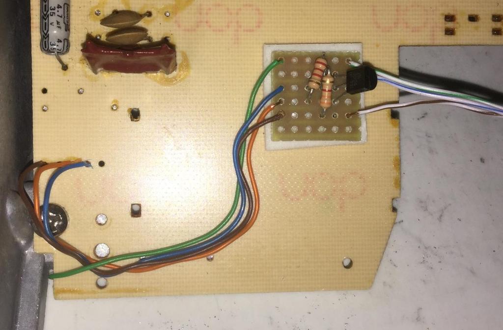
4 In the middle of the board on the right hand side is a transistor (Q202). you need to remove the transistor by cutting all 3 leads with the wire cutters or de-soldering it. When done it should look like this. Now take the switchboard. You need to cut the 5 pins going into the RF modulator circuit board (silver box with circuit board attached to side. You can break off the small circuit board attached to the RF modulator and throw it out, but if you want you can bend the pins up out of the way and leave the small circuit board attached. Remove the 5 pins using your de-soldering tool so that the holes are open as in the picture below. You can also remove the big red component L201, as that is supposed to make the picture better, but it can be left on the board also. The group of 4 wires are the input wires that go to the main board. Strip about 1/2 off of both ends of the input wires and attach them to the mod kit. Brown is the GND, Orange is +5v, Blue is Video, and Green is Audio.

5 The group of 3 wires are out wires that attach to the RCA jacks. The output wires should be stripped to different lengths as in the picture. About 1/2 for Blue/White, 1 for Green/White, and 2 for Brown/White. On the output side of the mod kit, Brown/White is for GND, Green/White for Audio, and Blue/White for Video. Attach the Brown, Orange, and Blue input wires to the switchboard like in the picture and solder them in from underneath. Make sure the Brown wire goes into pin 1 where the RF modulator pins were. The Orange goes into pin 3, and the Blue into pin 4. Take the main board and turn it over. The Green wire needs to be attached from underneath because of the metal casing. Attach it to the hole indicated on the left side of the board as in the picture. There is no component in this hole but you might need to remove the solder first with your de-soldering tool. This is an open hole connected to C210 if you look at the board from the top. You may want to drill a hole in the side of the metal casing to facilitate the yellow wire s path from underneath the circuit board to the outside of the case. Or, more sympathetically, file a groove near the screw hole to allow the wires to pass under the casing without being nipped when it s reassembled. See the image below that shows where to use a flat file on its edge to cut the groove.
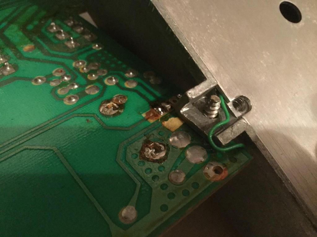
6


7 Now you need to remove a resistor (R213) along the bottom of the main board, if there is one. You can just cut it off at both ends. Now the main board and switchboard are done. Take the bottom half of the case and put a piece of masking tape where you want the RCA jacks to go. Use a ruler and marker and make 3 dots on the tape 1/2 apart. Then drill 1/8 pilot holes on the dots, and use the 1/4 drill bits on the holes to make them ready for the RCA jacks. The tape and marker are just extra precautions; you could also just drill the holes if you want. Attach the RCA jacks by mounting them into the case with the ground ring and nut on the inside. Make sure they are tight. Have the ground ring holes be at or near the top and bend them down to make soldering easier. Take the Black output wire with the longest amount of bare wire and solder it to all three ground rings like in the picture below. Take the Red wire and solder it to the Red and White jacks. Take the Blue wire and solder it to the yellow jack.


8 Now you are ready to put everything back together. First you need to adjust the color potentiometer on the bottom left of the main board. It is the big plastic circle and is the only pot on the board. Attach the power, ribbon, and RCA cables and use a game you are familiar with to adjust it so the colors are just right. A game like Frogger or Pitfall with a variety of bright colors is ideal. Here is Missile Command s initial screen colours, which is what I use to colour adjust: Now unplug everything, and put the top metal casing over the main board and secure it with the two screws. Then screw in the switch board to the main board and put them both in the case. Be sure to put the dust cover back on the plugs and


9 joystick ports and the foam covers on all the switches. Then peel the bottom off of the double sided tape and stick it to the bottom case on the right hand side. Now put the top cover back on, and put back the 8 screws back in. Start with the two in the middle. After that you are done and ready to enjoy your Atari with composite video! Please leave a comment below and let me know how you made out!


10 PAL Console The 6 switch should be exactly the same. Just follow the NTSC guide to take it apart. Below are pictures of where you pick up the audio. The board layout is different but the components are numbered the same. The hole next to C210 is where you get the audio from. Remove Q202, and the pins going into the RF modulator are exactly the same so follow the NTSC guide for everything else. Removing R213 also helps improve the picture for some people too so remove that as well if you have it. L201 (the tall red component) can be removed also if you want. Also, you will find that the modulator may look totally different: The best way to tackle this type of modulator is to de-solder all the four posts that hold the unit to the board (red circled points in above photo). The two pins on the left (yellow circle) can then be de-soldered and the unit removed. The mod board can then be installed following the original NTSC instructions:
11

")

12 Installation Guide 4 Switch Atari Switch Video Mod Installation Guide Disclaimer: I am not responsible for any damage done to your Atari. This mod is designed to remove the RF output. The mod will work if performed correctly to a fully functioning Atari. Perform at your own risk. Tools You Will Need Philips Screwdriver Soldering Iron and Solder De-soldering Tool (De-soldering Iron, Bubble, Vacuum, Braid) Wire Cutters/Strippers Needle Nose Pliers Drill with 1/4 and 1/8 bits NTSC Console Turn the Atari over and remove the 4 screws. Set them aside for later. Remove the main board out of the console by disconnecting the RF cable shown below. Take off the black foam covers on the switches and set them aside for later. Take the foil tape off the switches and throw it away.


13 Using the need nose pliers, bend up the 4 tabs around the metal case. Remove the metal casing (top and bottom) and throw it away. You should now have the main board like this ready to modify. In the middle of the board is a transistor you will have to remove. It is labeled Q201 on some 4 switch versions and Q202 on others. It s shown in the picture on the left. Simply cut all 3 leads of the transistor and throw it out. Make sure none of the leads coming out of the board are touching each other. Remove R209 resistor.then you need to remove the 4 pins to the RF modulator (metal box with small circuit board attached). Simply cut the pins and bend them up so they are out of the way, or you could break off the small circuit board entirely because it is no longer used. You can also remove the big red component L201, as that is supposed to make the picture better, but it can be left on the board also. The group of 4 wires are the input wires that go to the main board. Strip about 1/2 off of both ends of the input wires and attach them to the mod kit. Brown is the GND, Orange is +5v, Blue is Video, and Green is Audio.

.")
14 The group of 3 wires are out wires that attach to the RCA jacks. The output wires should be stripped to different lengths as in the picture. About 1/2 for Blue/White, 1 for Green/White, and 2 for Brown/White. On the output side of the mod kit, Brown/White is for GND, Green/White for Audio, and Blue/White for Video. First you need to use your de-soldering tool and clean out the holes where the RF modulator pins were. Then connect the input wires and solder them in from underneath as shown in the picture. Make sure the brown wire goes to pin #1, orange to pin #3, and blue to pin #4. Then attach the green wire to the base of the resistor as shown (R206). You could also use the open hole on the capacitor immediately to the right (C208), as they are connected to each other. Now the main board is done. Take the bottom half of the case and put a piece of masking tape where you want the RCA jacks to go. Use a ruler and marker and make 3 dots on the tape 1/2 apart. Then drill 1/8 pilot holes on the dots, and use the 1/4 drill bits on the holes to make them ready for the RCA jacks. The tape and marker are just extra precautions, you could also just drill the holes if you want.


15 Attach the RCA jacks by mounting them into the case with the ground ring and nut on the inside. Make sure they are tight. Have the ground ring holes be at or near he top and bend them down to make soldering easier. Take the Black output wire with the longest amount of bare wire and solder it to all three ground rings like in the picture below. Take the Red wire and solder it to the Red and White jacks. Take the Blue wire and solder it to the yellow jack. Now you are ready to put the mainboard into the case. First you need to adjust the color pot on the bottom left of the mainboard. Attach the RCA and power cables and use a game with nice bright colors you are familiar with like Pitfall or Frogger. Adjust the pot so the colors are just right. Then peel off the bottom of the double-sided tape and stick it to the right side of the bottom case. Replace the foam dust covers, top case, and the screws and you are ready to play your Atari with composite video! Please leave a comment below and let me know how it works!


16 PAL Console Same thing here, just follow the NTSC instructions to remove the transistor. Again, it might be labeled Q201 or Q202 depending on your version. Audio is taken from bottom of R208 or C206 and pins 1,3,4 are the same. The picture on the right says to take out R22 and R209/C209. This person said it improved the brightness and picture quality so give it a try if you like.


17 Installation Guide 7800 Atari 7800 Video Mod Installation Guide Disclaimer: I am not responsible for any damage done to your Atari. This mod is designed to permanently remove the RF output. The mod will work if performed correctly to a fully functioning Atari. Perform at your own risk. Tools You Will Need Philips Screwdriver Soldering Iron and Solder De-soldering Tool (De-soldering Iron, Bubble, Vacuum, Braid) Wire Cutters/Strippers Needle Nose Pliers Drill with 1/4 and 1/8 bits NTSC Console Turn the Atari over and remove the 5 screws. Set them aside for later. Remove the main board out of the console. Using the need nose pliers, twist the tabs around the metal case so they are straight. Remove the metal casing (top and bottom) and throw it away.
.")

18 You should now have the main board like this ready to modify. On the top left hand side of the board are two resistors (R3, R5) you have to remove. They are marked in the picture. Use the wire cutters to cut both ends and throw them away. Then you need to cut the 4 pins going into the RF modulator circuit board (silver box with circuit board attached to side). Then break off the small circuit board attached to the RF modulator and throw it out. The picture should look like below. Remove the 4 pins using your de-soldering tool so that the holes are open. Then remove the solder from the other hole marked on the board. These are where the input wires will connect to the mainboard. The system should look like the picture on the right. The group of 4 wires are the input wires that go to the main board. Strip about 1/2 off of both ends of the input wires and attach them to the mod kit. Brown is the GND, Orange is +5v, Blue is Video, and Green is Audio. The group of 3 wires are out wires that attach to the RCA jacks. The output wires should be stripped to different lengths as in the picture. About 1/2 for Blue/White, 1 for Green/White, and 2 for Brown/White. On the output side of the mod kit, Brown/White is for GND, Green/White for Audio, and Blue/White for Video.


19 Attach the input wires to the main board like in the picture and solder them in from underneath. Make sure the brown wire goes into pin 1 where the RF modulator pins were. The orange goes into pin 2, and the Blue into pin 3. The green wire should be soldered to the lower hole underneath the two IC s. An alternate location for the green wire is the left side of the capacitor (Green component, 2nd from bottom in row of resistors). After this the main board is done. (Unless you want to do the optional next step for the POKEY Audio. There are only a couple games that use the pokey audio so this step isn t necessary unless you have commando, ball blazer, or some custom made game. If not, then just skip to the next step. If you want to install it, then you will need to remove the C10 capacitor which is located just below the channel select switch. In the picture I removed the switch since it isn t needed anymore and is slightly in the way. Use whatever de-solder tool you have to clear out the top hole and solder the green wire you set aside earlier in the top of C10. All you need to do is combine the audio signals with the green/white output wire. The best thing to do is leave the wire connected to the top of C10 until the very last step. After you have completed the mod and are ready to put the cover on, solder the wire to the center post of either the Red or White RCA jack. That will combine the audio signals so you have the pokey for games that use it. (Note: Some people have had an issue with the balance of volume on the main audio and the pokey, if the pokey is too soft add a 6.8k resistor (or any resistor near that value) in series to the main audio out wire. This should balance out the audio better.)


20 Take the bottom half of the case and put a piece of masking tape on the left hand side where you want the RCA jacks to go. Some cases can be very brittle so be careful. Use a ruler and marker and make 3 dots on the tape 1/2 apart. Then drill 1/8 pilot holes on the dots, and use the 1/4 drill bits on the holes to make them ready for the RCA jacks. The tape and marker are just extra precautions, you could also just drill the holes if you want. Attach the RCA jacks by mounting them into the case with the ground ring and nut on the inside. Make sure they are tight. Have the ground ring holes be at or near the top and bend them down to make soldering easier. Take the brown/white output wire with the longest amount of bare wire and solder it to all three ground rings like in the picture below. Take the green/white wire and solder it to the Red and White jacks. Take the Blue/white wire and solder it to the yellow jack.


21 Now you are ready to put the main board into the case. Peel off the bottom of the double sided tape and stick it to the left inside edge of the bottom case. Replace the top case and screws and you are ready to play your Atari with composite video! Leave a comment below and let me know how you made out!
.")

22 PAL Console Remove the 3 resistors circled R62, R32, R33. The green wire should go to the right side of the R32 hole, that is the audio spot. If you want pokey sound you need to add your own wire and connect it to the right side of R33 (You can skip the audio section of the NTSC guide). Note you don t have to snap off the piece of board that comes out of the modulator. You can simply cut the wires and solder the mod board wires to them. There is enough space behind the board (marked in the above picture) if you wish to place the mod board there as well as retain the metal cover.


23 Then the blue, orange, and brown input wires go to the same exact spot that is on the guide. The NTSC and PAL instructions are identical for everything else. Cut the 4 pins and remove the small board coming out of the RF modulator, that is where the remaining input wires go. Then just put in the RCA jacks and connect the 3 output wires to them like in the guide. I d recommend the first phono socket hole to be placed as shown it can go lower if needed, but will be tricky to wire up the phono socket.
UAV Ultimate Atari Video A7800
 UAV Ultimate Atari Video A7800 Basic Install guide because this is really easy mod to do! The UAV is a wonderful piece of tech for what it can do. To summarize, the UAV is a replacement video encoder and
Bas Gialopsos Atari PureVideo Encoder Module 2600VECr5.2
 Bas Gialopsos 2014 Atari PureVideo Encoder Module 2600VECr5.2 Table of Contents Description Disclaimer Technical and Signal Identification Installation Instructions Tools Required Caution Installation
MUK REAR PANEL ASSEMBLY ASSEMBLY INSTRUCTIONS
 Rev B. 13 August 2017 ASSEMBLY INSTRUCTIONS The Midnight Ultimate Keyer (MUK) consists of two functional assemblies: Rear Panel containing the interface and power connectors. Front Panel containing the
Mal-2 assembly guide v1.0
 Mal-2 assembly guide v.0 SONIC POTIONS Schematic and BOM The BOM can be found on Google Docs Prepare the PCB Separate the PCBs using some pliers. PCB We start with the lower PCB and assemble it beginning
Building a MidiBox LCD Cable
 Building a MidiBox LCD Cable By Jim Henry, 3-Apr-2004 An LCD panel may be connected to the Core module by a 16 conductor flat ribbon cable. A 16 pin insulation displacement connector (IDC) terminates one
DIY Guide - Building Franky v1.1, the SEGA Audio and Videocard for MSX
 DIY Guide - Building Franky v1.1, the SEGA Audio and Videocard for MSX 2015 FRS & MSXpró. Translation by FRS and Supersoniqs. Table of Contents Introduction... 3 Materials needed... 3 Audio volume boost...
Fixed Audio Output for the K2 Don Wilhelm (W3FPR) & Tom Hammond (NØSS) v August 2009
 & Tom Hammond (NØSS) v August 2009") Fixed Audio Output for the K2 Don Wilhelm (W3FPR) & Tom Hammond (NØSS) v. 2.1 06 August 2009 I have had several requests to provide a fixed audio output from the K2. After looking at the circuits that
Fixed Audio Output for the K2 Don Wilhelm (W3FPR) & Tom Hammond (NØSS) v. 2.1 06 August 2009 I have had several requests to provide a fixed audio output from the K2. After looking at the circuits that
NewScope-7A Operating Manual
 2016 SIMMCONN Labs, LLC All rights reserved NewScope-7A Operating Manual Preliminary May 13, 2017 NewScope-7A Operating Manual 1 Introduction... 3 1.1 Kit compatibility... 3 2 Initial Inspection... 3 3
Documentation VFD clock 8 a clock
 Documentation VFD clock 8 a clock This documentation is protected by our copyright. It must not be used for commercial purposes. Congratulations on your purchase of your VFD clock. To guarantee success
imac Intel 27" EMC 2546 isight Camera and Microphone Cable Replacement
 imac Intel 27" EMC 2546 isight Camera and Microphone Cable Replacement Replace the isight/microphone cable in your Late 2012 27" imac. Written By: Andrew Optimus Goldberg ifixit CC BY-NC-SA www.ifixit.com
TKEY-K16. Touch CW automatic electronic keyer. (No moving parts no contacts) Assembly manual. Last review: March 15, 2018
 Assembly manual. Last review: March 15, 2018") TKEY-K16 Touch CW automatic electronic keyer (No moving parts no contacts) Assembly manual Last review: March 15, 2018 Commands and use manual of the K16 and Updates and news: www.ea3gcy.com Thanks for
TKEY-K16 Touch CW automatic electronic keyer (No moving parts no contacts) Assembly manual Last review: March 15, 2018 Commands and use manual of the K16 and Updates and news: www.ea3gcy.com Thanks for
Galilean Moons. dual amplitude transmutator. DIY ASSEMBLY MANUAL v1.02
 Galilean Moons dual amplitude transmutator DIY ASSEMBLY MANUAL v1.02 Contents Contents... 2 Introduction... 3 Eurorack Kit Assembly... 4 Resistors... 4 IC Sockets... 5 Ceramic/Film Capacitors... 5 Transistors
Main PCB (The small one)
") Thanks for choosing our kits! This manual is written taking with the problems that we usually find in our workshops in mind. Also the order is meant to make assembly as easy as possible. Some steps are
Thanks for choosing our kits! This manual is written taking with the problems that we usually find in our workshops in mind. Also the order is meant to make assembly as easy as possible. Some steps are
While the parts are already inventoried at the factory, please verify the inventory check as you go:
 Thank you for purchasing the kit for building the WJ9J DTMF controller. After building, you should read the document on operation (WJ9JDTMFControllerV5.pdf) in order to use. This is also in the link in
DL-1A. RF dummy load - 50Ω 20W. Assembly manual. Last update: May 1, Thank you for constructing the DL-1A dummy load kit
 DL-1A RF dummy load - 50Ω 20W Assembly manual Last update: May 1, 2016 ea3gcy@gmail.com Updates and news at: www.qsl.net/ea3gcy Thank you for constructing the DL-1A dummy load kit Have fun assembling it
Multi-Key v2.4 Multi-Function Amplifier Keying Interface
 Multi-Key v2.4 Multi-Function Amplifier Keying Interface ASSEMBLY & OPERATION INSTRUCTIONS INTRODUCTION The Harbach Electronics, LLC Multi-Key is a multi-function external device designed for the safe
Introduction 1. Green status LED, controlled by output signal ST. Sounder, controlled by output signal Q6. Push switch on input D6
 Introduction 1 Welcome to the GENIE microcontroller system! The activity kit allows you to experiment with a wide variety of inputs and outputs... so why not try reading sensors, controlling lights or
Introduction 1. Green status LED, controlled by output signal ST
 Introduction 1 Welcome to the magical world of GENIE! The project board is ideal when you want to add intelligence to other design or electronics projects. Simply wire up your inputs and outputs and away
Introduction 1. Digital inputs D6 and D7. Battery connects here (red wire to +V, black wire to 0V )
") Introduction 1 Welcome to the magical world of GENIE! The project board is ideal when you want to add intelligence to other design or electronics projects. Simply wire up your inputs and outputs and away
Introduction 1 Welcome to the magical world of GENIE! The project board is ideal when you want to add intelligence to other design or electronics projects. Simply wire up your inputs and outputs and away
Bill of Materials: Super Simple Water Level Control PART NO
 Super Simple Water Level Control PART NO. 2169109 Design a simple water controller in which electrodes are required to sense high and low water levels in a tank. Whenever the water level falls below the
Wasabi 360 Ultra Installation Guide v1.2
 Wasabi 360 Ultra Installation Guide v1.2 For HW version 1.0 Introduction To install your Wasabi X360 Ultra you will have to disassemble your Xbox Phat. We recommend you follow one of the many Xbox Phat
Tube Cricket Build Guide
 Tube Cricket Build Guide The Tube Cricket is a small-wattage amp that puts out about 1 watt of audio power. With a 12AU7 tube-preamp and a JRC386 power amp, the Tube Cricket gives you great tone in a compact
imac Intel 27" EMC 2639 Display Replacement
 imac Intel 27" EMC 2639 Display Replacement Replace the Display in your imac Intel 27" EMC 2639. Rédigé par: Walter Galan ifixit CC BY-NC-SA fr.ifixit.com Page 1 de 16 INTRODUCTION Removing the display
Atari 400/800 Super Color CPU Card
 Installation Instructions Atari 400/800 Super Color CPU Card Date: 2017, May 3 rd, version 1.1 Author: Jürgen van Radecke (tfhh) Introduction Hi, Thank you for your purchase of a Super Colour CPU Card!
TECHNOLOGY WILL SAVE US: THE LUMIPHONE
 TECHNOLOGY WILL SAVE US: THE LUMIPHONE This is a step-by-step guide to soldering your own Lumiphone. The equipment you should have at your station: goggles, soldering mat, soldering Iron, solder and side
Industrial Monitor Update Kit
 Industrial Monitor Update Kit (Bulletin Number 6157) Installation Instructions 2 Table of Contents Table of Contents Industrial Monitor Update Kit... 3 Overview... 3 Part 1 - Initial Preparation... 5 Part
PR-101 STEREO PREAMPLIFIER Phono Preamp ASSEMBLY MANUAL
 PR-101 STEREO PREAMPLIFIER Phono Preamp ASSEMBLY MANUAL 2016 AkitikA LLC All rights reserved Revision 1p18 March 12, 2016 Page 1 of 24 Table of Contents Table of Contents... 2 Table of Figures... 2 Section
Mitsubishi WD57734 DLP Chip Replacement
 Mitsubishi WD57734 DLP Chip Replacement Replace the DLP chip in your Mitsubishi WD57734. Written By: David Sylvester ifixit CC BY-NC-SA www.ifixit.com Page 1 of 10 INTRODUCTION This guide will detail the
Sega MegaDrive 1 RGB Bypass Installation Guide Rev 1.1
 Sega MegaDrive 1 RGB Bypass Installation Guide Rev 1.1 This step by step guide describes the Installation of the open source Voultar RGB Bypass Amplifier board for the original SEGA MegaDrive/Genesis 1.
Snail Fence InteleCell Deployment Guide
 Snail Fence InteleCell Deployment Guide Preparation 1. Prepare deployment trip by making sure you have the following materials and tools when you fly up to the site: InteleCell NEMA Enclsoure (grey plastic
Bill of Materials: Magic Color PART NO
 Magic Color PART NO. 2193838 Magic color is a guessing game. With this game you can surprise your friends and leave them with amazement, how the game guesses what they have in their minds. Only two selections
E4200 Antenna Installation Instructions: 1. Soldering required (here is the list of tools you will need)
") Thank you for purchasing the 6 Antenna Mod Kit for your Linksys router. First we will show you how to install the antennas for your router. Next we will teach you how to setup the DD-WRT firmware which
Thank you for purchasing the 6 Antenna Mod Kit for your Linksys router. First we will show you how to install the antennas for your router. Next we will teach you how to setup the DD-WRT firmware which
3. Electronics and MMU2 unit assembly
 Written By: Jakub Dolezal 2018 manual.prusa3d.com/ Page 1 of 34 Step 1 Tools necessary for this chapter Please prepare tools for this chapter: 2.5mm Allen key for M3 screws 2mm Allen key for nut alignment
Parts Checklist - Please note there is no resistor R3. Diodes, LED and transistors are polarized see construction stages
 Xtal Check Kit build Read me first! -------- UPDATED GUIDE------ September 12, 2018--------- The following steps are designed to get your Xtal check kit built and operational. This is a good beginner s
Tips to disassemble your TF300. Will hopefully help you not make a couple of the mistakes I did. Written By: B0NK3R5
 Disassembling Asus Transformer Pad TF300 Tips to disassemble your TF300. Will hopefully help you not make a couple of the mistakes I did. Written By: B0NK3R5 ifixit CC BY-NC-SA www.ifixit.com Page 1 of
R/C Afterburner Light Kit For Electric EDF Jets 2009 Hyperdyne Labs
 R/C Afterburner Light Kit For Electric EDF Jets 2009 Hyperdyne Labs http://www.hyperdynelabs.com Congratulations on purchasing the Afterburner light kit. Your kit is hand assembled in the USA, and we appreciate
Build your own: Track Display
 Build your own: Track Display! " #! $% $ & ' $ ' ( ) * +, Track Display Manual 0706 web distribution version Table of Contents Section 1 Page 2 Quick Start Guide -Connecting 2 LEDs to Output #1 -Operating
Total solder points: 123 Difficulty level: beginner 1. advanced AUDIO ANALYZER K8098. audio gea Give your. . high-tech ILLUSTRATED ASSEMBLY MANUAL
 Total solder points: 123 Difficulty level: beginner 1 2 3 4 5 advanced AUDIO ANALYZER K8098 ra audio gea Give your. look high-tech ILLUSTRATED ASSEMBLY MANUAL H8098IP-1 Features & Specifications Features
RSL MusicPower Plug-In Installation Manual For Naim NAC 72 Preamp
 RSL MusicPower Plug-In Installation Manual For Naim NAC 72 Preamp (Updated to reflect the adjustable gain output boards Z200V) www.ryansoundlab.com RSL MusicPower Plug-In Installation Manual for Naim NAC
Etherwave Plus Field Upgrade Instructions
 Etherwave Plus Field Upgrade Instructions The Etherwave Plus Field Upgrade is an advanced project for upgrading a standard Moog Music Etherwave theremin to the Etherwave Plus. The new features of the Etherwave
Nixie Clock Type Frank 2 Z570M
 Assembly Instructions And User Guide Nixie Clock Type Frank 2 Z570M Software version: 7R PCB Revision: 11 April 09-1 - 1. INTRODUCTION 1.1 About the clock Nixie clock type Frank 2 is a compact design with
Technical Information Bulletin
 June 4, 2001 #TIB0003 Units Affected: Model Serial Numbers Model Serial Numbers SVT-2PRO T2PDxxxxxxxxx SVTAV AXVDxxxxxxxxx ATLDxxxxxxxxx BJIDMAxxxxxxx SVT-2PROJ T2PJxxxxxxxxx SVTAVJ BAHJxxxxxxxxx ATLJxxxxxxxxx
FIST-MB2-S. FIST Medium Box for Cable Splicing Only. 4 Cable installation. 1 Introduction. Contents. 2 General. 5. Fiber routing to individual trays
 FIST-MB2-S I N S T A L L A T I O N I N S T R U C T I O N FIST Medium Box for Cable Splicing Only Contents 1 Introduction 1.1 Product description 2 General 2.1 Tools 2.2 Kit contents 3 Installation and
Commissioning Guide. firepickdelta. Commissioning Guide. Written By: Neil Jansen firepickdelta.dozuki.com Page 1 of 22
 firepickdelta Commissioning Guide Written By: Neil Jansen 2017 firepickdelta.dozuki.com Page 1 of 22 Step 1 Pre-Requisites Before commissioning, please make sure ALL of the following steps have been completed,
Obtained from Omarshauntedtrail.com
 http://www.cindybob.com/halloween/ledlighting/ledspotlights/ Introduction In our 2005 haunt providing 120V AC power to the various lights and props requiring it became a fairly large problem. Extension
PowerBook G4 Aluminum 12" GHz LCD panel upgrade
 PowerBook G4 Aluminum 12" 1-1.5 GHz LCD panel upgrade Upgrade a 1400x1050 LCD panel. Written By: martin ifixit CC BY-NC-SA www.ifixit.com Page 1 of 18 INTRODUCTION The original LCD 1024x768 resolution
Tip: Faller Mittelstadt Apartments with Controlled LED Lighting Date: , Addition
 Hi All, I have had the 130926 Mittelstadt apartments shown below on my layout for a long time and thought it was about time to add LED lighting to the buildings. With my success at upgrading the Faller
Elecraft KXAT2 Automatic Antenna Tuner Installation Instructions
 Elecraft KXAT2 Automatic Antenna Tuner Installation Instructions Revision A, May 23, 2016 E740294 Copyright 2016, Elecraft, Inc. All Rights Reserved Introduction The KXAT2 internal automatic antenna tuner
VU-1 VU Meter Kit Volume Unit Meter
 VU-1 VU Meter Kit Volume Unit Meter Simplicity Counts, Detail Matters. No part of this document may be reproduced, either mechanically or electronically, posted online on the Internet, in whole or in part,
MACH3 LaserAce Installation Manual Revision 1. MACH3 LaserAce Installation Manual
 WWW.LASERARCADE.COM MACH3 LaserAce Installation Manual Revision 1 MACH3 LaserAce Installation Manual Table of Contents Introduction...1 Parts supplied with MACH3 FNI...1 Why the MACH3 FNI is required...2
apple Service Source Apple Studio Display 17" LCD (ADC) Updated 6 Decenber Apple Computer, Inc. All rights reserved.
 Updated 6 Decenber Apple Computer, Inc. All rights reserved.") apple Service Source Apple Studio Display 17" LCD (ADC) Updated 6 Decenber 2004 2003 Apple Computer, Inc. All rights reserved. apple Service Source Take Apart Apple Studio Display 17" LCD (ADC) 2003 Apple
apple Service Source Apple Studio Display 17" LCD (ADC) Updated 6 Decenber 2004 2003 Apple Computer, Inc. All rights reserved. apple Service Source Take Apart Apple Studio Display 17" LCD (ADC) 2003 Apple
imac Intel 21.5" EMC 2544 Camera and Microphone Cable Replacement
 imac Intel 21.5" EMC 2544 Camera and Microphone Cable Replacement Replace the isight/microphone cable in your imac Intel 21.5" EMC 2544. Geschreven door: Sam Lionheart ifixit CC BY-NC-SA nl.ifixit.com
AT-AUTO (tm) QRO Keyline Upgrade Kit Installation Manual
 QRO Keyline Upgrade Kit Installation Manual") AT-AUTO (tm) QRO Keyline Upgrade Kit Installation Manual P.O. Box 341543 Beavercreek, Ohio 45434 5 September, 2015 Copyright 2015 ii Contents 1 Introduction 2 1.1 General Description and Purpose........................
AT-AUTO (tm) QRO Keyline Upgrade Kit Installation Manual P.O. Box 341543 Beavercreek, Ohio 45434 5 September, 2015 Copyright 2015 ii Contents 1 Introduction 2 1.1 General Description and Purpose........................
imac Intel 20" EMC 2133 and 2210 LCD Backlights (CCFL) Replacement
 Replacement") imac Intel 20" EMC 2133 and 2210 LCD Backlights (CCFL) Replacement The CCFL back lights are replaceable. I have pulled mine apart and documented my method. '''NOTE''' This is not for the feint hearted!
imac Intel 20" EMC 2133 and 2210 LCD Backlights (CCFL) Replacement The CCFL back lights are replaceable. I have pulled mine apart and documented my method. '''NOTE''' This is not for the feint hearted!
Samsung HL56A650C1FXZA 56-inch DLP TV DLP Chip Replacement
 Samsung HL56A650C1FXZA 56-inch DLP TV DLP Chip Replacement A common failure item for Samsung DLP televisions is the DLP chip. Mirrors within the chip stick in one position or another, leading to white
IPad 4 REPAIR GUIDE. Version Edition
 IPad 4 REPAIR GUIDE Version 1 2016 Edition IPad 4 REPAIR GUIDE LCD AND DIGITIZER REPLACEMENT RiAna Soto Repair Training Specialist rsoto@cellairis.com FOR EVERY REPAIR MAKE SURE TO COMPLETE, INITIAL, AND
Medium Box for Cable Termination
 FIST-MB2-T I N S T A L L A T I O N I N S T R U C T I O N Medium Box for Cable Termination Contents 1 Introduction 1.1 Product description. 2 General 2.1 Tools 2.2 Kit contents 3 Installation and pre assembling
[ Photos ] [ Wares ] [ Library ] [ Dave's Web ] [ Matt's Web ] Wares [ SWISH ] [ Simple Search ] [ Trunk Calc ]
![[ Photos ] [ Wares ] [ Library ] [ Dave's Web ] [ Matt's Web ] Wares [ SWISH ] [ Simple Search ] [ Trunk Calc ]](/thumbs/85/91698811.jpg "[ Photos ] [ Wares ] [ Library ] [ Dave's Web ] [ Matt's Web ] Wares [ SWISH ] [ Simple Search ] [ Trunk Calc ]") [ Photos ] [ Wares ] [ Library ] [ Dave's Web ] [ Matt's Web ] Wares [ SWISH ] [ Simple Search ] [ Trunk Calc ] Realistic PRO-2006 Hardware Modifications Note Edited on January 1st, 1970, 00:00 UT. Improper
[ Photos ] [ Wares ] [ Library ] [ Dave's Web ] [ Matt's Web ] Wares [ SWISH ] [ Simple Search ] [ Trunk Calc ] Realistic PRO-2006 Hardware Modifications Note Edited on January 1st, 1970, 00:00 UT. Improper
Christmas LED Snowflake Project
 Christmas LED Snowflake Project Version 1.1 (01/12/2008) The snowflake is a follow-on from my Christmas star project from a few years ago. This year I decided to make a display using only white LEDs, shaped
IPad 3 (glass) REPAIR GUIDE. Version Edition
 REPAIR GUIDE. Version Edition") IPad 3 (glass) REPAIR GUIDE Version 1 2016 Edition IPad 4 REPAIR GUIDE LCD AND DIGITIZER REPLACEMENT RiAna Soto Repair Training Specialist rsoto@cellairis.com FOR EVERY REPAIR MAKE SURE TO COMPLETE, INITIAL,
IPad 3 (glass) REPAIR GUIDE Version 1 2016 Edition IPad 4 REPAIR GUIDE LCD AND DIGITIZER REPLACEMENT RiAna Soto Repair Training Specialist rsoto@cellairis.com FOR EVERY REPAIR MAKE SURE TO COMPLETE, INITIAL,
RF Nomad Semi-SMT. SDIY Kit Assembly Manual
 RF Nomad Semi-SMT Introduction Thanks for purchasing the RF Nomad SDIY kit from Evaton Technologies! The RF Nomad SDIY kit is a voltage-controlled shortwave radio receiver in Eurorack format. The RF Nomad
MAKE AN RGB CONTROL KNOB.
 MAKE AN RGB CONTROL KNOB. This is a knob based colour changing controller that uses a custom programmed microcontroller to pack a lot of features into a small affordable kit. The module can drive up to
MAIN PCB (The small one) OPEN MAIN BOARD BAG A
 OPEN MAIN BOARD BAG A") THANKS FOR CHOOSING ONE OF OUR KITS! This manual has been written taking into account the common issues that we often find people experience in our workshops. The order in which the components are placed
THANKS FOR CHOOSING ONE OF OUR KITS! This manual has been written taking into account the common issues that we often find people experience in our workshops. The order in which the components are placed
A Huf Puf VFO stabilizer for the YAESU FT-707
 A Huf Puf VFO stabilizer for the YAESU FT-707 Bruno Beckers ON6AB Page 1 The Yaesu FT707 is a good object to add a Huff Puff VFO stabilizer developed by the late Klaas Spaargaren PA0KSB. The version of
Dust Sensor using GP Y
 Dust Sensor using GP Y Dust sensors detect fine dust ( aerosol ) floating in the air. They are used to determine air quality indoor and outdoor. Limits of the GP2Y10 The GP2Y10 sensor was developed to
Scale Track System. 21 Century y Signal System 2-Rail Manual
 Scale Track System st 21 Century y Signal System 2-Rail Manual TABLE OF CONTENTS Introduction...2-3 Road Signal Board Diagram and Definitions...4-6 Tips for Handling the Circuit Board...6 2-Rail Detector
How To Build Megavolt s Small Buffered JTAG v1.2
 How To Build Megavolt s Small Buffered JTAG v1.2 Abstract A JTAG cable should be considered mandatory equipment for any serious tester. It provides a means to backup the information in the receiver and
COLOUR CHANGING USB LAMP KIT
 TEACHING RESOURCES SCHEMES OF WORK DEVELOPING A SPECIFICATION COMPONENT FACTSHEETS HOW TO SOLDER GUIDE SEE AMAZING LIGHTING EFFECTS WITH THIS COLOUR CHANGING USB LAMP KIT Version 2.1 Index of Sheets TEACHING
Azatrax Model Railroad Track Signal Control - Single Track
 Installation Guide Azatrax Model Railroad Track Signal Control - Single Track TS2 What it is: The TS2 operates one or two trackside block signals (one in each direction) on one track to simulate the block
DEM 9ULNACK 3.4 GHz. PHEMT LNA amplifier complete kit assembly guide
 DEM 9ULNACK 3.4 GHz. PHEMT LNA amplifier complete kit assembly guide SPECIFICATIONS Noise Figure: < 0.8 db Gain: > 15 db Frequency Range: 3400-3500 MHz Input Voltage: 7-16 VDC Description: The 9ULNACK
LP-PAN Preamp Kit Assembly Manual
 LP-PAN Preamp Kit Assembly Manual December 2010 TelePost Incorporated Rev. A9 1 Table of Contents Introduction... 2 Specifications... 3 Parts List... 4 Assembly... 5 Checkout / Schematic... 9 Introduction
G4HUP Panoramic Adaptor Installation TS2000
 G4HUP Panoramic Adaptor Installation TS2000 These instruction cover installation of the PAT board in the 2 nd IF of the TS2k 10.695MHz this gives access to all receiver options on the main receiver, including
Hi-Rez Projections Inc. 20 Main St. Ashland, MA MP8 CRT Installation
 Hi-Rez Projections Inc. 20 Main St. Ashland, MA 01721 508-881-1613 www.hometheater1.com MP8 CRT Installation Table of Contents Overview...1 Precautions...1 Components...1 CAUTIONS Before Beginning...2
Mitsubishi WS-55859: Changing out your capacitors when your set will not Turn On, the "Green Light is Flashing" and it won't give you an Error Code.
 Mitsubishi WS-55859: Changing out your capacitors when your set will not Turn On, the "Green Light is Flashing" and it won't give you an Error Code. Taken From http://hdtvoice.com/voice/showthread.php?t=32186
Replacing the PanelMate epro PS, PanelMate epro PS Classic, PanelMate epro PS EE, and PanelMate epro PS OD 7685x-15xx Series Backlight Assembly
 Introduction Replacing the PanelMate epro PS, PanelMate epro PS Classic, PanelMate epro PS EE, and PanelMate epro PS OD 7685x-15xx Series Assembly Instruction Leaflet IL04802009E Effective September 2008
Installing iphone 3G Display
 Tools used in this guide Phillips #00 Screwdriver (1) Small suction cup (1) Spudger (1) Parts relevant to this guide iphone 3G Display (1) Cracked or faulty display? Replacing the glass is somewhat involved
Installing The PK-AM keyer and. from Jackson Harbor Press Operating: A Morse code keyer chip with pot speed control
 Installing The PK-AM keyer and from Jackson Harbor Press Operating: A Morse code keyer chip with pot speed control The PK-AM keyer is a modification for the PK-AM kit, it changes the AM transmitter to
NOTE: We take no responsibility if anything goes wrong or breaks when you try to do this!
 How to install a reset switch in the xbox game controller Tutorial written by: Xboxmod08 Team Of Sweden Version 1.2.1 (Corrected a few things from the SCART section) Version: 1.2 (Replaced some pictures
SCdefault. 900 Installation instructions. Accessories Part No. Group Date Instruction Part No. Replaces :36-29 Sep
 SCdefault 900 Installation instructions SITdefault Upgrade to Premium 300 sound system MONTERINGSANVISNING INSTALLATION INSTRUCTIONS MONTAGEANLEITUNG INSTRUCTIONS DE MONTAGE Accessories Part No. Group
MONO AMPLIFIER KIT ESSENTIAL INFORMATION. Version 2.2 CREATE YOUR OWN SPEAKER DOCK WITH THIS
 ESSENTIAL INFORMATION BUILD INSTRUCTIONS CHECKING YOUR PCB & FAULT-FINDING MECHANICAL DETAILS HOW THE KIT WORKS CREATE YOUR OWN SPEAKER DOCK WITH THIS MONO AMPLIFIER KIT Version 2.2 Build Instructions
Nixie Clock Type Frank 3
 Assembly Instructions And User Guide Nixie Clock Type Frank 3 Software version: 7R PCB Version: 11 April 09-1 - 1. INTRODUCTION 1.1 About the clock Nixie clock type Frank 3 is a compact design with all
Replacing the PanelMate epro PS, PanelMate epro PS EE, and PanelMate epro PS OD 7685x-12 Series Backlight Assembly
 Replacing the PanelMate epro PS, PanelMate epro PS EE, and PanelMate epro PS OD 7685x-12 Series Backlight Assembly Introduction The Backlight Replacement Kit provides a replacement backlight for the PanelMate
Notes for the replacement of the SD2931 Devices fitted to the ICOM IC-7800 Transceiver by Glenn McNeil VK4BG. Disclaimer
 Notes for the replacement of the SD2931 Devices fitted to the ICOM IC-7800 Transceiver by Glenn McNeil VK4BG Disclaimer This document describes how to remove and replace the SD2931 final transistors in
1.2 GHz GS7000 Node RF Split Upgrade Application Note
 1.2 GHz GS7000 Node RF Split Upgrade Application Note Overview Introduction Cable operators have experienced an exponential rise in the requirement for more reverse path bandwidth due to the popularity
H2633IP-1 RELAY CARD K2633
 H2633IP-1 RELAY CARD K2633 Control up to 4 high-power circuits from a low-power drive circuit. Features & Specifications The connection of a few relays to the outputs of an electronic circuit might be
DIY KIT MHZ 8-DIGIT FREQUENCY METER
 This kit is a stand-alone frequency meter capable of measuring repetitive signals up to a frequency of 50MHz. It has two frequency ranges (15 and 50 MHz) as well as two sampling rates (0.1 and 1 second).
Table 4-1: Rating Levels
 OBJECTIVES 1. Describe various level ratings that apply to telecommunication cables and jacks and identify where each is implemented. 2. Describe the various levels of the cabling category rating systems.
Nixie Tube Clock Type Marsden
 Assembly Instructions And User Guide Nixie Tube Clock Type Marsden Software version: RTC-1.3 PCB Revision: 16 Aug 10-1 - 1. INTRODUCTION 1.1 About the clock Nixie clock type Marsden is a compact design
apple Service Source Apple Cinema HD Display 23" LCD (ADC) 11 April Apple Computer, Inc. All rights reserved.
 11 April Apple Computer, Inc. All rights reserved.") apple Service Source Apple Cinema HD Display 23" LCD (ADC) 11 April 2003 2003 Apple Computer, Inc. All rights reserved. apple Service Source Take Apart Apple Cinema HD Display 23" LCD (ADC) 2003 Apple
apple Service Source Apple Cinema HD Display 23" LCD (ADC) 11 April 2003 2003 Apple Computer, Inc. All rights reserved. apple Service Source Take Apart Apple Cinema HD Display 23" LCD (ADC) 2003 Apple
Building the BX24-AHT
 Building the BX24-AHT file:///f /LASER/build-it.htm (1 of 8) [03/04/2002 5:21:52 PM] file:///f /LASER/build-it.htm (2 of 8) [03/04/2002 5:21:52 PM] Tips & Tricks Use a 25W or smaller soldering iron with
GENUINE PARTS. SIRIUS Under Glass Antenna Kit
 GENUINE PARTS SATELLITE RADIO INSTALLATION INSTRUCTIONS 1. DESCRIPTION: Satellite Radio System 2. APPLICATION: Pathfinder (2006-2007) 3. PART NUMBERS: XM Tuner Kit 999U9-AS005 SIRIUS Tuner Kit 999U9-AS006
Lab 7: Soldering - Traffic Light Controller ReadMeFirst
 Lab 7: Soldering - Traffic Light Controller ReadMeFirst Lab Summary The two-way traffic light controller provides you with a quick project to learn basic soldering skills. Grading for the project has been
Light Emitting Diodes (LEDs)
") Light Emitting Diodes (LEDs) Example: Circuit symbol: Function LEDs emit light when an electric current passes through them. Connecting and soldering LEDs must be connected the correct way round, the diagram
Light Emitting Diodes (LEDs) Example: Circuit symbol: Function LEDs emit light when an electric current passes through them. Connecting and soldering LEDs must be connected the correct way round, the diagram
QUICK INSTALLATION GUIDE
 V1.1.1/2018 homeit.io All rights reserved Index NR. CHAPTER PAGE 1 Introduction 2 1.1 The homeit System 2 2 Equipment and materials 3 2.1 The homeit KIT 3 2.2 Tools & Supplies 4 3 Location of the homeit
Hamcrafters K44 CW Keyboard/Reader Kit Assembly Guide Revision A.0
 Introduction Figure 1 Assembled K44 This document will describe how to assemble and test a K44 Kit. The assembly requires reasonably good soldering skill. Before you start working, gather the following
FOSC-600 C and D I N S T A L L A T I O N I N S T R U C T I O N
 FOSC-600 C and D I N S T A L L A T I O N I N S T R U C T I O N In-line and butt version Cold applied re-usable fiber optic closure Contents 1 Introduction 1.1 Product description 1.2 Capacity 2 General
iphone 7 Plus LCD Screen and Digitizer Replacement
 iphone 7 Plus LCD Screen and Digitizer Replacement Replace just the bare front panel not including the home/touch ID sensor, front-facing camera and sensor cable, or earpiece speaker in an iphone 7 Plus.
Ten-Tec (865) Service Department:(865)
 Service Department:(865)") Ten-Tec (865) 453-7172 Service Department:(865) 428-0364 Installation Instructions for Ten-Tec Jupiter AT538K Tuner Kit The installation of the AT538K is divided into two steps. The first step is to reprogram
Ten-Tec (865) 453-7172 Service Department:(865) 428-0364 Installation Instructions for Ten-Tec Jupiter AT538K Tuner Kit The installation of the AT538K is divided into two steps. The first step is to reprogram
Woodman s Guide To Get Video On Your Touchscreen Display For LR3/Discovery 3 or Range Rover 2006+
 Woodman s Guide To Get Video On Your Touchscreen Display For LR3/Discovery 3 or Range Rover 2006+ This guide is assumes that you have a LR3/Disco3 with the dealer fit DVD overhead system and want to get
Cable System Installation Guide
 Overview Cable System Installation Guide 5/19/2008 Our recommended approach for the installation of your Circle Graphics Cable Systems on the panels in your market is to install the fixed hardware (namely