Network Video Analyzer. Signal Analysis Software Version 6
|
|
|
- Lenard Copeland
- 5 years ago
- Views:
Transcription


1 Network Video Analyzer Signal Analysis Software Version 6
2 Table of Contents About Network Video Analyzer...3 Reference...5 Main Interface Overview...5 IP Setup Window...12 Settings Window...14 Data View...20 Picture...21 Vectorscope...23 Vectorscope Setup...23 Vectorscope Window...24 Waveform YCbCr...25 Waveform YCbCr Setup...25 Waveform YCbCr Window...27 Waveform RGB...28 Waveform RGB Setup...28 Waveform RGB Window...30 Histogram...31 Histogram Setup...31 Histogram Window...32 Chromaticity...34 Chromaticity Setup...34 Chromaticity Window...35 IP Timing Window...36 IP Timing Setup...36 IP Timing Window...37 Status Window...38 Status Setup...38 Status Window...39 Audio Vector...40 Audio Vector Setup...40 Audio Vector Window...41 Audio Phase...42 Audio Phase Setup...42 Audio Phase Window...43 Audio Histogram...44 Audio Histogram Setup...44 Audio Histogram Window...45 Audio Wave...46 Audio Wave Setup...46 Audio Wave Window...47 Scope Layout...48 Scope Config...48 An Example - 4 Scopes in a 2x2 Grid...49 Advanced...50 Zoom and Pan...50 Frame Compare...50 Setup...51 Install the Software...51 License the Software...51 Run the Software...51 Setup Window...51 Operations...52
, vectorscope, histogram, chromaticity, packet analysis and data/picture monitor for video.")
3 About Network Video Analyzer Network Video Analyzer Drastic Network Video Analyzer Version 6 is the world's most powerful 4K through SD software signal monitoring tool. It includes waveform (luma, YCbCr, RGB), vectorscope, histogram, chromaticity, packet analysis and data/picture monitor for video. It also includes audio histogram, phase, RMS, peak and loudness monitoring for up to 16 channels. Raw hex views of the video and OP-47/CEA-708/CEA-608 closed caption decoding, with support for CCIR-601, Rec.709 and BT.2020 color spaces and HDR10/ST-2084 luma processing. Designed to take advantage of standard NICs as well as AJA's and Matrox's IP capture hardware. It supports both Rec.709 or BT.2020 and SDR as well as HDR analysis. The Network Video Analyzer provides the most cost effective IP signal monitoring solution available. Network Video Analyzer is available for RedHat/Centos Linux or Windows 10 x64. It provides the following signal analysis tools: Picture, with zoom and pan Closed caption detection, decode and displayed Multiple timecode displayed Data View Packet timing graph Vectorscope YCbCr Waveform Monitor Luma Waveform Monitor RGB Waveform Monitor RGB Histogram Luma Histogram Chromaticity Status, including MaxCLL, MaxFALL, Gamut Audio Vectorscope Audio Phase
4 Audio Histogram Audio Waveform Monitor Audio Metering (Loudness, RMS and Peak) Freeze and compare Save signal and scopes to image Standard desktop software with remote access

5 Reference The reference section provides a detailed look at each of the elements in the Network Video Analyzer graphical user interface. Main Interface Overview Display Area this is where the various scopes, meters, or data will be displayed. The scopes, monitors and displays can be laid out using four different layouts: single, side by side, four quadrants, and six up (three across, two down). These can be selected in the Scope Config window. The Data View can be selected by clicking the Data View button.

6 Audio meters - To the right of the scopes either 8 or 16 audio meters are displayed for loudness or peak/rms. Freeze button saves the current frame of video for closer inspection or comparison Field/Frame/Live drop down selects how a frozen frame will be displayed against the live video Field 0 show field 0 frozen, field 1 live Field 1 show field 1 frozen, field 0 live Frame show the frozen frame Frame 50 show 50% of the frozen frame and 50% of the live frame Live show the live video (frozen frame is still saved) Line Sel when clicked, all the video scopes will analyze only the video line in the line selection box next to the button. This line will be highlighted on the in app video display.

7 Status Display - displays time code and user bits for the RP-188 V and RP-188 L SDI inputs and the analogue SMPTE timecode input if available. If closed captions are detected, their presence and type is also displayed. Scope Config opens a window which allows the user to configure the layout of the scopes, and the setup of each selected scope. Settings button Opens the Settings window, which allows the user to adjust settings for the video and audio type. IP Setup button opens a dialog to set up IP Sources and Targets. About button displays the 4KScope logo, along with version information.

8 Monitor Settings button opens a dialog to set up the monitor to properly display the type of video being viewed. Monitor Settings window Depending on the hardware, the following settings may be adjusted. Pulldown menu at top Browse button Luma slider High Luma slider Low Luma slider Smoothing slider Opacity slider Intensity slider
9 Brightness slider Contrast slider Saturation slider Warmth slider Gamma Chroma slider Hue Diff slider Sat Diff slider Lightness slider Interlaced checkbox Full Range checkbox Invert checkbox Flip checkbox Flop checkbox Basic checkbox Primatte checkbox Ultimatte checkbox Mask checkbox Manual button opens up this manual for quick reference. Frame Grab button provides options for capturing a frame of video for reference. Opens the following dialog: Capture Display Capture the interface with the current video and scopes to an image Capture Frame - The incoming image can be captured as a raw (YUV, V210, RGB10) image in full, bit perfect images to your Pictures/4kScope/ directory by selecting this option or by pressing <CTRL>-0. These can be read with videoqc or converted with MediaReactor. Capture Frame JPG - by selecting this option or using <CTRL>-1, a JPG image can be captured in 8 bit YCbCr mode for easy reading and documentation. 10% and 50% JPG scaled versions can also be captured with <CTR>-5 and <CTRL>-9. Data View button opens the Data View window.

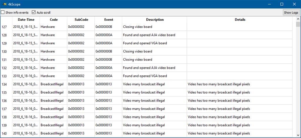
10 Globe button opens up the web page for 4KScope. The web page lets the user set up and view scopes remotely. Log button opens up the events log, which allows the user to review specific types of events, useful for troubleshooting errors or other issues.
11

12 IP Setup Window Tabs - in SMPTE 2110 there are separate Video, Audio and Ancillary sets Type pulldown menu - select the type of network video stream, SMPTE 2110 or SMPTE Receive pulldown menu - select between network transport IP version 4 or version 6 for incoming streams Source Address checkbox and field - the address of the device sending the video Source Port checkbox and field - the port on the source device sending the video Destination Address checkbox and field - the address the video is going to Destination Port checkbox and field - the port the video is going to Interface checkbox and field - the IP address of the NIC that is connected to the source device Send pulldown menu- select between network transport IP version 4 or version 6 for outgoing streams Source Address checkbox and field - the address of the device sending the video Source Port checkbox and field - the port on the source device sending the video Destination Address checkbox and field - the address the video is going to
13 Destination Port checkbox and field - the port the video is going to Interface checkbox and field - the IP address of the NIC that is connected to the source device Clock Source pulldown menu - select between Free run, internal or PTP 1588 Grandmaster Clock Master pulldown menu - select a master clock source, or auto select Data Rate field set the data rate Accept button - set any changes that have been made and close the setup dialog Cancel button - close the setup dialog without making any changes

14 Settings Window Signal Format pulldown menu - displays the current setting, and allows the user to select between the formats supported by the I/O hardware. Color Format pulldown menu - allows the user to select the processing mode. In the case of single link, this can be 8 or 10 bit YCbCr or RGBA 8. For dual link it is normally YCbCr 10 or RGB 10. Primaries select between the following primaries: SD Color Primaries HD Color Primaries
15 HDR WCG Primaries Auto - Select the correct value based on the signal format Transfer adjust the Transfer Gamma setting Picture Mode pulldown menu - allows the user to select how the conversion is done. All standard modes for up and down conversion are supported Down Convert pulldown menu - allows the user to select the output signal type. The output can match the input or be converted to another up or down signal format. Output pulldown menu - allows the user to select between available analog output formats. In SD this can be Composite, S-video or Component. For HD only component is supported. Closed Caption pulldown menu - allows the user to select which closed caption format is to be displayed, or to not display closed captions. Audio Input pulldown menu - allows the user to select between the embedded audio tracks (HDSDI or HDMI depending on input), or the AES/EBU audio inputs. On some hardware, analog audio inputs are also available. Audio Scale change the audio meter modes between RMS, Loudness 9 and Loudness 18 modes Preferred Scan Select between the following scan settings: Interlaced Progressive Segmented Frame Auto - Select the correct value based on the signal format Active Region fields allows the user to set the active region of the video signal. X1 sets the upper left pixel location, Y1 sets the lower left pixel location, X2 sets the upper right pixel location, Y2 sets the lower right pixel location. Auto Follow Input checkbox is selected, whenever the input type is changed, the settings for 4kScope are changed as well. If not checked, switching the input signal will not switch the settings. Scope Vblank by default, the waveform/vectorscopes do not use the vertical blanking area. If this is set, the vertical blank lines will be treated as active picture Audio Pairs - buttons allow the user to select the audio pair that will be monitored. Training Mode checkbox - Network Video Analyzer version 6 and greater includes a training mode for use at educational institutions that purchase Network Video Analyzer. It is also available free for personal use. In this mode, the various scopes can be accessed using internal multi pattern video to practice or learn how to use waveform monitors/vectorscopes. All of the video scopes are enabled in this mode, and it does not require any hardware. The multi patterns will generate most of the standard patterns used in video testing, in the correct color space and transfer mode, from CCIR-601, Rec.709, BT.2020 and even HDR10. If there is no AJA, BlueFish444, Blackmagic, Matrox or DirectShow video board in the system, it will go into 'Training Mode' automatically. If you have one of these boards, you can enable training mode by clicking on the Setup (the button with a gear icon) and clicking the training mode checkbox at the bottom of the settings window. The software will have to be restarted for it to enter training mode. Using Network Video Analyzer in training mode is essentially the same as using it in live mode, except that when you select a signal format, color space and transfer mode, an appropriate test multi pattern will be generated and used to feed the scope. The available patterns include:

16 NTSC Pattern PAL Pattern


17 HD Rec 709 Pattern QHD Rec HDR10 Pattern
18 QHD BT HDR10 Pattern

19 License button - Press the License button to open the licensing dialog. The top field displays the current status of the license. The User Name field allows the user to type in a first and last name during the licensing process. The Address field allows the user to type in the at which they would like to receive the site key for their license. Once the name and address fields have been filled out, pressing the Generate button populates the Site Code field with a string of alphanumeric characters. This string is the Site Code. The Site Code field is where the site code displayed during the licensing process. Ths user may select the site code and use Ctrl+C to copy it to the clipboard, or use the Copy button. The user will need to send the site code to Drastic Authorization to get a Site Key to enable the license. If the system has been set up with , pressing the Send button will open a new to Drastic Authorization, with the site code in the body of the . Once a reply containing the Site Key has been returned by Drastic Authorization, copy it, then paste it into the Site Key field either using the Paste button or Ctrl+V. Once the Site Key has been pasted into the Site Key field, pressing the Register button registers the license. The system may need to be restarted for the change in license status to be updated. Pressing the x in the upper right corner will close the License window. Press the Done button to enable any changes, and close the Settings window.
.")
20 Data View To display the Picture view, press the Data View button. The Data view allows access to the raw pixel values being monitored on the HDMI or SDI input. Values are captured and displayed in their raw values, with no manipulation by the software. Capture card ranging is maintained, supporting both and (inclusive). For YCbCr signals, the Y/Cb and Y/Cr pairs are displayed next to each other with no interpolation. For dual link RGB, the components are also displayed directly. This mode is perfect for checking vertical blank signaling and metadata, as well as picture issues like inner line sync markers or out of range colors. Pixel starts can be selected, along with lines, in the edit boxes above the data area. Pixels can also be 'picked' by clicking on the video image to set both pixel and line start. Hanging the mouse over the picture, will pop up a tool tip with the R, G and B percentage as well as the pixel X and Y position.
21 Picture To display the Picture view, press the Scope Config button. This opens the Scope Config window. Click on the Picture button on the right. This opens the Picture Setup section of the Scope Config. Select a layout. The choices are: 1 scope (single), 2 scopes (side by side), 4 scopes (2 x 2 grid), or 6 scopes (two rows of three scopes). For a multiple scope layout, click on the window in which you would like the Picture displayed. Action Safe checkbox - when selected, the Action Safe graticule is displayed over the video output. Title Safe checkbox - when selected, the Title Safe graticule is displayed over the video output. Graphic Safe checkbox - when selected, the Graphic Safe graticule is displayed over the video output. Picture Frame checkbox - when selected, the Picture Frame graticule is displayed over the video output. Active Region checkbox - when selected, the Active region graticule is displayed over the video output. Graticule Brightness slider - Moving the Graticule Brightness slider adjusts the brightness of the graticule overlay, 0% providing no display and 100% being maximum brightness. Pressing the x in the upper right corner will close the Scope Config window.

22 Here is the Picture view. The Picture view shows the video signal, to confirm the source is correct and to display time code location. Action Safe, Title Safe, Graphic Safe, Picture Safe, and Active Region graticules may be optionally overlaid.

23 Vectorscope Vectorscope Setup To display the Vectorscope view, press the Scope Config button. This opens the Scope Config window. Click on the Vectorscope button on the right. This opens the Vectorscope Setup section of the Scope Config. Select a layout. The choices are: 1 scope (single), 2 scopes (side by side), 4 scopes (2 x 2 grid), or 6 scopes (two rows of three scopes). For a multiple scope layout, click on the window in which you would like the Vectorscope displayed. Graticule checkbox when selected, the graticule is laid over the Vectorscope. The brightness of the Graticule may be adjusted using the Graticule Brightness slider described below. 100% Marks checkbox when selected, the 100% Marks are displayed over the Vectorscope 75% Marks checkbox - when selected, the 75% Marks are displayed over the Vectorscope Angle Marker checkbox - when selected, the Angle Marker is displayed over the Vectorscope Skin Tone Line checkbox - when selected, the Skin Tone Line is displayed over the Vectorscope Intensity slider Moving the Intensity slider brightens or dims the display of the video signal through the Vectorscope. The current setting is displayed above the slider, as a percentage, 0% providing no display and 100% being maximum intensity. Graticule Brightness slider - Moving the Graticule Brightness slider adjusts the brightness of the graticule overlay, 0% providing no display and 100% being maximum brightness. Pressing the x in the upper right corner will close the Scope Config window.
 at 75% and 100% saturation.")
24 Vectorscope Window Here is the Vectorscope. The Vectorscope displays a traditional Cb by Cr X-Y display with overlaid reference graticule. Color accurate graticules automatically switch between SD and HD color spaces. The markers include color points (for standard bar checks) at 75% and 100% saturation. All the standard points are boxed; red, magenta, blue, cyan, green and yellow. A skin tone/flesh line is provided to allow for easy hue adjustment as well as standard diagonals. At all times a minimum and maximum value for each of the channels (Y, Cr and Cb) is displayed in 10 bit mode (0-1023). The color of the text for each channel indicates the following: in range (green), out of range but legal (yellow) and illegal/sync values (red). For single link 8 and 10 bit YCbCr signals, there is no color processing involved. For dual link 4:4:4 RGB signals, the equivalent Cb and Cr are calculated to create the display.
25 Waveform YCbCr Waveform YCbCr Setup To display the Waveform YCbCr view, press the Scope Config button. This opens the Scope Config window. Click on the Waveform YCbCr button on the right. This opens the Waveform YCbCr Setup section of the Scope Config. Select a layout. The choices are: 1 scope (single), 2 scopes (side by side), 4 scopes (2 x 2 grid), or 6 scopes (two rows of three scopes). For a multiple scope layout, click on the window in which you would like the Waveform YCbCr displayed. Graticule checkbox when selected, the graticule is laid over the Waveform YCbCr display. The brightness of the Graticule may be adjusted using the Graticule Brightness slider described below.


26 Show Parade checkbox when selected, the display is from left to right. When not selected, the display is stacked top to bottom. Only Luma checkbox when selected, displays only the luminance of the signal. Scope White checkbox turns the display white. Intensity slider Moving the Intensity slider brightens or dims the display of the video signal through the Vectorscope. The current setting is displayed above the slider, as a percentage, 0% providing no display and 100% being maximum intensity. Graticule Brightness slider - Moving the Graticule Brightness slider adjusts the brightness of the graticule overlay, 0% providing no display and 100% being maximum brightness. Pressing the x in the upper right corner will close the Scope Config window.

27 Waveform YCbCr Window Here is the Waveform YCbCr. The YCbCr Waveform Monitor displays the levels of the Y, Cb and Cr from the left of the picture to the right of the picture with all the lines summed into one graph. The Y, or luma/luminance, graph provides accurate white and black level information, as well as the range in between. The Cb and Cr display the +/- 512 levels of chroma of both types. This provides a visual representation of the chroma range of the signal. Critical for downstream color correction is the need to ensure proper luminance levels at the stage of initial capture, so any corrections will not muddy or wash out the signal information. At all times a minimum and maximum value for each of the channels (Y, Cr and Cb) is displayed in 10 bit mode (0-1023). The color of the text for each channel indicates the following: in range (green), out of range but legal (yellow) and illegal/sync values (red).
28 Waveform RGB Waveform RGB Setup To display the Waveform RGB view, press the Scope Config button. This opens the Scope Config window. Click on the Waveform RGB button on the right. This opens the Waveform RGB Setup section of the Scope Config. Select a layout. The choices are: 1 scope (single), 2 scopes (side by side), 4 scopes (2 x 2 grid), or 6 scopes (two rows of three scopes). For a multiple scope layout, click on the window in which you would like the Waveform RGB displayed. Graticule checkbox when selected, the graticule is laid over the Waveform RGB display. The brightness of the Graticule may be adjusted using the Graticule Brightness slider described below.
, so the scale will place white at 240 and black at 16 in normal scale. If in full scale, white will be placed at 255 and black at 0.")
29 Show Parade checkbox when selected, the display is from left to right. When not selected, the display is stacked top to bottom. Full Scale checkbox RGB, by default, will be srgb. The range of each color will be from 16 to 240 (in 8 bit), so the scale will place white at 240 and black at 16 in normal scale. If in full scale, white will be placed at 255 and black at 0. Intensity slider Moving the Intensity slider brightens or dims the display of the video signal. The current setting is displayed above the slider, as a percentage, 0% providing no display and 100% being maximum intensity. Graticule Brightness slider moving the Graticule Brightness slider adjusts the brightness of the graticule overlay, 0% providing no display and 100% being maximum brightness. Pressing the x in the upper right corner will close the Scope Config window.

30 Waveform RGB Window Here is the Waveform RGB. The RGB Waveform Monitor shows each of the red, green and blue signals as independent graphs, displaying the RGB, or chrominance/color values associated with the signal. At all times a minimum and maximum value for each of the channels (R, G and B and A) is displayed in 10 bit mode (0-1023). For dual link RGB signals, the original RGB 10 bit values are used unprocessed. For single link YCbCr signals, they are first converted to RGB before being analyzed and displayed.
31 Histogram Histogram Setup To display the Histogram view, press the Scope Config button. This opens the Scope Config window. Click on the Histogram button on the right. This opens the Histogram Setup section of the Scope Config. Select a layout. The choices are: 1 scope (single), 2 scopes (side by side), 4 scopes (2 x 2 grid), or 6 scopes (two rows of three scopes). For a multiple scope layout, click on the window in which you would like the Histogram displayed. Graticule checkbox when selected, the graticule is laid over the Histogram display. The brightness of the Graticule may be adjusted using the Graticule Brightness slider described below. Luma Histogram checkbox when selected, displays the luminance of the signal. Show RGB checkbox when selected, displays the RGB portion of the signal. Graticule Brightness slider moving the Graticule Brightness slider adjusts the brightness of the graticule overlay, 0% providing no display and 100% being maximum brightness. Pressing the x in the upper right corner will close the Scope Config window.

32 Histogram Window Here is the Histogram window in RGB mode. The Histogram view shows the distribution of red, green and blue within the signal as a series of discrete bars that make a continuous graph for each color. This display provides an overview of the tonal range of each color in the picture. Each bar is the count of the number of pixels for one of the 1024 possible colors. These totals are then auto ranged to fit within the graticule and represent the relationship between the shades of each color and between each other. Each color has its own graph. The color's levels are represented from left to right, with the absolute left being 0 and the absolute right being The scale is presented as a percentage to allow for extremely bright or dark pictures to be analyzed without truncating.

33 Here is the Histogram with Luma Histogram selected, displaying only luminance information.
34 Chromaticity Chromaticity Setup To display the Chromaticity view, press the Scope Config button. This opens the Scope Config window. Click on the Chromaticity button on the right. This opens the Chromaticity Setup section of the Scope Config. Select a layout. The choices are: 1 scope (single), 2 scopes (side by side), 4 scopes (2 x 2 grid), or 6 scopes (two rows of three scopes). For a multiple scope layout, click on the window in which you would like the Chromaticity displayed. Graticule checkbox when selected, the graticule is laid over the Histogram display. The brightness of the Graticule may be adjusted using the Graticule Brightness slider described below. Triangle 601 checkbox when selected, displays the CCIR-601 triangle. Triangle 709 checkbox when selected, displays the Rec.709 triangle. Triangle 2020 checkbox when selected, displays the BT.2020 triangle. Triangle P3 checkbox when selected, displays the P3 triangle. Invert checkbox when selected, displays the video signal over a black background instead of the Chromaticity hued background. Black checkbox when selected, displays the video as black. If unselected, the video will be displayed as white. Graticule Brightness slider moving the Graticule Brightness slider adjusts the brightness of the graticule overlay, 0% providing no display and 100% being maximum brightness. Pressing the x in the upper right corner will close the Scope Config window.
 a triangle can be superimposed. This will delineate the colors that fall within the acceptable range and those that are outside it.")
35 Chromaticity Window Here is the Chromaticity window. The Chromaticity scope provides a visual representation of the color in a video across all the colors of visible light. For a particular YCbCr range (BT.2020, P3, Rec.709, CCIR-601) a triangle can be superimposed. This will delineate the colors that fall within the acceptable range and those that are outside it. The color of the video within the CIE 1931 color display can be white over black, or black over white. The amount of a color will cause that dot to be scaled from the second color to the first.
36 IP Timing Window IP Timing Setup To display the IP Timing view, press the Scope Config button. This opens the Scope Config window. Click on the IP Timing button on the right. This opens the IP Timing Setup section of the Scope Config. Select a layout. The choices are: 1 scope (single), 2 scopes (side by side), 4 scopes (2 x 2 grid), or 6 scopes (two rows of three scopes). For a multiple scope layout, click on the window in which you would like the Chromaticity displayed. Graticule checkbox when selected, the graticule is laid over the Histogram display. The brightness of the Graticule may be adjusted using the Graticule Brightness slider described below. Graticule Brightness slider moving the Graticule Brightness slider adjusts the brightness of the graticule overlay, 0% providing no display and 100% being maximum brightness. Pressing the x in the upper right corner will close the Scope Config window.

37 IP Timing Window Here is the IP Timing window. Network Video Analyzer records the timing of each incoming packet of SMPTE 2110 or SMPTE These timing records can then be analyzed for expected packet time, min/max/average packet time, packet jitter and out of order or missing packets. There is also a chart that shows a histogram of what the inter-packet timing was, and a line graph that displays how far off the expected time each packet was.
38 Status Window Status Setup To display the Status view, press the Scope Config button. This opens the Scope Config window. Click on the Status button on the right. This opens the Status Setup section of the Scope Config. Select a layout. The choices are: 1 scope (single), 2 scopes (side by side), 4 scopes (2 x 2 grid), or 6 scopes (two rows of three scopes). For a multiple scope layout, click on the window in which you would like the Status displayed. Graticule Brightness slider moving the Graticule Brightness slider adjusts the brightness of the graticule overlay, 0% providing no display and 100% being maximum brightness. Pressing the x in the upper right corner will close the Scope Config window.

39 Status Window Here is the Status window. The Status window displays: Y: Minimum and Maximum, Low and High, Average, Gamut Under, and Gamut Over values U: Minimum and Maximum, Low and High, Average, Gamut Under, and Gamut Over values V: Minimum and Maximum, Low and High, Average, Gamut Under, and Gamut Over values S: Minimum and Maximum, Low and High, Average, Gamut Under, and Gamut Over values MaxCLL In HDR10 mode, Maximum Content Light Level MaxFALL In HDR10 mode, Maximum Frame Average Light Level Line repetition in number of lines over total possible lines Broadcast illegal in percentage Audio Peak per channel pair Audio RMS per channel pair Audio Ebu Loudness per channel pair
40 Audio Vector Audio Vector Setup To display the Audio Vectorscope view, press the Scope Config button. This opens the Scope Config window. Click on the Audio Vectorscope button on the right. This opens the Audio Vectorscope Setup section of the Scope Config. Select a layout. The choices are: 1 scope (single), 2 scopes (side by side), 4 scopes (2 x 2 grid), or 6 scopes (two rows of three scopes). For a multiple scope layout, click on the window in which you would like the Audio Vectorscope displayed. Graticule checkbox when selected, the graticule is laid over the Histogram display. The brightness of the Graticule may be adjusted using the Graticule Brightness slider described below. Lissajousxy checkbox when selected, displays the relative phase of the selected audio pair in Lissajous XY mode. Lissajous checkbox when selected, displays the relative phase of the selected audio pair in Lissajous mode. Polar checkbox when selected, displays the relative phase of the selected audio pair in Polar mode. Graticule Brightness slider moving the Graticule Brightness slider adjusts the brightness of the graticule overlay, 0% providing no display and 100% being maximum brightness. Pressing the x in the upper right corner will close the Scope Config window.

41 Audio Vector Window Here is the Audio Vectorscope window. The audio vectorscope measures the difference between channels of a stereo pair. One channel drives the horizontal and the other the vertical deflection. This will show the relative phase of the two channels. This can be shown in Lissajous XY, Lissajous or Polar modes. Any pair may be selected in the setup.
42 Audio Phase Audio Phase Setup To display the Audio Phase view, press the Scope Config button. This opens the Scope Config window. Click on the Audio Phase button on the right. This opens the Audio Phase Setup section of the Scope Config. Select a layout. The choices are: 1 scope (single), 2 scopes (side by side), 4 scopes (2 x 2 grid), or 6 scopes (two rows of three scopes). For a multiple scope layout, click on the window in which you would like the Audio Phase displayed. Graticule checkbox when selected, the graticule is laid over the Histogram display. The brightness of the Graticule may be adjusted using the Graticule Brightness slider described below. Graticule Brightness slider moving the Graticule Brightness slider adjusts the brightness of the graticule overlay, 0% providing no display and 100% being maximum brightness.

43 Audio Phase Window Here is the Audio Phase window. The audio phase meter shows the relative density of two audio channels and the relative loudness as a line moving towards the louder channel.
44 Audio Histogram Audio Histogram Setup To display the Audio Histogram view, press the Scope Config button. This opens the Scope Config window. Click on the Audio Phase button on the right. This opens the Audio Histogram Setup section of the Scope Config. Select a layout. The choices are: 1 scope (single), 2 scopes (side by side), 4 scopes (2 x 2 grid), or 6 scopes (two rows of three scopes). For a multiple scope layout, click on the window in which you would like the Audio Histogram displayed. Graticule checkbox when selected, the graticule is laid over the Histogram display. The brightness of the Graticule may be adjusted using the Graticule Brightness slider described below. Amp Linear selector clicking in the Amp Linear checkbox sets the Amp to linear Amp Log selector clicking in the Amp Log checkbox sets the Amp to linear Scale Linear clicking in the Scale Linear checkbox sets the scale to linear. Scale Sqrt clicking in the Scale Sqrt checkbox sets the scale to sqrt. Scale Cbrt clicking in the Scale Cbrt checkbox sets the scale to cbrt. Scale Log clicking in the Scale Log checkbox sets the scale to logarithmic. Scale RLog clicking in the Scale Rlog checkbox sets the scale to R logarithmic. Graticule Brightness slider moving the Graticule Brightness slider adjusts the brightness of the graticule overlay, 0% providing no display and 100% being maximum brightness.

45 Audio Histogram Window Here is the Audio Histogram window. The audio histogram displays a bar chart of the levels of the components of an audio signal. This can be displayed as linear or logarithmic. The scale can be set as linear, square root, cubed root, log or reverse log.
46 Audio Wave Audio Wave Setup To display the Audio Wave view, press the Scope Config button. This opens the Scope Config window. Click on the Audio Wave button on the right. This opens the Audio Wave Setup section of the Scope Config. Select a layout. The choices are: 1 scope (single), 2 scopes (side by side), 4 scopes (2 x 2 grid), or 6 scopes (two rows of three scopes). For a multiple scope layout, click on the window in which you would like the Audio Wave displayed. Graticule checkbox when selected, the graticule is laid over the Histogram display. The brightness of the Graticule may be adjusted using the Graticule Brightness slider described below. Graticule Brightness slider moving the Graticule Brightness slider adjusts the brightness of the graticule overlay, 0% providing no display and 100% being maximum brightness.

47 Audio Wave Window Here is the Audio Wave window. The audio waveform of any pair of channels can be displayed.
48 Scope Layout Scope Config To set up the layout of the various scopes, press the Scope Config button. Along the top of the Scope Config window, there are four available layouts for the interface. Layout 1 clicking on layout 1 sets the display to use a single scope. Once this selection has been made, clicking on one of the scope selectors to the right will set the display to that scope. Layout 2 clicking on layout 2 sets the display to show two scopes of equal size side by side. Layout 3 clicking on layout 3 sets the display to show four scopes of equal size stacked in a two by two grid. Layout 4 clicking on layout 4 sets the display to show six scopes of equal size, configured in 2 rows of 3 screens each.
, and then pressing the Picture selector sets this window to display the Video signal.")
49 An Example - 4 Scopes in a 2x2 Grid In the Scope Config window, pressing the 3rd icon from the left (displayed with blue highlight to indicate selected) sets the window to use four scopes arrayed in a 2x2 grid. Clicking on the window at top left (outlined, in gray to indicate selected), and then pressing the Picture selector sets this window to display the Video signal. To set each screen: Click on the screen. Click on the desired scope's button from the selection on the right. Currently this selection includes Picture, Vector, Waveform, Waveform RGB, Histogram, Chromaticity, IP Timing, Status, Audio Vector, Audio Phase, Audio Histogram, and Audio Wave. Selecting the scope as per the previous step sets the selected screen to that scope, and displays the scope's available settings. Adjust these settings as required for the application. Once the layout has been set up, press the red x in the corner to close the Scope Config window.
50 Advanced Zoom and Pan Network Video Analyzer supports zooming the waveform monitors and vectorscope for a closer look at low saturation signals, or the luma elements of the waveform. The live picture can also be zoomed in or out, and panned with the mouse. To zoom, place the mouse over the picture or scope, and roll the mouse wheel. To pan the picture, click on it and drag it until the area of interest is visible. To reset to normal zoom, right click the mouse. Frame Compare Network Video Analyzer includes a signal compare feature that can be used to freeze a complete frame of video (two fields in interlaced), every second line (field) or at a 50/50 dissolve to compare two signals or cameras. Once frozen, all the standard scopes are still available for setup and comparison. While a frame is frozen, the comparison mode and type of scope can be changed. To access the frame compare features, press the Frame Grab button.
51 Setup Install the Software Install Network Video Analyzer software on the system. Regardless of the delivery method, the software will be available at some level as an (executable) installable file. Double-click on the file, or right click and select Open from the context menu. Follow the prompts to set where the software should be installed and make other installation-specific decisions. To take full advantage of the hardware output features of Network Video Analyzer, the system should contain one of the supported AJA, Blackmagic, Matrox or Bluefish444 boards. The board's manufacturers will have up to date recommendations for system specifications. License the Software Network Video Analyzer installs in demo mode, with various limitations. To remove these limitations, you will need a valid license. To request a license, you will need to run the license app, generate a site code and it to us at: authorization@drastictech.com We will send back a site key to provide a temp license. Prior to purchase, this license will be temporary. There is detailed step by step information on licensing at the following location: Run the Software Run the software. If the default installation path is used, you can open it at: Start Programs Drastic Network Video Analyzer Network Video Analyzer. The software will then need to be set up. Setup Window Confirm that the signal you wish to monitor is connected to the correct input(s) of the video board. Click on the Setup button to confirm or adjust any settings for the type of signal format being used. Once the system is correctly set up, pressing the Done button closes the Setup window.
52 Operations Network Video Analyzer can be used to view an input signal through a standard NIC or supported AJA or Matrox IP video hardware. Once a capable system has been equipped with an install of Network Video Analyzer, the user may connect a signal to the appropriate network streams and begin to use the software. Use the Setup Window to confirm or adjust any settings for your video signal. Use the Scope Config window to set the layout (number and arrangement of windows), and which window uses which scope. At this point if all has been properly set up, the user should be able to view their signal through the appropriate scopes and other signal analysis tools.
53 This manual has been compiled to assist the user in their experience using Network Video Analyzer software. It is believed to be correct at the time of writing, and every effort has been made to provide accurate and useful information. Any errors that may have crept in are unintentional and will hopefully be purged in a future revision of this document. We welcome your feedback. Drastic Technologies Ltd 523 The Queensway, Suite 102 Toronto, ON, M8Y 1J7 Canada (416) (416) (c)opyright 2018, Drastic Technologies Ltd. All Rights Reserved.
sdiscope Signal Analysis Software Version 6
 sdiscope Signal Analysis Software Version 6 Table of Contents About sdiscope...3 Reference...5 Main Interface Overview...5 Settings Window...11 Data View...16 Picture...17 Vectorscope...19 Vectorscope
4kScope Signal Analysis Software Version 6
 4kScope Signal Analysis Software Version 6 Table of Contents About 4kScope...4 Reference...5 Main Interface Overview...5 Settings Window...7 Data View...13 Picture...14 Vectorscope...16 Vectorscope Setup...16
4KScope Software Waveform, Vectorscope, Histogram and Monitor
 4KScope - a 4K/2K/HD/SD Video Measurement Tool View your color bars, test patterns, live camera or telecine signal for device or facility installation, setup, commissioning/certification and other operational
Ultra TQ V3.4 Update 4KTQ Ultra TQ Update 1
 Ultra TQ Ultra TQ Update 1 About this Document Notice This documentation contains proprietary information of Omnitek. No part of this documentation may be reproduced, stored in a retrieval system or transmitted
MultiScopeLite. Users Guide. Video Measurement and Calibration Tools. RHMG Software Tools Library 1/18/2013. Bill and Scott Werba
 MultiScopeLite Video Measurement and Calibration Tools Users Guide RHMG Software Tools Library 1/18/2013 Authors: Bill and Scott Werba Developer: Scott Werba Document ID: 3000-001 Revision: v1.0.4 Publication
OmniTek
 OmniTek www.omnitek.tv Advanced Measurement Technology OTR 1001 Advanced Waveform Rasterizer, Signal Generator, Stereo 3D Monitor, Picture Quality Analyzer 3Gb/s Dual-Link HD SD 1RU chassis Introducing
Click on the chapter below to navigate to the corresponding section of this document.
 The following are delivery specifications for PANDA 23 both physical and digital. Regardless of delivery method the following specifications must be adhered to in order to run programming on PANDA 23.
AX20. Atlas 19.5" 3G-SDI/HDMI Field and Studio Monitor with 3D LUTs & Scopes. Quick Start Guide. What s Included CHECKED BY
 AX20 Quick Start Guide Atlas 19.5" 3G-SDI/HDMI Field and Studio Monitor with 3D LUTs & Scopes What s Included 1 x Atlas 19.5" Monitor 1 x AC Adapter 1 x Sunhood CHECKED BY AX20 FRONT 1920 x 1080 19.5 inch
Operating Instructions
 Broadcast A/V Division Model No. M-LYNX-702W Dual 7 High Resolution Rack Mount Display with Waveform Operating Instructions V.1.0 Table of Contents 1. PRODUCT DESCRIPTION... 3 2. MENU SETTING... 6 3. SPECIFICATIONS...
Monitoring HD and SD Color Gamut in a Broadcast Environment
 Monitoring HD and SD Color Gamut in a Broadcast Environment Basics of RGB and composite color space, introducing an efficient way to monitor color gamut problems #1 The RGB Principle With 3 light sources
Color Correction in Final Cut Studio Introduction to Color
 Color Correction in Final Cut Studio Introduction to Color Part 1: Getting Started with Color Part 2: Managing and Applying Grades upart 3: Using the Scopes and Auto Balanceo Part 4: Copying from One Clip
2018 Teradek, LLC. All Rights Reserved. REFERENCE GUIDE
 2018 Teradek, LLC. All Rights Reserved. REFERENCE GUIDE TABLE OF CONTENTS 1. INTRODUCTION... 3 Support Resources... 3 Disclaimer... 3 User Interface... 3 2. GETTING STARTED... 5 Configure a Camera Source...
Test Equipment Depot Washington Street Melrose, MA TestEquipmentDepot.com
 Test Equipment Depot - 800.517.8431-99 Washington Street Melrose, MA 02176 - TestEquipmentDepot.com Read this first Product documentation Covered products The following Tektronix products are covered by
Table of Contents ccconvert...1 verifycc...12 ccreview...14
 ccconvert 1 Table of Contents ccconvert...1 Controls and Displays...3 Extract...3 Embed...6 How to Use ccconvert...9 Setup...9 Connect Hardware...9 Install Software...9 Licensing...10 un ccconvert...11
Calibrating the timecode signal input
 Chapter 5 Calibrating the timecode signal input Computer hardware can introduce an offset between the timecode signal and the video signal, which causes the timecode and video to be offset when they are
OPERATING GUIDE. M-Vision Cine 3D series. High Brightness Digital Video Projector 16:9 widescreen display. Rev A August A
 OPERATING GUIDE M-Vision Cine 3D series High Brightness Digital Video Projector 16:9 widescreen display 112-022A Digital Projection M-Vision Cine 3D series CONTENTS Operating Guide CONTENTS About this
SX7. Saga 7" Super Bright HDMI/3G-SDI Field Monitor with 3D-LUTs. Quick Start Guide. What s Included CHECKED BY
 SX7 Quick Start Guide Saga 7" Super Bright HDMI/3G-SDI Field Monitor with 3D-LUTs What s Included 1 x Saga X7 Monitor 1 x V-Mount Plate (Attached) 1 x Mini-XLR to P-TAP Cable 1 x Dual Sony L Battery Adapter
MediaNXS. Drastic DDR Software User Guide Drastic Technologies Ltd. All Rights Reserved
 MediaNXS Drastic DDR Software User Guide 2009 Drastic Technologies Ltd. All Rights Reserved Information in this document is subject to change without notice and does not represent a commitment on the part
Revised for July Grading HDR material in Nucoda 2 Some things to remember about mastering material for HDR 2
 Revised for 2017.1 July 2017 Grading HDR material in Nucoda Grading HDR material in Nucoda 2 Some things to remember about mastering material for HDR 2 Technical requirements for mastering at HDR 3 HDR
OPERATING GUIDE. HIGHlite 660 series. High Brightness Digital Video Projector 16:9 widescreen display. Rev A June A
 OPERATING GUIDE HIGHlite 660 series High Brightness Digital Video Projector 16:9 widescreen display 111-9714A Digital Projection HIGHlite 660 series CONTENTS Operating Guide CONTENTS About this Guide...
Ultra 4K Tool Box. Version Release Note
 Ultra 4K Tool Box Version 2.1.43.0 Release Note This document summarises the enhancements introduced in Version 2.1 of the software for the Omnitek Ultra 4K Tool Box and related products. It also details
Projector Management Application Version 7.00 Instruction Guide
 Projector Management Application Version 7.00 Instruction Guide Contents 1 INTRODUCTION... 4 1.1 OUTLINE... 4 1.2 SYSTEM... 4 2 INSTALLATION... 5 2.1 SYSTEM REQUIREMENTS... 5 2.2 PROJECTOR MANAGEMENT APPLICATION
LV 58SER06 3G-SDI INPUT INSTRUCTION MANUAL
 LV 58SER06 3G-SDI INPUT INSTRUCTION MANUAL Contents 1. INTRODUCTION... 1 1.1 Scope of Warranty... 1 1.2 Operating Precautions... 1 1.2.1 Maximum Allowable Input Voltage... 1 1.2.2 Shorting and Applying
31 4K / UHD HDR Reference Monitor
 31 4K / UHD HDR Reference Monitor HDR : PQ, HLG, S-Log3 1,000cd/m² High Brighthness 1,000,000:1 High Contrast ratio 12G-SDI Single Link 4K 6G-SDI Dual Link 2-S.I. 4K 3G-SDI Quad Link Square Division &
Introduction 2. The Veescope Live Interface 3. Trouble Shooting Veescope Live 10
 Introduction 2 The Veescope Live Interface 3 Inputs Tab View 3 Record/Display Tab View 4 Patterns Tab View 6 Zebras Sub Tab View 6 Chroma Key Sub View 6 Scopes Tab View 8 Trouble Shooting Veescope Live
Statement SmartLCT User s Manual Welcome to use the product from Xi an NovaStar Tech Co., Ltd. (hereinafter referred to as NovaStar ). It is our great
. It is our great") LED Display Configuration Software SmartLCT User s Manual Software Version: V3.0 Rev3.0.0 NS110100239 Statement SmartLCT User s Manual Welcome to use the product from Xi an NovaStar Tech Co., Ltd. (hereinafter
LED Display Configuration Software SmartLCT User s Manual Software Version: V3.0 Rev3.0.0 NS110100239 Statement SmartLCT User s Manual Welcome to use the product from Xi an NovaStar Tech Co., Ltd. (hereinafter
MultiScopeCompact 3D Video Measurement, Analysis and Calibration Tools
 MultiScopeCompact 3D Video Measurement, Analysis and Calibration Tools Users Guide RHMG Software Tools Library Authors: Developer: Document ID: Revision: Publication Date: Publication Status: Bill and
ENC ENC-1103 SDI to Composite/CAV/RGB Encoder Guide to Installation and Operation M July 2008 DESCRIPTION FUNCTIONAL BLOCK DIAGRAM
 M756-9600-100 July 2008 DESCRIPTION The is a high-quality encoder with 12-bit conversion allowing operators to convert a SDI signal to Composite, CAV or RGB. The composite outputs can be NTSC, PAL or PAL-M
Discreet Logic Inc., All Rights Reserved. This documentation contains proprietary information of Discreet Logic Inc. and its subsidiaries.
 Discreet Logic Inc., 1996-2000. All Rights Reserved. This documentation contains proprietary information of Discreet Logic Inc. and its subsidiaries. No part of this documentation may be reproduced, stored
smallhd 703 UltraBright
 smallhd 703 UltraBright Display Panel Type LTPS LCD Size Diagonal 7.02 Resolution 1920 x 1080 Pixel Density (PPI) 323 ppi Aspect Ratio 16:09 Active Area 7.02 Brightness 2500 Contrast 1200:1 as per data
Operating Instructions
 Marshall Electronics Model No. V-R171X-DLW 17" Full Resolution Dual Link / Waveform Monitor Operating Instructions 2 This page intentionally left blank Contents Features... 4 Installation and Initial Setup...
PYROPTIX TM IMAGE PROCESSING SOFTWARE
 Innovative Technologies for Maximum Efficiency PYROPTIX TM IMAGE PROCESSING SOFTWARE V1.0 SOFTWARE GUIDE 2017 Enertechnix Inc. PyrOptix Image Processing Software v1.0 Section Index 1. Software Overview...
Bright. Sharp. Brilliant.
 Bright. Sharp. Brilliant. The Gratical HD Micro-OLED Electronic Viewfinder Full Digital Manual Table of Contents Gratical Features...3 Included Components...4 Battery Usage...4 Power Sources...4 HDSDI
IP LIVE PRODUCTION UNIT NXL-IP55
 IP LIVE PRODUCTION UNIT NXL-IP55 OPERATION MANUAL 1st Edition (Revised 2) [English] Table of Contents Overview...3 Features... 3 Transmittable Signals... 3 Supported Networks... 3 System Configuration
Operating Instructions
 Marshall Electronics Broadcast A/V Division Model No. VSW-2200 4-Input Seamless SDI A/V Switcher Operating Instructions Table of Contents 1. Overview... 2. Features.... Package Contents... 4. Specifications...
Marshall Electronics. Model V-R173-DLW 17.3 Rack Mount Monitor with Waveform Monitor. Operating Instructions
 Marshall Electronics Model V-R173-DLW 17.3 Rack Mount Monitor with Waveform Monitor Operating Instructions Page intentionally left blank 2 Operating Instructions 7/15/2015 Table of Contents Installation
9" Portable On-camera LCD Monitor. User Manual. Model: DT-X91F HDSDI&HDMI, Waveform, Audio meter, Focus assist DT-X91H 3GSDI&HDMI DT-X91C HDMI
 9" Portable On-camera LCD Monitor User Manual Model: DT-X91F HDSDI&HDMI, Waveform, Audio meter, Focus assist DT-X91H DT-X91C 3GSDI&HDMI HDMI Please read this User Manual throughout before using. Preface
DRAFT RELEASE FOR BETA EVALUATION ONLY
 IPM-16 In-Picture Audio Metering User Manual DRAFT RELEASE FOR BETA EVALUATION ONLY Ver 0.2 April 2013 1 Contents Introduction...3 In Picture Audio Meter Displays...4 Installation...7 External Audio Board
Import and quantification of a micro titer plate image
 BioNumerics Tutorial: Import and quantification of a micro titer plate image 1 Aims BioNumerics can import character type data from TIFF images. This happens by quantification of the color intensity and/or
Model 7405 High Definition Test Signal Generator Data Pack
 Model 7405 High Definition Test Signal Generator Data Pack E NSEMBLE D E S I G N S Revision 1.1 SW v1.1.0 This data pack provides detailed installation, configuration and operation information for the
Table of content. Table of content Introduction Concepts Hardware setup...4
 Table of content Table of content... 1 Introduction... 2 1. Concepts...3 2. Hardware setup...4 2.1. ArtNet, Nodes and Switches...4 2.2. e:cue butlers...5 2.3. Computer...5 3. Installation...6 4. LED Mapper
Advanced Waveform Monitor and Signal Generator 3Gb/s * Dual-Link * HD * SD * Standard case
 www.omnitek.tv Advanced Measurement Technology Advanced Waveform Monitor and Signal Generator 3Gb/s * Dual-Link * HD * SD * Standard case Introducing the OmniTek OTM 1000 waveform monitor and signal generator:
LV 58SER04 MPEG DECODER INSTRUCTION MANUAL USO RESTRITO
 LV 58SER04 MPEG DECODER INSTRUCTION MANUAL TABLE OF CONTENTS 1. INTRODUCTION... 1 1.1 Maximum Allowable Input Voltage... 1 1.2 Trademark Acknowledgments... 1 1.3 Notations Used in This Manual... 1 2. SPECIFICATIONS...
IP LIVE PRODUCTION UNIT NXL-IP55 USO RESTRITO. OPERATION MANUAL 1st Edition (Revised 2) [English]
![IP LIVE PRODUCTION UNIT NXL-IP55 USO RESTRITO. OPERATION MANUAL 1st Edition (Revised 2) [English]](/thumbs/89/99059597.jpg "IP LIVE PRODUCTION UNIT NXL-IP55 USO RESTRITO. OPERATION MANUAL 1st Edition (Revised 2) [English]") IP LIVE PRODUCTIO UIT XL-IP55 USO RESTRITO OPERATIO MAUAL 1st Edition (Revised 2) [English] Table of Contents Overview... 3 Features... 3 Transmittable Signals... 3 Supported etworks... 3 System Configuration
IP LIVE PRODUCTIO UIT XL-IP55 USO RESTRITO OPERATIO MAUAL 1st Edition (Revised 2) [English] Table of Contents Overview... 3 Features... 3 Transmittable Signals... 3 Supported etworks... 3 System Configuration
EDL8 Race Dash Manual Engine Management Systems
 Engine Management Systems EDL8 Race Dash Manual Engine Management Systems Page 1 EDL8 Race Dash Page 2 EMS Computers Pty Ltd Unit 9 / 171 Power St Glendenning NSW, 2761 Australia Phone.: +612 9675 1414
Operating Instructions
 Marshall Electronics Model No. V-R261-DLW 26" Full Resolution Dual Link / Waveform Monitor Operating Instructions 2 This page intentionally left blank Contents Features...4 Installation and Initial Setup...5
LedSet User s Manual V Official website: 1 /
 LedSet User s Manual V2.6.1 1 / 42 20171123 Contents 1. Interface... 3 1.1. Option Menu... 4 1.1.1. Screen Configuration... 4 1.1.1.1. Instruction to Sender/ Receiver/ Display Connection... 4 1.1.1.2.
Model 7500 HD Video Processing Frame Synchronizer Data Pack
 Model 7500 HD Video Processing Frame Synchronizer Data Pack E NSEMBLE D E S I G N S Revision 2.1 SW v2.2.0 This data pack provides detailed installation, configuration and operation information for the
METADATA CHALLENGES FOR TODAY'S TV BROADCAST SYSTEMS
 METADATA CHALLENGES FOR TODAY'S TV BROADCAST SYSTEMS Randy Conrod Harris Corporation Toronto, Canada Broadcast Clinic OCTOBER 2009 Presentation1 Introduction Understanding metadata such as audio metadata
FS3. Quick Start Guide. Overview. FS3 Control
 FS3 Quick Start Guide Overview The new FS3 combines AJA's industry-proven frame synchronization with high-quality 4K up-conversion technology to seamlessly integrate SD and HD signals into 4K workflows.
Qx IP Qx 12G IP, 4K/UHD + HDR generation, analysis & monitoring
 Qx IP Qx 12G IP, 4K/UHD + HDR generation, analysis & monitoring Qx IP Qx 12G IP, 4K/UHD + HDR generation, analysis & monitoring The Qx range brings together all the advanced, hybrid IP/SDI test & measurement
SIERRA VIDEO SP-14 SETUP GUIDE. User s Manual
 SIERRA VIDEO SP-14 SETUP GUIDE User s Manual SP-14 Setup Guide Version S 1.0 1 Contents Introduction 3 The Basic System 4 Flexible Connectivity 5 Control via Front Panel Buttons 6 Set Scaler Functions
Delvcam DELV-HSW5-CC User Guide
 Delvcam DELV-HSW5-CC User Guide 5.5" HD IPS Video Monitor with HDMI/SDI Cross Conversion & Waveform/Vectorscope IMPORTANT SAFETY INSTRUCTIONS Read manual before using this product. Keep manual for future
TERMINOLOGY INDEX. DME Down Stream Keyer (DSK) Drop Shadow. A/B Roll Edit Animation Effects Anti-Alias Auto Transition
 Drop Shadow. A/B Roll Edit Animation Effects Anti-Alias Auto Transition") A B C A/B Roll Edit Animation Effects Anti-Alias Auto Transition B-Y Signal Background Picture Background Through Mode Black Burst Border Bus Chroma/Chrominance Chroma Key Color Bar Color Matte Component
A B C A/B Roll Edit Animation Effects Anti-Alias Auto Transition B-Y Signal Background Picture Background Through Mode Black Burst Border Bus Chroma/Chrominance Chroma Key Color Bar Color Matte Component
Colour Features in Adobe Creative Suite
 Colour Features in Adobe Creative Suite HSB Based on the human perception of color, the HSB model describes three fundamental characteristics of color: Hue, Saturation, Brightness Hue Color reflected from
User Manual. 7" Portable On-camera LCD Monitor DT-X71H DT-X71C. Model: DT-X71F HDSDI&HDMI, Waveform, Audio meter, Focus assist HDSDI&HDMI HDMI
 7" Portable On-camera LCD Monitor User Manual Model: DT-X71F HDSDI&HDMI, Waveform, Audio meter, Focus assist DT-X71H DT-X71C HDSDI&HDMI HDMI Please read this User Manual throughout before using. Preface
Installation and Operation Manual. SmartView & SmartScope
 Installation and Operation Manual SmartView & SmartScope November 2017 Welcome! We hope you share our dream for the television industry to become a truly creative industry by allowing anyone to have access
CIE CIE
 U S E R M A N U A L Table of Contents Welcome to ColorFacts... 4 Installing ColorFacts... 5 Checking for ColorFacts Updates... 5 ColorFacts Registration... 6 ColorFacts Dongle... 6 Uninstalling ColorFacts...
Getting Started. Connect green audio output of SpikerBox/SpikerShield using green cable to your headphones input on iphone/ipad.
 Getting Started First thing you should do is to connect your iphone or ipad to SpikerBox with a green smartphone cable. Green cable comes with designators on each end of the cable ( Smartphone and SpikerBox
Model 7550 HD/SD Video Processing Frame Synchronizer Data Pack
 Model 7550 HD/SD Video Processing Frame Synchronizer Data Pack E NSEMBLE D E S I G N S Revision 2.1 SW v2.2.3 This data pack provides detailed installation, configuration and operation information for
Getting started with Spike Recorder on PC/Mac/Linux
 Getting started with Spike Recorder on PC/Mac/Linux You can connect your SpikerBox to your computer using either the blue laptop cable, or the green smartphone cable. How do I connect SpikerBox to computer
LCD Racks Monitor PRM-483A MULTI-CHANNEL LCD MONITOR
 LCD Racks Monitor PRM-483A MULTI-CHANNEL LCD MONITOR Contents PRM-483A Warnings... 3 Features... 4 Name & Function of Each Part... 5 OSD Menu Organization & Adjustment... 7 Other Functions... 14 System
Mobile DTV Viewer. User Manual. Mobile DTV ATSC-M/H DVB-H 1Seg. Digital TV ATSC DVB-T, DVB-T2 ISDB-T V 4. decontis GmbH Sachsenstr.
 Mobile DTV ATSC-M/H DVB-H 1Seg Digital TV ATSC DVB-T, DVB-T2 ISDB-T V 4 decontis GmbH Sachsenstr. 8 02708 Löbau Germany +49 3585 862915 +49 3585 415629 www.com dvbsam@com 1 Introduction... 5 2 System Requirements...
Multi SDI/HDMI Monitor
 99 Washington Street Melrose, MA 02176 Phone 781-665-1400 Toll Free 1-800-517-8431 Visit us at www.testequipmentdepot.com MULTI SDI/HDMI MONITOR LV 5382 Multi SDI/HDMI Monitor GENERAL The LV 5382 is a
INSTALATION AND OPERATION MANUAL ABYSSAL OS Overlay Module Version 1.3
 INSTALATION AND OPERATION MANUAL ABYSSAL OS Overlay Module Version 1.3 Thank you for purchasing the Abyssal OS Overlay Module for your ROV. This instruction manual contains all the information you ll need
HD-SDI Express User Training. J.Egri 4/09 1
 HD-SDI Express User Training J.Egri 4/09 1 Features SDI interface Supports 720p, 1080i and 1080p formats. Supports SMPTE 292M serial interface operating at 1.485 Gbps. Supports SMPTE 274M and 296M framing.
User Manual VM700T Video Measurement Set Option 30 Component Measurements
 User Manual VM700T Video Measurement Set Option 30 Component Measurements 070-9654-01 Test Equipment Depot - 800.517.8431-99 Washington Street Melrose, MA 02176 - FAX 781.665.0780 - TestEquipmentDepot.com
LV 58SER01A LV 58SER01
 LV 58SER01A LV 58SER01 SDI INPUT INSTRUCTION MANUAL Contents 1. INTRODUCTION... 1 1.1 Maximum Allowable Input Voltage to the Input Connector... 1 1.2 Precautions Concerning the Unit... 1 1.3 Notations
Delvcam DELV-HD7-4K User Guide
 Delvcam DELV-HD7-4K User Guide 7" 4K Compatible 1080P Camera Top Monitor with Audio Meter IMPORTANT SAFETY INSTRUCTIONS Read manual before using this product. Keep manual for future reference. Do not place
DETEXI Basic Configuration
 DETEXI Network Video Management System 5.5 EXPAND YOUR CONCEPTS OF SECURITY DETEXI Basic Configuration SETUP A FUNCTIONING DETEXI NVR / CLIENT It is important to know how to properly setup the DETEXI software
Preventing Illegal Colors
 Test Equipment Depot - 800.517.8431-99 Washington Street Melrose, MA 02176 - TestEquipmentDepot.com Preventing Illegal Colors Application Note Color gamut compliance is important to ensure faithful reproduction
GRATICAL EVF. Bright. Sharp. Brilliant. The Gratical HD/LT Micro-OLED Electronic Viewfinder User Manual.
 Bright. Sharp. Brilliant The Gratical HD/LT Micro-OLED Electronic Viewfinder User Manual www.zacuto.com Table of Contents Gratical Features...3-4 Included Components...3 Battery Usage...5 Power Sources...5
Matrox PowerStream Plus
 Matrox PowerStream Plus User Guide 20246-301-0100 2016.12.01 Contents 1 About this user guide...5 1.1 Using this guide... 5 1.2 More information... 5 2 Matrox PowerStream Plus software...6 2.1 Before you
INSTALATION AND OPERATION MANUAL ABYSSAL OS Overlay Module Version 1.0.1
 INSTALATION AND OPERATION MANUAL ABYSSAL OS Overlay Module Version 1.0.1 Thank you for purchasing the Abyssal OS Overlay Module for your ROV. This instruction manual contains all the information you ll
ScopeBox 2.0. A Whole New Box of Tricks
 ScopeBox 2.0 A Whole New Box of Tricks ScopeBox 2.0 copyright 2008 divergent media, inc. All rights reserved. iii Table of Contents Contents 1 Welcome to ScopeBox 2.0 1 Welcome. 1 What s new in 2.0. 1
AL37219C-EVB-A2 Evaluation Board
 AL37219C-EVB-A2 Evaluation Board User Manual Version 1.1 INFORMATION FURNISHED BY AVERLOGIC IS BELIEVED TO BE ACCURATE AND RELIABLE. HOWEVER, NO RESPONSIBILITY IS ASSUMED BY AVERLOGIC FOR ITS USE, OR FOR
Delvcam DELV-HD7-HSC User Guide
 Delvcam DELV-HD7-HSC User Guide 7" HD LCD Video Monitor with HDMI/SDI Cross Conversion & Waveform/Vectorscope IMPORTANT SAFETY INSTRUCTIONS Read manual before using this product. Keep manual for future
Spearhead Display. How To Guide
 Spearhead Display The Tektronix color tool set has always been about allowing the user to marry the Art & Science irrespective of the color space they are working in. How To Guide How To Guide Figure 1.
Patterns Manual September 16, Main Menu Basic Settings Misc. Patterns Definitions
 Patterns Manual September, 0 - Main Menu Basic Settings Misc. Patterns Definitions Chapters MAIN MENU episodes through, and they used an earlier AVS HD 0 version for the demonstrations. While some items,
2 Select the magic wand tool (M) in the toolbox. 3 Click the sky to select that area. Add to the. 4 Click the Quick Mask Mode button(q) in
 in the toolbox. 3 Click the sky to select that area. Add to the. 4 Click the Quick Mask Mode button(q) in") ADOBE PHOTOSHOP 4.0 FUNDAMENTALS A mask works like a rubylith or frisket, covering part of the image and selecting the rest. In Adobe Photoshop, you can create masks using the selection tools or by painting
ADOBE PHOTOSHOP 4.0 FUNDAMENTALS A mask works like a rubylith or frisket, covering part of the image and selecting the rest. In Adobe Photoshop, you can create masks using the selection tools or by painting
ESI VLS-2000 Video Line Scaler
 ESI VLS-2000 Video Line Scaler Operating Manual Version 1.2 October 3, 2003 ESI VLS-2000 Video Line Scaler Operating Manual Page 1 TABLE OF CONTENTS 1. INTRODUCTION...4 2. INSTALLATION AND SETUP...5 2.1.Connections...5
Bright. Sharp. Brilliant.
 Bright. Sharp. Brilliant. The Gratical HD Micro-OLED Electronic Viewfinder Full Digital Manual Table of Contents Gratical Features...3 Included Components...4 Battery Usage...4 Power Sources...4 HDSDI
SM02. High Definition Video Encoder and Pattern Generator. User Manual
 SM02 High Definition Video Encoder and Pattern Generator User Manual Revision 0.2 20 th May 2016 1 Contents Contents... 2 Tables... 2 Figures... 3 1. Introduction... 4 2. acvi Overview... 6 3. Connecting
HLE-2153G MULTI FORMAT LCD COLOR MONITOR
 MODEL HLE-2153G MULTI FORMAT LCD COLOR MONITOR OPERATON MANUAL 1 Contents Getting Started Caution Product features Monitor View Initial Setup Basic Information Connections Connecting to BNC Signal Device
Model 7130 HD Downconverter and Distribution Amplifier Data Pack
 Model 7130 HD Downconverter and Distribution Amplifier Data Pack E NSEMBLE D E S I G N S Revision 1.0 SW v1.0 www.ensembledesigns.com 7130-1 Contents MODULE OVERVIEW 3 Audio Handling 3 Control 3 Metadata
Essence of Image and Video
 1 Essence of Image and Video Wei-Ta Chu 2009/9/24 Outline 2 Image Digital Image Fundamentals Representation of Images Video Representation of Videos 3 Essence of Image Wei-Ta Chu 2009/9/24 Chapters 2 and
ARRI Look Creator. Quick Guide / Release Notes for Open Beta Test v1.0
 ARRI Look Creator Quick Guide / Release Notes for Open Beta Test v1.0 Introduction Starting with ALEXA Software Update Packet (SUP) 4.0, ARRI ALEXA cameras can apply userdefined looks to customize the
Installation and Operation Manual. Teranex Processors
 Installation and Operation Manual Teranex Processors February 2016 Welcome Thank you for purchasing a Blackmagic Design Teranex converter for your facility. The Teranex converter you have purchased is
TECHNICAL SUPPLEMENT FOR THE DELIVERY OF PROGRAMMES WITH HIGH DYNAMIC RANGE
 TECHNICAL SUPPLEMENT FOR THE DELIVERY OF PROGRAMMES WITH HIGH DYNAMIC RANGE Please note: This document is a supplement to the Digital Production Partnership's Technical Delivery Specifications, and should
OmniTek
 OmniTek www.omnitek.tv Advanced Measurement Technology OTM 1000 Advanced Waveform Monitor & Signal Generator 3Gb/s Dual-Link HD SD Standard case Introducing the OTM 1000... The OmniTek OTM 1000 offers
ELSA WINNER Series M a n u a l
 Manual Series 2002 Neue ELSA GmbH, Aachen (Germany) While the information in this manual has been compiled with great care, it may not be deemed an assurance of product characteristics. Neue ELSA GmbH
FS1-X. Quick Start Guide. Overview. Frame Rate Conversion Option. Two Video Processors. Two Operating Modes
 FS1-X Quick Start Guide Overview Matching up and synchronizing disparate video and audio formats is a critical part of any broadcast, mobile or post-production environment. Within its compact 1RU chassis,
Model: DT-X24H 23.8" Broadcast Studio LCD Monitor. User Manual. Ver:V1.0.0V00. Please read this User Manual throughout before using.
 Model: DT-X24H 23.8" Broadcast Studio LCD Monitor User Manual Ver:V1.0.0V00 Please read this User Manual throughout before using. Preface Congratulations on your purchase of this product. Please read this
New Standards That Will Make a Difference: HDR & All-IP. Matthew Goldman SVP Technology MediaKind (formerly Ericsson Media Solutions)
") New Standards That Will Make a Difference: HDR & All-IP Matthew Goldman SVP Technology MediaKind (formerly Ericsson Media Solutions) HDR is Not About Brighter Display! SDR: Video generally 1.25x; Cinema
New Standards That Will Make a Difference: HDR & All-IP Matthew Goldman SVP Technology MediaKind (formerly Ericsson Media Solutions) HDR is Not About Brighter Display! SDR: Video generally 1.25x; Cinema
Getting Started Guide for the V Series
 product pic here Getting Started Guide for the V Series Version 9.0.6 March 2010 Edition 3725-24476-003/A Trademark Information POLYCOM, the Polycom Triangles logo and the names and marks associated with
To show the Video Scopes, click on the down arrow next to View located in the upper- right corner of your playback panel.
 1 FCPX: 3.3 COLOR CORRECTION Color Correcting and Color Grading are usually the last things you do before exporting your video. Color Correcting is the process of achieving the correct, natural color of
Nintendo. January 21, 2004 Good Emulators I will place links to all of these emulators on the webpage. Mac OSX The latest version of RockNES
 98-026 Nintendo. January 21, 2004 Good Emulators I will place links to all of these emulators on the webpage. Mac OSX The latest version of RockNES (2.5.1) has various problems under OSX 1.03 Pather. You
PHABRIX SxE. PHABRIX SxD. PHABRIX Sx. Generator/Analyser/ Monitor/EYE and JITTER +AES. Generator/Analyser/ Monitor/Dual Link. Generator/Analyser/
 Leader Electronics is proud to represent the Phabrix product line in Asia. This new solution provider for Leader Electronics, Phabrix, introduced their new Phabrix SXE along with several options and upgrades
MSP 200PRO Quick Start
 MSP 200PRO Quick Start Touch Screen control Output a range of signal types Set and select from a range of common output formats Audio output test included Genlock Y&HS outputs Input live signals for preview
SingMai Electronics SM06. Advanced Composite Video Interface: HD-SDI to acvi converter module. User Manual. Revision 0.
 SM06 Advanced Composite Video Interface: HD-SDI to acvi converter module User Manual Revision 0.4 1 st May 2017 Page 1 of 26 Revision History Date Revisions Version 17-07-2016 First Draft. 0.1 28-08-2016