Installation / Operation Manual Manual code: Manual version: 0808 Software version: Innova 40i / 40i-B
|
|
|
- Donald Harvey
- 5 years ago
- Views:
Transcription


1 Installation / Operation Manual Manual code: Manual version: 0808 Software version: 2.00 Innova 40i / 40i-B
2 INDEX 1 DRO description Front plate: Main screen description: Function bar description: Turning the unit on and off DRO operation in MILL mode Display modes mm/inch inc / abs Absolute mode: Incremental mode: Tools and references: Tools: Tool change: Set a new tool in the table: Tool compensation: Reference: Changing the reference: Setting part zero (datum) as instructed by the assistant: Setting part zero (datum) without using the assistant: Searching the center of a part: Special functions Bolt-hole drilling Linear drilling Grid pattern drilling Go to: Calculator function Simulation / execution special modes: Cycle simulation: Cycle execution: DRO operation in LATHE mode Display modes mm/inch rad/diam inc / abs Absolute mode: Incremental mode: Tool: Tool setting: Setting the tool by touching a part of known diameter: Setting the tool by touching a part of unknown diameter: View tool table: Special functions Angle measurement Turning function Calculator function i - Installation/Operation - (1/26)
3 4 DRO installation Mounting on the support arm Mounting of the built-in model Rear panel General technical characteristics Connections Connection of the feedback systems Power and machine connection Installation parameters User parameters: Language Screen color Installer parameters DRO: Feedback: Compensation: Test mode Appendix UL seal CE seal Declaration of conformity Safety conditions Warranty terms Material returning terms...26 IMPORTANT NOTE: Some of the features described in this manual may not be available in this version. Consult with the Fagor Automation branch office nearest you. 40i - Installation/Operation - (2/26)
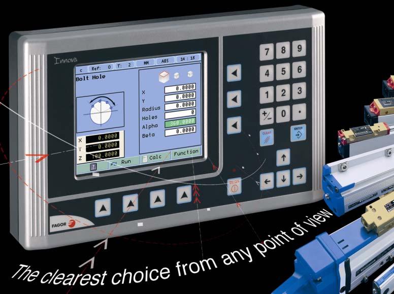
4 1 DRO description 1.1 Front plate: * Select axes * Delete axis. * Preset Keys for entering numeric values TFT screen Toggle between Z, Z1 and Z2 in lathe mode with 3 axes. Validate or access to SET * Abort an operation already initiated. * Delete axis. Keys to open droplist buttons of the FUNCTION BAR Power indicator LED Power-off button Cursor keys. Tool compensation on /off. 40i- Operation/Installation - DRO description - (3/26)

5 1.2 Main screen description: Set/Clear Active refer. Nr Active tool Nr Display units mm/inch Display mode: INC/ABS Chronometer STATUS BAR DISPLAY AREA FUNCTION BAR 1.3 Function bar description: The function bar gives access to the various functions offered by the DRO. CONFIGURATION CHANGE DISPLAY FUNCTION Bolt-hole drilling Home search Configuration Reference Tool Tool setting (Teach) Center Set calculation datum point Tool table Set/Clear INC/ABS mm/inch rad/diam Linear drilling Grid pattern drilling Go to Calculator Angle measurement Turning 1.4 Turning the unit on and off It turns on automatically when applying voltage or after pressing the on/off key. On power-up, an initial screen comes up for a few seconds and then the work screen is displayed. Turns the DRO on or off. 40i- Operation/Installation - DRO description - (4/26)
6 2 DRO operation in MILL mode. 2.1 Display modes. Display Display mm/inch Display mm/inch inc / abs Toggle units between mm and inches. This toggle is possible if the installer parameters have been set as toggle. Display inc / abs Toggle between incremental and absolute feedback reading (counting). The status bar shows the currently active feedback reading mode Absolute mode: The coordinates (position values) are referred to part zero. The example on the right would be carried out as follows: (B) [14.000] (C) [37.000] (D) [62.000] Move the axis until the display reads [14.000] (B position) and drill the hole. Move the axis until the display reads [37,000] (C position) and drill the hole. Move the axis until the display reads [62,000] (D position) and drill the hole. A B C D Incremental mode: The coordinate is referred to the previous point where the axis display has been set to zero. The example on the right would be carried out as follows starting at point A: (B) [14.000] Move the axis until the display reads [14.000] (B position) and drill the hole. Set the X axis to zero. A B (C) [23,000] Move the axis until the display reads [23,000] (C position) and drill the hole. C D Sets the X axis to zero. (D) [25,000] Move the axis until the display reads [25,000] (D position) and drill the hole. 40i- - Installation/Operation - DRO operation - (5/26)

7 2.2 Tools and references: Change Tools: Change Tool Change to or set tool (diameter and length). It offers a 15-tool table Tool change: Tool Nr. IIt becomes the current tool Set a new tool in the table: Select the tool number you wish to set. Enter the diameter of the tool. Press Enter. Enter the length of the tool. Press Enter Tool compensation: This DRO offers a function for compensating tool radius depending on the machining direction. Tool compensation on /off in this direction: Tool compensation on /off in this direction: Tool compensation on /off in this direction: Tool compensation on /off in this direction: When machining pockets, tool radius compensation is activated in two axes at the same time. Tool compensation on /off for this corner of the pocket: 40i- - Installation/Operation - DRO operation - (6/26)
, set a new one or search the center of the part.")
8 Tool compensation on /off for this corner of the pocket: Tool compensation on /off for this corner of the pocket: Tool compensation on /off for this corner of the pocket: Reference: Change 1/2 Origin Reference Change part reference (datum), set a new one or search the center of the part. There are 50 references or datum points that may be set for the part when using absolute coordinates (0-49). Assistant for searching the center of the part by touching on two sides. Assistant for setting the part zero (datum point) Changing the reference: Change Tool Nr. Reference Changing from one reference to another. It changes to the selected reference Setting part zero (datum) as instructed by the assistant: Change Reference Origin Set the origin at the lower left corner of the part (3rd quadrant). Set or change the tool. Move the tool to the first side until it touches the part. Press Enter. Move the tool to the second side until it touches the part. Press Enter. 40i- - Installation/Operation - DRO operation - (7/26)

9 Setting part zero (datum) without using the assistant: Change Reference Set a datum point at a corner other than the 3rd quadrant. Compensate for tool radius on the X axis Touch with the tool on the side indicated in the figure. Set the X axis to zero. Compensate for tool radius on the Y axis Touch with the tool on the side indicated in the figure. Set the Y axis to zero Searching the center of a part: Change Reference 1/2 Set or change the tool. Move the tool to the first point. Press ENTER. Move the tool to the second point. Press the key of the axis whose center you're trying to find. The display of the axis whose center you're searching shows a value that is half the distance moved in that axis. Move this axis to zero. The tool is now located at the center. 2.3 Special functions. Function It gives access to the specific milling functions Bolt-hole drilling. Function Bolt-hole drilling It allows up to 99 holes to be drilled in a bolt-hole pattern in different planes (XY, XZ, YZ) without having to calculate the coordinates (X Y) of each hole, by simply keying in some basic data. Select plane. X, Y: Coordinates of the center of the circle where the holes will be drilled referred to the active reference zero. Radius of the circle where the holes will be drilled. Number of holes. Alpha: Total angle between the first and last hole of the circle. Beta: Position of the first hole. 40i- - Installation/Operation - DRO operation - (8/26)
 without having to calculate the coordinates (X Y) of each hole, by simply keying in some basic")

 of each hole, by simply keying in some basic data. Select plane. Type: Grid (a matrix of holes) or frame (holes in the perimeter of a frame).")
10 2.3.2 Linear drilling. Function Linear drilling It allows up to 99 holes to be drilled in line in different planes (XY, XZ, YZ) without having to calculate the coordinates (X Y) of each hole, by simply keying in some basic data. Select plane. X, Y: Coordinates of the center of the circle where the holes will be drilled referred to the active reference zero. Distance between holes. Number of holes. Alpha: Inclination of the line of holes Grid pattern drilling. Function Grid pattern drilling Go to: It allows up to 99 holes to be drilled in grid or frame pattern in different planes (XY, XZ, YZ) without having to calculate the coordinates (X Y) of each hole, by simply keying in some basic data. Select plane. Type: Grid (a matrix of holes) or frame (holes in the perimeter of a frame). X, Y:Coordinates of the center of the circle where the holes will be drilled referred to the active reference zero. Inc 1: Gap between the holes of the grid along the X axis. Inc 2: Gap between the holes of the grid along the Y axis. Alpha: Inclination of the matrix of holes. N 1: Nr of holes along the X axis. N 2: Nr of holes along the Y axis. Function Go to This function is the alternative to the most commonly used positioning method consisting in presetting an incremental zero at a point and moving the axis until the display shows the desired coordinate. The Go to function may be used to do the same in the opposite direction, you enter the coordinates of the target point and the DRO screen shows these values with the negative sign. The operator must move the axes to zero. The advantage of using this method is that the operator does not have to memorize the target coordinates, he simply has to move the axes to zero. 40i- - Installation/Operation - DRO operation - (9/26)


11 When presetting a value on an axis, press ENTER to go on to the next axis and validate the data just entered Calculator function. Function Numeric Trigonom Calculator It may be used to carry out mathematical and trigonometric operations as well as preset the desired axis with the result of the calculation or import the displayed coordinate values into the calculator to carry out math operations. Different types of calculators may be selected at the function bar: Arithmetic, trigonometric and for square functions. Numeric calculator. Functions: + - x / Trignometric calculator. Functions: Sin, Cos, Tan. Square Functions: Function To Exit the calculator Set an axis with the result or Insert a value into the calculator. Exit Exit the calculator. Set Set one of the axis with the result of the calculator. To do this, access the calculator by pressing the Calc button of the function bar on the Preset screen. Insert Enter the value of an axis, PI or 2PI into the calculator Simulation / execution special modes: After completing the data that define a drilling cycle, you can execute the cycle or simulate it to verify that data entered is correct Cycle simulation: Function Bolt-hole drilling Function Show Graph Linear drilling Grid pattern drilling The simulation may be seen in the following modes: tool movement, views and sections or 3D. View Tool movement Tool movement 40i- - Installation/Operation - DRO operation - (10/26)
 part dimensions.")


12 View Engineering Drawing Consists of a top view and two sections with a mobile partition by pressing the arrow keys. View 3D The 3D graphic may be rotated using the arrow keys. 2D views Size Opens the window for entering the actual (real) part dimensions. Viewing the simulation in real mode requires entering the real X, Y, Z dimensions of the part Cycle execution: Pressing the Run key, the DRO shows the distance the axes Run must move to position at the first hole. Move the axes to zero.. The status bar indicates the number of the current hole and the total number of holes programmed in the cycle. 3D solid Total number of holes programmed Current hole Nr. Once positioned at the drilling point, touch the surface with the tool.press the Z axis key. The Z axis display is set to zero. Press Enter. A window opens for entering the hole depth. Press Enter to validate. The entered depth value is shown on the Z axis display. Move the Z axis until its display reads zero. This way, the hole is drilled with the indicated depth. Press this key to show the coordinates of the next drilling position (hole). Repeat these steps until all the holes of the circle are drilled. 40i- - Installation/Operation - DRO operation - (11/26)
13 3 DRO operation in LATHE mode. 3.1 Display modes. Toggle the reading of the second axis between Z (Z1 + Z2), Z1 or Z2, when the DRO has been set for 3-3rd axis lathe mm/inch Display mm/inch Toggle units between mm and inches. This toggle is possible if the installer parameters have been set as toggle rad/diam Display rad/diam Toggle between radius mode and diameter mode. It only affects the X axis. In diameter mode, the X axis display shows twice the actual distance traveled by the tool. When this mode is active, the X axis display shows the sign. In radius mode, the X axis display shows the actual distance traveled inc / abs Display inc / abs ñ Toggle between incremental and absolute feedback reading (counting). The status bar shows the currently active mode Absolute mode: In this mode, the coordinates (position values) are referred to part zero. Example on the right: Set the DRO in absolute mode. Set part zero (datum). A Run several passes moving the Z axis from 0 to 63.6 until obtaining the desired diameter. Run several passes moving the Z axis from 0 to 47.6 until obtaining the desired diameter. ABSOLUTE MODE Run several passes moving the Z axis from 0 to 22.6 until obtaining the desired diameter. 40i- - Installation/Operation - DRO operation - (12/26)

14 Incremental mode: The coordinate is referred to the previous point where the axis display has been set to zero. Set the dro in incremental mode. Set a floating zero (Z=0) at point A. Preset the Z axis with Run several passes moving the A Z axis to zero until obtaining the desired diameter. Clear Z axis. Preset the Z axis with 25. Run several passes moving the Z axis to zero until obtaining the desired diameter. INCREMENTAL MODE Clear Z axis. Preset the Z axis with 15. Run several passes moving the Z axis to zero until obtaining the desired diameter. 3.2 Tool: Change Teach Table Tool Set or change the tool. Up to 16 tool offsets may be defined at this DRO, from tool 0 to tool 15. The unit stores in its internal memory the relative offsets of all the tools with respect to tool 0. (Master tool). Therefore, if tool 0 has been preset in ABS mode (on X and Z) and, then, the rest of the tools, it will suffice to just preset the master tool (tool 0) again (on Z) for the new part. The DRO will then automatically recalculate all the offsets of the rest of the tools without having to preset them for each part. Assistant for setting new tool offsets. Access to the tool table Tool setting: Change Tool Teach When going into Teach mode, if the DRO was in INC mode, it switches to ABS mode. 40i- - Installation/Operation - DRO operation - (13/26)


15 Setting the tool by touching a part of known diameter: Enter tool number. Press Enter. Move the X axis until the tool touches the part. Preset the part diameter. Move the Z axis until the tool touches the part. Preset the value for the Z axis. Press button to validate Setting the tool by touching a part of unknown diameter: When the part must be removed to measure its dimensions, use the HOLD function. Enter tool number. Press Enter. Move the X axis until the tool touches the part. Move the Z axis until the tool touches the part. Hold Press HOLD for both axes. Remove the part and measure it. Preset the X axis with the measured diameter value. Preset the value for the Z axis. Press button to validate. These tool presets are kept in memory even when the unit is powered off up to a maximum of 10 years. Notes: The presets done with any tool in incremental mode change the part zero for all the tools. If a tool offset has been preset in Z 1, Z 2 or Z (Z1 + Z2) mode, that tool must be used in the same mode (Z 1, Z 2 or Z) when using it to machine the part. The tool offsets are referred to the machine zero found at the time. When turning the DRO on, it is necessary to find the same reference mark View tool table: Change Tool Table View tool offset table. 3.3 Special functions. Function It gives access to the specific lathe functions. 40i- - Installation/Operation - DRO operation - (14/26)

 is activated.")
16 3.3.1 Angle measurement. Function Angle measurement It may be used to calculate the angle or taper of a part by touching two points. Touch the first point and press Enter. Touch the second point and press Enter. It shows the calculated angle in degrees and degrees - minutes - seconds Turning function. Function Run Turning Assistant for defining a turning cycle after having entered the following data: X: Starting diameter. Move the X axis until the tool touches the part. Press X axis button to enter the position value on the X axis. If the part diameter is known, its value may be entered directly. Press Enter. The next field (box) is activated. Z: Starting Z axis starting value. Move the Z axis until the tool touches the part. Press a value or press the Z axis button to enter the position value shown on the Z axis display. Press Enter. The next field (box) is activated. X: Enter final diameter. Press Enter. Z: Enter Z axis final value. Press Enter. Cut: Enter cutting pass in mm. Execute turning cycle. Move the axes until both axis displays read zero. Go on to the next execution step. Current step Nr. Total number of st Calculator function. Function Calculator See section on page 10 40i- - Installation/Operation - DRO operation - (15/26)
17 4 DRO installation There are two ways to mount the Innova 40i M: 1- Mounted on the support arm. 2- Built-in model. 4.1 Mounting on the support arm. The DRO may be mounted at the desired height and may be oriented at will. The DRO is mounted on to the support arm using two set-screws. 4.2 Mounting of the built-in model. The DRO is ready to be built into an operator panel or pendant. The name of this model is special, a B has been added at the end of the product name. Example: INNOVA 40i M -B On support arm Built-in Dimensions of the DRO and the window to insert it into. The first figure shows the DRO dimensions. The second figure shows the dimensions of the hole needed in the enclosure of the machine to built this model into. 4.3 Rear panel On the back of the unit the following items may be found: * Three-prong power connector for AC and ground connection. * M6 mm terminal, for general machine ground connection. * Mounting bracket. * Feedback connectors: 40i- - Installation/Operation - DRO installation - (16/26)

18 UL seal X1.-SUB-D HD type 15-pin female connector for 1st axis feedback device. X2.-SUB-D HD type 15-pin female connector for 2nd axis feedback device. X3.-SUB-D HD type 15-pin female connector for the third axis feedback device. *USB connector. In order to comply with UL standards, this unit must be connected in the final application using a listed detachable cord set (BLEZ) with a molded three-prong plug and a suitable fitting to be connected to the equipment, rated minimum 300 V AC. The cord type shall be SO, SJO or STO. Suitable Strain Relief means must be provided in the cord set to assure the connection of the plug and the fitting. WARNING Do not handle the connectors while the unit is under power. Before handling the connectors (mains, feedback, etc.) make sure that the unit is not under power. It is NOT enough to turn the display off by using the [on/off] key at the keyboard 4.4 General technical characteristics Universal Power Supply between 100V AC and 240V AC ±10% at mains frequency between 45 Hz and 400 Hz between 120V DC and 300 V DC. It withstands power outages of up to 20 milliseconds. -10-year memory backup of installation parameters when the unit is off. -The operating temperature inside the DRO enclosure must be between 5º C and 45º C (41ºF and 113ºF). -The storage temperature inside the DRO enclosure must be -25º C and +70º C (-13º F and 158º F). -Maximum relative humidity: 95% non condensing at 45ºC (113ºF). -Front Panel Sealing: IP54 (DIN 40050), Rear panel: IP4X (DIN40050) except for built-in models in which case is: IP Connections Connection of the feedback systems The feedback systems (linear or rotary encoders) are connected via SUB-D HD type 15-pin female connectors: X1 through X3. Characteristics of feedback inputs: X1, X2 and X3: -Maximum feedback consumption: 250 ma at the +5V input. -Admits square-wave signal (TTL). -It admits voltage modulated 1 Vpp sinusoidal signal. -It admits SSI communication for absolute encoders. -Maximum frequency: 250 KHz, minimum gap between flanks: 950 nsec. -Phase shift: 90º ±20º, hysteresis: 0.25 V, Vmax: 7V, maximum input current: 3mA - High threshold (logic state 1): 2.4 V < VIH < 5 V - Low threshold (logic state 0): 0.0 V < VIL < 0.55 V Power and machine connection Always mount it vertically so its keyboard is within operator's reach and its digits are easily visible (at operator's eye level). 1 40i- - Installation/Operation - DRO installation - (17/26)
 for this connection. 4.")

19 Do not connect or disconnect the DRO connectors while it is under power. Connect all metallic parts to a common point on the machine tool and it to the general ground point. Use cables of enough gage (no thinner than 8 mm 2 ) for this connection. 4.6 Installation parameters Setup Configuration User Install Test Gives access to setting installation and user parameters and to the test mode. The parameter setup is divided into three parts: 1- USER PARAMETERS: Parameters that may be modified by the user: change the language, set the clock and set the screen color. 2- INSTALLER PARAMETERS: Parameters that must be set when installing the DRO for the first time, when replacing an encoder or when doing a repair. They are parameters related to the machine, feedback and to the DRO itself. 3- TEST MODE: To check the various status of different elements of the DRO, such as screen, keyboard, etc. For the installer only. Accessing the test mode requires a password: Password: User parameters: Setup Configuration User Parameters that may be modified by the user: change the language, set the clock and set the screen color Language Use the cursor keys to select the language. Press Enter Screen color Use the cursor keys to change the colors for the background, for the numbers, for the box, etc. ColorSet The default box shows the three preset options: 1- Default: Blue background with yellow numbers. 2- Color 1: Black background with yellow numbers. 3- Color 2: Green background, white box and green numbers Installer parameters. Setup Configuration Install Parameters that must be set when installing the DRO for the first time, when replacing an encoder or when doing a repair. They are parameters related to the machine, feedback and to the DRO itself. Enter the password: i- - Installation/Operation - DRO installation - (18/26)


20 DRO: Setup Configuration Install DRO It configures the DRO for each type of machine: Number of axes, type of machine (mill, lathe, etc.). Pressing this button opens the window shown on the right. The following items are set in it: 1- Type of machine: Mill or lathe. 2- Number of axes to display: 1, 2 or Default units: mm or inches. 4- Toggled by the user: YES or NO. If set to "YES", to change the units, select the mm/inch option from the Display drop list while the DRO is showing the main screen. Axes option: Setup Configuration Install DRO Axes Name These parameters must be set for each axis. 1- Combine axes: It is possible to add/subtract any axis to/ from another axis. The factory setting is NO. Rotary axes cannot be combined. 2- Display resolution: It is the resolution of the DRO. It makes it possible to display the position with a coarser resolution than that of the feedback device, although the actual internal calculation is done with the finest resolution. Factory setting: It means that the display resolution is the encoder resolution. 3- Reverse the feedback reading (pulse counting) direction: YES or NO. Factory setting: NO. 4-DispFeedrate: Axis feed rate, both in mill and lathe modes. When activating this option ("YES"), the screens shows a window indicating the feed rate of each axis. The units will be m/min or inches/min depending on whether MM or INCH is active. The names of the axes may also be changed instead of calling them X, Y or Z. 40i- - Installation/Operation - DRO installation - (19/26)
 or active high (TTL 1).")
21 Turn on/off the various types of alarms. These alarms must be set for each axis. The following screen is displayed: 1-1 Vpp alarm: The DRO checks the amplitude and phase shift of 1 Vpp signals. An alarm is displayed when any of the signals gets out of the set limits. 2- Feedback alarm: Feedback alarm provided by TTL angular encoders. It may be active low (TTL O) or active high (TTL 1). 3- Feed rate overrun alarm: When set to YES, an alarm is issued over 200 khz. 4- Travel limits: Setting it to YES activates two more fields (boxes) for entering the travel limits. A warning appears on the screen when overrunning these limits Feedback: Setup Configuration Install Feedback Use this screen to set the characteristics of the encoder. They are parameters for each axis. The sections to be set are: 1- Type of axis: Linear or rotary LINEAR: It requests the resolution of the linear encoder ROTARY: It requests the number of pulses / turn of the encoder. 2- Type of encoder signal: TTL, 1 Vpp or SSI TTL: It requests the resolution of the linear Model encoder or Nr of pulses of the encoder. The following table shows the resolutions of FAGOR TTL linear encoders Vpp: The TTL MULTIPLICATION and SINUSOIDAL MULTIPLICATION boxes are activated. MT/MKT, MTD, CT & FT MX/MKX, CX, SX, GX, FX, LX, MOX, COX, SOX, GOX, FOX & LOX SY, SOY, SSY, GY, GOY & GSY SW, SOW, SSW, GW, GOW & GSW Resolution mm mm mm mm * TTL multiplication. Options: 0.5, 1, 2, 4. The factory setting is 4 and it is the one normally used with FAGOR linear encoders. * Sinusoidal multiplication. Options: 1, 5, 10, 20, 25, 50. One or the other is used depending on the resolution to be obtained if the feedback signal is 1Vpp or TTL with distance-coded reference marks. Example: We wish to install a FAGOR GP linear encoder (1 Vpp and 20-micron-pitch graduated glass) with 1 micron resolution. : Graduation pitch (20, 40 or 100 µm) Resolution = Therefore, a 1-micron resolution, would TTL multiplier * Sinusoidal multiplier require a sinusoidal multiplying factor of 20 µm 1 µm = 5. 4 * 5 If the feedback signal is TTL with NO distance-coded reference marks, like GX, FT, SY etc. the value for this parameter will be "1". 40i- - Installation/Operation - DRO installation - (20/26)


22 If the feedback signal is TTL with NO distance-coded reference marks, like GX, FT, SY etc. the value for this parameter will be "1" SSI: It is the protocol used to communicate with absolute encoders. This protocol is configured with the following parameters: * Resolution: Only requested if the axis is linear. The resolution to be used with FAGOR absolute linear encoders is mm. * Number of bits: It sets the digital communication between the encoder and the DRO. The factory setting and the one used with absolute linear encoders are 32 bits. Reference Setup Configuration Install Feedback Reference This window sets the parameters related to home search and the type of reference mark of the encoder. This configuration must be set for each axis. * User offset: Offset of the reference point with respect to the reference zero of the feedback device, independent for each axis. Usually, the machine reference zero (reference mark of the linear encoder) does not coincide with the absolute zero to be used. Therefore, this parameter must be assigned the value of the distance from the machine zero point to the feedback reference point. Factory setting: 0. This value will be in mm or inches depending on whether the DRO units have been set in "mm" or "INCH". * Mandatory Home search. When set to YES, every time the DRO is turned on, it forces a home search. It is recommended to set it to YES when the DRO uses positioning error compensation because if the compensated axis is not homed, the compensation will not be applied. * Type: It sets the reference system of the linear encoder: NONE, NORMAL (INCREMENTAL) or DISTANCE-CODED. When selecting DISTANCE-CODED, you must set the engraving pitch of the linear encoder (20 µm, 40 µm or 100 µm) and the external multiplying factor (1,5,10,25 or 50). Exit and save data Compensation: Setup Configuration Install Comp. Edit Choose the type of compensation to be used. 1- NONE. 2- LINEAR. Choose LINEAR from the list, press Enter to validate it. Press Edit to enter the compensation value. The following window is opened: 40i- - Installation/Operation - DRO installation - (21/26)

23 Even when working in inches, this value must always be in mm. Enter the linear compensation value and press Enter. 3- MULTI POINT. Choose MULTI-POINT from the list and press Enter to validate it. Important Before capturing data for an accuracy graph, a home search must be carried out because the compensation will not be applied until the home search is done. To use this compensation, it is recommended to force a home search on power-up. Edit Pressing the Edit button displays a table with 40 points and their corresponding error values. Error to be compensated = Master's actual position - displayed position There is no need to use all the points. The compensation point must have at least one point with no error (error 0). Different options are offered when the Function button is pressed: * Exit: Function Exit To exit the screen saving the data. * Draw Graph: Function Draw Graph Draws a graph with the points and errors entered. It is recommended to check the graph to detect possible mistakes made when entering data Test mode. It may be used to know system information such as software version, hardware version, software burning date, etc. Pressing the Test key displays the software and hardware versions, software recording date, checksum, error history, etc. Pressing Test again offers the chance to run different tests that are very useful for troubleshooting the DRO itself or the encoder. The Test mode is for the installer only and the access is protected with a password. Password: i- - Installation/Operation - DRO installation - (22/26)
24 5 Appendix 5.1 UL seal see "Rear panel" (page 16). 5.2 CE seal Warning Before starting up the DRO, carefully read the instructions of Chapter 2 in this manual. The DRO must not be powered-on until verifying that the machine complies with the "89/392/ CEE" Directive Declaration of conformity Manufacturer: Fagor Automation, S. Coop. Barrio de San Andrés 19, C.P , Mondragón -Guipúzcoa (ESPAÑA) We hereby declare, under our responsibility that the product: Fagor Digital Readout: 40i, 40i-B meets the following directives: SAFETY EN Machine safety. Electrical equipment of the machines ELECTROMAGNETIC COMPATIBILITY: EN Emission, EN 55011Radiated. Class A, Group 1, EN 55011Conducted. Class A, Group 1, EN Harmonics, EN Flickers, EN Immunity, EN Electrostatic discharges, EN Electromagnetic fields radiated in radiofrequency, EN Rapid transients and blasts, EN Shockwaves, EN Disturbances conducted by fields in radiofrequency, EN Magnetic fields at mains frequency, EN Voltage variations and outages, ENV Electromagnetic fields irradiated by radio telephones. As instructed by the European Community Directives on Low Voltage: 73/23/EEC, (and the 93/68/EEC amendment) on Machine Safety 89/392/EEC and 89/336/EEC on Electromagnetic Compatibility. In Mondragón, April 1st, Safety conditions Read the following safety measures in order to prevent damage to personnel, to this product and to those products connected to it. Fagor Automation shall not be held responsible for any physical or material damage derived from the violation of these basic safety regulations. 40i - Installation/Operation - Appendix - (23/26)
25 Do not manipulate the inside of the unit Only personnel authorized by Fagor Automation may manipulate the inside of this unit. Do not handle the connectors while the unit is under power. Before handling the connectors (mains, feedback, etc.) make sure that the unit is not under power. Use proper Mains AC power cables. To avoid risks, use only the Mains AC cables recommended for this unit. Avoid electrical overloads Ground connection In order to avoid electrical discharges and fire hazards, do not apply electrical voltage outside the range indicated in chapter 2 of this manual In order to avoid electrical discharges, connect the ground terminals of all the modules to the main ground terminal. Before connecting the inputs and outputs of this unit, make sure that all the grounding connections are properly made. Before powering the unit up, make sure that it is connected to ground Ambient conditions In order to avoid electrical discharges, make sure that all the grounding connections are properly made. Respect the limits for temperature and relative humidity indicated in chapter Do not work in explosive environments Work environment In order to avoid risks, damage, do not work in explosive environments. This unit is ready to be used in Industrial Environments complying with the directives and regulations effective in the European Community. Install this DRO vertically so its power switch of the back panel is at a distance between 0.7 m (27.5 inches) and 1.7 m (5.6 ft) off the floor and away from coolants, chemical products, blows etc that could damage it. Keep it away from direct sunlight, extremely hot air, high voltage and high current sources as well as from relays, or high electromagnetic fields (about 0.5 m or 20 inches). This unit complies with the European directives on electromagnetic compatibility. Nevertheless, it is recommended to keep it away from sources of electromagnetic disturbance such as. - Powerful loads connected to the same AC power line as this equipment. -Nearby portable transmitters (Radio-telephones, Ham radio transmitters). -Nearby radio / TC transmitters. -Nearby arc welding machines. -Nearby High Voltage power lines. -Disturbance generating elements of the machine. -Etc. 40i - Installation/Operation - Appendix - (24/26)
26 Safety symbols Symbols which may appear on the manual WARNING symbol. It has an associated text indicating those actions or operations may hurt people or damage products. Symbols that may be carried on the product WARNING symbol. It has an associated text indicating those actions or operations may hurt people or damage products. "Electrical shock" symbol. It indicates that point may be under electrical voltage. "Ground Protection" symbol. It indicates that point must be connected to the main ground point of the machine as protection for people and units Warranty terms WARRANT Y All products manufactured or marketed by Fagor Automation has a warranty period of 12 months from the day they are shipped out of our warehouses. The mentioned warranty covers repair material and labor costs, at FAGOR facilities, incurred in the repair of the products. Within the warranty period, Fagor will repair or replace the products verified as being defective. FAGOR is committed to repairing or replacing its products from the time when the first such product was launched up to 8 years after such product has disappeared from the product catalog. It is entirely up to FAGOR to determine whether a repair is to be considered under warranty. EXCLUDING CLAUSES The repair will take place at our facilities. Therefore, all shipping expenses as well as travelling expenses incurred by technical personnel are NOT under warranty even when the unit is under warranty. This warranty will be applied so long as the equipment has been installed according to the instructions, it has not been mistreated or damaged by accident or negligence and has been manipulated by personnel authorized by FAGOR. If once the service call or repair has been completed, the cause of the failure is not to be blamed the FAGOR product, the customer must cover all generated expenses according to current fees. No other implicit or explicit warranty is covered and FAGOR AUTOMATION shall not be held responsible, under any circumstances, of the damage which could be originated. SERVICE CONTRACTS Service and Maintenance Contracts are available for the customer within the warranty period as well as outside of it. 40i - Installation/Operation - Appendix - (25/26)
27 5.2.4 Material returning terms When returning the DRO, pack it in its original package and with its original packaging material. If not available, pack it as follows: Get a cardboard box whose three inside dimensions are at least 15 cm (6 inches) larger than those of the unit. The cardboard being used to make the box must have a resistance of 170 Kg (375 lb.). When sending it to a Fagor Automation office for repair, attach a label indicating the owner of the unit, person to contact, type of unit, serial number, symptom and a brief description of the problem. Wrap the unit in a polyethylene roll or similar material to protect it. Pad the unit inside the cardboard box with polyurethane foam on all sides. Seal the cardboard box with packing tape or industrial staples. Maintenance Cleaning: An accumulation of dirt in the equipment can act as a screen preventing proper dissipation of the heat generated by the internal electronic circuits with the consequent danger of overheating and DRO fault. Accumulated dirt can also, in some cases, provide a conductive path for electricity which could give rise to faults in the internal circuits of the equipment, especially in high humidity conditions. To clean the equipment nonabrasive dish-washing detergents are recommended (in liquid, never powder form) or 75% isotropic alcohol with a clean cloth. DO NOT USE aggressive solvents, (benzol, acetones, etc.) which could damage the materials the equipment is made with. Do not use high pressure compressed air to clean the item as this could give rise to an accumulation of charges which in turn lead to electrostatic discharges. The plastics used in the front panel of the DRO stand up to: Grease and mineral oil, alkalis and bleaches, dissolved detergents and alcohol. Avoid the effect of solvents such as Chlorohydrocarbons, Benzol, Esters and Ethers because these could damage the plastics with which the front of the equipment is made. Preventive Inspection If the DRO does not come on press the rear switch for starting, make sure it is properly connected and being supplied with the proper mains voltage. FAGOR AUTOMATION S. COOP. Bª San Andrés Nº 19 Apdo de correos Arrasate/Mondragón - Spain - Web: info@fagorautomation.es Tel.: (34) Fax: (34) Fagor shall not be held responsible for any printing or transcribing errors in this manual and reserves the right to make any modifications to the characteristics of their products without prior notice. 40i - Installation/Operation - Appendix - (26/26)
FAGOR DRO NV-300M NV-301M INSTALLATION MANUAL
 FAGOR DRO NV-300M NV-301M INSTALLATION MANUAL Man: 9910 Soft: 2.xx INDEX Introduction...1 Declaration of conformity...2 Safety conditions...3 Warranty terms...5 Material returning terms...6 1. Unit description...7
FAGOR DRO NV-300E NV-301E INSTALLATION MANUAL
 FAGOR DRO NV-3E NV-3E INSTALLATION MANUAL Man: 99 Soft: 2.xx ADDENDUM «528» for the following version-99 manuals: NV-xx code: 446 NV-xxx-M code: 446 NV-xxx-E code: 4463. An anti-bouncing control for the
FAGOR DRO NVP-M INSTALLATION MANUAL
 FAGOR DRO NVP-M INSTALLATION MANUAL Man: 9910 Soft: 1.xx INDEX Declaration of conformity... ce.1 Safety conditions... ce.2 Warranty terms... ce.4 Material returning terms... ce.5 1. Unit description...
Three Axis Digital Readout System
 NEWALL MEASUREMENT SYSTEMS C80 Three Axis Digital Readout System CONTENTS 2 SPECIFICATIONS 3 CONNECTIONS 4 MOUNTING 4 Arm Mounting (Non-adjustable) 4 Arm Mounting (Adjustable) 5 Face Mounting (Adjustable)
DA1909 COMPUTER VIDEO LINE DRIVER WITH EQUALIZATION USER S GUIDE
 MANUAL PART NUMBER: 400-0108-002 PRODUCT REVISION: 1 COMPUTER VIDEO LINE DRIVER WITH EQUALIZATION USER S GUIDE INTRODUCTION Altinex appreciates your purchase of the Line Driver. We are sure you will find
What is a Fagor Turnkey Package?
 What is a Fagor Turnkey Package? A Turnkey Package is a pre-engineered CNC-Servo System. The CNC is integrated into a functional machine tool pendant and the Servo System is engineered into an electrical
19 / 20.1 / 22 WIDE SCREEN TFT-LCD MONITOR
 19 / 20.1 / 22 WIDE SCREEN TFT-LCD MONITOR V193/ V220 Series V202 Series USER MANUAL www.viewera.com Rev. 2.0 Table of Contents EMC Compliance......1 Important Precautions...2 1. Package contents....3
ACCESSORIES MANUAL PART NUMBER: PRODUCT REVISION: 1 PNP202. Interconnect Box USER'S GUIDE
 MANUAL PART NUMBER: 400-0109-001 PRODUCT REVISION: 1 PNP202 Interconnect Box USER'S GUIDE INTRODUCTION Your purchase of the PNP202 Interconnect Box is greatly appreciated. We are sure you will find it
ACCESSORIES MANUAL PART NUMBER: TNP500. Universal Tilt N Plug Interconnect Box USER'S GUIDE
 MANUAL PART NUMBER: 400-0091-003 TNP500 Universal Tilt N Plug Interconnect Box USER'S GUIDE INTRODUCTION Your purchase of the TNP100 Tilt N Plug Interconnect Box is greatly appreciated. We are sure you
DISTRIBUTION AMPLIFIER
 MANUAL PART NUMBER: 400-0045-005 DA1907SX 1-IN, 2-OUT VGA/SVGA/XGA/UXGA DISTRIBUTION AMPLIFIER USER S GUIDE TABLE OF CONTENTS Page PRECAUTIONS / SAFETY WARNINGS... 2 GENERAL...2 GUIDELINES FOR RACK-MOUNTING...2
TR6102HD HDTV/DVD/COMPONENT VIDEO TO RGBHV TRANSCODER USER S GUIDE
 MANUAL PART NUMBER: 400-0031-003 PRODUCT REVISION: 1 HDTV/DVD/COMPONENT VIDEO TO RGBHV TRANSCODER USER S GUIDE INTRODUCTION Thank you for your purchase of the Transcoder. We are certain that you will find
CNK221 CABLE-NOOK JR. INTERCONNECT BOX USER S GUIDE
 MANUAL PART NUMBER: 400-0133-002 CNK221 CABLE-NOOK JR. INTERCONNECT BOX USER S GUIDE TABLE OF CONTENTS Page PRECAUTIONS / SAFETY WARNINGS... 2 GENERAL... 2 INSTALLATION... 2 CLEANING... 2 FCC / CE NOTICE...
CNK JR. SERIES CABLE-NOOK JR. TABLETOP INTERCONNECT BOXES USER'S GUIDE
 MANUAL PART NUMBER: 400-0133-001 PRODUCT REVISION: 0 CNK JR. SERIES CABLE-NOOK JR. TABLETOP INTERCONNECT BOXES USER'S GUIDE TABLE OF CONTENTS Page PRECAUTIONS / SAFETY WARNINGS... 2 GENERAL... 2 INSTALLATION...
Electronic converter for level transmitters MT03L Instructions manual
 Electronic converter for level transmitters MT03L Instructions manual R-MI-MT03L Rev.: 1 English version PREFACE Thank you for choosing the MT03L converter from MT03 series of Tecfluid S.A. This instruction
DA IN 1-OUT LINE DRIVER WITH EQUALIZATION + AUDIO USER S GUIDE
 MANUAL PART NUMBER: 400-0430-001 1-IN 1-OUT LINE DRIVER WITH UALIZATION + AUDIO USER S GUIDE TABLE OF CONTENTS Page PRECAUTIONS / SAFETY WARNINGS... 2 GENERAL...2 GUIDELINES FOR RACK-MOUNTING...2 INSTALLATION...2
PSM-003. Micro Polarization Controller/Scrambler. User Guide
 PSM-003 Micro Polarization Controller/Scrambler User Guide Version: 1.0 Date: August 23, 2012 General Photonics, Incorporated is located in Chino California. For more information visit the company's website
Quick Operation Guide of LTN7700/7600 Series NVR
 Quick Operation Guide of LTN7700/7600 Series NVR UD.6L0202B0042A02 Thank you for purchasing our product. If there is any question or request, please do not hesitate to contact dealer. This manual is applicable
Single Axis Position Controller
 SERIES P9511 Single Axis Position Controller Compact Construction Simple Go-to operation Integrated Relay Output Integrated Mains Power Supply ELEKTRO-TRADING sp. Z o.o. 44-109 Gliwice, ul. Mechaników
Revision 1.2d
 Specifications subject to change without notice 0 of 16 Universal Encoder Checker Universal Encoder Checker...1 Description...2 Components...2 Encoder Checker and Adapter Connections...2 Warning: High
ACCESSORIES MANUAL PART NUMBER: PRODUCT REVISION: 1 TNP100. Tilt N Plug Interconnect Box USER'S GUIDE
 MANUAL PART NUMBER: 400-0091-001 PRODUCT REVISION: 1 TNP100 Tilt N Plug Interconnect Box USER'S GUIDE INTRODUCTION Your purchase of the TNP100 Tilt N Plug Interconnect Box is greatly appreciated. We are
E6CP-A. An Absolute Encoder at About the Same Price as an Incremental Encoder. Ideal for robot limit signals. Low-cost Encoder with Diameter of 50 mm
 Low-cost Encoder with Diameter of 50 mm CSM DS_E An Absolute Encoder at About the Same Price as an Incremental Encoder. Ideal for robot limit signals. High-precision detection of automatic machine timing.
Kramer Electronics, Ltd. USER MANUAL. Model: VM Video Component Distributor
 Kramer Electronics, Ltd. USER MANUAL Model: VM-1045 Video Component Distributor Contents Contents 1 Introduction 1 2 Getting Started 1 2.1 Quick Start 1 3 Overview 3 4 Your VM-1045 Video Component Distributor
USER MANUAL. 27 Full HD Widescreen LED Monitor L270E
 USER MANUAL 27 Full HD Widescreen LED Monitor L270E TABLE OF CONTENTS 1 Getting Started 2 Control Panel/ Back Panel 3 On Screen Display 4 Technical Specs 5 Care & Maintenance 6 Troubleshooting 7 Safety
User Guide. Single-Link DVI Active Cable Extender. DVI-7171c
 User Guide Single-Link DVI Active Cable Extender DVI-7171c TABLE OF CONTENTS SECTION PAGE PRODUCT SAFETY...1 PRODUCT LIABILITY...1 1.0 INTRODUCTION...2 2.0 SPECIFICATIONS...3 3.0 PACKAGE CONTENTS...4 4.0
Contents. Instruction Manual T-Rex Page 2 of 16 Release 1.01
 Contents 1 Safety Precautions... 3 2 Introduction:... 5 3 Theory of Operation... 7 4 Unpacking Procedure... 8 5 Operating TR-Mark III with T-Rex... 9 6 Operating a TR-Mark II with a T-Rex... 13 7 Technical
USER MANUAL. 28" 4K Ultra HD Monitor L28TN4K
 USER MANUAL 28" 4K Ultra HD Monitor L28TN4K TABLE OF CONTENTS 1 Getting Started 2 Control Panel/ Back Panel 3 On Screen Display 4 Technical Specs 5 Care & Maintenance 6 Troubleshooting 7 Safety Info &
QuickSpecs. Models RB146AA#ABA Standard Configuration RB146AT#ABA Promotional Part Number (SmartBuy) HP L5006tm 15-inch LCD Touchscreen Monitor
 HP L5006tm 15-inch LCD Touchscreen Monitor") Overview 1. 2. 3. 4. 5. Power: Turns the unit on and off. Select: Selects the adjustment items from the on-screen display (OSD) menus. Arrow down: Enter brightness adjustment, decrease value of the adjustment
Overview 1. 2. 3. 4. 5. Power: Turns the unit on and off. Select: Selects the adjustment items from the on-screen display (OSD) menus. Arrow down: Enter brightness adjustment, decrease value of the adjustment
MAGNETIC TAPE. Series MB. incremental scale. Key-Features:
 MAGNETIC TAPE incremental scale Series MB Key-Features: Content: Technical Data...2 Technical Drawing...3 Electrical Connection...3 Installation Instruction...3 Digital Displays...4 Order Code...5 - Available
Digital Readout Display
 NEWALL MEASUREMENT SYSTEMS LTD C70 Digital Readout Display CONTENTS 2 SPECIFICATIONS 3 CONNECTIONS 4 MOUNTING 4 Arm Mounting (Non-adjustable) 4 Arm Mounting (Adjustable) 5 Face Mounting (Adjustable) 5
MICROMASTER Encoder Module
 MICROMASTER Encoder Module Operating Instructions Issue 01/02 User Documentation Foreword Issue 01/02 1 Foreword Qualified Personnel For the purpose of this Instruction Manual and product labels, a Qualified
Absolute Encoders Multiturn
 The Sendix 5863 and 5883 multiturn encoders with SSI or BiSS-C interface and optical sensor technology can achieve a resolution of max. 29 bits. A through hollow shaft up to 4 mm and a blind hollow shaft
Operating Instructions
 CNTX Contrast sensor Operating Instructions CAUTIONS AND WARNINGS SET-UP DISTANCE ADJUSTMENT: As a general rule, the sensor should be fixed at a 15 to 20 angle from directly perpendicular to the target
DATA SHEET Panorama Rudder Indicator, TRI-2
 DATA SHEET Panorama Rudder Indicator, TRI-2 Class 1 accuracy on CAN version Readable from up to 5 metres Single and dual CAN or analogue interface LED illumination DEIF A/S Frisenborgvej 33 DK-7800 Skive
Power Injector 1520 Series
 Power Injector 1520 Series Technical Specifications Input voltage 100 to 240 VAC Output voltage 56.0 VDC Voltage range tolerance 54 VDC to 57 VDC Maximum current 1.43 A No load current 15 ma 56VDC@0.71A
MT03A Electronic converter for flow rate transmitters
 Instructions manual MT03A Electronic converter for flow rate transmitters The art of measuring R-MI-MT03A Rev.: 0 English version PREFACE Thank you for choosing a Tecfluid S.A product. This instruction
SK2002DA SIDEKICKER 1-IN, 2-OUT VGA-UXGA DISTRIBUTION AMPLIFIER CABLE USER S GUIDE DISTRIBUTION AMPLIFIERS
 MANUAL PART NUMBER: 400-0152-001 PRODUCT REVISION: 0 SK2002DA SIDEKICKER 1-IN, 2-OUT VGA-UXGA DISTRIBUTION AMPLIFIER CABLE USER S GUIDE TABLE OF CONTENTS Page PRECAUTIONS / SAFETY WARNINGS...2 GENERAL...2
User Manual TL-2X1-HDVC 2x1 HDMI & VGA Switcher with Control All Rights Reserved Version: TL-2X1-HDVC_160630
 User Manual TL-2X1-HDVC 2x1 HDMI & VGA Switcher with Control All Rights Reserved Version: TL-2X1-HDVC_160630 Preface Read this user manual carefully before using this product. Pictures shown in this manual
Tube Roller Shakers. User Guide. Version 1.2
 Tube Roller Shakers User Guide Version 1.2 Control panel Rollers Side retaining panels Analog models LED display Drip tray (not visible) Digital models Power On/Off and control dial Roller retaining panel
Linear encoders without bearings incremental System for linear motion feedback
 Features Robust magnetic sensing method Output signals A 90 B with index signal Output circuits: HTL/push-pull and TTL/RS422 Resolution up to 5 µm (4-times evaluation) Non-contact, wear-free sensing system
DA1931CT/ TP to Video + Audio Receiver
 / TP to Video + Audio Receiver Welcome! We greatly appreciate your purchase of the Twisted Pair to Video + Audio Receiver. We are sure you will find it reliable and simple to use. Superior performance
ASP-FIBRS1 User Manual
 ASP-FIBRS1 HDMI Single Fiber Extender with Serial and IR User Manual Manual Number: 100823 Safety and Notice The ASP-FIBRS1 HDMI Extender over 1 fiber with serial and IR have been tested for conformance
Micro-DCI 53ML5100 Manual Loader
 Micro-DCI 53ML5100 Manual Loader Two process variable inputs Two manually controlled current outputs Multiple Display Formats: Dual Channel Manual Loader, Single Channel Manual Loader, Manual Loader with
Model Number Structure
 Cycle Control Units CSM DS_E_7_1 Refer to Safety Precautions for All Power Controllers. Used in Combination with the to Enable High-precision Temperature Control Use cycle control to achieve power control
Instruction Manual Fixed Speed Vortex Mixer Analog Vortex Mixer Digital Vortex Mixer Pulsing Vortex Mixer
 Instruction Manual Fixed Speed Vortex Mixer Analog Vortex Mixer Digital Vortex Mixer Pulsing Vortex Mixer Table of Contents Package Contents............ 1 Warranty............ 1 Installation............
2X2 Panel. 1X2 Panel
 2X2 Panel 1X2 Panel PRO-PANEL LED SOFTLIGHT Features: 2700K Tungsten - 6500K Daylight Controllable Range Continuous DMX 512 Dimming Control: 100%-0% Connect Multiple Fixtures for Uniform Dimming and Color
LINE DRIVERS MANUAL PART NUMBER: DA3000TM0 1-IN, 1-OUT COMPOSITE VIDEO + AUDIO LINE DRIVER TABLE MOUNT USER S GUIDE
 MANUAL PART NUMBER: 400-0175-001 DA3000TM0 1-IN, 1-OUT COMPOSITE VIDEO + AUDIO LINE DRIVER TABLE MOUNT USER S GUIDE TABLE OF CONTENTS Page PRECAUTIONS / SAFETY WARNINGS... 2 GENERAL... 2 INSTALLATION...
LINK-MI LM-WHD05B. Wireless HDMI AV Transmission System. User Manual
 LINK-MI LM-WHD05B Wireless HDMI AV Transmission System User Manual Table of Contents 1.Important Information... 3 1.1 Safety Precautions... 3 1.2 Declaration of Conformity... 4 1.3 Trademark Information...
multi-function meters
 multi-function meters eclipse 2 eclipse 7 installation and operating manual 1 GENERAL DESCRIPTION 2 INSTALLATION 3 WIRING INFORMATION 4 2 ECLIPSE 2 METERS 2.1 PROGRAMMING THE METER 5 2.2 INFORMATION 6
Industriefunkuhren. Technical Manual. IRIG-B Generator-Module for analogue / digital Signals of Type: IRIG-B / IEEE C / AFNOR NF S87-500
 Industriefunkuhren Technical Manual IRIG-B Generator-Module for analogue / digital Signals of Type: IRIG-B / IEEE C37.118 / AFNOR NF S87-500 Module 7628 ENGLISH Version: 02.01-06.03.2013 2 / 20 7628 IRIG-B
MT IN, 2-OUT CAT-5 TO VGA RECEIVER CARD FOR MULTI-TASKER USER S GUIDE
 MANUAL PART NUMBER: 400-0183-002 2-IN, 2-OUT CAT-5 TO VGA RECEIVER CARD FOR MULTI-TASKER USER S GUIDE TABLE OF CONTENTS Page PRECAUTIONS / SAFETY WARNINGS... 2 GENERAL...2 INSTALLATION...2 CLEANING...2
USERS GUIDE MCX-HTS. HDMI to 3G SDI Converter. Manual Number:
 USERS GUIDE MCX-HTS HDMI to 3G SDI Converter i Manual Number: 151226 SAFETY INSTRUCTIONS Please review the following safety precautions. If this is the first time using this model, then read this manual
SV-LCD50. Installation and User Guide. Thin-Film Transistor (TFT) Liquid Crystal Display (LCD) Color Rear Vision Monitor. Version 1.
 Liquid Crystal Display (LCD) Color Rear Vision Monitor. Version 1.") SV-LCD50 Installation and User Guide Thin-Film Transistor (TFT) Liquid Crystal Display (LCD) Color Rear Vision Monitor Version 1.00 August 2004 SV-LCD50 Installation and User Guide TFT LCD Color Rear Vision
SV-LCD50 Installation and User Guide Thin-Film Transistor (TFT) Liquid Crystal Display (LCD) Color Rear Vision Monitor Version 1.00 August 2004 SV-LCD50 Installation and User Guide TFT LCD Color Rear Vision
QuickSpecs. Models RB146AA#ABA Standard Configuration RB146AT#ABA Promotional Part Number (SmartBuy)
") Overview 1. 2. 3. 4. 5. Power: Turns the unit on and off. Select: Selects the adjustment items from the on-screen display (OSD) menus. Arrow down: Enter brightness adjustment, decrease value of the adjustment
Overview 1. 2. 3. 4. 5. Power: Turns the unit on and off. Select: Selects the adjustment items from the on-screen display (OSD) menus. Arrow down: Enter brightness adjustment, decrease value of the adjustment
PXL2470MW LED LCD Monitor
 PXL2470MW LED LCD Monitor USER'S GUIDE www.planar.com Content Operation Instructions...1 Unpacking Instructions...2 Safety Precautions...2 Package Overview...3 First Setup...4 Front View of the Product...5
SQM40/41 Actuators for air and gas dampers
 SQM40/41 Actuators for air and gas dampers Description SQM40/41 actuators are used for the positioning of flow control valves, butterfly valves, dampers or any application requiring rotary motion. The
USER MANUAL. 22" Class Slim HD Widescreen Monitor L215DS
 USER MANUAL 22" Class Slim HD Widescreen Monitor L215DS TABLE OF CONTENTS 1 Getting Started Package Includes Installation 2 Control Panel / Back Panel Control Panel Back Panel 3 On Screen Display 4 Technical
User Guide. DVI + HDCP Fiber Optic Extender DVI-7330
 User Guide DVI + HDCP Fiber Optic Extender DVI-7330 TABLE OF CONTENTS SECTION PAGE PRODUCT SAFETY...1 PRODUCT LIABILITY...1 1. INTRODUCTION...2 2. SPECIFICATIONS...3 3. PACKAGE CONTENTS...4 4. INSTALLATION...4
Quick-disconnect cables. Adjustable mounting brackets
 MiniSafe File No. LR90200 Description A MiniSafe consists of an identical length transmitter and receiver, combined with an STI Universal or DuoSafe Controller and appropriate interconnecting cables. The
USER MANUAL. 27 Full HD Widescreen LED Monitor L27ADS
 USER MANUAL 27 Full HD Widescreen LED Monitor L27ADS TABLE OF CONTENTS 1 Getting Started 2 Control Panel/ Back Panel 3 On Screen Display 4 Technical Specs 5 Care & Maintenance 6 Troubleshooting 7 Safety
DS 400 P. Intelligent Electronic Pressure Switch in Hygienic Stainless Steel Ball Housing. on hygienic process connections
 Intelligent Electronic Pressure Switch in Hygienic Stainless Steel Ball Housing Description The electronic pressure switch is the successful combination of hygienic process connections with flush welded
TP HDMI OVER ANYWIRE RECEIVER (DC)
") HDMI OVER ANYWIRE RECEIVER (DC) Welcome! Everyone at Altinex greatly appreciates your purchase of the TP315 106. We are confident that you will find it to be reliable and simple to use. If you need support,
HDMI OVER ANYWIRE RECEIVER (DC) Welcome! Everyone at Altinex greatly appreciates your purchase of the TP315 106. We are confident that you will find it to be reliable and simple to use. If you need support,
DH551C/DH550C/DL550C Double Sided Display User Manual
 DH551C/DH550C/DL550C Double Sided Display User Manual Disclaimer BenQ Corporation makes no representations or warranties, either expressed or implied, with respect to the contents of this document. BenQ
FOTS100 User Manual. BIOPAC Systems, Inc. Opsens Inc. 42 Aero Camino, Goleta, CA Tel (805) , Fax (805)
 , Fax (805)") FOTS100 User Manual BIOPAC Systems, Inc. 42 Aero Camino, Goleta, CA 93117 Tel (805) 685-0066, Fax (805) 685-0067 WWW.BIOPAC.COM 1 WARRANTY All products manufactured by Opsens inc. are warranted to be free
FOTS100 User Manual BIOPAC Systems, Inc. 42 Aero Camino, Goleta, CA 93117 Tel (805) 685-0066, Fax (805) 685-0067 WWW.BIOPAC.COM 1 WARRANTY All products manufactured by Opsens inc. are warranted to be free
TECHNICAL MANUAL DRAW-WIRE DISPLACEMENT TRANSDUCER TYPE DWT
 RDP Customer Document TECHNICAL MANUAL DRAW-WIRE DISPLACEMENT TRANSDUCER TYPE DWT Doc. Ref CD1004L BS EN ISO 9001 Certificate No. FM13141 Affirmed by Declaration of Conformity USA & Canada RDP Electrosense
Colour Explosion Proof Video Camera USER MANUAL VID-C
 Colour Explosion Proof Video Camera USER MANUAL VID-C Part Number: MAN-0036-00 Rev 4 Copyright 2002 Net Safety Monitoring Inc. Printed in Canada This manual is provided for informational purposes only.
Product Operation Manual
 Product Operation Manual VL-FTX FORWARD TRANSMITTER MODULE Ver 1.1(Doc#01-02-008) VALE SYSTEMS INC. 10400 Overland Road #408 Boise, ID 83709-1449,USA Tel: 208.935.6317Fax: 208.935.6234 All rights reserved
User Manual TL-2X1-HDV 2x1 HDMI & VGA Switcher All Rights Reserved Version: TL-2X1-HDV_160630
 User Manual TL-2X1-HDV 2x1 HDMI & VGA Switcher All Rights Reserved Version: TL-2X1-HDV_160630 Preface Read this user manual carefully before using this product. Pictures shown in this manual are for reference
Analog Input Module HART Ex n Inputs, 8 Channels Series 9461/15
 > 8 channels for 2-wire HART transmitters > Inputs for Ex nl, Ex na and Nonincendive > Galvanic separation between inputs and system > Open-circuit and short-circuit monitoring for each field circuit >
*Prefer. 600 MHz 4K ULTRA. 60Hz, 4:4:4. over one SC-Terminated Fiber-Optic Cable EXT-DP-4K600-1SC. User Manual. Release A1
 *Prefer 600 MHz 4K ULTRA 60Hz, 4:4:4 DisplayPort 1.2 Extender over one SC-Terminated Fiber-Optic Cable EXT-DP-4K600-1SC User Manual Release A1 Important Safety Instructions 1. Read these instructions.
Litile34 OPERATION MANUAL
 Litile34 OPERATION MANUAL Seamless Tiled Panel Wall Solution for Large Area Digital Signage Display (1st Edition 3/25/2009) All information is subject to change without notice. Approved by Checked by Prepared
Photovoltaic Module Installation Manual (IEC)
") Phono Solar Technology Co., Ltd. Add: No. 1 Xinghuo Rd., Nanjing Hi-tech Zone, Nanjing, China Tel: +86 25 5863 8000 Fax: +86 25 5863 8009 E-mail: support@phonosolar.com Website: www.phonosolar.com PHONO
Phono Solar Technology Co., Ltd. Add: No. 1 Xinghuo Rd., Nanjing Hi-tech Zone, Nanjing, China Tel: +86 25 5863 8000 Fax: +86 25 5863 8009 E-mail: support@phonosolar.com Website: www.phonosolar.com PHONO
Analog Input Module HART Ex i / I.S. Inputs, 8 Channels Type 9461/
 > 8 channels for 2-wire HART transmitters > Intrinsically safe inputs Ex ia IIC > Galvanic separation between inputs and system > Open-circuit and short-circuit monitoring for each field circuit > Module
LA1500R USER S GUIDE.
 LA1500R USER S GUIDE www.planar.com The information contained in this document is subject to change without notice. This document contains proprietary information that is protected by copyright. All rights
TC Mbps - 622Mbps FIBER OPTIC MODE CONVERTER/REPEATER (Rev A0.1) User's Manual
 User's Manual") TC3004 50Mbps - 622Mbps FIBER OPTIC MODE CONVERTER/REPEATER (Rev A0.1) MODEL: S/N: DATE: Notice! Although every effort has been made to insure that this manual is current and accurate as of date of publication,
TC3004 50Mbps - 622Mbps FIBER OPTIC MODE CONVERTER/REPEATER (Rev A0.1) MODEL: S/N: DATE: Notice! Although every effort has been made to insure that this manual is current and accurate as of date of publication,
DisplayPort Extender over 2 LC Fibers
 DisplayPort Extender over 2 LC Fibers Audio 3GSDI Embedder EXT-DP-CP-2FO User Manual Release A2 DisplayPort Extender over 2 LC Fibers Important Safety Instructions 1. Read these instructions. 2. Keep these
LINK EXT40-4KECO. 4K 40m HDMI Extender. User Manual. Version: V1.0.1
 LINK EXT40-4KECO 4K 40m HDMI Extender User Manual Version: V1.0.1 Important Safety Instructions 1. Do not expose this apparatus to rain, moisture, dripping or splashing and that no objects filled with
MPCE Monitoring, Machine Test Signal. Guard Mode, Remote Reset. Eact Channel Select and Floating Blanking. Adjustable mounting brackets
 MicroSafe MCF4700 C US File No. LR90200 MicroSafe Flexible MCF4700-12, MCF4700-20, MCF4700-30 12 mm, 20 mm and 30 mm resolution versions Compact segmented light curtain 1.02 inch (26 mm) x 1.1 inch (28
User Guide UD51. Second encoder small option module for Unidrive. Part Number: Issue Number: 5.
 EF User Guide UD51 Second encoder small option module for Unidrive Part Number: 0460-0084-05 Issue Number: 5 www.controltechniques.com Safety Information The option card and its associated drive are intended
NS-3 RF Noise Source Operation Manual
 RF Noise Source Operation Manual Version 2.04 June 3, 2016 SPECIFICATIONS Frequency... Maximum output level... Output flatness... (at max output level) Impedance... Displayed level... Repeatability...
UNDER TABLE 4X1 HDMI SWITCHER
 UNDER TABLE 4X1 HDMI SWITCHER Welcome! Everyone at Altinex greatly appreciates your purchase of the UT260-041. We are confident that you will find it to be reliable and easy to use. If you need support,
TP VGA/COMPONENT+ AUDIO TWISTED PAIR (UTP) TRANSMITTER
 TRANSMITTER") MANUAL PART NUMBER: 400-0431-001 VGA/COMPONENT+ AUDIO TWISTED PAIR (UTP) TRANSMITTER TABLE OF CONTENTS Page PRECAUTIONS / SAFETY WARNINGS... 2 GENERAL...2 INSTALLATION...2 CLEANING...2 FCC / CE NOTICE...2
MANUAL PART NUMBER: 400-0431-001 VGA/COMPONENT+ AUDIO TWISTED PAIR (UTP) TRANSMITTER TABLE OF CONTENTS Page PRECAUTIONS / SAFETY WARNINGS... 2 GENERAL...2 INSTALLATION...2 CLEANING...2 FCC / CE NOTICE...2
2013, 2014 Hewlett-Packard Development Company, L.P.
 User Guide 2013, 2014 Hewlett-Packard Development Company, L.P. The only warranties for HP products and services are set forth in the express warranty statements accompanying such products and services.
PXL2760MW LED LCD Monitor
 PXL2760MW LED LCD Monitor USER'S GUIDE www.planar.com Content Operation Instructions...1 Safety Precautions...2 Package Overview...3 First Setup...4 Front View of the Product...5 Rear View of the Product...6
VGA / Audio Extender Single CAT5 / CAT6 with RGB Delay Control & EQ
 VGA / Audio Extender Single CAT5 / CAT6 with RGB Delay Control & EQ Model #: VGA-C5A-SET 2010 Avenview Inc. All rights reserved. The contents of this document are provided in connection with Avenview Inc.
28 & 32 & 40 & 55 & 65 & 84-INCH TFT-LCD 4K MONITOR
 28 & 32 & 40 & 55 & 65 & 84-INCH TFT-LCD 4K MONITOR INSTRUCTION MANUAL Please read this manual thoroughly before use, and keep it handy for future reference. TABLE OF CONTENTS 1, General information...
HDBaseT RECEIVER B-540-RX-330-IR INSTALLATION MANUAL
 HDBaseT RECEIVER B-540-RX-330-IR INSTALLATION MANUAL IMPORTANT SAFETY INSTRUCTIONS To reduce the risk of fire or electric shock, read and follow all instructions and warnings in this manual. Keep this
Digital Readout Systems
 Digital Readout Systems Magnescale Tel: +49 711 5858-777 E-Mail: smse-mp@eu.sony.com www.sonymanufacturing.com Reliable measuring systems higher quality and increased profit Sony magnetic scales fulfil
HDMI 5x1 Switch B-240-HDSWTCH-5X1 INSTALLATION MANUAL
 HDMI 5x1 Switch B-240-HDSWTCH-5X1 INSTALLATION MANUAL IMPORTANT SAFETY INSTRUCTIONS To reduce the risk of fire or electric shock, read and follow all instructions and warnings in this manual. Keep this
P XGA TFT Monitor. User s Manual
 P6151 15 XGA TFT Monitor User s Manual Disclaimers This manual has been carefully checked and believed to contain accurate information. Axiomtek Co., Ltd. assumes no responsibility for any infringements
OM2000N INSTALLATION MANUAL
 OM2000N INSTALLATION MANUAL 2 1 Figure A 1 2 Laser Beam Output Window Power Cable 821001342 (Rev. B) DESCRIPTION The OM2000N oscillating mirror is an accessory for the 2000N family laser scanners: DS2100N,
LINE DRIVERS MANUAL PART NUMBER: DA2000TM 1-IN, 1-OUT TABLE MOUNT COMPUTER VIDEO + AUDIO LINE DRIVER USER S GUIDE
 MANUAL PART NUMBER: 400-0174-001 DA2000TM 1-IN, 1-OUT TABLE MOUNT COMPUTER VIDEO + AUDIO LINE DRIVER USER S GUIDE TABLE OF CONTENTS Page PRECAUTIONS / SAFETY WARNINGS... 2 GENERAL... 2 INSTALLATION...
DA VGA Line Receiver User s Guide
 Welcome! We greatly appreciate your purchase of the DA103-217 VGA Line Receiver. We are sure you will find it reliable and simple to use. Superior performance for the right price, backed by solid technical
DD624CS Hi-Def Video Circle & Cross Hair Overlay Generator. Users Manual. Colorado Video
 DD624CS Hi-Def Video Circle & Cross Hair Overlay Generator Users Manual Colorado Video WARNING This equipment generates, uses and can radiate radio frequency energy and if not installed and used in accordance
USER MANUAL Full HD Widescreen LED Monitor L215ADS
 USER MANUAL 21.5 Full HD Widescreen LED Monitor L215ADS TABLE OF CONTENTS 1 Getting Started 2 Control Panel/ Back Panel 3 On Screen Display 4 Technical Specs 5 Care & Maintenance 6 Troubleshooting 7 Safety
MS2540 Current Loop Receiver with RS485 Communication
 MS2540 Current Loop Receiver with RS485 Communication User Manual Metal Samples Company A Division of Alabama Specialty Products, Inc. 152 Metal Samples Rd., Munford, AL 36268 Phone: (256) 358 4202 Fax:
USER MANUAL. 27" 2K QHD LED Monitor L27HAS2K
 USER MANUAL 27" 2K QHD LED Monitor L27HAS2K TABLE OF CONTENTS 1 Getting Started 2 Control Panel/ Back Panel 3 On Screen Display 4 Technical Specs 5 Troubleshooting 6 Safety Info & FCC warning 1 GETTING
TP /351 HDMI Over Coax with IR
 HDMI Over Coax with IR Welcome! We greatly appreciate your purchase of the TP115-350/351 HDMI over Coax Transmitter/Receiver. We are sure you will find it reliable and simple to use. Superior performance
User Guide. HDMI Active Cable Extender. DVI-7370c
 User Guide HDMI Active Cable Extender DVI-7370c TABLE OF CONTENTS SECTION PAGE PRODUCT SAFETY...1 PRODUCT LIABILITY STATEMENT........................ 1 1.0 INTRODUCTION...2 2.0 SPECIFICATIONS...3 3.0 PACKAGE
Photovoltaic Module Installation Manual (IEC)
") Phono Solar Technology Co., Ltd. Add: No. 1 Xinghuo Rd., Nanjing Hi-tech Zone, Nanjing, China Tel: +86 25 5863 8000 Fax: +86 25 5863 8009 E-mail: support@phonosolar.com Website: www.phonosolar.com PHONO
Phono Solar Technology Co., Ltd. Add: No. 1 Xinghuo Rd., Nanjing Hi-tech Zone, Nanjing, China Tel: +86 25 5863 8000 Fax: +86 25 5863 8009 E-mail: support@phonosolar.com Website: www.phonosolar.com PHONO
CS x1 RS-232 Computer Controlled Video Switcher. Instruction Manual
 CS-1600 16x1 RS-232 Computer Controlled Video Switcher Instruction Manual Thank you for purchasing one of our products. Please read this manual before using this product. When using this product, always