SonarWiz Layback - Cable-Out Tutorial
|
|
|
- Bathsheba Riley
- 5 years ago
- Views:
Transcription
1 SonarWiz Layback - Cable-Out Tutorial Revision 6.0,4/30/2015 Chesapeake Technology, Inc. support@chesapeaketech.com Main Web site: Support Web site: W. El Camino Real, Suite 100 Mountain View, CA Tel: Fax:
2 Table of Contents 1 Layback & Cable-out in SonarWiz SonarWiz User Guide Section Terms Adding Layback During Post-Processing - Example Example: Initial View Example: Cable-Out Adjusted View Positive and Negative Values of Cable-out Both Work Great! Variable Cable-out Adjustments Cable Out Resolution - integral XTF storage, x10 SEG storage Cable-out Information Source Discussion XTF Options on CableOut Import Choosing among 2 CableOut Locations Verifying Your CableOut Imported Value Managing Layback in a Dual-Recording SS / SB or Bathy / SB Scenario Real-time Acquisition Rules Affecting Dual-Recording Post-processing: Sheave Offset and CableOut plans in Dual-Recording Initial Mosaic View - Prior to Applying Sheave Offset or CableOut Modification of Sidescan Sheave Offset and CableOut in CSF file Modification of Sub-bottom Sheave Offset and CableOut in CSF file View PROPERTIES on each file to confirm settings Real-time Tests - Sheave Offset and Cable-Out Effects on Fish Position Test 1 - Sheave offset Y= -50 m Test 1 - Navigation Dialog Settings Test 1 - R/T Mosaic View XTF Navigation Data View Mosaic Plot of Fish line vs Ship line after IMPORT Fish line vs Ship line - Properties View Test 2 - Incorporating X=25 in Sheave Offset Results Summary - Computed Sheave Offset and Cable Out effects Test 2 - Imported FISH and SHIP lines - Mosaic Positions View Test 3 - Imported FISH and SHIP lines - Mosaic Positions View Test 4 - Imported FISH and SHIP lines - Mosaic Positions View Rev 6, 4/30/2015 support@chesapeaktech.com Page 2
3 << This page intentionally left blank >> Rev 6, 4/30/ Page 3
4 1 Layback & Cable-out in SonarWiz The best resource for these issues is the latest SonarWiz User Guide, with its excellent sections and 5.14 discussing Layback & Cable-out set-up and application. This document serves as a supplement to help clarify these issues in a more tutorial format. 1.1 SonarWiz User Guide Section Terms This User Guide section describes the terms involved in setting up layback. The whole concept of cable-out and layback is then discussed more fully in the User Guide section Here, we will just try clarify these terms: 1. LAYBACK is the along-track distance (horizontal, as on a flat map) from the GPS antenna (boat lat/long reference point) to the point in space vertically directly above the towfish. 2. SHEAVE OFFSET is the X,Y,Z position difference (all specified in meters) between the GPS antenna and the point at which cable-out measurement starts. 3. CABLE-OUT the length of cable spent out (measured in meters, or feet, and settable in the Sonar File Manager dialog) between the start point (sheave) and the towfish. This might be a manually-entered value, or come from a payout meter or from within the navigation messages. 4. CABLE-OFFSET A fixed amount to add/subtract from (typically) a Payout Meter reading to adjust the CABLE-OUT value up or down a bit. 5. LBK ALGORITHM This is really a cable-out algorithm (i.e. does not include Sheave offset), and reveals the choice of cable-out-percentage, or cable-out sensor depth, made earlier. It shows in the heading of the SonarFileManager. This can easily be applied per line. 6. LAYBACK This term listed in the Sonar File Manager heading really refers to Cable-out portion of layback (i.e. not including Sheave offset), and shows the current percentage, and allows it to be changed. This can easily be applied per line, and in fact MUST be applied per line, in order to get a shift in the line (since the default is NO Layback). 1.2 Adding Layback During Post-Processing - Example If you can get a couple of counter-directional sonar lines zoomed on your main map view like this, you can try an experiment with cable-out and layback, to get a feel for it Example: Initial View Initially, for this example, the sonar file line ends are separated by meters: Rev 6, 4/30/2015 support@chesapeaktech.com Page 4

5 North-going line 1 (points UP) is located about 74 m north of the south-going line 2 (collected heading southward). Both lines are highlighted here, which was done by holding the SHIFT key and left-clicking each line in turn. Now we will try to line up the two sonar lines by adjusting cable-out. In theory, we should be able to do it, for example, by adding a cable-out value of 30 meters to the south-heading line, and meters to the north-heading line. Adding cable-out will make each line move backwards along-track, as if the towfish is really farther back than shows. By doing this separately for each line, their effects should effectively add up to = 74.4 total adjustment, and the lines should align. Here s how to do that: Rev 6, 4/30/2015 support@chesapeaktech.com Page 5

6 1. Select the north-heading line and open the Sonar File Manager. The highlighted line shows. Then select Set Cable-out: Rev 6, 4/30/ Page 6

7 We get a dialog and we want to set the cable-out for this line to m, so let s do that: Note that the second line needs to be unchecked here or both lines would be affected. Rev 6, 4/30/2015 support@chesapeaktech.com Page 7
8 Next, select the second line (see checkbox) and apply 30.0 m cable-out: Rev 6, 4/30/2015 support@chesapeaktech.com Page 8

9 Now click OK to close the Sonar File Manager and look at the main map view no effect, right? What happened?! One more step and we re there: Re-open the Sonar File Manager and scroll to the right and change each LAYBACK column value to 100% - meaning Cable-out adjustment of 100% of the Here it is being set for the first line: Rev 6, 4/30/2015 support@chesapeaktech.com Page 9

10 The Layback column value should be set to 100% cable-out value should be applied to each respective line, so our example works. Rev 6, 4/30/ Page 10

11 The result should be both lines saying there is 100% cable-out to be applied, like so: Note that in a typical real-world situation, you may have surveyed back & forth past a known reference point like a buoy chain, and found 74 m in difference, and in this case you would apply 74/2 = 37m layback symmetrically to each file, rather than 30 m + 44 m to separate files, as we have done in the example above. Rev 6, 4/30/2015 support@chesapeaktech.com Page 11

12 1.2.2 Example: Cable-Out Adjusted View Finally, click OK to close the Sonar File Manager and refresh the display by clicking on the icon. Voila! Perfect alignment between the two lines: Note that a partial screen refresh may occur unless you explicitly refresh by clicking on the REFRESH icon: but don t let that deter you. This layback control is awesome and you should do it BEFORE placing contacts and targets on the lines. Rev 6, 4/30/2015 support@chesapeaktech.com Page 12
13 1.3 Positive and Negative Values of Cable-out Both Work Great! Not many of us steer with the towfish ahead of the boat, right? But it you did, you would set a negative value for Sheave Offset Y, or set a negative value for Cable-out. This ability to set a negative value for cable-out really does help, too, in the case where one might have mistakenly had a top-side unit add in layback twice, for example. Suppose 50m layback had been added into your XTF file before import to SonarWiz, and you know the real layback aws 50m. What to do? Simply use our layback correction capability and use -50m for the cable-out for the entire file. 1.4 Variable Cable-out Adjustments This need may arise when cable-out values were changed during a survey, such as when adjustments might have occurred surveying over an area that transitioned from shallow to deep tpo shallow. It is a special technique to be used for setting the actual meters/feet cable-out value, in addition to the means of applying cable-out shown above. This technique is described in excellent detail in the SonarWiz User Guide section , but will be summarized here. Basically, in the Bottom Track view of your sonar line, you right-click at a ping position to add a cable out node i.e. re-defined the value of cable-out at that point in the sonar file. When you right-click in such a case, you get a Add Cable Out node button that looks like this: You then need to move the cursor over the Add Cable Out Node button (it will turn blue), Rev 6, 4/30/2015 support@chesapeaktech.com Page 13

14 and then click on it. The resulting drop-window dialog allows you to add a cable-out node value at that point, and only in that file: Rev 6, 4/30/2015 support@chesapeaktech.com Page 14

15 Special considerations in doing this: 1. Add 2 nodes at a time after the first one, when a cable-out value changes. Like going from an initial value of 10m to the next value of 20m requires 3 nodes. Node1=10m, say at ping #1. Node2=10m at ping Then Node3=10m at ping This way, cable-out actually ramps up, such as at 10pings/sec, between pings 2000 and 2100 as if it took 10 secs for the cable-out to change. 2. To set a third cable-out value at ping 3000, again use the 2-node technique. Set Node4=20m at ping 3000, then set Node5=30m at ping 3100 (or at whatever delay after ping 3000 actually represented the point in time where full 30m cableout had been achieved). This really helps your data transition fairly smoothly between the actual cable-out settings from 10 to 20 to 30m. 1.5 Cable Out Resolution - integral XTF storage, x10 SEG storage You can read the CableOut values stored in your XTF or SEG files using Tools -> XTF - > Extract XTF Navigation, or doing the same for SEG. If the files were recorded by Rev 6, 4/30/2015 support@chesapeaktech.com Page 15
16 SonarWiz, here is the resolution currently stored, as of (and all earlier versions): (1) we always write integral meters of cable into the XTF ping header. So cable-out values like 1,2, m will be recorded in meters. The integral cable out value is part of the XTF file specification, not something that SonarWiz chooses. Any vendor that adheres to the XTF spec will record (and should pay out, in cable length) integral meters. (2) SEGY is different though. For SonarWiz recorded SEGY we store cable out as meters X10 so that users can know their cable lengths to 10 cm resolution. Even better though is that we state this fact in the EBCDIC header... 2 Cable-out Information Source Discussion The SonarWiz User Guide can seem confusing in discussions of layback and cable-out, but this may help clarify it by defining layback = (sheave-offset) + (some proportion of cable-out) A = distance from the GPS unit to the start of the cable. The start of the cable-out location measurement is called the SHEAVE. This distance A is described as SHEAVE OFFSET. B = length of CABLE paid out (easily measured and annotated), optionally multiplied by a percentage. C = LAYBACK, which is a function of A and B. C = the actual "horizontal" distance from the GPS unit to the point on the surface of the water vertically above the towfish. It is hard to measure this exactly! Really we are trying to measure the distance from the GPS back to a point on the water surface vertically above the towfish, which is at the end of a cable B length angled down into the water. The reason we don't just say C = A + B is that cable-out (B) goes down at some angle into the water, and it's not a straight line - there's a bend in the cable! Just like the familiar y = mx + b equation for a line in Geometry class, the cable descends away from the starting point at some negative slope, so cable forms a hypotenuse with the water surface plane, and what we need is the distance back on the surface to the vertical point above the towfish. Thinking about it this way, you can see how useful it would be to know exactly how deep the fish is, so we could use the Pythagorean theorem, to compute the legs of the triangle formed by the water surface, boat (sheave point), and tow-fish.. Rev 6, 4/30/2015 support@chesapeaktech.com Page 16
17 So horizontal distance to the point on the water where you look straight down on the towfish is not B... but a function of the triangle formed between the sheave, the water surface, and the towfish. So if you go down at a slight angle, horizontal distance between the SHEAVE and the vertical point above the towfish might be only 80% x B instead of 100% of B. If the towfish were right at the surface of the water instead of submerged, then the horizontal distance between the sheave and the towfish would be 100% of CABLE-OUT, so layback would be A + B = C. In the submerged towfish situation, though, layback is more typically C = A + (0.82 B) as an example. The angle down to the towfish depends primarily on ship speed. Also, the cable is not straight, but curved, due to current pressures on it, and this bend is called a caternary - another obscure term for a curve. Since all this math may be confusing, SonarWiz gives you the choice of computing it for you (using cable-out algorithm), or letting you do your own manually-entered values for cable-out and cable-out percentage. The reason we specify a percentage of B, is that B can be measured - like with a cable pay-out meter or markings on the cable - but you really can't measure the layback directly - you have to approximate the horizontal distance along the water surface to the point vertically above the towfish, based on experience and tests, like versus known reference points. 2.1 XTF Options on CableOut Import Choosing among 2 CableOut Locations You may have CableOut stored in one of two places in an XTF file, and SonarWiz presents the choice to you, which field to use for the import. When you import your XTF file, select the FileTypeSpecificOptions dialog, like this: Rev 6, 4/30/2015 support@chesapeaktech.com Page 17
 or (2), then verify what imports. Rev 6, 4/30/2015 support@chesapeaktech.")
18 The next dialog that appears has File-Type tabes, and you need to select XTF, then choose the CableOut import field: Choce from (1) or (2), then verify what imports. Rev 6, 4/30/ Page 18

19 Choices like this exist because individual vendors make different choices about how to write CableOut into their files. Since it varies, SonarWiz can't make the choice for you definitively, and you need to experiment a bit for your own particular XTF files Verifying Your CableOut Imported Value To see what value of CableOut has imported into your CSF file (the Compact Sonar Format file gets created as an internal SonarWiz representation of your XTF file), use these dialogs to create a readable CSV (comma separated values) format file of your CSF data, so that you can view it. Use (1) Tools -> (2) CSF -> (3) Convert CSF to CSV like this: Rev 6, 4/30/2015 support@chesapeaktech.com Page 19

 and see what imported: Rev 6, 4/30/2015 support@chesapeaktech.")
20 The exported CSV file will have the same name as the CSF file you chose, and will export to the CSF sub-folder of your project, like this example: When you open such a file in NOTEPAD or, in this example, EXCEL, you can look at the CableOut column (column title = CBL) and see what imported: Rev 6, 4/30/2015 support@chesapeaktech.com Page 20


21 In my case, I was lucky that the XTF file had CableOut stored in the CableOut field in the file, so I only had to import once. When it has imported like this, I can then use the value, applying it as descriobed earlier in this document, setting my LBK Algorithm to Cable-Percent, and my Layback to 100% CableOut. Then the CableOut values stored in my XTF file, will be applied into the imported mosaic I am post-processing. Rev 6, 4/30/2015 support@chesapeaktech.com Page 21
22 3 Managing Layback in a Dual-Recording SS / SB or Bathy / SB Scenario This section gives advice about how to manage layback / cable-out in scenarios where two types of real-time acquisition are occurring in parallel, saving an XTF and SEG file at the same time. 3.1 Real-time Acquisition Rules Affecting Dual-Recording SonarWiz can record an XTF file and a SEG file at the same time, so both the following types of recodings may be made: (1) Sidescan (saved to XTF file) and Sub-bottom (saved to SEG file) - recorded at the same time. E.g. Edgetech 4200 SS and Stratabox SB - recorded at the same time (2) Bathymetric (saved to XTF file) and Sub-bottom (saved to SEG file) - recorded at the same time. E.g. Edgetech 4600/6205 SS and Stratabox SB - recorded at the same time In each case, there is one navigation dialog set-up controlling navigation recording for BOTH the XTF and SEG files, e.g.: Rev 6, 4/30/2015 support@chesapeaktech.com Page 22
 For the Sub-bottom SEG file, if CableOut was recorded in, it would be from the same CableOut source at that written to the XTF file.")
23 (3) XTF may or may not have CableOut recorded into it, but you can apply it or not, or manually over-ride in post-processing. (4) For the Sub-bottom SEG file, if CableOut was recorded in, it would be from the same CableOut source at that written to the XTF file... so you might have CableOut recorded as 100M form one CableMeter (only one can automatically record at a time). Whatever... you may need to manually override in post-processing. 3.2 Post-processing: Sheave Offset and CableOut plans in Dual-Recording Sheave Offset and CableOut/Layback may be applied individually to any files or sets of files within the same SonarWiz project. You can carefully manage separate sheave offsets and cable-out values on sidescan and sub-bottom files separately, whether they were recorded by SonarWiz or not. It depends upon separate application of SheaveOffset and CableOut values, to the two files, or sets of files, in sequence. Rev 6, 4/30/2015 support@chesapeaktech.com Page 23

24 For that matter, this is a general SonarWiz ability, to apply Sheave Offset and CableOut values to any pair of files, or separate sets of files, within the same project, though these examples are about a single SS and a single SB file. Here's an example of applying separate Sheave Offset and CableOut values to a pair of files, and XTF and a SEG file, which happen to have been recorded by SonarWiz (not real sonar data - just simulated date from CMAX CM-2 Sidescan Server, and functiongenerator input of a sine-wave signal to the NI Analog Sub-bottom Server) Initial Mosaic View - Prior to Applying Sheave Offset or CableOut Initially there is no layback applied to either CSF file, and they overlap perfectly. Note that the XTF and SEG files each import and transform into common sonar format (CSF) inside SonarWiz. The files overlap because the same single set of navigation data was used in the simultaneous recording of these two files Modification of Sidescan Sheave Offset and CableOut in CSF file In the SonarFileManager, after file import, select the SHEAVE OFFSET button, and set the sidescan CSF file SHEAVE OFFSET to X=5.0m Y= -5.0m Z=0.0m like this, for example: Rev 6, 4/30/2015 support@chesapeaktech.com Page 24


25 Then select the Set CableOut button, and set the sidescan CSF file CableOut value to 250m: Modification of Sub-bottom Sheave Offset and CableOut in CSF file In the SonarFileManager, after file import, select the SHEAVE OFFSET button, and set the sub-bottom CSF file SHEAVE OFFSET to X= 50m Y= m Z= 0.0 m like this, for example: Rev 6, 4/30/2015 support@chesapeaktech.com Page 25

26 Then select the Set CableOut button, and set the sub-bottom CSF file CableOut value to 100m: Rev 6, 4/30/ Page 26

27 3.2.4 View PROPERTIES on each file to confirm settings You can see these settings applied in the plan view easily, because the sonar data have re-positioned. As a second way of verifying that the correct settings are being applied, go ahead and confirm the settings by viewing PROPERTIES on each file: Rev 6, 4/30/2015 support@chesapeaktech.com Page 27


28 (1) Sidescan CSF file properties: (2) and for the sub-bottom CSF file properties: So this example shows how to apply different CableOut and Sheave Offset values to a pair of files, in this case a SS and a SB file. In practice, you can adjust Sheav Offset and CableOut individually for any pair of files, or sets of files, though the visibility is limited to the PROPERTIES view of individual files at one time. Keep careful records, and perhaps an external spreadsheet, to help document the project Sheave-offset and Cable-Out plan. Rev 6, 4/30/2015 support@chesapeaktech.com Page 28
29 4 Real-time Tests - Sheave Offset and Cable-Out Effects on Fish Position The following tests were conducted with SonarWiz Rev 6, 4/30/2015 support@chesapeaktech.com Page 29

30 4.1 Test 1 - Sheave offset Y= -50 m Test 1 - Navigation Dialog Settings Rev 6, 4/30/2015 support@chesapeaktech.com Page 30


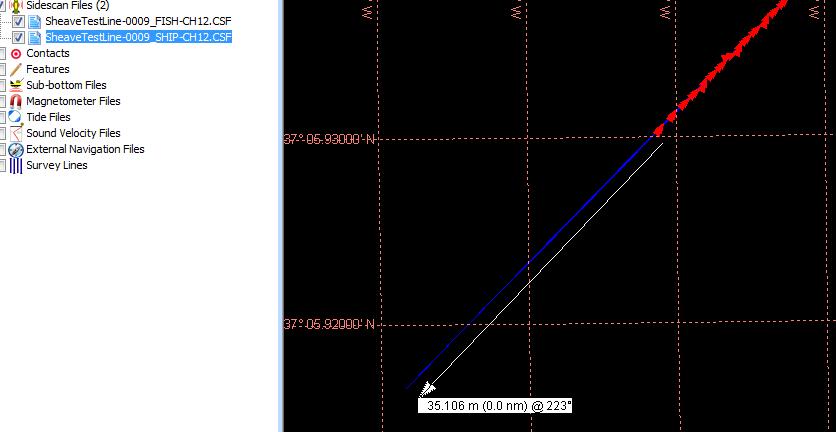
31 4.1.2 Test 1 - R/T Mosaic View The fish icon shows a lag behind the boat, and the distance is 50m. Next, the CMAX CM2 server started a simulated-data run and we did a quick record of 1 minute to create SheaveTest-0007.XTF. The file was renamed to SheaveTest- 0007_FISH.XTF and SheavTest-0007_SHIP.XTF, and two imports were done - using CONFIGURE EXISTING PROJECT before each import. The settings were: Rev 6, 4/30/2015 support@chesapeaktech.com Page 31

32 We imported the XTF line first using FISH navigation, Second, we imported the line using SHIP navigation. Rev 6, 4/30/ Page 32

33 Both project and import coordinate systems were set to UTM84-10N - Meters XTF Navigation Data View Using Tools -> Extract XTF Navigation, we can see that both fish and ship navigation got stored, and they are different. Rev 6, 4/30/2015 support@chesapeaktech.com Page 33

34 So sheave offset got added into the fish position. We'll import the file both ways and measure the position different, next: Rev 6, 4/30/ Page 34

35 4.1.4 Mosaic Plot of Fish line vs Ship line after IMPORT So the FISH-based navigation plot shows the line position back 50m, incorporating the SHEAVE OFFSET Fish line vs Ship line - Properties View The SHIP line PROPERTIES show that there are -50m sheave offset in the line: Rev 6, 4/30/2015 support@chesapeaktech.com Page 35


36 The FISH positioned line shows these properties: Rev 6, 4/30/ Page 36

37 4.2 Test 2 - Incorporating X=25 in Sheave Offset Note that sheave offset X=25 did displace the fish position in the R/T position view too: 4.3 Results Summary - Computed Sheave Offset and Cable Out effects We ran a set of tests and compiled the results in a table below. In each case below, we looked at the position of the sonar line in the mosaic view, with respect to each other, and looked at the reported PROPERTIES of each imported line. Test Condition Line Positions FISH vs SHIP PROPERTIES Test1 - sheave offset Y = -50 Fish lagged ship by 50 m Both lines show sheave offset Y= -50m Test2 - sheave offset Y= -50 Fish offset 50m back, 25m Both lines show sheave offset X = 25m southeast of ship Test3 - CableOut = 100m Fish lagged ship by only 35m, as if cable-out=100.0 was being interpreted as feet. Test4 - CableOut = 300m Test4 - sheave offset Y = - 50m CableOut = 300m Test5 - sheave offset Y = - 50m X = 25m CableOut = 100m Y= -50m, x = 25m CableOut = 100 shown for both lines Rev 6, 4/30/2015 support@chesapeaktech.com Page 37


38 More supporting evidence is shown below Test 2 - Imported FISH and SHIP lines - Mosaic Positions View Sheave offset Y = -50m, X = 25m in this case: Test 3 - Imported FISH and SHIP lines - Mosaic Positions View Set-up: Cable-out = 100m, no sheave offset. Rev 6, 4/30/2015 support@chesapeaktech.com Page 38


39 R/T view: Imported line positions: Rev 6, 4/30/ Page 39


40 Surprise - the offset was only 35m. Looks like 100 cable out was being interpreted as feet Test 4 - Imported FISH and SHIP lines - Mosaic Positions View Tried CableOut = 300m and the R/T view showed 300m: Imported lines: Rev 6, 4/30/2015 support@chesapeaktech.com Page 40

41 Rev 6, 4/30/ Page 41
PHY221 Lab 1 Discovering Motion: Introduction to Logger Pro and the Motion Detector; Motion with Constant Velocity
 PHY221 Lab 1 Discovering Motion: Introduction to Logger Pro and the Motion Detector; Motion with Constant Velocity Print Your Name Print Your Partners' Names Instructions August 31, 2016 Before lab, read
E X P E R I M E N T 1
 E X P E R I M E N T 1 Getting to Know Data Studio Produced by the Physics Staff at Collin College Copyright Collin College Physics Department. All Rights Reserved. University Physics, Exp 1: Getting to
Exercise #1: Create and Revise a Smart Group
 EndNote X7 Advanced: Hands-On for CDPH Sheldon Margen Public Health Library, UC Berkeley Exercise #1: Create and Revise a Smart Group Objective: Learn how to create and revise Smart Groups to automate
StrataSync. DSAM 24 Hour POP Report
 DSAM 24 Hour POP Report Thursday, January 28, 2016 Page 1 of 19 Table of Contents... 1... 1 Table of Contents... 2 Introduction... 3 POP Test Configuration Location File, Channel Plan, Limit Plan... 4
Using different reference quantities in ArtemiS SUITE
 06/17 in ArtemiS SUITE ArtemiS SUITE allows you to perform sound analyses versus a number of different reference quantities. Many analyses are calculated and displayed versus time, such as Level vs. Time,
4125 system setup and deployment quick start guide
 4125 system setup and deployment quick start guide OPERATION IN AIR Do not operate the system while the tow fish in air for extended periods. The system may be enabled to transmit while in air for test
Defining and Labeling Circuits and Electrical Phasing in PLS-CADD
 610 N. Whitney Way, Suite 160 Madison, WI 53705 Phone: 608.238.2171 Fax: 608.238.9241 Email:info@powline.com URL: http://www.powline.com Defining and Labeling Circuits and Electrical Phasing in PLS-CADD
DIFFERENTIATE SOMETHING AT THE VERY BEGINNING THE COURSE I'LL ADD YOU QUESTIONS USING THEM. BUT PARTICULAR QUESTIONS AS YOU'LL SEE
 1 MATH 16A LECTURE. OCTOBER 28, 2008. PROFESSOR: SO LET ME START WITH SOMETHING I'M SURE YOU ALL WANT TO HEAR ABOUT WHICH IS THE MIDTERM. THE NEXT MIDTERM. IT'S COMING UP, NOT THIS WEEK BUT THE NEXT WEEK.
ME EN 363 ELEMENTARY INSTRUMENTATION Lab: Basic Lab Instruments and Data Acquisition
 ME EN 363 ELEMENTARY INSTRUMENTATION Lab: Basic Lab Instruments and Data Acquisition INTRODUCTION Many sensors produce continuous voltage signals. In this lab, you will learn about some common methods
Application Note - TechComplete Test Productivity Pack. POP Reporting
 Application Note - TechComplete Test Productivity Pack Page 1 of 61 Table of Contents Introduction... 5 POP Test Configuration... 6 Executing POP Tests on DSAM... 7 Accessing POP Reports... 9 POP Reports
Source/Receiver (SR) Setup
 Setup") PS User Guide Series 2015 Source/Receiver (SR) Setup For 1-D and 2-D Vs Profiling Prepared By Choon B. Park, Ph.D. January 2015 Table of Contents Page 1. Overview 2 2. Source/Receiver (SR) Setup Main Menu
PS User Guide Series 2015 Source/Receiver (SR) Setup For 1-D and 2-D Vs Profiling Prepared By Choon B. Park, Ph.D. January 2015 Table of Contents Page 1. Overview 2 2. Source/Receiver (SR) Setup Main Menu
TL-2900 AMMONIA & NITRATE ANALYZER DUAL CHANNEL
 TL-2900 AMMONIA & NITRATE ANALYZER DUAL CHANNEL DATA ACQUISITION SYSTEM V.15.4 INSTRUCTION MANUAL Timberline Instruments, LLC 1880 S. Flatiron Ct., Unit I Boulder, Colorado 80301 Ph: (303) 440-8779 Fx:
GS122-2L. About the speakers:
 Dan Leighton DL Consulting Andrea Bell GS122-2L A growing number of utilities are adapting Autodesk Utility Design (AUD) as their primary design tool for electrical utilities. You will learn the basics
Getting Started with the LabVIEW Sound and Vibration Toolkit
 1 Getting Started with the LabVIEW Sound and Vibration Toolkit This tutorial is designed to introduce you to some of the sound and vibration analysis capabilities in the industry-leading software tool
Synergy SIS Attendance Administrator Guide
 Synergy SIS Attendance Administrator Guide Edupoint Educational Systems, LLC 1955 South Val Vista Road, Ste 210 Mesa, AZ 85204 Phone (877) 899-9111 Fax (800) 338-7646 Volume 01, Edition 01, Revision 04
PS User Guide Series Seismic-Data Display
 PS User Guide Series 2015 Seismic-Data Display Prepared By Choon B. Park, Ph.D. January 2015 Table of Contents Page 1. File 2 2. Data 2 2.1 Resample 3 3. Edit 4 3.1 Export Data 4 3.2 Cut/Append Records
APA Research Paper Chapter 2 Supplement
 Microsoft Office Word 00 Appendix D APA Research Paper Chapter Supplement Project Research Paper Based on APA Documentation Style As described in Chapter, two popular documentation styles for research
Data Acquisition Using LabVIEW
 Experiment-0 Data Acquisition Using LabVIEW Introduction The objectives of this experiment are to become acquainted with using computer-conrolled instrumentation for data acquisition. LabVIEW, a program
Linkage 3.6. User s Guide
 Linkage 3.6 User s Guide David Rector Friday, December 01, 2017 Table of Contents Table of Contents... 2 Release Notes (Recently New and Changed Stuff)... 3 Installation... 3 Running the Linkage Program...
TOMELLERI ENGINEERING MEASURING SYSTEMS. TUBO Version 7.2 Software Manual rev.0
 TOMELLERI ENGINEERING MEASURING SYSTEMS TUBO Version 7.2 Software Manual rev.0 Index 1. Overview... 3 2. Basic information... 4 2.1. Main window / Diagnosis... 5 2.2. Settings Window... 6 2.3. Serial transmission
For the SIA. Applications of Propagation Delay & Skew tool. Introduction. Theory of Operation. Propagation Delay & Skew Tool
 For the SIA Applications of Propagation Delay & Skew tool Determine signal propagation delay time Detect skewing between channels on rising or falling edges Create histograms of different edge relationships
SignalTap: An In-System Logic Analyzer
 SignalTap: An In-System Logic Analyzer I. Introduction In this chapter we will learn 1 how to use SignalTap II (SignalTap) (Altera Corporation 2010). This core is a logic analyzer provided by Altera that
Analyzing and Saving a Signal
 Analyzing and Saving a Signal Approximate Time You can complete this exercise in approximately 45 minutes. Background LabVIEW includes a set of Express VIs that help you analyze signals. This chapter teaches
Field Test 2. Installation and operation manual OPDAQ Installation and operation manual
 Field Test 2 Installation and operation manual OPDAQ 17.08.25 Installation and operation manual January 2016 How to get copies of OpDAQ technical publications: 53, St-Germain Ouest Rimouski, Québec Canada
Real-Time Spectrogram (RTS tm )
") Real-Time Spectrogram (RTS tm ) View, edit and measure digital sound files The Real-Time Spectrogram (RTS tm ) displays the time-aligned spectrogram and waveform of a continuous sound file. The RTS can
Real-Time Spectrogram (RTS tm ) View, edit and measure digital sound files The Real-Time Spectrogram (RTS tm ) displays the time-aligned spectrogram and waveform of a continuous sound file. The RTS can
SGG Knudsen 320 B/R Guide
 SGG Knudsen 320 B/R Guide The 320 B/R deepwater echosounder is configured for using two types of transducers mounted in the hull of the ship. The tranducers operate at two different frequencies. The frequencies
A-ATF (1) PictureGear Pocket. Operating Instructions Version 2.0
 PictureGear Pocket. Operating Instructions Version 2.0") A-ATF-200-11(1) PictureGear Pocket Operating Instructions Version 2.0 Introduction PictureGear Pocket What is PictureGear Pocket? What is PictureGear Pocket? PictureGear Pocket is a picture album application
A-ATF-200-11(1) PictureGear Pocket Operating Instructions Version 2.0 Introduction PictureGear Pocket What is PictureGear Pocket? What is PictureGear Pocket? PictureGear Pocket is a picture album application
(Skip to step 11 if you are already familiar with connecting to the Tribot)
") LEGO MINDSTORMS NXT Lab 5 Remember back in Lab 2 when the Tribot was commanded to drive in a specific pattern that had the shape of a bow tie? Specific commands were passed to the motors to command how
LEGO MINDSTORMS NXT Lab 5 Remember back in Lab 2 when the Tribot was commanded to drive in a specific pattern that had the shape of a bow tie? Specific commands were passed to the motors to command how
Physics 105. Spring Handbook of Instructions. M.J. Madsen Wabash College, Crawfordsville, Indiana
 Physics 105 Handbook of Instructions Spring 2010 M.J. Madsen Wabash College, Crawfordsville, Indiana 1 During the Middle Ages there were all kinds of crazy ideas, such as that a piece of rhinoceros horn
EDL8 Race Dash Manual Engine Management Systems
 Engine Management Systems EDL8 Race Dash Manual Engine Management Systems Page 1 EDL8 Race Dash Page 2 EMS Computers Pty Ltd Unit 9 / 171 Power St Glendenning NSW, 2761 Australia Phone.: +612 9675 1414
Topic: Instructional David G. Thomas December 23, 2015
 Procedure to Setup a 3ɸ Linear Motor This is a guide to configure a 3ɸ linear motor using either analog or digital encoder feedback with an Elmo Gold Line drive. Topic: Instructional David G. Thomas December
The Kaffeine Handbook. Jürgen Kofler Christophe Thommeret Mauro Carvalho Chehab
 Jürgen Kofler Christophe Thommeret Mauro Carvalho Chehab 2 Contents 1 Kaffeine Player 5 1.1 The Start Window...................................... 5 1.2 Play a File..........................................
with the Field-IQ Crop Input Control System
 with the Field-IQ Crop Input Control System Quick Reference Card CONNECTING THE SYSTEM Ag25 GNSS antenna (P/N 68040-OOS) TNC/TNC right-angle cable (P/N 50449) Cable assembly, display to Field-IQ (P/N 50449)
ASSEMBLY AND CALIBRATION
 CineMax Kit ASSEMBLY AND CALIBRATION www.cineversum.com Ref: T9003000 Rev: 01 Part. No.: R599766 Changes CineVERSUM provides this manual as is without warranty of any kind, either expressed or implied,
COPYRIGHT NOVEMBER-1998
 Application Notes: Interfacing AG-132 GPS with G-858 Magnetometer 25430-AM Rev.A Operation Manual COPYRIGHT NOVEMBER-1998 GEOMETRICS, INC. 2190 Fortune Drive, San Jose, Ca 95131 USA Phone: (408) 954-0522
What s New in Raven May 2006 This document briefly summarizes the new features that have been added to Raven since the release of Raven
 What s New in Raven 1.3 16 May 2006 This document briefly summarizes the new features that have been added to Raven since the release of Raven 1.2.1. Extensible multi-channel audio input device support
McIDAS-V Tutorial Using HYDRA to Interrogate Hyperspectral Data updated September 2015 (software version 1.5)
") McIDAS-V Tutorial Using HYDRA to Interrogate Hyperspectral Data updated September 2015 (software version 1.5) McIDAS-V is a free, open source, visualization and data analysis software package that is the
McIDAS-V Tutorial Using HYDRA to Interrogate Hyperspectral Data updated September 2015 (software version 1.5) McIDAS-V is a free, open source, visualization and data analysis software package that is the
Application Note AN-708 Vibration Measurements with the Vibration Synchronization Module
 Application Note AN-708 Vibration Measurements with the Vibration Synchronization Module Introduction The vibration module allows complete analysis of cyclical events using low-speed cameras. This is accomplished
Footnotes and Endnotes
 Footnotes and Endnotes Sometimes when writing a paper it is necessary to insert text at the bottom of a page in a document to reference something on that page. You do this by placing a footnote at the
NaviPac Cable Laying Utilities. Author : Ole Kristensen Company : EIVA a/s Date: April 2012
 NaviPac Cable Laying Utilities Author : Ole Kristensen Company : EIVA a/s Date: April 2012 NaviPac Cable laying Page 2 Introduction This document gives a short introduction to the catenary functions (for
MATH& 146 Lesson 11. Section 1.6 Categorical Data
 MATH& 146 Lesson 11 Section 1.6 Categorical Data 1 Frequency The first step to organizing categorical data is to count the number of data values there are in each category of interest. We can organize
Torsional vibration analysis in ArtemiS SUITE 1
 02/18 in ArtemiS SUITE 1 Introduction 1 Revolution speed information as a separate analog channel 1 Revolution speed information as a digital pulse channel 2 Proceeding and general notes 3 Application
SEM- EDS Instruction Manual
 SEM- EDS Instruction Manual Double-click on the Spirit icon ( ) on the desktop to start the software program. I. X-ray Functions Access the basic X-ray acquisition, display and analysis functions through
Chapter 40: MIDI Tool
 MIDI Tool 40-1 40: MIDI Tool MIDI Tool What it does This tool lets you edit the actual MIDI data that Finale stores with your music key velocities (how hard each note was struck), Start and Stop Times
Cisco Spectrum Expert Software Overview
 CHAPTER 5 If your computer has an 802.11 interface, it should be enabled in order to detect Wi-Fi devices. If you are connected to an AP or ad-hoc network through the 802.11 interface, you will occasionally
X-Sign 2.0 User Manual
 X-Sign 2.0 User Manual Copyright Copyright 2018 by BenQ Corporation. All rights reserved. No part of this publication may be reproduced, transmitted, transcribed, stored in a retrieval system or translated
Getting started with CitNetExplorer version 1.0.0
 Getting started with CitNetExplorer version 1.0.0 Nees Jan van Eck and Ludo Waltman Centre for Science and Technology Studies (CWTS), Leiden University March 10, 2014 CitNetExplorer is a software tool
Tutorial 3 Normalize step-cycles, average waveform amplitude and the Layout program
 Tutorial 3 Normalize step-cycles, average waveform amplitude and the Layout program Step cycles are defined usually by choosing a recorded ENG waveform that shows long lasting, continuos, consistently
MODFLOW - Grid Approach
 GMS 7.0 TUTORIALS MODFLOW - Grid Approach 1 Introduction Two approaches can be used to construct a MODFLOW simulation in GMS: the grid approach and the conceptual model approach. The grid approach involves
LAX_x Logic Analyzer
 Legacy documentation LAX_x Logic Analyzer Summary This core reference describes how to place and use a Logic Analyzer instrument in an FPGA design. Core Reference CR0103 (v2.0) March 17, 2008 The LAX_x
Software Quick Manual
 XX177-24-00 Virtual Matrix Display Controller Quick Manual Vicon Industries Inc. does not warrant that the functions contained in this equipment will meet your requirements or that the operation will be
DCD-24 Word Clock Distributor
 DCD-24 Word Clock Distributor Owner s manual Version 1.00 October 2018 All materials herein Brainstorm Electronics, Inc. Brainstorm Electronics reserves the right to change or modify the contents of this
Quick Reference Manual
 Quick Reference Manual V1.0 1 Contents 1.0 PRODUCT INTRODUCTION...3 2.0 SYSTEM REQUIREMENTS...5 3.0 INSTALLING PDF-D FLEXRAY PROTOCOL ANALYSIS SOFTWARE...5 4.0 CONNECTING TO AN OSCILLOSCOPE...6 5.0 CONFIGURE
Lab experience 1: Introduction to LabView
 Lab experience 1: Introduction to LabView LabView is software for the real-time acquisition, processing and visualization of measured data. A LabView program is called a Virtual Instrument (VI) because
User's Guide. Version 2.3 July 10, VTelevision User's Guide. Page 1
 User's Guide Version 2.3 July 10, 2013 Page 1 Contents VTelevision User s Guide...5 Using the End User s Guide... 6 Watching TV with VTelevision... 7 Turning on Your TV and VTelevision... 7 Using the Set-Top
Pole Zero Correction using OBSPY and PSN Data
 Pole Zero Correction using OBSPY and PSN Data Obspy provides the possibility of instrument response correction. WinSDR and WinQuake already have capability to embed the required information into the event
USER MANUAL FOR DDT 2D. Introduction. Installation. Getting Started. Danley Design Tool 2d. Welcome to the Danley Design Tool 2D program.
 USER MANUAL FOR DDT 2D ( VERSION 1.8) Welcome to the Danley Design Tool 2D program. Introduction DDT2D is a very powerful tool that lets the user visualize how sound propagates from loudspeakers, including
EYE TRACKING DATA ANALYSIS TOOL
 ETAnalysis Manual EYE TRACKING DATA ANALYSIS TOOL MANUAL VERSION 1.1 May, 2017 Argus Science LLC Email: argus@argusscience.com Table of Contents 1 INTRODUCTION... 5 1.1 BASIC FEATURES... 5 1.2 OPTIONAL
Table of content. Table of content Introduction Concepts Hardware setup...4
 Table of content Table of content... 1 Introduction... 2 1. Concepts...3 2. Hardware setup...4 2.1. ArtNet, Nodes and Switches...4 2.2. e:cue butlers...5 2.3. Computer...5 3. Installation...6 4. LED Mapper
Dektak Step by Step Instructions:
 Dektak Step by Step Instructions: Before Using the Equipment SIGN IN THE LOG BOOK Part 1: Setup 1. Turn on the switch at the back of the dektak machine. Then start up the computer. 2. Place the sample
Silver Mountain Targets V2 Software Reference Guide. July 22, 2015
 Silver Mountain Targets V2 Software Reference Guide July 22, 2015 1. Setting up new targets for the first time If this is the first time using the e-targets on a target frame, you will need to create and
Table of Contents. 2 Select camera-lens configuration Select camera and lens type Listbox: Select source image... 8
 Table of Contents 1 Starting the program 3 1.1 Installation of the program.......................... 3 1.2 Starting the program.............................. 3 1.3 Control button: Load source image......................
APPLICATION NOTE AN-B03. Aug 30, Bobcat CAMERA SERIES CREATING LOOK-UP-TABLES
 APPLICATION NOTE AN-B03 Aug 30, 2013 Bobcat CAMERA SERIES CREATING LOOK-UP-TABLES Abstract: This application note describes how to create and use look-uptables. This note applies to both CameraLink and
VeriLUM 5.2. Video Display Calibration And Conformance Tracking. IMAGE Smiths, Inc. P.O. Box 30928, Bethesda, MD USA
 VeriLUM 5.2 Video Display Calibration And Conformance Tracking IMAGE Smiths, Inc. P.O. Box 30928, Bethesda, MD 20824 USA Voice: 240-395-1600 Fax: 240-395-1601 Web: www.image-smiths.com Technical Support
PLEN Motion Editor Operation Procedures Temporary File
 1 PLEN Motion Editor Operation Procedures Temporary File 2 Table of Contents I. Introduction 3 1. Overview of MotionEditor 3 2. Operating Environment. 3 3. Installing the MotionEditor... 3 4. PLEN's Preparation
Agilent DSO5014A Oscilloscope Tutorial
 Contents UNIVERSITY OF CALIFORNIA AT BERKELEY College of Engineering Department of Electrical Engineering and Computer Sciences EE105 Lab Experiments Agilent DSO5014A Oscilloscope Tutorial 1 Introduction
MultiSpec Tutorial: Visualizing Growing Degree Day (GDD) Images. In this tutorial, the MultiSpec image processing software will be used to:
 Images. In this tutorial, the MultiSpec image processing software will be used to:") MultiSpec Tutorial: Background: This tutorial illustrates how MultiSpec can me used for handling and analysis of general geospatial images. The image data used in this example is not multispectral data
MultiSpec Tutorial: Background: This tutorial illustrates how MultiSpec can me used for handling and analysis of general geospatial images. The image data used in this example is not multispectral data
#PS168 - Analysis of Intraventricular Pressure Wave Data (LVP Analysis)
") BIOPAC Systems, Inc. 42 Aero Camino Goleta, Ca 93117 Ph (805)685-0066 Fax (805)685-0067 www.biopac.com info@biopac.com #PS168 - Analysis of Intraventricular Pressure Wave Data (LVP Analysis) The Biopac
BIOPAC Systems, Inc. 42 Aero Camino Goleta, Ca 93117 Ph (805)685-0066 Fax (805)685-0067 www.biopac.com info@biopac.com #PS168 - Analysis of Intraventricular Pressure Wave Data (LVP Analysis) The Biopac
AmbDec User Manual. Fons Adriaensen
 AmbDec - 0.4.2 User Manual Fons Adriaensen fons@kokkinizita.net Contents 1 Introduction 3 1.1 Computing decoder matrices............................. 3 2 Installing and running AmbDec 4 2.1 Installing
Wireless Studio. User s Guide Version 5.1x Before using this software, please read this manual thoroughly and retain it for future reference.
 4-743-161-12 (1) Wireless Studio User s Guide Version 5.1x Before using this software, please read this manual thoroughly and retain it for future reference. DWR-R01D/R02D/R02DN/R03D 2018 Sony Corporation
Processes for the Intersection
 7 Timing Processes for the Intersection In Chapter 6, you studied the operation of one intersection approach and determined the value of the vehicle extension time that would extend the green for as long
KRAMER ELECTRONICS LTD. USER MANUAL
 KRAMER ELECTRONICS LTD. USER MANUAL MODEL: Projection Curved Screen Blend Guide How to blend projection images on a curved screen using the Warp Generator version K-1.4 Introduction The guide describes
isync HD & isync Pro Quick Reference Guide isync HD isync Pro Digital Video Processor and Video/Audio Switcher
 isync HD & isync Pro Digital Video Processor and Video/Audio Switcher Quick Reference Guide isync HD Key Digital, led by digital video pioneer Mike Tsinberg, develops and manufactures high quality, cutting-edge
Electrical and Electronic Laboratory Faculty of Engineering Chulalongkorn University. Cathode-Ray Oscilloscope (CRO)
") 2141274 Electrical and Electronic Laboratory Faculty of Engineering Chulalongkorn University Cathode-Ray Oscilloscope (CRO) Objectives You will be able to use an oscilloscope to measure voltage, frequency
2141274 Electrical and Electronic Laboratory Faculty of Engineering Chulalongkorn University Cathode-Ray Oscilloscope (CRO) Objectives You will be able to use an oscilloscope to measure voltage, frequency
Using Spectrum Laboratory (Spec Lab) for Precise Audio Frequency Measurements
 for Precise Audio Frequency Measurements") Using Spectrum Laboratory (Spec Lab) for Precise Audio Frequency Measurements Ver 1.15 Nov 2009 Jacques Audet VE2AZX ve2azx@amsat.org WEB: ve2azx.net NOTE: SpecLab version V2.7 b18 has some problems with
Using Spectrum Laboratory (Spec Lab) for Precise Audio Frequency Measurements Ver 1.15 Nov 2009 Jacques Audet VE2AZX ve2azx@amsat.org WEB: ve2azx.net NOTE: SpecLab version V2.7 b18 has some problems with
SIDRA INTERSECTION 8.0 UPDATE HISTORY
 Akcelik & Associates Pty Ltd PO Box 1075G, Greythorn, Vic 3104 AUSTRALIA ABN 79 088 889 687 For all technical support, sales support and general enquiries: support.sidrasolutions.com SIDRA INTERSECTION
Modbus for SKF IMx and Analyst
 User manual Modbus for SKF IMx and SKF @ptitude Analyst Part No. 32342700-EN Revision A WARNING! - Read this manual before using this product. Failure to follow the instructions and safety precautions
EAN-Performance and Latency
 EAN-Performance and Latency PN: EAN-Performance-and-Latency 6/4/2018 SightLine Applications, Inc. Contact: Web: sightlineapplications.com Sales: sales@sightlineapplications.com Support: support@sightlineapplications.com
FSI Calibration Guide Using CR100 / LightSpace / BoxIO
 FSI Calibration Guide Using CR100 / LightSpace / BoxIO Flanders Scientific, Inc. 6215 Shiloh Crossing Suite G Alpharetta, GA 30005 Phone: +1.678.835.4934 Fax: +1.678.804.1882 E-Mail: Support@FlandersScientific.com
7thSense Design Delta Media Server
 7thSense Design Delta Media Server Channel Alignment Guide: Warping and Blending Original by Andy B Adapted by Helen W (November 2015) 1 Trademark Information Delta, Delta Media Server, Delta Nano, Delta
PicoScope 6 Training Manual
 PicoScope 6 Training Manual DO226 PicoScope 6 Training Manual r2.docx Copyright 2014 Pico Technology CONTENTS 1 Quick guide to PicoScope 6... 1 1.1 The PicoScope way... 1 1.2 Signal view... 2 1.3 Timebase...
PulseCounter Neutron & Gamma Spectrometry Software Manual
 PulseCounter Neutron & Gamma Spectrometry Software Manual MAXIMUS ENERGY CORPORATION Written by Dr. Max I. Fomitchev-Zamilov Web: maximus.energy TABLE OF CONTENTS 0. GENERAL INFORMATION 1. DEFAULT SCREEN
What to look for when choosing an oscilloscope
 What to look for when choosing an oscilloscope Alan Tong (Pico Technology Ltd.) Introduction For many engineers, choosing a new oscilloscope can be daunting there are hundreds of different models to choose
CARLO GAVAZZI Automation Components
 CARLO GAVAZZI Automation Components UDM 35/40 Digital Panel Meter Programming Guide Index Description 2 Programming Fundamentals 3 Access to Programming Mode/Password Protection 4 Programming 5-18 Inputs
v. 8.0 GMS 8.0 Tutorial MODFLOW Grid Approach Build a MODFLOW model on a 3D grid Prerequisite Tutorials None Time minutes
 v. 8.0 GMS 8.0 Tutorial Build a MODFLOW model on a 3D grid Objectives The grid approach to MODFLOW pre-processing is described in this tutorial. In most cases, the conceptual model approach is more powerful
Introduction to EndNote Online
 Introduction to EndNote Online Creating an EndNote Online account Go to EndNote Online. Click on the Access EndNote Online button and, if prompted, enter your Warwick username and password to confirm you
DXD-8 Universal Clock
 DXD-8 Universal Clock Owner s manual Version 1.00 October 2018 All materials herein Brainstorm Electronics, Inc. Brainstorm Electronics reserves the right to change or modify the contents of this manual
Altera s Max+plus II Tutorial
 Altera s Max+plus II Tutorial Written by Kris Schindler To accompany Digital Principles and Design (by Donald D. Givone) 8/30/02 1 About Max+plus II Altera s Max+plus II is a powerful simulation package
Neue ELSA GmbH Sonnenweg Aachen Germany
 2002 Neue ELSA GmbH, Aachen (Germany) While the information in this manual has been compiled with great care, it may not be deemed an assurance of product characteristics. Neue ELSA GmbH shall be liable
ELSA WINNER Series M a n u a l
 Manual Series 2002 Neue ELSA GmbH, Aachen (Germany) While the information in this manual has been compiled with great care, it may not be deemed an assurance of product characteristics. Neue ELSA GmbH
Survey on Electronic Book Features
 Survey on Electronic Book Features Written by Harold Henke Sponsored by the Open ebook Forum Published March 20, 2002 Visit the OeBF at: www.openebook.org Copyright 2002, Open ebook Forum Survey, copyright
PCIe: EYE DIAGRAM ANALYSIS IN HYPERLYNX
 PCIe: EYE DIAGRAM ANALYSIS IN HYPERLYNX w w w. m e n t o r. c o m PCIe: Eye Diagram Analysis in HyperLynx PCI Express Tutorial This PCI Express tutorial will walk you through time-domain eye diagram analysis
De-embedding Gigaprobes Using Time Domain Gating with the LeCroy SPARQ
 De-embedding Gigaprobes Using Time Domain Gating with the LeCroy SPARQ Dr. Alan Blankman, Product Manager Summary Differential S-parameters can be measured using the Gigaprobe DVT30-1mm differential TDR
MestReNova Manual for Chem 201/202. October, 2015.
 1. Introduction to 1-D NMR Data Processing with MestReNova The MestReNova program can do all of the routine NMR data processing needed for Chem 201 and 202 and will be available through the Reed downloads
Transient Stability Events & Actions
 ETAP TIP No. 009 Transient Stability Events & Actions Applicable ETAP Versions: 5.5.0, 5.5.5, 5.5.6 (For lower versions, some of the descriptions and procedures below may differ in some ways) Event is
The DataView PowerPad III Control Panel
 Setting Up a Recording Session in the DataView PowerPad III Control Panel By Mike Van Dunk The DataView PowerPad III Control Panel is designed for working with AEMC PowerPad III Power Quality Analyzers,
A Matlab toolbox for. Characterisation Of Recorded Underwater Sound (CHORUS) USER S GUIDE
 USER S GUIDE") Centre for Marine Science and Technology A Matlab toolbox for Characterisation Of Recorded Underwater Sound (CHORUS) USER S GUIDE Version 5.0b Prepared for: Centre for Marine Science and Technology Prepared
Centre for Marine Science and Technology A Matlab toolbox for Characterisation Of Recorded Underwater Sound (CHORUS) USER S GUIDE Version 5.0b Prepared for: Centre for Marine Science and Technology Prepared
Tutorial 11 ChipscopePro, ISE 10.1 and Xilinx Simulator on the Digilent Spartan-3E board
 Tutorial 11 ChipscopePro, ISE 10.1 and Xilinx Simulator on the Digilent Spartan-3E board Introduction This lab will be an introduction on how to use ChipScope for the verification of the designs done on
Remote Application Update for the RCM33xx
 Remote Application Update for the RCM33xx AN418 The common method of remotely updating an embedded application is to write directly to parallel flash. This is a potentially dangerous operation because
Event recording (or logging) with a Fluke 287/289 Digital Multimeter
 with a Fluke 287/289 Digital Multimeter") Event recording (or logging) with a Fluke 287/289 Digital Multimeter Application Note One of the major features of the Fluke 280 Series digital multimeters (DMM) with TrendCapture is their ability to record
Event recording (or logging) with a Fluke 287/289 Digital Multimeter Application Note One of the major features of the Fluke 280 Series digital multimeters (DMM) with TrendCapture is their ability to record