Vein-Eye. Vein Illumination System USER MANUAL. Vein-Eye Hospital Cart (HC) and Attached Unit (AU)
|
|
|
- Cody Adams
- 5 years ago
- Views:
Transcription
 U.S. Patent number 5,929,443 Document No.")
1 Vein Illumination System Vein-Eye Hospital Cart (HC) and Attached Unit (AU) Near Infrared Imaging, Inc. Customer Service ( Service: 24/7 365) U.S. Patent number 5,929,443 Document No.:
2 2 Table of Contents Venipuncture 4 Venipuncture: easy and accurate 4 Vein-Eye product configurations 5 Vein-Eye models 5 Vein-Eye AU (Attached Unit) overview 6 Camera & monitor 6 Adjusting the image on the AU monitor 6 Alignment of the camera before imaging 7 Vein-Eye HC (Hospital Cart) overview 7 Basket on the Vein-Eye HC 7 Small and balanced cart base 8 Getting started with the HC 8 How to lock the Vein-Eye HC 8 Moving the Vein-Eye HC (Transportation) 9 Turning the Vein-Eye OFF And ON 10 Connecting the Vein-Eye system components 10 System specifications (BOM) 11 System parameters 11 Recommendations for proper use 12 Operator qualifications 12 Operator training 12 General cautions & warnings 12 WARNINGS 14 WARNINGS 14 Avoiding Potential Electromagnetic Or Other Interferences 15
3 3 Guidance And Manufacturer s Declaration - Electromagnetic Emissions & Immunity 16 Guidance and Manufacturer s Declaration - Electromagnetic Emissions 16 Recommended separation distances between portable and mobile RF communications equipment and the Vein-Eye System 16 Guidance and Manufacturer's Declaration - Electromagnetic Immunity 17 Guidance and Manufacturer's Declaration - Electromagnetic Immunity 18 Vein-Eye Operating Temperature 19 Maintenance Of Vein-Eye Illumination System 19 Service 19 Cleaning and Disinfecting 19 Storage 20 Physical Shock 20 Inspection 20 Disposal Instructions 20 Limited Warranty 20 Customer Service 21 On Screen Display (OSD) Settings 22-25


4 4 Venipuncture Drawing blood or starting an IV can be a very challenging task, even for the skilled medical professional. The Vein-Eye makes this task easier. While some medical practitioners may not require an image guidance system for the majority of vein punctures, the Vein-Eye is designed for first attempt success even with the more challenging vein punctures. And, there will always be the rare occasion when the room environment, or the biology of the patient, provides a challenge even with the Vein-Eye. The patented technology of the Vein-Eye provides real-time video of subdermal veins located on various parts of the body, particularly the patient's arm or hand. The video displays a runway image of the patient s vein, necessary for IV placements. Venipuncture: Easy And Accurate The Vein-Eye s imaging capability reduces the number of unsuccessful attempts and improves patient well-being. The Vein-Eye provides direct imaging of the entire area of interest with operator adjustable magnification. The image is displayed on a high resolution monitor and can be used throughout the entire procedure
5 5 Vein-Eye Product Configurations The Vein-Eye vein Illumination System includes a camera, monitor, power adapter, C-clamp mount bracket (Attached Unit) or wheeled mobile stand (Hospital Cart) Configuration AU HC # Item Description Model Model Camera on 1 Gooseneck Tube Power adapter with 2 power splitter 3 Monitor assembly Camera 700 TVL 12V 1A (Sony Sensor, 6~22mm Varifocal Lens, LED, optical filter, OSD cable, gooseneck tube ) X X Power Adapter for wall outlet power source input: V AC~50/60Hz 0.8-4A X X output: 12V DC---2A, Power splitter 8" Monitor 12V DC 0.5A (800x600 resolution) with monitor mount clamp X X 4 C-clamp assembly C-clamp and bracket for AU model X Cart stand with O-ring or bike mount bracket and basket for 5 Cart Stand assembly X HC model The electrical rating for the Vein-Eye System - Model Vein-Eye AU - Model Vein-Eye HC 12V DC 1.9A MAX. 22.8W Vein-Eye Models There are no contra-indications in the Vein-Eye.


6 6 Vein-Eye AU (Attached Unit) Model Overview The AU can be installed on fixed locations such as a desk, phlebotomy chair, table, etc The all-in-one design allows for access in tight spaces The design allows for hands-free operation A storage basket is attached to the clamp and located at the side of a chair, bed or a desktop. This allows for an organized and compact area of operation. Connect C-clamp and basket to gooseneck tube to operate Camera & Monitor Easy viewing of the images on the monitor: no interference with visual examination Position of camera is adjustable by means of a sturdy and flexible gooseneck tube, pole and cart base Monitor can tilt and swivel for easy viewing Adjusting The Camera and Monitor After completion of the assembly of the Vein-Eye AU system, on either a desk top or the arm of the chair, it is the time to set up the camera. Insert the plug of the power adapter into the wall power source. The On screen settings have been preset for the best results. Make certain that there is a white sheet or piece of paper underneath the patient s arm or hand and there is no sunlight in the immediate area. Do not change the settings unless absolutely necessary, and wait until a technician is working with you.

 facing the surface nearly vertically (both the HC")
 Model Overview Hands-free operation Lightweight, easily fits into a closet or corner Adjustable 8 high-resolution monitor attached to")

7 7 Adjust the monitor to the appropriate position for the optimal viewing. With the patient sitting in front of you, position their arm on the table or chair. The optimal distance from the arm or hand to the Vein-Eye is 12 to 18 The gooseneck and camera must be handled gently and using minimal force for positioning When aiming the camera at the target, use the Zoom knob to obtain the right size image. Use the Focus knob to obtain the clearest image. Alignment Of The Camera Before Imaging The camera must be placed above the area of interest (such as the arm) facing the surface nearly vertically (both the HC and AU). Arrange the patient s arm or hand along the circle (as shown in the picture) in order to obtain the optimal viewing areas of the arm and hand. Vein-Eye HC (Hospital Cart) Model Overview Hands-free operation Lightweight, easily fits into a closet or corner Adjustable 8 high-resolution monitor attached to the gooseneck for easy viewing. A basket to carry hosting cables and wires 5 wheels for easy portability Sturdy locking-in-place procedure for the wheels Basket On Vein-Eye HC The basket is attached to the pole of the cart stand and should be used ONLY for the storage of the power adapter and cables. The basket can also be used as a handle when transporting the HC.


8 8 Small And Balanced Cart Base Compact size: small diameter of the base for flexible positioning and movement in small or crowded spaces. 5 legs to balance the cart in all directions 5 wheels able to be locked firmly in position Getting Started With HC Model Follow the Assembly Manual to correctly connect the camera, gooseneck tube, monitor, and cart stand. The procedure is the same for both the AU and HC. How To Lock The Vein-Eye HC It is very important to lock the Vein-Eye HC in a firm location before servicing the patient. Please simply hold the gooseneck and use your foot to press down on the locking mechanism of the wheel.

 transport.")

9 9 Moving Vein-Eye HC (Transportation) (Figure 1) Hold the basket at your side and behind you (Figure 2) Pull the HC behind you when are walking to your destination The Vein-Eye HC is equipped with wheeled casters to enable free rolling and turning. Before moving the HC, please bend the gooseneck tube so that the camera is tucked into the stand as close as possible. The height of the adjustable pole shall not be extended more than 5 cm, or 2 inches, from the opening of its hosting pipe. This is shown in Figure 3 and allows for better stability in (Figure 3) transport. Hold firmly the Vein-Eye basket, which is attached to the middle of the pole of the Vein-Eye HC, as shown in figure 1. The Vein-Eye HC should be positioned on either side of the user, and slightly behind the user. Pulling the Vein-Eye HC, walk toward your way to destination as shown in figure 2. Avoid holding the camera or gooseneck in transport. There is the chance for tipping when transporting the HC on a floor with an inclination greater than 5 degrees. The Vein-Eye HC has to be held securely so that it will not tilt. The Vein-Eye camera should be tucked into the stand as close as possible.


10 10 Turning The Vein-Eye OFF And ON Turning the Vein-Eye OFF or ON is accomplished by simply plugging in and unplugging the power adapter from the source of electricity. It is recommended to turn the Vein-Eye OFF when not in use. Connecting The Vein-Eye System Components (Electric Circuit Diagram)
11 11 System Specifications (BOM) # Item Description Manufacturer Model AU HC Model Model Camera 700 TVL 12V DC 1A (Sony Camera on Sensor, 6~22mm Varifocal Lens) Neon Y Y 1 Gooseneck with LED, optical filter, OSD NCB-IS6E338IOH-NTSC Tube cable, gooseneck tube Or equivalent Power Power JS Technology 12V 2.0A Power Adapter, Power 2 adapter with MPU30A-3 splitter power splitter Or equivalent Y Y 8" Monitor 12V DC 0.5A Towin L8009 Monitor with 3 (800x600 resolution) with Or equivalent mount clamp monitor clamp and Adapters Y Y Sparqtron Y C-clamp with C-clamp with basket for AU 4 CC-BK-1 basket model Or equivalent Cart Stand 5 with O-ring and baskets Cart stand with O-ring or bike mount bracket, baskets for HC model Sparqtron CS-OB-1 Or equivalent Y Note: NII reserves the right to change the specifications of the product without notice. Users should visit NII s website at for new product updates. System Parameters Height: HC Model Maximum- 62", Minimum- 54.6" AU Model 34" Weight: HC Model 19 lb AU Model 7.5 lb Wide: HC Model Diameter- 18.5" (Caster Base) Operating Temperature 3.9 C to 40.5 C (39.02 F to F) Humidity 5.1% to 86% RH non-condensing Transport Temperature C to 51 C (-3.1 F to F) Humidity 4.9% to 86% RH non-condensing Storage Temperature -21 C to 51 C (-5.8 F to F) Humidity 4.9% to 86% RH non-condensing
12 12 Recommendations For Proper Use The camera and monitor are configured at the factory. The end user should not adjust the fixed internal camera and monitor settings. If there is a need to adjust the internal settings of the camera or monitor, contact your system administrator or distributor. If the images are not clear and crisp, there may be factors in the environment causing this. Do not attempt to use the Vein-Eye when the camera or patient is in direct sunlight. The camera should be held approximately 12 inches to 18 inches from the patient. The user or patient should avoid direct eye exposure from close proximity. The camera is equipped with LEDs that produce near infrared light that is invisible to the eye. Pulling or pushing the Vein-Eye H/C improperly could result in tipping. Operator Qualifications The healthcare professional operating the Vein-Eye Illumination System must have a general knowledge of peripheral veins and vein puncturing medical procedures. The healthcare professional must understand the basic operating principles of the Vein-Eye before attempting to use. Operator Training This Vein-Eye Illumination system is intended to be used by healthcare professionals only. This User Manual is for the Vein-Eye Illumination System. Prior to using the device, become familiar with the operating instructions in this User Manual. The Vein-Eye Illumination System is a unique concept, as it allows the user to image, in real-time video, peripheral veins to be used in medical procedures, such as vein punctures. Prior to patient evaluation, inspect the Vein-Eye Illumination System for any physical damage, such as a cracked or broken camera, monitor, cables, stand, clamp, power adapter, etc If physical damage exists, do not use and contact your local Distributor for service. General Cautions & Warnings Before use of the product, read the General Caution & Warnings and the Specific Cautions & Warnings pertaining to the Vein-Eye Illumination system. If you need further assistance, see the Service section of this manual. This manual applies to the following Near Infrared Imaging product model numbers and versions: Vein-Eye Vein Illumination System (AU and HC models)


13 13 Attention Consult Accompanying Documents CE Mark Indicates this device is in compliance with MDD 93/42/ECC. REF Catalogue or Model Number S/N Serial Number Manufacturer Manufacture Date Authorized representative in the European community. Keep Dry Directive Logo. The return of the Vein-Eye, for proper disposal, is encouraged. Please return to your distributor. Pay attention to the floor when transporting or when on an inclination Indoor Use Only General warning sign If the ETL Listed mark has a US to the bottom right, it has passed U.S. product safety standards. If it has a C to the bottom left, it has passed Canadian product safety standards. If the ETL mark displays both identifiers, it meets both standards.

14 14 Symbol for prescription only. U.S. federal law restricts this device to sale by or on the order of a physician or properly licensed practitioner. Symbol to instruct the user and/or operator to bend in the flexible gooseneck with the camera attached as close as possible to the pole when the Vein-Eye is in transport from one location to another. Please follow the instruction in the Moving Vein-Eye HC (Transportation) section. WARNINGS All Near Infrared Imaging s products are intended for use by healthcare professional. Read all instructions for use (User Manual, Assembly Guide) and specifications provided prior to use. Use extreme caution when moving and storing the View-Eye Illumination system to prevent the unit from tipping over. When transporting the Vein-Eye HC on a floor that has an inclination greater than 5 degrees, the Vein-Eye HC must be held securely so that it will not tip over. The Vein-Eye HC can be held securely by placing a hand on the attached basket or on the pole/stand. The Camera should be tucked into the stand as close as possible. Do not use this product without first reading and understanding the instructions contained in this booklet. If you are unable to understand the Warnings, Cautions or Instructions, contact a healthcare professional, dealer or technical personnel before use. Serious bodily injury or product damage may occur if the Warnings, Cautions or Instructions are not adhered to. Do not exceed the maximum weight of three (3) lbs. in the basket All wheels must be in contact with the floor at all times. WARNINGS When moving Vein-Eye HC, avoid wet or slick surfaces, wires, cables, or tubes and any uneven surfaces that may cause the system to tip or overturn. Only use accessories and spare parts authorized by Near Infrared Imaging. Do not attach the Vein-Eye HC to other objects. Do not use the Vein-Eye HC for support or as a walking aid. Do not attempt to use the Vein-Eye to support your weight, or use as an assist, while standing. The Vein-Eye Illumination system is for external use only. Do not immerse in water.
15 15 Do not drop. Only the AC adaptor and cable should be placed in the basket. Do not disassemble the Vein-Eye HC once it is assembled. Do not attempt to disconnect the camera from the gooseneck. Use extreme caution when moving the Vein-Eye HC to avoid contact with walls, doors, or other fixed structures. Use extreme caution when moving the Vein-Eye so that the camera does not come in contact with patients or other personnel. When transporting, do not allow the AC adapter or cables to bump into other objects, doors, or other equipment. Wheels should be locked in place when using the Vein-Eye HC Do not use the Vein-Eye in the presence of flammable anesthetic mixture. Use of accessory equipment not complying with EN and/or UL or equivalent safety standard may lead to a reduced level of safety of the resulting system. No modification of this product is allowed Do not modify this equipment without authorization of the manufacturer. If this equipment is modified, appropriate inspection and testing must be conducted to ensure continued safe use of the equipment. Do not allow sharp objects to touch device or cord(s)/ cable(s), as they may cause damage. If the Vein-Eye Illumination System is used with other devices, electrical current leakage may increase and electric shock may be caused. It is the user s responsibility to ensure safety when the device is used with other medical equipment. If safety cannot be ensured, use of the Vein-Eye Illumination System with other devices is not allowed. Do not use a power adapter with specifications different from what is listed in this manual. Cautions: Federal (USA) law requires the order of a physician in order for the Vein-Eye to be sold and used by a healthcare professional in the USA. For Near Infrared Imaging s products marked with company for proper disposal instructions., please contact your local Distributor or your local waste Avoiding Potential Electromagnetic Or Other Interferences The power supply for the Vein-Eye is grounded and will limit EMI charges around the device. There is also shielding for the camera which is designed to limit any EMI interference to the camera and signals. The monitor is also designed to have limited EMI interference and is grounded, as is the power supply, to limit exposure to EMI. The Vein-Eye should have no electromagnetic interference (EMI) from other devices. In case a user discovers an EMI impact to Vein-Eye System, the user should avoid the possible cause of electromagnetic interference from other devices.
16 16 There are adjustments that can be made to avoid or reduce EMI that is affecting the Vein-Eye System: 1) Physical Isolation: Keep devices that emit electromagnetic radiation away from the Vein-Eye, such as electronics devices or electronic medical devices. 2) Use of Dedicated Circuits: Keep the Vein-Eye on a circuit that is separate from the circuit running other electronic devices. This will result in a significant reduction of interference passing to the Vein-Eye from the other devices. 3) Power Conditioning: The use of a line conditioner, or uninterruptible power supply, can filter out interference caused by other devices that share a line with the Vein-Eye. Guidance And Manufacturer s Declaration - Electromagnetic Emissions & Immunity Medical electrical equipment requires certain precautions regarding EMC and medical electrical equipment needs to be installed and put into service according to EMC information provided in this document. Guidance and Manufacturer s Declaration - Electromagnetic Emissions The Vein-Eye System is intended for use in the electromagnetic environment specified below. The customer or the user of the Vein-Eye System should assure that it is used in such an environment. Emissions Test Compliance Electromagnetic Environment Guidance The Vein-Eye System uses RF energy only for its internal function. RF Emissions CISPR 11 Group 1 Therefore, its RF emissions are very low and are not likely to cause any interference to nearby electronics. RF Emissions CISPR 11 Class A Harmonic Emissions IEC Complies Voltage Fluctuations IEC Complies The Vein-Eye System is suitable for use in all establishments other than (1) domestic and (2) those buildings that are used for domestic and are directly connected to any public low-voltage power source. Recommended separation distances between portable and mobile RF communications equipment and the Vein-Eye System The Vein-Eye System is intended for use in an electromagnetic environment in which radiated RF disturbances are controlled. The user of the Vein-Eye System can help prevent electromagnetic interference by maintaining a minimum distance between portable and mobile RF communications equipment (transmitters) and the Vein-Eye System as recommended below, according to the maximum output power of the communications equipment. Rated maximum output Separation distance according to frequency of transmitter M
17 17 power of transmitter W 150 khz to 80 MHz d = 1.2 P 80 MHz to 800 MHz d = 1.2 P 800 MHz to 2.5 GHz d = 2.3 P For transmitters rated at a maximum output power not listed above, the recommended separation distance d in meters (m) can be estimated using the equation applicable to the frequency of the transmitter, where P is the maximum output power rating of the transmitter in watts (W) according to the transmitter manufacturer. NOTE 1: At 80 MHz and 800 MHz, the higher frequency range applies. NOTE 2: These guidelines may not apply in all situations. Electromagnetic propagation is affected by absorption and reflection from structures, objects, and people. Guidance and Manufacturer's Declaration - Electromagnetic Immunity The Vein-Eye System is intended for use in the electromagnetic environment specified below. The customer or the user of the Vein-Eye System should assure that it is used in such an environment. Immunity Test IEC Test Level Compliance Level Electromagnetic Environment - Guidance Portable and mobile RF communications equipment should be used no closer to any part of the Vein-Eye System, including cables, than the recommended separation distance calculated from the equation applicable to the frequency of the transmitter. Conducted RF IEC Radiated RF IEC Vrms 150 khz to 80 MHz 3 V/m 80 MHz to 2.5 GHz 3 Vrms 3 V/m Recommended separation distance d = 1.2 P d = 1.2 P 80 MHz to 800 MHz d = 2.3 P 800 MHz to 2.5 GHz Where P is the maximum output power rating of the transmitter in watts (W) according to the transmitter manufacturer and d is the recommended separation distance in meters (m). Field strengths from fixed RF transmitters, as determined by an electromagnetic site survey a, should be less than the compliance level in each frequency range. b Interference may occur in the vicinity of equipment marked with the following symbol: NOTE 1: At 80 MHz and 800 MHz, the higher frequency range applies. NOTE 2: These guidelines may not apply in all situations. Electromagnetic propagation is affected by absorption and reflection from structures, objects, and people.
18 18 Field strengths from fixed transmitters, such as base stations for radio (cellular/cordless) telephones and land mobile radios, amateur radio, AM and FM radio broadcast and TV broadcast cannot be predicted theoretically with accuracy. To assess the electromagnetic environment due to fixed RF transmitters, an electromagnetic site survey should be considered. If the measured field strength in the location in which the Vein-Eye System is used exceeds the applicable RF compliance level above, the Vein-Eye System should be observed to verify normal operation. If abnormal performance is observed, additional measures may be necessary, such as re-orienting or relocating the Vein-Eye System. b Over the frequency range 150 khz to 80 MHz, field strengths should be less than 3 V/m. Guidance and Manufacturer's Declaration - Electromagnetic Immunity The Vein-Eye System is intended for use in the electromagnetic environment specified below. The customer or the user of the Vein-Eye System should assure that it is used in such an environment. Immunity Test IEC Test Level Electrostatic Discharge (ESD) IEC Electrical Fast Transient/Burst IEC ± 6 kv contact ± 8 kv air ± 2 kv for power supply lines ± 1 kv for input/output lines Compliance Level ± 6 kv contact ± 8 kv air ± 2 kv for power supply lines ± 1 kv for input/output lines Electromagnetic Environment - Guidance Floors should be wood, concrete, or ceramic tile. If floors are covered with synthetic material, the relative humidity should be at least 30 %. Mains power quality should be that of a typical commercial or hospital environment. Surge IEC Voltage dips, short interruptions and voltage variations on power supply input lines IEC ± 1 kv line(s) to line(s) ± 2 kv line(s) to Earth <5 % U T (>95 % dip in U T ) for 0,5 cycle 40 % U T (60 % dip in U T ) for 5 cycles 70 % U T (30 % dip in U T ) for 25 cycles <5 % U T (>95 % dip in U T ) for 5 s ± 1 kv line(s) to line(s) ± 2 kv line(s) to earth <5 % U T (>95 % dip in U T ) for 0,5 cycle 40 % U T (60 % dip in U T ) for 5 cycles 70 % U T (30 % dip in U T ) for 25 cycles <5 % U T (>95 % dip in U T ) for 5 s Mains power quality should be that of a typical commercial or hospital environment. Mains power quality should be that of a typical commercial or hospital environment. If the user of the Vein-Eye System requires continued operation during power mains interruptions, it is recommended that the Vein-Eye System be powered from an uninterruptible power supply or a battery. Power frequency (50/60 Hz) magnetic Field: IEC A/m 3 A/m Power frequency magnetic fields should be at levels characteristic of a typical location in a typical commercial or hospital environment. NOTE: U T is the a.c. mains voltage prior to application of the test level.
19 19 Vein-Eye Operating Temperature The camera and monitor of Vein-Eye are low power devices and only generate low temperature. The camera enclosure is made of metal, which dispatches heat efficiently. Our experiments demonstrated the Vein-Eye System when turned ON continuously for 72 hours. The temperature remained at the low end of normal body temperature, i.e., not higher than 96.4 F (35.78 C.) The User never felt uncomfortable, hot or was burned. The power supply will be touched for 3 seconds when powering the Vein-Eye ON, and for another 3 seconds when powering the Vein-Eye OFF. The power supply falls within the limits for acceptable risk and poses no risk for burning the skin. The intended use of Vein-Eye is to help healthcare professionals view veins for easy venipuncture. The Vein-Eye will not come into contact with a patient when in use. Even the medical practitioner should only need to touch the camera of the Vein-Eye for less than 60 seconds while doing a blood draw or IV placement. Maintenance of the Vein-Eye Service The end user and/or healthcare professional should not attempt to fix the Vein-Eye or provide any maintenance without the express consent of the Distributor. Contact your local Distributor first for all questions on the Assembly and Use of the Vein-Eye. A Return Merchandise Authorization (RMA) number will be issued for repairs if they are needed. THE INSTRUMENT MUST BE RETURNED FOR REPAIRS AT THE EXPENSE OF THE PURCHASER. FOR IN-WARRANTY REPAIRS, UNITS ARE TO BE RETURNED TO THE DISTRIBUTOR, NEAR INFRARED IMAGING OR NII's AUTHORIZED AGENT. FOR OUT OF WARRANTY WORK, THE CUSTOMER IS RESPONSIBLE FOR ALL SHIPPING CHARGES Cleaning and Disinfecting 1. Always disconnect the Vein-Eye Illumination System from the power source before performing any maintenance or cleaning. 2. Clean surfaces with a damp cloth using water only. Dry thoroughly. AVOID CLEANING AROUND CONNECTORS. Excess moisture in, on or around the case, cables or air fittings could affect operation. 3. Clean the Vein-Eye system as needed and per Hospital/clinic guidelines. 4. To clean the Vein- Eye Illumination system wipe the surfaces of the case with a clean cloth moistened in water only. To disinfect the Vein- Eye Illumination system, wipe the case with a hospital grade
20 disinfectant. 20 Storage Store the Device in a dry place. Avoid sudden changes in temperature. Physical Shock Avoid physical shock. Inspection Inspect device for damage initially and before each use. Do not use devices that show visual signs of damage. Contact your Distributor with questions related to device damage and repair. Disposal Instructions 1. Contact your Vein-Eye Illumination System Distributor before disposing of the device. 2. Concerning the European Union Waste Electrical and Electronic Equipment Directive Logo, the return of the Vein-Eye Illumination System to your Distributor is allowed for proper disposal. 3. The following information is for EU Members: (1) The use of this symbol indicates that this product should not be treated as household waste. (2) By ensuring that this product is disposed of correctly, you will help prevent potential negative consequences for the environment and human health, which could otherwise be caused by inappropriate waste-handling of this product Limited Warranty All instruments sold and supplied by Near Infrared Imaging are guaranteed to be free from defects in material and workmanship for a period of 1 year from date of purchase. All supplies and accessories carry a 90-day limited warranty. If in the judgment of Near Infrared Imaging the instrument is proven to be defective during the warranty period, it will be repaired or replaced with no charge for parts or labor. This warranty does not cover any instrument that has been damaged by accident, misuse, abuse or has been altered or repaired by anyone other than an authorized Near Infrared Imaging agent. This warranty also does not cover any unit that has had the serial number removed, defaced or rendered illegible. THIS WARRANTY IS IN LIEU OF ALL OTHER WARRANTIES EXPRESSED OR IMPLIED, INCLUDING WARRANTIES OF MERCHANTABILITY AND FITNESS AND IS HEREBY LIMITED TO REPAIR OR REPLACEMENT OF INSTRUMENTS FOUND DEFECTIVE DURING THE WARRANTY PERIOD. AN AUTHORIZED NEAR INFRARED IMAGING AGENT OR DISTRIBUTOR MUST MAKE ALL REPAIRS. INSTRUMENTS SENT BY MAIL OR COMMON CARRIER SHOULD BE INSURED AGAINST LOSS OR DAMAGES BY THE SENDER, AS THEY ARE NOT COVERED BY THIS WARRANTY. All rights are reserved. No one is permitted to reproduce or duplicate, in any form, this manual or any part thereof without permission from Near Infrared Imaging, Inc.

21 21 Caution: Federal US law restricts sale of the device identified in this manual to, or on the order of, a licensed physician. Near Infrared Imaging assumes no responsibility for any injury, or for any illegal or improper use of the product, that may result from failure to use this product in accordance with the instructions, cautions, warnings, or indications for use published in this manual. Vein-Eye is a registered trademark of Near Infrared Imaging, Inc. For information about any Near Infrared Imaging product, please call your Distributor. Near Infrared Imaging s Technical Support : Telephone: (215) (USA) service@nearinfraredimaging.com FDA Registration Number: The Vein-Eye was formerly known as the AVV-1 Customer Service Contact your Distributor If you cannot contact your Distributor, please feel free to contact Near Infrared Imaging service@nearinfraredimaging.com ( Service: 24/7 365) Document No.:

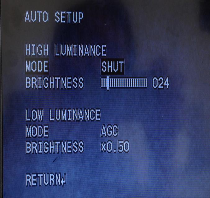
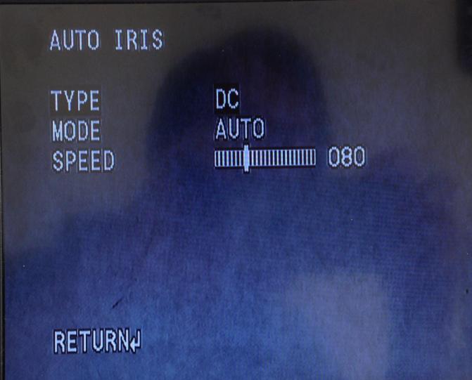
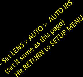
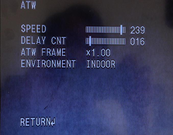
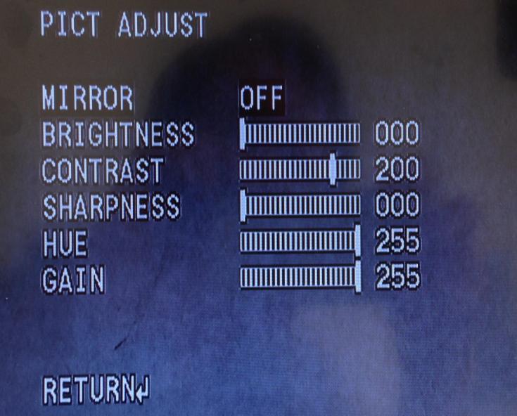
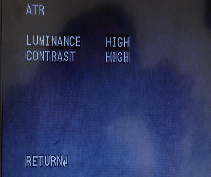
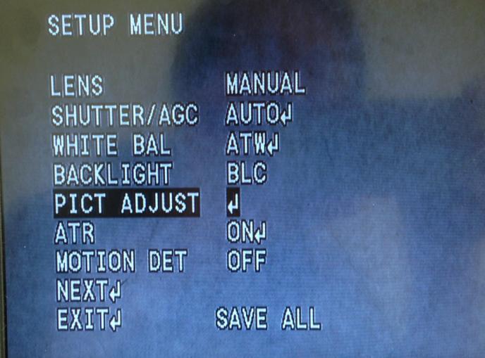
22 22 OSD On Screen Display (OSD) settings for the camera and monitor have been set by the manufacturer.. Please do not change the settings unless you have consulted with your distributor.. If you need to make an adjustment: - Press the toggle switch button straight down in order to get to the main menu. - Then, by clicking left, right, up or down on the toggle switch, you can highlight the area you want to adjust, make the adjustment, and save your settings by highlighting SAVE and clicking on the toggle button. - The toggle switch is on the wire extending from the camera. Monitor Settings
23 23
24 24

25 25
VG40 Video Goggle. User Manual. Doc no _02 Part no
 VG40 Video Goggle User Manual Doc no. 7-60-0710_02 Part no. 7-60-07100 0459 Copyright notice No part of this Manual or program may be reproduced, stored in a retrieval system, or transmitted, in any form
User Instructions. 16 SCB Sync Station.
 User Instructions 16 SCB Sync Station Contents Overview... 1 Specifications... 1 Compliance and approvals... 2 Safety instructions... 3 Set up... 4 How to charge multiple devices... 4 How to synchronize
OPERATION AND SERVICE MANUAL
 Integra Luxtec OPERATION AND SERVICE MANUAL EN Integra Luxtec For use with high power surgical light sources such as Integra Luxtec MLX 300W system. 1 Table of Contents Indications for Use...2 Contraindications...2
USER MANUAL. 22" Class Slim HD Widescreen Monitor L215DS
 USER MANUAL 22" Class Slim HD Widescreen Monitor L215DS TABLE OF CONTENTS 1 Getting Started Package Includes Installation 2 Control Panel / Back Panel Control Panel Back Panel 3 On Screen Display 4 Technical
USER MANUAL. 27 Full HD Widescreen LED Monitor L27ADS
 USER MANUAL 27 Full HD Widescreen LED Monitor L27ADS TABLE OF CONTENTS 1 Getting Started 2 Control Panel/ Back Panel 3 On Screen Display 4 Technical Specs 5 Care & Maintenance 6 Troubleshooting 7 Safety
USER MANUAL. 27 Full HD Widescreen LED Monitor L270E
 USER MANUAL 27 Full HD Widescreen LED Monitor L270E TABLE OF CONTENTS 1 Getting Started 2 Control Panel/ Back Panel 3 On Screen Display 4 Technical Specs 5 Care & Maintenance 6 Troubleshooting 7 Safety
Operation Manual VMS 3.0 Video System
 Operation Manual VMS 3.0 Video System for the AlterG Anti-Gravity Treadmill 1 This manual covers operation procedures for the following AlterG products: AlterG Video System model VMS 3.0 NOTE: The following
User Guide. Single-Link DVI Active Cable Extender. DVI-7171c
 User Guide Single-Link DVI Active Cable Extender DVI-7171c TABLE OF CONTENTS SECTION PAGE PRODUCT SAFETY...1 PRODUCT LIABILITY...1 1.0 INTRODUCTION...2 2.0 SPECIFICATIONS...3 3.0 PACKAGE CONTENTS...4 4.0
Installation Guide VL-MV10. Model No.
 Installation Guide Model Name Model No. Main Monitor Station VL-MV0 R Main monitor station is described as "main monitor" in this guide. R In this guide, the suffix of each model number (e.g., the "EX"
CM-S38901SV TVL IR Long Range camera
 5 40 TVL IR Long Range camera User s Guide CM-S38901SV SAFETY PRECAUTIONS WARNING 1. Be sure to use only the standard adapter that is specified in the specification sheet. Using any other adapter could
USER MANUAL. 27" 2K QHD LED Monitor L27HAS2K
 USER MANUAL 27" 2K QHD LED Monitor L27HAS2K TABLE OF CONTENTS 1 Getting Started 2 Control Panel/ Back Panel 3 On Screen Display 4 Technical Specs 5 Troubleshooting 6 Safety Info & FCC warning 1 GETTING
USER MANUAL. 28" 4K Ultra HD Monitor L28TN4K
 USER MANUAL 28" 4K Ultra HD Monitor L28TN4K TABLE OF CONTENTS 1 Getting Started 2 Control Panel/ Back Panel 3 On Screen Display 4 Technical Specs 5 Care & Maintenance 6 Troubleshooting 7 Safety Info &
AWT150C/AWT150CS/ AWT151C CCD Camera
 AWT150C/AWT150CS/ AWT151C CCD Camera ISSUED OCTOBER 2018 WARNING Failure to follow all instructions and safety precautions in this manual, in the vehicle and body manufacturers' manuals and on the safety
TV Ears Wireless Speaker User Manual
 TV Ears Wireless Speaker User Manual Congratulations! You ve taken the first step toward the TV Ears television experience. TV Ears Wireless System will help you hear TV better. To ensure the best TV listening
Kramer Electronics, Ltd. USER MANUAL. Model: VM Video Component Distributor
 Kramer Electronics, Ltd. USER MANUAL Model: VM-1045 Video Component Distributor Contents Contents 1 Introduction 1 2 Getting Started 1 2.1 Quick Start 1 3 Overview 3 4 Your VM-1045 Video Component Distributor
CM-S23349SV. Vari-Focal IR Bullet Camera
 Vari-Focal IR Bullet Camera User s Guide CM-S23349SV SAFETY PRECAUTIONS WARNING 1. Be sure to use only the standard adapter that is specified in the specification sheet. Using any other adapter could cause
Indoor/Outdoor Security System with Quad Monitor User s Manual
 Indoor/Outdoor Security System with Quad Monitor User s Manual 4919539 Important! Please read this booklet carefully before installing or using these units. WARNING - These units should ONLY be opened
USER MANUAL Full HD Widescreen LED Monitor L215ADS
 USER MANUAL 21.5 Full HD Widescreen LED Monitor L215ADS TABLE OF CONTENTS 1 Getting Started 2 Control Panel/ Back Panel 3 On Screen Display 4 Technical Specs 5 Care & Maintenance 6 Troubleshooting 7 Safety
USER MANUAL Full HD Widescreen LED Monitor L215IPS
 USER MANUAL 21.5 Full HD Widescreen LED Monitor L215IPS TABLE OF CONTENTS 1 Getting Started 2 Control Panel/ Back Panel 3 On Screen Display 4 Technical Specs 5 Care & Maintenance 6 Troubleshooting 7 Safety
VGA Extender over Single CAT 6 Cable with Audio Support. Model Extend both video and audio up to 1000 feet
 VGA Extender over Single CAT 6 Cable with Audio Support Model 103004 Extend both video and audio up to 1000 feet Utilize a Cat 6 cable instead of a bulky VGA cable Supports a local monitor and local speakers
Register your product and get support at SDV5122/27. EN User manual
 Register your product and get support at www.philips.com/welcome SDV5122/27 User manual Contents 1 Important 4 Safety 4 Notice for USA 5 Notice for Canada 5 Recycling 6 English 2 Your SDV5122 7 Overview
HOME THEATER. HDMI Selector Switches. Vanco Part Numbers (5x1) (3x1) Technical Support
 (3x1) Technical Support") HOME THEATER HDMI Selector Switches Vanco Part Numbers 280710 (5x1) 280711 (3x1) Technical Support www.vanco1.com info@vanco1.com 800-626-6445 DEAR CUSTOMER Thank you for purchasing this product. For optimum
HOME THEATER HDMI Selector Switches Vanco Part Numbers 280710 (5x1) 280711 (3x1) Technical Support www.vanco1.com info@vanco1.com 800-626-6445 DEAR CUSTOMER Thank you for purchasing this product. For optimum
Outdoor IR Audio Camera
 Outdoor IR Audio Camera User s Guide CM-S22326BW-AD SAFETY PRECAUTIONS WARNING 1. Be sure to use only the standard adapter that is specified in the specification sheet. Using any other adapter could cause
TV Connector user guide
 TV Connector user guide Thank you Thank you for choosing the TV Connector. The intended use of the TV Connector is to connect your hearing aids directly to your TV or audio source. Your TV Connector Hearing
LINK-MI LM-WHD05B. Wireless HDMI AV Transmission System. User Manual
 LINK-MI LM-WHD05B Wireless HDMI AV Transmission System User Manual Table of Contents 1.Important Information... 3 1.1 Safety Precautions... 3 1.2 Declaration of Conformity... 4 1.3 Trademark Information...
TV Ears TV Speaker Installation Guide
 TV Ears TV Speaker Installation Guide Safety Instructions 1. Read all instructions completely and heed all warnings. Install in accordance with TV Ears, Inc. s instructions. 2. Keep these instructions
HDMI 5x1 Switch B-240-HDSWTCH-5X1 INSTALLATION MANUAL
 HDMI 5x1 Switch B-240-HDSWTCH-5X1 INSTALLATION MANUAL IMPORTANT SAFETY INSTRUCTIONS To reduce the risk of fire or electric shock, read and follow all instructions and warnings in this manual. Keep this
Miniature Fiber-Optic 3G-SDI Extension Module. User s Manual (SDIX-100, SDIX-100C)
") Miniature Fiber-Optic 3G-SDI Extension Module User s Manual (SDIX-100, SDIX-100C) Manual Contents Manual Contents 1-0 Welcome!, Product Description 1-1 System Requirements for Setup 1-2 Installation 1-3
Miniature Fiber-Optic 3G-SDI Extension Module User s Manual (SDIX-100, SDIX-100C) Manual Contents Manual Contents 1-0 Welcome!, Product Description 1-1 System Requirements for Setup 1-2 Installation 1-3
INSTRUCTIONAL MANUAL FOR LCD ZOOM MICROSCOPE
 INSTRUCTIONAL MANUAL FOR LCD ZOOM MICROSCOPE ? 8 LCD Screen? 10.4 LCD Screen LCD Zoom Microscope Instruction Manual Please read the Instruction Manual carefully before installation and keep it for future
LF-IRX. 12 Month Limited Warranty LF-IRX. Remote Control Extender. Owner s manual. For customer service and technical information::
 12 Month Limited Warranty Audiovox Electronics Corporation (the company) warrants to the original purchaser of this product that should this product or any part thereof, under normal use and conditions,
TV Connector user guide
 TV Connector user guide Thank you Thank you for choosing the TV Connector. The intended use of the TV Connector is to connect your hearing aids directly to your TV or audio source. Your TV Connector Hearing
17 19 PROFESSIONAL LCD COLOUR MONITOR ART
 17 19 PROFESSIONAL LCD COLOUR MONITOR ART. 41657-41659 Via Don Arrigoni, 5 24020 Rovetta S. Lorenzo (Bergamo) http://www.comelit.eu e-mail:export.department@comelit.it WARNING: TO REDUCE THE RISK OF FIRE
HDMI WIRELESS EXTENDER/ RECEIVER. Vanco Part Number: HDWIRKIT HDWIR-RX. Technical Support
 HDMI WIRELESS EXTENDER/ RECEIVER Vanco Part Number: HDWIRKIT HDWIR-RX Technical Support www.vanco1.com techsupport@vanco1.com 800-626-6445 DEAR CUSTOMER Thank you for purchasing this product. For optimum
UDRC13 ACCESSORY CAMERA Owner s Manual
 UDRC13 ACCESSORY CAMERA Owner s Manual Compatible with UDR444 Wireless Video Surveillance System If any items are missing or damaged, contact our Customer Care Line immediately. Never use damaged products!
PLL1920M LED LCD Monitor
 PLL1920M LED LCD Monitor USER'S GUIDE www.planar.com Content Operation Instructions...1 Safety Precautions...2 First Setup...3 Front View of the Product...4 Rear View of the Product...5 Installation...6
PL2410W LCD Monitor USER'S GUIDE.
 PL2410W LCD Monitor USER'S GUIDE www.planar.com Content Operation Instructions...1 Safety Precautions...2 First Setup...3 Front View of the Product...4 Rear View of the Product...5 Quick Installation...6
DATA SHEET. The Advantys model STBDAI5260 Digital Input Module provides 2 isolated discrete input points that operate on a 115 VAC power source.
 Advantys STB Advantys STB Input Module DATA SHEET Description The Advantys model STBDAI5260 Digital Input Module provides 2 isolated discrete input points that operate on a 115 VAC power source. Features
PLL2210MW LED Monitor
 PLL2210MW LED Monitor USER'S GUIDE www.planar.com Content Operation Instructions...1 Safety Precautions...2 First Setup...3 Front View of the Product...4 Rear View of the Product...5 Quick Installation...6
COMMODORE 1802 COLOR MONITOR USER'S GUIDE
 COMMODORE 1802 COLOR MONITOR USER'S GUIDE Warning: This product includes critical mechanical and electrical parts which are essential for X radiation safety. For continued safety replace critical components
LTC 113x & LTC123x FlexiDome Series Fixed Dome Cameras
 LTC 113x & LTC123x FlexiDome Series Fixed Dome Cameras Eng Installation Instructions F D E NL I IMPORTANT SAFEGUARDS 1. Read Instructions All the safety and operating instructions should be read before
USERS GUIDE MCX-HTS. HDMI to 3G SDI Converter. Manual Number:
 USERS GUIDE MCX-HTS HDMI to 3G SDI Converter i Manual Number: 151226 SAFETY INSTRUCTIONS Please review the following safety precautions. If this is the first time using this model, then read this manual
ACCESSORIES MANUAL PART NUMBER: TNP500. Universal Tilt N Plug Interconnect Box USER'S GUIDE
 MANUAL PART NUMBER: 400-0091-003 TNP500 Universal Tilt N Plug Interconnect Box USER'S GUIDE INTRODUCTION Your purchase of the TNP100 Tilt N Plug Interconnect Box is greatly appreciated. We are sure you
DisplayPort Extender over 2 LC Fibers
 DisplayPort Extender over 2 LC Fibers Audio 3GSDI Embedder EXT-DP-CP-2FO User Manual Release A2 DisplayPort Extender over 2 LC Fibers Important Safety Instructions 1. Read these instructions. 2. Keep these
Children cannot always recognize potential hazards properly. This 5.1 system is not designed for operation in a heavy industry environment.
 5.1 FLAT PANEL SPEAKER SYSTEM WITH POWERED SUBWOOFER Table of Contents: SAFETY AND SERVICE... 2 Operational Safety... 2 Location... 2 Ambient Temperature... 3 Electromagnetic Compliance... 3 Service...
USER MANUAL Full HD Widescreen LED Monitor L236VA
 USER MANUAL 23.6 Full HD Widescreen LED Monitor L236VA TABLE OF CONTENTS 1 Getting Started 2 Control Panel/ Back Panel 3 On Screen Display 4 Technical Specs 5 Care & Maintenance 6 Troubleshooting 7 Safety
DDW36C Advanced Wireless Gateway - Safety and Installation Product Insert. Federal Communications Commission (FCC) Interference Statement
 Interference Statement") DDW36C Advanced Wireless Gateway - Safety and Installation Product Insert Federal Communications Commission (FCC) Interference Statement This equipment has been tested and found to comply with the limits
DDW36C Advanced Wireless Gateway - Safety and Installation Product Insert Federal Communications Commission (FCC) Interference Statement This equipment has been tested and found to comply with the limits
*Prefer. 600 MHz 4K ULTRA. 60Hz, 4:4:4. over one SC-Terminated Fiber-Optic Cable EXT-DP-4K600-1SC. User Manual. Release A1
 *Prefer 600 MHz 4K ULTRA 60Hz, 4:4:4 DisplayPort 1.2 Extender over one SC-Terminated Fiber-Optic Cable EXT-DP-4K600-1SC User Manual Release A1 Important Safety Instructions 1. Read these instructions.
ATTACHING & REMOVING THE BASE
 TV53DB ATTACHING & REMOVING THE BASE 1. To install or remove the neck, screw in or remove the 4 screws indicated in the picture. 2. To install the base, place the display unit flat on a table. Afterwards
Colour Explosion Proof Video Camera USER MANUAL VID-C
 Colour Explosion Proof Video Camera USER MANUAL VID-C Part Number: MAN-0036-00 Rev 4 Copyright 2002 Net Safety Monitoring Inc. Printed in Canada This manual is provided for informational purposes only.
MDA-2-HV. 1x2 Moblie Distribution Amplifier. Instruction Manual
 MDA-2-HV 1x2 Moblie Distribution Amplifier Instruction Manual Thank you for purchasing one of our products. Please read this manual before using this product. When using this product, always follow the
Kramer Electronics, Ltd. USER MANUAL. Model: 810B. Black Burst / Audio Generator
 Kramer Electronics, Ltd. USER MANUAL Model: 810B Black Burst / Audio Generator Contents Contents 1 Introduction 1 2 Getting Started 1 3 Your 810B Black Burst / Audio Generator 1 4 Connecting the 810B Black
ROUGH DRAFT. Guide. Installation. Signal Booster. Wilson. AG Pro 75 Smart Technology In-Building Wireless 800/1900 Signal Booster.
 Signal Booster Installation Guide Contents: AG Pro 75 Smart Technology In-Building Wireless 800/1900 Signal Booster Before Getting Started.... 1 Antenna Options & Accessories.................... 1 Easy
DSP x1 Color Screen Splitter Instruction Manual
 DSP-1200 2x1 Color Screen Splitter Instruction Manual Thank you for purchasing one of our products. Please read this manual before using this product. When using this product, always follow the instructions
Winmate Communication INC.
 20.1 Military Grade Display Model: R20L100-RKA2ML User s Manual Winmate Communication INC. May, 2011 1 IMPORTANT SAFETY INSTRUCTIONS Please read these instructions carefully before using the product and
User Guide. HDMI Fiber Optic Extender. DVI-7350a
 User Guide HDMI Fiber Optic Extender DVI-7350a Table of Contents Section Page Product Safety.................................... 1 1.0 Introduction...2 2.0 Specifications...3 3.0 Package Contents...3 4.0
INSTALLATION MANUAL. ST-CVTSD520-WSD-W Smoke Detector Covert Camera. v1.2 8/11/11 1
 INSTALLATION MANUAL ST-CVTSD520-WSD-W Smoke Detector Covert Camera v1.2 8/11/11 1 PACKAGE CONTENTS This package contains: One ST-CVTSD520-WSD-W smoke detector covert camera One installation manual Mounting
HD Digital MPEG2 Encoder / QAM Modulator
 HD Digital MPEG2 Encoder / QAM Modulator HDMI In QAM Out series Get Going Guide ZvPro 800 Series is a one or two-channel unencrypted HDMI-to-QAM MPEG 2 Encoder / QAM Modulator, all in a compact package
SM-816DT User s Manual. 2.4GHz Digital Wireless Outdoor/Indoor Camera with Night Vision and Audio
 SM-816DT User s Manual 2.4GHz Digital Wireless Outdoor/Indoor Camera with Night Vision and Audio Copyright 2012 This manual is furnished under license and may be used or copied only in accordance with
2x1 HDMI SWITCH. with Multiview and PIP Vanco Part Number: EVSW21MV
 2x1 HDMI SWITCH with Multiview and PIP Vanco Part Number: EVSW21MV 2x1 HDMI Switch with Multiview and Picture-in-Picture www.vanco1.com 800.626.6445 DEAR CUSTOMER Thank you for purchasing this product.
TVAC20000 User manual
 TVAC20000 User manual Version 01/2010 Original English user manual. Keep for future use. 10 Introduction Dear Customer, Thank you for purchasing this product. This product meets the requirements of the
 Register your product and get support at www.philips.com/welcome SWW1890 User manual Contents 1 Important 4 Safety 4 English 2 Your Philips Wireless HD Net Connect 5 What is in the box 5 3 Overview 6
Model Extend HDMI audio and video connections up to 300 feet. Add up to 8 additional receivers with a dedicated network switch
 HDMI Extender over Single CAT 6 Cable with IR Control Model 103002 Extend HDMI audio and video connections up to 300 feet Utilize existing Cat 6 wiring for an easy installation Add up to 8 additional receivers
HDBaseT RECEIVER B-540-RX-330-IR INSTALLATION MANUAL
 HDBaseT RECEIVER B-540-RX-330-IR INSTALLATION MANUAL IMPORTANT SAFETY INSTRUCTIONS To reduce the risk of fire or electric shock, read and follow all instructions and warnings in this manual. Keep this
ACCESSORIES MANUAL PART NUMBER: PRODUCT REVISION: 1 PNP202. Interconnect Box USER'S GUIDE
 MANUAL PART NUMBER: 400-0109-001 PRODUCT REVISION: 1 PNP202 Interconnect Box USER'S GUIDE INTRODUCTION Your purchase of the PNP202 Interconnect Box is greatly appreciated. We are sure you will find it
User Manual TP70L. HDBaseT Extender. All Rights Reserved. Version: TP70L2016V1.1
 User Manual TP70L HDBaseT Extender All Rights Reserved Version: TP70L2016V1.1 Preface Read this user manual carefully before using this product. Pictures shown in this manual is for reference only, different
ACCESSORIES MANUAL PART NUMBER: PRODUCT REVISION: 1 TNP100. Tilt N Plug Interconnect Box USER'S GUIDE
 MANUAL PART NUMBER: 400-0091-001 PRODUCT REVISION: 1 TNP100 Tilt N Plug Interconnect Box USER'S GUIDE INTRODUCTION Your purchase of the TNP100 Tilt N Plug Interconnect Box is greatly appreciated. We are
Black & White Wireless Video Surveillance System
 MODEL: 2BWIR Black & White Wireless Video Surveillance System INSTALLATION MANUAL V1.0 N517 Camera Monitor - Compact 2.4 GHz Mini Black & White Camera - 5.5 High Resolution CRT - Sturdy Design with Metal
4K Video Solutions HDMI SWITCHER. User Manual 4 1 HDSW K
 4K Video Solutions HDMI SWITCHER User Manual 4 1 HDSW-2041-4K A Thank you for choosing Kopul. THe Kopul HDSW-2041-4K HDMI switcher lets you select from four HDMI sources, and output them to a single HD
In-Line or 75 Ohm In-Line
 or 5 Ohm 1dB Adjustable Gain 800/1900 Smart Technology Contents: Quick Install Overview.... 2 Installation Diagram.... Understanding the Lights... 9 Warnings and Recommendations....11 Appearance of device
HDBaseT RECEIVER B-520-RX-330-IR INSTALLATION MANUAL
 HDBaseT RECEIVER B-520-RX-330- INSTALLATION MANUAL IMPORTANT SAFETY INSTRUCTIONS To reduce the risk of fire or electric shock, read and follow all instructions and warnings in this manual. Keep this manual
In-Ceiling Electric Motorized Front Projection Screen Evanesce Series. User s Guide
 In-Ceiling Electric Motorized Front Projection Screen Evanesce Series User s Guide Important Safety & Warning Precautions Make sure to read this user s guide and follow the procedures below. Caution: The
INSTALLATION MANUAL. ST-CVTMD420-WPIR-W Covert Motion Detection Color Camera. v1.3 8/11/11 1
 INSTALLATION MANUAL ST-CVTMD420-WPIR-W Covert Motion Detection Color Camera v1.3 8/11/11 1 PACKAGE CONTENTS This package contains: One ST-CVTMD420-WPIR-W covert motion detection camera One installation
2.4 GHz WIRELESS SURVEILLANCE SYSTEM
 2.4 GHz WIRELESS SURVEILLANCE SYSTEM Operating Instructions Tested Comply With FCC Standards Model # TBM-18 BEFORE OPERATING THIS PRODUCT, READ, UNDERSTAND, AND FOLLOW THESE INSTRUCTIONS. Be sure to save
MONOPRICE. Blackbird 4K HDMI Extender. User's Manual P/N 24281
 MONOPRICE Blackbird 4K HDMI Extender P/N 24281 User's Manual SAFETY WARNINGS AND GUIDELINES Please read this entire manual before using this device, paying extra attention to these safety warnings and
DisplayPort Extender over 2 LC Fibers
 DisplayPort Extender over 2 LC Fibers Audio 3GSDI Embedder EXT-DP-CP-2FO User Manual Release A2 DisplayPort Extender over 2 LC Fibers Important Safety Instructions 1. Read these instructions. 2. Keep these
PRODUCT MANUAL : 1x8 Splitter/Extender : Receiver (Sold Separately)
") PRODUCT MANUAL Product Name: S-VGA Splitter/Extenders over Category 5e/Cat6 Cable Part Numbers: 90-12116: 1x2 Splitter/Extender 90-12112: 1x8 Splitter/Extender 90-12113: Receiver (Sold Separately) WARNING:
PRODUCT MANUAL Product Name: S-VGA Splitter/Extenders over Category 5e/Cat6 Cable Part Numbers: 90-12116: 1x2 Splitter/Extender 90-12112: 1x8 Splitter/Extender 90-12113: Receiver (Sold Separately) WARNING:
Kramer Electronics, Ltd. USER MANUAL. Model: Power Amplifier
 Kramer Electronics, Ltd. USER MANUAL Model: 900 Power Amplifier Contents Contents 1 Introduction 1 2 Getting Started 1 3 Overview 1 4 Your 900 Power Amplifier 2 5 Connecting your 900 Power Amplifier 4
USER MANUAL. Kramer Electronics, Ltd. Models:
 Kramer Electronics, Ltd. USER MANUAL Models: 707, Video Audio Line Transmitter 708, Video Audio Line Receiver 709, Y/C Line Transmitter 710, Y/C Line Receiver 711xl, Video-Audio Line Transmitter 712xl,
Kramer Electronics, Ltd. USER MANUAL. Models: PT-102AN, 1:2 Audio DA PT-102SN, 1:2 s-video DA
 Kramer Electronics, Ltd. USER MANUAL Models: PT-102AN, 1:2 Audio DA PT-102SN, 1:2 s-video DA Contents Contents 1 Introduction 1 2 Getting Started 1 2.1 Quick Start 1 3 Overview 3 3.1 About the PT102AN
SEL-3405 High-Accuracy IRIG-B Fiber-Optic Transceiver
 SEL-3405 High-Accuracy IRIG-B Fiber-Optic Transceiver Accurate IRIG-B Over Fiber Optics Major Features and Benefits The SEL-3405 High-Accuracy IRIG-B Fiber-Optic Transceiver can send high-accuracy demodulated
User Manual. Model HCX-11 HDMI Coax Extender. Five-Coax Extender Model HCX-11. Five-Coax Extender Model HCX-11
 User Manual Model HCX-11 Coax Extender INTERNAL CLOCK B 800-322-8346 859-233-4599 www.audioauthority.com COAX INPUT R G B CLOCK INTERNAL COAX OUTPUT Five-Coax Extender Model HCX-11 G R 12V DC LINK INPUT
1x4, 1x8, 1x12, 1x16 VGA Extender / Splitter over Single CAT5
 1x4, 1x8, 1x12, 1x16 VGA Extender / Splitter over Single CAT5 User s Guide Models VGA-C5-SP-4 VGA-C5-SP-8 VGA-C5-SP-12 VGA-C5-SP-16 2009 Avenview Inc. All rights reserved. The contents of this document
Kramer Electronics, Ltd. USER MANUAL. Model: VA-100P-5. Power Supply
 Kramer Electronics, Ltd. USER MANUAL Model: VA-100P-5 Power Supply Contents Contents 1 Introduction 1 2 Getting Started 1 2.1 Quick Start 1 3 Overview 2 4 Your Power Supply 3 5 Using the Power Supply 4
ALO 030 MKII. 30 Watt DMX LED scanner. User manual
 ALO 030 MKII 30 Watt DMX LED scanner User manual Safety instructions WARNING! Always keep this device away from moisture and rain! Hazardous electrical shocks may occur! WARNING! Only connect this device
Kramer Electronics, Ltd. USER MANUAL. Models: TR-1YC, s-video Isolation Transformer TR-2YC, s-video Dual Isolation Transformers
 Kramer Electronics, Ltd. USER MANUAL Models: TR-1YC, s-video Isolation Transformer TR-2YC, s-video Dual Isolation Transformers Contents Contents 1 Introduction 1 2 Getting Started 1 2.1 Quick Start 1 3
PXL2760MW LED LCD Monitor
 PXL2760MW LED LCD Monitor USER'S GUIDE www.planar.com Content Operation Instructions...1 Safety Precautions...2 Package Overview...3 First Setup...4 Front View of the Product...5 Rear View of the Product...6
HD Digital MPEG2 Encoder / QAM Modulator
 HD Digital MPEG2 Encoder / QAM Modulator YPrPb VGA In QAM Out series Get Going Guide ZvPro 600 Series is a one or two-channel Component or VGA-to-QAM MPEG 2 Encoder/ Modulator, all in a compact package
DA1909 COMPUTER VIDEO LINE DRIVER WITH EQUALIZATION USER S GUIDE
 MANUAL PART NUMBER: 400-0108-002 PRODUCT REVISION: 1 COMPUTER VIDEO LINE DRIVER WITH EQUALIZATION USER S GUIDE INTRODUCTION Altinex appreciates your purchase of the Line Driver. We are sure you will find
User Manual TL-TP70-HDIR 70m Extender with ARC and IR All Rights Reserved Version: TL-TP70-HDIR_180723
 User Manual TL-TP70-HDIR 70m Extender with ARC and IR All Rights Reserved Version: TL-TP70-HDIR_180723 Preface Read this user manual carefully before using this product. Pictures shown in this manual is
ENGLISH Antenna Distributor
 MANUAL ENGLISH Antenna Distributor V1 Highlite International B.V. Vestastraat 2 6468 EX Kerkrade the Netherlands Table of contents Warning... 2 Safety Instructions... 2 Operating Determinations... 4 Connection
COMPOSITE VIDEO (BNC) TO VGA VIDEO FORMAT CONVERTER AND SCALER AT-RGB110
 TO VGA VIDEO FORMAT CONVERTER AND SCALER AT-RGB110") User Manual COMPOSITE VIDEO (BNC) TO VGA VIDEO FORMAT CONVERTER AND SCALER AT-RGB110 TABLE OF CONTENTS 1. Introduction... 2 2. Package Contents... 2 3. Features... 2 4. Specification... 2 5. Panel Description...
User Manual COMPOSITE VIDEO (BNC) TO VGA VIDEO FORMAT CONVERTER AND SCALER AT-RGB110 TABLE OF CONTENTS 1. Introduction... 2 2. Package Contents... 2 3. Features... 2 4. Specification... 2 5. Panel Description...
Kramer Electronics, Ltd.
 Kramer Electronics, Ltd. Preliminary USER MANUAL Model: 840H HDMI Pattern Generator Contents Contents 1 Introduction 1 2 Getting Started 1 3 Overview 2 3.1 Quick Start 3 4 Your 840H HDMI Pattern Generator
VGA & Audio Receiver SET over Single CAT5 with RGB Delay Control
 VGA & Audio Receiver SET over Single CAT5 with RGB Delay Control Model #: VGA-C5A-R 2010 Avenview Inc. All rights reserved. The contents of this document are provided in connection with Avenview Inc. (
User Guide. Centrex Recording Interface
 User Guide Centrex Recording Interface Table of Contents Introduction... 2 The Meridian Business Set... 3 Key Numbering Plan (18 button add-on)... 4 Key Numbering Plan (36 button add-on)... 5 Key Numbering
2nd Edition. Quick Start Guide. getawair.com
 2nd Edition Quick Start Guide getawair.com Stay Healthy Awair tracks toxins and chemicals in your air and gives you personalized recommendations to help you stay safe and healthy. Sensors Fine Dust (PM2.5)
User Manual PS-684. HDBaseT Extender Kit 70m. All Rights Reserved. Version: UHBT70P_2016V1.2
 User Manual PS-684 All Rights Reserved Version: UHBT70P_2016V1.2 Preface Read this user manual carefully before using this product. Pictures shown in this manual is for reference only, different model
blink USER GUIDE Bluetooth capable Reclocker Wyred 4 Sound. All rights reserved. v1.0
 blink Bluetooth capable Reclocker USER GUIDE Wyred 4 Sound. All rights reserved. v1.0 Table of Contents READ FIRST Important 1 Package contents 1 About the blink Bluetooth Streamer/Reclocker 1 Connectivity
LCD VALUE SERIES (32 inches)
") LCD VALUE SERIES (32 inches) http://www.orionimages.com All contents of this document may change without prior notice, and actual product appearance may differ from that depicted herein 1. SAFETY INSTRUCTION
LCD VALUE SERIES (32 inches) http://www.orionimages.com All contents of this document may change without prior notice, and actual product appearance may differ from that depicted herein 1. SAFETY INSTRUCTION
.Power Distribution Center. PD-1. Instruction Manual
 .Power Distribution Center. PD-1 Instruction Manual www.datavideo-tek.com 1 Contents Warnings and Precautions... 3 Warranty... 4 Standard Warranty... 4 Two Year Warranty... 4 Disposal... 4 Packing List...
HDBaseT RECEIVER B-520-RX-230-IR INSTALLATION MANUAL
 HDBaseT RECEIVER B-520-RX-230-IR INSTALLATION MANUAL IMPORTANT SAFETY INSTRUCTIONS To reduce the risk of fire or electric shock, read and follow all instructions and warnings in this manual. Keep this