Vector Network Analyzers
|
|
|
- Collin Spencer
- 5 years ago
- Views:
Transcription

1 Service Manual Vector Network Analyzers R&S ZVB 4 / ZVB 8 / ZVB 14 / ZVB /06 / 08/10 / 14/17/19 / 0/3/5 Test and Measurement
2 R&S is a registered trademark of Rohde & Schwarz GmbH & Co. KG. Trade names are trademarks of the owners. The instrument includes software developed by the OpenSSL Project for use in the OpenSSL Toolkit ( It includes cryptographic software written by Eric Young (eay@cryptsoft.com) and software written by Tim Hudson (tjh@cryptsoft.com). The verbatim license texts are provided in on the user documentation CD-ROM (included in delivery).
3 R&S ZVB Chapter Overview Chapter Overview Safety Instructions Spare Parts Express Service List of R&S Representatives Contents of Manuals for Vector Network Analyzers R&S ZVB Service and Repair Chapter 1: Performance Test Chapter : Alignment Chapter 3: Repair Chapter 4: Software Update / Installation of Options Chapter 5: Documents RE E-4
4
5 R&S ZVB Index Index A Alignment....3 Frequency accuracy....6 Frequency response correction....7,.9 Level accuracy....9 Manual....4 Reference frequency....6 Test equipment....4 B Battery Replacement Block circuit diagram , 5.19 Block diagram Explanation Board replacement DC/AC converter Disk drive Fan Front hood Front module processor A Frontend A , 3.47 LCD Motherboard A Network Controller Board A130, A Power supply Power supply Reflectometer RM Switching foil Synthesizer Board USB Board Board Replacement Battery Boards Overview Boot problems Troubleshooting D Disk drive Replacement Documents F Fan Replacement Frequency accuracy Alignment....6 Check. 1.4, 1.9, 1.11, 1.1, 1.13, 1.14, 1.15, 1.16, 1.17 Frequency Reference Board A100 Replacement Frequency response Correction....7,.9 Front hood Front module processor Function Replacement Front unit Frontend Repelcement , 3.47 Function description H Hard Disk Replacement Hard Disk battery Replacement I Instrument construction K Keyboard Function Replacement L LC display LCD Replacement Level accuracy Alignment...9 Lithium battery Replacement LO Divider A600 Replacement M Manual alignment...4 Mechanical Drawings Menu, service...3 Microwave converter Replacement Motherboard Function Replacement N Network Controller Board A130, A140 Replacement O OCXO Function Option B4 Function FSU-B9 Function Installation...4. List...4. P Password...3 Performance test Frequency accuracy...1.4, 1.9, , 1.13, 1.14, 1.15 Harmonics suppression Level accuracy...1.6, I.1 E-4
6 Index R&S ZVB Level linearity , 1.8 Protocol Performance Test Frequency accuracy , 1.17 Power cables Power supply Function Replacement Replacement Power-up problems Precision attenuator Function , 3.1 R Reflectometer RM8 Replacement Refurbished Modules Repairs Replacement Bridge Unit Coupler Unit Generator and Receiver Cover Generator Board Inner Conductor of a Port Connector Receiver Board Reflectometer Fan Reflectometer RM Replacement Boards Replacing Boards S Shipping Instrument Module Software update Spare parts electrical parts...5.5, 5.19 list of all parts Ordering...5. Refurbished Modules...5. Synthesizer Replacement T Test equipment Alignment...4 Performance test...1. Test equpment Troubleshooting Tracking generator Function Troubbleshooting Power-up problems Troubleshooting Troubleshooting Boot problems Troubleshooting Selftest , 3.63, 3.68 U USB Board Board replacement I. E-4
7 Procedure in Case of Service and Ordering of Spare Parts This section contains information on shipping an instrument to your service center and ordering spare parts. Please contact your local Rohde & Schwarz service center if you need service or repair work of your equipment or to order spare parts. The list of the Rohde & Schwarz representatives is provided at the beginning of this service manual. You can find the current address of your representative on our homepage Navigate to Service & Support / Service Locations. Shipping the Instrument We require the following information in order to answer your inquiry fast and correctly and to determine whether the warranty is still valid for your instrument: Instrument model Serial number Firmware version Must the instrument be returned with this firmware? Detailed error description in case of repair Indication of desired calibration Contact person for possible questions In some countries, an RMA process is available for the return shipment of the instrument. For details, contact your local representative. When shipping the instrument, be careful to provide for sufficient mechanical and antistatic protection. Use the original packaging for transporting or shipping the instrument. The protective caps for the front and rear prevent damage to the operating elements and the connectors. If you do not use the original packaging, provide for sufficient padding to prevent the instrument from slipping inside the box. Wrap antistatic packing foil around the instrument to protect it from electrostatic charging. Rohde & Schwarz offers repair and calibrations of the test systems it produces. The calibration documentation fulfills ISO 1705 requirements. Shipping Defective Modules Also when shipping a module, be careful to provide for sufficient mechanical and antistatic protection. Ship the module in a sturdy, padded box. Wrap the module in antistatic foil. If the packaging is only antistatic but not conductive, additional conductive packaging is required. The additional packaging is not required if the tightly fitting packaging is conductive. Exception: If the module contains a battery, the tightly fitting packaging must always consist of antistatic, nonchargeable material to protect the battery from being discharged
8 Ordering Spare Parts To deliver spare parts promptly and correctly, we need the following information: Stock number (see list of spare parts in chapter "Documents") Designation Component number according to list of spare parts Number of pieces Instrument type for which the spare part is needed Instrument stock number Instrument serial number Contact person for possible questions Refurbished Modules Refurbished modules are an economical alternative to original modules. Bear in mind that refurbished modules are not new, but repaired and fully tested parts. They may have traces from use, but they are electrically and mechanically equivalent to new modules. Your Rohde & Schwarz representative will be happy to inform you about which modules are available as refurbished modules. Taking Back Defective Replaced Modules Defective modules of the replacement program which cannot be repaired are taken back within three months following delivery. A repurchasing value is credited. Excluded are parts which cannot be repaired, e.g. printed boards that are burnt, broken or damaged by attempts to repair them, incomplete modules, and parts with severe mechanical damage. Please return the defective replacement modules, together with the accompanying document for returned merchandise, which you received with the spare module. We need the following information: Stock number, serial number and designation of the removed part Detailed error description Stock number, serial number and type of instrument from which the module was removed Date of removal Name of the engineer/technician who replaced the module R&S ordering number Service reference number (if available)
9 FSQ FVREF "Überschrift " \* MERGEFORMAT Fehler! Formatvorlage nicht definiert. R&S ZVB Contents Table of Contents Chapter 1 "Performance Test" 1 Performance Test Preliminary Remarks Test Equipment and Accessories...1. Performance Test Checking the Frequency Uncertainty Checking the Harmonics Checking the Maximum Output Power Checking the Accuracy of Output Power Checking the Output Linearity Checking the Power Measurement Uncertainty Checking the Input Linearity Checking the Input Noise Level Checking the Matching (raw) Checking the Dynamic Range Checking the Dynamic Range reduced due to Spurious Checking the DC Measurement Inputs Checking the optional R&S ZVB0-B80 Low Frequency Extension Checking the optional R&S ZVB0-B81 External Testset Performance Test Report I 1.1 E 4
10
11 R&S ZVB Preliminary Remarks 1 Performance Test Preliminary Remarks The required characteristics of the network analyzer are checked after a warm up time of at least 60 minutes; this ensures that the guaranteed data is met. The values stated in the following sections are not guaranteed data; only the specifications in the data sheet are binding. The values in the data sheet are guaranteed limits. Because of the measurement errors that arise, these limits must be increased to encompass the tolerances of the measuring equipment used for the performance test. Entries for the measurement are represented in the following way: [<KEY>] Press a front panel key, e.g. [SPAN] [<SOFTKEY>] Press a softkey, e.g. [MARKER > PEAK] [<nn unit>] Enter a value + terminate the entry with a unit, e.g. [1 khz] Consecutive entries are separated with a [ : ], e.g. [ Meas Bandwidth : 1 khz] E 4
12 Performance Test R&S ZVB Test Equipment and Accessories Item Type of equipment Recommended characteristics or features Recommended model R&S Order No. Application 1 Spectrum analyzer a) Counter mode: Min. resolution: 100 Hz Max. rel. frequency deviation: 10 6 b) Linearity Max. departure from linearity (σ): 0.06 db c) Frequency response: 50 MHz to 4 GHz: < 1 db 4 GHz to 8 GHz: < 1.5 db 8 GHz to 0 GHz: < db R&S FSU Frequency uncertainty Harmonics Output linearity Input linearity Power sensor N, 50 Ω. 300 khz to 8 GHz RSS error < 0.1 db VSWR < 1. R&S NRP Z Max. output power Accuracy of output power Power measurement uncertainty on R&S ZVB4/8 Power sensor 3.5mm, 50 Ω. 10 MHz to 0 GHz RSS error < 0.1 db VSWR < 1.5 R&S NRP Z Max. output power Accuracy of output power Power measurement uncertainty on R&S ZVB14/0 Power meter 300 khz to 0 GHz R&S NRVD + Sensor R&S ZV Z Max output power Accuracy of output power Power measurement uncertainty 4 Calibration kit N, 50 Ω. 300 khz to 8 GHz. R&S ZV Z Input linearity Matching port 1 to port 4 Input noise level on R&S ZVB4/8 4 Calibration kit 3.5 mm, 50 Ω. 10 MHz to 0 GHz. R&S ZV Z Input linearity Matching port 1 to port 4 Input noise level on R&S ZVB14/0 5 Signal generator 300 khz to 0 GHz, Power = 40 dbm to 10 dbm R&S SMR7 with Option R&S SMR B Power measurement uncertainty 6 Power splitter N, 50 Ohm, Γ eq < 0.05 (50 MHz to 8 GHz) Output tracking < 0.15 db 6 Power splitter 3.5mm, 50 Ohm, Output tracking < 0.5 db R&S SML01 Weinschel 1870A Weinschel Power measurement uncertainty Power measurement uncertainty 7 Test cable N(male) N(male), approx. 1.5 m Frequency uncertainty Harmonics Matching port 1 to port 4 Power measurement uncertainty Input linearity on R&S ZVB4/ E 4
13 R&S ZVB Test Equipment and Accessories Item Type of equipment Recommended characteristics or features Recommended model R&S Order No. Application 7 Test cable 3.5mm(male) 3.5 mm (female), approx. 1.5 m Frequency uncertainty Harmonics Matching port 1 to port 4 Power measurement uncertainty Input linearity on R&S ZVB14/0 8 BNC cable Male male, approx. 1.5 m General: Device synchronisation 9 DC power supply 10 Multimeter MU < 0.%, DC range 1 V, 10 V 11 Conn. Cables for DC inputs 1 V to +1 V R&S NGSM 3/ DC meas inputs R&S URE DC meas inputs R&S ZV Z DC meas inputs E 4
14 Performance Test R&S ZVB Performance Test Compare with data sheet Checking the Frequency Uncertainty Instrument: Spectrum analyzer (see Chapter Test Equipment, Item1) Test cable (see Chapter Test Equipment, Item7) Test setup: Connect the spectrum analyzer to (port to port 4) Spectrum analyzer settings: [ PRESET ] [ FREQ : 1 GHz ] [ SPAN : 50 khz ] [ BW : MANUAL RES BW : 10 khz ] [ MARKER : MARKER MODE : FREQ COUNT ] [ AMPT : REF LEVEL : 10 dbm] R&S ZVB settings Select [System : Internal Reference] [ Preset ] [ Meas :Wave Quantities: a1 Src Port 1] [ Sweep : Sweep Type : CW Mode : CW Frequency : 1 GHz; Power : 0 dbm] [ Sweep : Single : Restart] Measurement: Read off the frequency indicated by the marker. Frequency deviation = marker value 1 GHz Max. frequency deviation... see Performance Test Report E 4
15 R&S ZVB Performance Test Checking the Harmonics Instrument: Spectrum analyzer (see Chapter "Test Equipment", Item1) Test cable (see Chapter Test Equipment", Item7) Test setup: Connect the spectrum analyzer to port1 (port to port 4) Spectrum analyzer settings: Note: Synchronize the reference oscillators in the spectrum analyzer and in the R&S ZVB. [ PRESET ] [ FREQ : f GEN, * f GEN, 3* f GEN *] [ SPAN : ZERO SPAN ] [ BW : MANUAL RES BW : 100 Hz ] [ MARKER : DETECTOR : RMS ] [ AMPT : REF LEVEL : 10 dbm] * For measurement frequencies, see Performance Test Report {fgen}. R&S ZVB settings: [ Preset ] [ Meas : Wave Quantities: a1 Src Port 1 (a Src Port, a3 Src Port 3, a4 Src Port 4)] [ Sweep : Sweep Type : CW Mode : CW Frequency : {f GEN *} ; Power : 8 dbm ] [ Sweep : Single : Restart] * For measurement frequencies, see Performance Test Report {fgen}. Measurement: Calculation: Read off the levels L n*fgen (n = 1,, 3) indicated by the spectrum analyzer s markers. Harmonics = L n*f gen L fgen cable loss (in db) The cable loss corresponds to the S 1 of the test cable used between the fundamental and the measured harmonic (S 1 is negative) E 4
16 Performance Test R&S ZVB Checking the Maximum Output Power Instrument: Power sensor or Power meter with power sensor (see Chapter Test Equipment, Item) Test setup: Connect power sensor to port1 (port to port 4) Power sensor settings: For measurement frequencies, see Performance Test Report {f GEN *}. R&S ZVB settings: [ Preset ] [ Meas : Wave Quantities: a1 Src Port 1 (a Src Port to a4 Src Port 4)] [ Sweep : Sweep Type : CW Mode : CW Frequency : {f GEN *} ; Power : 16 dbm] [ Sweep : Single : Restart] * For measurement frequencies see the Performance Test Report {f GEN}. Measurement: Read off the level indicated by the power meter. Max. power... see Performance Test Report E 4
17 R&S ZVB Performance Test Checking the Accuracy of Output Power Instrument: Power sensor or Power meter with power sensor (see Chapter Test Equipment, Item) Test setup: Connect the power sensor to port 1 (port to port 4) Power sensor settings: For measurement frequencies, see Performance Test Report {f GEN *}. R&S ZVB settings: [ Preset ] [ Meas :Wave Quantities: a1 Src Port 1 (a Src Port, a3 Src Port 3, a4 Src Port 4)] [ Sweep : Sweep Type : CW Mode : CW Frequency : {f GEN *} ; Power : 10 dbm] [ Mode : ALC : On] [ Sweep : Single : Restart] * For measurement frequencies, see Performance Test Report {f GEN}. Measurement: Read off the levels indicated by the power sensor Level deviation = L SENSOR ( 10 dbm) E 4
18 Performance Test R&S ZVB Checking the Output Linearity Instrument: Spectrum analyzer (see Chapter Test Equipment, Item1) Test cable (see Chapter Test Equipment, Item7) Test setup: Connect the spectrum analyzer to port 1(port to port 4) Spectrum analyzer settings: Note: Synchronize the reference oscillators in the spectrum analyzer and in the R&S ZVB : [ PRESET ] [ FREQ : f GEN *] [ SPAN : ZERO SPAN ] [ BW : MANUAL RES BW : 100 Hz ] [ MARKER : DETECTOR : RMS ] [ AMPT : REF LEVEL : 5 dbm] [ Mode : ALC : On] * For measurement frequencies, see Performance Test Report {fgen}. R&S ZVB settings: [ Preset ] [ Meas : Wave Quantities: a1 Src Port 1 (a Src Port, a3 Src Port 3, a4 Src Port 4)] [ Sweep : Sweep Type : CW Mode : CW Frequency : {f GEN *} ; Power : {l GEN *}] [ Sweep : Single : Restart] * For measurement frequencies {fgen} and levels {l GEN}, see Performance Test Report Measurement: Read the spectrum analyzer s marker values (level L). Calculation: The measured values are referred to the level at the R&S ZVB setting of 10 dbm. Calculating the generator level linearity: Level linearity = L 10dBm step width (in db) Step width = l gen ( 10 dbm) (reference) E 4
19 R&S ZVB Performance Test Checking the Power Measurement Uncertainty Instrument: Power sensor or Power meter with power sensor (see Chapter Test Equipment, Item) Signal generator (see Chapter Test Equipment, Item5) Power splitter (see Chapter Test Equipment, Item6) Calibration kit (see Chapter Test Equipment, Item4) Test cable (see Chapter Test Equipment, Item7) Preparation/ test setup: Connect the signal generator to the power splitter input using the test cable. Connect the power sensor to a power splitter output Connect the other power splitter output to port1 (port to port 4) using an adapter from the calibration kit The reference oscillators in the signal generator and in the R&S ZVB must be synchronized. R&S ZVB settings: [ Preset ] [ Meas : Wave Quantities: b1 Src Port 1 (b Src Port, b3 Src Port 3, b4 Src Port 4)] [ Power : RF Off ] [ Meas Bandwidth : 100 Hz ] [ Marker ] [ Sweep : Sweep Type : CW Mode : CW Frequency : {f GEN *}] [ Sweep : Single : Restart] * For the measurement frequencies, see Performance Test Report {fgen}. Measurement: Signal generator : CW Mode, Frequency: f gen Signal generator level: 5 dbm Adjust the signal generator level so that the power meter reads 0 db +/ 0. db Determine the signal generator level that gives 10 dbm at the splitter output. This level is required for the following measurement, Checking Receiver Linearity. Read off the power meter display and the R&S ZVB marker values. Level error = L ZVB L PS E 4
20 Performance Test R&S ZVB Checking the Input Linearity Instrument: Calibration kit (see Chapter Test Equipment, Item4) R&S ZVB settings: [ Preset ] [ Meas : Ratios: b1/a1 Src Port 1] [ Meas : Ratios: b/a Src Port ] [ Meas : Ratios: b3/a3 Src Port 3] [ Meas : Ratios: b4/a4 Src Port 4] [ Meas Bandwidth : 10 Hz ] [ Marker] [ Sweep : Sweep Type : Power : Start 40dBm : Stop 10dBm : CW Frequency : {f GEN *}] [ Sweep : Single : Restart] * For measurement frequencies, see Performance Test Report {fgen} 1.Test setup: Connect a open male to port 1 (port to port 4) 1. Measurement: [ Trace Funct ] [ Data > Mem ] [ Show Mem : off ]. Test setup: Connect a short male to port 1 (port to port 4). Measurement: [ Math = Data/Mem : on ] Set Ref Marker to 10dBm Select Delta Mode Set Marker1 to 40dBm up to +10dBm by 5dB steps Read off the differences of the Marker Values displayed by the R&S ZVB E 4
21 R&S ZVB Performance Test Checking the Input Noise Level Test equipment Calibration kit (see Chapter Test Equipment, Item4) Test setup: Connect the Match Male from the calibration kit to port 1 (port to port 4) R&S ZVB settings: [ Preset ] [ Meas : Wave Quantities: b1 Src Port 1 (b Src Port, b3 Src Port 3, b4 Src Port 4)] [ Power : RF Off ] [ Meas Bandwidth : 10 Hz ] [ Marker ] [ Sweep : Sweep Type : CW Mode : CW Frequency : {f GEN *}] Service Function (see chapter 3 Service Functions, Service Level ) [ Measure : Wave Quantities : More Wave Quantities : Properties : Detector : RMS: Meas. Time: 500ms] [ Sweep : Single : Restart] * For measurement frequencies, see Performance Test Report {fgen}. Measurement: Read off the noise level indicated by the markers on the DUT E 4
22 Performance Test R&S ZVB Checking the Matching (raw) Instrument: Calibration kit (see Chapter Test Equipment, Item4) Test cable (see Chapter Test Equipment, Item7) 1. Preparation/ test setup: Connect the test cable to port 1 on the R&S ZVB and perform a 1 port calibration at the end of the cable. R&S ZVB settings: [ Meas : S11] [ Marker ] [ Add Channnel + Trace ] [ Meas : S (S33, S44) ] [ Power : 40 dbm ] [ Trace Funct ] [ Show Data : off ] [ Trace Select : Trc 1 ] Connect the end of the test cable to port (port3, port 4) on the R&S ZVB. 1. Measurement Read off the network analyzer s marker values (for marker frequencies see Performance Test Report) R&S ZVB settings: [ Power : 40 dbm ] [ Trace Funct ] [ Show Data : off ] [ Trace Select : Trc ] [ Trace Funct ] [ Show Data : on ] [ Meas : S] [ Marker ]. Preparation/ test setup: Set port power to 10 dbm Connect the test cable to port on the R&S ZVB and perform a 1 port calibration at the end of the cable. Connect the end of the test cable to port 1 on the R&S ZVB.. Measurement Read off the network analyzer s marker values (for marker frequencies see Performance Test Report) E 4
23 R&S ZVB Performance Test Checking the Dynamic Range Test equipment: Calibration kit N (see Chapter Test Equipment, Item 4) Test setup: Connect Short Male to port1 and port (port 3 and port 4) (use Short Female with Through Male as a second Short Male) R&S ZVB settings: [ Preset ] [ Meas : Ratios : b1/a Drive Port ] [ Meas : Ratios: b/a1 Drive Port 1] [ Meas : Ratios: b3/a4 Drive Port 4] [ Meas : Ratios: b4/a3 Drive Port 3] [ Power : Max. spec. Power ] [ Meas Bandwidth : 10 Hz ] [ Marker ] [ Sweep : Sweep Type : CW Mode : CW Frequency : {f GEN *}] Service Function (see chapter 3 "Service Functions", Service Level ) [ Measure : Wave Quantities : More Wave Quantities : Properties : Detector : RMS: Meas. Time: 500ms] [ Sweep : Single : Restart] * For measurement frequencies, see Performance Test Report {fgen}. Measurement: Calculation: Read off marker value Nominal dynamic range:... see Performance Test Report E 4
24 Performance Test R&S ZVB Checking the Dynamic Range reduced due to Spurious Only with Instruments fitted with Synthesizers 1145.xxxx Test equipment: Calibration kit N (see Chapter Test Equipment, Item4) Test setup: Connect Short Male to port1 and port (port 3 and port 4) (use Short Female with Through Male as a second Short Male) R&S ZVB settings: [ Preset ] [ Meas : Ratios : b1/a Drive Port ] [ Meas : Ratios: b/a1 Drive Port 1] [ Meas : Ratios: b3/a4 Drive Port 4] [ Meas : Ratios: b4/a3 Drive Port 3] [ Start : 16 MHz ] [ Number of Points : 500 ] [ Power : 16 dbm ] [ Meas Bandwidth : 1000 Hz ] [ Marker ] [ Sweep : Sweep Type : CW Mode : CW Frequency : {f GEN *}] Service Function (see chapter 3 Service Functions, Service Level ) [ Measure : Wave Quantities : More Wave Quantities : Properties : Detector : RMS: Meas. Time: 500ms] [ Sweep : Single : Restart] * For measurement frequencies, see Performance Test Report {fgen}. Measurement: Calculation: Read off marker value Nominal dynamic range:... see Performance Test Report E 4
25 R&S ZVB Performance Test Checking the DC Measurement Inputs Test equipment: DC Power Supply NGSM 3/10 (see Chapter Test Equipment, Item9) Multimeter R&S URE3 (see Chapter Test Equipment, Item10) DC cable (see Chapter Test Equipment, Item11) Test setup: Connect the Power Supply to the Input DC MEAS 1V (DC MEAS 10V) of the R&S ZVB using the DC cable. R&S ZVB settings: [ Preset ] For DC Meas 1 V: [ Meas : More : DC Inputs : DC Meas ±1 V] [ Format : Real] [ Scale : Scale/Div :.5 x1] [ Marker ] For DC Meas 10 V: [ Meas : More : DC Inputs : DC Meas ±10 V] [ Format : Real] [ Scale : Scale/Div :.5 x1] [ Marker ] Measurement: Set Power Supply to DC values U DC using Multimeter R&S URE (DC values see Performance Test Report) and connect it to pos. and neg. input. Read off the DC level U DC ZVB indicated by the marker. Calculation: Deviation = U DC U DC ZVB E 4
26 Performance Test R&S ZVB Checking the optional R&S ZVB0-B80 Low Frequency Extension Test equipment: Test Setup: Test port cable Connect test port cable between: a) Test Port 1 and REF IN 1 b) Test Port 1 and MEAS IN 1 c) Test Port and REF IN d) Test Port and MEAS IN R&S ZVAB settings: - [ PRESET ] - [ START FREQUENCY : MHz ] - [ STOP FREQUENCY : 100 MHz ] - [ MEAS BANDWIDTH : 1 khz ] - [ SWEEP : SWEEP TYPE : LOG FREQUENCY] - [ MARKER : MARKER 1: MHz] - [ MARKER : MARKER : 10 MHz] a) - [ MEAS : WAVE QUANTITIES : a1 SRC PORT 1 ] b) - [ MEAS : WAVE QUANTITIES : b1 SRC PORT 1 ] c) - [ MEAS : WAVE QUANTITIES : a SRC PORT ] d) - [ MEAS : WAVE QUANTITIES : b SRC PORT ] Measurement: Read out the indicated magnitude value of the two markers for each of the four cases a) to d). The difference may not exceed 5 db E 4
27 R&S ZVB Performance Test Checking the optional R&S ZVB0-B81 External Testset Test equipment: Test Setup: R&S ZVA4 with option R&S ZVA4-B16 and test port cable, two Short standards, and a Match standard. Connect R&R ZVB0-B81 with R&R ZVA4 and a) connect Shorts at PORT 1 and PORT of R&S ZVB0-B81 b) connect Match at PORT 1 or PORT respectively of R&S ZVB0-B81 c) connect test port cable between PORT 1 and PORT of R&S ZVB0-B81 d) connect Shorts at PORT 1 and PORT of R&S ZVB0-B81 R&S ZVAB settings: - [ PRESET ] - [ STOP FREQUENCY : 9 GHz ] - [ MEAS BANDWIDTH : 1 khz ] a) - [ MEAS : RATIO : b1/a1 SRC PORT 1 ] and [ b/a SRC PORT ] - [ TRACE FUNCTION : DATA MEM: MATH=DATA/MEM ] b) read out the indicated directivity and check values c) - [ POWER : +0 dbm ] - [ MEAS : RATIO : b/a1 SRC PORT 1 ] and [ b1/a SRC PORT ] - [ TRACE FUNCTION : DATA MEM: MATH=DATA/MEM ] d) - [ MEAS BANDWIDTH : 10 Hz ] - [ MEAS : Detector: RMS, Meas Time: 1 s] read out the indicated dynamic and check values Specifications: Directivity: 10 MHz to 4 GHz >0 db 4 GHz to 6 GHz >8 db 6 GHz to 8 GHz >6 db 8 GHz to 9 GHz >4 db Dynamic range: 10 MHz to 100 MHz >60 db 100 MHz to 700 MHz >80 db 700 MHz to 6 GHz >100 db 6 GHz to 9 GHz >80 db E 4
28 Performance Test Report R&S ZVB Performance Test Report Table 1 1: Performance Test Report ROHDE & SCHWARZ Performance Test Report R&S ZVB Version Model (R&S ZVB4 / R&S ZVB8/R&S ZVB14 / R&S ZVB0) Item number: Serial number Tested by: Date: Signature: General: All Tables apply to port1; values for ports to 4 are identical. Parameter Covered on Min. value Actual value Max. value Unit Measurement tolerance Frequency 1 GHz Page Hz 1 Hz With Option R&S ZVAB B Port Harmonics Source power +8dBm Freq. Harmonics Page 1.5 dbc 1 db 50 MHz 100 MHz 150 MHz 100 MHz 00 MHz 300 MHz 00 MHz 400 MHz 600 MHz 500 MHz 1000 MHz 1500 MHz 750 MHz 1500 MHz 50 MHz 1 GHz GHz 3 GHz 1.5 GHz 3 GHz 4.5 GHz GHz 4 GHz 6 GHz E 4
29 R&S ZVB Performance Test Report Parameter Covered on Min. value Actual value Max. value Unit Measurement tolerance Port Harmonics Source power +8 dbm Freq. Harmonics.1 GHz 4. GHz 6.3 GHz.5 GHz 5.0 GHz 7.5 GHz 3.0 GHz 6.0 GHz 9.0 GHz 3.5 GHz 7 GHz 10.5 GHz 4.0 GHz 8.0 GHz 1.0 GHz R&S ZVB8, R&S ZVB14, R&S ZVB0: 4.1 GHz 8. GHz 1.3 GHz Page dbc 1 db 5.0 GHz 10.0 GHz 15.0 GHz GHz GHz 15.1 GHz GHz GHz GHz GHz 1.0 GHz 18.0 GHz GHz 1.70 GHz GHz GHz 1.7 GHz GHz GHz 14.0 GHz 1.0 GHz GHz 16.0 GHz 4.0 GHz 0 0 R&S ZVB14, R&S ZVB0: 9.0 GHz 18.0 GHz GHz.0 GHz E 4
30 Performance Test Report R&S ZVB Parameter Covered on Min. value Actual value Max. value Unit Measurement tolerance Port Max. output power w.o. Opt. B1 /B/ B3 Page 1.6 dbm 1 db Test frequency R&S ZVB4 and ZVB8: 300 khz 1 MHz MHz 5 MHz ZVB4/8 (ZVB14/0): 10 MHz 0 MHz 50 MHz 100 MHz 00 MHz 500 MHz 750 MHz 1.0 GHz 1.5 GHz.0 GHz.1 GHz.5 GHz 3.0 GHz 3.5 GHz 4.0 GHz ZVB8, ZVB14, ZVB0: 4.1 GHz 4.5 GHz 5.0 GHz 5.05 GHz 5.7 GHz 6.0 GHz 6.35 GHz 6.36 GHz 7.0 GHz ZVB8 only: 7.5 GHz 8.0 GHz ZVB14, ZVB0: 7.5 GHz 8.0 GHz 8.1 GHz 10.0 GHz 10.1GHz 1.6 GHz 1.7 GHz ZVB0 only: 16.0 GHz 16.1 GHz 18.0 GHz 0.0GHz (10) 10 (10) 13 (10) 13 (10) 13 (10) 13 (10) 13 (10) 13 (10) 13 (10) 13 (10) 13 (10) 13 (10) 13 (10) 13 (10) 13 (10) E 4
31 R&S ZVB Performance Test Report Parameter Covered on Min. value Actual value Max. value Unit Measurement tolerance Port Max. output power w. Opt. B1 /B/ B3 Page 1. dbm 1 db Test frequency R&S ZVB4 and ZVB8: 300 khz 1 MHz MHz 5 MHz 10 MHz 0 MHz 50 MHz 100 MHz 00 MHz 500 MHz 750 MHz 1.0 GHz 1.5 GHz.0 GHz.1 GHz.5 GHz 3.0 GHz 3.5 GHz 4.0 GHz R&S ZVB8 only: 4.1 GHz 4.5 GHz 5.0 GHz 5.05 GHz 5.7 GHz 6.0 GHz 6.35 GHz 6.36 GHz 7.0 GHz 7.5 GHz 8.0 GHz E 4
32 Performance Test Report R&S ZVB Parameter Covered on Min. value Actual value Max. value Unit Measurement tolerance Port Power Uncertainty output power 10 dbm Page 1.7 db 0. db Test frequency R&S ZVB4 and ZVB8: 300 khz 1 MHz MHz 5 MHz ZVB4/8 (ZVB14/0): 10 MHz 0 MHz ZVB4/8/14/0: 50 MHz 100 MHz 00 MHz 500 MHz 750 MHz 1.0 GHz 1.5 GHz.0 GHz.1 GHz.5 GHz 3.0 GHz 3.5 GHz 4.0 GHz ZVB8, ZVB14, ZVB0: 4.1 GHz 4.5 GHz 5.0 GHz 5.05 GHz 5.7 GHz 6.0 GHz 6.35 GHz 6.36 GHz 7.0 GHz 7.5 GHz 8.0 GHz ZVB14, ZVB0: 8.1 GHz 10.0 GHz 10.1 GHz 1.6 GHz 1.7 GHz ZVB0 only: 16.0 GHz 16.1 GHz 18.0 GHz 0.0 GHz ( 3) ( 3) (3) (3) E 4
33 R&S ZVB Performance Test Report Parameter Covered on Min. value Actual value Max. value Unit Measurement tolerance Port Power linearity w. o. Opt. B1/B/B3 Reference 10 dbm ZVB4/8 (ZVB14/0): Freq. Level 51 MHz 0 db 15 db 10 db 5 db 5 db 10 db 15 db 0 db ZVB4/8 5 db only 30 db ZVB4/8, ZVB14/0: 501 MHz 0 db 15 db 10 db 5 db 5 db 10 db 15 db 0 db ZVB4/8 5 db only 30 db Page 1.8 ( ) ( ) ( ) ( ) ( ) ( ) ( ) ( ) ( ) ( ) () () () () () () () () () () db 0.06 db 1 GHz 0 db 15 db 10 db 5 db 5 db 10 db 15 db 0 db ZVB4/8 5 db only 30 db GHz 0 db 15 db 10 db 5 db 5 db 10 db 15 db 0 db ZVB4/8 5 db only 30 db E 4
34 Performance Test Report R&S ZVB Parameter Covered on Min. value Actual value Max. value Unit Measurement tolerance Port Power linearity w. o. Opt. B1/B/B3 Reference 10 dbm Page 1.8 db 0.06 db Freq. Level.1 GHz 0 db 15 db 10 db 5 db 5 db 10 db 15 db 0 db ZVB4/8 5 db only 30 db 3 GHz 0 db 15 db 10 db 5 db 5 db 10 db 15 db 0 db ZVB4/8 5 db only 30 db 4 GHz 0 db 15 db 10 db 5 db 5 db 10 db 15 db 0 db ZVB4/8 5 db only 30 db 4.1 GHz 0 db 15 db 10 db 5 db 5 db 10 db 15 db 0 db ZVB8 5 db only 30 d E 4
35 R&S ZVB Performance Test Report Parameter Covered on Min. value Actual value Max. value Unit Measurement tolerance Port Power linearity w. o. Opt. B1/B/B3 Reference 10 dbm Page 1.8 db 0.06 db R&S ZVB8, ZVB14, ZVB0: Freq. Level 6 GHz 0 db 15 db 10 db 5 db 5 db 10 db 15 db 0 db ZVB8 5 db only 30 db 8 GHz 18 db 15 db 10 db 5 db 5 db 10 db 15 db 0 db ZVB8 5 db only 30 db R&S ZVB14, ZVB0: 9 GHz 0 db 15 db 10 db 5 db 5 db 10 db 15 db 0 db 11 GHz 0 db 15 db 10 db 5 db 5 db 10 db 15 db 0 db E 4
36 Performance Test Report R&S ZVB Parameter Covered on Min. value Actual value Max. value Unit Measurement tolerance Port Power linearity w. o. Opt. B1/B/B3 Reference 10 dbm Page 1.8 db 0.06 db Freq. Level 13 GHz 0 db 15 db 10 db 5 db 5 db 10 db 15 db 0 db R&S ZVB0 only: 15 GHz 0 db 15 db 10 db 5 db 5 db 10 db 15 db 0 db 17 GHz 0 db 15 db 10 db 5 db 5 db 10 db 15 db 0 db 19 GHz 0 db 15 db 10 db 5 db 5 db 10 db 15 db 0 db 0 GHz 0 db 15 db 10 db 5 db 5 db 10 db 15 db 0 db E 4
37 R&S ZVB Performance Test Report Parameter Covered on Min. value Actual value Max. value Unit Measurement tolerance Port Power linearity w. Opt. B1/B/B3 R&S ZVB4 and ZVB8 only Reference 10 dbm R&S ZVB4/8 (R&S ZVB14/0): Freq. Level 51 MHz 15 db 10 db 5 db 5 db 10 db 15 db 0 db 5 db 30 db 35 db 40 db 45 db 50 db 55 db 60 db 65 db 70 db 75 db 80 db 85 db 90 db R&S ZVB4/8, R&S ZVB14/0: 501 MHz 15 db 10 db 5 db 5 db 10 db 15 db 0 db 5 db 30 db 35 db 40 db 45 db 50 db 55 db 60 db 65 db 70 db 75 db 80 db 85 db Page 1.8 ( ) ( ) ( ) ( ) ( ) ( ) ( ) () () () () () () () db 0.06 db E 4
38 Performance Test Report R&S ZVB Parameter Covered on Min. value Actual value Max. value Unit Measurement tolerance 90 db Page Port Power linearity w. Opt. B1/B/B3 R&S ZVB4 and ZVB8 only Reference 10 dbm Freq. Level 1 GHz 15 db 10 db 5 db 5 db 10 db 15 db 0 db 5 db 30 db 35 db 40 db 45 db 50 db 55 db 60 db 65 db 70 db 75 db 80 db 85 db 90 db db 0.06 db GHz 15 db 10 db 5 db 5 db 10 db 15 db 0 db 5 db 30 db 35 db 40 db 45 db 50 db 55 db 60 db 65 db 70 db 75 db 80 db E 4
39 R&S ZVB Performance Test Report Parameter Covered on Min. value Actual value Max. value Unit Measurement tolerance 85 db 90 db Port Power linearity w. Opt. B1/B/B3 R&S ZVB4 and R&S ZVB8 only Reference 10 dbm Page 1.8 db 0.06 db Freq. Level.1 GHz 15 db 10 db 5 db 5 db 10 db 15 db 0 db 5 db 30 db 35 db 40 db 45 db 50 db 55 db 60 db 65 db 70 db 75 db 80 db 85 db 90 db GHz 15 db 10 db 5 db 5 db 10 db 15 db 0 db 5 db 30 db 35 db 40 db 45 db 50 db 55 db 60 db 65 db 70 db 75 db E 4
40 Performance Test Report R&S ZVB Parameter Covered on Min. value Actual value Max. value Unit Measurement tolerance 80 db 85 db 90 db Page 1.8 Port Power linearity w. Opt. B1/B/B3 R&S ZVB4 and R&S ZVB8 only Reference 10 dbm db 0.06 db 4 GHz 15 db 10 db 5 db 5 db 10 db 15 db 0 db 5 db 30 db 35 db 40 db 45 db 50 db 55 db 60 db 65 db 70 db 75 db 80 db 85 db 90 db R&S ZVB8 only: 4.1 GHz 1 db 10 db 5 db 5 db 10 db 15 db 0 db 5 db 30 db 35 db 40 db 45 db 50 db 55 db 60 db 65 db 70 db E 4
41 R&S ZVB Performance Test Report Parameter Covered on Min. value Actual value Max. value Unit Measurement tolerance 75 db 80 db 85 db 90 db Port Power linearity w. Opt. B1/B/B3 Reference 10 dbm Page 1.8 db 0.06 db ZVB8 only: Freq. Level 6 GHz 1 db 10 db 5 db 5 db 10 db 15 db 0 db 5 db 30 db 35 db 40 db 45 db 50 db 55 db 60 db 65 db 70 db 75 db 80 db 85 db 90 db GHz 10 db 5 db 5 db 10 db 15 db 0 db 5 db 30 db 35 db 40 db 45 db 50 db 55 db 60 db 65 db 70 db 75 db 80 db 85 db 90 db E 4
42 Performance Test Report R&S ZVB Parameter Covered on Min. value Actual value Max. value Unit Measurement tolerance Port Power measurement uncertainty Page 1.9 db 0. db Test frequency R&S ZVB4 and ZVB8: 300 khz 1 MHz MHz 5 MHz R&S ZVB4, ZVB8, ZVB14, ZVB0: 10 MHz 0 MHz 50 MHz 100 MHz 00 MHz 500 MHz 750 MHz 1 GHz 1.5 GHz GHz.1 GHz.5 GHz 3 GHz 3.5 GHz 4 GHz R&S ZVB8, R&S ZVB14, R&S ZVB0: 4.1 GHz 4.5 GHz 5.0 GHz 5.05 GHz 5.7 GHz 6.0 GHz 6.35 GHz 6.36 GHz 7.0 GHz 7.5 GHz 8.0 GHz R&S ZVB14 and R&S ZVB0: 9.0 GHz 11.0 GHz 13.0 GHz R&S ZVB0 only: 15.0 GHz 17.0 GHz 19.0 GHz 0.0 GHz E 4
43 R&S ZVB Performance Test Report Parameter Covered on Min. value Actual value Max. value Unit Measurement tolerance Port Input linearity Page 1.10 db 0.06 db Reference 10 dbm 50 MHz 0 db 15 db 10 db 5 db 5 db 10 db 15 db 0 db 5 db 30 db R&S ZVB4, ZVB8: MHz 0 db 15 db 10 db 5 db 5 db 10 db 15 db 0 db 5 db 30 db R&S ZVB14, ZVB0: MHz 0 db 15 db 10 db 5 db 5 db 10 db 15 db 0 db 5 db 30 db R&S ZVB14, ZVB0: GHz 0 db 15 db 10 db 5 db 5 db 10 db 15 db 0 db 5 db 30 db E 4
44 Performance Test Report R&S ZVB Parameter Covered on Min. value Actual value Max. value Unit Measurement tolerance Port Input linearity Page 1.10 db 0.06 db Reference 10 dbm R&S ZVB4, ZVB8: 4 GHz 0 db 15 db 10 db 5 db 5 db 10 db 15 db 0 db 5 db 30 db R&S ZVB8 only: 4.1 GHz 0 db 15 db 10 db 5 db 5 db 10 db 15 db 0 db 5 db 30 db R&S ZVB8 only: 8 GHz 0 db 15 db 10 db 5 db 5 db 10 db 15 db 0 db 5 db 30 db R&S ZVB14, ZVB0: 7.9 GHz 0 db 15 db 10 db 5 db 5 db 10 db 15 db 0 db 5 db 30 db E 4
45 R&S ZVB Performance Test Report Parameter Covered on Min. value Actual value Max. value Unit Measurement tolerance Port Input linearity Page 1.10 db 0.06 db Reference 10 dbm R&S ZVB14, ZVB0: 8.1 GHz 15 db 10 db 5 db 5 db 10 db 15 db 0 db 5 db 30 db GHz 15 db 10 db 5 db 5 db 10 db 15 db 0 db 5 db 30 db R&S ZVB0 only: 0 GHz 15 db 10 db 5 db 5 db 10 db 15 db 0 db 5 db 30 db E 4
46 Performance Test Report R&S ZVB Parameter Covered on Min. value Actual value Max. value Unit Measurement tolerance Port Input noise level Page 1.11 dbm Test frequency R&S ZVB4 and ZVB8: khz MHz.1345 MHz MHz R&S ZVB4/8 (ZVB14/0): MHz MHz MHz MHz MHz MHz MHz MHz MHz MHz MHz MHz MHz MHz MHz 70 ( ) 70 ( ) 70 ( ) 110 ( 70) 110 ( 70) 110 ( 70) 110 ( 105) 110 ( 105) 110 ( 105) 110 ( 105) 110 ( 105) 110 ( 105) 110 ( 105) 110 ( 105) 110 ( 105) R&S ZVB8, ZVB14, ZVB0: MHz MHz MHz MHz MHz MHz MHz MHz MHz MHz MHz R&S ZVB14, ZVB0: MHz MHz MHz MHz MHz MHz MHz E 4
47 R&S ZVB Performance Test Report Parameter Covered on Min. value Actual value Max. value Unit Measurement tolerance Port Matching (raw) Page 1.1 db 1 db Test frequency R&S ZVB4, ZVB8: 300 khz 1 MHz MHz 5 MHz R&S ZVB4/8, (R&S ZVB14/0): 10 MHz 0 MHz 50 MHz 100 MHz 00 MHz 500 MHz 750 MHz 1 GHz 1.5 GHz GHz.5 GHz 3 GHz 3.5 GHz 4 GHz 16 (10) 16 (10) 16 (1) 16 (1) 16 (1) 16 (1) 16 (1) 16 (1) 16 (1) 16 (1) 16 (8) 16 (8) 16 (8) 16 (8) R&S ZVB4/8, (R&S ZVB14/0): 4.5 GHz 5 GHz 5.5 GHz 6 GHz 6.5 GHz 7 GHz 7.5 GHz 8 GHz 16 (8) 16 (8) 16 (8) 16 (8) 16 (8) 16 (8) 14 (8) 14 (8) R&S ZVB14, ZVB0: 9.0 GHz 11.0 GHz 13.0 GHz R&S ZVB0 only: 15.0 GHz 17.0 GHz 19.0 GHz 0.0 GHz E 4
48 Performance Test Report R&S ZVB Parameter Covered on Min. value Actual value Max. value Unit Measurement tolerance Port Dynamic range R&S ZVB4/8 port unit w. o. Opt. B1//3 Page 1.13 db Test frequency 300 khz 1 MHz MHz 5 MHz 10 MHz 0 MHz 50 MHz 100 MHz 00 MHz 500 MHz 750 MHz 1 GHz 1.5 GHz GHz.1 GHz.5 GHz 3 GHz 3.5 GHz 4 GHz R&S ZVB8 only: 4.1 GHz 4.5 GHz 5 GHz 5.05 GHz 5.7 GHz 6 GHz 6.35 GHz 6.36 GHz 7 GHz 7.5 GHz 8 GHz E 4
49 R&S ZVB Performance Test Report Parameter Covered on Min. value Actual value Max. value Unit Measurement tolerance Port Dynamic range R&S ZVB4/8 3 port and 4 port unit w. o. Opt. B1//3 Page 1.13 db Test frequency 300 khz 1 MHz MHz 5 MHz 10 MHz 0 MHz 50 MHz 100 MHz 00 MHz 500 MHz 750 MHz 1 GHz 1.5 GHz GHz.1 GHz.5 GHz 3 GHz 3.5 GHz 4 GHz R&S ZVB8 only: 4.1 GHz 4.5 GHz 5 GHz 5.05 GHz 5.7 GHz 6 GHz 6.35 GHz 6.36 GHz 7 GHz 7.5 GHz 8 GHz E 4
50 Performance Test Report R&S ZVB Parameter Covered on Min. value Actual value Max. value Unit Measurement tolerance Port Dynamic range R&S ZVB4/8 port unit w. Opt. B1//3 Page 1.13 db Test frequency 300 khz 1 MHz MHz 5 MHz 10 MHz 0 MHz 50 MHz 100 MHz 00 MHz 500 MHz 750 MHz 1 GHz 1.5 GHz GHz.1 GHz.5 GHz 3 GHz 3.5 GHz 4 GHz ZVB8 only: 4.1 GHz 4.5 GHz 5 GHz 5.05 GHz 5.7 GHz 6 GHz 6.35 GHz 6.36 GHz 7 GHz 7.5 GHz 8 GHz E 4
51 R&S ZVB Performance Test Report Parameter Covered on Min. value Actual value Max. value Unit Measurement tolerance Port Dynamic range R&S ZVB4/8 3 port and 4 port unit w. Opt. B1//3 Page 1.13 db Test frequency 300 khz 1 MHz MHz 5 MHz 10 MHz 0 MHz 50 MHz 100 MHz 00 MHz 500 MHz 750 MHz 1 GHz 1.5 GHz GHz.1 GHz.5 GHz 3 GHz 3.5 GHz 4 GHz R&S ZVB8 only: 4.1 GHz 4.5 GHz 5 GHz 5.05 GHz 5.7 GHz 6 GHz 6.35 GHz 6.36 GHz 7 GHz 7.5 GHz 8 GHz E 4
52 Performance Test Report R&S ZVB Parameter Covered on Min. value Actual value Max. value Unit Measurement tolerance Port Dynamic range R&S ZVB14, R&S ZVB0 Page 1.13 db Test frequency 10 MHz 0 MHz 50 MHz 100 MHz 00 MHz 500 MHz 750 MHz 1 GHz 1.5 GHz GHz.1 GHz.5 GHz 3 GHz 3.5 GHz 4 GHz 4.1 GHz 4.5 GHz 5 GHz 5.05 GHz 5.7 GHz 6 GHz 6.35 GHz 6.36 GHz 7 GHz 7.5 GHz 8 GHz 9.0 GHz 11.0 GHz 13.0 GHz R&S ZVB0 only: 15.0 GHz 17.0 GHz 19.0 GHz 0.0 GHz E 4
53 R&S ZVB Performance Test Report Parameter Covered on Min. value Actual value Max. value Unit Measurement tolerance Port Dynamic range reduced due to spurious *) R&S ZVB4, ZVB8 only: Page 1.14 db Test frequency 16 MHz 3 MHz 48 MHz 96 MHz 19 MHz 496 MHz 75 MHz 1008 MHz 1504 MHz 000 MHz 096 MHz 496 MHz 3008 MHz 3504 MHz 4000 MHz R&S ZVB8 only: 4096 MHz 4496 MHz 5008 MHz 5056 MHz 5696 MHz 6000 MHz 635 MHz 6368 MHz 699 MHz 7488 MHz 8000 MHz *) Only for units with synthesizers 1145.xxx E 4
54 Performance Test Report R&S ZVB Parameter Covered on Min. value Actual value Max. value Unit Measurement tolerance Accuracy DC meas 1 V Page 1.15 mv 1 mv Pos. Input 1000 m V 300 mv 10 mv 10 mv 300 mv 1000 m V Neg. Input 1000 m V 300 mv 10 mv 10 mv 300 mv 1000 m V Accuracy DC meas 10 V Page 1.15 V 0.01 V Pos. Input 10.0 V 3.0 V 0.1 V 0.1 V 3.0 V 10.0 V Neg. Input 10.0 V 3.0 V 0.1 V 0.1 V 3.0 V 10.0 V E 4
55 R&S ZVB Performance Test Report Parameter Covered on Min. value Actual value Max. value Unit Measurement tolerance Opt. R&S ZVB0-B80 Page 1.16 db --- a1( MHz) a1(10 MHz) b1( MHz) b1(10 MHz) a( MHz) a(10 MHz) b( MHz) b(10 MHz) Opt. R&S ZVB0-B81 Port Directivity Page 1.17 db 1 db Test frequency 10 MHz 0 MHz 50 MHz 100 MHz 00 MHz 500 MHz 1.0 GHz.0 GHz 3.0 GHz 4.0 GHz 5.0 GHz 6.0 GHz 7.0 GHz 8.0 GHz 9.0 GHz Dynamic range db --- Test frequency 10 MHz 0 MHz 50 MHz 100 MHz 00 MHz 700 MHz 1.0 GHz.0 GHz 3.0 GHz 4.0 GHz 5.0 GHz 6.0 GHz 7.0 GHz 8.0 GHz 9.0 GHz E 4
56
57 R&S ZVB Table of Contents - Alignment Table of Contents - Chapter "Alignment" Alignment....3 Service Menu...3 Manual Alignment and Recording Correction Values...4 Test Equipment...4 Aligning the Frequency Accuracy...6 Aligning the DC Inputs...7 Correction Value Recording and Factory System Error Calibration...9 Installation of the Alignment Program...9 Checking the Gauge I-.1 E-3
58 Table of Contents - Alignment R&S ZVB I-. E-4
59 R&S ZVB Manual Alignment and Recording Correction Values Alignment This chapter describes the alignment of the frequency reference and the recording of correction data after a board has been replaced. The following manual alignments or corrections can be performed on the ZVB: Alignment of the 10-MHz reference oscillator which determines the frequency accuracy of the ZVB Alignment of th DC inputs Recording the correction values for the generators and the receivers which determine the measurement accuracy of the ZVB s absolute values. By performing the alignment and recording the correction values, it is possible to ensure that the ZVB is meeting its specifications by correcting any deviations. The alignments must be performed within an ambient temperature range of + C to +4 C after the appropriate warm-up time. The ZVB meets its specs and is ready for operation when the alignment has been performed and/or correction values have been recorded and a system error calibration carried out. Service Menu Access to the board-alignment functions is password-protected to prevent unintentional changes to settings. Entering the password MENU System System Config Measurement Wizard Print Service Function Enter Password: Internal Reference External Reference Preset GPIB Address Service Function External Tools Enter password CAUTION The alignment shall be performed only by appropriately trained personnel because any changes made have a profound effect on the measurement accuracy of the instrument E-4
60 Manual Alignment and Recording Correction Values R&S ZVB Manual Alignment and Recording Correction Values In the sequel, the test equipment and the instrument preparations required to manually align the ZVB and each of the alignments are described. Preliminary remarks The analyzer must be allowed to warm up for at least 30 minutes before alignment. This is the only way of ensuring that the guaranteed data are met. Test Equipment Table -1 Test equipment for manually aligning the R&S ZVB Item Type of equipment Recommended specifications Recommended model R&S Order No. Application 1 Spectrum analyzer Counter mode: Min. resolution: 100 Hz Max. rel. frequency deviation: 10-6 R&S FSU Frequency accuracy of the reference oscillator Signal generator 300 khz to 0 GHz R&S SML01 R&S SMR0 with option R&S SMR-B Recording correction values 3 Power meter 300 khz to 0 GHz R&S NRVD Recording correction values 4 Power sensor 300 khz to 8 GHz R&S NRV-Z Recording correction values on R&S ZVB4/8 4 Power sensor 10 MHz to 0 GHz R&S NRV-Z Recording correction values on R&S ZVB0 5 Power splitter N, 50 Ohm, Γ eq < 0.05 (50 MHz to 8 GHz) Output tracking < 0.15 db 5 Power splitter 3.5mm, 50 Ohm, Output tracking < 0.5 db Weinschel 1870A - Recording correction values on R&S ZVB4/8 Weinschel Recording correction values on R&S ZVB0 6 PC with GPIB-Interface Pentium, WinXP, WinNT GR AT-GPIB IEEE4888 IF PCI National Instruments NI-488 PCI-GPIB Recording correction values 7 Alignment Software R&S ZVAB-Service Recording correction values 8 Power supply x 0 to 10 V Aligning the DC inputs 9 DC meter R&S URE Aligning the DC inputs E-4
61 R&S ZVB Manual Alignment and Recording Correction Values Item Type of equipment Recommended specifications Recommended model R&S Order No. Application 10 Calibration kit N calibration kit R&S ZV-Z Recording correction values on R&S ZVB4/8 10 Calibration kit 3.5 mm calibration kit R&S ZV-Z Recording correction values on R&S ZVB0 11 Test cable Test cable N (m) to N (m). R&S ZV-Z Recording correction values on R&S ZVB4/8 11 Test cable Test cable 3,5mm (m) to 35 mm (m). R&S ZV-Z Recording correction values on R&S ZVB0 1 Conn. Cables for DC Inputs 4-pin mini-din plug R&S ZV-Z Aligning the DC inputs E-4
62 Manual Alignment and Recording Correction Values R&S ZVB Aligning the Frequency Accuracy Test equipment Spectrum analyzer (section "Test Equipment", item 1): Error <1x10⁻⁹ Test setup: ZVB settings: Spectrum analyzer settings: Connect the spectrum analyzer to the 10-MHz reference output at the rear of the ZVB. Select internal reference MENU : System: Reference Internal Center frequency: 10 MHz Span: 00 Hz Note: Measurement: Before the following measurement is performed, the ZVB must have been switched on for at least 30 minutes to give the reference oscillator time to warm up. Measure the frequency with the spectrum analyzer: Nominal frequency: Model without OCXO (Option B4) 10 MHz ± 80 Hz Model with OCXO (Option B4) 10 MHz ± 1 Hz Alignment without Option R&S ZVAB-B4: Enter Service Function x Read off the frequency-counter display, e.g MHz. Change the right-hand segment (corresponding to bit 0 to bit 11) of the data word - e.g. to instead of Read off the frequency counter display again, e.g MHz. Change the left-hand segment of the data word, until the counter indicates precisely MHz. Alignment with Option R&S ZVAB-B4: Enter Service Function x Read off the frequency-counter display, e.g MHz. Change the left-hand segment (corresponding to bit 1 to bit 3) of the data word - e.g. to instead of Read off the frequency-counter display again, e.g MHz. Change the left-hand segment of the data word, until the counter indicates precisely MHz E-4
63 R&S ZVB Manual Alignment and Recording Correction Values Writing data to the hard disk: Change to computer application Select path C:\Documents and Settings\AllUsers\ApplicationData\Rohde&Schwarz\NWA\data\eeprom\ FR\config.ini Transform data format to decimal Write decimal data to [ TUNE ] 18PRETUNE = (without option ZVAB-B4) OCXOTUNE = (with option ZVAB-B4) Writing to Eprom: Select Service Level (see Service Functions) Set Service Function Aligning the DC Inputs At the outset, ensure that the correction parameters "Multiplier" M and "Offset" F have been preset to M=1 and F=0 for both inputs. This can be done using the Service Functions and which are described below under Service Functions. Test equipment: Test setup: DC Meas ± 1 V Connect DC voltage + 1 V pin 6, pin 3 (Gnd) - 1 V pin 8, pin 5 (Gnd) Power supply x 0 to 10 V DC meter (R&S URE) DC Meas ± 10 V Connect DC voltage: + 10 V pin 6, pin 3 (Gnd) - 10 V pin 8, pin 5 (Gnd) Check voltages with the R&S URE and correct if necessary. ZVB settings: Measure : DC Inputs : DC Meas ± 1V Measure : DC Inputs: DC Meas ± 10V Measurement Calculating the corrections: M -> scaling factor F -> offset Read off the voltages displayed by the R&S ZVB: V1 = positive voltage V = negative voltage M = (V1-V)/ F = (V1+V)/(V1-V) M = (V1-V)/0 F = 10x (V1+V)/(V1-V) Pin assignment for DC MEAS connector E-4
64 Manual Alignment and Recording Correction Values R&S ZVB The values that have been obtained in this way are now written to the hard disk using the Service Functions described below and then transferred to the EEprom of network controller1. Example illustrating DC Meas 1 V: When +1 V is applied, V 1 = 1.03 V is displayed by the R&S ZVB; when -1 V is applied, V = V is displayed. The results of the calculation are M = and F = The following entries are, therefore, made: Select Service Level (see Service Functions). Set Service Functions (Writing to the hard disk) dcmeas1V.DcMeasMultiplier dcmeas1V.DcMeasOffset etc. for the second measurement input. Set Service Function (Writing to the EProm) When correction value programming for the two DC voltage measurement inputs has been completed, end the NWA application and restart. Check the alignment by applying the four voltages +1 V, -1 V, +10 V and -10 V and, as a further check, 0 V. Reading the previous DC values: Select Read in the Service Function Menu Set Service Functions: dcmeas1V.DcMeasMultiplier dcmeas1V.DcMeasOffset dcmeas10V.DcMeasMultiplier dcmeas10V.DcMeasOffset E-4
65 R&S ZVB Manual Alignment and Recording Correction Values Correction Value Recording and Factory System Error Calibration Required test equipment (see Table -1): PC with IEC/IEEE bus interface ZVAB-Service program Power meter with power sensor Signal generator Calibration kit N-connector test cable Installation of the Alignment Program Install the program by double clicking on the setup.exe file. If you install the program for the second time the install shield will only remove the old installation. You will have to start the setup.exe again to perform the installation. The tool has been tested with Windows XP and Windows NT. Connect the PC, ZVB, power meter and signal generator via the IEC/IEEE-bus interface. For a detailed operating description e.g. dealing with Configuration of the Program Writing Synthesizer Mapping and Shift Data to the Motherboard Recording Correction Values Factory System Error Calibration see the Usermanual.doc or Usermanual.pdf file that comes with the installation packet and is installed in the directory C:\Program Files\Rohde&Schwarz\ZVAB-Service on the PC. Checking the Gauge It is strongly recommended that every test port of the Vector Network Analyzer is gauged prior to its first use. The gauge must be recalibrated whenever the connector adapter is changed and should be checked regularly, using the gauge block, for correct zero between adapter changes. Table Connector pin depth tolerances Connector type Pin depth / mm Pos. tolerance / mm Neg. tolerance / mm Type N (female) mm (male) mm (male) Procedure 1. Ensure the appropriate connector adapter is fitted to the dial gauge.. Attach the gauge block to the gauge interface and rotate the dial so that the indication reads zero. Lock the dial in position by tightening the screw on the side of the dial. Disconnect the gauge block. 3. Mate the connector to be measured to the gauge and note the indication. 4. The connector is "in gauge" if the indication lies between the limits set by the connector specification (see Table above). For precision type N and 3.5 mm connectors, the calibrated zero indication on the dial corresponds to one extreme, the other being -76 µm ( in) (anti-clockwise on the dial). CAUTION. Damage to the connector (or the one it is to) may occur if the reading is positive. 5. After use, return the gauge set to its box E-4
66
67 R&S ZVB Instrument Construction and Function Description Table of Contents - Chapter 3 "Repairs" 3 Repairs Instrument Construction and Function Description Block Diagram...3. Description of the Block Diagram Board Replacement Board Overview Replacing Front Module Controller A Replacing the Lithium Battery on the Front Module Controller Replacing Hard Disk A Replacing LCD A70 and the DC/AC Converter Replacing Flexible switch board (Keyboard) A16 / Key Pad A Replacing the Front Cover Replacing Disk Drive A Replacing USB Board A Replacing Power Supply A Replacing Fuse board A Replacing a Fan Replacing Motherboard A Replacing a Reflectometer RM8 A510 to Replacing a Reflectometer RM8 A510 to Replacing Generator Board (R&S ZVB4/8 only) Replacing Receiver Board (R&S ZVB4/8 only) Perform the factory system error calibration (see Factory System Error Calibration). Replacing Generator and Receiver Cover (R&S ZVB4/8 only) Replacing Generator and Receiver Cover (R&S ZVB4/8 only) Perform the factory system error calibration (see Factory System Error Calibration). Replacing the Inner Conductor of a Port Connector (R&S ZVB4/8 only) Replacing the Inner Conductor of a Port Connector (R&S ZVB4/8 only) Replacing the Bridge Unit (R&S ZVB4/8 only) Replacing a Reflectometer RM0 A510 to Perform the factory system error calibration (see Factory System Error Calibration). Replacing the Coupler Unit (R&S ZVB0 only) Replacing the Coupler Unit (R&S ZVB0 only) Replacing the Reflectometer Fan Replacing Network Controller Board A130, A Replacing Synthesizer Board A150, A Replacing LO Divider A Replacing Frequency Reference Board A Troubleshooting Test Equipment and Accessories Troubleshooting - Power-up Problems Troubleshooting Boot Problems I-3.1 E-4
68 Instrument Construction and Function Description R&S ZVB Troubleshooting - Boot Error Troubleshooting with the Selftest Checking the Temperature Sensors Service Functions Determining which Boards are defective Board Test Testing the frequency reference board Testing the Synthesizer Board Testing the Reflectometer RM Testing the Reflectometer RM Testing the LO Divider Board Testing the Network Controller Board Testing the Motherboard Fig. 3-1 Block diagram of the R&S ZVB4 and R&S ZVB8 ports...3. Fig. 3- Block diagram of the R&S ZVB4 and R&S ZVB8 3 ports (with LO-Divider) Fig. 3-3 Block diagram of the R&S ZVB4 and R&S ZVB8 3 ports (without LO-Divider) Fig. 3-4 Block diagram of the R&S ZVB4 and R&S ZVB8 4 ports (with LO-Divider) Fig. 3-5 Block diagram of the R&S ZVB4 and R&S ZVB8 4 ports (without LO-Divider) Fig. 3-6 Block diagram of the R&S ZVB14 and R&S ZVB0 ports Fig. 3-7 Block diagram of the R&S ZVB14 and R&S ZVB0 ports with option B Fig. 3-8 Block diagram of the R&S ZVB14 and R&S ZVB0 4 ports Fig. 3-9 Block diagram of the R&S ZVB14 and R&S ZVB0 4 ports with option B I-3. E-4
69 R&S ZVB Instrument Construction and Function Description 3 Repairs This chapter describes the R&S ZVB`s construction, simple procedures for repairs, troubleshooting and board replacement. A selftest which checks the diagnostic voltages of the board and indicates limit violations is provided for troubleshooting and diagnostics. Chapter 4 of this service manual describes the installation of options and firmware updates. Instrument Construction and Function Description The R&S ZVB s construction is shown schematically by the following block diagrams and the exploded drawings (see also Chapter 5). The block diagram will help clarify the following function description of the instrument E-4
70 Instrument Construction and Function Description R&S ZVB Block Diagram See also Chapter 5, Annex and Drawings. BRIDGE PORT 1 PORT 1 OPTION GENERATOR ATTENUATOR PORT 1 GENERATOR PORT 1 15 to 1 MHz RECEIVER REF PORT 1 RECEIVER MEAS PORT 1 NETCON ANALOG 1 NETCON DIGITAL 1 CPU GRAPHICS DISPLAY BRIDGE PORT PORT OPTION GENERATOR ATTENUATOR PORT GENERATOR PORT RECEIVER REF PORT RECEIVER MEAS PORT SYNTHESIZER 1 FREQUENCY REFERENCE OPTION OCXO ZVAB-B4 POWER SUPPLY Fig. 3-1 Block diagram of the R&S ZVB4 and R&S ZVB8 ports E-4
71 R&S ZVB Instrument Construction and Function Description BRIDGE PORT 1 PORT 1 OPTION GENERATOR ATTENUATOR PORT 1 GENERATOR PORT 1 15 to 1 MHz RECEIVER REF PORT 1 RECEIVER MEAS PORT 1 BRIDGE PORT 1 NETCON ANALOG 1 NETCON DIGITAL 1 PORT OPTION GENERATOR ATTENUATOR PORT 1 GENERATOR PORT RECEIVER REF PORT RECEIVER MEAS PORT SYNTHESIZER LO DIVIDER SYNTHESIZER 1 FREQUENCY REFERENCE OPTION OCXO ZVAB-B4 CPU GRAPHICS DISPLAY BRIDGE PORT 1 PORT 3 OPTION GENERATOR ATTENUATOR PORT 1 GENERATOR PORT 3 15 to 1 MHz RECEIVER REF PORT 3 RECEIVER MEAS PORT 3 NETCON ANALOG NETCON DIGITAL POWER SUPPLY Fig. 3- Block diagram of the R&S and R&S ZVB8 3 ports (with LO-Divider) E-4
72 Instrument Construction and Function Description R&S ZVB BRIDGE PORT 1 PORT 1 OPTION GENERATOR ATTENUATOR PORT 1 GENERATOR PORT 1 15 to 1 MHz RECEIVER REF PORT 1 RECEIVER MEAS PORT 1 BRIDGE PORT 1 NETCON ANALOG 1 NETCON DIGITAL 1 PORT OPTION GENERATOR ATTENUATOR PORT 1 GENERATOR PORT RECEIVER REF PORT RECEIVER MEAS PORT SYNTHESIZER SYNTHESIZER 1 FREQUENCY REFERENCE OPTION OCXO ZVAB-B4 CPU GRAPHICS DISPLAY BRIDGE PORT 1 PORT 3 OPTION GENERATOR ATTENUATOR PORT 1 GENERATOR PORT 3 15 to 1 MHz RECEIVER REF PORT 3 RECEIVER MEAS PORT 3 NETCON ANALOG NETCON DIGITAL POWER SUPPLY Fig. 3-3 Block diagram of the R&S ZVB4 and R&S ZVB8 3 ports (without LO-Divider) E-4
73 R&S ZVB Instrument Construction and Function Description BRIDGE PORT 1 PORT 1 OPTION GENERATOR ATTENUATOR PORT 1 GENERATOR PORT 1 15 to 1 MHz RECEIVER REF PORT 1 RECEIVER MEAS PORT 1 BRIDGE PORT NETCON ANALOG 1 NETCON DIGITAL 1 PORT OPTION GENERATOR ATTENUATOR PORT GENERATOR PORT RECEIVER REF PORT RECEIVER MEAS PORT SYNTHESIZER LO DIVIDER SYNTHESIZER 1 FREQUENCY REFERENCE OPTION OCXO ZVAB-B4 CPU GRAPHICS DISPLAY BRIDGE PORT 3 PORT 3 OPTION GENERATOR ATTENUATOR PORT 3 GENERATOR PORT 3 15 to 1 MHz RECEIVER REF PORT 3 RECEIVER MEAS PORT 3 BRIDGE PORT 4 NETCON ANALOG NETCON DIGITAL PORT 4 GENERATOR PORT 4 RECEIVER REF PORT 4 RECEIVER MEAS PORT 4 POWER SUPPLY Fig. 3-4 Block diagram of the R&S ZVB4 and R&S ZVB8 4 ports (with LO-Divider) E-4
74 Instrument Construction and Function Description R&S ZVB BRIDGE PORT 1 PORT 1 OPTION GENERATOR ATTENUATOR PORT 1 GENERATOR PORT 1 15 to 1 MHz RECEIVER REF PORT 1 RECEIVER MEAS PORT 1 BRIDGE PORT NETCON ANALOG 1 NETCON DIGITAL 1 PORT OPTION GENERATOR ATTENUATOR PORT GENERATOR PORT RECEIVER REF PORT RECEIVER MEAS PORT SYNTHESIZER SYNTHESIZER 1 FREQUENCY REFERENCE OPTION OCXO ZVAB-B4 CPU GRAPHICS DISPLAY BRIDGE PORT 3 PORT 3 OPTION GENERATOR ATTENUATOR PORT 3 GENERATOR PORT 3 15 to 1 MHz RECEIVER REF PORT 3 RECEIVER MEAS PORT 3 BRIDGE PORT 4 NETCON ANALOG NETCON DIGITAL PORT 4 GENERATOR PORT 4 RECEIVER REF PORT 4 RECEIVER MEAS PORT 4 POWER SUPPLY Fig. 3-5 Block diagram of the R&S ZVB4 and R&S ZVB8 4 ports (without LO-Divider) E-4
75 R&S ZVB Instrument Construction and Function Description COUPLER PORT 1 PORT 1 GENERATOR (Driver+Doubler) PORT 1 15 to 1 MHz RECEIVER REF PORT 1 RECEIVER MEAS PORT 1 COUPLER PORT NETCON ANALOG 1 NETCON DIGITAL 1 CPU GRAPHICS DISPLAY PORT GENERATOR (Driver+Doubler) PORT RECEIVER REF PORT RECEIVER MEAS PORT SYNTHESIZER 1 FREQUENCY REFERENCE OPTION OCXO ZVAB-B4 POWER SUPPLY Fig. 3-6 Block diagram of the R&S ZVB14 and R&S ZVB0 ports E-4
76 Instrument Construction and Function Description R&S ZVB COUPLER PORT 1 PORT 1 GENERATOR (Driver+Doubler) PORT 1 15 to 1 MHz RECEIVER REF PORT 1 RECEIVER MEAS PORT 1 COUPLER PORT NETCON ANALOG 1 NETCON DIGITAL 1 CPU GRAPHICS DISPLAY PORT GENERATOR (Driver+Doubler) PORT RECEIVER REF PORT RECEIVER MEAS PORT SYNTHESIZER 1 FREQUENCY REFERENCE OPTION OCXO ZVAB-B4 POWER SUPPLY Fig. 3-7 Block diagram of the R&S ZVB14 and R&S ZVB0 ports with option B E-4
77 R&S ZVB Instrument Construction and Function Description GENERATOR (Driver+Doubler) PORT 1 15 to 1 MHz RECEIVER REF PORT 1 RECEIVER MEAS PORT 1 COUPLER PORT NETCON ANALOG 1 NETCON DIGITAL 1 GENERATOR (Driver+Doubler) PORT RECEIVER REF PORT RECEIVER MEAS PORT SYNTHESIZER SYNTHESIZER 1 FREQUENCY REFERENCE OPTION OCXO ZVAB-B4 CPU GRAPHICS DISPLAY COUPLER PORT 3 GENERATOR (Driver+Doubler) PORT 3 15 to 1 MHz RECEIVER REF PORT 3 RECEIVER MEAS PORT 3 COUPLER PORT 4 NETCON ANALOG NETCON DIGITAL GENERATOR (Driver+Doubler) PORT 4 RECEIVER REF PORT 4 RECEIVER MEAS PORT 4 POWER SUPPLY Fig. 3-8 Block diagram of the R&S ZVB14 and R&S ZVB0 4 ports E-4
78 Instrument Construction and Function Description R&S ZVB COUPLER PORT 1 GENERATOR (Driver+Doubler) PORT 1 15 to 1 MHz RECEIVER REF PORT 1 RECEIVER MEAS PORT 1 COUPLER PORT NETCON ANALOG 1 NETCON DIGITAL 1 GENERATOR (Driver+Doubler) PORT RECEIVER REF PORT RECEIVER MEAS PORT SYNTHESIZER SYNTHESIZER 1 FREQUENCY REFERENCE OPTION OCXO ZVAB-B4 CPU GRAPHICS DISPLAY COUPLER PORT 3 GENERATOR (Driver+Doubler) PORT 3 15 to 1 MHz RECEIVER REF PORT 3 RECEIVER MEAS PORT 3 COUPLER PORT 4 NETCON ANALOG NETCON DIGITAL GENERATOR (Driver+Doubler) PORT 4 RECEIVER REF PORT 4 RECEIVER MEAS PORT 4 POWER SUPPLY Fig. 3-9 Block diagram of the R&S ZVB14 and R&S ZVB0 4 ports with option B E-4
79 R&S ZVB Instrument Construction and Function Description Description of the Block Diagram The block diagrams shown in Fig. 3-1 to Fig. 3-9 apply to the R&S ZVB4, R&S ZVB8, R&S ZVB14 and the R&S ZVB0 4 and ports and to the R&S ZVB4 and R&S ZVB8 3 ports. The R&S ZVB is a vector network analyzer covering 300 khz to 4 GHz (R&S ZVB4), 300 khz to 8 GHz (R&S ZVB8), 10 MHz to 14 GHz (R&S ZVB14) or 10 MHz to 0 GHz (R&S ZVB0). All models are available in a - port or in a 4-port version, 3-port versions are no longer available. The signals (including the LO signal for the receiver) are generated using one or two synthesizer boards, according to the number of ports. The signal processing path comprises a reflectometer board, an IF board, a network controller and a processor section, comprising a Pentium-PC, I/O interface and graphics board. The instrument can be expanded to handle future digital and analog requirements by retrofitting options. The generator signal on R&S ZVB4/8 (300 khz to 4 GHz or 300 khz to 8 GHz) is generated on synthesizer board 1, amplified in the generator section of the reflectometer board and then passes via the bridge to the port (port1 to 4) and so to the DUT. The reference signal (Ref1 to 4) is split in the bridge and fed to the receiver section (Receiver Ref1 to 4) on the reflectometer board. The generator signal on R&S ZVB14/0 (10 MHz to 14 GHz or 10 MHz to 0 GHz) is generated on synthesizer board 1, frequency multiplied, filtered and amplified in the generator section of the reflectometer board and then passes via the coupler to the port (port1 to 4) and so to the DUT. The reference signal (Ref1 to 4) is split in the coupler and fed to the receiver section (Receiver Ref1 to 4) on the reflectometer board. The signal reflected or transmitted by the DUT (Meas1 to 4) is fed to the port, coupled out in the bridge or coupler unit and fed to the receiver section (Receiver Meas 1 to 4) on the reflectometer board. The internal reference frequencies are generated on the frequency reference board. The 18-MHz reference frequency is generated there as an internal device reference. The following sections describe the various boards in greater detail. Reflectometer R&S ZVB4/8 A reflectometer board comprising a bridge unit, a generator section (Generator) and a receiver section (Receiver) are incorporated in every port (Port1 to 4). These three components are screwed together to form a compact unit. Bridge unit The bridge unit is a resistive coupler which is used to separate the signal going to the DUT from the signal coming from the DUT. The reference signal (= measure of the signal to the DUT) is also obtained from the bridge unit. The reference signal provides a reference for relative measurements. Generator The generator contains three broadband amplifier stages which boost the signal coming from the synthesizer to a level > 0 dbm. Limiter diodes protect the output stage from ESDs. A total of three adjustable attenuators form the setting element to keep the output level constant and to attenuate it electronically E-4
80 Instrument Construction and Function Description R&S ZVB Receiver The receiver section has two channels (measurement channel and reference channel) and uses single conversion. Every channel contains a buffer amplifier, two mixers for each of the frequency ranges 300 khz to 4 GHz and 4 GHz to 8 GHz (R&S ZVB8 only) with LO amplifiers and an IF amplifier. In the mixer, the input signal is directly converted to the IF range, approx 15 to 1 MHz. The inputs are protected by limiter diodes. Reflectometer Unit R&S ZVB14/0 A reflectometer unit comprising a coupler unit, a generator section (Generator) and a receiver section (Receiver) are incorporated in every port (Port1 to 4). The Generator and the Receiver are screwed together to form a compact unit. Coupler unit The coupler unit contains a bias-t and two directional couplers. One coupler is used to separate the signal going to the DUT from the signal coming from the DUT. The reference signal (= measure of the signal to the DUT) is obtained from the second coupler. The reference signal provides a reference for relative measurements. Generator The generator contains a frequency doubler for the range 8 GHz to 16 GHz, a switchable filter unit, a second frequency doubler with filter for the range 16 GHz to 0 GHz and a broadband amplifier for the frequency range 10 MHz to 0 GHz with two adjustable attenuators to keep the output level constant and to attenuate it electronically. Range Basic frequency range from synthesizer Doubler 1 Frequency Doubler Output frequency 1 10 MHz to 8.0 GHz MHz to 8.0 GHz MHz to 8.0 GHz 4 GHz to 5.05 GHz x 8.0 GHz to 10.1 GHz GHz to 10.1 GHz GHz to 6.35 GHz x 10.1 GHz to 1.7 GHz GHz to 1.7 GHz GHz to 8.0 GHz x 1.7 GHz to 16.0 GHz GHz to 16.0 GHz GHz to 5.0 GHz x 8.0 GHz to 10.0 GHz x 16.0 GHz to 0 GHz Receiver The receiver section has two channels (measurement channel and reference channel) and uses single conversion. The measurement channel contains a buffer amplifier, two mixers for each of the frequency ranges 10 MHz to.5 GHz and.5 GHz to 0 GHz, LO amplifiers and an IF amplifier. The reference channel is equal to the measurement channel without the buffer amplifier. In the mixers, the input signal is directly converted to the IF range, approx 15 to 1 MHz. The mixers are used as basic wave mixers in the range 10 MHz to 8 GHz, in the upper range harmonic mixing is used ( IF = 3LO RF). Each of the reflectometers contains a voltage controlled fan to perform optimum cooling E-4
81 R&S ZVB Instrument Construction and Function Description Network controller The network controller comprises two boards, the netcon analog and the netcon digital which are screwed together to form a single unit. The boards are four-channel in other words, one network controller is required for two ports ( measurement channels + reference channels). After A/D conversion, the network controller performs high-speed digital processing on the IF signals from the reflectometers. Netcon analog The netcon analog board is a 4-channel IF amplifier and one 14-bit A/D converter per channel. The transmission bandwidth is 13 MHz to 6 MHz. A dither generator is used to linearize the A/D-converter characteristic. The board also accommodates a temperature sensor which is only used for general temperature checks and not to correct measurement results. Netcon digital The netcon digital board further processes the digitized raw data from the netcon analog board. Speed considerations mean that digital signal processing is performed in an ASIC which has a clock frequency of 80 MHz. The main functions on the board are: Mixing to the baseband Filter with bandwidths from 1 Hz to 100 khz in 1/3/5 sequence Detectors, PCI interface Setting and routine control The current measured value (sample), the average, the RMS and the Max can be recorded simultaneously and passed on to the main processor via the PCI-bus. The connection to the PCI-bus is made via the PCINT-FPGA. A further FPGA "FCON" contains the central section of the procedure control from measurement point to measurement point and the trigger control. This FPGA is configured by the main processor. The A/D converters for ext. DC measurements are also accommodated on the netcon digital board E-4
82 Instrument Construction and Function Description R&S ZVB Frequency reference The frequency reference board generates the highly stable and spectrally pure clock signals, required by the R&S ZVB, which can be phase-locked to external synchronisation signals. The various function blocks are: The 18 MHz VCXO (voltage-controlled crystal oscillator) which generates a stable, low-noise reference frequency for the synthesisers, for the A/D converters and for digital signal processing. The PLL for phase locking the VCXO signal to an external reference signal or to a 10 MHz OCXO (oven-controlled crystal oscillator) option. The VCO and PLL which generate the clock for the netcon digital board (locked to the 18 MHz VCXO). The frequency can be varied from 75 MHz to 86 MHz. The VCO frequency is programmable;-the nominal clock frequency is 80 MHz. A reference frequency of 10 MHz is standard. If the OCXO is fitted, the OCXO signal is brought out at the ZVAB s rear panel (10 MHz REF) so that further instruments can be synchronised. The free-running VCXO (no OCXO, no external reference) can be calibrated using a pre-tune voltage. If no OCXO is fitted, a 10 MHz signal is still output at the instrument s rear panel. It is derived from the 80 MHz signal which is divided down to 10 MHz by the divider for the OCXO. The following are also accommodated on the board: - A control-cpld to act as an interface between the serial bus and the board, - Register for storing divider values, - D/A converter for pre-tuning the VCXO and OCXO - An on-board EEPROM for storing board-specific data - Selftest facilities OCXO reference (option B4) As an option, the frequency reference board can be fitted to an OCXO (oven-controlled crystal oscillator) which considerably improves the phase noise of the reference signal close to the carrier, short-term stability and long-term stability E-4
83 R&S ZVB Instrument Construction and Function Description Synthesizers The source signals for the generator signals associated with each port and the LO signal for the mixers on the receiver boards for each of the reflectometers are generated on the synthesizer board. One or two individual synthesizers are accommodated on a synthesizer board. There are three different synthesizer types used in the R&S ZVB models: LS Synthesizer Synthesizer to Reflectometer 1 (GEN) 9 khz to 8GHz to Reflectometer (GEN) Synthesizer to Reflectometer 1 (LO) MHz to 805 MHz to Reflectometer (LO) E-4
84 Instrument Construction and Function Description R&S ZVB DS Synthesizer Synthesizer to Reflectometer 1 (GEN) 9 khz to 8GHz to Reflectometer (GEN) Synthesizer to Reflectometer 3 (GEN) 9 khz to 8GHz to Reflectometer 4 (GEN) E-4
85 R&S ZVB Instrument Construction and Function Description LO Synthesizer to Reflectometer 1 (LO) to Reflectometer (LO) Synthesizer MHz to 805 MHz to Reflectometer 3 (LO) to Reflectometer 4 (LO) The synthesizer models are incorporated as follows in the various R&S ZVB models: Mod Ports LS Synth R&S ZVB LS Synth LO Synth LO Synth DS Synth R&S ZVB R&S ZVB R&S ZVB R&S ZVB R&S ZVB R&S ZVB R&S ZVB0 0 1 R&S ZVB0 3 1 R&S ZVB E-4
86 Instrument Construction and Function Description R&S ZVB LO divider The LO signal from the synthesizer is distributed via the LO-divider board between the receiver boards associated with the reflectometers that have been installed. A maximum of four reflectometers can be supplied with the LO signal in this way. The divider comprises a resistive power divider and a buffer amplifier in each of the four output branches. The buffer amplifiers are used to compensate for the power divider loss and to provide decoupling between the reflectometers (crosstalk). In newer instruments the LO-divider is integrated on the synthesizer board (see Synthesizers). Front unit The front unit comprises a mounting plate on which the LCD, the flexible switch board and key pad, and the tachogenerator are accommodated. The front module controller is mounted in the controller tray in the instrument frame. LC display All results and setting information the user requires is displayed on the colour LCD. The resolution of the LCD is 800 x 600 pixels (SVGA). The display has an integral cold-cathode tube to provide illumination. The high voltage that is required is provided by a dedicated DC/AC converter. The converter is mounted on the mounting plate next to the display and connected to both the display and the controller board via a cable. Keyboard The keyboard comprises a flexible switch board and a key pad. They make contact whenever a rubber key is pressed. The two LEDs for the status display associated with the Standby/On key (yellow for standby/green for on) are also accommodated on the key pad. Key detection and LED control are performed via a foil cable connection on the controller board. They are controlled by means of a matrix method implemented by a special microprocessor on the controller board; the two LEDs are controlled accordingly. When the instrument is turned off at the mains switch, the microprocessor saves the status of the Standby/On key. Front module controller The front module controller accommodates all the components that are required on one board - for example, the processor, memory chips (SIMMs), I/O chips (ISA bus), the lithium battery, IEC/IEEE bus controller, two serial interfaces (COM1/), a parallel interface (LPT), LCD graphics controller, external VGA-monitor graphics interface (Monitor) and a connector for an external keyboard (keyboard PS/). Also integrated on the controller board are a floppy controller for an external disk drive and an IDE hard-drive controller. In the case of the FMR6, the LAN interface is also integrated on the controller board. Hard disk The hard disk is screwed to the rear of the tray for the front module controller with a holder and connected to the board with a flat cable E-4
87 R&S ZVB Instrument Construction and Function Description Power supply The power supply produces all the voltages required to power the R&S ZVB. It can be turned off with a switch on the instrument s rear panel. The power supply is a primary-switched power supply with power factor correction (PFC) and standby circuit (+1 V standby). On the secondary side, it outputs DC voltages (+3.4 V, +5. V, +6.5 V, +8.5 V, +1.5 V, +1 V standby, -1.5 V). The control signal RSPSON which is controlled by the front module controller (via the STANDBY/ON key at the front of the instrument frame), activates the power supply. In the standby mode, the power supply generates only the 1-V standby voltage to supply a crystal oven and the STANDBY status display on the front panel. The secondary voltages are open-proof and short-proof to ground and mutually open-proof and shortproof. A circuit that prevents overheating is also provided. Overheating is indicated to the front module controller via a status signal (OT) E-4
88 Instrument Construction and Function Description R&S ZVB Motherboard The motherboard supplies power to the boards and connects them to the control and data buses. A number of RF connections are also routed via the motherboard. As well as straight connections, a number of circuits are accommodated on the motherboard: Motherboard controller (MBCON) 8 V supply Preamplifier for the DC measurement inputs Supply voltage fuses Rear panel interfaces Fan control The MBCON unit acts as an FSU bus-slave: to drive the LEDs (instrument front-panel) to drive the fan in five stages for two temperature sensors on the motherboard for an SPI-EEPROM on the motherboard Furthermore, the software can detect which device (R&S ZVB4 or R&S ZVB8) is present using the MBCON. In addition to the voltages delivered by the power supply, +8 V is produced from +1 V on the motherboard by means of a boosting switching regulator. This voltage is required to operate the OCXO on the reference board when option B4 is fitted. Each board has its own fuses for the supply voltages. These fuses are soldered into position on the board. All external supply voltages (USB etc.) are protected to prevent shorts. Board Replacement The following section is a detailed description of board replacement. Chapter 5 tells you how to order spare parts. It contains a list of mechanical parts and their order numbers as well as drawings relating to board replacement. Note: The numbers in brackets are the item numbers in the list of mechanical parts in Chapter 5. In turn, these item numbers are the same as the item numbers in the drawings relating to board replacements (also in Chapter 5): sheet 1 (R&S ZVB base instrument, Items 10-10, ) sheet to 7 (R&S ZVB base instrument, Items 15-95) sheet 1 (R&S ZVB fundamental unitt, Items ) sheet (R&S ZVB metal frame, items 17-19) sheet 1 (R&S ZVB display unit, Items ) sheet 1 (R&S ZVB Option B4) sheet 1 (8GHz Bridge) sheet 1 (RM 4/8) sheet 1 (RM0) The terms left and right always mean left and right as seen looking at the front of the instrument E-4
89 R&S ZVB Instrument Construction and Function Description Board Overview Table 3-1 Overview: Board Replacement Board Actions after replacement Function test Alignment Recording of correction values System error calibration Front module controller Check error log BIOS update Lithium battery Check error log Other Hard disk Check error log System error calibration FW update LC display / DC/AC converter Flexible switch board (keyboard)/ key pad Front cover Disk drive USB board Power supply Fan Functional test Functional test Check the directory structure Test with mouse, keyboard Check error log Motherboard Check error log Alignment DC measurement inputs Reflectometer Check error log Record correction values System error calibration Input connector port 1 to 4 (R&S ZVB4/8 only) Bridge unit (R&S ZVB4/8 only) Coupler unit (R&S ZVB0/ only) Reflectometer fan Check error log Check error log Check error log Check error log System error calibration Record correction values System error calibration Record correction values System error calibration Network controller Check error log Record correction values System error calibration Alignment DC measurement inputs Synthesizer Check error log Record correction values System error calibration LO divider Check error log Record correction values System error calibration Frequency reference Check error log Alignment Frequency accuracy E-4
90 Instrument Construction and Function Description R&S ZVB Replacing Front Module Controller A90 (See Chapter 5, Spare Parts List, Item 580, and drawings , ) The front module controller is located behind the front unit. Opening the instrument and removing the front unit Turn off the instrument and disconnect from the mains. Remove the 4 screws from the front handles (410), left and right, and take off the front handles. Remove 3.5 mm connection cables (only with option R&S ZVBx-B16) Remove the countersunk screw (390) next to the display and pull off the front cover (300 to 330) forwards Remove the countersunk screws (610) in the top of the front frame and the in the bottom. Remove the countersunk screws (176) (4 ), (177) (6 ), (178) (8) Pull out the front unit together with the keyboard and display (600, 601, 60, 603) forwards. CAUTION The cables to the front module controller are still connected. Disconnect the cables to the LCD, the DC/AC illumination converter, the key pad (keyboard), the tachogenerator and, if necessary, the network connection on the front module controller. N.B.: When disconnecting cables, be especially careful with the cable to the keyboard. It is a foil cable and can only be removed when the locking device on the foil-cable connector is released. Removing the front module controller Remove the 10 sems screws (590) in the front module controller and remove the front module controller in the following way (see Fig. 3-): Note: The insertion force for the front module controller on the motherboard is very large. The slot in the bottom of the controller tray is provided to facilitate pushing out the front module controller forwards. Using a blunt, flat tool, carefully edge the board forwards. CAUTION Do not insert the tool too far into the slot; only apply pressure to the board. To ease the board out, apply light pressure to each and every slot. Do not bend the board. Fig. 3- Removing the front module controller Installing the new front module controller and putting the instrument back together E-4
91 R&S ZVB Instrument Construction and Function Description Carefully insert the new front module controller on the motherboard and screw into place with 10 sems screws (590). Caution: With type FMR , there is a danger of shorting between board components, tracks and screws (590). Use suitable insulation. Reconnect the cables to the front module controller, ensuring correct polarity. Front Module Controller Typ FMR6 Connector for rotary pulse generator Contact side of switching foil (keyboard) up Controller module Controller module CPU Battery + LAN 1 LAN Connector for display and converter adapter board Fig. 3-3 Location of the edge connectors on the front module controller Re-insert the front unit into the instrument and secure to the front frame with 4 countersunk screws. (610). Fit the following countersunk screws (176) (4), (177) (6), (178) (8). Caution Avoid trapping cables and ensure cabling is tidy. Replace the front cover (300 to 330) and screw in the countersunk screw (390). Reconnect the 3.5mm connection cables (only with option R&S ZVBx-B16) Secure the front handles (410) with the 4 screws E-4
92 Instrument Construction and Function Description R&S ZVB Putting into operation Connect the mains cable and turn on at the power on switch. The instrument is now in standby mode. Insert the BIOS disk in the floppy disk drive. Turn on the instrument and wait for the first beep. Press the DEL key. The instrument should now display the setup menu. Select Advanced BIOS Features Enter Select First Boot Device Select Floppy using page up/down key Press F10 key (save) Enter BIOS has now been programmed. Do not turn the instrument off when the program is running. Follow the instructions on the screen. Select Service Level (see Service Functions). Check the protocol file for errors: [ INFO : Error Log ] E-4
93 R&S ZVB Instrument Construction and Function Description Replacing the Lithium Battery on the Front Module Controller (See Chapter 5, Spare Parts List, Item (58), and drawings , ) The lithium battery is located on the front module controller behind the front unit. Caution Do not expose lithium batteries to high temperatures or naked flames. Keep batteries away from children. If the battery is not replaced correctly, there is a risk of explosion. Only use R&S-type replacement batteries (See Chapter 5, Spare Parts List, Item 776 for type FMR6). Lithium batteries are classified as special waste only use designated containers for disposal. Opening the instrument and removing the front unit Turn off the instrument and disconnect from the mains supply. Remove the 4 screws in the front handles (410), right and left, and take off the front handles Remove 3.5 mm connection cables (only with option R&S ZVBx-B16) Remove the countersunk screw (390) next to the display and pull off the front cover (300 to 330) forwards. Remove the countersunk screws (610)in the top of the front frame and the in the bottom. Remove the countersunk screws (176) (4 ), (177) (6 ), (178) (8). Pull out forwards the front unit together with the keyboard and display (600, 601, 60, 603). Caution The cables to the front module controller are still connected. Disconnect the cables to the LCD, the DC/AC illumination converter, the key pad (keyboard), the tachogenerator and, if necessary, the network connection on the front module controller. Note: When disconnecting cables, be especially careful with the cable to the keyboard. It is a foil cable and can only be removed when the locking device on the foil-cable connector is released E-4
94 Instrument Construction and Function Description R&S ZVB Removing the lithium battery Carefully lift up and pull out the battery. Note: Lithium battery 3.4 V (dia. 0 mm * 3 mm) R&S Item No Front Module Controller Typ FMR6 Connector for rotary pulse generator Contact side of switching foil (keyboard) up Controller module Controller module CPU Battery + LAN 1 LAN Connector for display and converter adapter board Fig. 3-4 Location of the lithium battery on the front module controller Installing the new battery and reassembling the instrument CAUTION Never short circuit the battery Insert the battery under the spring in the holder. N.B.: The positive pole of the battery (+) must be uppermost. Reinsert the front unit in the instrument and secure to the front frame with 4 countersunk screws (610). Refit the countersunk screws (176) (4), (177) (6 ), (178) (8). CAUTION Avoid trapping cables and ensure cabling is tidy. Replace the front cover (300 to 330) and screw in the countersunk screw (390). Reconnect the 3.5 mm connection cables (only with option R&S ZVBx-B16) Refit the front handles (410) using 4 screws E-4
95 R&S ZVB Instrument Construction and Function Description Putting into operation Connect the mains cable and turn on at the power switch. The instrument is now in standby mode. Select Service Level (see Service Functions). When the instrument has been started, check the protocol file for errors: [ INFO : Error Log ] Replacing Hard Disk A60 (See Chapter 5, Spare Parts List, Item 710, and drawings and ) The hard disk is located between the controller tray and the boards. The spare disk is delivered with the software pre-installed. Before removal: Whenever possible, back up the user data on an external data storage medium. Opening the instrument and replacing the hard disk Turn off the instrument, disconnect from the mains, unscrew the 4 rear-panel feet (460) and pull off the enclosure (400) backwards Lift off the instrument cover (96) at the top after undoing the 3 ( ports) or. 8 (4 ports) countersunk screws (98). Disconnect the flat cable (715) at the hard disk drive. Note: Do not pull or push on the flat cable instead, carefully lever out the connector strip with a small screwdriver. Remove the countersunk screws (75) in the hard disk holder (70). Remove the hard disk (710) and holder (70). Undo the 4 countersunk screws (730), remove the old hard disk and screw the new hard disk to the holder (70). Installing and putting the new hard disk into operation Refit the hard disk and holder into the instrument using countersunk screws (75). Note: The bottom of the holder is inserted into a sheet-metal wall. Connect the flat cable (715) to the hard disk. Replace the instrument s top cover (96) and screw back into position with 3 or 8 countersunk screws (98). Slide on the enclosure (400) and screw the 4 rear-panel feet (460) back into position. Connect the mains cable and turn on at the mains switch. The instrument is now in standby mode Select Service Level (see Service Function) When the instrument has been started, check the protocol file for errors: [ INFO : Error Log ] Perform the factory system error calibration (see Factory System Error Calibration) E-4
96 Instrument Construction and Function Description R&S ZVB Replacing LCD A70 and the DC/AC Converter (See Chapter 5, Spare Parts List Items 910, 930 and drawings , ) The LCD and the associated DC/AC converter are accommodated on a mounting plate. The connection to the front module controller is made with cables which should also be replaced individually. The replacement procedure is as follows: Opening the instrument and removing the front unit Turn off the instrument and disconnect from the mains. Remove the 4 screws in the front handles (410), left and right, and take off the front handles. Remove 3.5 mm connection cables (only with option R&S ZVBx-B16) Remove the countersunk screw (390) next to the display and pull off the front cover (300 to 330) forwards. Remove the countersunk screws 610) in the top of the frame and the in the bottom. Remove the countersunk screws (176) (4 ), (177) (6 ), (178) (8). Pull out the front unit together with the keyboard and display (600, 601, 60, 603) forwards. CAUTION The cables to the front module controller are still connected Disconnect the cables to the LCD, the DC/AC illumination converter, the key pad (keyboard), the tachogenerator and, if necessary, the network connection to the front module controller. Note: When disconnecting cables, be especially careful with the cable to the keyboard. It is a foil cable and can only be removed when the locking device on the foil-cable connector has been released. Place the key-side of the front unit on a clean surface. Removing the DC/AC converter Disconnect the cable from the display (910) to the DC/AC converter (930). Disconnect the converter cable (950) to the DC/AC converter (930) Remove the DC/AC converter (930) by undoing the screws (940) Removing the LCD Disconnect the display cable (945) by cutting through the adhesive label(946). Remove the display connector (100) after you have undone the two screws (1040). Disconnect the display cable (1030) at the display (910). Remove the display (910) after removing the 4 screws (90) E-4
97 R&S ZVB Instrument Construction and Function Description Installing and putting into operation a new LCD or DC/AC converter Reinstall the new LCD or new DC/AC converter by reversing the disassembly procedure, refit all screws and reconnect the cables that have been disconnected (drawing ). When replacing the display (91) or display cable (945), use a new adhesive label (946) to secure the cabling. Place the key-side of the front unit on the top of the instrument so that the cables can be connected to the front module controller. Carefully connect all cable connectors to the front module controller, ensuring that the polarity is correct. Front Module Controller Typ FMR6 Connector for rotary pulse generator Contact side of switching foil (keyboard) up Controller module Controller module CPU Battery + LAN 1 LAN Connector for display and converter adapter board Fig. 3-5 Location of the edge contacts on the front module controller Reinsert the front unit in the instrument and secure to the front frame with 4 countersunk screws (610). Refit the countersunk screws (176) (4), (177) (6 ), (178) (8). CAUTION Avoid trapping cables and ensure cabling is tidy. Replace the front cover (300 to 330) and secure with countersunk screw (390). Reconnect the 3.5 mm connection cables (only with option R&S ZVBx-B16) Refit the front handles (410) using the 4 screws. Connect the mains cable, turn on at the mains switch and press the ON key E-4
98 Instrument Construction and Function Description R&S ZVB Replacing Flexible switch board (Keyboard) A16 / Key Pad A15 (See Chapter 5, Spare Parts List, Items 860, 870, 875, 877 and drawings , ) The flexible switch board (keyboard) and key pad are located behind the front cover and the keyboard frame. Opening the instrument and removing the front unit Turn off the instrument and disconnect from the mains. Remove the 4 screws in the front handles (410),right and left, and take off the front handles Remove 3.5 mm connection cables (only with option R&S ZVBx-B16) Remove the countersunk screw (390) next to the display and pull off the front cover (300 to 330) forwards Remove the countersunk screws (610) in the top of the front frame and the in the bottom. Remove the countersunk screws (176) (4), (177) (6), (178) (8). Pull out the front unit together with the keyboard and display (600, 601, 60, 603) and place it with the key-side on top of the instrument. CAUTION The cables to the front module controller are still connected. Disconnect the cables to the LCD, the DC/AC illumination converter, the key pad (keyboard), the tachogenerator and, if necessary, the network connection to the front module controller. Note: When disconnecting cables, be especially careful with the cable to the keyboard. It is a foil cable and can only be removed when the locking device on the foil-cable connector is released. Removing the flexible switch board (keyboard) / key pad Place the front unit with the key-side upwards on a clean surface. Remove knob (990) from the tachogenerator. Undo the 10 countersunk screws (890) and remove the keyboard frame (800, 801, 805). The flexible switch board (860) and the key pad (870, 875) can now be replaced. Installing a new flexible switch board / key pad and reassembling the instrument Insert the new flexible switch board (860) into the keyboard frame (800, 801, 805) from behind. N.B.: The positioning pins must be inserted in the holes in the keyboard frame. Place the new key pad (870, 875) on the rear of the flexible switch board (860) E-4
99 R&S ZVB Instrument Construction and Function Description Note: Thread the foil cable s connector through the slot in the mounting tray. Position the key pad so that the pins on the flexible switch board pass through the holes in the key pad. Place the rear of the display unit on the key pad (870, 875). N.B.: Position the display unit so that the pins on the flexible switch board pass through the holes in the mounting tray. Press the front unit together, with the key-side upwards turn and screw back together again with 10 countersunkl screws (890). Place the front unit with the key-side on top of the instrument so that the cables can be connected to the front module controller Reconnect the cables to the front module controller, ensuring correct polarity. Front Module Controller Typ FMR6 Connector for rotary pulse generator Contact side of switching foil (keyboard) up Controller module Controller module CPU Battery + LAN 1 LAN Connector for display and converter adapter board Fig. 3-6 Location of the edge contacts on the front module controller Reinsert the front unit into the instrument and secure to the front frame with 4 countersunk screws (610). Refit the countersunk screws (176)(4), (177) (6 ), (178) (8). CAUTION Avoid trapping cables and ensure cabling is tidy. Replace the front cover (300 to 330) and secure with the countersunk screw (390). Reconnect the 3.5 mm connection cables (only with option R&S ZVBx-B16) Refit the front handles (410) using 4 screws. Connect the mains cable, turn on at the mains switch and press the ON key E-4
100 Instrument Construction and Function Description R&S ZVB Replacing the Front Cover (See Chapter 5, Spare Parts List, Items 300, 303, 306, 310, 313, 316, 317, 318, 30, 33, 34, 37, 38, 330 and drawing ) The front cover is the outermost front panel with lettering. Each instrument type has its own front cover. Turn off the instrument and disconnect from the mains. Remove the 4 screws in the front handles (410), right and left, and take off the front handles Remove 3.5 mm connection cables (only with option R&S ZVBx-B16) Remove the countersunk screw (390) next to the display and pull off the front cover (e.g. 300) forwards Fit the new front cover and reassemble the instrument by reversing the disassembly procedure. Connect the mains cable, turn on at the mains switch and press the ON key E-4
101 R&S ZVB Instrument Construction and Function Description Replacing Disk Drive A30 (See Chapter 5, Spare Parts List, Item 670 and drawing ) Opening the instrument and removing the disk drive Turn off the instrument and disconnect from the mains, screw off the 4 rear-panel feet (460) and pull off the enclosure (400) backwards. Remove the sems screws (700) and carefully lift out the floppy disk drive (670), together with the floppy disk holder (680). N.B.: The floppy cable to the motherboard is still connected. Disconnect floppy cable (690) on the floppy disk drive. Installing a new disk drive and reassembling the instrument Release the floppy disk drive by removing the 3 sems screws (70) from the floppy drive holder (680) and insert a new floppy disk drive (670) into the floppy drive holder (680). Connect floppy cable (690) on the floppy disk drive. Resecure the floppy disk drive (680) from above to the side of the instrument with the fan using sems screws (700). N.N.: Center the floppy disk drive wrt the cut-out in the front cover. Slide the enclosure (400) back on and screw the 4 rear-panel feet (460) into position. Connect the mains cable, turn on at the mains switch and press the ON key. Function test The instrument boots up and starts the instrument firmware. Insert a 3 ½ disk with files. Press the FILE key, then the File Manager softkey and Edit Path. Enter a and : with the screen functions and terminate with the Enter key. The directory structure of the disk displayed on the screen shows that the floppy disk drive is operating properly E-4
102 Instrument Construction and Function Description R&S ZVB Replacing USB Board A40 (See Chapter 5, Spare Parts List, Item 1050 and drawings and ) The USB board is located behind the front cover and the keyboard frame next to the ON key. Opening the instrument and removing the USB-board Turn off the instrument and disconnect from the mains. Remove the 4 screws in the front handles (410), right and left, and take off the front handles Remove 3.5 mm connection cables (only with option R&S ZVBx-B16) Remove the countersunk screw (390) next to the display and pull off the front cover (300 to 330) forwards. Remove the countersunk screws (610) in the top of the front frame and the in the bottom. Remove the countersunk screws (176) (4 ), (177) (6 ), (178) (8). Pull out the front unit together with the keyboard and display (600, 601, 60, 603) forwards and place it with the key side on top of the instrument. Remove the screws (1060), disconnect the cable and remove the USB board (1050). Fitting the USB board and reassembling the instrument Install the new USB board by reversing the removal procedure, replace all screws and connect and install the relevant cables (drawing ). Insert the front unit back into the instrument and secure to the front frame with 4 countersunk screws (610). Refit the countersunk screws (176)(4), (177) (6 ), (178) (8). Replace the front cover (300 to 330) and secure with the countersunk screw (390). Reconnect the 3.5 connection cables (only with option R&S ZVBx-B16) Refit the front handles (410) using 4 screws. Connect the mains cable, turn on at the mains switch and press the ON key. Check the USB board: Connect the mouse or keyboard and perform a function check E-4
103 R&S ZVB Instrument Construction and Function Description Replacing Power Supply A0 (See Chapter 5, Spare Parts List, Items 790 and drawings , ) The power supply is installed at the rear of the instrument frame. Removing the power supply Turn off the instrument and disconnect from the mains, screw off the 4 rear-panel feet (460) and pull off the enclosure (400) towards the rear. Remove the countersunk screws (796) in the top of the instrument and the 8 sems screws. (795) in the rear panel of the power supply. Pull out the power supply unit a little at the rear of the instrument, remove screw (737) and antitouch guard (736). On the left-hand side of the power supply, pull off the protective conductor cable and fuse board (735) to the left. On the right-hand side of the power supply, remove the plug-on connections to the motherboard. Remove the power supply unit. Remove the 4 screws (793) and washers (79) and remove the power supply (790) from the power supply plate (791). Installing the new power supply Fit the new power supply by reversing the removal procedure. Push the enclosure (400) back on and screw the 4 rear-panel feet (460) into position. Connect the mains cable, turn on at the mains switch and press the ON key. Select Service Level (see Service Functions). When the instrument has been started, check the protocol file for errors [ INFO : Error Log ] E-4
104 Instrument Construction and Function Description R&S ZVB Replacing Fuse board A1 (See Chapter 5, Spare Parts List, Item 735, and drawings , ) The fuse board is installed on the left-hand side of the power supply. Removing the power supply and the fuse board Turn off the instrument and disconnect from the mains, screw off the 4 rear-panel feet (460) and pull off the enclosure (400) backwards. Remove the countersunk screws (796) in the top of the instrument and the 8 sems screws. (795) in the rear panel of the power supply. Pull out the power supply unit a little at the rear of the instrument, remove screw (737) and antitouch guard (736). On the left-hand side of the power supply, pull off the fuse board (735) to the left. Disconnect the two mains cables from the fuse board. Fitting the new fuse board and the power supply Connect the mains cables to the fuse board and refit the fuse board to the power supply. Secure the anti-touch guard (736) with screw (737). Reinstall the power supply by reversing the removal procedure. Push the enclosure (400) back on and screw the 4 rear-panel feet (460) into position. Connect the mains cable, turn on at the mains switch and press the ON key. Select Service Level (see Service Functions). When the instrument has been started, check the protocol file for errors [ INFO : Error Log ] E-4
105 R&S ZVB Instrument Construction and Function Description Replacing a Fan (See Chapter 5, Spare Parts List, Item 15 and drawings , , ) The fans, three in all, are located behind the right-hand side panel. Opening the instrument and removing the fan Turn off the instrument and disconnect from the mains, screw off the 4 rear-panel feet (460) and pull off the enclosure (400) backwards. Lift off the top instrument cover (96) after undoing the 3 ( ports) or 8 (4 ports) countersunk screws (98). Remove the 4 screws in the front handles (410), right and left, and take off the front handles. Remove 3.5 mm connection cables (only with option R&S ZVBx-B16) Remove the countersunk screw (390) next to the display and pull off the front cover (300 to 330) forwards Remove the countersunk screws (610) in the top of the front frame and the in the bottom. Remove the countersunk screws (176) (4 ), (177) (6 ), (178) (8) Pull out the front unit together with the keyboard and display (600, 601, 60, 603) forwards. Disconnect the fan cable on the motherboard X35, X36 and X37 (FAN). Undo the screws (19) and the 5 screws (17) and remove fan plate (50) with the 3 fans (15). Remove fan (15) by undoing the 4 fan screws (18). Fitting a new fan and reassembling the instrument Install the fan using the 4 fan screws. N.B.: The arrows on the fan show the installation position. The fan blows air into the instrument. Route the fan cable so that it cannot get caught in the fan. Reinsert the fan plate with the 3 fans on it into the instrument and secure with screws (19) and 5 screws (17). Connect the fan cabling on the motherboard X35, X36 and X37 (FAN). Reinsert the front unit into the instrument and secure to the front frame with 4 countersunk screws (610). Refit the countersunk screws (176) (4), (177) (6 ), (178) (8). CAUTION Avoid trapping cables and ensure cabling is tidy. Replace the front cover (300 to 33) and secure with the countersunk screw (390). Reconnect the 3.5 mm connection cables (only with option R&S ZVBx-B16) Refit the front handles (410) using 4 screws. Refit the top instrument cover (96) with 3 ( ports) or 8 (4 ports) countersunk screws (98). Connect the mains cable, turn on at the mains switch and press the ON key. Check that all three fans are operating correctly (fans are blowing air into the instrument). Turn off the instrument and disconnect the mains cabling again E-4
106 Instrument Construction and Function Description R&S ZVB Push the enclosure (400) back on and screw the 4 rear-panel feet (460) into position. Connect the mains cable, turn on at the mains switch and press the ON key. Replacing Motherboard A10 (See Chapter 5, Spare Parts List, Item 510 and drawings , ) The motherboard is located on the base of the instrument. N.B.: The motherboard can only be replaced at R&S service centers. Opening the instrument and removing the motherboard Turn off the instrument and disconnect from the mains, screw off the 4 rear-panel feet (460) and pull off the enclosure (400) backwards. Lift off the top instrument cover (96) after undoing the 3 ( ports) or 8 (4 ports) countersunk screws (98). Extract the top boards: Use ejector lever for the synthesizer and network controller, hold the frequency reference by the enclosure. Remove the power supply (550). Remove the countersunk screws (796) in the top of the instrument and the 8 sems screws (795) in the rear panel of the power supply. Pull out the power supply unit a little at the rear of the instrument, remove screw (737) and anti-touch guard (736). On the left-hand side of the power supply, pull off the protective conductor cable and the fuse board (735) to the left. On the right-hand side of the power supply, pull off the plug-in connections to the motherboard. Remove the power supply unit. Remove the 4 screws in the front handles (410), right and left, and take off the front handles. Remove 3.5 mm connection cables (only with option R&S ZVBx-B16) Remove the countersunk screw (390) next to the display and pull off the front cover (300 to 330) forwards Remove the countersunk screws (610) in the top of the front frame and the in the bottom. Remove the countersunk screws (176) (4 ), (177) (6 ), (178) (8). Pull out the front unit together with the keyboard and display (600, 601, 60, 603) forwards. CAUTION The cables to the front module controller are still connected E-4
107 R&S ZVB Instrument Construction and Function Description Disconnect the cables to the LCD, the DC/AC illumination converter, the key pad (keyboard), the tachogenerator and, if necessary, the network connection to the front module controller. Note: When disconnecting cables, be especially careful with the cable to the keyboard. It is a foil cable and can only be removed when the locking device on the foil-cable connector is released. Remove the front module controller (for instructions see Replacing Front Module Controller A90 ) Place the instrument on its top and remove the instrument s base cover (97) by undoing the 1.countersunk screws (99). Undo the RF cabling from the reflectometers (165, 170, 175) to the LO divider (15) and to the motherboard. Release the 50-pin flat cable and disconnect from the reflectometers Remove screws (151, 156, 161) and take out the reflectometers. Undo RF cabling at the LO divider (15). Disconnect the 1-pin flat cable from the LO divider Remove screws (17) ( in the strut, 4 in the rear panel) and take out the LO divider together with plate (16) Undo the screws holding the connectors on the rear panel: The 6 hexagonal nuts and washers for the BNC connectors. hexagonal bolts (530, 540) each for the monitor interface and the user-control interface. hexagonal screws (550) each for the USB interface and in the dummy panel (555). Remove the 3 screws (144) each for the left and right side panels and the screws (143) in the center and take out both motherboard rails (140, 141). Disconnect any cabling still on the motherboard (fan, floppy, IEC-bus, etc.). Remove the 14 screws holding the motherboard (50) and take out the motherboard E-4
108 Instrument Construction and Function Description R&S ZVB Installing the motherboard and reassembling the instrument N.B.: The motherboard is the passport of the instrument and unique for every unit. The Eprom on the motherboard contains the serial No. of the instrument. Pre-configured motherboards are not available. Install the new motherboard by reversing the removal procedure. N.B.: Install the motherboard carefully to prevent any damage to components. Lettering indicates where cables are to be connected. Reinstall the front module controller, front unit, power supply, boards and cables, instrument covers, enclosure and rear-panel feet by reversing the disassembly procedure. Connect the mains cable, turn on at the mains switch and press the ON key. For writing motherboard data to the Eprom please contact the service center in Munich. Select Service Level (see Service Functions). Check the protocol file for errors: [ INFO : Error Log ] Align the DC inputs (see Aligning the DC Inputs) Write synthesizer mapping and shift data to the motherboard Eprom (see Correction Value Recording) E-4
109 R&S ZVB Instrument Construction and Function Description Replacing a Reflectometer RM8 A510 to 540 (See Chapter 5, Spare Parts List, Items 165, 170, 175 and drawing ) The boards are located under the motherboard. Opening the instrument and removing the board Turn off the instrument and disconnect from the mains, screw off the 4 rear-panel feet (460) and pull off the enclosure (400) backwards. Remove the bottom instrument cover (97) after undoing the 1 countersunk screws (99). Remove the 4 screws in the front handles (410), right and left, and take off the front handles. Remove the countersunk screw (390) next to the display and pull off the front cover (300 to 330) forwards Remove the screws (176, 177, 178) in the front of the instrument next to the port connector. Disconnect the source cable, the LO cable, the two IF cables and the 50-pin control cable from the reflectometer. Remove the screws (151, 156, 161) at the end of the reflectometer and take out the reflectometer Installing the board and reassembling the instrument Insert the new board into the instrument and reconnect any cables that have been disconnected N.B.: Use the lettering on the motherboard as an aid. Screw in the screws (176, 177, 178) in the front of the instrument next to the port connector. Screw in the screws (151, 156, 161) in the end of the reflectometer. Fit the instrument base cover (97) and secure with 1 countersunk screws (99). Replace the front cover (300 to 33) and secure with the countersunk screw (390). Refit the front handles (410) using 4 screws. Slide the enclosure (400) back on and screw the 4 rear-panel feet (460) into position. Connect the mains cable and turn on at the mains switch. The instrument is now in the standby mode. Select Service Level (see Service Functions). When the instrument has been started, check the protocol file for errors: [ INFO : Error Log ] Record the generator and receiver correction data (see Recording Correction Values). Perform the factory system error calibration (see Factory System Error Calibration) E-4
110 Instrument Construction and Function Description R&S ZVB Replacing Generator Board (R&S ZVB4/8 only) (See Chapter 5, Spare Parts List, Item 110 and drawing ) Opening the instrument and removing the board Remove the Reflectometer (see chapter Replacing a Reflectometer RM8 A510 to A540) Remove the cover (130) Remove the fan cable Pull off the Generator Board (110) Installing the board and reassembling the instrument Fit the new Generator Board (110) Reconnect the fan cable Fit the cover (130) Reinstall the Reflectometer (see chapter Replacing a Reflectometer RM8 A510 to A540) Connect the mains cable and turn on at the mains switch. The instrument is now in the standby mode Select Service Level (see Service Functions). When the instrument has been started, check the protocol file for errors: [ INFO : Error Log ] Record the generator and receiver correction data (see Recording Correction Values). Perform the factory system error calibration (see Factory System Error Calibration) E-4
111 R&S ZVB Instrument Construction and Function Description Replacing Receiver Board (R&S ZVB4/8 only) (See Chapter 5, Spare Parts List, Item 10, 15 and drawing ) Opening the instrument and removing the board Remove the Reflectometer (see chapter Replacing a Reflectometer RM8 A510 to A540) Remove the cover (150) Pull off the Receiver Board (10, 15) Installing the board and reassembling the instrument Fit the new Receiver Board (10, 15) Fit the cover (150) Reinstall the Reflectometer (see chapter Replacing a Reflectometer RM8 A510 to A540) Connect the mains cable and turn on at the mains switch. The instrument is now in the standby mode Select Service Level (see Service Functions). When the instrument has been started, check the protocol file for errors: [ INFO : Error Log ] Record the generator and receiver correction data (see Recording Correction Values). Perform the factory system error calibration (see Factory System Error Calibration) E-4
112 Instrument Construction and Function Description R&S ZVB Replacing Generator and Receiver Cover (R&S ZVB4/8 only) (See Service Circular 1008 and Chapter 5, Spare Parts List, Items 130, 150 and drawing ) Opening the instrument and removing the cover Remove the Reflectometer (see chapter Replacing a Reflectometer RM8 A510 to A540) Remove the RM mount (00), 4 Screws (10) Remove the covers (130, 150) Installing the cover and reassembling the instrument Fit the new covers (130, 150) Refit the RM mount (00) Reinstall the Reflectometer (see chapter Replacing a Reflectometer RM8 A510 to A540) Connect the mains cable and turn on at the mains switch. The instrument is now in the standby mode Select Service Level (see Service Functions). When the instrument has been started, check the protocol file for errors: [ INFO : Error Log ] Record the receiver correction data (see Recording Correction Values). Perform the factory system error calibration (see Factory System Error Calibration) E-4
113 R&S ZVB Instrument Construction and Function Description Replacing the Inner Conductor of a Port Connector (R&S ZVB4/8 only) (See Chapter 5, Spare Parts List, Item 110, and drawings , , ) Opening the instrument and removing the reflectometer Remove the Reflectometer (see chapter Replacing a Reflectometer RM8 A510 to A540) Replacing the inner conductor Unscrew the N outer conductor with a spanner (narrow, SW 14 mm) and take out inner conductor unit. N.B.: Ensure that the centring disk (135) is also removed. Carefully insert the new inner conductor in the bridge unit enclosure and screw back the N outerconductor (lock with Loctite 6, mount with torque 3.5 Nm). Reassembling the instrument Reinstall the Reflectometer (see chapter Replacing a Reflectometer RM8 A510 to A540) Connect the mains cable and turn on at the mains switch. The instrument is now in standby mode. Select Service Level (see Service Functions). When the instrument has been started, check the protocol file for errors: [ INFO : Error Log ] Perform factory system error calibration (see Factory System Error Calibration) E-4
114 Instrument Construction and Function Description R&S ZVB Replacing the Bridge Unit (R&S ZVB4/8 only) (See Chapter 5, Spare Parts List, drawings , , Item 100) Opening the instrument and removing the reflectometer Remove the Reflectometer (see chapter Replacing a Reflectometer RM8 A510 to A540) Removing the bridge unit Loosen the MEAS, REF and GEN cables (310, 30, 300) at both ends and disconnect at the bridge unit. N.B.: When loosening support the cable with a 7 mm spanner! Remove the 3 screws (160) and carefully pull the bridge unit off the reflectometer. Remove the screws (40) and remove the plate (30). Fitting the new bridge unit Secure plate (30) to the new bridge unit using the screws (40). Carefully place the bridge unit on the reflectometer and secure with 3 screws (160). Screw the MEAS- REF and GEN cables (310, 30, 300) to the bridge unit, and then tighten at both ends. N.B.: When tightening with a 7 mm spanner support the cable. Reassembling the instrument Reinstall the Reflectometer (see chapter Replacing Reflectometer RM8 A510 to A540) Connect the mains cable and turn on at the mains switch. The instrument is now in standby mode Select Service Level (see Service Functions). When the instrument has been started, check the protocol file for errors: [ INFO : Error Log ] Record generator and receiver correction data (see Recording Correction Data). Perform factory system error calibration (see Factory System Error Calibration) E-4
115 R&S ZVB Instrument Construction and Function Description Replacing a Reflectometer RM0 A510 to 540 (See Chapter 5, Spare Parts List, Items 180, 185, 190 and drawings , ) The boards are located under the motherboard. Opening the instrument and removing the board Turn off the instrument and disconnect from the mains, screw off the 4 rear-panel feet (460) and pull off the enclosure (400) backwards. Remove the bottom instrument cover (97) after undoing the 1 countersunk screws (99). Disconnect the 3 cables to the coupler, the LO cable, the two IF cables and the 50-pin control cable from the reflectometer (in case of Mod. this is also necessary for the second reflectometer of the associated RM unit). R&S ZVB14, mod. 14 and 19, R&S ZVB0, mod. 0 and 5: Remove the screws (3) and take off the cover (30). R&S ZVB14, R&S ZVB17, R&S ZVB0, mod. 0, 1, and 3, R&S ZVB14 mod 19 (port3 and4), R&S ZVB0, mod. 5 (port3 and4): Remove the screws (10, 15 or 46, 48)) and take out the reflectometer. R&S ZVB0 mod. : Remove the screws (10), take out the complete RM unit and remove the screws (90). R&S ZVB14 mod. 19 (port1 and ), R&S ZVB0 mod. 5 (port1 and ): Remove the reflectometer for port1 (port). Then remove the screws (10) and take out the reflectometer. Installing the board and reassembling the instrument Insert the new reflectometer into the instrument by reversing the removal procedure and reconnect any cables that have been disconnected Fit the instrument base cover (97) and secure with 1 countersunk screws (99). Slide the enclosure (400) back on and screw the 4 rear-panel feet (460) into position. Connect the mains cable and turn on at the mains switch. The instrument is now in the standby mode Select Service Level (see Service Functions). When the instrument has been started, check the protocol file for errors: [ INFO : Error Log ] Record the generator and receiver correction data (see Recording Correction Values). Perform the factory system error calibration (see Factory System Error Calibration) E-4
116 Instrument Construction and Function Description R&S ZVB Replacing the Coupler Unit (R&S ZVB0 only) (See Chapter 5, Spare Parts List, drawing , item 00) Opening the instrument and removing the coupler Turn off the instrument and disconnect from the mains, screw off the 4 rear-panel feet (460) and pull off the enclosure (400) backwards. Remove the instrument base cover (97) after undoing the 1 countersunk screws (99). Remove the 4 screws in the front handles (410), right and left, and take off the front handles Remove 3.5 mm connection cables (only with option R&S ZVBx-B16) Remove the countersunk screw (390) next to the display and pull off the front cover forwards Disconnect the 3 RF cables and the bias cable from the coupler Remove the 4 screws (181, 186, 0) in the front of the instrument next to the port connector and take out the coupler. Fitting the new coupler unit and reassembling the instrument Insert the coupler into the instrument and screw in the 4 screws (181, 186, 0). Reconnect the 3 RF cables and the bias cable. Fit the instrument base cover (97) and secure with 1 countersunk screws (99). Refit the front cover and screw in the countersunk screw (390). Refit the front handles (410). Refit 3.5 mm connection cables (only with option R&S ZVBx-B16) Push the enclosure (400) back on and screw the 4 rear-panel feet (460) into position. Connect the mains cable and turn on at the mains switch. The instrument is now in standby mode Select Service Level (see Service Functions). When the instrument has been started, check the protocol file for errors: [ INFO : Error Log ] Record generator and receiver correction data (see Recording Correction Data). Perform factory system error calibration (see Factory System Error Calibration) E-4
117 R&S ZVB Instrument Construction and Function Description Replacing the Reflectometer Fan (See Chapter 5, Spare Parts List, Item 80, 190 and drawings , , ) Remove the Reflectometer (see chapter Replacing a Reflectometer RMxx A510 to A540) Replacing the fan Disconnect the fan cable at the reflectometer. Undo the 4 holding screws (90,194) and remove the fan. Insert the new fan (cable outlet to the outside). Screw back the 4 screws (90, 194) and washers (100, 19, 193). Reassembling the instrument Reinstall the Reflectometer (see chapter Replacing a Reflectometer RMxx A510 to A540) Connect the mains cable, turn on at the mains switch and press the ON key. Check that the fan is operating. Turn off the instrument again and disconnect from the mains. Fit the instrument base cover (97) and secure with 1 countersunk screws (99). Push the enclosure (400) back on and screw the 4 rear-panel feet (460) into position. Reconnect the mains cable and turn on at the mains switch. The instrument is now in the standby mode E-4
118 Instrument Construction and Function Description R&S ZVB Replacing Network Controller Board A130, A140 (See Chapter 5, Spare Parts List, Items 100, 105 and drawing ) The board is in the upper section of the instrument. Opening the instrument and removing the board Turn off the instrument and disconnect from the mains, screw off the 4 rear-panel feet (460) and pull off the enclosure (400) backwards. Lift off the instrument top cover (96) after undoing the 3 ( ports) or 8 (4 ports) countersunk screws (98). Extract the network controller using the ejector lever Fitting the board and reassembling the instrument Fit the new board in the instrument. Refit the top instrument cover (96) with 3 ( ports) or 8 (4 ports) countersunk screws (98). Slide the enclosure (400) back on and screw the 4 rear-panel feet (460) into position. Connect the mains cable and turn on at the mains switch. The instrument is now in the standby mode Select Service Level (see Service Functions). When the instrument has been started, check the protocol file for errors: [ INFO : Error Log ] Record the receiver correction data (see Recording Correction Values). Perform factory system error calibration (see Factory System Error Calibration). Align the DC inputs (see Aligning the DC Inputs) E-4
119 R&S ZVB Instrument Construction and Function Description Replacing Synthesizer Board A150, A160 (See Chapter 5, Spare Parts List, Items 110, 111, 11, 113, 115 and drawing ) The board is located in the upper section of the instrument. N.B.: Synthesizers with part numbers 1145.xxxx or 1300.xxxx are no longer available. In case of defect please contact the Central Service in Munich. Opening the instrument and removing the board Turn off the instrument and disconnect from the mains, screw off the 4 rear-panel feet (460) and pull off the enclosure (400) backwards. Lift off the instrument top cover (96) after undoing the 3 ( ports) or the 8 (4 ports) countersunk screws (98). Extract the synthesizer with the ejector lever. Installing the board and reassembling the instrument Insert the new board into the instrument. Refit the instrument top cover (96) securing with the 3 ( ports) or the 8 (4 ports) countersunk screws (98). Push the enclosure (400) back on and screw the 4 rear-panel feet (460) into position. Connect the mains cable and turn on at the mains switch. The instrument is now in the standby mode. Install firmware update, if necessary (version 1.78). Install synthesizer mapping (see Correction Value Recording) Select Service Level (see Service Functions). When the instrument has been started, check the protocol file for errors: [ INFO : Error Log ] Record the generator and receiver correction data (see Correction Value Recording). Perform factory system error calibration (see Factory System Error Calibration) E-4
120 Instrument Construction and Function Description R&S ZVB Replacing LO Divider A600 (See Chapter 5, Spare Parts List, Item 15 and drawing ) The board is located under the motherboard. Opening the instrument and removing the board Turn off the instrument and disconnect from the mains, screw off the 4 rear-panel feet (460) and pull off the enclosure (400) backwards. Remove the instrument base cover (97) after undoing the 1 countersunk screws (99). R&S ZVB0: Remove the reflectometer units Disconnect the RF cable and the 1 pin control cable from the LO divider. Remove the screws (18) and remove the LO divider. Installing the board and reassembling the instrument Insert the new board into the instrument and secure with screws (18). Reconnect the RF cable and the 1 pin control cable. R&S ZVB0: Reinstall the reflectometer units Fit the instrument base cover (97) and secure with 1 countersunk screws (99). Push the enclosure (400) back on and screw the 4 rear-panel feet (460) into position. Connect the mains cable and turn on at the mains switch. The instrument is now in the standby mode Select Service Level (see Service Functions). When the instrument has been started, check the protocol file for errors: [ INFO : Error Log ] Record the receiver correction data (see Recording Correction Data). Perform factory system error calibration (see Factory System Error Calibration) E-4
121 R&S ZVB Instrument Construction and Function Description Replacing Frequency Reference Board A100 (See Chapter 5, Spare Parts List, Item 10 and drawings , ) Opening the instrument and replacing the board Turn off the instrument and disconnect from the mains, screw off the 4 rear-panel feet (460) and pull off the enclosure (400) backwards. Lift off the instrument top cover (96) after undoing the 3 ( ports) or the 8 (4 ports) countersunk screws (98). Extract the frequency reference board (10). Installing the board and reassembling the instrument Insert the new board into the instrument Refit the instrument top cover (96) with the 3 ( ports) or the 8 (4 ports) countersunk screws (98). Push the enclosure (400) back on and screw the 4 rear-panel feet (460) into position. Connect the mains cable and turn on at the mains switch. The instrument is now in the standby mode Select Service Level (see Service Functions). When the instrument has been started, check the protocol file for errors: [ INFO : Error Log ] E-4
122 Instrument Construction and Function Description R&S ZVB Troubleshooting The instructions in this manual describe troubleshooting down to the board level. Any defective boards can then be replaced and the instrument put back into operation. A selftest which checks the board diagnostic voltages and displays limit violations is provided to facilitate troubleshooting and diagnosis. We recommend that you return your instrument to the technical specialists at an R&S service facility for board replacement and any further repairs that may be needed (see the address list at the beginning of this manual). WARNING Do not insert or remove boards that are still live Avoid causing shorts when measuring voltages The R&S ZVB has the following facilities to simplify diagnosis: Selftest Service functions N.B. The first thing to do if you encounter any problems is to check if any connection (cables, edge connectors etc.) are damaged or even incorrectly inserted. Test Equipment and Accessories Item. Instrument type Recommended features Recommende d model R&S Order No. Qty. 1 DC meter R&S URE Power supply 0 to 10 V 3 Spectrum analyzer Frequency range 0 to 0 GHz R&S FSEB Adapter cable 1 m long SMP male to SMA male 5 Adapter cable 0.5 m long SMP male to SMP male 6 SMA cable 0.5 m long SMA male to SMA male 7 SMA cable 1 m long SMA male to SMA male BNC cable 1 m to m long BNC male to BNC male - e.g Adapter SMA female to N male Adapter N male to BNC female Termination SMA termination. 50 Ω male SMP adapter SMP female to SMP female Adapter board Extension 150 mm high, 48 pins, mm pitch Conn. Cables for DC Inputs 4-pin mini-din plug R&S ZV-Z E-4
123 R&S ZVB Instrument Construction and Function Description Troubleshooting - Power-up Problems Fault: It is not possible to turn on the R&S ZVB. Action Check mains switch on the rear panel Check LED is yellow (standby) Turn on instrument. Check LED is green Cause of fault / remedy Mains switch OFF: Turn on at mains switch. LED does not come on: Measure voltage at X9.C3 (Front module controller): Nom. value: V ± 1V Nom. value reached: Fault in key pad or controller. No voltage: Power supply defective or short to1 V standby. LED does not come on: Measure the PWR-ON signal at power supply X9.B4: < 1V for ON Voltage > 1V: Key pad or controller defective. Fault: Fan not working. Action Check voltage at connector: X35, X36, X37 pin 3: nom. value 1 V Cause of fault / remedy If no voltage can be measured the fan fuse may be defective (F1, F6, F63) Select Service Function Set Service Level 1 Set Service Function (max. fan speed) Check voltage at connector: X35, X36, X37 pin 3: nom. value 0.9V E-4
124 Instrument Construction and Function Description R&S ZVB Troubleshooting Boot Problems Fault: R&S ZVB does not start the measurement application. The first action the R&S ZVB performs after power-up is booting BIOS for the processor. When the processor has been successfully initialised, the Windows XP start-up procedure begins. Then, the measurement application is loaded as an autostart program. If there are errors during the boot phase, messages indicate possible defects. The message No System Disk or Disk error indicates that the hard disk data is corrupt. If this is the case, replace the hard disk. If the operating system on the hard disk has been corrupted and so cannot be loaded correctly, Windows XP outputs a blue screen. This screen summarizes all the key information about the internal status of the processor E-4
125 R&S ZVB Instrument Construction and Function Description Troubleshooting - Boot Error If the message below appears on the screen when the boot procedure has been completed, Warning: Boot error occurred. For details browse Error Log file. the cause of the error can be found in the Error-Log file. INFO Setup Info Press the Error Log softkey. Hardware Info The results are displayed on the screen. Selftest Error Log OPTION OCXO ZVAB-B4 Del Error Log Cause of error: Data cannot be read from one or more boards. When the instrument is booted, all the calibration data that is required must be written to the processor s RAM. When the NWA application is started, the entry on the hard disk is compared with the Eprom data on the board. If the data matches, the data is loaded from the hard disk into RAM. If there is not a match, the Eprom data is written to the hard disk and then loaded into RAM. If the data at the specified address cannot be read, a check is made in Config.ini to check if the board in question should be present. If so, the board is simulated (i.e. if this board is present and is functioning physically, the instrument will function) and an entry is made in the ErrorLog file. If a board must always be physically present, (frequency reference, synthesizer1, NetworkControler1, reflectometer1, reflectometer), an error message is output. See: Troubleshooting with the Selftest E-4
126 Instrument Construction and Function Description R&S ZVB Troubleshooting with the Selftest The selftest is used to check supply voltages to the boards, including voltages generated on the boards themselves. On the frequency reference board, two clock signals (18 MHz and ADC-CLK) are also measured. Starting the selftest: Select Service Level (see Service Functions) this means that the temperature sensor readings are displayed and tighter voltage tolerances used. Call the selftest in the INFO menu: INFO Setup Info Start the selftest with the Selftest softkey. Hardware Info The selftest results are displayed on the screen. Selftest Error Log Del Error Log In the selftest result-table, an abbreviation is used for every board designation: Fr Nd1 Nd Sy1/DDSCON Sy1/DDSCON Rm1 Rm Rm3 Rm4 Frequency reference Network controller1, digital section Network controller, digital section (only 4-oort instruments) Synthesizer1 Synthesizer(only 3-port and 4-port instruments) Reflectometer port1 Reflectometer port Reflectometer port3 (applies only to 3-port and 4-port-instruments) Reflectometer port4 (applies only to 4-port instruments) E-4
127 R&S ZVB Instrument Construction and Function Description Total selftest status: user mode ---PASSED--- Instrument Type: R&S ZVB8 with 4 Ports Part Number: k10 Product ID: Serial Number: IP Addresses IP Address: &nbs; Subnet Mask: IP Address: Subnet Mask: IP Address: (Localhost) Subnet Mask: SyMapping: R&S ZVB8P4 LO Divider: is active Date: 05/8/04 Time: 14:5:57 Voltages Fr Test description Min Max Result State +10VA SUPPLY 1.550V 1.950V 1.756V PASSED +5VA SUPPLY 1.400V 1.800V 1.560V PASSED +5VREF 1.400V 1.800V 1.560V PASSED +1VSTB 1.900V.300V.11V PASSED 18VCXO 00V 4.000V.696V PASSED ADCCLK 00V 4.000V.060V PASSED -10VA SUPPLY 1.900V.300V.18V PASSED -5VA SUPPLY.100V.500V.64V PASSED Voltages Nd1 Test description Min Max Result State +5VAADC.50V.750V.488V PASSED +.5VDMDD1 1.15V 1.375V 1.64V PASSED +.5VDMDD 1.15V 1.375V 1.64V PASSED +1.5VDFCON 0.675V 5V 0.75V PASSED -5VAADC.50V.750V.464V PASSED DGND V 0.00V 0.000V PASSED DGND 0.000V 0.00V 0.000V PASSED AGND 0.000V 0.00V 0.000V PASSED Voltages Nd Test description Min Max Result State +5VAADC.50V.750V.484V PASSED +.5VDMDD1 1.15V 1.375V 1.60V PASSED E-4
128 Instrument Construction and Function Description R&S ZVB +.5VDMDD 1.15V 1.375V 1.60V PASSED +1.5VDFCON 0.675V 5V 0.75V PASSED -5VAADC.50V.750V.460V PASSED DGND V 0.00V 0.000V PASSED DGND 0.000V 0.00V 0.000V PASSED AGND 0.000V 0.00V 0.000V PASSED Voltages Sy1\DDSCON Test description Min Max Result State +10VA SUPPLY 1.500V.000V 1.75V PASSED +5VA SUPPLY 1.300V 1.800V 1.560V PASSED +5VREF 1.300V 1.800V 1.568V PASSED +7VA SUPPLY 1.400V 1.900V 1.68V PASSED Voltages Sy\DDSCON Test description Min Max Result State +10VA SUPPLY 1.500V.000V 1.75V PASSED +5VA SUPPLY 1.300V 1.800V 1.560V PASSED +5VREF 1.300V 1.800V 1.564V PASSED +7VA SUPPLY 1.400V 1.900V 1.616V PASSED Voltages Rm1 Test description Min Max Result State GND 0.000V 0.00V 0.000V PASSED GND 0.000V 0.00V 0.000V PASSED +5V SUPPLY.300V.700V.496V PASSED +10.5VA SUPPLY.300V.800V.564V PASSED +10.5VB SUPPLY.300V.800V.564V PASSED +1V FAN.000V.600V.16V PASSED +1V SUPPLY.000V.600V.04V PASSED -1V SUPPLY 1.600V.000V 1.796V PASSED Voltages Rm Test description Min Max Result State GND 0.000V 0.00V 0.000V PASSED GND 0.000V 0.00V 0.000V PASSED +5V SUPPLY.300V.700V.500V PASSED +10.5VA SUPPLY.300V.800V.576V PASSED +10.5VB SUPPLY.300V.800V.59V PASSED +1V FAN.000V.600V.04V PASSED +1V SUPPLY.000V.600V.04V PASSED -1V SUPPLY 1.600V.000V 1.796V PASSED E-4
129 R&S ZVB Instrument Construction and Function Description Voltages Rm3 Test description Min Max Result State GND 0.000V 0.00V 0.000V PASSED GND 0.000V 0.00V 0.000V PASSED +5V SUPPLY.300V.700V.500V PASSED +10.5VA SUPPLY.300V.800V.584V PASSED +10.5VB SUPPLY.300V.800V.600V PASSED +1V FAN.000V.600V.196V PASSED +1V SUPPLY.000V.600V.0V PASSED -1V SUPPLY 1.600V.000V 1.800V PASSED Voltages Rm4 Test description Min Max Result State GND 0.000V 0.00V 0.000V PASSED GND 0.000V 0.00V 0.000V PASSED +5V SUPPLY.300V.700V.49V PASSED +10.5VA SUPPLY.300V.800V.604V PASSED +10.5VB SUPPLY.300V.800V.568V PASSED +1V FAN.000V.600V.16V PASSED +1V SUPPLY.000V.600V.136V PASSED -1V SUPPLY 1.600V.000V 1.804V PASSED Voltages Fr Voltages Nd1 Voltages Nd Voltages Sy1\DDSCON Voltages Sy\DDSCON Voltages Rm1 Voltages Rm Voltages Rm3 Voltages Rm4 Home E-4
130 Instrument Construction and Function Description R&S ZVB Interpreting the Results of the Selftest Negative voltages are transformed into positive voltages by means of a positive voltage and a resistor network because the A/D converters that are used can handle only positive voltages. This is why an acceptable negative voltage may elicit a FAIL because the associated positive voltage is out of tolerance. The voltages supplied by the power supply are not checked directly. The failure of a power supply voltage can, however, be deduced from FAILs of certain voltages on several boards. The following Table shows how the board-oriented voltages checked during the selftest are derived from the power supply voltages. Power supply +3.4 V +5. V +6.5 V +8.5 V +1.5 V -6.5 V -1.5 V Fr Nd Sy +.5 VDMDD1 +.5 VDMDD +1.5 VDFCON +5VA +5 VREF +10 VA +1VSTB +5 VAADC -5 VAADC +5 VA +5 VREF +7 VA +10 VA Rm +5 V VA VB +1 V +1V FAN -5 VA -10 VA -1 V If the voltages listed in a column are all FAIL, the corresponding power supply voltage has failed or is out-of-tolerance. The power supply must then be replaced. On the motherboard, there is a separate fuse for each board and for each of the power supply voltages used on the board. If a FAIL message is output, the first action to take is to check the fuse. The LO divider board must be removed before the fuses on the motherboard can be checked (See Chapter Board Replacement). If an internal board voltage is out-of-tolerance, even though the power supply voltages used on the board are OK, the board must be replaced E-4
131 R&S ZVB Instrument Construction and Function Description Checking the Temperature Sensors Select Service Level (see Service Functions). INFO Setup Info Hardware Info When the Hardware Info softkey is pressed information about the installed hardware, the results of temperature measurements and are displayed. Selftest Error Log Del Error Log Temperature Info Current Temperature Readings Component Sensor Temperature Sensor Temperature Sensor Temperature Motherboard Near NC: C Near SY: C Near PS: C Netcon 1 Analog: 40.5 C Digital: C Netcon Analog: Digital: Reflectometer 1 Generator: C Receiver: 4.50 C Reflectometer Generator: C Receiver: C Reflectometer 3 Generator: 38.5 C Receiver: 40.5 C Reflectometer 4 Generator: 39.5 C Receiver: C Highly elevated temperature values indicate a fan failure E-4
132 Instrument Construction and Function Description R&S ZVB Service Functions The service functions allow you to examine particular circuit sections on specific boards or to make well-defined settings that would normally change automatically according to the state of the instrument (e.g. the IF). There are a number of service functions which, if used incorrectly, could cause the instrument to malfunction. Usually, these functions are disabled. They are enabled only after a code number (PASSWORD) has been entered. There are three different service levels: Service level Password 0 No password necessary MENU System System Config Measurement Wizard Print Service Function Enter Password: Internal Reference External Reference Preset GPIB Address Service Function External Tools E-4
133 R&S ZVB Instrument Construction and Function Description Service Function Structure Group. Main ID. Sub ID. Function. Address. Data Group Applies to 1 API HW (boards) Boards Main ID Boards Sub ID 0: All boards 0 1: Network controller1 0: All board 1: PCI : ND 3: NA : Network controller 5: Motherboard 0: 9: Frequency reference 0: 11: Synthesizer1 0: All board 1: SY1 : SY 3: SY3 4: SY4 1: Synthesizer 1: Reflectometer1 0: all board 1: GEN : REC : Reflectometer 3: Reflectometer 3 4: Reflectometer E-4
134 Instrument Construction and Function Description R&S ZVB Group 1: General Functions Functions Servicefunction Data Serv. Lev. Enables/disables the peak detector and RMS detector independently of the model X 0 Use disabled 1 Use enabled Enable/disables the arbitrary mode settings in the port configuration (e.g. LowNoise/ LowDistortion) independently of the model X 0 Use disabled 1 Use enabled Activates or deactivates the setting of measured values to default values when status messages are issued due to HW faults X 0 Deactivate default values 1 Activate default values 0 Activates or deactivates factory calibration for the active setup X 0 Deactivate factory calibration 1 Activate factory calibration 0 Group : General Functions Functions Service function Data Serv. Lev. Suppress error-message box x X = 0 MSG box is output (default state) X = 1 MSG box is suppressed (error is nevertheless entered in the log file) 1 Selftest all boards , 1 or Network controller Functions Service function Data Serv. lev. ND1:Read Temp (addr.:68) ND:Read Temp (addr.:68) ND[1..] Selftest.[1-] , 1 or NA1:Read Temp (addr.:69) NA:Read Temp (addr.:69) E-4
135 R&S ZVB Instrument Construction and Function Description Motherboard Functions Service function Data Serv. lev. MB: Fan manual x X = 0 to 5 1 MB: Fan automatic MB:Read Temp Front (NC) (addr.:05) MB: Read Temp Rear (SY) (addr.: 04) MB: Read Temp Back (PS) (addr.: 0) Frequency reference Functions Service function Data Serv.lev. FR Selftest , 1 or Reflectometers Functions Service function Data Serv.lev. RM[1-4]: Fan manual.[1-4].0.11.x X = 1 to 5 1 RM[1-4]:Fan automatic.[1-4] RM[1-4]: Read Temp Gen.[1-4] RM[1-4]: Read Temp Rec.[1-4]..3 1 RM[1-4]: Selftest.[1-4].0.5.X X = 0 to 4 1 RM[1-4]: Read OVL.[1-4] RM[1-4]: OVL Reset.[1-4] RM[1-4] Generator Selftest.[1-4] , 1 or RM[1-4]: IF shift.[1-4]..18.zf IF in Hz 0 = IF via shift table E-4
136 Instrument Construction and Function Description R&S ZVB Determining which Boards are defective The table below lists boards that are probably defective based on the faults that occurred during the performance test. Defective board Problem with: Probable Also possible Frequency accuracy SSB phase-noise Level accuracy Max. output level Only one port All ports Only one port All ports Only one port All ports Absolute accuracy wave quantity a Level linearity Frequency reference Synthesizer1 Frequency reference Reflectometer associated with defective port Synthesizer1 Reflectometer associated with defective port Synthesizer1 Reflectometer associated with defective port Reflectometer associated with defective port Harmonic ratio Reflectometer associated with defective port Synthesizer1 Spurious suppression Matching portx Directivity portx Receiver absolute accuracy Port 1, Port 3, 4 All ports Receiver linearity for high levels Portx All ports Receiver linearity for low levels Port1, Port3, 4 Synthesizer1 Bridge unit of reflectometer associated with the defective port Bridge unit of reflectometer associated with the defective port Reflectometer associated with defective port Reflectometer associated with defective port Synthesizer1 Reflectometer associated with defective port LO divider Network controller1 Network controller Network controller1 Network controller Frequency reference LO divider Synthesizer Receiver noise level portx Reflectometer associated with defective port Synthesizer or synth.1 for -port models Dynamic range portx Reflectometer associated with defective port (see Circular 1008) Synthesizer or. synth.1 for -port models DC measurement input1v Motherboard Network controller1 DC measurement input 10V Motherboard Network controller1 Frequency reference input/output Accuracy on S-parameter measurements depending on meas. bandwidth Frequency reference See Circular 1009 A board test should be performed before the board that has been deduced to be defective is replaced E-4
137 R&S ZVB Instrument Construction and Function Description Board Test When boards are being tested, internal sources are used whenever possible. This means that it is always assumed that the downstream board in the signal path is OK. If a clear fault is not present, the order of the board tests given below should always be followed. The inputs and outputs of the boards to be tested can be accessed via cables in the lower section of the instrument (except the frequency reference board). Opening the instrument (See Chapter 5, drawing ) Turn off the instrument and disconnect from the mains, screw off the 4 rear-panel feet (460) and pull off the enclosure (400) backwards. Remove the instrument base cover (97) after undoing the 1 countersunk screws (99). Only when testing the frequency reference board: Lift off the instrument top cover (96) after undoing the 3 ( ports) or the 8 (4 ports) countersunk screws (98) E-4
138 Instrument Construction and Function Description R&S ZVB Testing the frequency reference board (see Test Equipment) Remove the board from the instrument. Reinsert board and extension card. Connect the output to be tested to the spectrum analyzer using an adapter cable and adapter SMA-N. Set the frequencies listed in the table. Check signals according to following table. Signal Connector Frequency Nom. level Setting NA1ADCLK X MHz 10 dbm ±1dB NAADCLK X MHz 10 dbm ±1dB SY1REF X MHz 10 dbm ±1dB SYREF X MHz 10 dbm ±1dB REF10OUTIN X MHz 6 dbm ±1dB Menu/System/Internal Reference The board must be replaced if the signal is more than db below the stated nominal level. Connect the frequency reference output of the spectrum analyzer to X107 (REF10OUTIN) using an adapter cable and adapter SMA-N. Connect X105 or X106 (SY1REF or. SYREF) to the spectrum analyzer using an adapter cable and adapter R&S SMA-N. The 18 MHz signal s frequency must precisely equal its nominal frequency. If the frequency differs in any way (e.g MHz), replace the board E-4
139 R&S ZVB Instrument Construction and Function Description Testing the Synthesizer Board N.B.: Synthesizers with part numbers 1145.xxxx or 1300.xxxx are no longer available. In case of defect please contact the Central Service in Munich. Synthesizer1 Disconnect source cable at the reflectometer (1 to 4, depending on which synthesizer section is to be tested). Connect the end of the source cable to the spectrum analyzer input via an adapter cable and adapter SMA-N. N.B.: Bend the source cable as little as possible, if necessary secure adapter cable with adhesive tape. Set the frequencies listed in the table on the R&S ZVB and check the values. [ Sweep : Sweep Type : CW Mode : CW Frequency : Hz] [ Sweep : Single : Restart] Synthesizer 1145.xxxx or 1300.xxxx Frequency (R&S ZVB setting) Level nd harmonic 3rd harmonic SSB noise carrier offset 100 khz 300 khz 0 dbm ±3 db < -8 dbc < -8 dbc -130 dbc 100 MHz 0 dbm ±3 db < -8 dbc < -8 dbc -130 dbc 1 GHz 0 dbm ±3 db < -8 dbc < -8 dbc -16 dbc GHz 0 dbm ±3 db < -8 dbc < -8 dbc -10 dbc 3 GHz 0 dbm ±3 db < -8 dbc < -8 dbc -116 dbc 4 GHz 0 dbm ±3 db < -8 dbc < -8 dbc -11 dbc 6 GHz 0 dbm ±3 db < -8 dbc < -8 dbc -108 dbc 8 GHz 0 dbm ±3 db < -8 dbc < -8 dbc -105 dbc Synthesizer-LS xx Source Mod. 0 Frequency (R&S ZVB setting) Source Level (Mod. 0) nd harmonic 3rd harmonic SSB noise carrier offset 100 khz 300 khz +3 dbm to -5 dbm < -7 dbc < -30 dbc -130 dbc 100 MHz +3 dbm to -5 dbm < -7 dbc < -30 dbc -130 dbc 1 GHz +3 dbm to -5 dbm < -7 dbc < -30 dbc -16 dbc GHz +3 dbm to -5 dbm < -7 dbc < -30 dbc -10 dbc 3 GHz +3 dbm to -5 dbm < -7 dbc < -30 dbc -116 dbc 4 GHz +3 dbm to -5 dbm < -7 dbc < -30 dbc -11 dbc 6 GHz +3 dbm to -7 dbm < -7 dbc < -30 dbc -108 dbc 8 GHz +3 dbm to -7 dbm < -7 dbc < -30 dbc -105 dbc E-4
140 Instrument Construction and Function Description R&S ZVB Local Mod. 0, Mod. 03 Frequency (R&S ZVB setting) Local Level (Mod. 0, Mod. 03) nd harmonic 3rd harmonic SSB noise carrier offset 100 khz 300 khz +3 dbm to -3 dbm < -8 dbc < -5 dbc -130 dbc 100 MHz +3 dbm to -3 dbm < -8 dbc < -5 dbc -130 dbc 1 GHz +3 dbm to -3 dbm < -5 dbc < -5 dbc -16 dbc GHz +3 dbm to -3 dbm < -5 dbc < -5 dbc -10 dbc 3 GHz +3 dbm to -3 dbm < -5 dbc < -5 dbc -116 dbc 3.8 GHz -3 dbm to -10 dbm < -5 dbc < -14 dbc -116 dbc 4 GHz +3 dbm to -3 dbm < -5 dbc < -30 dbc -11 dbc 5. GHz + dbm to -4 dbm < -5 dbc < -30 dbc -108 dbc 5.3 GHz +7 dbm to + dbm < -5 dbc < -30 dbc 7. GHz +7 dbm to + dbm < -5 dbc < -30 dbc 8 GHz +7 dbm to 0 dbm < -5 dbc < -30 dbc -105 dbc Local Mod. 0 Frequency (R&S ZVB setting) Local Level (Mod. 0) nd harmonic 3rd harmonic SSB noise carrier offset 100 khz 300 khz -3 dbm to -10 dbm < -8 dbc < -5 dbc -130 dbc 100 MHz -3 dbm to -10 dbm < -8 dbc < -5 dbc -130 dbc 1 GHz -3 dbm to -10 dbm < -5 dbc < -5 dbc -16 dbc GHz -3 dbm to -10 dbm < -5 dbc < -5 dbc -10 dbc 3 GHz -3 dbm to -10 dbm < -5 dbc < -5 dbc -116 dbc 3.8 GHz -3 dbm to -10 dbm < -5 dbc < -14 dbc -116 dbc 4 GHz -3 dbm to -10 dbm < -5 dbc < -30 dbc -11 dbc 5. GHz -5 dbm to -10 dbm < -5 dbc < -30 dbc -108 dbc 5.3 GHz +1 dbm to -4 dbm < -5 dbc < -30 dbc 7. GHz +1 dbm to -4 dbm < -5 dbc < -30 dbc 8 GHz +7 dbm to 0 dbm < -5 dbc < -30 dbc -105 dbc E-4
141 R&S ZVB Instrument Construction and Function Description Synthesizer-DS xx Source 1 to 4 (set port1 to 4 active) Frequency (R&S ZVB setting) Source Level nd harmonic 3rd harmonic SSB noise carrier offset 100 khz 300 khz +3 dbm to -5 dbm < -7 dbc < -30 dbc -130 dbc 100 MHz +3 dbm to -5 dbm < -7 dbc < -30 dbc -130 dbc 1 GHz +3 dbm to -5 dbm < -7 dbc < -30 dbc -16 dbc GHz +3 dbm to -5 dbm < -7 dbc < -30 dbc -10 dbc 3 GHz +3 dbm to -5 dbm < -7 dbc < -30 dbc -116 dbc 4 GHz +3 dbm to -5 dbm < -7 dbc < -30 dbc -11 dbc 6 GHz +3 dbm to -7 dbm < -7 dbc < -30 dbc -108 dbc 8 GHz +3 dbm to -7 dbm < -7 dbc < -30 dbc -105 dbc Isolation of source switch1 to 4 R&S ZVB frequency 8 GHz Port no. Port setting Source output Isolation 1 Port1 inactive Port active X165 X dbc ±5 db Port1 active Port inactive X165 X dbc ±5 db 3 Port3 inactive Port4 active X168 X dbc ±5 db 4 Port3 active Port4 inactive X168 X dbc ±5 db The cable loss must also be taken into account at the stated levels. For the specified cable it is 0.5 db/ghz (0.5 m) 0.5 db/ghz (1 m). The board must be replaced if the level is more than db below the specified value or the other values are more than db above their specified value. Synthesizer or synthesizer1 for R&S ZVB4/8 -ports Disconnect the LO cable at the LO divider (or at the reflectometer). Connect the end of the LO cable to the spectrum analyzer input using an adapter cable and adapter SMA-N. N.B.: Bend the source cable as little as possible, if necessary secure adapter cable with adhesive tape. Set the frequencies listed in the table above on the R&S ZVB and check the values E-4
142 Instrument Construction and Function Description R&S ZVB Testing the Reflectometer RM8 Generator levels It is assumed that the synthesizer section (synthesizer1) associated with the reflectometer to be tested is OK. Loosen cable W514 (GEN -> Bridge unit) at both ends and screw off at the generator output GEN. Note: When loosening, support the cable with a 7 mm spanner Connect the generator output to the spectrum analyzer using the SMA cables () and adapter SMA-N. Set the power to 8 dbm Set the R&S ZVB to the CW sweep mode. Set the frequencies listed in the table. Frequency Level nd harmonic 3rd harmonic 300 khz 16 dbm MHz 16 dbm < - 1 dbc < - 1 dbc 1 GHz 16 dbm < - 1 dbc < - 1 dbc 3 GHz 16 dbm < - 1 dbc < - 1 dbc 6 GHz 16 dbm < - 1 dbc GHz 16 dbm < - 1 dbc --- With the stated levels, the cable loss must still be taken into account. For the specified cable it is 0.5 db/ghz. Receiver levels The following is assumed: The LO synthesizer section (synthesizer1 mod. 04, synthesizer) associated with the reflectometer to be tested is OK. The network controller associated with the reflectometer to be tested is OK. One reflectometer in the instrument is functioning. Loosen cable W515 (Bridge unit -> MEAS) and cable W518 (Bridge unit REF) at both ends and screw off at the MEAS and REF receiver inputs. N.B.: When loosening, support the cable with a 7 mm spanner Connect the receiver input (MEAS or REF) to a functioning instrument port using an adapter cable and adapter SMA-N. Set the R&S ZVB to the CW sweep mode. Set the frequencies and output levels for the port used for the measurement as indicated in the table and read off the level for the receiver to be tested (wave quantity ax or bx) E-4
143 R&S ZVB Instrument Construction and Function Description Frequency Output level Displayed level ax or bx 300 khz -0 dbm 0 dbm 50 MHz -0 dbm 0 dbm 1 GHz -0 dbm 0 dbm 3 GHz -0 dbm 0 dbm 6 GHz -0 dbm 0 dbm 8 GHz -0 dbm 0 dbm With the stated levels, the cable loss must still be taken into account. For the specified cable, it is 0.5 db/ghz (0.5 m) or. 0.5 db/ghz (1 m). If the measured values are more than db below the levels and ratios list in the table, the board must be replaced. Bridge unit levels The following is assumed: One reflectometer in the instrument is OK. Method 1: The generator section of the associated reflectometer is OK (output level at the port meets specifications). Loosen cable W515 (Bridge unit -> MEAS) and cable W518 (Bridge unit -> REF) at both ends and disconnect at the bridge unit. N.B.: When loosening, support the cable with a 7 mm spanner Connect the bridge unit output (MEAS = connector W515 or REF = connector W518) to a functioning port using the SMA cable and adapter SMA-N to a functioning port. Terminate the bridge unit output that is not used with an SMA termination. Screw a SHORT from the N calibration kit to the port connector. Set the frequencies and levels listed in the table for the reflectometer associated with the bridge unit (port) and measure the level (wave quantity bx) at the port used for the measurement E-4
144 Instrument Construction and Function Description R&S ZVB Frequency Level Output level MEAS Output level REF 300 khz 0 dbm -18 dbm -3 dbm 50 MHz 0 dbm -18 dbm -3 dbm 1 GHz 0 dbm -18 dbm -3 dbm 3 GHz 0 dbm -18 dbm -3 dbm 6 GHz 0 dbm -18 dbm -3 dbm 8 GHz 0 dbm -18 dbm -3 dbm With the stated levels, the cable loss must still be taken into account. For the specified cable it is 0.5 db/ghz. If the measured values are more than db below the levels in the table, the board must be replaced. Method : The receive section of the associated reflectometer is OK. Loosen cable W514 (GEN -> Bridge unit) at both ends and screw off at the bridge unit. N.B.: When loosening, support the cable with a 7 mm spanner Connect the bridge input (connector. W514) to a functioning port using the R&S SMA cable and R&S SMA-N adapter. Screw a SHORT from the N calibration kit to the port connector. Set the frequencies and levels listed in the table at the port used for the measurement and measure the level (wave quantity ax or bx) at the reflectometer associated with the bridge unit (port). Frequency Level Output level MEAS Output level REF 300 khz 8 dbm -18 dbm -3 dbm 50 MHz 8 dbm -18 dbm -3 dbm 1 GHz 8 dbm -18 dbm -3 dbm 3 GHz 8 dbm -18 dbm -3 dbm 6 GHz 8 dbm -18 dbm -3 dbm 8 GHz 8 dbm -18 dbm -3 dbm With the stated levels, the cable loss must still be taken into account. For the specified cable it is 0.5 db/ghz. If the measured values are more than db below the levels given in the table, the board must be replaced E-4
145 R&S ZVB Instrument Construction and Function Description Bridge Directivity The following is assumed: The generator and receiver sections of the reflectometer associated with the bridge unit are OK. Screw the SHORT from an N calibration kit to the port connector. Perform a sweep from 300 khz to 8 GHz, measure S11, save measured values (Data -> Mem : Math = Data/Mem). Screw the MATCH from the N calibration kit to the port connector. The trace gives the directivity. Frequency range Directivity 300 khz to 50 MHz < -10 db 50 MHz to 8 GHz < -16 db If the measured values are greater than the values stated in the table, the bridge unit must be replaced. Bridge unit: Port Matching It is assumed that there is a functioning reflectometer in the instrument. Loosen cables W514 (GEN -> Bridge unit), W515 (Bridge unit -> MEAS) and W518 (Bridge unit -> REF) at both ends and unscrew at the bridge unit. N.B.: When loosening, support the cable with a 7mm spanner Terminate the bridge unit input and bridge unit outputs with 3 SMA terminations. Connect N test cable to a functioning instrument port and perform a 1-port calibration at the end of the cable. Connect the end of the test cable to the port of the bridge unit under test and display the Sxx magnitude on the screen. Frequency range Sxx db 300 khz to GHz -1 db GHz to 8 GHz -18 db If the values in the table are exceeded, the board must be replaced E-4
146 Instrument Construction and Function Description R&S ZVB Testing the Reflectometer RM0 Generator levels It is assumed that the synthesizer section (synthesizer1) associated with the reflectometer to be tested is OK. Loosen cable W514 (GEN -> coupler unit) at both ends and screw off at the generator output GEN. Connect the generator output to the spectrum analyzer using the R&S SMA cable (). Set the R&S ZVB to the CW sweep mode. Set the frequencies listed in the table. Set the power listed in the table. Frequency Set power to Level on GEN output nd harmonic 3rd harmonic 10 MHz 10 dbm 13.0 dbm MHz 10 dbm 13.0 dbm < - 1 dbc < - 1 dbc 1 GHz 10 dbm 13. dbm < - 1 dbc < - 1 dbc 4 GHz 10 dbm 13.7 dbm < - 1 dbc < - 1 dbc 8 GHz 10 dbm 14.3 dbm < - 1 dbc < - 1 dbc 9 GHz 10 dbm 14.5 dbm < - 1 dbc GHz 10 dbm 15.0 dbm GHz 5 dbm 7.5 dbm GHz 5 dbm 8.0 dbm GHz 5 dbm 8.3 dbm With the stated levels, the cable loss must still be taken into account. For the specified cable it is 0.5 db/ghz. Receiver levels The following is assumed: The LO synthesizer section (synthesizer1 mod. 0, synthesizer) associated with the reflectometer to be tested is OK. The network controller associated with the reflectometer to be tested is OK. One reflectometer in the instrument is functioning. Loosen cable W515 (coupler unit -> MEAS) and cable W518 (coupler unit -> REF) at both ends and screw off at the MEAS and REF receiver inputs. Connect the receiver input (MEAS or REF) to a functioning instrument port using an adapter cable. Set the R&S ZVB to the CW sweep mode. Set the frequencies and output levels for the port used for the measurement as indicated in the table and read off the level for the receiver to be tested (wave quantity ax or bx) E-4
147 R&S ZVB Instrument Construction and Function Description Frequency Output level Displayed level ax or bx 10 MHz -30 dbm +0 dbm ± 3 db 100 MHz -30 dbm +5 dbm ± 3 db 1 GHz -0 dbm -5 dbm ± 3 db.5 GHz -0 dbm -10 dbm ± 3 db 3 GHz -0 dbm -10 dbm ± 3 db 8 GHz -0 dbm -10 dbm ± 3 db 9 GHz -0 dbm -10 dbm ± 3 db 1 GHz -0 dbm -10 dbm ± 3 db 15 GHz -0 dbm -8 dbm ± 4 db 18 GHz -0 dbm -8 dbm ± 4 db 0 GHz -0 dbm -8 dbm ± 4 db With the stated levels, the cable loss must still be taken into account. For the specified cable, it is 0.5 db/ghz (0.5 m) or. 0.5 db/ghz (1 m). If the measured values are more than db below the levels list in the table, the board must be replaced. Coupler unit levels The following is assumed: One reflectometer in the instrument is OK. Method 1: The generator section of the associated reflectometer is OK (output level at the port meets specifications). Loosen cable W515 (coupler unit -> MEAS) and cable W518 (coupler unit -> REF) at both ends and disconnect at the bridge unit. Connect the coupler unit output (MEAS = connector W515 or REF = connector W518) to a functioning port using the SMA cable and adapter SMA-N to a functioning port. Terminate the coüpler unit output that is not used with an SMA termination. Screw a SHORT from the calibration kit to the port connector. Set the frequencies and levels listed in the table for the reflectometer associated with the coupler unit (port) and measure the level (wave quantity bx) at the port used for the measurement E-4
148 Instrument Construction and Function Description R&S ZVB Frequency Level Output level MEAS Output level REF 10 MHz 0 dbm -50 dbm ± 3 db -47 dbm ± 3 db 100 MHz 0 dbm -35 dbm ± 3 db -3 dbm ± 3 db 1 GHz 0 dbm -15 dbm ± 3 db -11 dbm ± 3 db GHz 0 dbm -10 dbm ± 3 db -4.7 dbm ± 3 db 8 GHz 0 dbm -10 dbm ± 3 db -3.7 dbm ± 3 db 1 GHz 0 dbm -10 dbm ± 3 db -3 dbm ± 3 db 16 GHz 0 dbm -1 dbm ± 4 db -.3 dbm ± 4 db 0 GHz 0 dbm -1 dbm ± 4 db -1.7 dbm ± 4 db With the stated levels, the cable loss must still be taken into account. For the specified cable it is 0.5 db/ghz. If the measured values are more than db below the levels in the table, the coupler unit must be replaced. Method : The receiver section of the associated reflectometer is OK. Loosen cable W514 (GEN -> coupler unit) at both ends and screw off at the coupler unit. Connect the coupler input (connector. W514) to a functioning port using the SMA cable. Screw a SHORT from the calibration kit to the port connector. Set the frequencies and levels listed in the table at the port used for the measurement and measure the level (wave quantity ax or bx) at the reflectometer associated with the coupler unit (port). Frequency Level Output level MEAS Output level REF 10 MHz 0 dbm -53 dbm ± 3 db -50 dbm ± 3 db 100 MHz 0 dbm -38 dbm ± 3 db -35 dbm ± 3 db 1 GHz 0 dbm -18. dbm ± 3 db -15 dbm ± 3 db GHz 0 dbm dbm ± 3 db -8 dbm ± 3 db 8 GHz 0 dbm dbm ± 3 db -8 dbm ± 3 db 1 GHz 0 dbm -15 dbm ± 3 db -3 dbm ± 3 db 16 GHz 0 dbm dbm ± 4 db -8 dbm ± 4 db 0 GHz 0 dbm dbm ± 4 db -8 dbm ± 4 db With the stated levels, the cable loss must still be taken into account. For the specified cable it is 0.5 db/ghz. If the measured values are more than db below the levels given in the table, the coupler unit must be replaced E-4
149 R&S ZVB Instrument Construction and Function Description Coupler Directivity The following is assumed: The generator and receiver sections of the reflectometer associated with the coupler unit are OK. Screw the SHORT from the calibration kit to the port connector. Perform a sweep from 10 MHz to 0 GHz, measure S11, save measured values (Data -> Mem : Math = Data/Mem). Screw the MATCH from the calibration kit to the port connector. The trace gives the directivity. Frequency range Directivity 10 MHz to 1 GHz < -15 db 1 GHz to 0 GHz < -10 db If the measured values are greater than the values stated in the table, the coupler unit must be replaced. Coupler unit: Port Matching It is assumed that there is a functioning reflectometer in the instrument. Loosen cables W514 (GEN -> coupler unit), W515 (coupler unit -> MEAS) and W518 (coupler unit - > REF) at both ends and unscrew at the coupler unit. Terminate the coupler unit input and coupler unit outputs with 3 SMA terminations. Connect test cable to a functioning instrument port and perform a 1-port calibration at the end of the cable. Connect the end of the test cable to the port of the coupler unit under test and display the Sxx magnitude on the screen. Frequency range Sxx db 10 MHz to 1 GHz < -14 db 1 GHz to 0 GHz < -10 db If the values in the table are exceeded, the coupler must be replaced E-4
150 Instrument Construction and Function Description R&S ZVB Testing the LO Divider Board It is assumed that the LO-synthesizer section (synthesizer for 3-port and 4-port-models, synthesizer 1 for -port-models) is OK. Disconnect cable W656, WW659, W666 or W669, depending on which LO-branch is being tested. Connect the output under test (X6, X7, X8 or X9) to the spectrum analyzer using the adapter cable. Enter service- function (IF = MHz). Set the R&S ZVB to the CW sweep mode. Set the frequencies listed in the table. Frequency R&S ZVB Frequency spec. = Frq R&S ZVB + IF Level 300 khz (R&S ZVB4/8 only) MHz 5 dbm to 14 dbm 10 MHz MHz 5 dbm to 14 dbm 50 MHz MHz 5 dbm to 14 dbm 1 GHz GHz 5 dbm to 14 dbm 3 GHz GHz 5 dbm to 14 dbm 6 GHz GHz 5 dbm to 19 dbm 8 GHz GHz 5 dbm to 19 dbm With the stated levels, the cable loss must still be taken into account. For the specified cable, it is 0.5 db/ghz (0.5 m) or 0.5 db/ghz (1 m). If the measured values are below the levels in the table, the board must be replaced E-4
151 R&S ZVB Instrument Construction and Function Description Testing the Network Controller Board Testing the IF inputs It is assumed that there is one functioning reflectometer in the instrument. Disconnect the IF-MEAS and IF-REF cable from each of the reflectometers. Connect the input to be tested at the end of the appropriate IF cable (W136, W137, W138, W139, and W146, W147, W148, W149) to a functioning port using the adapter cable and SMA-N adapter. Set the R&S ZVB to CW sweep mode, CENTER MHz. Setting at the port used for the measurement: POWER -10 dbm Setting at the port associated with the network controller under test: WAVE QUANTITY ax or bx. Enter service function (IF = MHz). Disable level corrections with SF.1[..4] If the level displayed on the R&S ZVB's screen is not within the range -4 dbm ± db, the board must be replaced E-4
152 Instrument Construction and Function Description R&S ZVB Testing the Motherboard 8 V supply Using a multimeter, measure the voltage at X 100.B5 (wrt ground). Permissible deviation: ± 0.5 V Preamplifier for DC measurement inputs Apply the DC voltages listed in the table using the 4-pin Mini-DIN connector at the DC measurement input. Measure the DC voltage with a multimeter. Input Voltage at Gnd APPLIED VOLTAGE Measurement at Rated value DC MEAS -1 V to +1 V 8 3, 5, 6-1 V X 141.B10.33 V DC MEAS -1 V to +1 V 6 3, 5, V X 141.B11.33 V DC MEAS -10 V to +10 V 8 3, 5, 6-10 V X 141.D10.33 V DC MEAS -10 V to +10 V 6 3, 5, V X 141.D11.33 V Pin assignment DC MEAS connector If the measured value is more than 10% above or more than 10% below the stated nominal value, the motherboard must be replaced E-4
153 R&S ZVB Table of Contents - Software Update / Installation of Options Table of Contents- Chapter 4 "Software Update / Installation of Options" 4 Software Update / Installation of Options Installing new R&S ZVB Software Installing Options I-4.1 E-4
154 Table of Contents - Software Update / Installation of Options R&S ZVB I-4. E-4
155 R&S ZVB Installing new R&S ZVB Software 4 Software Update / Installation of Options Chapter 4 provides information on updating software, restoring the operating system installation and installing options. Descriptions accompanying the software update or the options can be included in this folder as part of Chapter 4. Installing new R&S ZVB Software The instrument firmware can be downloaded from the R&S website ( This is a Microsoft Installation file (.MSI). The file name is ZVABXXYY.MSI for a released version and ZVABXXYYBETAZZ.MSI for a test version. This file must be made available to the instrument via a suitable medium (Memory Stick, USB CD-ROM drive network or Remote Desktop). The instrument firmware is installed when you double click on the file. The instrument is ready for operation after you switch off and then switch back on again E-4
156 R&S ZVB Installing Options Installing Options The following options can be fitted to the R&S ZVB: Oven Controlled Crystal Oscillator (OCXO) Time Domain Mixer and Harmonic Measurement Direct Generator/Receiver Access for R&S ZVB only (-port) for R&S ZVB only (4-port) for R&S ZVB only (-port) for R&S ZVB only (4-port) Generator Step Attenuator for R&S ZVB4 and R&S ZVB8 only for Port 1 for Port for Port 3 R&S ZVAB-B4 R&S ZVAB-K R&S ZVAB-K3 R&S ZVB14-B16 R&S ZVB14-B16 R&S ZVB0-B16 R&S ZVB0-B16 R&S ZVB8-B1 R&S ZVB8-B R&S ZVB8-B Install according to the instructions that are supplied with the option. These installation instructions can be appended to this chapter. The OCXO option is permanently integrated on the frequency reference board (mod. 03, mod. 05) and, as a rule, it is specified when the instrument is ordered. When it is retrofitted, the frequency reference board must be replaced (replace mod. 0 or mod. 04 with mod. 05). Installing hardware options: CAUTION Before installing the options, disconnect the mains cable. Observe the safety instructions at the beginning of this manual. The boards in the instrument are electrostatically sensitive devices (ESD). The appropriate handling instructions for these devices must be observed (ESD workstation). Turn off the instrument and disconnect the mains cable. Unscrew the 4 back-panel feet (460) and pull off the enclosure (400) towards the rear. Follow the replacement instructions in Chapter 3 When installation has been completed, push the enclosure back into position and refit the the backpanel feet. CAUTION When replacing the enclosure, ensure that no cables are damaged or pulled out: Connect the mains cable and turn on the instrument E-4
157 R&S ZVB Contents - Documents Contents - Chapter 5 "Documents" 5 Documents Spare Parts Available Power Cables Spare Parts List...5. Mechanical Drawings...5. Block Circuit Diagram I-5.1 E-4
158 5.

159 R&S ZVB Spare Parts 5 Documents This chapter contains the spare parts list and the documents for the complete R&S ZVA unit. For general information about spare parts for our products please refer to the sheet Procedure in Case of Service and Ordering of Spare Parts at the beginning of this manual. Spare Parts The stock numbers necessary for ordering replacement parts and modules can be found in the component lists further down. DANGER Danger of shock hazard For module replacement, ensure that the instrument is switched off and disconnected from the power supply by removing the plug from the AC and DC power connector. Read all safety instructions at the beginning of this manual carefully before module replacement! Available Power Cables Table 5-1 List of power cables available Stock No. Earthed-contact connector Preferably used in DS DS DS DS DS BS1363: 1967' 10 A 50 V complying with IEC 83: 1975 standard B Type 1, 10 A 50 V complying with SEV-regulation , standard sheet S Type 498/13 10 A 50 V complying with US-regulation UL 498, or with IEC 83 GB099, GB A 50 V approvals CCC JIS C A 15V AC approvals PSE (JET) Great Britain Switzerland USA/Canada China Japan DS Type SAA3 10 A, 50 V, complying with AS C Ap. Australia DS DS DIN , 10 A, 50 V, straight approvals VDE,ÖVE,CEBEC,KEMA,S,D,N,FI,LCIE,IMQ,UCIEE DIN , 10 A, 50 V, angular approvals VDE,ÖVE,CEBEC,KEMA,S,D,N,FI,LCIE,IMQ,UCIEE Europe (except Switzerland) E-4
160 Spare Parts List Mechanical Drawings E-4
161 R&S ZVB List of ZVB parts including spare parts List of R&S ZVB parts including spare parts The R&S ZVB is constructed in accordance with R&S Design 000. Rackmount: 5E 1/1 T350 MOD. 04/05/06/08/09/10/0/1 Overall dimensions: B x H x T: x 41.8 x Accessories: 19'' Adapter ZZA-511, Stock No Rackmount: 6E 1/1 T350 MOD. Overall dimensions: B x H x T: x 86. x Accessories: 19'' Adapter ZZA-611, Stock No Note: The recommended spare parts are marked with an x in the last column. Table 5- List of all R&S ZVB parts and spare parts Position. Designation Stock No. Number Electrical Designation Recommended spare parts DRAWING (ZVB BASE UNIT) & (METAL FRAME) 10 ZM FUNDAMENTAL UNIT ZVB Mod ZM FUNDAMENTAL UNIT ZVB Mod ZM FUNDAMENTAL UNIT ZVB Mod ZM FUNDAMENTAL UNIT ZVB Mod. 14 ZM FUNDAMENTAL UNIT ZVB Mod ZM FAN ZVB E1 E E3 x 16 VS 7985/ISR-M4X8-A4-PA VS 7985/ISR-M4X6-A4-PA VS DIN A VS 965/ISR-M.5X6-A4-PA ZE NETWORK CONTROLLER A140 x 105 ZE NETWORK CONTROLLER A130 x 110 EE SYNTHESIZER-LS A160 x 111 EE SYNTHESIZER-DS A160 x 11 EE SYNTHESIZER-LS A150 x E-4
162 R&S ZVB List of ZVB parts including spare parts Position. Designation Stock No. Number Electrical Designation Recommended spare parts 115 EE SYNTHESIZER-LO A150 x 116 EE SYNTHESIZER-LO A150 x 10 EE FREQ. REFERENCE A100 x 11 EE PCI BALANCE A100 x 14 ED LO DIVIDER A600 x 15 ED LO DIVIDER A600 x 16 MZ PLATE LO-DIV ZVB VS 6900/ISR-M.5X6-A VS HVC/ISR-M.5X16-A MZ LOCKING PLATE MZ MOTHERB. RAIL 1 ZVB MZ MOTHERB. RAIL ZVB MZ MOTHERB. RAIL 4 ZVB0 4PORT MZ MOTHERB. RAIL 1 ZVB MZ MOTHERB. RAIL ZVB MZ MOTHERB. RAIL 4 ZVB VS 6900/ISR-M.5X8-A VS 965/ISR-M.5X6-A4-PA MZ MB RAIL CONTACT ZVB MZ MB RAIL CONTACT ZVB8/ VS 6900/ISR-M.5X8-A VS 965/ISR-M.5X6-A4-PA VS 965/ISR-M.5X6-A4-PA VS 965/ISR-M.5X6-A4-PA VS 6900/ISR-M.5X6-A ZM RM UNIT ZVB 4/8 GHz Mod A510 A50 A540 x 156 VS 6900/ISR-M.5X6-A ZM CABLE SET ZVB VS 6900/ISR-M.5X6-A E-4
163 R&S ZVB List of ZVB parts including spare parts Position. Designation Stock No. Number Electrical Designation Recommended spare parts 164 ZM CABLE SET ZVB ZM RM UNIT ZVB 4/8 GHz A510 A50 x 166 ZM CABLE SET ZVB ZM RM UNIT ZVB 4/8 GHz Mod ZM RM UNIT ZVB 4/8 GHz Mod A510 A50 A A510 A50 A530 A540 x x 176 VS 965/ISR-M.5X8-A4-PA VS 965/ISR-M.5X8-A4-PA VS 965/ISR-M.5X8-A4-PA ZM RM UNIT ZVB 0 GHz x 181 VS 965/ISR-M3X16-A4-PA VS 965/ISR-M.5X6-A4-PA ZM CABLE SET ZVB ZM RM UNIT ZVB 0 GHz x 186 VS 965/ISR-M3X16-A4-PA ZM CABLE SET ZVB OS LABEL FOR REARPANEL ZM RM UNIT ZVB 0 GHz x 19 MZ HOLDING PLATE VS 965/ISR-M.5X6-A4-PA ZM CABLE SET ZVB 4PORT VS 965/ISR-M.5X6-A4-PA VS 965/ISR-M.5X6-A4-PA VS 965/ISR-M3X16-A4-PA VS 965/ISR-M.5X6-A4-PA MZ COVER PLATE ZVB VS 6900/ISR-M.5X6-A RM UNIT ZVB14/0 PORT A510, A50 4 CABLE LOOM ZVB14/0 PORT E-4
164 R&S ZVB List of ZVB parts including spare parts Position. Designation Stock No. Number Electrical Designation Recommended spare parts 44 REFLECTOMETER RAIL ZVB0 4PORT REFLECTOMETER RAIL ZVB0 4PORT VS 965/ISR-M.5X6-A4-PA RM UNIT ZVB14/0 4PORT A530, A540 5 CABLE LOOM ZVB14/0 4PORT MZ REAR PLATE VS 6900/ISR-M.5X6-A XRJ45 COUPLER JACK STRAIGHT X41 X4 x 7 SILICON CORD 4x8 MM DG PATCHCABLE W41 W4 80 DY IEC/IEEE BUS CABLE W W1 8 VS DIN15-A3.-A VS DIN137-A3-A VS DIN934-M3-A MP COVER 5-PIN SUB-D MP COVER FOR IEC/IEEE BUS MP CAP RD11.1/ ADHESIVE FOIL 33x MZ COVER ZVB MZ COVER BOTTOM ZVB VS 965/ISR-M.5X6-A4-PA VS 965/ISR-M.5X6-A4-PA KB FRONT COVER ZVB4 -PORT KB FRONT COVER ZVB KB FRONT COVER ZVB4 4-PORT KB FRONT COVER ZVB8 -PORT KB FRONT COVER ZVB KB FRONT COVER ZVB8 4-PORT KB FRONT COVER ZVB14 -PORT E-4
165 R&S ZVB List of ZVB parts including spare parts Position. Designation Stock No. Number Electrical Designation Recommended spare parts 318 KB FRONT COVER ZVB14 4-PORT KB FRONT COVER ZVB0 -PORT KB FRONT COVER ZVB0 3-PORT KB FRONT COVER ZVB0 4-PORT KB FRONT COVER ZVB14 4-PORT KB FRONT COVER ZVB0 -PORT KB FRONT COVER ZVB0 4-PORT KB COUNTERSUNK SCREW M1.6X3 LIGHT-GREY KR BW CASING 5E1/1T350N-ZVB KR BW CASING 6E1/1T350N-ZVB KR HOLDING HOOK KR HOLDING HOOK KR BW FRONT HANDLE 5E KR BW FRONT HANDLE 6E VS SCREW M4X14-ISR VS SCREW M4X14-ISR KR BW INSTRUMENT FOOT x 440 KR BW MOUNTING FOOT x 450 KR BW SIDE CARRYING HANDLE T x 45 KR BW SIDE COVER x 460 KR BW REAR PANEL FOOT 50MM x 470 OS BW LABEL REAR PANEL FOOT x 471 FJ CAP FOR N CONECTOR FJ CAP FOR N CONECTOR FJ CAP FOR N CONECTOR FJ CAP FOR N CONECTOR FJ CAP FOR N CONECTOR ZB ACCESS. ZVB E-4
166 R&S ZVB List of ZVB parts including spare parts Position. Designation Stock No. Number Electrical Designation Recommended spare parts DRAWING (BASE UNIT) 500 ZM METAL FRAME ZVB ZM METAL FRAME ZVB ED MOTHERBOARD Mod A ED MOTHERBOARD A10 x 519 LABEL CE VS 6900/ISR-M.5X6-A FM LOCKING SCREW M FM LOCKING SCREW H= VS 965/ISR-M.5X6-A4-PA SERRATED LOCKWASHER HEX 14 NUT ½-8 UNEF MZ CASCADE PLATE GR FRONT MOD. CONTROLLER 6/ A90 x 581 BIOS ZVAB FOR FMR LITHIUM BATTERY CR x 585 BIOS ZVAB VS 6900/ISR-M.5X6-A DF CABLE 4X AND SCHIELDING W1 596 DZ FEED-THROUGH RD8XRD14X DZ CABLE TIE RD 1 TO 5 B ZM DISPLAY UNIT ZVB A1 601 ZM DISPLAY UNIT ZVB A1 60 ZM DISPLAY UNIT ZVB A1 603 ZM DISPLAY UNIT ZVI A1 604 ZM DISPLAY UNIT ZVB A1 605 ZM DISPLAY UNIT ZVB Mod A1 610 VS 965/ISR-M.5X6-A4-PA E-4
167 R&S ZVB List of ZVB parts including spare parts Position. Designation Stock No. Number Electrical Designation Recommended spare parts 670 GP 3.5 FLOPPY DRIVE SLIM A30 x 680 MZ FLOPPY MOUNT DF FLEX-STRIP CONNECTOR 6P.R= W VS 6900/ISR-M.5X6-A VS 7985/ISR-M.5X4-A4-PA VS DIN17-B.5-A ZE HD WITH FIRMWARE ZVAB A60 x 715 SATA DATA CABLE W11 x 716 SATA POWER CABLE W13 x 70 MZ DISK MOUNT VS 965/ISR-M.5X6-A4-PA VS 965/ISR-M3X5-A4-PA ED AC FUSE BOARD A1 x 736 MZ PROTECTION COVER VS 7985/ISR-M3X10-A4-PA OS LABEL 5MM HIGH-VOLTAGE FLASH DY CABLE FOR ZVBA POWER SUPPLY W x 745 DX POWER SUPPLY CABLE 6P W3 750 DX POWER SUPPLY CABLE 8P W4 755 DX POWER SUPPLY CABLE 10P W5 756 VS DIN137-A3-A VS DIN137-A4-A FN POWERFILTER WITH SWITCH X00 x 765 VS 965/ISR-M3X8-A4-PA ZE POWER UNIT ZVAB Z0 771 DZ GROMMET 7X1X VS 965/ISR-M3X8-A4-PA DX PE CABLE W OS LABEL RD11 EARTH SYMBOL E-4
168 R&S ZVB List of ZVB parts including spare parts Position. Designation Stock No. Number Electrical Designation Recommended spare parts 780 VS 965/ISR-M4X10-A4-PA VS DIN6797-A4.3-A FV FLAT CONNECTOR GR FV FLAT CONNECTOR GR VS DIN137-A4-A VS DIN934-M4-A OS LABEL 5MM HIGH-VOLTAGE FLASH MZ PROTECTION COVER GJ SWITCHING POWER SUPPLY A0 791 MZ POWER SUPPLY PLATE VS DIN A VS 7985/ISR-M4X6-A4-PA VS 6900/ISR-M.5X6-A VS 965/ISR-M.5X6-A4-PA HS IMAGE SOFTWARE HS WINDOWS XP EMBEDDED OS BARCODE LABEL FOR PCB DRAWING (DISPLAY UNIT) 800 ZM MOUNTING TROUGH ZVB4/8 3-PORT ZM MOUNTING TROUGH ZVB4/8 4-PORT ZM MOUNTING TROUGH ZVB0 3-PORT ZM MOUNTING TROUGH ZVB0 4-PORT ZM MOUNTING TROUGH ZVI ZM MOUNTING TROUGH ZVB14/0 /4-PORT OP SCREENED FILTER GLASS UPL/UPD x 80 MZ RF SPRING (177) MZ RF CLIP (137) MB DISK HOLDER E-4
169 R&S ZVB List of ZVB parts including spare parts Position. Designation Stock No. Number Electrical Designation Recommended spare parts 850 VS 965/ISR-M.5X5-A4-PA MM PROTECTIVE COLLAR 9.6X FLEXIBLE SWITCH BOARD A16 x 870 SB KEY PAD 68T ZVB Mod 08, SB KEY PAD ZVB 4-PORT Mod 09, 877 SB KEY PAD 68T Mod SB KEY PAD ZVB 4-PORT Mod A15 x A15 x A15 x A15 x 880 ZM SUPPORT PLATE ZVB 3T ZM SUPPORT PLATE ZVB 4T VS 965/ISR-M.5X5-A4-PA VS 965/ISR-M.5X5-A4-PA Mod WW ADHESIVE FOAM m 910 BP TFT 800X600X3 8.4INCH A70 x 915 MZ DISPL.HF-SHIELD VS 6900/ISR-M.5X8-A BP VNR-08C351-INV T10 x 940 VS 6900/ISR-M.5X6-A DF CONVERTER CABLE L=310 10PIN W100 x 960 EM ROTARY PULSE GENERATOR 1 (WITH KEY) B10 x 980 EM COLLAR OK RD8 AXIS RD MZ HOLDING BRACKET FOR PCB VS 965/ISR-M.5X5-A4-PA GR DISPL. CONNECTOR FMR6-TOSHIB x 1030 DF DISPL. CABLE TOSHIBA x 1040 VS 6900/ISR-M.5X6-A ED USB BOARD A40 x E-4
170 R&S ZVB List of ZVB parts including spare parts Position. Designation Stock No. Number Electrical Designation Recommended spare parts 1060 VS 965/ISR-M.5X5-A4-PA DRAWING (REFLECTOMETER UNIT 4/8 GHz) 100 ZE RM8 BR UNIT A505 x 110 ED RM8 GENERATOR A504 x 10 ED RM8 RECEIVER A ED RM8 RECEIVER A ED RM8 RECEIVER A503 x 15 ED RM8 RECEIVER A503 x 130 MN COVER B-SIDE GEN 8GHZ MN COVER A-SIDE GEN 8GHZ MN COVER B-SIDE REC 8GHZ VS 965/ISR-M.5X8-A4-PA MB INTAKE FUNNEL RM8GHZ VS 6900/ISR-M.5X6-A ZE FAN 40x40x E500 x 19 VS-DIN A VS DIN18-A3-A VS 7985/ISR-M3X16-A MZ RM MOUNT ZVB VS 6900/ISR-M.5X6-A MZ HOLDING EXT. ZVB VS 965/ISR-M.5X6-A4-PA OS LABEL RM DW CABLE W514 GEN W DW CABLE W515 MEAS W DW CABLE W518 REF W FJ LOAD 50OHM SMA OS BARCODE LABEL FOR PCB E-4
171 R&S ZVB List of ZVB parts including spare parts Position. Designation Stock No. Number Electrical Designation Recommended spare parts DRAWING SHEET 3 (BR UNIT) 100 MB N OUTER CONDUCTOR x 110 ZM INNER CONDUCTOR Unit x DRAWING (REFLECTOMETER 0 GHz UNIT) incl. in EE REFLECTOMETER A50 11 EE REFLECTOMETER 0 w. o. Attenuator connector A50 0 MF COVER A-SIDE RM ZE RECEIVER A ZE GENERATOR A504 4 ZE GENERATOR 0 MHz Extension A VS DIN6900-M.5x MZ HOLDING ZVB VS 965/ISR-M.5X6-A4-PA ZE FAN 40x40x x 90 VS 7985/ISR-M.5X6-A4-PA VS DIN15-A.7-A OS BARCODE LABEL FOR PCB FJ ADAPTER PC3.5 ST/ST X 00 ZE COUPLER A501 x 300 M COUPLER HOLDER MF DISTANCE PLATE RM MZ SMA BRACKET ZVA MZ SMA HOLDING PLATE VS 7985/ISR-M.5X6-A4-PA VS 7985/ISR-M.5X16-A VS 965/ISR-M3X10-A4-PA ZE REFLECTOMETER A500 x 600 DW Cable W514A GEN W514A E-4
172 R&S ZVB List of ZVB parts including spare parts Position. Designation Stock No. Number Electrical Designation Recommended spare parts 650 DW Cable W514B GEN W514B 700 DW Cable W515A MEAS W515A 750 DW Cable W515B MEAS W515B 800 DW Cable W518A REF W518A 850 DW Cable W518B REF W518B 900 DV RF Cable W W541 DRAWING (OPTION ZVAB-B ) 10 EE FREQ. REFERENCE A100 x 96 MZ INSTRUMENT COVER ZVB VS 965/ISR-M.5X6-A4-PA KR BW CASING 5E1/1T350N-ZV x 405 KR CASING HOLDING HOOK KR BW REAR PANEL FOOT 50MM E-4
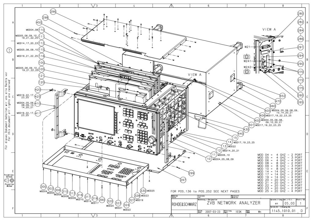
173
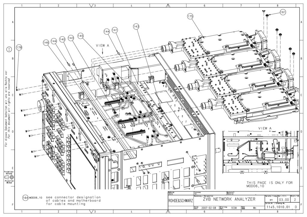
174
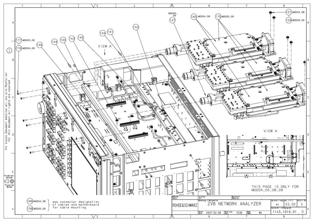
175
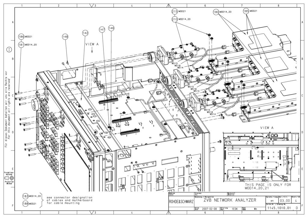
176
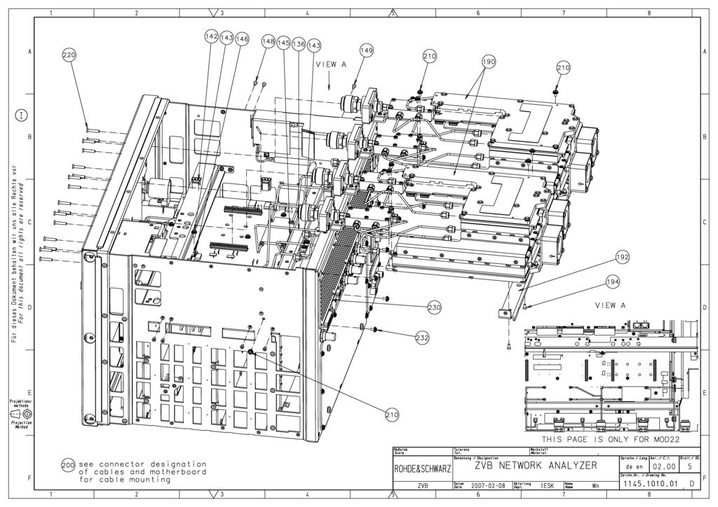
177
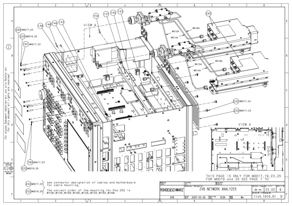
178
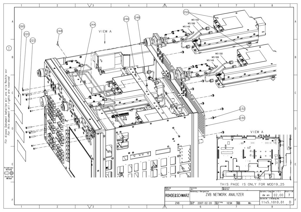
179
180
181
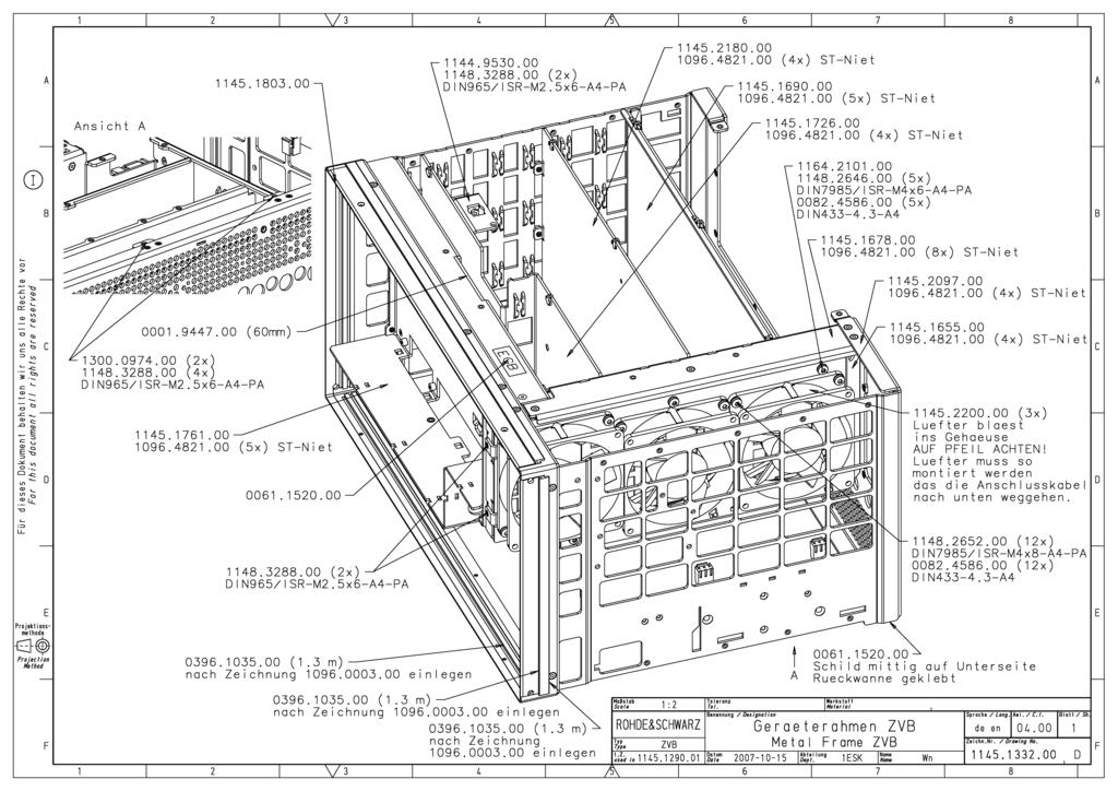
182
R&S ZVA-Zxx Millimeter-Wave Converters Specifications
 R&S ZVA-Zxx Millimeter-Wave Converters Specifications Data Sheet Version 19.00 CONTENTS Definitions... 3 General information... 4 Specifications... 5 Test port... 5 Source input (RF IN)... 5 Local oscillator
R&S ZVA-Zxx Millimeter-Wave Converters Specifications
 ZVA-Zxx_dat-sw_en_5214.2033.22_umschlag.indd 1 Data Sheet 13.00 Test & Measurement R&S ZVA-Zxx Millimeter-Wave Converters Specifications 28.01.2013 15:08:06 CONTENTS General information... 3 Definitions...
R&S ZVA110 Vector Network Analyzer Specifications
 ZVA110_dat-sw_en_5214-4813-22_cover.indd 1 Data Sheet 04.00 Test & Measurement R&S ZVA110 Vector Network Analyzer Specifications 15.11.2013 14:42:28 CONTENTS Definitions... 3 Specifications... 4 Overview...
Spectrum Analyzer 1.6 GHz 3 GHz R&S HMS-X
 HMS-X_bro_de-en_3607-0181-3X_v0200.indd 1 Product Brochure 02.00 Test & Measurement Spectrum Analyzer 1.6 GHz 3 GHz R&S HMS-X 15.03.2016 15:24:06 1 Basic Unit + 3 Options Key facts Frequency range: 100
Advanced Test Equipment Rentals ATEC (2832)
") E stablished 1981 Advanced Test Equipment Rentals www.atecorp.com 800-404-ATEC (2832) Technical Datasheet Scalar Network Analyzer Model 8003-10 MHz to 40 GHz The Giga-tronics Model 8003 Precision Scalar
E stablished 1981 Advanced Test Equipment Rentals www.atecorp.com 800-404-ATEC (2832) Technical Datasheet Scalar Network Analyzer Model 8003-10 MHz to 40 GHz The Giga-tronics Model 8003 Precision Scalar
Extension kit for R&S Vector Network Analysers
 NM300 Data Sheet September 2012 Extension kit for R&S Vector Network Analysers Characterisation of Nonlinear RF/HF Components in Time and Frequency domain Extension kit for R&S Vector Network Analysers
Basic RF Amplifier Measurements using the R&S ZNB Vector Network Analyzer and SMARTerCal. Application Note
 Basic RF Amplifier Measurements using a R&S ZNB Analyzer and SMARTerCal Mark Bailey 2013-03-05, 1ES, Version 1.0 Basic RF Amplifier Measurements using the R&S ZNB Vector Network Analyzer and SMARTerCal.
RF Level Test System +20 dbm to 130 dbm
 NRVD Power Meter optional Therm. Sensor A B Power: >-15 dbm DUT (Signal Generator, Communication Tester) 1 MHz - 3.5/6 GHz +20 dbm... -130 dbm Diode Sensor Z4 Power: -15 to -40 dbm 6 db Power =< -40 dbm
Model 7330 Signal Source Analyzer Dedicated Phase Noise Test System V1.02
 Model 7330 Signal Source Analyzer Dedicated Phase Noise Test System V1.02 A fully integrated high-performance cross-correlation signal source analyzer from 5 MHz to 33+ GHz Key Features Complete broadband
R&S ZND Vector Network Analyzer Specifications
 R&S ZND Vector Network Analyzer Specifications year Test & Measurement Data Sheet 02.01 CONTENTS Definitions... 3 Measurement range... 4 Measurement speed... 5 Measurement accuracy... 7 Effective system
R&S FS-Z60/75/90/110 Harmonic Mixers for the R&S FSP/FSU/ FSQ/FSUP/FSV
 Test & Measurement Data Sheet 04.00 R&S FS-Z60/75/90/110 Harmonic Mixers for the R&S FSP/FSU/ FSQ/FSUP/FSV R&S FS-Z60/75/ 90/110 Harmonic Mixers At a glance The R&S FS-Z60/-Z75/-Z90/-Z110 harmonic mixers
R&S ZNBT Vector Network Analyzer Specifications
 R&S ZNBT Vector Network Analyzer Specifications year Data Sheet Version 05.02 CONTENTS Definitions... 3 Measurement range... 4 Measurement speed... 6 Measurement accuracy of the R&S ZNBT8... 8 Measurement
Spectrum Analyzer 1.6 GHz 3 GHz HMS-X
 Spectrum Analyzer 1.6 GHz 3 GHz 1 Basic Unit + 3 Options Your Spectrum Analyzer Key facts Frequency range: 100 khz to 1.6 GHz/3 GHz* 1 Spectral purity greater than -100 dbc/hz (at 100 khz) SWEEP from 20
R&S ETH Handheld TV Analyzer Portable DVB-T/H signal analysis up to 3.6/8 GHz
 R&S ETH Handheld TV Analyzer Portable DVB-T/H signal analysis up to 3.6/8 GHz Broadcast Product Brochure 02.00 R&S ETH Handheld TV Analyzer At a glance The R&S ETH handheld TV analyzer was specially designed
Vector Network Analyzer TTR503A/TTR506A USB Vector Network Analyzer Preliminary Datasheet. Subject to change.
 Vector Network Analyzer TTR503A/TTR506A USB Vector Network Analyzer Preliminary Datasheet. Subject to change. Applications Academic/Education Design, development and manufacturing of passive and active
R&S FPC1000 Spectrum Analyzer Specifications
 R&S FPC1000 Spectrum Analyzer Specifications year Data Sheet Version 01.00 CONTENTS Definitions... 3 Specifications... 4 Frequency... 4 Sweep time... 4 Bandwidth... 4 Level... 5 Trigger functions... 6
Assembly Level Service Guide
 Assembly Level Service Guide This guide describes how to service the Agilent 53150A, 53151A, and 53152A Microwave Frequency Counters. The information in this guide applies to instruments having the number
Calibrating the CMD Output Level for BER
 Ref Lvl -32 dbm -40-50 Marker 1 [T1] -35.50 dbm 5.000000 ms RBW 300 khz RF Att 0 db VBW 3 MHz SWT 5 ms Unit dbm 1 SUMMARY [T1] A RMS AVG -85.86 dbm SGL TRG -60-70 1RM -80 EXT -90-100 -110-120 -130 T1 T2
R&S FSV-K40 Phase Noise Measurement Application Specifications
 FSV-K40_dat-sw_en_5213-9705-22_cover.indd 1 Data Sheet 02.00 Test & Measurement R&S FSV-K40 Phase Noise Measurement Application Specifications 06.10.2014 14:51:49 CONTENTS Specifications... 3 Ordering
FCPM-6000RC. Mini-Circuits P.O. Box , Brooklyn, NY (718)
") USB / Ethernet Integrated Frequency Counter & Power Meter 50Ω -30 dbm to +20 dbm, 1 MHz to 6000 MHz The Big Deal Automatically synchronized power & frequency measurements USB and Ethernet control Includes
USB / Ethernet Integrated Frequency Counter & Power Meter 50Ω -30 dbm to +20 dbm, 1 MHz to 6000 MHz The Big Deal Automatically synchronized power & frequency measurements USB and Ethernet control Includes
7000 Series Signal Source Analyzer & Dedicated Phase Noise Test System
 7000 Series Signal Source Analyzer & Dedicated Phase Noise Test System A fully integrated high-performance cross-correlation signal source analyzer with platforms from 5MHz to 7GHz, 26GHz, and 40GHz Key
R3267/3273 Spectrum Analyzers
 R3267/3273 Spectrum Analyzers For 3rd-Generation Mobile Communications Present Digital Communication standards (W-CDMA, PDC, PHS, IS-136, GSM, DECT, cdmaone ) R3267/3273 New communication technologies
R&S FSMR Measuring Receiver Specifications
 Test & Measurement Data Sheet 09.00 R&S FSMR Measuring Receiver Specifications CONTENTS Specifications... 3 Frequency...3 Measuring receiver... 3 Frequency counter...3 RF power...4 RF level (tuned receiver)...5
R&S ZN-Z151/-Z152/-Z153 Calibration Unit Specifications
 ZN-Z151_152_153_dat-sw_en_3607-0881-22_v0100_cover.indd 1 Data Sheet 01.00 Test & Measurement R&S ZN-Z151/-Z152/-Z153 Calibration Unit Specifications 07.10.2014 11:35:47 CONTENTS Definitions... 3 Measurement
R&S ZNL Vector Network Analyzer Specifications
 R&S ZNL Vector Network Analyzer Specifications year Data Sheet Version 01.00 CONTENTS Definitions... 3 Specifications... 4 Measurement range... 4 Measurement speed... 5 Measurement accuracy... 6 Effective
R&S HA-Z24E External Preamplifier 1 GHz to 85 GHz Specifications
 R&S HA-Z24E External Preamplifier 1 GHz to 85 GHz Specifications Data Sheet Version 01.01 Definitions General Product data applies under the following conditions: Three hours storage at ambient temperature
R&S ZN-Z103 Calibration Unit Specifications. Data Sheet V02.01
 R&S ZN-Z103 Calibration Unit Specifications Data Sheet V02.01 CONTENTS Definitions... 3 Measurement range... 5 Effective system data... 5 General data... 6 Ordering information... 7 2 Rohde & Schwarz R&S
R&S ZN-Z154 Calibration Unit Specifications
 ZN-Z154_dat-sw_en_3607-0481-22_v0101_cover.indd 1 Data Sheet 01.01 Test & Measurement R&S ZN-Z154 Calibration Unit Specifications 25.06.2014 10:27:09 CONTENTS Definitions... 3 Measurement range... 4 Effective
R&S RT-Zxx High-Bandwidth Probes Specifications
 R&S RT-Zxx High-Bandwidth Probes Specifications Test & Measurement Data Sheet 14.00 CONTENTS Definitions... 3 Probe/oscilloscope chart... 4 R&S RT-ZZ80 transmission line probe... 5 R&S RT-ZS10/-ZS10E/-ZS20/-ZS30
USB Smart Power Sensor
 50Ω -30 dbm to +20 dbm, 1 MHz to 8000 MHz The Big Deal Fast measurement speed, 10 msec USB HID device compatible with 32/64 Bit operating systems Includes Measurement Application GUI (Graphical User Interface)
Application Note DT-AN-2115B-1. DTA-2115B Verification of Specifations
 DTA-2115B Verification of Specifations APPLICATION NOTE January 2018 Table of Contents 1. Introduction... 3 General Description of the DTA-2115B... 3 Purpose of this Application Note... 3 2. Measurements...
R&S ZVB Vector Network Analyzer High measurement speed up to 20 GHz with two or four test ports
 Test & Measurement Established 1981 Advanced Test Equipment Rentals www.atecorp.com 800-404-ATEC (2832) Product Brochure 07.00 R&S ZVB Vector Network Analyzer High measurement speed up to 20 GHz with two
The high-end network analyzers from Rohde & Schwarz now include an option for pulse profile measurements plus, the new R&S ZVA 40 covers the
 GENERAL PURPOSE 44 448 The high-end network analyzers from Rohde & Schwarz now include an option for pulse profile measurements plus, the new R&S ZVA 4 covers the frequency range up to 4 GHz. News from
R&S FPC-Z10 Teaching Kit Getting Started
 R&S FPC-Z10 Teaching Kit Getting Started 1178843602 Getting Started Version 03 This manual describes the following products: R&S FPC-Z10 Teaching Kit (1328.7338.02) 2018 Rohde & Schwarz GmbH & Co. KG Mühldorfstr.
Agilent 5345A Universal Counter, 500 MHz
 Agilent 5345A Universal Counter, 500 MHz Data Sheet Product Specifications Input Specifications (pulse and CW mode) 5356C Frequency Range 1.5-40 GHz Sensitivity (0-50 deg. C): 0.4-1.5 GHz -- 1.5-12.4 GHz
R&S ZN-Z85 Switch Matrix Specifications
 R&S ZN-Z85 Switch Matrix Specifications Data Sheet Version 01.02 CONTENTS Definitions... 3 Block diagrams... 4 Specifications... 5 General features... 5 Performance data... 5 Remote control... 5 Switching
SMS3000X Series Spectrum Analyzer
 Data Sheet SMS3000X Series Spectrum Analyzer SMS3032X SMS3021X General Description SMS3000X series spectrum analyzer has a frequency range from 9 khz up to 2.1 GHz/3.2 GHz, it is light weight and small
Application Note DT-AN DTU-315 Verification of Specifications
 DTU-315 Verification of Specifications APPLICATION NOTE January 2018 Table of Contents 1. Introduction... 3 General Description of the DTU-315... 3 Purpose of this Application Note... 3 2. Measurements...
USB-TG124A Tracking Generator User Manual
 USB-TG124A Tracking Generator User Manual Signal Hound USB-TG124A User Manual 2017, Signal Hound, Inc. 35707 NE 86th Ave La Center, WA 98629 USA Phone 360.263.5006 Fax 360.263.5007 This information is
R&S SMBV-Z1 Reference Frequency Converter Specifications
 Test & Measurement Data Sheet 01.01 R&S SMBV-Z1 Reference Frequency Converter Specifications Version 01.01, July 2011 CONTENTS Definitions... 3 Introduction... 4 Specifications... 4 Input signal...4 Output
R&S HF907DC SHF Downconverter Specifications
 Radiomonitoring & Radiolocation Data Sheet 01.03 R&S HF907DC SHF Downconverter Specifications CONTENTS Definitions... 3 Specifications... 4 Frequency conversion... 4 Input and output properties... 4 Rechargeable
R&S FSW-K160RE 160 MHz Real-Time Measurement Application Specifications
 FSW-K160RE_dat-sw_en_3607-1759-22_v0200_cover.indd 1 Data Sheet 02.00 Test & Measurement R&S FSW-K160RE 160 MHz Real-Time Measurement Application Specifications 06.04.2016 17:16:27 CONTENTS Definitions...
R&S FSW-B512R Real-Time Spectrum Analyzer 512 MHz Specifications
 R&S FSW-B512R Real-Time Spectrum Analyzer 512 MHz Specifications Data Sheet Version 02.00 CONTENTS Definitions... 3 Specifications... 4 Level... 5 Result display... 6 Trigger... 7 Ordering information...
R&S RT-Zxx High-Voltage and Current Probes Specifications
 R&S RT-Zxx High-Voltage and Current Probes Specifications Test & Measurement Data Sheet 14.00 CONTENTS Definitions... 3 Probe/oscilloscope chart... 4 R&S RT-ZH10/-ZH11 high-voltage probes... 5 R&S RT-ZD01
HP 71910A and 71910P Wide Bandwidth Receiver Technical Specifications
 HP 71910A and 71910P Wide Bandwidth Receiver Technical Specifications 100 Hz to 26.5 GHz The HP 71910A/P is a receiver for monitoring signals from 100 Hz to 26.5 GHz. It provides a cost effective combination
Measurement Method for Determining the Equivalent Reflection Coefficient of Directional Couplers and Power Splitters
 Products: R&S ZVM, R&S ZVK Measurement Method for Determining the Equivalent Reflection Coefficient of Directional Couplers and Power Splitters A measurement method presented by John R. Juroshek (NIST)
R&S Cable Rider ZPH Cable and Antenna Analyzer Specifications
 R&S Cable Rider ZPH Cable and Antenna Analyzer Specifications year Data Sheet Version 01.01 CONTENTS Definitions... 3 Specifications of the R&S Cable Rider ZPH Cable and Antenna Analyzer... 4 Frequency...
Bluetooth Tester CBT. Specifications. Specifications. Version January 2006
 Specifications Version 03.00 Bluetooth Tester CBT January 2006 Specifications CONTENTS UNIT SPECIFICATIONS...3 TIMEBASE TCXO...3 REFERENCE FREQUENCY INPUT...3 RF GENERATOR...3 RF ANALYZER...5 Power meter
VNA Master Model MS203xA
 Maintenance Manual VNA Master Model MS203xA Vector Network Analyzer Anritsu Company 490 Jarvis Drive Morgan Hill, CA 95037-2809 USA P/N: 10580-00168 Revision: B Printed: December 2008 Copyright 2008 Anritsu
Microwave Counter, Power Meter and DVM in One Portable Package
 Agilent 53140 Series Microwave Counter, Power Meter and DVM in One Portable Package Product Overview Everything you need for the installation and maintenance of microwave links: A choice of frequency counter
R&S AMU-Z7 Analog I/Q Combiner Technical Information
 R&S AMU-Z7 Analog I/Q Combiner Technical Information 1415.7335.92 01 Test & Measurement Technical Information 2009 Rohde & Schwarz GmbH & Co. KG 81671 Munich, Germany Printed in Germany Subject to change
Analyze Frequency Response (Bode Plots) with R&S Oscilloscopes Application Note
 with R&S Oscilloscopes Application Note") Analyze Frequency Response (Bode Plots) with R&S Oscilloscopes Application Note Products: R&S RTO2002 R&S RTO2004 R&S RTO2012 R&S RTO2014 R&S RTO2022 R&S RTO2024 R&S RTO2044 R&S RTO2064 This application
Analyze Frequency Response (Bode Plots) with R&S Oscilloscopes Application Note Products: R&S RTO2002 R&S RTO2004 R&S RTO2012 R&S RTO2014 R&S RTO2022 R&S RTO2024 R&S RTO2044 R&S RTO2064 This application
R&S SMF100A Microwave Signal Generator Specifications
 R&S SMF100A Microwave Signal Generator Specifications Test & Measurement Data Sheet 04.00 Specifications Specifications apply under the following conditions: 30 minutes warm-up time at ambient temperature,
RS Pro SPECTRUM ANALYZER SSA3000X SERIES
 Product Datasheet ENGLISH Stock No: 1236443 (RSSA3021X) 1236444 (RSSA3032X) RS Pro SPECTRUM ANALYZER SSA3000X SERIES Features and Benefits RSSA3032X XX RSSA3021X All-Digital IFTechnology Frequency Range
R&S ZV-Z81 Multiport Test Set, models.05/.09/.29 Specifications
 ZV-Z81_models5_9_29_dat-sw_en_5213-6864-22_Cover.indd 1 Data Sheet 04.01 Test & Measurement R&S ZV-Z81 Multiport Test Set, models.05/.09/.29 Specifications 17.04.2013 12:47:27 CONTENTS Definitions... 3
Modular Block Converter Systems
 Modular Block Converter Systems The Modular Block Converter System eliminates system downtime and maximizes ease of repair by providing fully modular systems for up conversion or down conversion. Critical
Full-featured CW Microwave Counters for Field, Factory or Lab
 Full-featured CW Microwave Counters for Field, Factory or Lab Product Overview Agilent 53150A 20 GHz Counter Agilent 53151A 26.5 GHz Counter 46 GHz Counter High performance microwave counters: at home,
PIM Master. Maintenance Manual
 Maintenance Manual PIM Master MW8208A, MW8209A, MW8219A Passive InterModulation Analyzer MW8208A: 869 MHz to 894 MHz MW8209A: 925 MHz to 960 MHz MW8219A: 1930 MHz to 1930 MHz and 2110 MHz to 2155 MHz Anritsu
Agilent 8560 E-Series Spectrum Analyzers
 Agilent 8560 E-Series Spectrum Analyzers Data Sheet 8560E 30 Hz to 2.9 GHz 8561E 30 Hz to 6.5 GHz 8562E 30 Hz to 13.2 GHz 8563E 30 Hz to 26.5 GHz 8564E 30 Hz to 40 GHz 8565E 30 Hz to 50 GHz 8565E SPECTRUM
R&S Cable Rider ZPH Cable and Antenna Analyzer Specifications
 R&S Cable Rider ZPH Cable and Antenna Analyzer Specifications year Data Sheet Version 02.02 CONTENTS Definitions... 3 Specifications... 4 Frequency... 4 Measurements... 4 Channel power meter (R&S ZPH-K19
Spectrum Master Models MS2723B and MS2724B
 Maintenance Manual Spectrum Master Models MS2723B and MS2724B Handheld Spectrum Analyzer Anritsu Company 490 Jarvis Drive Morgan Hill, CA 95037-2809 USA Part Number: 10580-00165 Revision: D Published:
News from Rohde&Schwarz Number 195 (2008/I)
") BROADCASTING TV analyzers 45120-2 48 R&S ETL TV Analyzer The all-purpose instrument for all major digital and analog TV standards Transmitter production, installation, and service require measuring equipment
BROADCASTING TV analyzers 45120-2 48 R&S ETL TV Analyzer The all-purpose instrument for all major digital and analog TV standards Transmitter production, installation, and service require measuring equipment
Test and Communications Antennas for the R&S TS8991 OTA Performance Test System Specifications
 Test and Communications Antennas for the R&S TS8991 OTA Performance Test System Specifications R&S TC-TA18 cross-polarized Vivaldi test antenna, R&S TC-CA6 linear-polarized communications antenna Data
Transcom Instruments. Product Brochure TRANSCOM INSTRUMENTS. Product Brochure. 1
 TRANSCOM INSTRUMENTS Product Brochure Transcom Instruments Product Brochure www.transcomwireless.com 1 T5000 Series Bench-top Vector Network Analyzer Overview T5000 Series Bench-top Vector Network Analyzer
MTP200B WLAN / BT LE Tester
 www.tescom.co.kr MTP200B WLAN / BT LE Tester Introduction Tescom s MTP200B is a non-signaling test-based WLAN or BT LE (Low Energy) tester. As one-body equipment incorporating both Signal Generator and
JD725A Cable and Antenna Analyzer - Dual Port
 COMMUNICATIONS TEST & MEASUREMENT SOLUTIONS JD725A Cable and Antenna Analyzer - Dual Port Key Features Portable and lightweight handheld instrument Built-in wireless frequency bands as well as the most
Keysight FieldFox Microwave Analyzers
 Quick Reference Guide Contents Keysight FieldFox Microwave Analyzers Do you have everything?... 1 The Power Button and LED... 1 Battery Usage... 2 Measure Return Loss (CAT Mode)... 3 Measure 1-Port Cable
LadyBug Technologies, LLC LB5908A True-RMS Power Sensor
 LadyBug Technologies, LLC LB5908A True-RMS Power Sensor LB5908ARev8 LadyBug Technologies www.ladybug-tech.com Telephone: 707-546-1050 Page 1 LB5908A Data Sheet Key PowerSensor+ TM Specifications Frequency
Measurements on GSM Base Stations According to Rec
 Measurements on GSM Base Stations According to Rec. 11.20 Application Note 1EF23_0L Subject to change 10 September 96, Josef Wolf / Roland Minihold Products: FSE incl. Option FSE-B7 1 Introduction The
R&S EDS300 DME/Pulse Analyzer Specifications
 R&S EDS300 DME/Pulse Analyzer Specifications year Data Sheet Version 04.01 CONTENTS Definitions... 3 Specifications... 4 Frequency... 4 Level... 4 DME signal analysis... 4 TACAN signal analysis (R&S EDS-K1
USB Smart Power Sensor
 USB Smart Power Sensor 50Ω -30 dbm to +20 dbm, 1MHz to 6000 MHz The Big Deal Low cost USB HID device compatible with 32 Bit operating system Includes Measurement Application GUI (Graphical User Interface)
Agilent 4-Port PNA-L Microwave Network Analyzer
 Agilent 4-Port PNA-L Microwave Network Analyzer N523A 3 khz to 13.5, 2 GHz Data Sheet Note: Specification information in this document is also available within the PNA-L network analyzer s internal Help
Noise Detector ND-1 Operating Manual
 Noise Detector ND-1 Operating Manual SPECTRADYNAMICS, INC 1849 Cherry St. Unit 2 Louisville, CO 80027 Phone: (303) 665-1852 Fax: (303) 604-6088 Table of Contents ND-1 Description...... 3 Safety and Preparation
Frequency. Range. HP 83751A/B: 2 GHz to 20 GHz HP 83752A/B: 10 MHz to 20 GHz. Standard 10 MHz timebase: f10 ppm
 Frequency Range HP 83751A/B: 2 GHz to 20 GHz HP 83752A/B: 10 MHz to 20 GHz Timebase Stability Standard 10 MHz timebase: f10 ppm High stability timebase (Option le5): Accuracy = Calibration &Aging rate
Software. Documentation. Test Equipment
 CALIBRATION PROCEDURE NI PXIe-5694 This document contains the verification and adjustment procedures for the National Instruments PXIe-5694 IF conditioning module (NI 5694). Refer to ni.com/calibration
Inmarsat Downconverter Narrowband Downconverter
 Visit us at www.w ork-microw ave.de Inmarsat Downconverter Narrowband Downconverter L-Band to 70/140 MHz S-Band to 725 MHz 140 MHz to 15 MHz Single Conversion Dual Channel Converters also available. These
R&S RSC Step Attenuator Where precise signal levels count
 Test & Measurement Product Brochure 01.00 Step Attenuator Where precise signal levels count Step Attenuator At a glance The is a switchable, mechanical step attenuator. It is available in various models
Signal Stability Analyser
 Signal Stability Analyser o Real Time Phase or Frequency Display o Real Time Data, Allan Variance and Phase Noise Plots o 1MHz to 65MHz medium resolution (12.5ps) o 5MHz and 10MHz high resolution (50fs)
R&S SMB100A RF and Microwave Signal Generator Specifications
 R&S SMB100A RF and Microwave Signal Generator Specifications year Test & Measurement Data Sheet 09.00 CONTENTS Definitions... 3 Specifications... 4 Hardware and software option concept... 4 RF performance...
R&S ZND Vector Network Analyzer Basic, solid-performance network analysis
 R&S ZND Vector Network Analyzer Basic, solid-performance network analysis Product Brochure Version 02.00 year ZND_bro_en_3607-0381-12_v0200.indd 1 12.12.2017 19:33:33 R&S ZND Vector Network Analyzer At
R&S FSV-K8 Bluetooth /EDR Measurement Application Specifications
 R&S FSV-K8 Bluetooth /EDR Measurement Application Specifications Test & Measurement Data Sheet 01.01 CONTENTS R&S FSV-K8 Bluetooth /EDR measurement application... 3 Frequency...3 Measurement parameters...3
R&S FSV-K73 3G FDD UE (UL) Measurements incl. HSUPA Specifications
 Measurements incl. HSUPA Specifications") FSV-K73_dat-sw_en_5214-0976-22_cover.indd 1 Data Sheet 02.00 Test & Measurement R&S FSV-K73 3G FDD UE (UL) Measurements incl. HSUPA Specifications 01.08.2013 17:36:27 CONTENTS Specifications... 3 Frequency...
FSV-K73_dat-sw_en_5214-0976-22_cover.indd 1 Data Sheet 02.00 Test & Measurement R&S FSV-K73 3G FDD UE (UL) Measurements incl. HSUPA Specifications 01.08.2013 17:36:27 CONTENTS Specifications... 3 Frequency...
ENGINEERING COMMITTEE Interface Practices Subcommittee AMERICAN NATIONAL STANDARD ANSI/SCTE Mainline Pin (plug) Connector Return Loss
 Connector Return Loss") ENGINEERING COMMITTEE Interface Practices Subcommittee AMERICAN NATIONAL STANDARD ANSI/SCTE 125 2007 Mainline Pin (plug) Connector Return Loss NOTICE The Society of Cable Telecommunications Engineers (SCTE)
ENGINEERING COMMITTEE Interface Practices Subcommittee AMERICAN NATIONAL STANDARD ANSI/SCTE 125 2007 Mainline Pin (plug) Connector Return Loss NOTICE The Society of Cable Telecommunications Engineers (SCTE)
R&S ZNBT Vector Network Analyzer Network analysis with up to 24 test ports
 R&S ZNBT Vector Network Analyzer Network analysis with up to 24 test ports ZNBT_bro_en_3606-9727-12_v0300.indd 1 Product Brochure 03.00 Test & Measurement year 11.07.2016 14:59:23 R&S ZNBT Vector Network
Agilent E5100A Network Analyzer
 Agilent E5100A Network Analyzer Data Sheet These specifications are the performance standards or limits against which the instrument is tested. When shipped from the factory, the E5100A meets the specifications
ESU EMI Test Receiver Specifications
 ESU EMI Test Receiver Specifications Test & Measurement Data Sheet 02.01 CONTE NT S BASE UNIT... 3 FREQUENCY... 3 RECEIVER SCAN... 4 SWEEP... 4 PRESELECTION... 4 IF AND RESOLUTION BANDWIDTHS... 5 LEVEL...
 Over 5000 VXI cards and mainframes in stock. 1000's of pieces of Test Equipment in stock. Looking for Test Equipment? Visit us on the web at www.recycledequipment.com Recycled Equipment buys, sells, and
Agilent CSA Spectrum Analyzer N1996A
 Agilent CSA Spectrum Analyzer N1996A Demonstration Guide Introduction This step-by-step demo guide will help you explore the unprecedented value of the Agilent CSA spectrum analyzer for meeting your design,
Transcom Instruments. Product Brochure TRANSCOM INSTRUMENTS. Product Brochure
 TRANSCOM INSTRUMENTS Product Brochure Transcom Instruments Product Brochure TRANSCOM T5000 Series Bench-top Vector Network Analyzer Overview T5000 Series bench-top vector network analyzer offers the high
E4416A/E4417A EPM-P Series Power Meters and E-Series E9320 Peak and Average Power Sensors DATA SHEET
 E4416A/E4417A EPM-P Series Power Meters and E-Series E9320 Peak and Average Power Sensors DATA SHEET EPM-P Power Meter Specifications Specifications describe the instrument s warranted performance and
Test and Communications Antennas for the R&S TS8991 OTA Performance Test System Specifications
 Test and Communications Antennas for the R&S TS8991 OTA Performance Test System Specifications R&S TC-TA18 cross-polarized Vivaldi test antenna, R&S TC-TA85CP cross-polarized Vivaldi test antenna, R&S
Spectrum Analyzers. 2399A 9 khz to 3 GHz Spectrum Analyzer.
 Spectrum Analyzers 2399A 9 khz to 3 GHz Spectrum Analyzer A spectrum analyzer with outstanding performance and a user friendly visual interface simplifying many complex measurements 9 khz to 3 GHz fully
MS2718B, MS2719B Economy Spectrum Analyzer
 Maintenance Manual MS2718B, MS2719B Economy Spectrum Analyzer MS2718B: MS2719B: 9 khz to 13 GHz 9 khz to 20 GHz Anritsu Company 490 Jarvis Drive Morgan Hill, CA 95037-2809 USA Part Number: 10580-00198
VectorStar ME7838E 2-Port Broadband/Banded Millimeter-Wave System
 Quick Start Guide VectorStar ME7838E 2-Port Broadband/Banded Millimeter-Wave System High Performance Modular Broadband/Banded Millimeter-Wave Vector Network Analyzer (VNA) Measurement System, 70 khz to
NS-3 RF Noise Source Operation Manual
 RF Noise Source Operation Manual Version 2.04 June 3, 2016 SPECIFICATIONS Frequency... Maximum output level... Output flatness... (at max output level) Impedance... Displayed level... Repeatability...
R&S SGMA Product Family Compact fast reliable
 Test & Measurement Product Brochure 5. R&S SGMA Product Family Compact fast reliable R&S SGS1A SGMA RF Source, R&S SGU1A SGMA Upconverter R&S SGMA Product Family At a glance The R&S SGS1A is an RF source
Synthesized Clock Generator
 Synthesized Clock Generator CG635 DC to 2.05 GHz low-jitter clock generator Clocks from DC to 2.05 GHz Random jitter
R&S FSMR Measuring Receiver All-in-one calibration of signal generators and attenuators
 R&S FSMR Measuring Receiver All-in-one calibration of signal generators and attenuators Product Brochure Version 04.00 year FSMR_Bro_en_0758-2319-12_v0400.indd 1 19.05.2017 14:41:56 R&S FSMR Measuring
R&S DST200 RF Diagnostic Chamber Specifications
 DST200_dat-sw_en_5214-3600-22_v0500_cover.indd 1 Data Sheet 05.00 Test & Measurement R&S DST200 RF Diagnostic Chamber Specifications 08.04.2016 15:35:59 CONTENTS Definitions... 3 Base unit... 4 R&S DST200
R&S RT-Zxx Standard Probes Specifications
 R&S RT-Zxx Standard Probes Specifications Test & Measurement Data Sheet 16.00 CONTENTS Definitions... 3 Probe/oscilloscope chart... 4 R&S RT-ZP03 passive probe... 5 R&S RT-ZP05(S) passive probe... 8 R&S