Application Note - TechComplete Test Productivity Pack. POP Reporting
|
|
|
- Nigel McCoy
- 5 years ago
- Views:
Transcription
1 Application Note - TechComplete Test Productivity Pack Page 1 of 61
2 Table of Contents Introduction... 5 POP Test Configuration... 6 Executing POP Tests on DSAM... 7 Accessing POP Reports... 9 POP Reports Settings POP Limits Section a) Editable POP Limits Non Licensed Version b) Editable POP Limits Licensed Version System Information Section Reports Configuration Licensed Version a) Signal Quality Units b) Display Audio Level or Video Audio Delta Level c) Change Six Month Deviation Formula d) POP Reports Required and Matching Fields How to Create 24 Hour POP Reports Search for test files Configure data for 24 hour POP reports Non Licensed Version Configure data for 24 hour POP reports Licensed Version CSV Export CSV Import a) Disable Import of System Information/Measurement File Data from CSV File b) Steps to Import CSV File Delete Channels View 24 hour POP report a) Non Licensed Version b) Licensed Version Save 24 hour POP Report Licensed Version Hour POP Report Features Licensed Version Search 24 hour POP Report View 24 hour POP report Regenerate 24 hour POP report Page 2 of 61
3 4. View measurement files used in 24 hour POP report Upload attachments Download attachments Delete attachments Save report as HTML or XLS Export Familyware files Export Report bundle Import 24 hour POP report Delete 24 hour POP report How to Create System Summary Report Licensed Version How to Create Six Month Report Licensed Version Search for 24 hour POP reports Ignore Channel Frequency and Type Errors during 6 Month Deviation Calculation Month POP Report Features Licensed Version Search 6 month Report View 6 month report View 6 month Summary report View 24 hour reports Upload attachments Download attachments Delete attachments Save report as HTML or XLS Export Report bundle Import 6 month POP report Delete 6 month POP report APPENDIX A. TPP Test Reporting System POP Report Details When Report Name is considered unique? When does a 24 hour POP report fails? Conditions to generate a 6 month POP report Licensed Version When does a 6 month POP report fail? Licensed Version Page 3 of 61
4 Configuring the POP Report POP Default Limits APPENDIX B. Summary of FCC Proof of Performance Test Overview of FCC Proof of Performance Test Requirements Who must run the tests? When do the tests need to be run? How many channels need to be tested? How are the test channels selected? How many test sites do we need? Where, in the system, are the tests conducted? Are there specified procedures for each test? Where do we send the test results? What happens if we don't pass? Where do I go for more information on Proof Testing? Page 4 of 61
5 Introduction The term Proof of Performance tests may have different interpretations depending on your geographic locality. In North America, Proof of Performance tests can tie directly to testing mandated by the Federal Communications Commission (FCC); however, in other localities Proof of Performance test may simply refer to having the ability to run test over various times and physical constraints such as weather and/or temperature. The DSAM meter can perform Proof of Performance tests immediately or over any set of time intervals that you desire. This is particularly useful when you are running the 24- Hour test required by the FCC in the US and by other international governing bodies. With release of TPP v4.6, following are enhancements to POP reports feature: I. Digital measurements are added to 24 hour POP reports. II. Limits present in the DSAM POP measurement files are not used in the TPP POP Reports. POP limits configured in the TPP POP Reports section are used for creating those reports. III. Following tests are added to 24 hour POP reports Adjacent Visual Signal Level Minimum Visual Signal Level Aural Carrier Level Analog Delta Video Digital Delta Video IV. Following are newly added POP tests/features that are available only with the purchase of POP license: Analog Measurement Tests in 24 hour POP report Visual Carrier Frequency Aural Carrier Frequency Offset Carrier to Noise Hum In-Channel Frequency Response Carrier Triple Beat (CTB) Carrier Second Order (CSO) Digital Measurement Tests in 24 hour POP report Visual Carrier Frequency MER Pre-BER Post-BER In-Channel Frequency Response Group Delay Gain Compression 6 Month Deviation Test Editing POP FCC limits Page 5 of 61

6 Searching 24 hour and 6 month POP reports. Configuring data for 24 hour POP report. Deleting channels from 24 hour POP report. Saving 24 hour POP reports Regeneration of 24 hour POP reports. System Summary Report Six month report Six month summary report Exporting POP reports along with attachments and importing them into another TPP Server It is a fact that all cable systems need to be able to consistently check measurements in their network during various times and over a wide temperature range. The DSAM together with the Test Productivity Pack (TPP) provides a seamless way for operators to conduct Proof of Performance. This Application Note will provide key step-by-step instructions on setting up TPP to work in conjunction with the DSAM to deliver the Proof of Performance functionality. POP Test Configuration Proof of Performance testing is configured using TPP. A typical configuration for performing Proof of Performance test is shown below. 1. Select the Location File Icon from the main menu. 2. Create a new Proof Location File by double-clicking on the default Proof of Performance file. Page 6 of 61


7 3. Customize Proof of Performance initial values and/or Field Names 4. Deploy / Save the location in the same fashion as done for Channel or Limit Plans 5. Synchronize selected meters with the appropriate TPP Server Executing POP Tests on DSAM Key steps in running the Proof of Performance test on the DSAM include the following: 1. Press the AutoTest button on the DSAM 2. Scroll down to and select proof of performance Page 7 of 61


8 3. Configure the Proof of Performance Test Channel Plan, Limit Plan, Filename to save to, Ambient Temp, etc. Name entered in Filename to save to field will become folder name for the proof of performance files. 4. Configure Proof of Performance Test Scheduling via Scheduled Soft Key Meter shuts down until time of Auto Test and wakes itself Input start time, interval, date, etc... 4 sessions over a 24 hour period 5. Input location data (i.e. Location, Location Type, Area, Trunk, AMP ID ) Page 8 of 61


9 6. Start Proof of Performance Test 7. Monitor progress and Review Results. 8. Results are saved in an appropriately named folder as entered in Filename to save to field in step3. 9. Sync the DSAM to the TPP Server to transfer test results to the server Accessing POP Reports Links to access POP reports are available from two places: 1) In left panel, under Test Reporting System section as shown below: Page 9 of 61


10 2) Click on Test Reporting System in left panel. In right panel, under Test Reporting System menu. POP Reports Settings In left panel, click on POP reports link. In right panel, in POP reports page, click on POP REPORTS SETTINGS link. POP reports settings page allows user to set system information mapping, audio level or video audio delta level information to be displayed in 24 hour POP report and edit POP FCC limits that are used in validating POP tests. Click on Save button at the top or bottom of page to save changes to any edited fields. This page has following sections: 1. POP Limits Section This section contains limits that are used in determining the Pass/Fail status for various POP tests. After editing the limit values, click on Save button at the top or bottom of page to save changes. To restore default FCC limits, click on Set Limit Defaults button at the bottom of page followed by click on Save button to save changes. a) Editable POP Limits Non Licensed Version Below are the editable limits for non licensed POP version and TPP applies modified limits while performing 24 hour POP tests. Page 10 of 61

11 b) Editable POP Limits Licensed Version Below limit values can be changed and TPP applies modified limits while performing 24 hour or 6 month POP tests. Page 11 of 61

12 Page 12 of 61
 Enter location field names from above file that contains System, Test Point, Test Point Location, Headend/Hub and Municipality information respectively.")

13 2. System Information Section a) Create and Deploy location file to DSAM as explained in section POP Test Configuration. b) Enter location field names from above file that contains System, Test Point, Test Point Location, Headend/Hub and Municipality information respectively. When the above fields are set, TPP automatically pulls Report Name, System, Test Point, Test Point Location, Headend/Hub and Municipality from location information in a measurement file and displays this information in 24 hour POP report. If the above fields are blank then TPP will not display this information in 24 hour POP report. 3. Reports Configuration Licensed Version a) Signal Quality Units This setting is POP-report-specific site-wide configuration for all POP reports data entry and display fields. The data will be presented in selected QAM signal quality unit in POP report configuration page and other reports only upon pressing save button at the end. b) Display Audio Level or Video Audio Delta Level In below drop down, select Audio Level or Video Audio Delta Level, if you like to have Audio Level or Video Audio Delta Level displayed in 24 hour POP report. Page 13 of 61

14 c) Change Six Month Deviation Formula There are two formulas that are available which determine six month deviation calculation using 8 POP test files. Select an option and click on Save button to save changes. d) POP Reports Required and Matching Fields Configure Required Fields for 24 hour POP Report Creation By default, the required non configurable fields for 24 hour POP report creation are System and Test Point. During 24 hour POP report creation, along with the above fields Test Point Location, Headend/Hub and Municipality are also displayed. This section allows user to configure whether Test Point Location, Page 14 of 61

15 Headend/Hub and Municipality are required or non-required fields during creation of a 24 hour report. If the above highlighted fields in red are set to true, then TPP will not allow user to create or save 24 hour POP report if any of these fields are left as blank. Configure Matching Fields for 6 Month POP Report Creation For 6 Month POP report creation, by default, the required non configurable matching fields between two selected 24 hour POP reports are System and Test Point. Along with the above fields, TPP allows user to configure whether Test Point Location, Headend/Hub and Municipality required being same across selected 24 hour POP Reports during 6 month POP report creation. If the above highlighted fields in red are set to true, then TPP will not allow user to create a 6 Month POP report if any of these fields that are set to true do not match across selected 24 hour POP reports. How to Create 24 Hour POP Reports 1. Search for test files There are two ways to get list of test files from the database that can be used to generate 24 hour POP Reports: Click on TPP test files link in left panel. Click on show test files link or any other link under Search for test files by section followed by find button press will display list files page. Based on search this page can display all types of measurement files like Video Auto Test, Home Certification, and POP etc. Choose 4 files for your 24 hour POP report and click on 24 icon to generate your report Page 15 of 61

16 Snapshot of TPP test files page: In left panel, click on POP reports link. Below are the screen shots of POP reports page without license and with license. Snapshot of POP reports page Non Licensed Version Page 16 of 61


17 Snapshot of POP reports page Licensed Version In POP reports page, select proof of performance tests option and click on find button. This will display POP test files page. Choose 4 files for your 24 hour POP report and click on 24 icon to generate your report. Page 17 of 61

18 Snapshot of POP test files page: 2. Configure data for 24 hour POP reports Non Licensed Version Snapshot of POP report configuration page Non Licensed Version 3. Configure data for 24 hour POP reports Licensed Version Fill in all the required * fields. Report Name, System, Test Point, Test Point Location, Headend/Hub and Municipality are automatically filled in if System Information is set as explained in POP Reports Settings System Information section. If mapped keys as set in POP reports settings page are Page 18 of 61
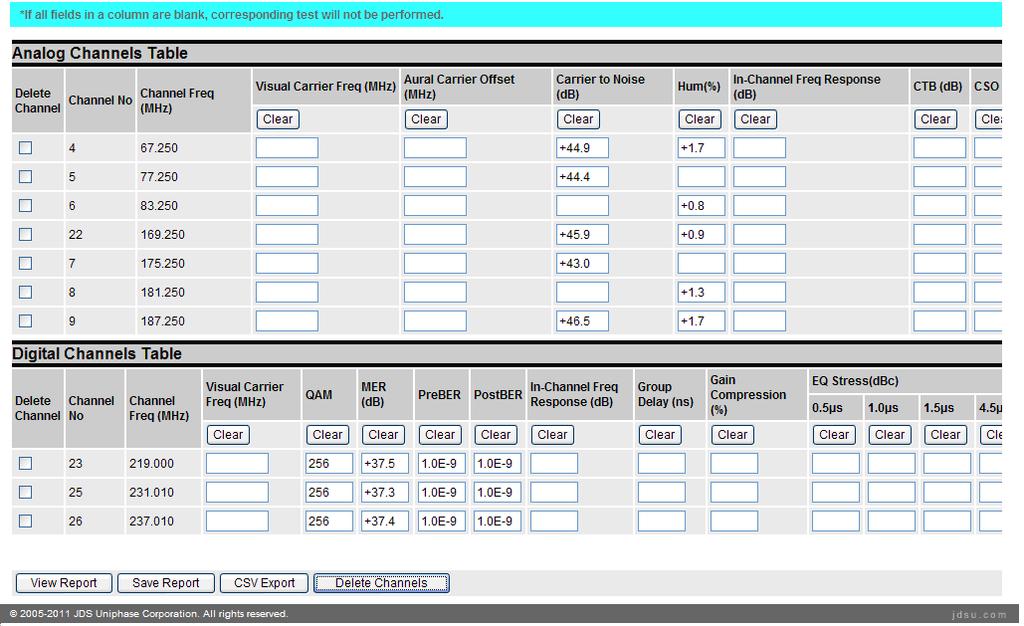
19 not found then the above mentioned fields will be empty and user has to manually fill in information. If Test Point key as set in POP reports settings page is not found in Location File, then TPP will set the value of Test Point field to work folder name in which the first file in Import Data from File drop down is saved. Report Name, System, Test Point, Test Point Location, Headend/Hub and Municipality are always displayed using location file from first measurement file in Import Data from File drop down. Selecting a different file in Import Data from File drop down will not update the system information. Active Analog and Active Digital channels fields are populated from channel plan used. Selecting a file in Import Data from File drop down will update the counts. Bandwidth is calculated using channel plan from first measurement file as shown in import data from file drop down as follows: Bandwidth = (Highest active channel frequency in channel plan Lowest Frequency)-1.25f; Minimum Required Test Channels is a calculated field by applying FCC standards using bandwidth information as explained below: a minimum of four (4) channels plus one additional channel for every 100 MHz, or fraction thereof, of cable distribution system upper frequency limit (e.g. 5 channels for cable system upper frequency limit of 101 to 216 MHz; 6 channels for cable television systems with a cable distribution system upper frequency limit of MHz; 7 channels for cable television systems with a cable distribution upper frequency to 300 to 400 MHz, etc.). In measurement file section, you can change the temperature of any file. If temperature field for a file is 0 then TPP will use temperature information from measurement file if available. Converter selection determines the limits that are used during Aural Carrier Level test. For baseband, V/A should be between Minimum Baseband Video/Aural Carrier Level Delta and Maximum Baseband Video/Aural Carrier Level Delta. For none and standard, V/A should be between Minimum Standard Video/Aural Carrier Level Delta and Maximum Standard Video/Aural Carrier Level Delta Value selected in Cable System drop down determines the limit values that are used in performing Carrier Triple Beat (CTB) and Carrier Second Order (CSO). If value selected is Non Coherent then limit value of field Minimum Standard Coherent Disturbance as set in POP reports settings page is used for CTB and CSO test. If value selected is Coherent then limit value of field Minimum Baseband Coherent Disturbance as set in POP reports settings page is used for CTB and CSO test. By default information from first measurement file will be populated into Analog and Digital Channels Table. Changing the value in import data from file will fill the analog channels and digital channels tables with data from the selected measurement file. In Analog Channel Table or Digital Channels Table, if all rows in a column for a test are empty then that test is not performed. Fill in data in columns for each test that needs to be performed. The number of channels with data filled in for each test should be >= count Page 19 of 61
20 displayed in Minimum Required Test Channels field, otherwise respective test will be failed. To clear data in a column under Analog Channels Table and Digital Channels Table, click on clear button. POP report configuration page screen shot Licensed Version Page 20 of 61

21 Page 21 of 61

22 4. CSV Export This feature allows exporting the page data to CSV file in a format supported by TPP for CSV import. Data can be exported to CSV file as explained below: Click on CSV Export button as shown below in red box. If the browser is IE, it will show a File Download dialog as shown below. Click on Save button. Page 22 of 61


23 Enter file name in the dialog as shown below and click on Save button. All data in page is saved to CSV file. Open file using Microsoft Excel, edit data and import file using CSV Import functionality as explained below. 5. CSV Import The CSV file that contains measurement file data to be imported to TPP should be in the supported template format. This template can be obtained by following steps in CSV Export section. On successful CSV file import, TPP will overwrite data in all fields in page with data from the file. Page 23 of 61

24 a) Disable Import of System Information/Measurement File Data from CSV File Disabling import of system information from CSV file will not import data for Report Name, System, Test Point, Test Point Location, Headend/Hub, Municipality, Bandwidth, Converter, Cable System and Comments fields. Disabling import of measurement file data from CSV will not import temperature for measurement file. Follow these steps to disable import of system information or temperature for measurement file from CSV file: Stop TPP server by stopping FDM250Service using windows services panel. To disable import of system information from CSV file, add the following property to configuration.properties, often installed at C:\Program Files\Acterna FDM-250\cfg. CSV_IMPORT_POP_SYSTEM_INFO= false To disable import of temperature for measurement file from CSV file, add the following property to configuration.properties, often installed at C:\Program Files\Acterna FDM-250\cfg. CSV_IMPORT_POP_MEASFILE_INFO = false Save changes and start TPP server by starting FDM250Service using windows services panel. b) Steps to Import CSV File Follow these steps to import CSV file to TPP: Click on Browse button as shown in below screen shot: In fie upload dialog, navigate to location of CSV file, select the file and click on Open button as shown in below screen shot: Page 24 of 61

25 Click on CSV Import button as shown in below screen shot: Click Ok button on the pop up as shown below: Page 25 of 61

26 If there are any errors displayed at the top of the page, repeat all the above steps after fixing CSV file. If you do not see any error messages at the top, verify all the data in page and click on View Report or Save Report button to view or save report. 6. Delete Channels To delete Analog and Digital channels from 24 hour POP report, select delete check box against the required channel number and click on Delete Channels button at the bottom of page. Click on View Report or Save Report button to view or save report. Once the channels are deleted and report is saved then deleted channels will never appear in report. If you want deleted channels to appear in report again, please follow Regenerate 24 hour POP report section under 24 Hour POP Report Features section. 7. View 24 hour POP report In POP report configuration page, click on View Report button, 24 hour POP report opens in a new browser window/tab. Page 26 of 61


27 a) Non Licensed Version Page 27 of 61

28 You may also Print / Export results. Export options include EXCEL & a FamilyWare POP Report batch zip file. Snapshot of POP export zip file Snapshot of 24 hour POP report in excel Page 28 of 61


29 b) Licensed Version 24 hour POP report screen shot Licensed Version Page 29 of 61

30 Page 30 of 61


31 24 hour POP report screen shot continued Licensed Version Page 31 of 61
, click on Save Report button.")

32 24 hour POP report screen shot continued - Licensed Version You may also Print / Excel Export results. 8. Save 24 hour POP Report Licensed Version In POP reports page (refer to POP report configuration page screen shot for bullet 3), click on Save Report button. Report is saved to database and 24 hour details page is displayed. 24 Hour POP Report Features Licensed Version 1. Search 24 hour POP Report a) In left panel, click on POP reports link. Select 24 hour POP reports option. If you know the name of the report, enter in name field otherwise leave the name field empty. You can search on date range the report is created by selecting Date Range option and setting start and end dates. If you do not remember report creation date, select Any Date option. Click on Find button. Snapshot of POP reports page b) List page with 24 hour POP reports is displayed. You can sort on columns by clicking on column headers. Page 32 of 61

33 c) Click on report name link or select check box against a 24 hour report and click on display icon as shown in below screen shot. d) 24 Hour POP Report Details page as shown below is displayed. Details page for 24 hour POP report allows user to view report, regenerate 24 hour POP report, upload, download and delete attachments, save 24 hour POP report as HTML and excel. This page also allows user to export 24 hour POP report bundle and import the same into another server. This report bundle includes any uploaded attachments along with measurement files that are used in creating 24 hour POP report. Page 33 of 61

34 Snapshot of 24 Hour POP Report Details page 2. View 24 hour POP report To view report, click on View 24 Hour and Miscellaneous Reports button. 3. Regenerate 24 hour POP report This feature allows regeneration of 24 hour POP report if there are any data entry mistakes or if analog channels or digital channels measurements for respective tests need to be pulled from different measurement file during data configuration for 24 hour POP report. Repeat steps in bullet 1 to select a 24 hour report. In 24 Hour POP Report Details page, click on Regenerate 24 Hour and Miscellaneous Reports button. POP report configuration page as shown in below screen shot is displayed: Page 34 of 61

35 Edit all the required information. To pull data from a different measurement file into Analog and Digital Channels table, select a measurement file in Import Data from file drop down. If a file is already selected in Import Data from File drop down, then selecting blank in drop down will clear data in Analog and Digital Channels Table. Click on View Report button to view report. All data changes are not saved until Save Report button is clicked. 4. View measurement files used in 24 hour POP report Repeat steps in bullet 1 to select a 24 hour report. To view all measurement files used in report, click on Measurement Files text in measurement files section. This will open all measurement files used in report in a different Page 35 of 61

36 window. This gives the option to print measurement files too. To view each file individually, click on file name in Measurement Files section. 5. Upload attachments Repeat steps in bullet 1 to select a 24 hour report. To upload any files that are used in creating a 24 hour report, in attachments section, click on browse button. Choose file and click on open button. Click on upload button. The maximum allowed combined size of all attachments is 16MB. 6. Download attachments Repeat steps in bullet 1 to select a 24 hour report. To download attachments, in Attachments section, select a radio button next to attachment name and click on download button. 7. Delete attachments Repeat steps in bullet 1 to select a 24 hour report. To delete any attachment, select a radio button next to attachment name and click on delete button. Page 36 of 61
37 8. Save report as HTML or XLS Repeat steps in bullet 1 to select a 24 hour report. To save report as HTML or XLS click on Save as HTML or Save HTML as XLS buttons. 9. Export Familyware files Repeat steps in bullet 1 to select a 24 hour report. To generate files needed for uploading to POP Familyware software, click on POP Export button. This will prompt you to save the zip file that contains the required text files. 10. Export Report bundle This feature allows user to export 24 hour POP report from a TPP server and import report into another TPP Server. Repeat steps in bullet 1 to select a 24 hour report. Click on Export Report Bundle button. A pop dialog will ask you to save the file. Click on save button to save the file. All attachments that are uploaded along with measurement files that are used in report creation are exported with this bundle. 11. Import 24 hour POP report This feature allows user to import 24 hour POP report that was previously exported from a different TPP Server. a) In left panel, click on POP reports link. In POP reports page, click on Browse button. Page 37 of 61
38 b) In file dialog, navigate to the location where the report bundle is present. The report bundle will have 24hour_JDSUPOP_zip as extension. Select the bundle and click on open button. c) Click on upload button. If there are no errors, report will be imported to TPP. Page 38 of 61

39 12. Delete 24 hour POP report This feature allows user to delete 24 hour POP reports from TPP. Repeat steps a, b and c in bullet 1 to view 24 hour POP reports list page. Select checkboxes for each 24 hour POP report that you like to delete. Click on X icon as shown in below snapshot. A 24 hour POP report is not deleted if it s in use by a six month report. Snapshot explaining 24 hour POP reports delete functionality: How to Create System Summary Report Licensed Version System Summary Report is the aggregation of data from 24 hour POP reports generated for test points under a system. This report is generated only if all the selected 24 hour POP reports are under same system. In left panel, click on POP reports link. In POP reports page, select 24 hour POP reports option and click on Find button. List of 24 hour POP reports is displayed. Select check boxes for 24 hour POP reports that are generated for Test Points under same system. Click on System Summary Report button. Page 39 of 61


40 Fill information in fields in System Summary page. In the above, value for Required Minimum Test Points is automatically calculated on filling in Subscriber Count. Click on View System Report button to view report. Below is the screen shot of sample System Report. Page 40 of 61

41 Snapshot of Sample System Report Page 41 of 61

42 How to Create Six Month Report Licensed Version 1. Search for 24 hour POP reports In left panel, click on POP reports link. In POP reports page, select 24 hour POP reports option and click on Find button. List of 24 hour POP reports are displayed. Select check boxes for exactly two 24 hour POP reports and click on 6 icon. Note: - A 6 Month Configuration page is displayed only when System, Test Point and the required matching fields as set in POP Reports Settings page are same cross selected 24 hour POP Reports. While performing matching between two selected 24 hour POP reports, space is removed from the values and then compared. For Ex: - if system name in first 24 hour POP report is Beech Grove and system name in second 24 hour POP report is BeechGrove they are considered equal as the space is removed from the system names before checking if they are equal. The same is done before comparing all required system information fields between two selected 24 hour POP reports. In 6 Month Configuration page, enter report name and click on Save Report. Report is saved to database and 6 month details page is displayed. Page 42 of 61

43 Page 43 of 61

44 Page 44 of 61

45 Page 45 of 61

46 You may also Print / Excel Export report. Page 46 of 61


47 2. Ignore Channel Frequency and Type Errors during 6 Month Deviation Calculation Between two selected 24 hour POP reports, if there are any channels that differ in frequency or type then following button is displayed as shown below: Click on the above highlighted button. The report is refreshed and frequency and channel type errors are ignored during 6 month deviation test. Below is the screen shot of 6 Month POP report when frequency and type errors are ignored: The 6 Month Deviation Result column will display status as ignored for channels where frequency or type errors are ignored. If you do not want to ignore frequency and channel type errors, click on the Do not Ignore Frequency and Channel Type Errors during Six Month Deviation Result Calculation button as shown below: Page 47 of 61

48 The report is refreshed without ignoring frequency or channel type errors during 6 Month deviation status calculation. Once the required action is done, please click on Save Report button otherwise report is not saved. 6 Month POP Report Features Licensed Version 1. Search 6 month Report a) In left panel, click on POP reports link. Select 6 month POP reports option. If you know the name of the report, enter in name field otherwise leave the name field empty. You can search on date range the report is created by selecting Date Range option and setting start and end dates for you search. If you do not remember report creation date select Any Date option. Click on Find button. b) List page with 6 month POP reports is displayed. You can sort on columns by clicking on column headers. c) Click on report name link or select check box against a 6 month report and click on display icon as shown in below screen shot. Page 48 of 61

49 d) 6 Month Report Details page as shown below is displayed. 2. View 6 month report Repeat steps in bullet 1 to select a 6 month report. Click on View Report button to view report. 3. View 6 month Summary report Repeat steps in bullet 1 to select a 6 month report. Click on View Just 6 Month Summary Report button to view report. Below is the screen shot of sample six month summary report: Page 49 of 61

50 Page 50 of 61
51 4. View 24 hour reports Repeat steps in bullet 1 to select a 6 month report. Click on + icon for a 24 hour report. 24 hour report details page is displayed. Refer to section 24 Hour POP Report Features for more details. 5. Upload attachments Repeat steps in bullet 1 to select a 6 month report. To upload any files that are used in creating a 24 hour report, in attachments section, click on browse button. Choose file and click on open button. Click on upload button. The maximum allowed combined size of all 6 month report attachments is 48 MB which includes 16MB total size per 24 hour POP report attachments and 16MB total size for 6 Month report attachments. 6. Download attachments Repeat steps in bullet 1 to select a 6 month report. To download attachments, in Attachments section, select a radio button next to attachment name and click on download button. 7. Delete attachments Repeat steps in bullet 1 to select a 6 month report. To delete any attachment, select a radio button next to attachment name and click on delete button. Page 51 of 61

52 8. Save report as HTML or XLS Repeat steps in bullet 1 to select a 6 month report. To save report as HTML or XLS click on Save as HTML or Save HTML as XLS buttons. 9. Export Report bundle This feature allows user to export 6 month POP report from a TPP server and import report into another TPP Server. Repeat steps in bullet 1 to select a 6 month report. Click on Export Report Bundle button. A pop dialog will ask you to save the file. Click on save button to save the file. The exported bundle includes attachments that are uploaded for 6 month report along with two 24 hour POP report bundles with their attachments and measurement files that are used in report creation. 10. Import 6 month POP report This feature allows user to import 6 month POP report that was previously exported from a different TPP Server. a) In left panel, click on POP reports link. In POP reports page, click on Browse button. Page 52 of 61
53 b) In file dialog, navigate to the location where the report bundle is present. The report bundle will have 6month_JDSUPOP_zip as extension. Select the bundle and click on open button. c) Click on upload button. If there are no errors, report will be imported to TPP. Page 53 of 61

54 11. Delete 6 month POP report This feature allows user to delete 6 month POP reports from TPP. Repeat steps a, b and c in bullet 1 to view 6 month POP reports list page. Select checkboxes for each 6 month POP report that you like to delete. Click on X icon as shown in below snapshot: Snapshot explaining 6 month POP reports delete functionality: Page 54 of 61
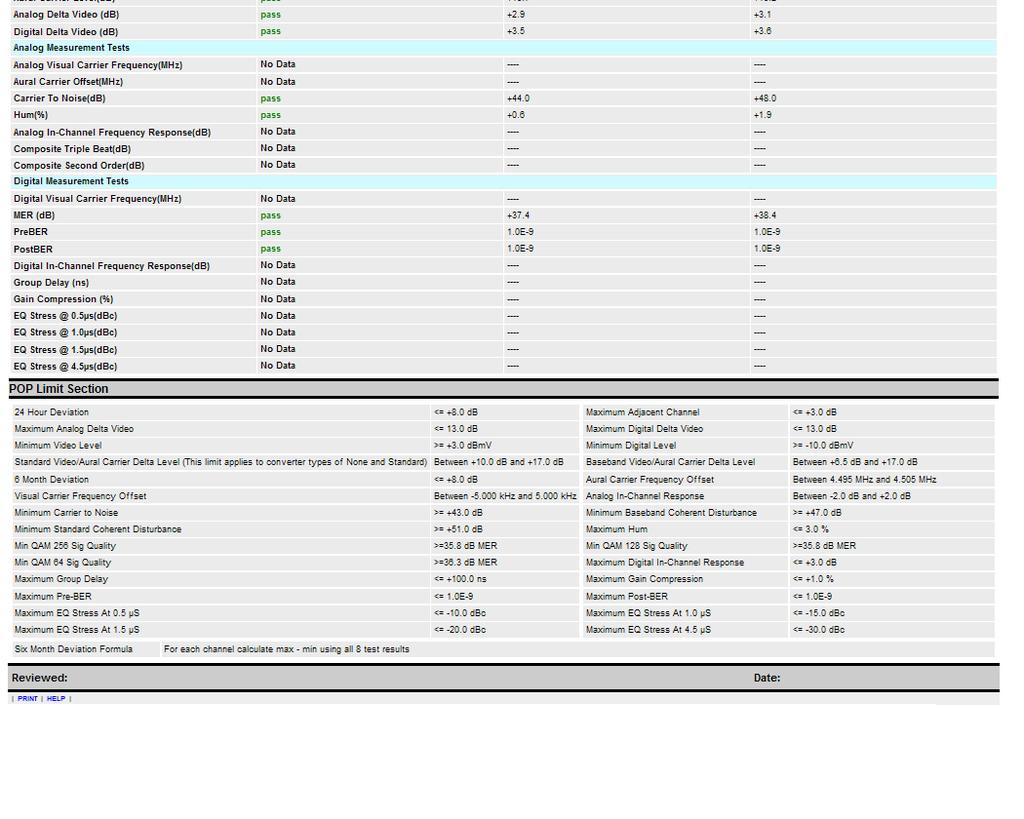
55 APPENDIX A. TPP Test Reporting System POP Report Details When Report Name is considered unique? A Report Name is considered unique when following set of fields is unique Report Name, System, Test Point, Test Point Location, Headend/Hub and Municipality Note: - Test Point Location, Headend/Hub and Municipality can be empty. When does a 24 hour POP report fails? The overall status of 24 hour POP report is fail if either of 24 hour POP tests or Analog Measurement Test (applicable only for licensed version) or Digital Measurement Test (applicable only for licensed version) status is fail. 24 hour POP report status is fail if: 1. Channel type or frequency does not match among measurements 2. Missing channels in measurement files 3. 4 measurement files are not used 4. If measurements are not with in 6, 12, and 18 hours from the 1st test (plus or minus 1 hour). 5. If 24 hour deviation is not with in 24 Hour Deviation Limit as set in POP Reports Settings page. The default value is 8dB. 6. If Adjacent Visual Signal Level a.k.a Adjacent Channel is not with in Maximum Adjacent Channel limit as set in POP Reports Settings page. The default value is 3dB. This 3dB is applicable for both analog and digital channels. 7. If there are pair of analog (TV or Dual) channels which happen to be with in 6 MHz frequency separation and there is no adjacent channel data measured. 8. If Minimum Visual Signal Level is less than Minimum Video Level Limit as set in POP Reports Settings page. The default value is 3dBmV. 9. If Minimum Digital Level is less than Minimum digital Level Limit as set in POP Reports Settings page. The default value is -10dBmV. 10. If converter type is none or standard and Aural Carrier Level a.k.a V/A Level is not in between MINIMUM STANNDARD VIDEO/AURAL CARRIER LEVEL DELTA and MAXIMUM STANDARD VIDEO/AURAL CARRIER LEVEL DELTA. If converter type is baseband and V/A level is not in between MINIMUM BASEBAND VIDEO/AURAL CARRIER LEVEL DELTA and MAXIMUM BASEBAND VIDEO/AURAL CARRIER LEVEL DELTA. For converter type of standard or none, default min and max are 10dB and 17 db respectively. For converter type of baseband, default min and max are 6.5dB and 17 db respectively. 11. If Analog Delta Video is not with in Maximum Analog Delta Video Limit. Maximum Analog Delta Video Limit is calculated as follows using Maximum Analog Delta Video and Analog Delta Video Offset as set in POP reports settings page: If bandwidth > 300MHz then Page 55 of 61
56 Maximum Analog Delta Video Limit = Maximum Analog Delta Video + Analog Delta Video Offset for each additional 100MHz above 300 MHz. else Maximum Analog Delta Video Limit = Maximum Analog Delta Video The default limit and offset are 10dB and 1dB respectively. 12. If Digital Delta Video is not with in Maximum Digital Delta Video Limit. Maximum Digital Delta Video Limit is calculated as follows using Maximum Digital Delta Video anddigital Delta Video Offset as set in POP reports settings page: If bandwidth > 300MHz then Maximum Digital Delta Video Limit = Maximum Digital Delta Video + Digital Delta Video Offset for each additional 100MHz above 300 MHz. else Maximum Digital Delta Video Limit = Maximum Digital Delta Video Note: - If there are no analog channels i.e. only digital channels are present or if there exists analog channels that do not fall in 6 MHz separation with analog channel next to it, and if there is no Adjacent Visual Signal data for any channel then Adjacent Visual Signal status is displayed as No data and it is not taken into consideration for the overall report status calculation. Analog Measurement Test status (applicable only for licensed version) is fail: 1. If Visual Carrier Frequency is not with in Minimum Visual Carrier Frequency Offset and Maximum Carrier Frequency Offset from channel frequency as set in POP reports settings page. The default values are -5 to 5 KHz respectively. 2. If Aural Carrier Frequency Offset is not with in Minimum aural Carrier Frequency Offset and Maximum Aural Carrier Frequency Offset as set in POP reports settings page. The default values are to MHz respectively. 3. If Carrier to Noise is less than Minimum Carrier to Noise as set in POP reports settings page. The default value is 43 db. 4. If Hum is greater than Maximum Hum as set in POP reports settings page. The default value is 3%. 5. If In-Channel Frequency Response is not with in Minimum Analog In-Channel Response and Maximum Analog In-Channel Response. The default values are -2 db to +2 db respectively. 6. If cable system is Non Coherent and Carrier Triple Beat (CTB) is less than Minimum Standard Coherent Disturbance as set in POP reports settings page. The default value is 51 db. If cable system is coherent and Carrier Triple Beat is less than Minimum Baseband Coherent Disturbance as set in POP reports settings page. The default value is 47 db. 7. If cable system is Non Coherent and Carrier Second Order (CSO) is less than Minimum Standard Coherent Disturbance as set in POP reports settings page. The default value is 51 Page 56 of 61
57 db. If cable system is coherent and Carrier Second Order is less than Minimum Baseband Coherent Disturbance as set in POP reports settings page. The default value is 47 db. 8. If any of the above tests does not test minimum required analog channels. Note: -Minimum required test channels criteria is applied only if data is available for the channels for the respective test. Digital Measurement Test status (applicable only for licensed version) is fail: 1. If Visual Carrier Frequency is not with in Minimum Visual Carrier Frequency Offset and Maximum Carrier Frequency Offset from channel frequency as set in POP reports settings page. The default values are -5 to 5 KHz respectively. 2. If MER is less than Minimum QAM 256 Signal Quality for 256 QAM type or less than Minimum QAM 128 Signal Quality for 128 or Minimum QAM 64 Signal Quality for 64 as set in POP reports settings page. The defaults are 36 for each QAM type. 3. If QAM type is not either of 64 or 128 or If PreBER is greater than Maximum PreBER as set in POP reports settings page. The default value is 1.00-E9. 5. If PostBER is greater than Maximum PostBER as set in POP reports settings page. The default value is 1.00E-9 6. If In-Channel Frequency Response for digital channel is greater than Maximum Digital In- Channel Response. The default value is 3 db. 7. If Group Delay is greater than Maximum Group Delay as set in POP reports settings page. The default value is 100 ns. 8. If Gain Compression is greater than Maximum Gain Compression as set in POP reports settings page. The default value is 1.0 %. 9. If EQ 0.5 is greater than Maximum EQ 0.5 as set in POP reports settings page. The default value is -10 dbc. 10. If EQ 1.0 is greater than Maximum EQ 1.0 as set in POP reports settings page. The default value is -15 dbc. 11. If EQ 1.5 is greater than Maximum EQ 1.5 as set in POP reports settings page. The default value is -20 dbc. 12. If EQ 4.5 is greater than Maximum EQ 4.5 as set in POP reports settings page. The default value is -30 dbc. Note: -Minimum required test channels criteria is not applied for digital channel tests. Conditions to generate a 6 month POP report Licensed Version A six month report is generated under the following conditions: 1. If measurements in each of 24 hour tests are with in 6, 12 and 18 hours from the 1 st test (plus or minus) 1 hour. 2. If System and Test Point along with required matching fields as set in POP reports settings page are same across selected 24 hour reports. Page 57 of 61
58 3. If selected two 24 hour reports are 5-7 months a part. The 5-7 month interval is calculated between last test date of first 24 hour report and first test date of second 24 hour report. Note: - TPP does not validate whether the reports were generated in months of Jan/Feb and Jul/Aug. When does a 6 month POP report fail? Licensed Version The overall status of six month report is fail 1. If the total number of files from two 24 hour reports is less than 8 2. If status of any of 24 hour report is fail or if six month deviation > 8 db 3. If channel line up does not match across all 8 test results 4. If channel frequencies or channel types do not match between selected 24 hour POP reports and frequency or type errors not ignored during 6 month report creation. 5. If System or Test Point information do not match across selected 24 hour POP reports. Configuring the POP Report To configure Signal Level Units: From the TPP Web Application, select system preferences from the left panel. Under the global system preferences section, select measurements.. Select the desired Signal Level Units value and press Save. To configure a custom report header: From the TPP Web Application, select system preferences from the left panel. Under the global system preferences section, select report header. Check the use custom report header box. Enter the HTML for the Address and Custom sections. Via the file system, install a new custom icon and press Save. POP Default Limits Below table lists the default POP limit values used by TPP. Limit Name Limit Value Comment 24 Hour Deviation 8 db Maximum Adjacent Channel 3 db Maximum Analog Delta Video 10 db Analog Delta Video Offset 1 db For bandwidth > 300 MHz, Offset will be added to Maximum Analog Delta Video limit for each additional 100 MHz above 300 MHz Maximum Digital Delta Video 10 db Digital Delta Video Offset 1 db For bandwidth > 300 MHz, Offset will be added to Maximum Analog Delta Video limit for each additional 100 MHz above 300 MHz Minimum Video Level 3 dbmv Video level for analog channels. Page 58 of 61
59 Minimum Digital Level -10 dbmv Video level for digital/docsis channels. Minimum Standard Video/Aural Carrier Level Delta 10 db This limit applies to converter types of None and Standard Maximum Standard Video/Aural Carrier Level Delta 17 db This limit applies to converter types of None and Standard Minimum Baseband Video/Aural Carrier 6.5 db Level Delta Maximum Baseband Video/Aural Carrier 17 db Level Delta 6 Month Deviation 8 db Minimum Aural Carrier Frequency Offset MHz Maximum Aural Carrier Frequency Offset MHz Minimum Visual Carrier Frequency Offset -5 KHz Maximum Visual Carrier Frequency Offset +5 KHz Minimum Analog In-Channel Frequency -2 db Response Maximum Analog In-Channel Frequency +2 db Response Minimum Carrier to Noise 43 db Minimum Baseband Coherent Disturbance 47 db Minimum Standard Coherent Disturbance 51 db Maximum Hum 3 % Min QAM 256 Sig Quality 35.8 db MER Min QAM 128 Sig Quality 35.8 db MER Min QAM 64 Sig Quality 36.3 db MER Maximum Digital In-Channel Response 3 db Maximum Group Delay 100 ns Maximum Gain Compression 1 % Maximum Pre-BER 1.0E-9 Maximum Post-BER 1.0E-9 Maximum EQ Stress At 0.5 µs -10 dbc Maximum EQ Stress At 1.0 µs -15 dbc Maximum EQ Stress At 1.5 µs -20 dbc Maximum EQ Stress At 4.5 µs -30 dbc Page 59 of 61
60 APPENDIX B. Summary of FCC Proof of Performance Test Overview of FCC Proof of Performance Test Requirements For details of the Proof of Performance test requirements, refer to the Code of Federal Regulations (CFR) 47, part 76. This book is available from the US Government Printing Office, Mail Stop: SSOP, Washington, DC Many cities in the US have US Government Printing Office stores that sell Government publications directly to the public. Who must run the tests? All systems with 1000 or more subscribers. Smaller systems are required to comply with the Cumulative Leakage Index requirements (including quarterly measurements) but are not normally required to demonstrate proof of performance of the other technical standards. The technical standards are expected to be met by all systems -- but small systems don't need to prove it. When do the tests need to be run? Most tests need to be conducted "at least twice each calendar year (at intervals not to exceed seven months)". The "24 hour" tests "shall be measured and recorded, along with the date and time of the measurement, once every six hours (at intervals of not less than five hours nor more than seven hours after the previous measurement), to include the warmest and the coldest times, during a 24 hour period in January or February and in July or August". The 24 hour test is the only one required during those particular months. The color tests (Chrominance to Luminance Delay Inequality, Differential Gain, and Differential Phase), need to be conducted at least triennially (once every three years). How many channels need to be tested? Many tests are required on all "NTSC or similar video channels" of the system. Other tests are required "a minimum of four (4) channels plus one additional channel for every 100 MHz, or fraction thereof, of cable distribution system upper frequency limit (e.g. 5 channels for cable system upper frequency limit of 101 to 216 MHz; 6 channels for cable television systems with a cable distribution system upper frequency limit of MHz; 7 channels for cable television systems with a cable distribution upper frequency to 300 to 400 MHz, etc.)." All channels are required to meet all of the technical standards. However, for certain of the technical standards, you only need to demonstrate "proof of performance" on a sampling of the channels... How are the test channels selected? "The channels selected must be representative of all the channels within the cable television system." Generally, systems select channels from across the system's spectrum. How many test sites do we need? For systems from 1000 to 12,500 subscribers, tests "... shall include measurements taken at six (6) widely separated points. However, within each cable system, one additional test point shall be added for every additional 12,500 subscribers or fraction thereof (e.g., 7 test points if 12,501 to 25,000 subscribers, etc.). " Also, there must be at least one test point "for each portion of the cable system served by a technically integrated microwave hub". Note that this does not mean a test point for each fiber node. Page 60 of 61
61 Where, in the system, are the tests conducted? Test points "shall be balanced to represent all geographic areas served by the cable system. At least onethird of the test points shall be representative of subscriber terminals most distant from the system input and from each microwave receiver (if microwave transmissions are employed), in terms of cable length". Measurements may be made at convenient monitoring points in the system so long as the data reflects system performance for nearby subscribers. Some measurements (visual signal level and 24 hour tests) are required to be measured "at the end of a 30 meter (100 foot) cable drop that is connected to the subscriber tap,..." Usually, all tests in the field are conducted at the end of a 100 foot drop cable. The 100 foot drop cable simulates typical drops provide to homes. For tests at the output of a set-top converter, connect the converter to the end of the drop cable. Are there specified procedures for each test? In general, no. However, good engineering practices are to be used for all tests. For some measurements, the rules refer to documents such as the "NCTA Recommended Practices for Measurements on Cable Television Systems, 2nd edition, November 1989". A review of that document is an excellent starting point. Of course, measurement equipment and techniques are continually evolving. There is a lot of test equipment available today that make the tests much easier than some of the procedures described in the NCTA documents. Before you decide to use any procedure, you should of course, have a thorough understanding of the test requirements and the algorithms used by your test gear. Do not blindly trust automated test gear simply because it provides "numbers"! Where do we send the test results? Unless told otherwise by the FCC or your franchise authorities, you simply keep the data on file for at least five years. The test data is required to be made available to the FCC or local franchise authorities upon request. What happens if we don't pass? Tests have been run on over 50 systems, many of them multiple times. So far, one system has "passed" all the requirements (it passed one of the two times in which tests were run on it). Given the complexity of today's cable systems, the thousands of mechanical connections involved the number of back hoes and other rodents in our society; something, somewhere, is likely to be broken at any given point in time. The most important thing is to run the tests, find the problems, fix them, and keep a log of the whole process. Of course, carrier leakage problems should be addressed as soon as they are discovered. Authorities tend to frown when aircraft start honing in on bad splices. Where do I go for more information on Proof Testing? Page 61 of 61
StrataSync. DSAM 24 Hour POP Report
 DSAM 24 Hour POP Report Thursday, January 28, 2016 Page 1 of 19 Table of Contents... 1... 1 Table of Contents... 2 Introduction... 3 POP Test Configuration Location File, Channel Plan, Limit Plan... 4
Q-Lab Software. for the 8821Q-R OPERATION MANUAL
 Q-Lab Software for the 8821Q-R OPERATION MANUAL Trilithic Company Profile Trilithic is a privately held manufacturer founded in 1986 as an engineering and assembly company that built and designed customer-directed
SAWM60 AUDIO/VIDEO MODULATOR
 SAWM60 LIMITED WARRANTY Holland Electronics LLC, warrants that the product enclosed with this Limited Warranty statement will conform to the manufacturer s specifications and be free of defects in the
HMA-860H AGILE MODULATOR
 HMA-860H AGILE MODULATOR LIMITED WARRANTY Holland Electronics LLC, warrants that the product enclosed with this Limited Warranty statement will conform to the manufacturer s specifications and be free
FCC Required Technical Standards for Analog & Digital Signals
 FCC Required Technical Standards for Analog & Digital Signals Robert Schaeffer, President Technology Planners, LLC robert.schaeffer@techplanners.com SCTE IEEE Senior Consultant to NCTC Cable TV Pioneers
TROUBLESHOOTING DIGITALLY MODULATED SIGNALS, PART 2 By RON HRANAC
 Originally appeared in the July 2006 issue of Communications Technology. TROUBLESHOOTING DIGITALLY MODULATED SIGNALS, PART 2 By RON HRANAC Digitally modulated signals are a fact of life in the modern cable
Review of the Comcast. Fort Collins Cable System. Technical Characteristics
 Review of the Comcast Fort Collins Cable System Technical Characteristics Prepared by: January 30, 2004 Dick Nielsen Senior Engineer CBG Communications, Inc. Introduction and Background CBG Communications,
Eagle Business Software
 Rental Table of Contents Introduction... 1 Technical Support... 1 Overview... 2 Getting Started... 5 Inventory Folders for Rental Items... 5 Rental Service Folders... 5 Equipment Inventory Folders...
ConeXus Process Guide
 HHAeXchange ConeXus Process Guide Legal The software described in this document is furnished under a license agreement. The software may be used or copied only in accordance with the terms of the agreement.
EndNote Essentials. EndNote Overview PC. KUMC Dykes Library
 EndNote Essentials EndNote Overview PC KUMC Dykes Library Table of Contents Uses, downloading and getting assistance... 4 Create an EndNote library... 5 Exporting citations/abstracts from databases and
Table of Contents. iii
 Rental Table of Contents Introduction... 1 Technical Support... 1 Overview... 2 Getting Started... 3 Inventory Folders for Rental Items... 3 Rental Service Folders... 3 Equipment Inventory Folders...
Analyzing and Saving a Signal
 Analyzing and Saving a Signal Approximate Time You can complete this exercise in approximately 45 minutes. Background LabVIEW includes a set of Express VIs that help you analyze signals. This chapter teaches
innovative technology to keep you a step ahead Tailored to Simplify Installation and Troubleshooting of RF Signals
 Tailored to Simplify Installation and Troubleshooting of RF Signals Intuitive Color Display with Simple Pass/ Fail Indicators Reduce Installer Entry Errors and Improves Decision Making Autotests Streamline
Printed Documentation
 Printed Documentation Table of Contents INTRODUCTION... 1 Technical Support... 1 Overview... 2 GETTING STARTED... 3 Inventory Folders for Rental Items... 3 Rental Service Folders... 4 Equipment Inventory
innovative technology to keep you a step ahead Tailored to Simplify Installation and Troubleshooting of RF Signals
 Tailored to Simplify Installation and Troubleshooting of RF Signals Intuitive Color Display with Simple Pass/ Fail Indicators Reduce Installer Entry Errors and Improve Decision Making Autotests Streamline
MODEL OTM-4870 FREQUENCY AGILE 870MHz F.C.C. COMPATIBLE TELEVISION MODULATOR
 MODEL OTM-4870 FREQUENCY AGILE 870MHz F.C.C. COMPATIBLE TELEVISION MODULATOR USERS MANUAL Phone: (209) 586-1022 (800) 545-1022 Fax: (209) 586-1026 E-Mail: salessupport@olsontech.com 025-000412 Rev. B www.olsontech.com
Model Three Signal Level Meter. Operation Manual
 Model Three Signal Level Meter Operation Manual Trilithic Company Profile Trilithic is a privately held manufacturer founded in 1986 as an engineering and assembly company that built and designed customer-directed
USER S MANUAL REV 1.0 FORM# 7677
 DTU-236 RFProbe & RFXpert 8-VSB, QAM A/B/C, and NTSC Analysis and Monitoring Hardware / Software Package USER S MANUAL REV 1.0 FORM# 7677 Support and Service Information: For support and service information
Positive Attendance. Overview What is Positive Attendance? Who may use Positive Attendance? How does the Positive Attendance option work?
 Positive Attendance Overview What is Positive Attendance? Who may use Positive Attendance? How does the Positive Attendance option work? Setup Security Codes Absence Types Absence Reasons Attendance Periods/Bell
Projector Management Application Version 7.00 Instruction Guide
 Projector Management Application Version 7.00 Instruction Guide Contents 1 INTRODUCTION... 4 1.1 OUTLINE... 4 1.2 SYSTEM... 4 2 INSTALLATION... 5 2.1 SYSTEM REQUIREMENTS... 5 2.2 PROJECTOR MANAGEMENT APPLICATION
CA Outbound Dialer Module. Operation Manual v1.1
 CA Outbound Dialer Module Operation Manual v1.1 Poltys, Inc. 3300 N. Main Street, Suite D, Anderson, SC 29621-4128 +1 (864) 642-6103 www.poltys.com 2013, Poltys Inc. All rights reserved. The information
ADVANCED SYSTEM DESIGN PRODUCT SPECIFICATIONS
 FEATURES OF THE : G 750 MHz or 870 MHz Power Doubling Technology in Enhanced GaAs (E-GaAs) or Silicon G High Gain Versions G Six Diplex Filter Options including the latest M- split (80/108 MHz) G Improved
***Please be aware that there are some issues of compatibility between all current versions of EndNote and macos Sierra (version 10.12).
.") EndNote for Mac Note of caution: ***Please be aware that there are some issues of compatibility between all current versions of EndNote and macos Sierra (version 10.12). *** Sierra interferes with EndNote's
EndNote for Mac Note of caution: ***Please be aware that there are some issues of compatibility between all current versions of EndNote and macos Sierra (version 10.12). *** Sierra interferes with EndNote's
ANSI/SCTE 40 Conformance Testing Using the R&S SFU, R&S SFE and R&S SFE100
 R&S SFU broadcast test system ANSI/SCTE 40 Conformance Testing Using the R&S SFU, R&S SFE and R&S SFE100 Application Note The Society of Cable Telecommunications Engineers (SCTE) defined the ANSI/SCTE
Model Two and Model Two Lite Signal Level Meters OPERATION MANUAL
 Model Two and Model Two Lite Signal Level Meters OPERATION MANUAL Trilithic Company Profile Trilithic is a privately held manufacturer founded in 1986 as an engineering and assembly company that built
Keysight Method of Implementation (MOI) for VESA DisplayPort (DP) Standard Version 1.3 Cable-Connector Compliance Tests Using E5071C ENA Option TDR
 for VESA DisplayPort (DP) Standard Version 1.3 Cable-Connector Compliance Tests Using E5071C ENA Option TDR") Revision 1.00 February 27, 2015 Keysight Method of Implementation (MOI) for VESA DisplayPort (DP) Standard Version 1.3 Cable-Connector Compliance Tests Using E5071C ENA Option TDR 1 Table of Contents 1.
Revision 1.00 February 27, 2015 Keysight Method of Implementation (MOI) for VESA DisplayPort (DP) Standard Version 1.3 Cable-Connector Compliance Tests Using E5071C ENA Option TDR 1 Table of Contents 1.
TF5 / TF3 / TF1 DIGITAL MIXING CONSOLE. TF Editor User Guide
 TF5 / TF3 / TF1 DIGITAL MIXING CONSOLE EN Special notices Copyrights of the software and this document are the exclusive property of Yamaha Corporation. Copying or modifying the software or reproduction
860 DSPi. Multifunction HFC Analyzer. Enhanced Sweep and RSVP Features. DSP Technology Provides Quick, Accurate Measurements
 860 DSPi Multifunction HFC Analyzer Enhanced Sweep and RSVP Features DSP Technology Provides Quick, Accurate Measurements Tests DOCSIS Cable Modem Performance and VoIP Quality Analysis Internet Browser
HyperMedia User Manual
 HyperMedia User Manual Contents V3.5 Chapter 1 : HyperMedia Software Functions... 3 1.1 HyperMedia Introduction... 3 1.2 Main Panel... 3 1.2.2 Information Window... 4 1.2.3 Keypad... 4 1.2.4 Channel Index...
860 DSP Digital Field Analyzer
 DSP Technology Allows for Quick, Accurate Level Measurements Measures Signal Levels in the 5 to 870 MHz Frequency QPSK and QAM Measurements, High-Resolution Spectrum Analyzer, and Reverse Path Tester Adaptable
TSG 90 PATHFINDER NTSC Signal Generator
 Service Manual TSG 90 PATHFINDER NTSC Signal Generator 070-8706-01 Warning The servicing instructions are for use by qualified personnel only. To avoid personal injury, do not perform any servicing unless
RedRat Control User Guide
 RedRat Control User Guide Chris Dodge RedRat Ltd April 2014 For RedRat Control V3.16 1 Contents 1. Introduction 3 2. Prerequisites and Installation 3 3. The First Step Capture of Remote Control Signals
My XDS Receiver- Affiliate Scheduler
 My XDS Receiver- Affiliate Scheduler The XDS distribution system represents a marked departure from the architecture and feature set of previous generations of satellite receivers. Unlike its predecessors,
Skycoor Manual PEKASAT SE 2016
 Skycoor Manual PEKASAT SE 2016 1 Contents: 1 Introduction... 3 2 Online activation... 4 2.1 Demo... 4 2.2 Full versions... 4 3 General description of common actions... 5 3.1 Start screen... 5 3.2 Database
CATV & DOCSIS3.0 Meter / Analyzer. Purchase from:
 EN CATV & DOCSIS3.0 Meter / Analyzer Overview Introducing the H30. New from Televes, a go-to meter designed with the needs of a Cable TV operator in mind. The H30 is a light weight, rugged unit, packed
innovative technology to keep you a step ahead 24/7 Monitoring Detects Problems Early by Automatically Scanning Levels and other Key Parameters
 24/7 Monitoring Detects Problems Early by Automatically Scanning Levels and other Key Parameters Issues SNMP Traps to Notify User of Problems Ability for Remote Control Lets Users Take a Closer Look Without
HD-CM HORIZON DIGITAL CABLE METER
 HD-CM OFF! Max RF i/p = +17dBm 75Ω Max AC/DC i/p = 120Vrms MENU INPUT ON HORIZON DIGITAL CABLE METER Horizon Global Electronics Ltd. Unit 3, West Side Flex Meadow Harlow, Essex CM19 5SR Phone: +44(0) 1279
Updates to the Form and Filing System
 FCC Form 481 Updates to the Form and Filing System Program Year 2016 High Cost Program FCC Form 481 1 Welcome Housekeeping Use the Audio section of your control panel to select an audio source and connect
MIGRATION TO FULL DIGITAL CHANNEL LOADING ON A CABLE SYSTEM. Marc Ryba Motorola Broadband Communications Sector
 MIGRATION TO FULL DIGITAL CHANNEL LOADING ON A CABLE SYSTEM Marc Ryba Motorola Broadband Communications Sector ABSTRACT Present day cable systems run a mix of both analog and digital signals. As digital
Introduction to EndNote Desktop
 Introduction to EndNote Desktop These notes have been prepared to assist participants in EndNote classes run by the Federation University Library. Examples have been developed using Windows 8.1 (Enterprise)
FORWARD PATH TRANSMITTERS
 CHP Max FORWARD PATH TRANSMITTERS CHP Max5000 Converged Headend Platform Unlock narrowcast bandwidth for provision of advanced services Economical and full-featured versions Low profile footprint allows
D-901 PC SOFTWARE Version 3
 INSTRUCTION MANUAL D-901 PC SOFTWARE Version 3 Please follow the instructions in this manual to obtain the optimum results from this unit. We also recommend that you keep this manual handy for future reference.
Getting Started with the LabVIEW Sound and Vibration Toolkit
 1 Getting Started with the LabVIEW Sound and Vibration Toolkit This tutorial is designed to introduce you to some of the sound and vibration analysis capabilities in the industry-leading software tool
Synergy SIS Attendance Administrator Guide
 Synergy SIS Attendance Administrator Guide Edupoint Educational Systems, LLC 1955 South Val Vista Road, Ste 210 Mesa, AZ 85204 Phone (877) 899-9111 Fax (800) 338-7646 Volume 01, Edition 01, Revision 04
Remote Application Update for the RCM33xx
 Remote Application Update for the RCM33xx AN418 The common method of remotely updating an embedded application is to write directly to parallel flash. This is a potentially dangerous operation because
INTRODUCTION TO ENDNOTE
 INTRODUCTION TO ENDNOTE What is it? EndNote is a bibliographic management tool that allows you to gather, organize, cite, and share research sources. This guide describes the desktop program; a web version
DIGITAL MIXING CONSOLE. TF Editor V3.6 User's Guide
 DIGITAL MIXING CONSOLE TF Editor V3.6 User's Guide EN Special notices Copyrights of the software and this document are the exclusive property of Yamaha Corporation. Copying or modifying the software or
MAutoPitch. Presets button. Left arrow button. Right arrow button. Randomize button. Save button. Panic button. Settings button
 MAutoPitch Presets button Presets button shows a window with all available presets. A preset can be loaded from the preset window by double-clicking on it, using the arrow buttons or by using a combination
SNG-2150C User s Guide
 SNG-2150C User s Guide Avcom of Virginia SNG-2150C User s Guide 7730 Whitepine Road Revision 001 Richmond, VA 23237 USA GENERAL SAFETY If one or more components of your earth station are connected to 120
Table of Contents. Amplifiers Broadband Telecommunications Line Extender [BLE-75**] FEATURES
![Table of Contents. Amplifiers Broadband Telecommunications Line Extender [BLE-75**] FEATURES](/thumbs/90/101623555.jpg "Table of Contents. Amplifiers Broadband Telecommunications Line Extender [BLE-75**] FEATURES") Table of Contents Amplifiers Broadband Telecommunications Line Extender [BLE-75**] FEATURES 750 MHz Power Doubling Technology 60/90 V Powering Surge Tolerant 29 db Operational Gain Bode Equalization (thermal
Table of Contents Amplifiers Broadband Telecommunications Line Extender [BLE-75**] FEATURES 750 MHz Power Doubling Technology 60/90 V Powering Surge Tolerant 29 db Operational Gain Bode Equalization (thermal
Getting started with
 Getting started with Electricity consumption monitoring single phase for homes and some smaller light commercial premises OVERVIEW: The OWL Intuition-e electricity monitoring system comprises of three
DS2460Q QAM Analysis Meter
 DS2460Q QAM Analysis Meter Key Benefits Comprehensive tool for installation and maintenance of cable networks Fast spectrum analysis, 5~1220 MHz 5~1052MHz (Analog TV), 46~1052MHz (Digital TV) Digital TV
EndNote for Windows. Take a class. Background. Getting Started. 1 of 17
 EndNote for Windows Take a class The Galter Library teaches a related class called EndNote. See our Classes schedule for the next available offering. If this class is not on our upcoming schedule, it is
AMIQ-K2 Program for Transferring Various-Format I/Q Data to AMIQ. Products: AMIQ, SMIQ
 Products: AMIQ, SMIQ AMIQ-K2 Program for Transferring Various-Format I/Q Data to AMIQ The software AMIQ-K2 enables you to read, convert, and transfer various-format I/Q data files to AMIQ format. AMIQ-K2
Installation and Users Guide Addendum. Software Mixer Reference and Application. Macintosh OSX Version
 Installation and Users Guide Addendum Software Mixer eference and Application Macintosh OSX Version ynx Studio Technology Inc. www.lynxstudio.com support@lynxstudio.com Copyright 2004, All ights eserved,
Dragon. manual version 1.6
 Dragon manual version 1.6 Contents DRAGON TOP PANEL... 2 DRAGON STARTUP... 2 DRAGON STARTUP SCREEN... 2 DRAGON INFO SCREEN... 3 DRAGON MAIN SCREEN... 3 TURNING ON A TRANSMITTER... 4 CHANGING MAIN SCREEN
OTM-3550-SW FREQUENCY AGILE F.C.C. COMPATIBLE TELEVISION MODULATOR INSTRUCTION MANUAL
 FREQUENCY AGILE F.C.C. COMPATIBLE TELEVISION MODULATOR INSTRUCTION MANUAL Phone: (209) 586-1022 (800) 545-1022 Fax: (209) 586-1026 E-Mail: salessupport@olsontech.com 025-000233 REV E www.olsontech.com
TRAINING DOCUMENT LOS ANGELES UNIFIED SCHOOL DISTRICT (LAUSD) BELL SCHEDULING SYSTEM
 BELL SCHEDULING SYSTEM") Introduction TRAINING DOCUMENT LOS ANGELES UNIFIED SCHOOL DISTRICT (LAUSD) BELL SCHEDULING SYSTEM Prepared by CMCI Version 4 4/23/2017 This document is intended to be a comprehensive guide towards describing
Introduction TRAINING DOCUMENT LOS ANGELES UNIFIED SCHOOL DISTRICT (LAUSD) BELL SCHEDULING SYSTEM Prepared by CMCI Version 4 4/23/2017 This document is intended to be a comprehensive guide towards describing
Operating Instructions
 Operating Instructions HAEFELY TEST AG KIT Measurement Software Version 1.0 KIT / En Date Version Responsable Changes / Reasons February 2015 1.0 Initial version WARNING Introduction i Before operating
Challenges of Launching DOCSIS 3.0 services. (Choice s experience) Installation and configuration
 Installation and configuration") (Choice s experience) Installation and configuration (cont.) (Choice s experience) DOCSIS 3.0 Components M-CMTS deployment DTI Server Edge QAM Modular CMTS I-CMTS Integrated CMTS Integrated DOCSIS 3.0
(Choice s experience) Installation and configuration (cont.) (Choice s experience) DOCSIS 3.0 Components M-CMTS deployment DTI Server Edge QAM Modular CMTS I-CMTS Integrated CMTS Integrated DOCSIS 3.0
Amplifiers STARLINE 2000 Broadband Telecommunications Distribution Amplifier [BT*/*]
![Amplifiers STARLINE 2000 Broadband Telecommunications Distribution Amplifier [BT*/*]](/thumbs/84/89282316.jpg "Amplifiers STARLINE 2000 Broadband Telecommunications Distribution Amplifier [BT*/*]") mplifiers STRLINE 2000 Broadband Telecommunications Distribution mplifier [BT*/*] FETURES 750 MHz and 870 MHz power doubling technology in Gas or silicon 60/0V powering Meets IEEE C62.41 11 and BellCore
mplifiers STRLINE 2000 Broadband Telecommunications Distribution mplifier [BT*/*] FETURES 750 MHz and 870 MHz power doubling technology in Gas or silicon 60/0V powering Meets IEEE C62.41 11 and BellCore
Transmitter Interface Program
 Transmitter Interface Program Operational Manual Version 3.0.4 1 Overview The transmitter interface software allows you to adjust configuration settings of your Max solid state transmitters. The following
OMNISTAR GX2. GX2-LM1000E Series 1310 nm Broadcast Transmitter DATA SHEET BENEFITS. 1 GHz bandwidth
 DATA SHEET BENEFITS OMNISTAR GX2 GX2-LM1000E Series 1310 nm Broadcast Transmitter 1 GHz bandwidth High module density up to 16 transmitter modules in a 4 RU housing High performance: Advanced predistortion
Introduction to EndNote Online
 Introduction to EndNote Online Creating an EndNote Online account Go to EndNote Online. Click on the Access EndNote Online button and, if prompted, enter your Warwick username and password to confirm you
CAM Series Channelized Agile Audio/Video Modulators
 CAM Series Channelized Agile Audio/Video Modulators Features & Benefits EAS/ALT IF Ready Via Manual or Automatic Mode Front Panel Accessible Level Controls for Easy Set-Up and Adjustments Rack Mountable
UltraPioneerAVR3 HSPI User s Guide A HomeSeer HS3 plug-in to enable control of Pioneer A/V Receivers that support the IP & RS232 control system.
 UltraPioneerAVR3 HSPI User s Guide A HomeSeer HS3 plug-in to enable control of Pioneer A/V Receivers that support the IP & RS232 control system. Copyright 2014 ultrajones@hotmail.com Revised 01/20/2014
Interface Practices Subcommittee SCTE STANDARD SCTE Composite Distortion Measurements (CSO & CTB)
") Interface Practices Subcommittee SCTE STANDARD Composite Distortion Measurements (CSO & CTB) NOTICE The Society of Cable Telecommunications Engineers (SCTE) / International Society of Broadband Experts
Interface Practices Subcommittee SCTE STANDARD Composite Distortion Measurements (CSO & CTB) NOTICE The Society of Cable Telecommunications Engineers (SCTE) / International Society of Broadband Experts
DIGITAL MEASURES BIBTEX AND PUBMED IMPORT- MANUAL
 DIGITAL MEASURES BIBTEX AND PUBMED IMPORT- MANUAL SEQUENCE OF STEPS: IMPORTING PUBLICATIONS Your Publications BIBTEX EXPORT FROM GOOGLE SCHOLAR BIBTEX EXPORT FROM REFWORKS BIBTEX EXPORT FROM SCOPUS BIBTEX
OTM FREQUENCY AGILE 750MHz F.C.C. COMPATIBLE TELEVISION MODULATOR INSTRUCTION MANUAL
 OTM-4000 FREQUENCY AGILE 750MHz F.C.C. COMPATIBLE TELEVISION MODULATOR INSTRUCTION MANUAL Phone: (209) 586-1022 (800) 545-1022 Fax: (209) 586-1026 E-Mail: salessupport@olsontech.com 025-000331 REV B www.olsontech.com
Surge-Gap Drop Amplifier 1 GHz with 42/54 MHz Split
 Taps & Passives Surge-Gap Drop Amplifier 1 Gz with 42/54 Mz Split Description As data, advanced video, and voice services are made available over broadband networks, the demand for signal level at the
IP LIVE PRODUCTION UNIT NXL-IP55 USO RESTRITO. OPERATION MANUAL 1st Edition (Revised 2) [English]
![IP LIVE PRODUCTION UNIT NXL-IP55 USO RESTRITO. OPERATION MANUAL 1st Edition (Revised 2) [English]](/thumbs/89/99059597.jpg "IP LIVE PRODUCTION UNIT NXL-IP55 USO RESTRITO. OPERATION MANUAL 1st Edition (Revised 2) [English]") IP LIVE PRODUCTIO UIT XL-IP55 USO RESTRITO OPERATIO MAUAL 1st Edition (Revised 2) [English] Table of Contents Overview... 3 Features... 3 Transmittable Signals... 3 Supported etworks... 3 System Configuration
IP LIVE PRODUCTIO UIT XL-IP55 USO RESTRITO OPERATIO MAUAL 1st Edition (Revised 2) [English] Table of Contents Overview... 3 Features... 3 Transmittable Signals... 3 Supported etworks... 3 System Configuration
Defining and Labeling Circuits and Electrical Phasing in PLS-CADD
 610 N. Whitney Way, Suite 160 Madison, WI 53705 Phone: 608.238.2171 Fax: 608.238.9241 Email:info@powline.com URL: http://www.powline.com Defining and Labeling Circuits and Electrical Phasing in PLS-CADD
ENGINEERING COMMITTEE
 ENGINEERING COMMITTEE Interface Practices Subcommittee SCTE STANDARD SCTE 45 2017 Test Method for Group Delay NOTICE The Society of Cable Telecommunications Engineers (SCTE) Standards and Operational Practices
Viewing Set-Top Box Data
 Device View, page 1 Alerts, page 3 Device Properties, page 3 Quick Actions, page 3 View Log Entries, page 4 Monitor STB Connectivity, page 5 Device View Note While every possible effort has been made to
0.56" 4 Digital Blue LED Panel Meter (rescalable) User s Guide
 User s Guide") 0.56" 4 Digital Blue LED Panel Meter (rescalable) User s Guide 2004-2009 Sure Electronics Inc. ME-SP037B_Ver1.0 0.56" 4 DIGITAL BLUE LED PANEL METER (RESCALABLE) USER S GUIDE Table of Contents Chapter
0.56" 4 Digital Blue LED Panel Meter (rescalable) User s Guide 2004-2009 Sure Electronics Inc. ME-SP037B_Ver1.0 0.56" 4 DIGITAL BLUE LED PANEL METER (RESCALABLE) USER S GUIDE Table of Contents Chapter
Agilent MOI for HDMI 1.4b Cable Assembly Test Revision Jul 2012
 Revision 1.11 19-Jul 2012 Agilent Method of Implementation (MOI) for HDMI 1.4b Cable Assembly Test Using Agilent E5071C ENA Network Analyzer Option TDR 1 Table of Contents 1. Modification Record... 4 2.
Autotask Integration Guide
 Autotask Integration Guide Updated May 2015 - i - Welcome to Autotask Why integrate Autotask with efolder? Autotask is all-in-one web-based Professional Services Automation (PSA) software designed to help
CI-218 / CI-303 / CI430
 CI-218 / CI-303 / CI430 Network Camera User Manual English AREC Inc. All Rights Reserved 2017. l www.arec.com All information contained in this document is Proprietary Table of Contents 1. Overview 1.1
99 Washington Street Melrose, MA Fax TestEquipmentDepot.com OPERATION MANUAL. The Best Thing on Cable
 99 Washington Street Melrose, MA 02176 Fax 781-665-0780 TestEquipmentDepot.com OPERATION MANUAL The Best Thing on Cable Table of Contents INDEX I General Information Introduction... 3 Features: RSVP 2
DQT1000 MODEL DIGITAL TO QAM TRANSCODER WITH DIGITAL PROCESSING AND MULTIPLEXING
 MODEL DQT1000 DIGITAL TO QAM TRANSCODER WITH DIGITAL PROCESSING AND MULTIPLEXING The R. L. Drake model DQT1000 is a professional quality, digital headend transcoder product that tunes and demodulates MPEG2
OmniStar GX2 Headend Optics Platform GX2 LM1000E Series
 arris.com OmniStar GX2 Headend Optics Platform GX2 LM1000E Series 1310 nm Broadcast Transmitter FEATURES High density optical platform with up to 16 transmitters per chassis for headend space optimization
SA 1454 Signal Analyzer
 SA 1454 Signal Analyzer USER S MANUAL FORM 7454 SENCORE Inc. 3200 Sencore Drive Sioux Falls, SD 57107 USA Tel: 605.339.0100 Fax: 605.367.1006 www.sencore.com EMAIL: mail@sencore.com Copyright 2004, Sencore
IP LIVE PRODUCTION UNIT NXL-IP55
 IP LIVE PRODUCTION UNIT NXL-IP55 OPERATION MANUAL 1st Edition (Revised 2) [English] Table of Contents Overview...3 Features... 3 Transmittable Signals... 3 Supported Networks... 3 System Configuration
Getting started with
 PART NO. CMA11 3 MADE IN CHINA 1. Measuring CAT II 2. Max. voltage 250V ~ 3. Max. current 71 Amp Getting started with Electricity consumption & Solar PV generation monitoring single phase, for homes fitted
Test Procedure for Common Path Distortion (CPD)
") Interface Practices Subcommittee AMERICAN NATIONAL STANDARD ANSI/SCTE 109 2016 Test Procedure for Common Path Distortion (CPD) NOTICE The Society of Cable Telecommunications Engineers (SCTE) / International
Interface Practices Subcommittee AMERICAN NATIONAL STANDARD ANSI/SCTE 109 2016 Test Procedure for Common Path Distortion (CPD) NOTICE The Society of Cable Telecommunications Engineers (SCTE) / International
Synthesized Block Up- and Downconverter
 Visit us at www.w ork-microw ave.de Synthesized Block Up- and Downconverter S, C, X, Ku, K, The satellite up- and downconverters developed and manufactured by WORK Microwave are designed to meet the requirements
QRF5000 MDU ENCODER. Data Sheet
 Radiant Communications Corporation 5001 Hadley Road South Plainfield NJ 07080 Tel (908) 757-7444 Fax (908) 757-8666 WWW.RCCFIBER.COM QRF5000 MDU ENCODER Data Sheet Version 1.1 1 Caution Verify proper grounding
rekordbox TM LIGHTING mode Operation Guide
 rekordbox TM LIGHTING mode Operation Guide Contents 1 Before Start... 3 1.1 Before getting started... 3 1.2 System requirements... 3 1.3 Overview of LIGHTING mode... 4 2 Terms... 6 3 Steps to easily control
Rack-Mount Receiver Analyzer 101
 Rack-Mount Receiver Analyzer 101 A Decade s Worth of Innovation No part of this document may be circulated, quoted, or reproduced for distribution without prior written approval from Quasonix, Inc. Copyright
Configuring the Stack ST8961 VS Module when used in conjunction with a Stack ST81xx series display.
 Configuring the Stack ST8961 VS Module when used in conjunction with a Stack ST81xx series display. Your Stack ST8961 VS module allows you to synchronize, overlay, and record data available on your Stack
Model GS Port Node 1 GHz with 65/86 MHz split
 Model GS7000 4-Port Node 1 GHz with 65/86 MHz split The Model GS7000 4-Port Node is our latest generation 1 GHz optical node platform and utilizes a completely new housing designed for optimal heat dissipation.
EndNote X6 Workshop Michigan State University Libraries
 EndNote X6 Workshop Michigan State University Libraries http://libguides.lib.msu.edu/endnote/ endnote@mail.lib.msu.edu Contents What is EndNote?... 2 Building an EndNote Library... 2 Starting EndNote...
FSK Transmitter/Receiver Simulation Using AWR VSS
 FSK Transmitter/Receiver Simulation Using AWR VSS Developed using AWR Design Environment 9b This assignment uses the AWR VSS project titled TX_RX_FSK_9_91.emp which can be found on the MUSE website. It
administration access control A security feature that determines who can edit the configuration settings for a given Transmitter.
 Castanet Glossary access control (on a Transmitter) Various means of controlling who can administer the Transmitter and which users can access channels on it. See administration access control, channel
JDSU DSAM-2000 XT Specs Provided by DSAM Digital Services Analysis Meter
 JDSU DSAM-2000 XT Specs Provided by www.aaatesters.com DSAM Digital Services Analysis Meter Designed for your business All-in-one tester incorporating state-of-the-art DSP and DOCSIS technologies to test
ViewCommander- NVR Version 3. User s Guide
 ViewCommander- NVR Version 3 User s Guide The information in this manual is subject to change without notice. Internet Video & Imaging, Inc. assumes no responsibility or liability for any errors, inaccuracies,
Cisco Spectrum Expert Software Overview
 CHAPTER 5 If your computer has an 802.11 interface, it should be enabled in order to detect Wi-Fi devices. If you are connected to an AP or ad-hoc network through the 802.11 interface, you will occasionally
USB Mini Spectrum Analyzer User s Guide TSA5G35
 USB Mini Spectrum Analyzer User s Guide TSA5G35 Triarchy Technologies, Corp. Page 1 of 21 USB Mini Spectrum Analyzer User s Guide Copyright Notice Copyright 2011 Triarchy Technologies, Corp. All rights
USER GUIDE. Get the most out of your DTC TV service!
 TV USER GUIDE Get the most out of your DTC TV service! 1 800-367-4274 www.dtccom.net TV Customer Care Technical Support 615-529-2955 615-273-8288 Carthage Area Carthage Area 615-588-1277 615-588-1282 www.dtccom.net
ExtIO Plugin User Guide
 Overview The SDRplay Radio combines together the Mirics flexible tuner front-end and USB Bridge to produce a SDR platform capable of being used for a wide range of worldwide radio and TV standards. This