ELECTRONIC GAME KIT TEACHING RESOURCES. Version 2.0 BUILD YOUR OWN MEMORY & REACTIONS
|
|
|
- Everett Newman
- 5 years ago
- Views:
Transcription

1 TEACHING RESOURCES SCHEMES OF WORK DEVELOPING A SPECIFICATION COMPONENT FACTSHEETS HOW TO SOLDER GUIDE BUILD YOUR OWN MEMORY & REACTIONS ELECTRONIC GAME KIT Version 2.0
2 Index of Sheets TEACHING RESOURCES Index of Sheets Introduction Schemes of Work Answers The Design Process The Design Brief Investigation / Research Developing a Specification Design Design Review (group task) Soldering in Ten Steps Resistor Values LEDs & Current Limit Resistors LEDs Continued Instruction Manual Evaluation Packaging Design ESSENTIAL INFORMATION Build Instructions Checking Your Game PCB Testing the PCB Using the Game Fault Finding Designing the Enclosure How the Game Works Online Information
3 Introduction About the project kit Both the project kit and the supporting material have been carefully designed for use in KS3 Design and Technology lessons. The project kit has been designed so that even teachers with a limited knowledge of electronics should have no trouble using it as a basis from which they can form a scheme of work. The project kits can be used in two ways: 1. As part of a larger project involving all aspects of a product design, such as designing an enclosure for the electronics to fit into. 2. On their own as a way of introducing electronics and electronic construction to students over a number of lessons. This booklet contains a wealth of material to aid the teacher in either case. Using the booklet The first few pages of this booklet contains information to aid the teacher in planning their lessons and also covers worksheet answers. The rest of the booklet is designed to be printed out as classroom handouts. In most cases all of the sheets will not be needed, hence there being no page numbers, teachers can pick and choose as they see fit. Please feel free to print any pages of this booklet to use as student handouts in conjunction with Kitronik project kits. Support and resources You can also find additional resources at There are component fact sheets, information on calculating resistor and capacitor values, puzzles and much more. Kitronik provide a next day response technical assistance service via . If you have any questions regarding this kit or even suggestions for improvements, please us at: Alternatively, phone us on
4 Schemes of Work Two schemes of work are included in this pack; the first is a complete project including the design & manufacture of an enclosure for the kit (below). The second is a much shorter focused practical task covering just the assembly of the kit (next page). Equally, feel free to use the material as you see fit to develop your own schemes. Before starting we would advise that you to build a kit yourself. This will allow you to become familiar with the project and will provide a unit to demonstrate. Complete product design project including electronics and enclosure Hour 1 Hour 2 Hour 3 Hour 4 Hour 5 Hour 6 Hour 7 Hour 8 Hour 9 Hour 10 Hour 11 Hour 12 Introduce the task using The Design Brief sheet. Demonstrate a built unit. Take students through the design process using The Design Process sheet. Homework: Collect examples of electronic products that are sold to the 5-10 year old age group. List the common features that make these suitable for this age group. Develop a specification for the project using the Developing a Specification sheet. Resource: Sample of products design for the target age group of this project. Homework: Using the internet or other search method, find out what is meant by design for manufacture. List five reasons why design for manufacture should be considered on any design project. Read Designing the Enclosure sheet. Develop a product design using the Design sheet. Homework: Complete design. Using cardboard, get the students to model their enclosure design. Allow them to make alterations to their design if the model shows any areas that need changing. Split the students into groups and get them to perform a group design review using the Design Review sheet. Using the Soldering in Ten Steps sheet, demonstrate and get students to practice soldering. Start the Resistor Value worksheet. Homework: Complete any of the remaining resistor tasks. Build the electronic kit using the Build Instructions. Complete the build of the electronic kit. Check the completed PCB and fault find if required using the Checking Your Game PCB section and the fault finding flow charts. Homework: Read How the Game Works sheet. Build the enclosure. Homework: Collect some examples of instruction manuals. Build the enclosure. Homework: Read Instruction Manual sheet and start developing instructions for the game design. Build the enclosure. Homework: Complete instructions for the game design. Using the Evaluation and Improvement sheet, get the students to evaluate their final product and state where improvements can be made. Additional Work Package design for those who complete ahead of others.
5 Electronics only Hour 1 Hour 2 Hour 3 Introduction to the kit demonstrating a built unit. Using the Soldering in Ten Steps sheet, practice soldering. Build the kit using the Build Instructions. Check the completed PCB and fault find if required using Checking Your Game PCB and fault finding flow charts. Answers Resistor questions 1st Band 2nd Band Multiplier x Value Brown Black Yellow 100,000 Ω Green Blue Brown 560 Ω Brown Grey Yellow 180,000Ω Orange White Black 39Ω Value 1st Band 2nd Band Multiplier x 180 Ω Brown Grey Brown 3,900 Ω Orange White Red 47,000 (47K) Ω Yellow Violet Orange 1,000,000 (1M) Ω Brown Black Green
6 The Design Process The design process can be short or long, but will always consist of a number of steps that are the same on every project. By splitting a project into these clearly defined steps, it becomes more structured and manageable. The steps allow clear focus on a specific task before moving to the next phase of the project. A typical design process is shown on the right. Design brief What is the purpose or aim of the project? Why is it required and who is it for? Investigation Research the background of the project. What might the requirements be? Are there competitors and what are they doing? The more information found out about the problem at this stage, the better, as it may make a big difference later in the project. Specification This is a complete list of all the requirements that the project must fulfil - no matter how small. This will allow you to focus on specifics at the design stage and to evaluate your design. Missing a key point from a specification can result in a product that does not fulfil its required task. Design Develop your ideas and produce a design that meets the requirements listed in the specification. At this stage it is often normal to prototype some of your ideas to see which work and which do not. Design Brief Investigation Specification Design Build Evaluate Improve Build Build your design based upon the design that you have developed. Evaluate Does the product meet all points listed in the specification? If not, return to the design stage and make the required changes. Does it then meet all of the requirements of the design brief? If not, return to the specification stage and make improvements to the specification that will allow the product to meet these requirements and repeat from this point. It is normal to have such iterations in design projects, though you normally aim to keep these to a minimum. Improve Do you feel the product could be improved in any way? These improvements can be added to the design.

7 The Design Brief An electronic games manufacturer has an idea for an electronic game for young children aged between 5 and 10. The game has two modes. The first is a memory game aimed at speeding their mental development up. The second is a reaction game aimed at developing hand-eye coordination. The game has been developed to a working prototype Printed Circuit Board (PCB) stage. The manufacturer is unsure how the final product should look and feel as they do not normally make products for this age group. The manufacturer has asked you to develop the product for its target market, meeting all of the requirements a product for this age group has. Description of the memory game The LEDs will flash a sequence. The user simply copies this sequence. If they get it correct the LEDs will flash the sequence again with an extra LED flash on the end. When the pattern is copied incorrectly the LEDs quickly flash in turn three times then the score is shown. The longer the sequence achieved, the better the score. Description of the reaction game After a random amount of time one of the four LEDs will be illuminated. Simply press the button next to the LED before the LED goes off. If the button has been pressed fast enough, then a short while later a new LED will turn on. This time, there is less time to press the button to stay in the game. When the button is not pressed fast enough the LEDs quickly flash in turn three times then the score is shown. Complete Circuit A fully built circuit is shown below.
8 Investigation / Research Using a number of different search methods, find examples of similar products that are already on the market. Use additional pages if required. Name Class
9 Developing a Specification Using your research into the target market for the product, identify the key requirements for the product and explain why each of these is important. Name Class Requirement Reason Example: A toy for a young child Example: So that the child does not injure themselves when using the toy. should have no sharp corners.
10 Design Develop your ideas to produce a design that meets the requirements listed in the specification. Name Class
11 Design Review (group task) Split into groups of three or four. Take it in turns to review each persons design against the requirements of their specification. Also look to see if you can spot any additional aspects of each design that may cause problems with the final product. This will allow you to ensure that you have a good design and catch any faults early in the design process. Note each point that is made and the reason behind it. Decide if you are going to accept or reject the comment made. Use these points to make improvements to your initial design. Comment Reason for comment Accept or Reject


. 10.")
12 Electronic Game Teaching Resources Soldering in Ten Steps 1. Start with the smallest components working up to the taller components, soldering any interconnecting wires last. 2. Place the component into the board, making sure that it goes in the right way around and the part sits flush against the board. 3. Bend the leads slightly to secure the part. 4. Make sure that the soldering iron has warmed up and if necessary, use the damp sponge to clean the tip. 5. Place the soldering iron on the pad. 6. Using your free hand, feed the end of the solder onto the pad (top picture). 7. Remove the solder, then the soldering iron. 8. Leave the joint to cool for a few seconds. 9. Using a pair of cutters, trim the excess component lead (middle picture). 10. If you make a mistake heat up the joint with the soldering iron, whilst the solder is molten, place the tip of your solder extractor by the solder and push the button (bottom picture). Solder joints Good solder joint Too little solder Too much solder
13 Resistor Values A resistor is a device that opposes the flow of electrical current. The bigger the value of a resistor, the more it opposes the current flow. The value of a resistor is given in Ω (ohms) and is often referred to as its resistance. Identifying resistor values Band Colour 1st Band 2nd Band Multiplier x Tolerance Silver % Gold 10 5% Black Brown % Red % Orange Yellow ,000 Green ,000 Blue 6 6 1,000,000 Violet 7 7 Grey 8 8 White 9 9 Example: Band 1 = Red, Band 2 = Violet, Band 3 = Orange, Band 4 = Gold The value of this resistor would be: 2 (Red) 7 (Violet) x 1,000 (Orange) = 27 x 1,000 = 27,000 with a 5% tolerance (gold) = 27KΩ Too many zeros? Kilo ohms and mega ohms can be used: 1,000Ω = 1K 1,000K = 1M Resistor identification task Calculate the resistor values given by the bands shown below. The tolerance band has been ignored. 1st Band 2nd Band Multiplier x Value Brown Black Yellow Green Blue Brown Brown Grey Yellow Orange White Black
14 Calculating resistor markings Calculate what the colour bands would be for the following resistor values. Value 1st Band 2nd Band Multiplier x 180 Ω 3,900 Ω 47,000 (47K) Ω 1,000,000 (1M) Ω What does tolerance mean? Resistors always have a tolerance but what does this mean? It refers to the accuracy to which it has been manufactured. For example if you were to measure the resistance of a gold tolerance resistor you can guarantee that the value measured will be within 5% of its stated value. Tolerances are important if the accuracy of a resistors value is critical to a design s performance. Preferred values There are a number of different ranges of values for resistors. Two of the most popular are the E12 and E24. They take into account the manufacturing tolerance and are chosen such that there is a minimum overlap between the upper possible value of the first value in the series and the lowest possible value of the next. Hence there are fewer values in the 10% tolerance range. E-12 resistance tolerance (± 10%) E-24 resistance tolerance (± 5 %)

15 LEDs & Current Limit Resistors Before we look at LEDs, we first need to start with diodes. Diodes are used to control the direction of flow of electricity. In one direction they allow the current to flow through the diode, in the other direction the current is blocked. An LED is a special diode. LED stands for Light Emitting Diode. LEDs are like normal diodes, in that they only allow current to flow in one direction, however when the current is flowing the LED lights. The symbol for an LED is the same as the diode but with the addition of two arrows to show that there is light coming from the diode. As the LED only allows current to flow in one direction, it's important that we can work out which way the electricity will flow. This is indicated by a flat edge on the LED. For an LED to light properly, the amount of current that flows through it needs to be controlled. To do this we use a current limit resistor. If we didn t use a current limit resistor the LED would be very bright for a short amount of time, before being permanently destroyed. To work out the best resistor value we need to use Ohms Law. This connects the voltage across a device and the current flowing through it to its resistance. Ohms Law tells us that the flow of current (I) in a circuit is given by the voltage (V) across the circuit divided by the resistance (R) of the circuit. V I R Like diodes, LEDs drop some voltage across them: typically 1.8 volts for a standard LED. However the high brightness LED used in the white light version of the lamp drops 3.5 volts. The USB lamp runs off the 5V supply provided by the USB connection so there must be a total of 5 volts dropped across the LED (V LED ) and the resistor (V R ). As the LED manufacturer s datasheet tells us that there is 3.5 volts dropped across the LED, there must be 1.5 volts dropped across the resistor. (V LED + V R = = 5V). LEDs normally need about 10mA to operate at a good brightness. Since we know that the voltage across the current limit resistor is 1.5 volts and we know that the current flowing through it is 0.01 Amps, the resistor can be calculated. Using Ohms Law in a slightly rearranged format: V 1.5 R 150 I 0.01 Hence we need a 150Ω current limit resistor.
16 LEDs Continued The Colour Changing LEDs used in the colour version of the lamp has the current limit resistor built into the LED itself. Therefore no current limit resistor is required. Because of this, a zero Ω resistor is used to connect the voltage supply of 5V directly to the Colour Changing LED. Packages LEDs are available in many shapes and sizes. The 5mm round LED is the most common. The colour of the plastic lens is often the same as the actual colour of light emitted but not always with high brightness LEDs. Advantages of using LEDs over bulbs Some of the advantages of using an LED over a traditional bulb are: Power efficiency Long life Low temperature Hard to break Small Fast turn on LEDs use less power to produce the same amount of light, which means that they are more efficient. This makes them ideal for battery power applications. LEDs have a very long life when compared to normal light bulbs. They also fail by gradually dimming over time instead of a sharp burn out. Due to the higher efficiency of LEDs, they can run much cooler than a bulb. LEDs are much more resistant to mechanical shock, making them more difficult to break than a bulb. LEDs can be made very small. This allows them to be used in many applications, which would not be possible with a bulb. LEDs can light up faster than normal light bulbs, making them ideal for use in car break lights. Disadvantages of using LEDs Some of the disadvantages of using an LED over a traditional bulb are: Cost Drive circuit Directional LEDs currently cost more for the same light output than traditional bulbs. However, this needs to be balanced against the lower running cost of LEDs due to their greater efficiency. To work in the desired manner, an LED must be supplied with the correct current. This could take the form of a series resistor or a regulated power supply. LEDs normally produce a light that is focused in one direction, which is not ideal for some applications. Typical LED applications Some applications that use LEDs are: Bicycle lights Car lights (break and headlights) Traffic lights Indicator lights on consumer electronics Torches Backlights on flat screen TVs and displays Road signs Information displays Household lights Clocks
17 Instruction Manual Your electronic game is going to be supplied with some instructions. Identify four points that must be included in the instructions and give a reason why. Point to include: Point to include: Reason: Reason: Point to include: Point to include: Reason: Reason:
18 Evaluation It is always important to evaluate your design once it is complete. This will ensure that it has met all of the requirements defined in the specification. In turn, this should ensure that the design fulfils the design brief. Check that your design meets all of the points listed in your specification. Show your product to another person (in real life this person should be the kind of person at which the product is aimed). Get them to identify aspects of the design, which parts they like and aspects that they feel could be improved. Good aspects of the design Areas that could be improved Improvements Every product on the market is constantly subject to redesign and improvement. What aspects of your design do you feel you could improve? List the aspects that could be improved and where possible, draw a sketch showing the changes that you would make.
19 Packaging Design If your product was to be sold in a high street electrical retailer, what requirements would the packaging have? List these giving the reason for the requirement. Requirement Reason Develop a packaging design for your product that meets these requirements. Use additional pages if required.
20 ESSENTIAL INFORMATION BUILD INSTRUCTIONS CHECKING YOUR PCB & FAULT-FINDING MECHANICAL DETAILS HOW THE KIT WORKS BUILD YOUR OWN MEMORY & REACTIONS ELECTRONIC GAME KIT Version 2.0

 holder in to IC1.")


21 Electronic Game Essentials Build Instructions Before you start, take a look at the Printed Circuit Board (PCB). The components go in the side with the writing on and the solder goes on the side with the tracks and silver pads. 1 Start with the three resistors: The text on the PCB shows where R1, R2 etc go. Ensure that you put the resistors in the right place (i.e. the 47 goes in to R7). PCB Ref Value Colour Bands R1 R6 680 Blue, grey, brown R7 47 Yellow, purple, black 2 Solder the Integrated Circuit (IC) holder in to IC1. When putting this into the board, be sure to get it the right way around. The notch on the IC holder should line up with the notch on the lines marked on the PCB. SOLDER THE SWITCHES 3 PLACE RESISTORS SOLDER THE IC HOLDER Solder the four switches into the board where it is labelled SW1, SW2, SW3 & SW4. Once you have got the pins lined up with the holes, they can be pushed firmly into place. 4 Solder the four Light Emitting Diodes (LEDs) into LED1 LED4. It does not matter which colour goes where but the game won t work if they don t go in the right way around. If you look carefully one side of the LED has a flat edge, which must line up with the flat edge on the lines on the PCB. 5 SOLDER THE LEDs SOLDER THE SWITCH Solder the PCB Mount Right Angled On / Off Switch into SW5. The row of three pins that exit the back of the switch must be soldered, but it doesn t matter too much if you can t solder the other two pins. 6 FIT THE BATTERY HOLDER Finally place the battery holder into the board so that it sticks out off the edge of the board. This part should be soldered with the holder raised off from the board with 5mm of lead going through to the back of the board.
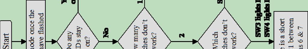
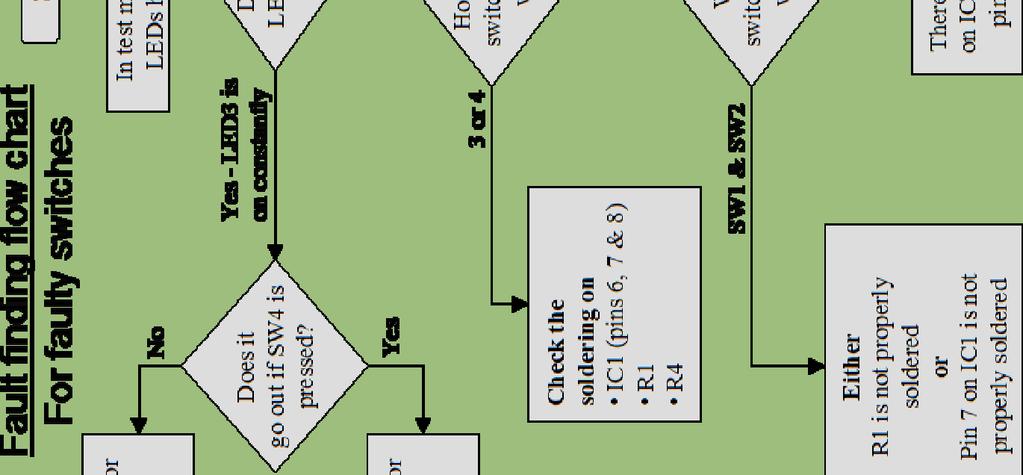
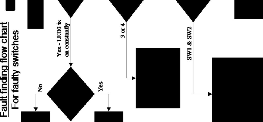
22 Electronic Game Essentials 7 FIT THE IC INTO THE HOLDER The IC can be put into the holder, ensuring that the notch on the chip lines up with the notch on the holder. 8 SECURING THE BATTERY HOLDER Check that the board works before folding the battery holder under the board and fixing in place with the M3 nut and bolt. Checking Your Game PCB Check the following before you insert the batteries: Check the bottom of the board to ensure that: All holes (except the 5 large 3 mm holes) are filled with the lead of a component. All these leads are soldered. Pins next to each other are not soldered together. Check the top of the board to ensure that: The notch on the IC holder / IC is near the edge of the board. The flat edge of each of the LEDs is next to the switch. The colour bands on R7 are yellow, purple, black. Testing the PCB The software on the microcontroller has been specially designed to allow easy testing of the PCB. When the batteries are inserted and SW5 is in the on position, the game will: Illuminate LED1, LED2, LED3 & LED4 in sequence for one second each. o If the LEDs don t light in order, stop testing and look at the LED fault finding flow chart. Once the LEDs have gone out, pressing any of the four buttons will cause the LED next to it to light. o Check that all four buttons work, if this is not the case look at the switch fault finding flow chart. Turn the game off using SW5. If all four buttons tested OK, next time the game is turned on it will work normally.
23 Electronic Game Essentials Using the Game SW5 can be used to turn the game on and off (as indicated on the PCB). When the game is turned on LED1 & LED4 flash rapidly to indicate that a game should be selected. Press SW1 for the memory game or SW4 for the reactions game (both are marked on the PCB). If you wish to change the game you are playing turn the game off and back on and select the other game. Don't forget to switch it off when youre not playing otherwise you will flatten the batteries. Memory game The LEDs will flash a sequence. Simply copy this sequence. If you get it correct the LEDs will quickly flash in turn before the sequence is shown again with an extra LED on the end. When you do get it wrong the LEDs quickly flash in turn three times then your score is shown. The more LEDs you light the better you have done! Reactions game After a random amount of time one of the four LEDs will be illuminated. Simply press the button next to the LED before the LED goes off. If you have pressed the button fast enough then a short while later a new LED will turn on but you have less time to press the button to stay in the game. When you don't manage to press the LED fast enough the LEDs quickly flash in turn three times then your score is shown. The more LEDs you light, the better you have done!
24 Electronic Game Essentials Fault Finding Fault finding flow chart For faulty LEDs Start Power the board up whilst watching the LEDs R7 (the 47 - colour bands yellow, purple, black) has been put in to R1-R6 The LEDs turned on but only very dimly Did the LEDs light? No LEDs turned on One or more LEDs turned on No - one of the LEDs was missing, but then came on at the same time as another LED No - One / two of the LED did not light Check The batteries are good and in the right way around The game is turned on IC1 is present and the notch is near the board edge IC1 pins 1, 2, 8 (nearest the board edge) are soldered properly R7 is present, and soldered properly SW5 is present, and soldered properly The LED that was missing is soldered in to the board the wrong way round Were the LEDs in sequence (LED1, 2, 3, 4)? Yes LEDs are working move on to switch flow chart How many LEDs didnt work? 2 1 Check For a solder shorts on one of the LEDs that didnt light IC1 pins 3 & 5 are soldered correctly For a solder short on IC1 between pins 1 & 2 or pins 2 & 3 The LED that did not light is not properly soldered


25 Electronic Game Essentials
26 Electronic Game Essentials Designing the Enclosure When you design the enclosure, you will need to consider: The size of the PCB Where the LEDs are mounted and how big they are Where the switches are mounted and their size Note: The PCB is symmetrical and, therefore, its length and the position of the LEDs and switches is the same in the vertical direction as well as the horizontal dimensions shown below. This technical drawing of the game should help you to plan this. All dimensions are in mm. Mounting the PCB to the enclosure The drawing to the left shows how a hex spacer can be used with two bolts to fix the PCB to the enclosure. Your PCB has four mounting holes designed to take M3 bolts.
27 Electronic Game Essentials How the Game Works At the heart of the electronic circuit is a microcontroller. A microcontroller is, in effect, a small computer. The circuit uses a cleaver design to allow four switches and four LEDs to be connected to only five input / outputs. The switches are connected to an analogue to digital converter so that it gets a digital representation of the voltage on the input. A set of three resistors is used to make up a potential divider. As each of the resistors is the same value, an equal amount of voltage is present across each of these resistors. The top two resistors also have a switch across them. When the switch is pressed, the voltage across the resistor will become zero. So depending upon which of the two switches is pressed will depend upon what the voltage is at the point where it is fed into the PIC microcontroller. This allows the microcontroller to work out which button is pressed. The third resistor is used to prevent the batteries being rapidly flattened should both switches be pressed at the same time. The other two switches on the board work in the same way. This may sound overly complicated however it uses less input pins than switches with individual pull up resistors. The LEDs are driven by three outputs. Because the LED only works when current flows through it in one direction, the four LEDs can be turned on by changing the outputs to make one high whilst another is low. More than one LED can be turned on if a little dimmer by taking it in turns to turn the LEDs on hundreds of times a second. The 47 resistor limits the current that can flow through the LEDs. This protects the LED and controls the brightness.
28 Online Information Two sets of information can be downloaded from the product page where the kit can also be reordered from. The Essential Information contains all of the information that you need to get started with the kit and the Teaching Resources contains more information on soldering, components used in the kit, educational schemes of work and so on and also includes the essentials. Download from: This kit is designed and manufactured in the UK by Kitronik Every effort has been made to ensure that these notes are correct, however Kitronik accept no responsibility for issues arising from errors / omissions in the notes. Kitronik Ltd - Any unauthorised copying / duplication of this booklet or part thereof for purposes except for use with Kitronik project kits is not allowed without Kitroniks prior consent.
COLOUR CHANGING USB LAMP KIT
 TEACHING RESOURCES SCHEMES OF WORK DEVELOPING A SPECIFICATION COMPONENT FACTSHEETS HOW TO SOLDER GUIDE SEE AMAZING LIGHTING EFFECTS WITH THIS COLOUR CHANGING USB LAMP KIT Version 2.1 Index of Sheets TEACHING
QUIZ BUZZER KIT TEACHING RESOURCES. Version 2.0 WHO ANSWERED FIRST? FIND OUT WITH THIS
 TEACHING RESOURCES SCHEMES OF WORK DEVELOPING A SPECIFICATION COMPONENT FACTSHEETS HOW TO SOLDER GUIDE WHO ANSWERED FIRST? FIND OUT WITH THIS QUIZ BUZZER KIT Version 2.0 Index of Sheets TEACHING RESOURCES
ELECTRONIC GAME KIT ESSENTIAL INFORMATION. Version 2.0 BUILD YOUR OWN MEMORY & REACTIONS
 ESSENTIAL INFORMATION BUILD INSTRUCTIONS CHECKING YOUR PCB & FAULT-FINDING MECHANICAL DETAILS HOW THE KIT WORKS BUILD YOUR OWN MEMORY & REACTIONS ELECTRONIC GAME KIT Version 2.0 Build Instructions Before
RECORD & PLAYBACK KIT
 TEACHING RESOURCES SCHEMES OF WORK DEVELOPING A SPECIFICATION COMPONENT FACTSHEETS HOW TO SOLDER GUIDE ADD AN AUDIO MESSAGE TO YOUR PRODUCT WITH THIS RECORD & PLAYBACK KIT Version 2.1 Index of Sheets TEACHING
8 PIN PIC PROGRAMMABLE BOARD (DEVELOPMENT BOARD & PROJECT BOARD)
") ESSENTIAL INFORMATION BUILD INSTRUCTIONS CHECKING YOUR PCB & FAULT-FINDING MECHANICAL DETAILS HOW THE KIT WORKS LEARN ABOUT PROGRAMMING WITH THIS 8 PIN PIC PROGRAMMABLE BOARD (DEVELOPMENT BOARD & PROJECT
ESSENTIAL INFORMATION BUILD INSTRUCTIONS CHECKING YOUR PCB & FAULT-FINDING MECHANICAL DETAILS HOW THE KIT WORKS LEARN ABOUT PROGRAMMING WITH THIS 8 PIN PIC PROGRAMMABLE BOARD (DEVELOPMENT BOARD & PROJECT
MONO AMPLIFIER KIT ESSENTIAL INFORMATION. Version 2.2 CREATE YOUR OWN SPEAKER DOCK WITH THIS
 ESSENTIAL INFORMATION BUILD INSTRUCTIONS CHECKING YOUR PCB & FAULT-FINDING MECHANICAL DETAILS HOW THE KIT WORKS CREATE YOUR OWN SPEAKER DOCK WITH THIS MONO AMPLIFIER KIT Version 2.2 Build Instructions
7 SEGMENT LED DISPLAY KIT
 ESSENTIAL INFORMATION BUILD INSTRUCTIONS CHECKING YOUR PCB & FAULT-FINDING MECHANICAL DETAILS HOW THE KIT WORKS CREATE YOUR OWN SCORE BOARD WITH THIS 7 SEGMENT LED DISPLAY KIT Version 2.0 Which pages of
ADD AN AUDIO MESSAGE TO YOUR PRODUCT WITH THIS RECORD & PLAYBACK KIT
 ADD AN AUDIO MESSAGE TO YOUR PRODUCT WITH THIS RECORD & PLAYBACK KIT BUILD INSTRUCTIONS Before you start take a look at the Printed Circuit Board (PCB). The components go in the side with the writing on
TECHNOLOGY WILL SAVE US: THE LUMIPHONE
 TECHNOLOGY WILL SAVE US: THE LUMIPHONE This is a step-by-step guide to soldering your own Lumiphone. The equipment you should have at your station: goggles, soldering mat, soldering Iron, solder and side
Introduction 1. Green status LED, controlled by output signal ST. Sounder, controlled by output signal Q6. Push switch on input D6
 Introduction 1 Welcome to the GENIE microcontroller system! The activity kit allows you to experiment with a wide variety of inputs and outputs... so why not try reading sensors, controlling lights or
Introduction 1. Digital inputs D6 and D7. Battery connects here (red wire to +V, black wire to 0V )
") Introduction 1 Welcome to the magical world of GENIE! The project board is ideal when you want to add intelligence to other design or electronics projects. Simply wire up your inputs and outputs and away
Introduction 1 Welcome to the magical world of GENIE! The project board is ideal when you want to add intelligence to other design or electronics projects. Simply wire up your inputs and outputs and away
Introduction 1. Green status LED, controlled by output signal ST
 Introduction 1 Welcome to the magical world of GENIE! The project board is ideal when you want to add intelligence to other design or electronics projects. Simply wire up your inputs and outputs and away
Lab 7: Soldering - Traffic Light Controller ReadMeFirst
 Lab 7: Soldering - Traffic Light Controller ReadMeFirst Lab Summary The two-way traffic light controller provides you with a quick project to learn basic soldering skills. Grading for the project has been
Lab 7: Soldering - Traffic Light Controller ReadMeFirst
 Lab 7: Soldering - Traffic Light Controller ReadMeFirst Lab Summary The two way traffic light controller provides you with a quick project to learn basic soldering skills. Grading for the project has been
MAKE AN RGB CONTROL KNOB.
 MAKE AN RGB CONTROL KNOB. This is a knob based colour changing controller that uses a custom programmed microcontroller to pack a lot of features into a small affordable kit. The module can drive up to
AXE101 PICAXE-08M2 Cyberpet Kit
 AXE101 PICAXE-08M2 Cyberpet Kit The Cyberpet project uses a PICAXE-08M2 microcontroller with two LEDs as the pets eyes and a piezo sounder as a voice for the pet. The project also uses a switch so that
VU-1 VU Meter Kit Volume Unit Meter
 VU-1 VU Meter Kit Volume Unit Meter Simplicity Counts, Detail Matters. No part of this document may be reproduced, either mechanically or electronically, posted online on the Internet, in whole or in part,
Nixie Clock Type Frank 2 Z570M
 Assembly Instructions And User Guide Nixie Clock Type Frank 2 Z570M Software version: 7R PCB Revision: 11 April 09-1 - 1. INTRODUCTION 1.1 About the clock Nixie clock type Frank 2 is a compact design with
Light Emitting Diodes (LEDs)
") Light Emitting Diodes (LEDs) Example: Circuit symbol: Function LEDs emit light when an electric current passes through them. Connecting and soldering LEDs must be connected the correct way round, the diagram
Light Emitting Diodes (LEDs) Example: Circuit symbol: Function LEDs emit light when an electric current passes through them. Connecting and soldering LEDs must be connected the correct way round, the diagram
Total solder points: 123 Difficulty level: beginner 1. advanced AUDIO ANALYZER K8098. audio gea Give your. . high-tech ILLUSTRATED ASSEMBLY MANUAL
 Total solder points: 123 Difficulty level: beginner 1 2 3 4 5 advanced AUDIO ANALYZER K8098 ra audio gea Give your. look high-tech ILLUSTRATED ASSEMBLY MANUAL H8098IP-1 Features & Specifications Features
Mal-2 assembly guide v1.0
 Mal-2 assembly guide v.0 SONIC POTIONS Schematic and BOM The BOM can be found on Google Docs Prepare the PCB Separate the PCBs using some pliers. PCB We start with the lower PCB and assemble it beginning
Obtained from Omarshauntedtrail.com
 http://www.cindybob.com/halloween/ledlighting/ledspotlights/ Introduction In our 2005 haunt providing 120V AC power to the various lights and props requiring it became a fairly large problem. Extension
Tube Cricket Build Guide
 Tube Cricket Build Guide The Tube Cricket is a small-wattage amp that puts out about 1 watt of audio power. With a 12AU7 tube-preamp and a JRC386 power amp, the Tube Cricket gives you great tone in a compact
Nixie Clock Type Frank 3
 Assembly Instructions And User Guide Nixie Clock Type Frank 3 Software version: 7R PCB Version: 11 April 09-1 - 1. INTRODUCTION 1.1 About the clock Nixie clock type Frank 3 is a compact design with all
Assembly Instructions And User Guide. Nixie FunKlock. FunKlock Issue 4 (1 February 2017)
") Assembly Instructions And User Guide Nixie FunKlock - 1 - Issue Number Date REVISION HISTORY 4 1 February 2017 New diode for D2 3 27 December 2013 C7 / C8 error page 15 2 7 November 2013 Errors corrected
Assembly Instructions And User Guide Nixie FunKlock - 1 - Issue Number Date REVISION HISTORY 4 1 February 2017 New diode for D2 3 27 December 2013 C7 / C8 error page 15 2 7 November 2013 Errors corrected
TKEY-K16. Touch CW automatic electronic keyer. (No moving parts no contacts) Assembly manual. Last review: March 15, 2018
 Assembly manual. Last review: March 15, 2018") TKEY-K16 Touch CW automatic electronic keyer (No moving parts no contacts) Assembly manual Last review: March 15, 2018 Commands and use manual of the K16 and Updates and news: www.ea3gcy.com Thanks for
TKEY-K16 Touch CW automatic electronic keyer (No moving parts no contacts) Assembly manual Last review: March 15, 2018 Commands and use manual of the K16 and Updates and news: www.ea3gcy.com Thanks for
SN-Class Nixie Clock Kits
 Assembly Instructions And User Guide SN-Class Nixie Clock Kits - 1 - REVISION HISTORY Issue Date Reason for Issue Number 1 20 November 2017 New document - 2 - 1. INTRODUCTION 1.1 About the How can the
The NorCal SMT Dummy Load Assembly and Operating Manual Rev. 1.0 January 4, 2005
 The NorCal SMT Dummy Load Assembly and Operating Manual Rev. 1.0 January 4, 2005 Copyright 2005 W3CD 1 1. Introduction The NorCal SMT Dummy Load is a practice kit for anyone wishing to gain some experience
SceneStyle2 User Guide
 SceneStyle2 User Guide Mode Lighting (UK) Limited. The Maltings, 63 High Street, Ware, Hertfordshire, SG12 9AD, UNITED KINGDOM. Telephone: +44 (0) 1920 462121 Facsimile: +44 (0) 1920 466881 e-mail: website:
Nixie Clock Kit IN-12B color LED backlit Operation Manual Nixie Clock Kit IN-12B V6.0 ( All Right Reserved 2015 )
") Nixie Clock Kit IN-B color LED backlit Operation Manual Nixie Clock Kit IN-B V. ( All Right Reserved ) - - Operation Manual IN-B Nixie Clock Power for your Nixie Clock The clock does not include a wall
Nixie Clock Kit IN-B color LED backlit Operation Manual Nixie Clock Kit IN-B V. ( All Right Reserved ) - - Operation Manual IN-B Nixie Clock Power for your Nixie Clock The clock does not include a wall
Lab Using The Multimeter And The Trainer
 Lab 2 Sierra College CIE-01 Jim Weir 530.272.2203 jweir43@gmail.com www.rstengineering.com/sierra 1. Using The Multimeter And The Trainer a. Plug the trainer power cord into a standard wall outlet (110
Parts Checklist - Please note there is no resistor R3. Diodes, LED and transistors are polarized see construction stages
 Xtal Check Kit build Read me first! -------- UPDATED GUIDE------ September 12, 2018--------- The following steps are designed to get your Xtal check kit built and operational. This is a good beginner s
Nixie Tube Clock Type Marsden
 Assembly Instructions And User Guide Nixie Tube Clock Type Marsden Software version: RTC-1.3 PCB Revision: 16 Aug 10-1 - 1. INTRODUCTION 1.1 About the clock Nixie clock type Marsden is a compact design
DIY KIT MHZ 8-DIGIT FREQUENCY METER
 This kit is a stand-alone frequency meter capable of measuring repetitive signals up to a frequency of 50MHz. It has two frequency ranges (15 and 50 MHz) as well as two sampling rates (0.1 and 1 second).
Christmas LED Snowflake Project
 Christmas LED Snowflake Project Version 1.1 (01/12/2008) The snowflake is a follow-on from my Christmas star project from a few years ago. This year I decided to make a display using only white LEDs, shaped
Bill of Materials: Super Simple Water Level Control PART NO
 Super Simple Water Level Control PART NO. 2169109 Design a simple water controller in which electrodes are required to sense high and low water levels in a tank. Whenever the water level falls below the
Nixie Clock Type Quattro'
 Assembly Instructions And User Guide Nixie Clock Type Quattro' - 1 - Issue Number Date REVISION HISTORY 2 8 Sept 2012 Errors corrected 1 27 July 2012 New document Reason for Issue - 2 - 1.1 Nixie Quattro
DSO138mini Troubleshooting Guide
 DSO138mini Troubleshooting Guide Applicable main board: 109-13800-00I Applicable analog board: 109-13801-00H 1. Frequently Found Problems 1) LCD completely dark. No backlight 2) LCD lights up but no display
Lesson Sequence: S4A (Scratch for Arduino)
") Lesson Sequence: S4A (Scratch for Arduino) Rationale: STE(A)M education (STEM with the added Arts element) brings together strands of curriculum with a logical integration. The inclusion of CODING in STE(A)M
Lesson Sequence: S4A (Scratch for Arduino) Rationale: STE(A)M education (STEM with the added Arts element) brings together strands of curriculum with a logical integration. The inclusion of CODING in STE(A)M
Documentation VFD clock 8 a clock
 Documentation VFD clock 8 a clock This documentation is protected by our copyright. It must not be used for commercial purposes. Congratulations on your purchase of your VFD clock. To guarantee success
Multi-Key v2.4 Multi-Function Amplifier Keying Interface
 Multi-Key v2.4 Multi-Function Amplifier Keying Interface ASSEMBLY & OPERATION INSTRUCTIONS INTRODUCTION The Harbach Electronics, LLC Multi-Key is a multi-function external device designed for the safe
Bill of Materials: Magic Color PART NO
 Magic Color PART NO. 2193838 Magic color is a guessing game. With this game you can surprise your friends and leave them with amazement, how the game guesses what they have in their minds. Only two selections
DEM 9ULNACK 3.4 GHz. PHEMT LNA amplifier complete kit assembly guide
 DEM 9ULNACK 3.4 GHz. PHEMT LNA amplifier complete kit assembly guide SPECIFICATIONS Noise Figure: < 0.8 db Gain: > 15 db Frequency Range: 3400-3500 MHz Input Voltage: 7-16 VDC Description: The 9ULNACK
Azatrax Model Railroad Track Signal Control - Single Track
 Installation Guide Azatrax Model Railroad Track Signal Control - Single Track TS2 What it is: The TS2 operates one or two trackside block signals (one in each direction) on one track to simulate the block
MAIN PCB (The small one) OPEN MAIN BOARD BAG A
 OPEN MAIN BOARD BAG A") THANKS FOR CHOOSING ONE OF OUR KITS! This manual has been written taking into account the common issues that we often find people experience in our workshops. The order in which the components are placed
THANKS FOR CHOOSING ONE OF OUR KITS! This manual has been written taking into account the common issues that we often find people experience in our workshops. The order in which the components are placed
Australian Technical Production Services
 Australian Technical Production Services Dual Rail Crowbar Copyright notice. These notes, the design, schematics and diagrams are Copyright Richard Freeman, 2015 While I am happy for the notes to be printed
While the parts are already inventoried at the factory, please verify the inventory check as you go:
 Thank you for purchasing the kit for building the WJ9J DTMF controller. After building, you should read the document on operation (WJ9JDTMFControllerV5.pdf) in order to use. This is also in the link in
apple Service Source Apple Studio Display 17" LCD (ADC) Updated 6 Decenber Apple Computer, Inc. All rights reserved.
 Updated 6 Decenber Apple Computer, Inc. All rights reserved.") apple Service Source Apple Studio Display 17" LCD (ADC) Updated 6 Decenber 2004 2003 Apple Computer, Inc. All rights reserved. apple Service Source Take Apart Apple Studio Display 17" LCD (ADC) 2003 Apple
apple Service Source Apple Studio Display 17" LCD (ADC) Updated 6 Decenber 2004 2003 Apple Computer, Inc. All rights reserved. apple Service Source Take Apart Apple Studio Display 17" LCD (ADC) 2003 Apple
N3ZI Digital Dial Manual For kit with Serial LCD Rev 3.04 Aug 2012
 N3ZI Digital Dial Manual For kit with Serial LCD Rev 3.04 Aug 2012 Kit properly assembled and configured for Standard Serial LCD (LCD Not yet connected) Kit Components Item Qty Designator Part Color/Marking
Analog Style LED Clock
 Analog Style LED Clock Operation and Assembly Manual For use with PCB Rev 2.1 Copyright 2018 All Rights Reserved. Manual version 2.1c, for use with PCB revision 2.1, Software version 2.0.0. The electronic
Inputs and outputs. Connecting leads. Buzzer
 Inputs and outputs Mr Bit experiments are designed to help younger pupils get started with connecting sensors and devices to the BBC micro:bit. They are useful 'warm-up' activities before attempting Mr
Pixie Construction Notes
 Pixie Construction Notes PCB V2a February 4 th 2015 Please note that this document is still currently under revision and we apologise for any errors or omissions. Readers should feel free to e-mail any
24 Channel Demultiplexer
 USER GUIDE 24 Channel Demultiplexer Doc. No. : 88 601 27 (408481 A?0/3) k!rand Lighting Issue: 2 Date : Oct 1990 i; Contents INTRODUCTION................................ 1 Delivery Inspection..............................
Fixed Audio Output for the K2 Don Wilhelm (W3FPR) & Tom Hammond (NØSS) v August 2009
 & Tom Hammond (NØSS) v August 2009") Fixed Audio Output for the K2 Don Wilhelm (W3FPR) & Tom Hammond (NØSS) v. 2.1 06 August 2009 I have had several requests to provide a fixed audio output from the K2. After looking at the circuits that
Fixed Audio Output for the K2 Don Wilhelm (W3FPR) & Tom Hammond (NØSS) v. 2.1 06 August 2009 I have had several requests to provide a fixed audio output from the K2. After looking at the circuits that
N3ZI Digital Dial Manual For kit with Backlit LCD Rev 4.00 Jan 2013 PCB
 N3ZI Digital Dial Manual For kit with Backlit LCD Rev 4.00 Jan 2013 PCB Kit Components Item Qty Designator Part Color/Marking PCB 1 LCD Display 1 LCD 1602 Volt Regulator 1 U1 78L05, Black TO-92 Prescaler
Sign Illuminating Ballasts
 Sign Illuminating Ballasts A Complete Range Of Solutions From The Name You Trust Universal Lighting Technologies ( Universal ) is known throughout the sign business as a company that can set and meet today
POINTS POSITION INDICATOR PPI4
 POINTS POSITION INDICATOR PPI4 Monitors the brief positive operating voltage across points motors when they are switched Lights a corresponding led on a control panel to show the last operation of each
Total solder points: 117 Difficulty level: beginner advanced. RGB Controller K8088 ILLUSTRATED ASSEMBLY MANUAL
 Total solder points: 117 Difficulty level: beginner 1 2 3 4 5 advanced RGB Controller K8088 Control incandescent bulbs, LEDs, common anode led strips, etc... ILLUSTRATED ASSEMBLY MANUAL H8088IP-1 Features
Module 4: Traffic Signal Design Lesson 1: Traffic Signal (Arduino) Control System Laboratory Exercise Grade 6-8
 Control System Laboratory Exercise Grade 6-8") Name: Class: Module 4: Traffic Signal Design Lesson 1: Traffic Signal (Arduino) Control System Laboratory Exercise Grade 6-8 Background Traffic signals are used to control traffic that flows in opposing
Name: Class: Module 4: Traffic Signal Design Lesson 1: Traffic Signal (Arduino) Control System Laboratory Exercise Grade 6-8 Background Traffic signals are used to control traffic that flows in opposing
Monday 28 January 2013 Morning
 Monday 28 January 2013 Morning GCSE DESIGN AND TECHNOLOGY Electronics and Control Systems A514/01 Technical Aspects of Designing and Making: Electronics *A528620113* Candidates answer on the Question Paper.
apple Service Source Apple Cinema HD Display 23" LCD (ADC) 11 April Apple Computer, Inc. All rights reserved.
 11 April Apple Computer, Inc. All rights reserved.") apple Service Source Apple Cinema HD Display 23" LCD (ADC) 11 April 2003 2003 Apple Computer, Inc. All rights reserved. apple Service Source Take Apart Apple Cinema HD Display 23" LCD (ADC) 2003 Apple
apple Service Source Apple Cinema HD Display 23" LCD (ADC) 11 April 2003 2003 Apple Computer, Inc. All rights reserved. apple Service Source Take Apart Apple Cinema HD Display 23" LCD (ADC) 2003 Apple
Reaction Game Kit MitchElectronics 2019
 Reaction Game Kit MitchElectronics 2019 www.mitchelectronics.co.uk CONTENTS Schematic 3 How It Works 4 Materials 6 Construction 8 Important Information 9 Page 2 SCHEMATIC Page 3 SCHEMATIC EXPLANATION The
Tip: Faller Mittelstadt Apartments with Controlled LED Lighting Date: , Addition
 Hi All, I have had the 130926 Mittelstadt apartments shown below on my layout for a long time and thought it was about time to add LED lighting to the buildings. With my success at upgrading the Faller
Q1. Do LED lights burn out?
 Here are answers to your LED lighting Frequently Asked Questions. We hope this page is helpful and informative. Be sure to come back from time to time as we continually add to this page to reflect the
Build Your Own Clone Super 8 Kit Instructions
 Build Your Own Clone Super 8 Kit Instructions Warranty: BYOC, Inc. guarantees that your kit will be complete and that all parts and components will arrive as described, functioning and free of defect.
Light Emitting Diodes
 By Kenneth A. Kuhn Jan. 10, 2001, rev. Feb. 3, 2008 Introduction This brief introduction and discussion of light emitting diode characteristics is adapted from a variety of manufacturer data sheets and
Color Organ Triple Deluxe II.
 http://wwwinstructablescom/id/color-organ-triple-deluxe-ii/ Food Living Outside Play Technology Workshop Color Organ Triple Deluxe II by ledartist on January 13, 2013 Table of Contents Color Organ Triple
CR Signals Price List (N Gauge & General) April 2010
 April 2010") Welcome to CR Signals mail order price list price list and order form. Established in 2004, all of our products have been developed over the years and are hand built using the finest materials and latest
Welcome to CR Signals mail order price list price list and order form. Established in 2004, all of our products have been developed over the years and are hand built using the finest materials and latest
MOD028 GLOCKENSPIEL TECHNO-MUSIC-OLOGY
 MOD028 GLOCKENSPIEL TECHNO-MUSIC-OLOGY MOD028 - Techno-music-ology Kit Contents Motor Controller PCBs 14 220R (red red brown gold) resistors 2 330R (orange orange brown gold) resistors 16 1N4001 diodes
Main PCB (The small one)
") Thanks for choosing our kits! This manual is written taking with the problems that we usually find in our workshops in mind. Also the order is meant to make assembly as easy as possible. Some steps are
Thanks for choosing our kits! This manual is written taking with the problems that we usually find in our workshops in mind. Also the order is meant to make assembly as easy as possible. Some steps are
Galilean Moons. dual amplitude transmutator. DIY ASSEMBLY MANUAL v1.02
 Galilean Moons dual amplitude transmutator DIY ASSEMBLY MANUAL v1.02 Contents Contents... 2 Introduction... 3 Eurorack Kit Assembly... 4 Resistors... 4 IC Sockets... 5 Ceramic/Film Capacitors... 5 Transistors
Cambridge International Examinations Cambridge International General Certificate of Secondary Education
 Cambridge International Examinations Cambridge International General Certificate of Secondary Education *7189222356* DESIGN AND TECHNOLOGY 0445/41 Paper 4 Systems and Control October/November 2016 1 hour
XTAL Bank DDS Version 0.02 Sept Preliminary, highly likely to contain numerous errors
 XTAL Bank DDS Version 002 Sept 7 2012 Preliminary, highly likely to contain numerous errors The photo above shows the fully assembled Xtal Bank DDS with 2 DDS modules installed (The kit is normally only
DDS VFO CONSTRUCTION MANUAL. DDS VFO Construction Manual Issue 1.1 Page 1
 DDS VFO CONSTRUCTION MANUAL DDS VFO Construction Manual Issue 1.1 Page 1 Important Please read before starting assembly STATIC PRECAUTION The DDS VFO kit contains the following components which can be
INDICATOR LAMPS & LED REPLACEMENT LAMPS
 INDICATOR LAMPS & LED REPLACEMENT LAMPS Neon indicators (internal resistor) 120VAC 55-452-0 Red lens 120VAC 55-453-0 Amber lens 120VAC 55-455-0 Green lens 120VAC Neon indicators (internal resistor) 120VAC
Ios english manual:ios english manual.qxd 07/08/ :35 Page 1
 Ios english manual:ios english manual.qxd 07/08/2008 10:35 Page 1 Ios english manual:ios english manual.qxd 07/08/2008 10:35 Page 2 Contents Introduction...1 Design Innovation...2-3 Installation...3 Ventilation...4
Fully ly Automaticti. Motorised Satellite t TV System. User s manual REV
 REV. 1.0 Fully ly Automaticti Motorised Satellite t TV System User s manual Customer Help Line: 1300 139 255 Support Email: support@satkingpromax.com.au Website: www.satkingpromax.com.au www.satkingpromax.com.au
SquareLED - Aura Bar & Matrix Beam Light 100
 SquareLED - Aura Bar & Matrix Beam Light 100 1. SAFETY INSTRUCTIONS Please read these instructions carefully they include the important information about the installation usage and maintenance of this
Build your own: Track Display
 Build your own: Track Display! " #! $% $ & ' $ ' ( ) * +, Track Display Manual 0706 web distribution version Table of Contents Section 1 Page 2 Quick Start Guide -Connecting 2 LEDs to Output #1 -Operating
ASSEMBLING. the. ECEbot. Printed Circuit Board: Part Three. Due Date. The Part Three assembly steps must be completed prior to:
 ASSEMBLING the ECEbot Printed Circuit Board: Part Three Due Date The Part Three assembly steps must be completed prior to: Prepared by R.C. Maher September 2008 Copyright 2008 Department of Electrical
Contents. 1. General Information. 2. Contents. 3. Operating Instruction. 4. Program update. 5. Trouble Shooting. 6. Specifications
 Contents 1. General Information 1-1. Introduction 1-2. Proper use and operation 1-3. Safety Notes 2. Contents 2-1. Accessory Include 2-2. Name of parts 3. Operating Instruction 3-1. Connection Diagram
Installing The PK-AM keyer and. from Jackson Harbor Press Operating: A Morse code keyer chip with pot speed control
 Installing The PK-AM keyer and from Jackson Harbor Press Operating: A Morse code keyer chip with pot speed control The PK-AM keyer is a modification for the PK-AM kit, it changes the AM transmitter to
Friday 23 May 2014 Afternoon
 Friday 23 May 2014 Afternoon GCSE DESIGN AND TECHNOLOGY Electronics and Control Systems A515/01 Sustainability and technical aspects of designing and making Electronics *3097109964* Candidates answer on
USER MANUEL. SNIPE 2 Ref R13
 USER MANUEL SNIPE 2 Ref. 0141317R13 Contents 1. General Information 1-1. Introduction 1-2. Proper use and operation 1-3. Safety notes......... 2 3 3 2. Contents 2-1. Accessory included 2-2. Name of parts......
Aspect 2 Circuit Digital Scene Control
 Aspect 2 Circuit Digital Scene Control S p e c i f i c a t i o n 2 circuits of trailing edge dimming 500W total between the two circuits Both circuits feature independent overload, short-circuit and open-circuit
Nixie Clock Type Frank 3'
 Assembly Instructions And User Guide Nixie Clock Type Frank 3' - 1 - REVISION HISTORY Issue Number Date Reason for Issue 4 16 December 2016 New diode for D2 3 12 November 2012 Improved first clock test
SEP Bright Pi v1.0 Assembly Instructions
 SEP Bright Pi v1.0 Assembly Instructions When you purchased your Bright Pi v1.0 kit, you should have received an anti-static bag with some components in it which will require soldering together in order
Integrated Circuit for Musical Instrument Tuners
 Document History Release Date Purpose 8 March 2006 Initial prototype 27 April 2006 Add information on clip indication, MIDI enable, 20MHz operation, crystal oscillator and anti-alias filter. 8 May 2006
E-TEXTILES STARTER PACK
 LEARN HOW TO SEW A CIRCUIT WITH THIS E-TEXTILES STARTER PACK WHITE LEDs BLUE LEDs LARGE COIN CELL MINIATURE COIN CELL SEWABLE ELECTRONICS INTRODUCTION TO ELECTRO-FASHION Electro-Fashion is Kitronik's own
WP36BHD T-1 (3mm) Blinking LED Lamp
 Blinking LED Lamp") T-1 (3mm) Blinking LED Lamp DESCRIPTIONS The Bright Red source color devices are made with Gallium Phosphide Red Light Emitting Diode Electrostatic discharge and power surge could damage the LEDs It is
T-1 (3mm) Blinking LED Lamp DESCRIPTIONS The Bright Red source color devices are made with Gallium Phosphide Red Light Emitting Diode Electrostatic discharge and power surge could damage the LEDs It is
Force & Motion 4-5: ArithMachines
 Force & Motion 4-5: ArithMachines Physical Science Comes Alive: Exploring Things that Go G. Benenson & J. Neujahr City Technology CCNY 212 650 8389 Overview Introduction In ArithMachines students develop
Kingbright. L-7104YD-12V T-1 (3mm) Solid State Lamp DESCRIPTIONS PACKAGE DIMENSIONS FEATURES APPLICATIONS ATTENTION SELECTION GUIDE
 Solid State Lamp DESCRIPTIONS PACKAGE DIMENSIONS FEATURES APPLICATIONS ATTENTION SELECTION GUIDE") T-1 (3mm) Solid State Lamp DESCRIPTIONS The Yellow source color devices are made with Gallium Arsenide Phosphide on Gallium Phosphide Yellow Light Emitting Diode Electrostatic discharge and power surge
T-1 (3mm) Solid State Lamp DESCRIPTIONS The Yellow source color devices are made with Gallium Arsenide Phosphide on Gallium Phosphide Yellow Light Emitting Diode Electrostatic discharge and power surge
16 Stage Bi-Directional LED Sequencer
 16 Stage Bi-Directional LED Sequencer The bi-directional sequencer uses a 4 bit binary up/down counter (CD4516) and two "1 of 8 line decoders" (74HC138 or 74HCT138) to generate the popular "Night Rider"
"Sophisticated Model Railroad Electronics"
 LOGIC RAIL TM "Sophisticated Model Railroad Electronics" TECHNOLOGIES 21175 Tomball Pkwy Phone: (281) 251-5813 Suite 287 email: info@logicrailtech.com Houston, TX 77070 http://www.logicrailtech.com Block
LEDs. Types and Uses. By Wil Davis June 18, 2016
 LEDs (Light Emitting Diodes) Types and Uses By Wil Davis June 18, 2016 Definition Commonly called LEDs. Found every where Basically, LEDs are like tiny light bulbs that fit easily into an electrical circuit.
ENGR 40M Project 3a: Building an LED Cube
 ENGR 40M Project 3a: Building an LED Cube Lab due before your section, October 31 November 3 1 Introduction In this lab, you ll build a cube of light-emitting diodes (LEDs). The cube is wired to an Arduino,
LAMPS & INDICATOR LAMPS
 LAMPS & INDICATOR LAMPS 10.5 M16 x 1.0 55-056-0 Bulk 12V140mA lead wire lamp 55-056-2 Display Package (2) 19.5 14.0 12.0 20.4 7.5 50.4 55-120-0 Bulk NE-2 Neon bulb 55-120-2 Display Package (2) T 3-14 (10mm)
Nixie Clock Type SixNix
 Assembly Instructions And User Guide Nixie Clock Type SixNix - 1 - Issue Number Date REVISION HISTORY Reason for Issue 6 20 March 2014 Removed WWVB Support 5 14 July 2012 New Board Issue - 19 July 12 4
Technology Control Technology
 L e a v i n g C e r t i f i c a t e Technology Control Technology P I C A X E 1 8 X Prog. 1.SOUND Output Prog. 3 OUTPUT & WAIT Prog. 6 LOOP Prog. 7...Seven Segment Display Prog. 8...Single Traffic Light
Atlas Drop In Decoder
 TCS DCC decoders provide the ultimate in control. This decoder is in # A1 Atlas Drop In Decoder 1.3 amp continuous, 2.0 amp peak motor drive plus four 100 ma function outputs Dither creates the ultimate