Service Manual for D9100 Series Digital-Control Color Monitor
|
|
|
- Darlene Tucker
- 5 years ago
- Views:
Transcription
1 Service Manual for D9100 Series Digital-Control Color Monitor Wells-Gardner Electronics 9500 W. 55 th Street Suite A McCook, Illinois (708) X Revision: B / E01025 Date: Printed on 09/30/05
2 INDEX 1. SAFETY PRECAUTION 1 2. SPECIFICATION 2 3. TECHNCIAL FEATURES TIMING CHART SET UP CONTROLS AND ADJUSTMENT ADJUSTMENT SPECIFICATION DESCRIPTION OF CIRCUIT OPERATION TROUBLE SHOOTING.. 22 ii
3 1. SAFETY PRECAUTION: WARNING: Service should not be attempted by anyone unfamiliar with the necessary precautions on this unit. The following precautions are necessary during servicing. 1-1 Some parts, such as a picture tube in this unit, have special safety-related characteristics for X-RAY RADIATION protection. For continued safety, the parts replacement should be undertaken referring to below article (1-2 and 1-5). 1-2 Many electrical mechanical parts in this unit have special safety-related characteristics for protection against shock hazard and others. These characteristics are often passed unnoticed by visual inspection and the protection afforded by them cannot necessarily be obtained by using replacement components rated for higher voltage, wattage, etc. Replacement parts which have these special characteristics are identified in the manual and supplements by shading on the schematic diagram and the parts list. Before replacing any of these components, read the parts list in this manual carefully. 1-3 When replacing the chassis in the cabinet, always be certain that all the protective devices are installed properly, such as insulating covers, strain relief, etc. 1-4 Before replacing the back cover of the set, thoroughly inspect the inside of the cabinet to see that no stray parts or tools have been left inside. 1-5 Before returning the set to the customer, always perform an AC leakage current check on the exposed metallic parts of the cabinet, such as terminal, screwheads, metal overlays, control shafts, etc. To insure the set is safe to operate without danger of electrical shock, plug the AC line cord directly into a 120V AC outlet (do not use a line isolation transformer during this check). Use an AC voltmeter having 5000 ohms per volt or more sensitivity in the following manner. Connect a 1500 ohm, 10 watt resistor, parallel with a (0.15uF) capacitor. Reverse the AC plug in the AC outlet and repeat the AC voltage measurements for each exposed metallic part. Voltage measured must not exceed 0.3V RMS. This corresponds to 0.2mA AC, any value exceeding this limit constitutes a potential shock hazard and must be corrected immediately. 1
4 2. SPECIFICATION: Wells-Gardner Electronics Corporation 2-1 Picture Tube. Size: 14, (18V) Dot Pitch: 14 : mm 15 : mm 17 : mm 19 (18V) : 0.25mm 2-2 Signal Input. Video Input: Analog, Positive Signal (0.7V p-p) Horizontal Sync: TTL Level, Positive or Negative Pulse Scanning : 28 KHz-70KHz Vertical Input: TTL Level, Positive or Negative pulse Scanning : Hz 2-3 Power Supply. Power Input : VAC, 50/60Hz Fuse Rating: 250V, 3.15A Power Consumption 14inch : less than 70W 15inch : less than 80W 17inch : less than 95W 19inch(18V) : less than 110W 2-4 OSD (On Screen Display) Control: Refer to page Operating Temperature: 0 C - 55 C 2-6 Operating Humidity: 10% - 90% (Noncondensing) 2-7 Net Weight 14inch : 22 lbs. (10kg) 15inch : 24 lbs. (11kg) 17inch : 33 lbs. (15kg) 19inch(18V) : 37 lbs. (17kg) 2
5 3. TECHNICAL FEATURES: 3.-1 Microprocessor control with OSD (On screen display menu). Microprocessor recognizes the input computer signal and signal output from the customer control board connected to the main board by a flat cable. 3-2 Universal AC Input Voltage. Power supply operates on VAC at 60/50Hz for use all over the world Protection Circuit for over-current. When an over-current condition occurs in the circuit, the protection circuit operates in order to prevent the components from electrical shock or other risks. 3-4 Override function. A (NO SIGNAL MESSAGE) is displayed on the screen if no signal is present at the signal input cable while the monitor is powered on. 3-5 Control panel. If you require different display characteristics other than the factory mode presets of size, position, color settings, use the control panel to program it to your requirements in each resolution mode. These adjusted settings are kept in memory even if you change resolution mode or turn off the monitor. 3-6 I²C BUS control. The monitor is designed with I²C BUS control for simplifying the circuitry. The number of total components is less than 610 pcs. 3
6 4. TIMING CHART: Wells-Gardner Electronics Corporation Factory Pre-Set Timing Modes. Horizontal and Vertical Timing Diagram for Table 1. TABLE 1 : DESCRIPTION MODE 1 MODE 2 MODE 3 MODE 4 VGA 720*400 VGA 640* /A 1024*768 S-VGA 680*480 FH KHz KHz KHz KHz A µs µs µs µs B 3.813µs 3.813µs 3.920µs 2.032µs H C 1.907µs 1.589µs 1.247µs 3.810µs D µs µs µs µs E 0.636µs 0.318µs 0.170µs 0.508µs POL. NEGATIVE NEGATIVE POSITIVE NEGATIVE FV Hz Hz Hz Hz A ms ms ms ms B 0.064ms 0.064ms 0.113ms 0.080ms V C 1.112ms 0.794ms 0.563ms 0.427ms D ms ms ms ms E 0.381ms 0.064ms 0.014ms 0.027ms POL. POSITIVE NEGATIVE POSITIVE NEGATIVE VIDEO ANALOG ANALOG ANALOG ANALOG 4
7 TABLE 1 (CONTINUED) : DESCRIPTION H V FH A B C D E POL. FV A B C D E POL. VIDEO MODE 5, S-VGA VESA 800* KHz µs 3.200µs 2.200µs µs 1.000µs POSITIVE Hz ms 0.106ms 0.607ms ms 0.026ms POSITIVE ANALOG MODE 6 MODE 7 VGA MODE 8 VGA 800*600 VESA 800*600 VESA 1024* KHz KHz KHz µs µs µs 1.616µs 2.400µs 2.231µs 3.232µs 1.280µs 1.615µs µs µs µs 0.323µs 1.119µs 0.998µs POSITIVE POSITIVE NEGATIVE Hz Hz Hz ms ms ms 0.064ms 0.125ms 0.124ms 0.448ms 0.478ms 0.600ms ms ms ms 0.021ms 0.722ms 0.062ms POSITIVE POSITIVE NEGATIVE ANALOG ANALOG ANALOG DESCRIPTION H V FH A B C D E POL. FV A B C D E POL. VIDEO MODE 9 MODE 10 MODE 11 MODE 12 VESA 800*600 VESA 1024*768 VESA 1024*768 VESA 1280* KHz µs KHz µs KHz µs KHz µs 1.138µs 1.813µs 1.219µs 1.037µs 2.702µs 1.920µs 2.235µs 2.296µs µs µs µs µs 0.569µs 0.321µs 0.203µs 0.360µs POSITIVE NEGATIVE POSITIVE POSITIVE Hz Hz Hz Hz ms ms ms ms 0.056ms 0.106ms 0.050ms 0.047ms 0.503ms 0.513ms 0.466ms 0.594ms ms ms ms ms 0.019ms 0.054ms 0.017ms 0.016ms POSITIVE NEGATIVE POSITIVE POSITIVE ANALOG ANALOG ANALOG ANALOG MODE 13 VESA 1024* KHz µs 1.016µs 2.201µs µs 0.508µs POSITIVE Hz ms 0.044ms 0.524ms ms 0.015ms POSITIVE ANALOG 5
8 5. SET UP: Wells-Gardner Electronics Corporation Setting up your monitor is easy. All you have to do is make a few simple connections and adjustments. The procedure is as follows: 5.1 Start Up. Your monitor starts up automatically when you insert the power plug to power source Single Cable Connection. Connect the 15pin signal cable to the source and lock both screws to ensure that the monitor is properly grounded. D type 15pin connector: PIN NO. DESCRIPTION PIN NO. DESCRIPTION 1 VIDEO RED 9 N.C. 2 VIDEO GREEN 10 GROUND 3 VIDEO BLUE 11 N.C. 4 N.C. 12 SDA 5 N.C. 13 HOR-SYNC 6 VIDEO RED GROUND 14 VER-SYNC 7 VIDEO GREEN GROUND 15 SCL 8 VIDEO BLUE GROUND 6
9 6. CONTROLS AND ADJUSTMENTS: There are four switches on the control panel. Adjustable controls allow the best display status for individual requirements Key Function. MODE/EXIT MODE Call the Main-Menu OSD SEL SEL Call the Sub-Menu OSD DOWN/UP When the Main-Menu is displayed, you can select each function using these keys. When the Sub-Menu is displayed, you can change the amplitude of the selected function of the screen using these keys O.S.D. CONTROL METHOD. User Adjustment. Location Adjustment Method Function CUSTOMER CONTROL PCB MAIN PCB OSD CONTROL VR control, VR501 VR301 FBT *NOTE: (FACTORY ADJUSTED AND EPOXYED) (HOT MELTED SCREEN FBT) Brightness Contrast Horizontal Position Horizontal Size Vertical Position Vertical Size Side Pincushion Trapezoid Pin Balance Parallelogram Sub-Bright H.V. Adjustment* Focus and Screen 7
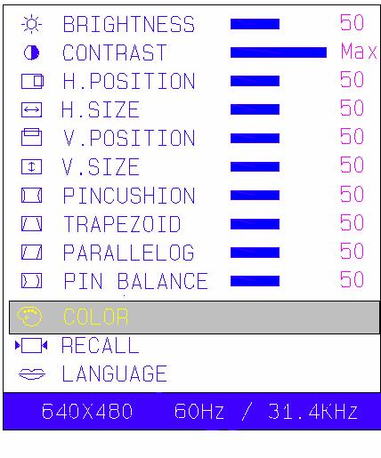
10 6-3. OSD Controls - User s control. Wells-Gardner Electronics Corporation A. BRIGHTNESS ADJUSTMENT. 1) Press the MODE key then Main-Menu OSD comes out as figure on next page. 2) Search BRIGHTNESS sub-menu using UP/DOWN key on the Main- Menu OSD. 3) Select the BRIGHTNESS by pressing SEL key. The BRIGHTNESS OSD color changes from yellow to red. 4) Adjust Brightness as much as you want using UP/DOWN key. 5) After finishing the Brightness adjust, press the MODE key. The BRIGHTNESS OSD color changes from red to yellow and the changed Brightness value saves automatically. 6) If you want to adjust other functions (sub-menu), search the function using UP/DOWN keys, and then repeat the same procedures of steps ) Press the MODE key again to finish adjustments and the OSD will disappear. If no action is taken in the OSD, the menu will disappear by itself. 8


11 A. BRIGHTNESS ADJUSTMENT B. CONTRAST ADJUST SAME ABOVE C. H. POSITION ADJUST SAME ABOVE D. H. SIZE ADJUST SAME ABOVE E. V. POSITION ADJUST SAME ABOVE F. V. SIZE ADJUST SAME ABOVE G. PINCUSHION ADJUST SAME ABOVE H. TRAPEZOID ADJUST SAME ABOVE I. PARRALLELOG ADJUST SAME ABOVE J. PIN BALANCE ADJUST SAME ABOVE 9

12 6-3 OSD Controls (continued): K. COLOR ADJUST 10

13 L. RECALL. When the RECALL key is pressed, all user s adjustment values are changed to the factory values. M. LANGUAGE. The menu is available in four languages. 1. Press the MODE key and the Main-Menu OSD will appear as in the previous figure. 2. Search the LANGUAGE sub-menu using the UP/DOWN key on the Main-Menu OSD. 3. Select the LANGUAGE by pressing the SEL key. Then the Language sub-menu will appear as in the following figure 4. Search any language using the UP/DOWN key. 5. Select a language by pressing the SEL key. 6. Press MODE key to finish and save the selected language. Then the OSD will return to Main-Menu in the selected language. Press the MODE key again to finish the adjustment then the OSD will disappear. 11
14 7. ADJUSTMENT SPECIFICATION: 7-1. Adjustment Sequence: The monitor requires a minimum of 15 minutes of warm up time before adjustment Adjustment Sequence: FBT B+ Voltage G2 Voltage Hor. Center Hor. Size Hor. Position Ver. Size Ver. Position Side-pin Trapezoid Focus White Balance Convergence (if needed) 7-3. Adjustment Procedure. How to enter the Factory Mode: Press Menu and Down simultaneously and hold down for 3 seconds. Adjust BRIGHTNESS and CONTRAST to 50 amplitude FBT B+ voltage adjustment. (For Flyback replacement only) 1. Input the crosshatch pattern with the 31KHz 640*480 mode. 2. After connecting a digital voltmeter to D316, cathode and the frame ground, adjust FBT B+ voltage to 76V +/- 0.5V using VR301. (Pot is glued) G2 Voltage adjustment. 1. Input the crosshatch pattern with 31 KHz 640*480 mode 2. Adjust the G2 for visible background. 3. Adjust G1, VR501, for 35 +/- 1vdc Geometry/Display Adjustment. Refer to controls and adjustment (Article 6) Focus Adjustment 1. Input the H character pattern with 31 KHz 640* Adjust the focus for the best balance at each point of A,B,C,D,E as shown below by rotation the focus VR of FBT 3. For Dual Focus 17 monitors, adjust FOCUS 1 and FOCUS 2 for sharpest horizontal and vertical lines on a crosshatch pattern in oval area from point B to point C of display. Check overall focus in center and corners. 12
15 7-3.5 Purity and Convergence Adjustment. (If Required) A. Purity Adjustment. 1. Demagnetize the picture tube and cabinet using a degaussing coil. 2. Turn the CONTRAST and BRIGHTNESS controls to maximum. 3. In User Color Menu, adjust RED and BLUE controls to provide only a green raster. 4. Loosen the clamp screw holding the yoke and slide the yoke backward to provide vertical green belt (zone) in the picture screen. 5. Remote the Rubber wedges 6. Rotate and spread the tabs of the purity magnet around the neck of the picture tube until the green belt is in the center of the screen. At the same time, center the raster vertically. 7. Move the yoke slowly forward until a uniform green screen is obtained. Tighten the clamp screw of the yoke temporarily. 8. Check the purity of the red and blue raster by adjusting COLOR controls. 9. Obtain a white raster referring to CRT GRAY SCALE ADJUSTMENT 10. Proceed with convergence adjustment. B. Convergence adjustment: 1. Change to a crosshatch pattern with a color signal generator. 2. Adjust the BRIGHTNESS and CONTRAST controls for well defined pattern. 3. Adjust two tabs of the 4-pole magnets to change the angle between them and superimpose red and blue vertical lines in the center of the picture screen. 4. Turn both tabs at the same time keeping their angles constant to superimpose red and blue horizontal lines at the center of the screen. 5. Adjust two tabs of 6-pole magnets to superimpose red/blue line with green one. Adjusting the angle affects the vertical lines and rotating both magnets affects the horizontal line. 6. Repeat adjustments 3,4 and 5, keeping in mind red, green and blue movement, because 4-pole magnets and 6-pole magnets interact and make dot movement complex. 13
16 7-3.6 White Balance adjustment (video). 1. Warm up the unit for 15 minutes 2. Input the window pattern with 31KHz 640*480 mode. 3. Adjust the color temperature to be X=0.289+/ and Y=0.305+/ by R.G.B. gain on User Color Menu or User Preference. 7-4 OSD FACTORY CONTROL This should be adjusted by a technician or qualified repair personnel. This monitor has two-adjustment modes. One is for the user s own adjustment and other is for factory adjustment. But sometimes adjustments in the factory adjustment modes are needed for repair. Caution: More precautions must be made in the factory adjustment mode compared to the user mode, because after finishing adjustments in the factory mode, if wrong values have been entered, you can not revert back to the old settings. At the user mode, if there are mistakes, you can use the RECALL function (refer to 6-3 M item) to go back to the previous settings. In factory mode, the RECALL function will only display your current settings. A. Factory mode entering. Press the MODE and DOWN key simultaneously until the OSD comes out as below. The OSD of factory mode is the same format with user mode except for the color of the bottom line. (User mode is blue; factory mode is red). 14
17 B. Exit and save. (Save is automatic) 1. After finishing adjustments, select RECALL using UP/DOWN key. 2. Press SEL key until OSD disappears. The adjusted value is saved and exits from the factory mode. C. Adjustment. All adjustment methods are same as user s control mode except COLOR 7-5 White balance Adjustment: A. Pre-adjustment. 1. Warm up monitor for 15 minutes. 2. Input the small window pattern with 31KHz 640*480 mode. 3. Degauss the screen with External degaussing coil. White Balance adjustment (background raster). 1. Remove the video signal. 2. Adjust the sub-brightness of background raster to be 1.0FtL +/- 0.3FtL with SUB BRIGHTNESS control VR501. B. COLOR ADJUSTMENT. COLOR K: X=0.289, Y=0.305 COLOR K: X=0.312, Y=0.329 Check at 2.5fL (BIAS), 50fL (GAIN) light output levels. Reference size, Horizontal and Vertical 3/8 from CRT phosphor edges. 1. It is best to use a centered small white box pattern. Before adjusting the COLOR. CONTRAST should be set at the maximum and BRIGHTNESS should be set to In the factory mode, toggle down to COLOR using UP/DOWN key. 3. Select COLOR by pressing SEL key. Color sub-menu appears as left below figure. 4. Search a color temperature you want to adjust (gain or bias) using UP/DOWN ( GAIN is the high-beam area s adjustment and BIAS, the low-beam.) 5. Select any item desired by pressing SEL key then the OSD changes to the sub-menu as shown in figure below-right. 6. Adjust color temperature using SEL and UP/DOWN key. ( SEL key: moves item position, UP/DOWN key: changes value.) 7. In the GAIN mode, CO means sub-contrast adjustment. Subcontrast is adjusted using UP/DOWN key. 8. Press the MODE key to finish the GAIN or BIAS adjustment. 9. If you want to adjust other GAIN or BIAS, repeat from steps Press MODE key again to finish the COLOR adjustment. 11. When done with the factory adjustment, select RECALL as in step B. Exit and save. 15
18 7-5 B. Color Adjustment Wells-Gardner Electronics Corporation 16
19 8. DESCRIPTION OF CIRCUIT OPERATION: 8-1. Mode Control H-Sync is inputted to pin 30 of IC601, V-Sync to pin 29 of IC601 for each mode and pin 27, 26 of IC601 output always positive polarity sync The outputs from IC601 are as below (See table 1) No. Frequency Range of Frequency OUTPUT (MCU PIN) Hf Vf Resolution (CS3) (CS2) (CS1) OFF ST-BY SUS-P LED Hf (KHz) Vf (Hz) KHz Hz x ~ ~ 72 L L L L H L L X480 " 58 ~ 62 L L L L H L L X ~ ~ 88 H L L L H L L X ~ ~ 77 H H L L H L L X ~ ~ 62 H H L L H L L X600 41~ ~ 77 H L H L H L L X600 " 70 ~ 74 H L H L H L L X768 " 58 ~ 62 H L H L H L L X ~ ~ 87 L H H L H L L X768 " 68 ~ 72 L H H L H L L X768 " 73 ~ 77 L H H L H L L x ~ ~ 62 H H H L H L L x ~ ~ 87 H H H L H L L 17
20 8-2 Deflection Processor (IC301): Horizontal section Horizontal Oscillation. Horizontal free frequency is set to 48KHz by R314 and C347. Autosync processing can be done from 28KHz to 70KHz by means of IC301 without any adjustment Phase Shift. Horizontal phase shift is controlled by IC601 using I²C BUS control Horizontal driver output. The output pulse which has the duty-cycle of 47% is available at pin 26 of IC301. The output is used by the horizontal drive circuit B+ control driver output. The output pulse is available at pin 6 of IC301 and it is used for the horizontal scan voltage control driver X-Ray protection. When the flyback voltage rises up to an unacceptable level, X-ray protection is activated. When the X-ray input pin 25 of IC301 is above 8V, the internal latch in IC301 is turned on. This stops all line drive output to the horizontal circuits. To reset the protection circuit, remove main power to the monitor for 5 seconds. 18
21 8-2.2 Vertical section: Vertical oscillation. The free running frequency of the vertical oscillator is determined by the capacitor C342 at pin VCAP (pin22) of IC Vertical amplitude. Vertical amplitude is controlled by IC601 using I²C bus control Vertical position. Vertical position is controlled by IC601 using I²C bus control East-west parabola. A parabola wave-form is available on pin 24 of IC301 for driving the pincushion correction stage. Amplitude of parabola waveform is controlled by IC601 using I²C B+ Regulator. B+ PWM regulator output is available on pin 28 of IC301 for driving the B+ control stage. This PWM output is adjusted through VR Vertical Deflection (IC201): IC201 (KA2142) is used for direct driving of the vertical deflection yoke. 8-4 Horizontal scan voltage control stage: The set-up converter is used in this stage. The output pulse at pin 28 of the IC301 is synchronized on horizontal frequency. This pulse is operated via buffer stage Q311/Q312. This output is rectified through D315/L304. In this way, the supply voltage to the flyback transformer can be proportional to the horizontal line frequency. 19
22 8-5 Horizontal deflection output stage: Line driver stage. As a driver device, small MOSFET Q307(IRF630A) is used. The driver transformer T302 is equipped with a snubber circuit (R327/C309) at the primary side to damp excessive ringing Horizontal power output stage. The horizontal power output stage is a conventional one with a diode modulator. As a deflection transistor, the Q302 (KSC5802/3) is used. To compensate for horizontal linearity, T301 is connected in series with the horizontal DY. It is controlled by DC voltage of Q304 collector, which the base voltage of Q304 is integrated from output at pin 40 of IC S-Correction capacitor switches. Q316 is off when horizontal frequency is 35KHz Q316, Q317 is off when horizontal frequency is 37KHz Q316, Q318 are off when horizontal frequency is 43KHz-52KHz Q317, Q318 is off when horizontal frequency is 53KHz 61KHz Q316, Q317, Q318 is off when horizontal frequency is 62KHz 70KHz Q316, Q318 is off when input is override condition 8-6 FBT (Flyback Transformer): The high voltage for CRT anode focus, G2 voltage for CRT and 12V for vertical deflection are generated by the FBT. Also, -130V for G1 voltage, horizontal flyback pulse, +120V video supply, and for dual focus units 450V dynamic focus supply. 8-7 ABL (Automatic Beam Limiting): The voltage of point 7 depends on the anode current of FBT. So, the voltage at pin 7 of the FBT decreases with increasing anode current. That time, using at this level, increase contrast setting level limited a certain level (300µA in white pattern) that is set by inner voltage of IC
23 8-8 Video amplification section: Video pre-amplifier(ic401). Input video signals are amplified by means of IC401, and the amplified signals drive the video output stage (IC402). Video gain is adjusted by DC voltage at pin 12 for ABL control Video output stage (IC402). The video output signals from IC401 are amplified again by IC402, and IC402 applies video signals to each cathode of the CRT. Cutoff voltages are adjusted by Q405, Q406, and Q407 which is operated by I²C BUS control through the microprocessor OSD (On Screen Display : IC403). The OSD signal is applied from IC403 to IC402. It is controlled by I²C BUS control line. 21
24 9. TROUBLESHOOTING: 9-1. NO POWER. 22
25 9-2. NO VIDEO: 23
26 9-3. NO RASTER: 24
27 9-4 TROUBLE IN HORIZONTAL SIZE: 25
28 9-5. TROUBLE IN CONTRAST: 26
29 9-6. TROUBLE IN BRIGHTNESS: 27
User Manual for D9400 D9410 Series Digital-Control Color Monitor
 User Manual for D9400 D9410 Series Digital-Control Color Monitor Wells-Gardner Electronics 9500 W. 55th Street Suite A Mc Cook, Il. 60525-3605 (708) 290-2100 Revision ORG/E11004 D9400 User manual Date
SERVICE AND OPERATION MANUAL
 MTG-XX02XT/XN Publication A. Issue 1 SERVICE AND OPERATION MANUAL MTG- XX02XT/XN OPEN FRAME XVGA COLOR MONITORS MTG-1702XT/XN : 17INCH, FST MTG-1902XT/XN : 19INCH, FST Information in this publication current
SERVICE AND OPERATION MANUAL
 MTG-2907TN Publication A. Issue 1 SERVICE AND OPERATION MANUAL MTG- 2907TN OPEN FRAME VGA COLOR MONITORS MTG-2907TN : 29INCH, FST Information in this publication current as of Jun, 2003. Information subject
SERVICE AND OPERATION MANUAL
 MTG-XX02SN/SE Publication A. Issue 1 SERVICE AND OPERATION MANUAL MTG- XX02SN/SE OPEN FRAME SVGA COLOR MONITORS MTG-2902SN/SE : 29INCH, FST MTG-3302SN/SE : 33INCH, FST MTG-3802SN/SE : 38INCH, FST Information
HIGH RESOLUTION MONITOR
 HIGH RESOLUTION MONITOR 29" Pure Flat 15K-40Khz Installation Instruction WARNING Primary side and Secondary side The monitor's circuit which is divided into the primary side and secondary side, is insulated.
BLOCK DIAGRAM. Brightness Control -120V. Vertical Blanking, FBT 30V 15V. Protection TDA8172 ( IC601) Circuit -12V 12V. H/V Sync Processor
 Circuit -12V 12V. H/V Sync Processor") BLOCK DIAGRAM H.V DY CDT H- Conver gence Dynamic Focus Static Focus Auto Beam Limit Heater ( ) Screen G1 < OSD > H / V POSITION H / V SIZE SPCC TRAPIZODE PIN BALANCE PARALLELOGRAM CORNERTRAP DDC ON/OFF
BLOCK DIAGRAM H.V DY CDT H- Conver gence Dynamic Focus Static Focus Auto Beam Limit Heater ( ) Screen G1 < OSD > H / V POSITION H / V SIZE SPCC TRAPIZODE PIN BALANCE PARALLELOGRAM CORNERTRAP DDC ON/OFF
4. Alignment and Adjustments
 4. Alignment and Adjustments 4-1 Preadjustment 4-1-1 Factory Mode 1. Do not attempt these adjustments in the Video Mode. 2. The Factory Mode adjustments are necessary when either the EEPROM (IC02) or the
ELECTRICAL ADJUSTMENT INSTRUCTIONS
 ELECTRICAL ADJUSTMENT INSTRUCTIONS General Note: "CBA" is abbreviation for "Circuit Board Assembly." NOTE: Electrical adjustments are required after replacing circuit components and certain mechanical
Brief Description of Circuit Functions. The brief ckt. description of V20 107E5 17 Monitor
 Exhibit 4 Brief Description of Circuit Functions The brief ckt. description of V20 107E5 17 Monitor 0. Functional Block Diagram 1. General Description 2. Description of Circuit Diagram A. Power Supply
FOCUS VOLTAGE ADJUSTMENT 1. Receive RETMA pattern signal. 2. Adjust the FOCUS VOLUME on the FBT and make the picture on the screen be finest.
 General Information Also Covers: DVT-1484D, DVT-2084D Ferguson FG 14 CB 12V, FG 20 CB 12V Goodmans TVC 1400 & TVC 14 VP Electrical Adjustments (TV) GENERAL INFORMATION All adjustments are throughly checked
4. Alignment and Adjustments (Electrical)
") 4. Alignment and Adjustments (Electrical) 4- Preadjustment 4-- Factory Mode. Do not attempt these adjustments in the Video Mode. 2. The Factory Mode adjustments are necessary when either the EEPROM (IC92)
4. Alignment and Adjustments (Electrical) 4- Preadjustment 4-- Factory Mode. Do not attempt these adjustments in the Video Mode. 2. The Factory Mode adjustments are necessary when either the EEPROM (IC92)
4. Alignment and Adjustments
 Alignment and Adjustments 4. Alignment and Adjustments 4-1 Preadjustment 4-1-1 Factory Mode 1. Do not attempt these adjustments in the Video Mode. 2. The Factory Mode adjustments are necessary when either
K Service Source. Apple High-Res Monochrome Monitor
 K Service Source Apple High-Res Monochrome Monitor K Service Source Specifications Apple High-Resolution Monochrome Monitor Specifications Characteristics - 1 Characteristics Picture Tube 12-in. diagonal
SPECIFICATIONS. 1. PICTURE TUBE : 19 inch (Flat Square Tube) DefIection Angle : 90 Neck Diameter : 29.1mm Transmission : 52%
 DefIection Angle : 90 Neck Diameter : 29.1mm Transmission : 52%") SPECIFICATIONS 1. PICTURE TUBE Size : 19 inch (Flat Square Tube) DefIection Angle : 90 Neck Diameter : 29.1mm Transmission : 52% Dot Pitch : 0.26mm Face Treatment : E-Coating 3. POWER SUPPLY 3-1. Power
SPECIFICATIONS 1. PICTURE TUBE Size : 19 inch (Flat Square Tube) DefIection Angle : 90 Neck Diameter : 29.1mm Transmission : 52% Dot Pitch : 0.26mm Face Treatment : E-Coating 3. POWER SUPPLY 3-1. Power
K Service Source. Apple High-Res Monochrome Monitor
 K Service Source Apple High-Res Monochrome Monitor K Service Source Specifications Apple High-Resolution Monochrome Monitor Specifications Characteristics - 1 Characteristics Picture Tube 12-in. diagonal
V25 V25+ WS WS WS WS V27 WS-65517
 2005 Down to1 HIGH SPEED TROUBLESHOOTING V25-V27 CHASSIS V25 V25+ WS-48515 WS-55615 WS-55515 WS-65615 WS-65515 WS-73615 V25++ WS-55815 WS-65815 WS-55517 V27 WS-65517 WS-73517 MITSUBISHI DIGITAL ELECTRONICS
4.9 BEAM BLANKING AND PULSING OPTIONS
 4.9 BEAM BLANKING AND PULSING OPTIONS Beam Blanker BNC DESCRIPTION OF BLANKER CONTROLS Beam Blanker assembly Electron Gun Controls Blanker BNC: An input BNC on one of the 1⅓ CF flanges on the Flange Multiplexer
CONTENTS 1. PRECAUTIONS PRODUCT SPECIFICATION
 COLOR MONITOR KT-2914DF SERVICE MANUAL CONTENTS 1. PRECAUTIONS -------------------------------------------------- 2 2. PRODUCT SPECIFICATION -------------------------------- 5 3. OPERATING INSTRUCTION
CP-830FP Chassis TX-29E50D TX-29E50D/B TX-29PS12D TX-29PS12F TX-29PS12P SPECIFICATIONS. Order No: PCZ C2
 Order No: PCZ0510103C2 SPECIFICATIONS Power Source: Power Consumption: 220-240V a.c.,50hz 100W Stand-by Power Consumption: 1,5W Aerial Impedance: 75Ω unbalanced, Coaxial Type Receiving System: PAL-I, B/G,
GME. User s Manual. Rev 1.3
 GME User s Manual Rev 1.3 TEST INSTRUMENT SAFETY GUIDELINES WARNING An electrical shock of over 10 milliamps of current to pass through the heart will stop most human heartbeats. Voltage as low as 35 volts
Hi-Rez Projections Inc. 20 Main St. Ashland, MA MP8 CRT Installation
 Hi-Rez Projections Inc. 20 Main St. Ashland, MA 01721 508-881-1613 www.hometheater1.com MP8 CRT Installation Table of Contents Overview...1 Precautions...1 Components...1 CAUTIONS Before Beginning...2
K Service Source. Macintosh Color Display
 K Service Source Macintosh Color Display K Service Source Specifications Macintosh Color Display Specifications Characteristics - 1 Characteristics Picture Tube 14-in. diagonal (11.5-in. viewable image)
NewScope-7A Operating Manual
 2016 SIMMCONN Labs, LLC All rights reserved NewScope-7A Operating Manual Preliminary May 13, 2017 NewScope-7A Operating Manual 1 Introduction... 3 1.1 Kit compatibility... 3 2 Initial Inspection... 3 3
GME. User s Manual. Rev 1.3
 GME User s Manual Rev 1.3 TEST INSTRUMENT SAFETY GUIDELINES WARNING An electrical shock of over 10 milliamps of current to pass through the heart will stop most human heartbeats. Voltage as low as 35 volts
PREPARATION FOR SERVICING
 How to Enter the Service Mode PREPARATION FOR SERVICING Caution: 1 1. Optical sensors system are used for Tape Start and End Sensor on this equipment. Read this page carefully and prepare as described
CONTENTS 1. PRECAUTIONS PRODUCT SPECIFICATION
 COLOR MONITOR KT-1982* SERVICE MANUAL CONTENTS 1. PRECAUTIONS -------------------------------------------------- 2 2. PRODUCT SPECIFICATION -------------------------------- 5 3. OPERATING INSTRUCTION --------------------------------
HIGH DEFINITION MONITOR HDM 5049 PLUS USER S MANUAL
 BARCO N.V. Communication Systems Th. Sevenslaan 106 B-8500 Kortrijk (Belgium) Tel.: +32.56.233.211 Fax: + 32.56.233.461 E-mail: support.bcs@barco.com Web site: http://www.barco.com HIGH DEFINITION MONITOR
Service Service Service. B8 Series Chasssis Manual Contents 5. Service Modes, Error Codes and Faultfinding 6. Block Diagrams and Testpoints
 Color Television Service Service Service Chassis B8 Series Chasssis Manual 7562 Contents 5. Service Modes, Error Codes and Faultfinding 6. Block Diagrams and Testpoints 7. Electrical Diagrams and PWB's
12.1 Inch CGA EGA VGA SVGA LCD Panel - ID #492
 12.1 Inch CGA EGA VGA SVGA LCD Panel - ID #492 Operation Manual Introduction This monitor is an open frame LCD Panel monitor. It features the VESA plug & play system which allows the monitor to automatically
TV2K - TXT SERVICE MANUAL COLOUR TELEVISION RECEIVER SECIFICATION
 TV2K - TXT COLOUR TELEVISION RECEIVER SERVICE MANUAL SECIFICATION SYSTEM PAL/SECAM,B/G,I. POWER INPUT AC 170-245V(50/60Hz) POWER CONSUMPTION 60W AERIAL IMPEDANCE 75OHM UNVALANCED TUNER VOLTAGE SYNTHESIZER
Winmate Communication INC.
 20.1 Military Grade Display Model: R20L100-RKA2ML User s Manual Winmate Communication INC. May, 2011 1 IMPORTANT SAFETY INSTRUCTIONS Please read these instructions carefully before using the product and
K Service Source. Macintosh 12 RGB Display
 K Service Source Macintosh 12 RGB Display K Service Source Specifications Macintosh 12" RGB Display Specifications Characteristics - 1 Characteristics Picture Tube 12-in. viewable diagonal screen 90 deflection
OPERATING INSTRUCTIONS FOR SYLVANIA. Type I08 Cathode-Ray Oscilloscope. Sylvania Electric Products Inc. Industrial Apparatus. Emporium, Pennsylvania
 OPERATING INSTRUCTIONS FOR SYLVANIA Type I08 Cathode-Ray Oscilloscope Sylvania Electric Products Inc. Industrial Apparatus Plant Emporium, Pennsylvania OPERATING INSTRUCTIONS FOR Sylvania Type 08 Cathode-Ray
6.4 Chassis Monitor Model Number: LCM0642xx. SPEC No.: SAS Version: 0.0 Issue Date: April 16, Introduction:
 6.4 Chassis Monitor Model Number: LCM0642xx This product is RoHS compliant SPEC No.: SAS-0908003 Version: 0.0 Issue Date: April 16, 2010 1. Introduction: 1.1 About the Product The LCM0642xx 6.4 Chassis
26 Inch CGA/EGA/VGA/DVI to WXGA/1080p LCD - ID#703
 26 Inch CGA/EGA/VGA/DVI to WXGA/1080p LCD - ID#703 Operation Manual Introduction This monitor is an open frame LCD Panel monitor. It features the VESA plug & play system which allows the monitor to automatically
15 Inch CGA EGA VGA to XGA LCD Wide Viewing Angle Panel ID# 833
 15 Inch CGA EGA VGA to XGA LCD Wide Viewing Angle Panel ID# 833 Operation Manual Introduction This monitor is an open frame LCD Panel monitor. It features the VESA plug & play system which allows the monitor
INSTRUCTIONAL MANUAL FOR LCD ZOOM MICROSCOPE
 INSTRUCTIONAL MANUAL FOR LCD ZOOM MICROSCOPE ? 8 LCD Screen? 10.4 LCD Screen LCD Zoom Microscope Instruction Manual Please read the Instruction Manual carefully before installation and keep it for future
K Service Source. Apple Two-Page Mono Monitor
 K Service Source Apple Two-Page Mono Monitor K Service Source Basics Two-Page Monochrome Monitor Basics Monitor Distortion - 1 Monitor Distortion Overview Ideal Raster All large-screen monitors are susceptible
User Manual MODEL: KKF1500-PCAP. True FLAT P-CAP LCD Monitor. Installation Guide. 15 True FLAT P-CAP Touch LCD Monitor
 True FLAT P-CAP LCD Monitor User Manual Installation Guide 15 True FLAT P-CAP Touch LCD Monitor MODEL: KKF1500-PCAP i-tech Company LLC TOLL FREE: (888) 483-2418 EMAIL: info@itechlcd.com WEB: www.itechlcd.com
MASTR II BASE STATION 12/24V POWER SUPPLY 19A149979P1-120 VOLT/60 Hz 19A149979P2-230 VOLT/50 Hz
 Mobile Communications MASTR II BASE STATION 12/24V POWER SUPPLY 19A149979P1-120 VOLT/60 Hz 19A149979P2-230 VOLT/50 Hz CAUTION THESE SERVICING INSTRUCTIONS ARE FOR USE BY QUALI- FIED PERSONNEL ONLY. TO
TFT LCD MONITOR USER MANUAL. L80AP and L101AP
 TFT LCD MONITOR USER MANUAL L80AP - 8.0 and L101AP - 10.1 Table Of Contents Table of contents/ Warning.... 2 Precautions...3 About this user manual and products / Items included in the delivery..... 4
19 / 20.1 / 22 WIDE SCREEN TFT-LCD MONITOR
 19 / 20.1 / 22 WIDE SCREEN TFT-LCD MONITOR V193/ V220 Series V202 Series USER MANUAL www.viewera.com Rev. 2.0 Table of Contents EMC Compliance......1 Important Precautions...2 1. Package contents....3
2002 DP-2X Chassis Projection Television Information INSTRUCTOR Alvie Rodgers C.E.T. (Chamblee, GA.)
") Dec 00 (ver g) Training Materials Prepared by: ALVIE RODGERS C.E.T. 00 and 00 MODEL RELEASE DIGITAL HD READY PTV Chassis Model # Aspect DP-7 5SWX0B 6X9 57SWX0B 65SWX0B DP-7D DP-6 DP- DP-G 57TWX0B 6X9 65TWX0B
Dec 00 (ver g) Training Materials Prepared by: ALVIE RODGERS C.E.T. 00 and 00 MODEL RELEASE DIGITAL HD READY PTV Chassis Model # Aspect DP-7 5SWX0B 6X9 57SWX0B 65SWX0B DP-7D DP-6 DP- DP-G 57TWX0B 6X9 65TWX0B
CATHODE RAY OSCILLOSCOPE. Basic block diagrams Principle of operation Measurement of voltage, current and frequency
 CATHODE RAY OSCILLOSCOPE Basic block diagrams Principle of operation Measurement of voltage, current and frequency 103 INTRODUCTION: The cathode-ray oscilloscope (CRO) is a multipurpose display instrument
Introduction...2. Features...2 Safety Precautions...2. Installation...4
 PE1900 Contents Introduction...2 Features...2 Safety Precautions...2 Installation...4 Unpacking the Display...4 Locations and Functions of Controls...4 Connections...5 Using Your Display...7 Turning the
K Service Source. Macintosh 12 RGB Display
 K Service Source Macintosh 12 RGB Display K Service Source Specifications Macintosh 12" RGB Display Specifications Characteristics - 1 Characteristics Picture Tube 12-in. viewable diagonal screen 90 deflection
10.4" LCD Monitor with Aluminum Front Bezel YPM1040PHB
 SPECIFICATION FOR APPROVAL M0DEL: 10.4" LCD Monitor with Aluminum Front Bezel YPM1040PHB BASE MODEL Customer's Confirmation Approved by: Reviewed by: Prepared by: Supplier's Confirmation Approved by: Reviewed
ALIGNMENT INSTRUCTION (5N11)
") CHASSIS ADJUSTMENT 1. EEPROM partial initializing 1-1 Go to the function set menu (there are two ways;) ALIGNMENT INSTRUCTION (5N11) a. Press VOL+ key and VOL- key on the control board at the same time
CHASSIS ADJUSTMENT 1. EEPROM partial initializing 1-1 Go to the function set menu (there are two ways;) ALIGNMENT INSTRUCTION (5N11) a. Press VOL+ key and VOL- key on the control board at the same time
User Manual MODEL: KK1500-TR. Touch Display LCD Monitor. Installation Guide. 15 Resistive Touch LCD Monitor
 Touch Display LCD Monitor User Manual Installation Guide 15 Resistive Touch LCD Monitor MODEL: KK1500-TR i-tech Company LLC TOLL FREE: (888) 483-2418 EMAIL: info@itechlcd.com WEB: www.itechlcd.com User
User s Guide L1718S. LCD Computer Monitor
 User s Guide L1718S LCD Computer Monitor Make sure to read the Important Precautions before using this product. Keep the User's Guide(CD) in an accessible place for furture reference. Have the model and
User's Manual. Rev 1.0
 User's Manual Rev 1.0 Digital TV sales have increased dramatically over the past few years while the sales of analog sets are declining precipitously. First quarter of 2005 has brought the greatest volume
DISTRIBUTION AMPLIFIER
 MANUAL PART NUMBER: 400-0045-005 DA1907SX 1-IN, 2-OUT VGA/SVGA/XGA/UXGA DISTRIBUTION AMPLIFIER USER S GUIDE TABLE OF CONTENTS Page PRECAUTIONS / SAFETY WARNINGS... 2 GENERAL...2 GUIDELINES FOR RACK-MOUNTING...2
ACUBRITE 23 SS. Manual. Stainless Steel Chassis 23" LCD Display. Content
 ACUBRITE 23 SS Stainless Steel Chassis 23" LCD Display Manual Introduction... 2 Hardware Installation... 2 The Display Timing... 5 The Display Outline Dimensions... 6 The Display Controls... 7 The Screen
Build A Video Switcher
 Build A Video Switcher VIDEOSISTEMAS serviciotecnico@videosistemas.com www.videosistemas.com Reprinted with permission from Electronics Now Magazine September 1997 issue Copyright Gernsback Publications,
COLOUR TFT LCD MONITOR USER S MANUAL Model: C172
 COLOUR TFT LCD MONITOR USER S MANUAL Model: C172 The display comes with a three year on site warranty. To activate your warranty please register your display at http://www.edge10.com by clicking on the
VGA Port. Chapter 5. Pin 5 Pin 10. Pin 1. Pin 6. Pin 11. Pin 15. DB15 VGA Connector (front view) DB15 Connector. Red (R12) Green (T12) Blue (R11)
 DB15 Connector. Red (R12) Green (T12) Blue (R11)") Chapter 5 VGA Port The Spartan-3 Starter Kit board includes a VGA display port and DB15 connector, indicated as 5 in Figure 1-2. Connect this port directly to most PC monitors or flat-panel LCD displays
Chapter 5 VGA Port The Spartan-3 Starter Kit board includes a VGA display port and DB15 connector, indicated as 5 in Figure 1-2. Connect this port directly to most PC monitors or flat-panel LCD displays
16 Stage Bi-Directional LED Sequencer
 16 Stage Bi-Directional LED Sequencer The bi-directional sequencer uses a 4 bit binary up/down counter (CD4516) and two "1 of 8 line decoders" (74HC138 or 74HCT138) to generate the popular "Night Rider"
K Service Source. Apple Multiple Scan 15 AV Display
 K Service Source Apple Multiple Scan 15 AV Display K Service Source Basics Apple Multiple Scan 15AV Display Basics Overview - 1 Overview The Apple Multiple Scan 15AV Display is a 15-inch (13.75-inch viewable
DA IN 1-OUT LINE DRIVER WITH EQUALIZATION + AUDIO USER S GUIDE
 MANUAL PART NUMBER: 400-0430-001 1-IN 1-OUT LINE DRIVER WITH UALIZATION + AUDIO USER S GUIDE TABLE OF CONTENTS Page PRECAUTIONS / SAFETY WARNINGS... 2 GENERAL...2 GUIDELINES FOR RACK-MOUNTING...2 INSTALLATION...2
VarTech Systems Inc.
 Solutions for Demanding Applications Industrial Flat Panel Displays VarTech Systems Inc. VT240 DiamondVue/CrystalVue Series 24.0 Flat Panel Series LCD Displays VT240P3 VT240PS3 VT240PHB3 VT240PSHB3 VT240W3
FLAT DISPLAY TECHNOLOGY
 15.0 Open Frame Monitor Model Number: LOF1506xx This product is RoHS compliant SPEC No.: SAS-1008002 Version: 0.0 Issue Date: September 6, 2010 1. Introduction: 1.1 About the Product The LOF1506xx 15.0
CATHODE-RAY OSCILLOSCOPE (CRO)
") CATHODE-RAY OSCILLOSCOPE (CRO) I N T R O D U C T I O N : The cathode-ray oscilloscope (CRO) is a multipurpose display instrument used for the observation, measurement, and analysis of waveforms by plotting
CATHODE-RAY OSCILLOSCOPE (CRO) I N T R O D U C T I O N : The cathode-ray oscilloscope (CRO) is a multipurpose display instrument used for the observation, measurement, and analysis of waveforms by plotting
VectorVGA Tempest User Manual
 VectorVGA Tempest User Manual 2 Notice Regarding This Product WARNING! To install this product you should: Be familiar with safe handling procedures for electronic components. Be able to use hand tools
Table of Contents Precautions... 2
 Table of Contents Precautions... 2 Special notes on LCD monitors... 2 Package contents... 3 Installation instructions... 3 Assembling the monitor... 3 Adjusting the viewing angle... 4 Connecting the devices...
It will cause malfunction if the monitor is operating with unspecified power supply
 User Manual / Installation Guide Model No. PTM-1525R/RT Warning! It will cause malfunction if the monitor is operating with unspecified power supply unit or incorrect power voltage. Do not exposure this
PLL2210MW LED Monitor
 PLL2210MW LED Monitor USER'S GUIDE www.planar.com Content Operation Instructions...1 Safety Precautions...2 First Setup...3 Front View of the Product...4 Rear View of the Product...5 Quick Installation...6
DCL9AW. User Manual. English
 DCL9AW User Manual English PRECAUTIONS Information for users applicable in European Union countries 1 Information for users applicable in United States of America 1 Installation 1 Power connection 1 Maintenance
Synchronization circuit with synchronized vertical divider system for 60 Hz TDA2579C
 FEATURES Synchronization and horizontal part Horizontal sync separator and noise inverter Horizontal oscillator Horizontal output stage Horizontal phase detector (sync to oscillator) Triple current source
Gateway 50-inch Plasma TV Specifications
 Gateway 50-inch Plasma TV Specifications Specifications are subject to change without notice or obligation. Display Panel Screen size Aspect ratio Number of pixels Pixel Pitch Luminance Diagonal 50-inch
T2210HD/T2210HDA 21.5 Wide-Screen LCD Monitor User Manual
 T2210HD/T2210HDA 21.5 Wide-Screen LCD Monitor User Manual Table of Contents Package contents...3 Installation...4 To connect the monitor to your PC... 4 Adjusting your monitor...5 Functions of the buttons
AZ DISPLAYS, INC. COMPLETE LCD SOLUTIONS SPECIFICATIONS FOR 15.0 OPEN FRAME MONITOR
 AZ DISPLAYS, INC. COMPLETE LCD SOLUTIONS SPECIFICATIONS FOR 15.0 OPEN FRAME MONITOR PART NUMBER: AOM150X03 SERIES DATE: SEPT 04, 2008 1. Introduction: 1.1 About the Product AOM150Xxx 15.0 Open Frame Monitor
USER MANUAL. 28" 4K Ultra HD Monitor L28TN4K
 USER MANUAL 28" 4K Ultra HD Monitor L28TN4K TABLE OF CONTENTS 1 Getting Started 2 Control Panel/ Back Panel 3 On Screen Display 4 Technical Specs 5 Care & Maintenance 6 Troubleshooting 7 Safety Info &
Jinyoung Contech Co., Ltd.
 TO : Jinyoung Contech Co., Ltd. #501, 222-12 MARIOTOWER, GURO-DONG, GURO-KU, SEOUL, KOREA TEL : 82-2-890-6400 FAX : 82-2-890-6406 HOME PAGE : http://www.jyct.com/ Issued Date : 2006-12-15 Page : 13ages
MODIFYING A SMALL 12V OPEN FRAME INDUSTRIAL VIDEO MONITOR TO BECOME A 525/625 & 405 LINE MULTI - STANDARD MAINS POWERED UNIT. H. Holden. (Dec.
 MODIFYING A SMALL 12V OPEN FRAME INDUSTRIAL VIDEO MONITOR TO BECOME A 525/625 & 405 LINE MULTI - STANDARD MAINS POWERED UNIT. H. Holden. (Dec. 2017) INTRODUCTION: Small open frame video monitors were made
PX1710M LCD Monitor USER S GUIDE
 PX1710M LCD Monitor USER S GUIDE www.planar.com The information contained in this document is subject to change without notice. This document contains proprietary information that is protected by copyright.
SAFETY WARNINGS AND GUIDELINES
 SAFETY WARNINGS AND GUIDELINES Please read this manual thoroughly, paying extra attention to these safety warnings and guidelines: Do not expose this monitor to water or moisture of any kind. Do not handle
Model 5240 Digital to Analog Key Converter Data Pack
 Model 5240 Digital to Analog Key Converter Data Pack E NSEMBLE D E S I G N S Revision 2.1 SW v2.0 This data pack provides detailed installation, configuration and operation information for the 5240 Digital
Displays Open Frame Monitor Model Number: AND-TFT-150Bxx
 Displays 15.0 Open Frame Monitor Model Number: AND-TFT-150Bxx The AND-TFT-150Bxx 15.0 Open Frame Monitor series are rugged, high performance Industrial LCD Monitors, designed for commercial and industrial
AcerView 56c. Color Monitor. User s Manual. 15 (38cm) CRT Size, 13.7 (34.8cm) Max. Viewable Area
 CRT Size, 13.7 (34.8cm) Max. Viewable Area") AcerView 56c Color Monitor 15 (38cm) CRT Size, 13.7 (34.8cm) Max. Viewable Area User s Manual Copyright Copyright 1998 by Acer Peripherals, Incorporated. All rights reserved. No part of this publication
AcerView 56c Color Monitor 15 (38cm) CRT Size, 13.7 (34.8cm) Max. Viewable Area User s Manual Copyright Copyright 1998 by Acer Peripherals, Incorporated. All rights reserved. No part of this publication
17 19 PROFESSIONAL LCD COLOUR MONITOR ART
 17 19 PROFESSIONAL LCD COLOUR MONITOR ART. 41657-41659 Via Don Arrigoni, 5 24020 Rovetta S. Lorenzo (Bergamo) http://www.comelit.eu e-mail:export.department@comelit.it WARNING: TO REDUCE THE RISK OF FIRE
DIAMOND VIEW 1998E. Colour Monitor. User s Manual. 19 (48cm) CRT Size. 18 (45.7cm) Viewable Area
 CRT Size. 18 (45.7cm) Viewable Area") DIAMOND VIEW 1998E Colour Monitor 19 (48cm) CRT Size 18 (45.7cm) Viewable Area User s Manual Diamond View is a registered trademark of Mitsubishi Electric Australia Pty. Ltd. Microsoft and Windows are
DIAMOND VIEW 1998E Colour Monitor 19 (48cm) CRT Size 18 (45.7cm) Viewable Area User s Manual Diamond View is a registered trademark of Mitsubishi Electric Australia Pty. Ltd. Microsoft and Windows are
56/588X Ten Inch VGA Colour Monitor (Y0F9151)
") Contents 56/588X Ten Inch VGA Colour Monitor (Y0F9151) GENERAL DESCRIPTION... 5.18-1 FUNCTIONAL DESCRIPTION... 5.18-2 10" CRT... 5.18-4 DEGAUSSI CIRCUIT... 5.18-4 RGB PRE-AMPLIFIER... 5.18-4 VIDEO AMPLIFIER...
Contents 56/588X Ten Inch VGA Colour Monitor (Y0F9151) GENERAL DESCRIPTION... 5.18-1 FUNCTIONAL DESCRIPTION... 5.18-2 10" CRT... 5.18-4 DEGAUSSI CIRCUIT... 5.18-4 RGB PRE-AMPLIFIER... 5.18-4 VIDEO AMPLIFIER...
PLL1920M LED LCD Monitor
 PLL1920M LED LCD Monitor USER'S GUIDE www.planar.com Content Operation Instructions...1 Safety Precautions...2 First Setup...3 Front View of the Product...4 Rear View of the Product...5 Installation...6
PL2410W LCD Monitor USER'S GUIDE.
 PL2410W LCD Monitor USER'S GUIDE www.planar.com Content Operation Instructions...1 Safety Precautions...2 First Setup...3 Front View of the Product...4 Rear View of the Product...5 Quick Installation...6
Acer AL1917 Service Guide. Service guide files and updates are available on the CSD web: for more information, Please refer to http: csd.acer.com.
 Acer AL1917 Service Guide Service guide files and updates are available on the CSD web: for more information, Please refer to http: csd.acer.com.tw 1 2 3 4 5 6 Table of Contents Chapter 1 Monitor Features..
USER MANUAL. 22" Class Slim HD Widescreen Monitor L215DS
 USER MANUAL 22" Class Slim HD Widescreen Monitor L215DS TABLE OF CONTENTS 1 Getting Started Package Includes Installation 2 Control Panel / Back Panel Control Panel Back Panel 3 On Screen Display 4 Technical
2013, 2014 Hewlett-Packard Development Company, L.P.
 User Guide 2013, 2014 Hewlett-Packard Development Company, L.P. The only warranties for HP products and services are set forth in the express warranty statements accompanying such products and services.
S op o e p C on o t n rol o s L arni n n i g n g O bj b e j ctiv i e v s
 ET 150 Scope Controls Learning Objectives In this lesson you will: learn the location and function of oscilloscope controls. see block diagrams of analog and digital oscilloscopes. see how different input
LA1500R USER S GUIDE.
 LA1500R USER S GUIDE www.planar.com The information contained in this document is subject to change without notice. This document contains proprietary information that is protected by copyright. All rights
USER MANUAL. 27 Full HD Widescreen LED Monitor L27ADS
 USER MANUAL 27 Full HD Widescreen LED Monitor L27ADS TABLE OF CONTENTS 1 Getting Started 2 Control Panel/ Back Panel 3 On Screen Display 4 Technical Specs 5 Care & Maintenance 6 Troubleshooting 7 Safety
MP Zero-G 27" WQHD 144Hz TN-LED Monitor with AMD FreeSync
 MP Zero-G 27" WQHD 144Hz TN-LED Monitor with AMD FreeSync P/N 31004 User's Manual SAFETY WARNINGS AND GUIDELINES Please read this entire manual before using this device, paying extra attention to these
OWNER S MANUAL MOTORIZED 7 WIDE TFT LCD COLOR MONITOR CNT-701
 OWNER S MANUAL PW MOTORIZED 7 WIDE TFT LCD COLOR MONITOR CNT-701 ANY CHANGES OR MODIFICATIONS IN CONSTRUCTION OF THIS UNIT DEVICE WHICH IS NOT APPROVED BY THE PARTY RESPONSIBLE FOR COMPLIACE COULD VOID
Color TFT LCD Monitor The Art of Surveillance
 Color TFT LCD Monitor The Art of Surveillance User Manual Table of contents Safety Information---------------------------------------------------- 1-3 Accessories----------------------------------------------------------------3
PXL2470MW LED LCD Monitor
 PXL2470MW LED LCD Monitor USER'S GUIDE www.planar.com Content Operation Instructions...1 Unpacking Instructions...2 Safety Precautions...2 Package Overview...3 First Setup...4 Front View of the Product...5
LCD VALUE SERIES (32 inches)
") LCD VALUE SERIES (32 inches) http://www.orionimages.com All contents of this document may change without prior notice, and actual product appearance may differ from that depicted herein 1. SAFETY INSTRUCTION
LCD VALUE SERIES (32 inches) http://www.orionimages.com All contents of this document may change without prior notice, and actual product appearance may differ from that depicted herein 1. SAFETY INSTRUCTION
Various regulation agencies require us to bring the following information to your attention. Please read carefully.
 1 We would like to take this opportunity to thank you for selecting the CDA823 CD-player. We at Copland wish you many enjoyable hours in the company of fine music. Please read this owners manual before
3B SCIENTIFIC PHYSICS
 B SCIENTIFIC PHYSICS Triode S 11 Instruction sheet 1/15 ALF 1 5 7 1 Guide pin Connection pins Cathode plate Heater filament 5 Grid Anode 7 -mm plug for connecting anode 1. Safety instructions Hot cathode
Flat-Bed Module Recorders
 Flat-Bed Module Recorders Model No. 08376-50 08376-55 08376-60 0115-0192 4/28/00 Table of Contents Introduction...3 Power Requirements...3 Chart Paper Installation...3 Pen Installation...5 Grounding...5
MP 35" Zero-G 100Hz Curved Monitor with AMD FreeSync 2.0
 MP 35" Zero-G 100Hz Curved Monitor with AMD FreeSync 2.0 P/N 31005 User's Manual SAFETY WARNINGS AND GUIDELINES Please read this entire manual before using this device, paying extra attention to these
PLANAR LCD MONITOR PL190M MANUAL.
 PLANAR LCD MONITOR PL190M MANUAL www.planar.com Important Safety Instructions Read the Safety Instructions carefully and keep it for later use. Be aware of all warnings and instruction signs marked on