Gotharman s Little deformer 3
|
|
|
- Leona Watson
- 5 years ago
- Views:
Transcription

1 Gotharman s Little deformer 3 Granular Workstation User Manual V8.36 1
2 Content Of This Manual Introduction 9 Very Special Thanks To 11 In The Box 12 Getting Started 13 User Interface 20 Preset Select Screen 23 Operating LD3 26 Starting/stopping Sequencer/trigger parts manually 26 Selecting a Part 27 Selecting Effects Processors 27 Note Tracks Steps view/edit 28 Selecting Note Track Steps 29 Setting Note Track Last Step 30 Mute/Unmute Note Tracks 31 Copy Morph Layer A to B 32 Selecting the next Preset 32 Selecting the previous Preset 33 Selecting Presets using step buttons 34 Preset Reload 35 Panic 35 Shortcuts to Edit Pages 36 Audio Bus System 38 LD3 Structure 39 2
3 Synth/Sampler Parts 40 Modulation Sources 41 Accessing The Synth Part Pages 48 Editing The Parameters 50 Parameters Randomizer 51 Trigger Setup 53 Zone Setup 55 Audio Bus Setup 56 Oscillator/Sampler/Noise 62 Granular Modulators 73 Random Generators 75 Digital Filters 76 VCA 85 Envelope 1 and 2 89 LFO 1 to Audio Inputs Setup 96 Analog FilterBoards 97 SPAZEboard SPAZEboard Effects Processors 146 Insert Effects 1 to Output Effects 1 and
4 Sequencer 196 Entering The Sequencer 203 Sequencer Main 206 Clear Sequence 208 Note subtrack 209 Gate Time subtrack 211 Velocity subtrack 214 Position subtrack 216 Sub Position subtrack 218 Templates and Note Scales 220 Templates for Position subtrack 222 Note Track Mod page 224 Clear Note Track 226 Double Note Track 227 Realtime Recording of Notes 228 Step Recording of Notes 230 Track/Part Internal/External Operation 233 Audio Track Recording 236 Controller tracks 246 Controller Track templates 249 Controller Tracks CC page 251 Clear Controller Track 253 Double Controller Track 254 Controller Tracks Realtime recording 255 Controller Tracks Step Recording 257 Synth and Sequencer Morphing 258 4
5 More Parameters/Setup 259 Common Settings 262 Morph Setup 264 CV Inputs 268 CV Outputs 271 Initialize Preset 274 Snap Mode 275 FilterBoards Setup 277 FLASH Memory Check 279 Delete Sample Bank 280 Delete All Presets and Songs 281 C.P. 282 Preset/Song Mode 283 Save Preset 284 Song Mode 288 Accessing Song Mode 289 Song Edit page 293 Song Select page 295 Song Realtime Recording 297 Save Song 301 Initialize Song 305 Copy/Paste 307 Sample Record and Edit 310 Recording a Sampling 311 Edit a Sampling 319 Adjusting Start/End Points 321 Sample Chops 322 Wave Chop System 326 Deleting Last Recorded Sampling 334 Deleting Other Samplings 336 Wave Builder 337 5
6 USB 340 USB Sample Preview 342 Open A Directory 343 Importing Files 344 Importing Multiple Files 346 Reload Multiple Files 347 Import Samplings As Chops 349 Make a New Directory 352 Delete File From USB Drive 353 Export Samples, Presets and Songs 354 Updating LD3 Firmware 356 MIDI Specs 363 Installing/Exchanging Analog FilterBoards 365 Installing The Analog Board 383 Installing The SPAZEboards 410 6
7 Gotharman s Musical Instruments
8 (Almost) Blank Page 8
9 Introduction Thank you very much for purchasing/consider to purchase a Gotharman s Little deformer 3. Little deformer 3 (sometimes shortened to LD3) are a multi-timbral and polyphonic granular workstation with 16 parts. The granular functions in it includes oscillator/sampler granular modulators and special granular effects. Each of the 16 parts has a stereo oscillator/sampler, 2 filters with 16 different filter types, a stereo VCA, 3 envelopes, 4 random generators and 2 granular modulators, a random one and a sequenced one. Additional modulation sources includes 16 global LFO s, 32 sequencer controller tracks, 8 audio bus envelope followers, touch screen keyboard Y position and MIDI keyboard, velocity, aftertouch, pitch bend and CC s. The samplers can hold up to 193 minutes of samplings/ maximum samplings. Samplings can be chopped by level peaks, wave zero points, or in equally sized slices. Up to 64 chop points are possible for each sampling. Samples are stored in FLASH memory, and played back directly from this, so: No loading times! Each part can be send to up to two of 8 audio busses at the same time. Pan modulation can control the send level to each of the 2 busses. On the audio busses up to 8 insert effects and 4 analog filters can be placed, for processing the sounds from the parts and from its audio inputs. Up to 4 audio inputs are available (2 of them optional). The output from the audio busses can be sent to any of up to 4 audio outputs (2 of them optional) and 2 output effect processors. The 16 parts can be sequenced from a build-in sequencer, that has 16 note tracks, with up to 64 steps each, and 32 controller tracks, with up to 128 steps each. Each note track has a position track, that makes it possible to alter the position of each step, making polyphonic step sequencing and various direction modes possible. A sub position track is also available for micro timing. Realtime, step time and xox style recording are possible. Knob movements and MIDI CC s can be recorded, both in realtime and step time on the controller tracks. Both the note tracks and the controller tracks can also control external MIDI devices, with up to 128 notes of polyphony. Audio tracks can be recorded on the note tracks. These can be instantly chopped for true deforming manipulation. 9
10 The sound generating parts, the LFO s, the effects processors and the sequencer has 2 layers of parameter settings, layer A and layer B, that can be independently adjusted, and morphed between, using the Morph and Seq Morph knobs. All the parameter settings can be stored in any of 1024 rewritable preset locations, and recalled at any time song locations are available, for programmed playback of presets, and for tracks mute automation. I hope that you will enjoy your LD3 for a long time, and deform a lot of great tracks. 10
11 Very special thanks to: Chris Curtis Michael Dunkley Weinglas Don Linder Nick Nimick Franck Superbaby Alban Loisil Laurent Stehly El-Kartoff Cameron Scott Cairney Ole-Jacob Sand Michal Lichy For supporting this project from the start. I sincerely appreciate your help. 11
12 In The Box In the LD3 box should be: -LD3 itself -A power supply Multi plug Works in most countries. If any of these items are missing, please get in touch with Gotharman s. 12

13 Getting Started Connecting: On the right end panel of your LD3, you will find the power switch, connection for power supply, stereo audio outputs, USB, and MIDI in and out. You would probably like to connect the audio outputs to a mixer or an amplifier, or anything else that ends out in a speaker/a set of speakers. Since LD3 doesn t have built in speakers, it just needs to be connected to something, that can transfer its amazing sound to you. These should be connected, using ¼ mono jack cables. The left audio output (marked AUDIO OUT L(hp)) doubles as a stereo headphone connector. Please make sure that nothing is connected to the right audio output, when plugging headphones into this connector. If the LD3 touch screen keyboard and step buttons seems a bit too limited, you might want to connect a MIDI keyboard to MIDI in, in order to take full advantage of LD3 s fully chromatically 13
14 playable sounds. It is also possible to connect anything that transmits a MIDI clock, if you would like the sequencer of LD3 to sync to the rest of your setup. On MIDI out, MIDI clock, MIDI CC s from the LD3 edit knobs, and notes and CC s from its sequencer are transmitted. Connect any MIDI gear to this, that you would like to control from LD3. To the USB connector, a USB drive can be connected. This should be: -Maximum 32 GB -FAT formatted With a USB drive connected, you can: -Import, export and back up samples as.wav files -Import deformer.lds samples -Import, export and back up LD3 presets and songs -Update LD3 -PLEASE NOTICE: The included factory samples CANNOT be exported. So if you want to keep these, you should take care not to delete them. A USB stick with the factory samplings might be available in the future. To import a.wav file from another device, it must be: -Mono or stereo KHz sample rate LD3 will import other sample rates, but they will play back in a wrong speed -16 bit or 24 bit native PCM -Standard wav s or broadcast wav s 14

15 On the left end panel of your LD3, you will find the stereo audio inputs. The optional extra audio inputs and outputs and the CV inputs and outputs are also found here, if installed. Audio inputs L and R The two rightmost 1/4 jack connectors, marked AUDIO IN R L are always the stereo audio inputs. Connect any line stereo/mono audio sources to the audio input, for sampling and/or processing through LD3 s effects and optional analog filters. When 2 extra audio inputs and 2 extra audio outputs were ordered: AUDIO IN/OUT 3 4 are the additional audio inputs 3 and 4, and AUDIO IN/OUT 5 6 are the additional audio outputs 3 and 4. 15
16 When 4 extra audio inputs and 4 extra audio outputs were ordered: This option were only available at pre-ordering. The tip of AUDIO IN/OUT 3, 4, 5 and 6 are audio inputs 3 to 6, the ring of AUDIO IN/OUT 3, 4, 5 and 6 are audio outputs 3 to 6. PLEASE NOTICE: In order to use the audio in s and out s 5 and 6, you must remove any installed analog filterboards. See how to do this later in this manual, in the chapter named: Installing/exchanging Analog FilterBoards. CV inputs and outputs If you start counting from the left, the first 4 minijacks are CV input 1 to 4. The next 4 are CV output 1 to 4. Connect any CV voltage source to the 4 CV inputs. Each input can be set up to match the voltage range of any CV source, up to +/- 15 volts. The CV inputs can be set up to modulate many parameters and they can be set up to act as trigger sources. They also accepts clocks, start/stop and reset pulses for the sequencer. Via the CV outputs it is possible to control analog gear. Each CV output, outputs both an adjustable static voltage, plus an LD3 modulation source, so it is possible to both adjust t.ex. the cutoff frequency of a connected analog filter, and to add modulation to this. It is also possible to output triggers via these, to trigger external gear. 16

17 Starting Up Connect the supplied power adaptor to the Power input, and to a 100V to 240V power source Usually a wall socket. It s a 9V, minimum 2.0A type with a 2.1 mm DC plug, with positive middle. The power supply on the picture is only for reference. The actual one might look different. Some LD3 s might have been shipped out with a power adaptor, that has multiple tips. If you have received one of these, you should use the tip with the blue ring, and make sure that the 2 parts are alligned to the text Tip : Please look at the picture, on the next page. 17
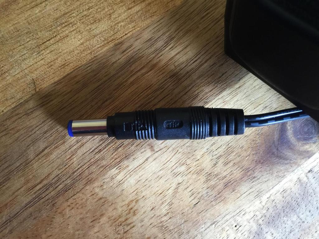
18 18
19 Turn it on Push the I on the power switch. Your LD3 should now turn on. 19
 Morph knob, a Sequencer Morph knob and a volume knob.")
20 The User Interface LD3 has a highly sensitive and responsive capacitive touch display, 16 step/trigger/part select/quick jump buttons, a Morph Set button, a Func/Mute button, a Steps/Part button and a Sequencer Start/Stop button. It has 8 Edit/Quick Edit Knobs for controlling and editing parameters and sending MIDI CC s, a (synth) Morph knob, a Sequencer Morph knob and a volume knob. Pushing the Trigger 1-16 buttons, with Func/Mute and Steps/Part unlit, will trigger the respective LD3 part. Each trigger button will send a settable note number (Settable in the Synth Trig section). When a trigger is trigged, the button will light up. The Start/Stop button will start and stop Sequencer playback. When the sequencer is playing back, the Start/Stop button will light up. The Morph Set button, will toggle the parameters on any Synth and Sequencer page, between 2 layers of parameters, A and B. The Morph knob (MIDI CC#1) will morph between the two layers of Synth parameters, and the Seq Morph knob (MIDI CC#2) will morph between the two layers of Sequencer parameters. 20
21 When the Func/Mute button is held down, it is possible to mute/unmute the 16 note tracks, by pushing any of the 16 step buttons. When it is lighting up, the 16 step buttons functions as Quick Jump buttons, that will take you to the edit pages, which names are showed right above each step button. When the Steps/Part button is held down, the 16 step buttons functions as Part Select buttons. Pushing any of these, will select part 1 to 16. When it is lighting up, the 16 step buttons will show the steps of the selected sequencer note track. Steps that are on will light up, steps that are off will not light. The Volume knob always adjusts the audio output volume. The Edit 1-8 Knobs to the left of the display, adjusts the parameters on each edit page. On the Preset Select screen, they acts as modulation sources, that controls any parameters that has knob1 to 8 set as modulator, and transmits MIDI CC s. Any Edit Knob, that has not been assigned as a modulator to any parameter, acts as a Quick Edit Knob. The Quick Edit Knobs controls: -Edit Knob 1: Digital filter 1 cutoff (MIDI CC#4). -Edit Knob 2: Digital filter 1 resonance (MIDI CC#5). -Edit Knob 3: Digital filter 1 mix (MIDI CC#8). -Edit Knob 4: VCA envelope release time (MIDI CC#9). -Edit Knob 5: Digital filter 2 cutoff (MIDI CC#10). -Edit Knob 6: Digital filter 2 resonance (MIDI CC#11). -Edit Knob 7: Digital filter 2 mix (MIDI CC#12). -Edit Knob 8: The level of the selected part (MIDI CC#7). When the knobs is not assigned to any modulation destinations, they will work as Quick Edit knobs. When they work as Quick Edit knobs, and MIDI CC s are received, these will be received per part. When the Edit Knobs are assigned as modulation sources, to any modulation destination, they will work globally. The Morph knob and the Seq Morph knob will always work globally. 21
22 The Touch Screen Keyboard The LD3 display is touch sensitive. The touch interface is used for navigating through the edit and settings pages, and in the bottom of most pages, a fully playable touch keyboard is present. On the Preset and Song Select pages, it is, besides from playing notes on the touch keyboard, also possible to apply modulation to the sound, by placing your finger on different positions between the top and the bottom of the keyboard. This is referred to as Keyboard Y modulation. On any other pages, the keyboard only plays notes. The touch keyboard is always controlling the selected part. It is possible to select the keyboard octave, by touching any of the 8 squares just above the keyboard. By touching the - and + buttons, just above the keyboard, it is possible to adjust the keyboard size. The size can be from 1 to 8 octaves. 22
23 The Preset Select Screen This is the first screen you will see, right after LD3 s start-up screen, unless you left your LD3 in Song mode, the last time it was turned off. Here you can change preset, jump to LD3 s edit and settings pages, and adjust the touch keyboard settings, as described on the previous pages. On the top of this screen, the Sequencer bar/beat, that is currently being played back, is shown. To the right of the bar/beat indicator, you will find a sequencer record indicator (REC) and a sequencer tempo indicator. When the REC indicator is red, the sequencer are in record mode. Touching the REC indicator, will switch the sequencer in and out of recording mode. Touching the tempo indicator, will make LD3 jump to the sequencer main page, where you can set the tempo. Below the bar/beat indicator, it says Preset, if LD3 is currently in preset mode, or Song if it is currently in song mode. Below this, the number and name of the currently selected preset/song is shown. Below the preset name/number, you will find the touch screen keyboard. Right above the preset name, 8 small VU-meters are shown. These shows the activity of voice 1 to 8. Touch the EDIT field in the upper right corner of the screen, to enter the edit and setup pages. 23
24 Touch the PRESET field, to select a memorized preset. Selecting a preset: Touch the PRESET field. A list of 5 presets near the currently selected preset, will now appear: Touch PREV or NEXT to view the previous or next 5 presets, and finally touch the preset name of the preset you would like to select presets can be selected, from A01 to P64. LD3 will now jump back to the main Preset Select screen, and show the name of the newly selected preset. If the sequencer is playing back, the Start/Stop LED will now start to flash, and the text NEXT: will show right above the new presets name, awaiting track 1 to reach its start/end step. As soon as this happens, LD3 will switch to the newly selected preset, the Start/Stop LED will stop flashing, and NEXT: will dissapear. If the sequencer is not playing back, LD3 will immediately switch to the new preset, when you touch the preset name. When LD3 is turned off, it will remember which preset was selected, and start up with this, when turned on again. It will also remember if it was in preset or song mode, and start up in the same mode, and if it was in song mode, it will also remember which song was selected. 24
25 Presets can also be selected, using the buttons. This is described in the next section Operating LD3. If you activate the PreView mode, by touching the PreView field, so it turns black with white text, you can preview the presets, without LD3 jumping back to the main Preset Select screen. If the sequencer is running, it will still wait for track 1 to reach step 1, until it jumps to the next preset. This is indicated by the Start/Stop LED flashing. 25
26 Operating LD3 Starting and stopping the Sequencer, and trigger parts manually: To start the sequencer playback, push and release the Start/Stop button, so that it lights up. The sequencer will now start to play back. When the Func/Mute and the Steps/part buttons are not lighting up, every time a part is trigged to play back, the corresponding step button will light up shortly. To stop the sequencer, simply hit the Start/Stop button again, so that it is no longer lighting up. To trigger the 16 parts manually, make sure that neither the Func/Mute button or the Steps/Part button is lighting up, and then push any of the 16 step buttons, to trigger the sounds that are programmed on each part. 26
27 Selecting a part: Push and hold the Steps/Part button. The selected part number will now be shown, by one of the 16 step buttons lightning up. The number above the step button, is the part number that is currently selected. To select another part, while still holding down the Steps/Part button, push any of the 16 step buttons. The selected part, is the part which parameters will be shown on the display, when entering the edit pages. Selecting a part, also selects the equally numbered Sequencer Note Track. When entering the Sequencer Controller tracks 1 to 16, track 1 to 16 is selected in the same way. When entering the Sequencer Controller tracks 17 to 32, 1 will equal 17, 2 will equal 18, and so on. Selecting Effects Processors The 8 insert effects processors and the 2 output effects processors are also selected, using the part select buttons. Part 1 is insert effect 1 Part 2 is insert effect 2 Part 3 is insert effect 4 - Part 8 is insert effect 8 Part 9 is output effect 1 Part 10 is output effect 2 27
28 Sequencer Note Track Steps view/edit: First, select the part, for which you would like to view/edit the note steps, as described earlier in this manual. You can, of course, select another part at any time, also after you have entered note step edit mode. To enter note step edit mode, push and release the Steps/Part button. This should now light up. Any note sequencer steps that are switched on to play back, will now also light up on the 16 step buttons. If the sequencer is running, the light state of each step button will be reversed, when a step is playing back. To switch a step on or off, simply hit the corresponding step button, at it will toggle its state. When the sequencer are in recording mode (the Start/Stop button is flashing), pushing any of the step buttons, will set record mode to step mode, and select this step for recording. The step button will now flash. When using the LD3 sequencer as a usual step sequencer, the steps will play back from left to right. In this case, step 1 plays back at position 1, step 2 plays back at position 2 and so on. On the LD3 sequencer, it is though possible to break this pattern, and make each step play back on any position, using the position subtrack. It is even possible to make more steps playing back at the same position, for polyphonic step sequencing. But more on that in the final manual Only 16 steps are shown at a time. The note tracks of LD3 has 64 steps. Please read on, to experience how to switch between step 1-16, 17-32, and
29 Selecting Sequencer Note Track steps 1-16, 17-32, and 49 to 64: Push and release the Func/Mute button, so that it is lightning up. Now, push and release step button 1, Bar Sel: Now step button 1, Bar Sel, will light up. If steps 1-16 are selected, step button 2 will also light up, and step buttons 3, 4 and 5 will flash. To select steps 1 to 16, push step button 2. This will light up, and step button 3, 4 and 5 will flash. To select steps 17 to 32, push step button 3. This will light up, and step button 2, 4 and 5 will flash. To select steps 33 to 48, push step button 4. This will light up, and step button 2, 3 and 5 will flash. To select steps 49 to 64, push step button 5. This will light up, and step button 2, 3 and 4 will flash. After selecting the desired steps, hit the Steps/Part button, to switch steps on and off. At any time, return to the steps select, just by hitting the Func/Mute button. 29
30 Setting the last step of a Note Track This can be done on the Note Tracks edit pages, but it can also be done via the pushbuttons. Push and hold the Morph Set button. If the last step of the selected note track are inside the selected step range, this will now be shown, as a step button that lights up. Push any step button, while still holding down the Morph Set button, to set the last step of the selected Note Track. 30
31 Mute/Unmute Note Tracks: To mute, unmute or view the mute state of the 16 note tracks, push and hold the Func/Mute button. Unmuted tracks will now be shown by a step button that is lighting up, and shortly flashes off, every time the track is triggering. Muted tracks are shown by a step button that is unlit, and that lights up shortly, every time the track would have triggered something, if it weren t muted. To mute or unmute a track, simply hit the corresponding step button, while still holding down the Func/Mute button. 31
32 Copy Morph Layer A to Layer B Push and release the Func/Mute button, so that it lights up, to enter the function buttons. Now push and release step button 13 (Copy), so that this also lights up. Instructions for copy and panic will now be shown on the screen. Push and release the Morph Set button. Morph layer A synth parts and sequencer parameters has now been copied to morph layer B. If you turn the Morph knobs, you should now hear the same sound/sequence, no matter what position the knobs are in. Selecting the next preset Push and hold the Steps/Part button while pressing the Start/Stop button. LD3 will now select the next preset. If the sequencer is playing back, the Start/Stop LED will now start to flash, and the text NEXT: will show right above the new presets name, awaiting track 1 to reach its start/end step. As soon as this happens, LD3 will switch to the newly selected preset, the Start/Stop LED will stop flashing, and NEXT: will dissapear. If the sequencer is not playing back, LD3 will immediately switch to the new preset. 32
33 Selecting the previous preset Push and hold the Steps/Part button while pressing the Morph/Set button. LD3 will now select the previous preset. If the sequencer is playing back, the Start/Stop LED will now start to flash, and the text NEXT: will show right above the new presets name, awaiting track 1 to reach its start/end step. As soon as this happens, LD3 will switch to the newly selected preset, the Start/Stop LED will stop flashing, and NEXT: will dissapear. If the sequencer is not playing back, LD3 will immediately switch to the new preset. 33
34 Selecting Presets using the step buttons Push and hold the Steps/Part button while pressing the Func/Mute button. Now both of these buttons will light up. It is now possible to select the 64 presets in the currently selected preset bank, using the step buttons. Step button 1 to 8 selects the lower digit of the preset number, and step button 9-16 selects the higher digit. When pushing the same button combination again, the Steps/Part button will still light up, while the Func/Mute button will start to flash. It is now possible to select preset bank A to P, using step buttons 1 to 16. Pushing the same button combination yet another time, will exit from the preset select mode. 34
35 Preset Reload / Advance Song realtime record step Push and hold the Morph Set button, while pressing the Start/Stop button, to reload the currently selected preset. While realtime recording a song, reloading the preset, will cause the song recorder to advance to the next song step. This is useful for recording track mutes of the same preset into the song. Panic Push and release the Func/Mute button, so that it lights up, to enter the function buttons. Now push and release step button 13 (Copy), so that this also lights up. Instructions for copy and panic will now be shown on the screen. Push and release step button 16 (Exit). Now all notes, both internally and on any MIDI devices connected to the LD3 MIDI out, will be shutted off. 35
36 Shortcuts to Edit Pages Push and release the Func/Mute button, so that it lights up. Now push and release the step button, that has the name of the edit page over it, that you wish to jump to. When pushing some of these buttons a number of times, it will toggle through a number of pages: Seq Main: Sequencer Main. Note Trk: Notes > Gate time > Velocity > Note Mod. Ctrl Trk: Ctrl Track 1-16 step values > Ctrl Track 1-16 CC > Ctrl Track step values > Ctrl Track CC. Freeze: Freezes any effects, that has Freeze modulation set to Buton. Osc: Osc > Mod > Sel > Smp. Filter: Digital filter 1 > Analog Filter 1 > Analog Filter 2 > Analog Filter 3 > Analog Filter 4. VCA: VCA > Mod. Env: Envelope > Mod. LFO: LFO > Mod. EFX: EFX Select > EFX > Mod. Sample/Qrec: Sample Rec > Starts Quick recording > Stops Quick Recording and saves sampling. Sample/Qrec and then Exit: Sample Edit. Save: Save To Preset select > Save to name 1-8 > Save to name 9-16 > Saving Preset. 36
37 Exit: Exits from any page. 37
38 Audio Bus System Each of the 16 parts in LD3, consists of a sound generator, that can be selected to be either a multi waveform oscillator, a sampler or a noise generator. The audio signal from the sound generator goes into 2 digital multimode filters. The output signal from the filters goes into a VCA. In order to make the sound of the part audible, it must be assigned to one of the 8 audio busses. The audio bus must also be sent to an audio output, or output effects processor 1 or 2. In the VCA section of the part, it is possible to assign the selected part to output to one or two audio busses. When outputting to two audio busses, the output signal from the part will be a stereo signal, and one of the two digital filters will be placed on the left channel, and the other on the right channel. The default settings is that all parts are mono routed to Bus 1. Bus 1 is set to output on the main Left and Right audio jack connectors. On each of the 8 busses, it is possible to place any of the 8 insert effect processors and the analog filters (up to 4, if installed), for processing the sounds, that are sent to the busses. Each audio input can also be routed to any Bus, for realtime processing of external gear through the effects and analog filters. The parameters of the audio busses, the parts and the effects are explained in the next section The Synth/Sampler Parts. The structure of the parts and busses in LD3, are shown on the next page. 38
39 39
40 The Synth/Sampler Parts LD3 has 16 parts, that is playing back through 8 voices, using dynamic allocation. Each part must be set up to output to one or two of the 8 audio busses (see the Audio Bus System section earlier in this manual). Each part has: -1 oscillator. This can play a morphable synth waveform, up to 4 samplings (stereo or mono) or a noise waveform. -2 digital multimode filters with resonance. -1 VCA, where both output level and pan can be adjusted and modulated. -3 envelopes. Two ADSR types and one decay envelope. -4 Random Generators. Always key trigged. -2 Granular Modulators. A random one and a sequenced one. Both are trigged, when a synth waveform or a sampling starts over. Shared between the 16 parts: -16 LFO s with morphable waveforms. Audio busses: The audio output of the parts can be sent to any of 8 audio busses. Each part can output to 2 audio busses at a time. On the audio busses effects and analog filters can be applied, and the audio output of the busses can be sent to the 2 output effects, and to the audio outputs. Remember to save all edits you do in the synth/sampler section. Else they will be lost when you change preset, or turn LD3 off. See how to in the Save Preset section. 40
41 List of Modulation Sources: Env1: The output of ADSR Envelope 1 Env1-: The output of ADSR Envelope 1 Inverted Env2: The output of Decay Envelope 2 Env2-: The output of Decay Envelope 2 Inverted Aenv: The output of the VCA Envelope Aenv-: The output of the VCA Envelope Inverted LFO1: The output of LFO1 LFO1-: The output of LFO1 Inverted LFO2: The output of LFO2 LFO2-: The output of LFO2 Inverted LFO3: The output of LFO3 LFO3-: The output of LFO3 Inverted LFO4: The output of LFO4 LFO4-: The output of LFO4 Inverted LFO5: The output of LFO5 LFO5-: The output of LFO5 Inverted LFO6: The output of LFO6 LFO6-: The output of LFO6 Inverted LFO7: The output of LFO7 LFO7-: The output of LFO7 Inverted LFO8: The output of LFO8 LFO8-: The output of LFO8 Inverted LFO9: The output of LFO9 LFO9-: The output of LFO9 Inverted LFO10: The output of LFO10 LFO10-: The output of LFO10 Inverted LFO11: The output of LFO11 LFO11-: The output of LFO11 Inverted LFO12: The output of LFO12 LFO12-: The output of LFO12 Inverted LFO13: The output of LFO13 LFO13-: The output of LFO13 Inverted LFO14: The output of LFO14 LFO14-: The output of LFO14 Inverted LFO15: The output of LFO15 LFO15-: The output of LFO15 Inverted 41
42 LFO16: The output of LFO16 LFO16-: The output of LFO16 Inverted Rnd1: The output of Part Random Generator 1 Rnd1-: The output of Part Random Generator 1 Inverted Seq1: The output of Sequencer Controller Track 1 Seq1-: The output of Sequencer Controller Track 1 Inverted Seq2: The output of Sequencer Controller Track 2 Seq2-: The output of Sequencer Controller Track 2 Inverted Seq3: The output of Sequencer Controller Track 3 Seq3-: The output of Sequencer Controller Track 3 Inverted Seq4: The output of Sequencer Controller Track 4 Seq4-: The output of Sequencer Controller Track 4 Inverted Seq5: The output of Sequencer Controller Track 5 Seq5-: The output of Sequencer Controller Track 5 Inverted Seq6: The output of Sequencer Controller Track 6 Seq6-: The output of Sequencer Controller Track 6 Inverted Seq7: The output of Sequencer Controller Track 7 Seq7-: The output of Sequencer Controller Track 7 Inverted Seq8: The output of Sequencer Controller Track 8 Seq8-: The output of Sequencer Controller Track 8 Inverted Seq9: The output of Sequencer Controller Track 9 Seq9-: The output of Sequencer Controller Track 9 Inverted Seq10: The output of Sequencer Controller Track 10 Seq10-: The output of Sequencer Controller Track 10 Inverted Seq11: The output of Sequencer Controller Track 11 Seq11-: The output of Sequencer Controller Track 11 Inverted Seq12: The output of Sequencer Controller Track 12 Seq12-: The output of Sequencer Controller Track 12 Inverted Seq13: The output of Sequencer Controller Track 13 Seq13-: The output of Sequencer Controller Track 13 Inverted Seq14: The output of Sequencer Controller Track 14 Seq14-: The output of Sequencer Controller Track 14 Inverted Seq15: The output of Sequencer Controller Track 15 Seq15-: The output of Sequencer Controller Track 15 Inverted Seq16: The output of Sequencer Controller Track 16 Seq16-: The output of Sequencer Controller Track 16 Inverted Seq17: The output of Sequencer Controller Track 17 Seq17-: The output of Sequencer Controller Track 17 Inverted Seq18: The output of Sequencer Controller Track 18 Seq18-: The output of Sequencer Controller Track 18 Inverted 42
43 Seq19: The output of Sequencer Controller Track 19 Seq19-: The output of Sequencer Controller Track 19 Inverted Seq20: The output of Sequencer Controller Track 20 Seq20-: The output of Sequencer Controller Track 20 Inverted Seq21: The output of Sequencer Controller Track 21 Seq21-: The output of Sequencer Controller Track 21 Inverted Seq22: The output of Sequencer Controller Track 22 Seq22-: The output of Sequencer Controller Track 22 Inverted Seq23: The output of Sequencer Controller Track 23 Seq23-: The output of Sequencer Controller Track 23 Inverted Seq24: The output of Sequencer Controller Track 24 Seq24-: The output of Sequencer Controller Track 24 Inverted Seq25: The output of Sequencer Controller Track 25 Seq25-: The output of Sequencer Controller Track 25 Inverted Seq26: The output of Sequencer Controller Track 26 Seq26-: The output of Sequencer Controller Track 26 Inverted Seq27: The output of Sequencer Controller Track 27 Seq27-: The output of Sequencer Controller Track 27 Inverted Seq28: The output of Sequencer Controller Track 28 Seq28-: The output of Sequencer Controller Track 28 Inverted Seq29: The output of Sequencer Controller Track 29 Seq29-: The output of Sequencer Controller Track 29 Inverted Seq30: The output of Sequencer Controller Track 30 Seq30-: The output of Sequencer Controller Track 30 Inverted Seq31: The output of Sequencer Controller Track 31 Seq31-: The output of Sequencer Controller Track 31 Inverted Seq32: The output of Sequencer Controller Track 32 Seq32-: The output of Sequencer Controller Track 32 Inverted Kybd: The last note number value received for the part Kybd-: The last note number value received for the part Inverted Velo: The last note velocity value received for the part Velo-: The last note velocity value received for the part Inverted Maft: The last mono aftertouch value received for the part Maft-: The last mono aftertouch value received for the part Inverted Bnd: The last pitch bend value received for the part Bnd-: The last pitch bend value received for the part Inverted K1C4: Edit knob 1 value or the last MIDI CC 4 value received K1C4-: Edit knob 1 value or the last MIDI CC 4 value received Inverted K2C5: Edit knob 2 value or the last MIDI CC 5 value received K2C5-: Edit knob 2 value or the last MIDI CC 5 value received Inverted 43
44 K3C7: Edit knob 3 value or the last MIDI CC 8 value received K3C7-: Edit knob 3 value or the last MIDI CC 8 value received Inverted K4C8: Edit knob 4 value or the last MIDI CC 9 value received K4C8-: Edit knob 4 value or the last MIDI CC 9 value received Inverted TouY: Touch screen keyboard Y-axis position TouY-: Touch screen keyboard Y-axis position Inverted GrRn: Granular Random Modulator GrRn-: Granular Random Modulator Inverted GrSq: Granular Sequenced Modulator GrSq-: Granular Sequenced Modulator Inverted CV1: The voltage applied to CV Input 1 CV1-: The voltage applied to CV Input 1 Inverted CV2: The voltage applied to CV Input 2 CV2-: The voltage applied to CV Input 2 Inverted CV3: The voltage applied to CV Input 3 CV3-: The voltage applied to CV Input 3 Inverted CV4: The voltage applied to CV Input 4 CV4-: The voltage applied to CV Input 4 Inverted Flw1: The Audio Bus 1 Envelope Follower Flw1-: The Audio Bus 1 Envelope Follower Inverted Flw2: The Audio Bus 2 Envelope Follower Flw2-: The Audio Bus 2 Envelope Follower Inverted Flw3: The Audio Bus 3 Envelope Follower Flw3-: The Audio Bus 3 Envelope Follower Inverted Flw4: The Audio Bus 4 Envelope Follower Flw4-: The Audio Bus 4 Envelope Follower Inverted Flw5: The Audio Bus 5 Envelope Follower Flw5-: The Audio Bus 5 Envelope Follower Inverted Flw6: The Audio Bus 6 Envelope Follower Flw6-: The Audio Bus 6 Envelope Follower Inverted Flw7: The Audio Bus 7 Envelope Follower Flw7-: The Audio Bus 7 Envelope Follower Inverted Flw8: The Audio Bus 8 Envelope Follower Flw8-: The Audio Bus 8 Envelope Follower Inverted Knb5: Edit knob 5 value or the last MIDI CC 10 value received Knb5-: Edit knob 5 value or the last MIDI CC 10 value received Inverted Knb6: Edit knob 6 value or the last MIDI CC 11 value received Knb6-: Edit knob 6 value or the last MIDI CC 11 value received Inverted Knb7: Edit knob 7 value or the last MIDI CC 12 value received Knb7-: Edit knob 7 value or the last MIDI CC 12 value received Inverted 44
45 Knb8: Edit knob 8 value or the last MIDI CC 7 value received Knb8-: Edit knob 8 value or the last MIDI CC 7 value received Inverted Trig: The trigger output of the part Trig-: The trigger output of the part Inverted Rnd2: The output of Part Random Generator 2 Rnd2-: The output of Part Random Generator 2 Inverted Rnd3: The output of Part Random Generator 3 Rnd3-: The output of Part Random Generator 3 Inverted Rnd4: The output of Part Random Generator 4 Rnd4-: The output of Part Random Generator 4 Inverted CC17: The last MIDI CC 17 value received CC17-: The last MIDI CC 17 value received Inverted CC18: The last MIDI CC 18 value received CC18-: The last MIDI CC 18 value received Inverted CC19: The last MIDI CC 19 value received CC19-: The last MIDI CC 19 value received Inverted CC20: The last MIDI CC 20 value received CC20-: The last MIDI CC 20 value received Inverted CC21: The last MIDI CC 21 value received CC21-: The last MIDI CC 21 value received Inverted CC22: The last MIDI CC 22 value received CC22-: The last MIDI CC 22 value received Inverted CC23: The last MIDI CC 23 value received CC23-: The last MIDI CC 23 value received Inverted CC24: The last MIDI CC 24 value received CC24-: The last MIDI CC 24 value received Inverted CC25: The last MIDI CC 25 value received CC25-: The last MIDI CC 25 value received Inverted CC26: The last MIDI CC 26 value received CC26-: The last MIDI CC 26 value received Inverted CC27: The last MIDI CC 27 value received CC27-: The last MIDI CC 27 value received Inverted CC28: The last MIDI CC 28 value received CC28-: The last MIDI CC 28 value received Inverted CC29: The last MIDI CC 29 value received CC29-: The last MIDI CC 29 value received Inverted CC30: The last MIDI CC 30 value received CC30-: The last MIDI CC 30 value received Inverted CC31: The last MIDI CC 31 value received CC31-: The last MIDI CC 31 value received Inverted 45
46 CC33: The last MIDI CC 33 value received CC33-: The last MIDI CC 33 value received Inverted CC34: The last MIDI CC 34 value received CC34-: The last MIDI CC 34 value received Inverted CC35: The last MIDI CC 35 value received CC35-: The last MIDI CC 35 value received Inverted CC36: The last MIDI CC 36 value received CC36-: The last MIDI CC 36 value received Inverted CC37: The last MIDI CC 37 value received CC37-: The last MIDI CC 37 value received Inverted CC38: The last MIDI CC 38 value received CC38-: The last MIDI CC 38 value received Inverted CC39: The last MIDI CC 39 value received CC39-: The last MIDI CC 39 value received Inverted CC40: The last MIDI CC 40 value received CC40-: The last MIDI CC 40 value received Inverted CC41: The last MIDI CC 41 value received CC41-: The last MIDI CC 41 value received Inverted CC42: The last MIDI CC 42 value received CC42-: The last MIDI CC 42 value received Inverted CC43: The last MIDI CC 43 value received CC43-: The last MIDI CC 43 value received Inverted CC44: The last MIDI CC 44 value received CC44-: The last MIDI CC 44 value received Inverted CC45: The last MIDI CC 45 value received CC45-: The last MIDI CC 45 value received Inverted CC46: The last MIDI CC 46 value received CC46-: The last MIDI CC 46 value received Inverted CC47: The last MIDI CC 47 value received CC47-: The last MIDI CC 47 value received Inverted CC48: The last MIDI CC 48 value received CC48-: The last MIDI CC 48 value received Inverted CC49: The last MIDI CC 49 value received CC49-: The last MIDI CC 49 value received Inverted CC50: The last MIDI CC 50 value received CC50-: The last MIDI CC 50 value received Inverted CC51: The last MIDI CC 51 value received CC51-: The last MIDI CC 51 value received Inverted CC52: The last MIDI CC 52 value received CC52-: The last MIDI CC 52 value received Inverted 46
47 CC53: The last MIDI CC 53 value received CC53-: The last MIDI CC 53 value received Inverted CC54: The last MIDI CC 54 value received CC54-: The last MIDI CC 54 value received Inverted CC55: The last MIDI CC 55 value received CC55-: The last MIDI CC 55 value received Inverted CC56: The last MIDI CC 56 value received CC56-: The last MIDI CC 56 value received Inverted CC57: The last MIDI CC 57 value received CC57-: The last MIDI CC 57 value received Inverted CC58: The last MIDI CC 58 value received CC58-: The last MIDI CC 58 value received Inverted CC59: The last MIDI CC 59 value received CC59-: The last MIDI CC 59 value received Inverted CC60: The last MIDI CC 60 value received CC60-: The last MIDI CC 60 value received Inverted CC61: The last MIDI CC 61 value received CC61-: The last MIDI CC 61 value received Inverted 47
48 Accessing The Synth Part Pages From the Preset/Song Select screen, Touch the EDIT field. 48
49 Now LD3 will show the main Synth page: In the top of the main Synth page, you will find the 6 main edit groups and the ESC (escape) touch button. Touch any of these group buttons to access them, and touch ESC, to exit to the Preset Select page. The touch button of the currently selected edit group is brown/yellow, while the buttons of the other groups are green. The group of touch buttons, will be reffered to as the group select bar. Below the group select bar, you will find the synth blocks. Touch any block, to access the parameters of it, and edit these. Part 1 to 16 is selected using the Steps/Part button in combination with the step buttons. In the bottom of this page, the touch keyboard is located. The Synth Part pages can also be accessed, using pushbutton shortcuts. This is explained on page 36 of this manual. 49
50 Editing The Parameters Of The Synth Part Blocks Each edit page has up to 8 parameters, that can be edited. The parameters are shown on the display as 8 parameter names, each with an alphanumeric value below them, that shows the current value of the parameter. When turning any of the 8 Edit Knobs, the corresponding parameter will be adjusted, and you will hear a change in the sound, if the block is active. Right below the parameters, you will find the subpage select touch buttons. Touch any of these, to access the desired parameter sub page. The touch button that is black with white text, shows that this is the currently selected sub page. The grey touch buttons, are the sub pages, that you can select. In the top of the display, it is, on the part edit pages, possible to see what part slot that is currently selected. In the upper right corner of each block you will find EXIT. Touch this to exit to the main Synth page. 50
51 The Synth Part Blocks In this section of the manual, you will find a description of the parameters of each part, and the parameters related to the LFO s the effects processors and the BUS system. The Synth Part Parameters Randomizer If you should ever need some new inspiration for sounds, or if you just want to surprise yourself with some sounds that you never even imagined, the LD3 parameter randomizer might be exactly what you need. To enter this, from the synth parts main page, touch RNDM. 51
52 You should now enter this page: Select the part that you would like to randomize, in the same way as you would usually select a part, by pushing and holding the Steps/Part button, while pressing one of the 16 step buttons. Switch the blocks on, that you would like to randomize, simply by touching these, adjust the percentage, that it must maximum change the parameters, using Edit Knob 1, and hit DO!. Green blocks are not randomized, brown blocks are. Listen to the result. If you like it, exit the randomizer page, and save the preset. If you don t like the result, hit DO! again, and keep hitting it, until something comes up, that you like. Try with different percentage settings, and try to switch different blocks on and off. When the Randomizer page is entered, all parameters are stored into a temporary buffer, that are used for the randomization. So if you, for instance, first randomizes with 50%, and then with 20%, the result will be maximum 20% away from the initial parameter settings, when the Randomizer page was entered. It does not first randomize 50%, and then randomize 20% on top of that. To randomize things further away, you must exit the Randomizer page, and re-enter it. 52
53 Synth Part Trigger Setup In this block, you can set up the poly mode of each part, the pitch bend range, the note that will play pack, when pushing a trigger button, and if the part should be an internal or an external part. From the synth parts main page, touch TRIG to enter this page. Mode: Part polyphonic/monophonic mode. Choices are: Poly: The part uses multiple voices, to play back polyphonically. MonoToVoice1-8: The part plays back monophonically, and only uses the one voice, that it is assigned to. Other parts that are in poly mode, does not use this voice. It can oly be cutted off, by another part that is set to mono to the same voice. Use this mode, when playing back long samples and audio tracks without chops, and if you got some parts, that should cut each other off, like parts that are playing back closed and open hihats. TriggerNote: C-1 to G9. The note that should play, when the step buttons are in trigger mode (when both the Func/Mute button and the Steps/Part button are unlit), and you push the trigger button, for this part. Bend Range: 0 to 12 notes. The global pitch bend range for all parts. 53
54 Chan: 1 to 16. The part output MIDI channel. This will also affect the part Sequencer Note Track. When the part is set to external, this is the MIDI channel that note data played by the trigger button, the touchscreen keyboard, on an attached MIDI device, and from the part sequencer note track are sent on, to the LD3 MIDI out. Int/Ext: Sets the part in internal (Int) or external (Ext) mode. When a part is set to internal mode, all notes played by the part trigger button, the touchscreen keyboard, on an attached MIDI device, and from the part sequencer note track, controls the internal LD3 synth part. When a part is set to external mode, all notes played by the part trigger button, the touchscreen keyboard, on an attached MIDI device, and from the part sequencer note track, controls any MIDI device, that is connected to the LD3 MIDI output, and that is set to the same MIDI channel, as set by the Chan parameter on this page. 54
55 Zone Setup In this block, it is possible to set up a key zone and a MIDI channel for the part, that will take effect, when LD3 is set in multi-timbral mode, and is controlled from an external MIDI device. How to set LD3 in multi-timbral mode are explained later in this manual, in the MOR>Common section. From the synth parts main page, touch ZONE to enter this page. LowK1: C-1 to G9. The lowest key of the part zone. HiK1: C-1 to G9. The highest key of the part zone. Trps1: -64 to +63. The incoming MIDI notes, inside the key zone, are transposed up(+) or down(-), by the selected value. Chan1: 1 to 16. The MIDI channel that will control this part. 55
56 Audio BUS Setup In this block, you will find the settings for the 8 audio busses. Please note that these settings are not part specific, but global for the 8 busses and 16 parts. From the synth parts main page, touch TRIG to enter this page. Touch the Out touch button, to enter this first page, where you can select the output, which the audio signal from each of the 8 busses, should be sent to. Possibilities are: L: The output of the Bus is sent to the left audio output. R: The output of the Bus is sent to the right audio output. L+R: The output of the Bus is sent to the left and the right audio outputs. EFX1: The output of the Bus is sent to Output effect 1. EFX2: The output of the Bus is sent to Output effect 2. 3: The output of the Bus is sent to the optional audio output 3. 4: The output of the Bus is sent to the optional audio output 4. 5: The output of the Bus is sent to the optional audio output 5. 6: The output of the Bus is sent to the optional audio output : The output of the Bus is sent to the optional audio outputs 3 and : The output of the Bus is sent to the optional audio outputs 5 and 6. 56
57 Off: The output of the Bus is not sent anywhere. PLEASE NOTE: Audio busses that are assigned to be placed inside an output effect feedback loop, will ignore this setting, and only output to the effect feedback input. 57
58 Touch the Frl touch button, to enter this second audio Bus page, where it is possible to adjust the release time of the envelope follower, that are attached to each audio Bus, and that affects the output levels of these. When this is set to 511, the follower will never decay. When set to lower values, the follower will gradually decay, in accordance with the levels of the audio signal sent to it, from the synth parts. The envelope followers are sent to the modulation system (Flw1 to Flw8), and can be selected as modulation sources, for many parameters. 58
59 Touch the Fga touch button, to enter this third audio Bus page, where it is possible to gain or attenuate the level of the audio signal sent to the Bus envelope follower. At +0, there are no gaining or attenuation. At positive values the signal to the follower is gained, at negative values, they are attenuated. 59
60 Touch the Flv touch button, to enter this fourth audio Bus page, where it is possible to adjust the total output level of each Bus. Positive values will gain the output signal, negative values will attenuate. 60
61 Touch the Env touch button, to enter this fifth and last audio Bus page, where it is possible to assign any of the 16 part VCA envelopes to control the Bus output level, instead of the attached envelope follower. 61
62 Oscillator/Sampler/Noise Generator In this block, you will find the settings for the part oscillator. From the synth parts main page, touch OSC to enter this page. OR: Push and release the Func/Mute button, so that it lights up, and push step button 6/Osc 1 time. The oscillator are the first block in the audio chain of a part. This is responsible for generating the basic sound of each part, that can be modulated, filtered and effected, for shaping a sound. An LD3 oscillator can be set to act as an oscillator, a sample player or a noise generator. In oscillator mode it generates a waveform that is morphable between sine, triangle, saw, pulse and feedback waves. Pulse width are adjustable for all waveform types. FM (frequency modulation) is possible, with any audio bus as the modulation source. Pitch, PW, wave and FM amount can be modulated. The pitch range of the oscillators are chromatically over the entire 10 octave MIDI keyboard range. In sampler mode it plays back any of the storable samplings, that can either be recorded on LD3 itself in the Sample Rec section, or be imported in the USB section. Each part sampler has 4 sample slots, that each can contain one sampling. Switching between the 4 samplings is done via 62
63 the Chop parameter. Pitch, chop, start point and FM amount can be adjusted and modulated, Length can be adjusted. Samples are chromatically tuned, and has a pitch range of 4 octaves above and 5 octaves below the original sample pitch. Loop mode can be set to Off, On, toggle, sustain, off(unchopped) and on(unchopped). In off and on modes, it will always use the sample chop point, if any. In toggle mode, the looped sample playback will start, when you push and release a trigger button, and stop when you push and release the same trigger button again. In sustain mode, it will play the sampling back from the start point, until it reaches the second chop point. Then it will loop back to the first chop point, and keep looping between these 2 points. When importing a wav sampling with loop points set as cue points, these cue points are imported to the first 2 chop points. In off and on (unchopped) modes, the whole sampling will play back, ignoring any chop points. It is possible to create chop points in the LD3 sample editor, and use these. Chops can be detected by level peaks, by single wavecycles, and by dividing the sample length with a settable number. Chop points will also be imported from wav files, containing these as cue points. Portamento control is provided in both oscillator and sampler mode. In noise generator mode, the oscillator puts out a noise waveform. Pitch and pw (intensity) can be set and modulated. 63
64 Oscillator parameters The OSC page, when in oscillator mode: In the middle of the oscillator page, the currently generated waveform is shown. Touch the buttons named OSC, MOD, SEL and SMP, to enter other oscillator pages, like Modulation and oscillator/sampler/noise mode select. OR: Push and release the Func/Mute button, so that it lights up, and push step button 6/Osc to toggle between these pages. Tune: Adjust the basic pitch in semitones. Range: -64 to Fine: Fine tuning of the pitch. Range: -256 to Wave: This parameter lets you morph between sine, triange, saw, pulse and feedback waves. PW: Adjusts the pulse width of the waveform. Unlike many other oscillator designs, the pulse width can be adjusted on all of LD3 s waveforms, not just the pulse wave. FM: FM amount. The more this is turned up, the more a selected audio bus (in the SEL section) will modulate the pitch of the oscillator. Range: 0 to
65 Porta: Portamento. The more this is turned up, the slower the oscillator pitch will slide from one note to another. Range: 0 to 511. The OSC page, when in Sampler mode: In the bottom of the sampler page, the selected samplings waveform is shown in rough graphics. When the sample, or part of it, is played back, the small black line below the waveform will show the current playback point. Tune: Adjust the basic pitch in semitones. Range: -64 to Fine: Fine tuning of the pitch. Range: -256 to Start: The sample start point. Selects at what point the sample will start to play back, when it is triggered. Range: 0 to 511, stretching over the whole sampling. Length: Sets how much of the sampling should be played back. Range: 0 to 511, stretching over the whole sampling. 65
66 Loop: Sets the sampling loop mode. Off: The sample will not loop, just play back one time from the adjusted, or chop selected, start to end, and then stop. If the selected sampling has chop points, these will always be used. On: The sample will play back from the adjusted start point, when triggered. When it reaches the adjusted end point, it will loop back to the start point, and play back the sample over and over again. If the selected sampling has chop points, these will always be used for the loop points. Toggle: The looped sample playback will start, when you push and release a trigger button, and stop when you push and release the same trigger button again. Sust: When you hit a key, playback of the sampling starts at the sample startpoint. When the playback reaches the endpoint of the selected chop, it loops back to the chop startpoint, and keeps looping between the chop start and end point, until a key is pressed again. OfUc: Off, unchopped. The sample will not loop, just play back one time from the adjusted start to end, and then stop. Chop points will be ignored. OnUc: On, unchopped. The sample will play back from the adjusted start point, when triggered. When it reaches the adjusted end point, it will loop back to the start point, and play back the sample over and over again. Chop points will be ignored. Chop: If chop points has been generated for the selected sampling, a chop can be selected by setting this parameter. If the #Smp parameter on the SEL page is set to 2 or 4 samplings, this parameter will also select which of the 2 or 4 samplings, that will play back, and the chop points for smaple 2 to 3. Range: 0 to 63 for sample 1, 64 to 128 for sample 2, 129 to 192 for sample 3, 193 to 255 for sample 4. #Chp: The number of Chops to be played back in a row. Range: 1 to 64. FM: FM amount. The more this is turned up, the more the selected FM bus (in the SEL section) will modulate the pitch of the sampler. Range: 0 to
67 Oscillator modulation The MOD page, when in oscillator mode: The small VU-meters next to the parameters, shows the activity of the selected modulation sources. For each parameter, that can be modulated, it is possible to select a modulation source, and to adjust the modulation amount. For a complete list of modulation sources, see the list in the start of this section. The upper row of parameters selects the modulation sources, The lower row of parameters (Labelled Amt) adjusts the modulation amount in the range 0 to 511. The parameters on this page: Pitc: Modulates the oscillator pitch. Wave: Modulates the wave select morphing. PWM: Modulates the pulse width of the waveform FM: Modulates the FM amount. 67
68 The MOD page, when in sampler mode: The small VU-meters next to the parameters, shows the activity of the selected modulation sources. For each parameter, that can be modulated, it is possible to select a modulation source, and to adjust the modulation amount. For a complete list of modulation sources, see the list in the start of this section. The upper row of parameters selects the modulation sources, The lower row of parameters (Labelled Amt) adjusts the modulation amount in the range 0 to 511. The parameters on this page: Pitc: Modulates the sampler pitch. Chop: Modulates the Chop number select, and sample select if #Smp is set to 2 or 4. Start: Modulates the sample start point. FM: Modulates the FM amount. 68
69 Oscillator/Sampler/Noise mode select Touch the SEL button, to enter this page. OR: Push and release the Func/Mute button, so that it lights up, and push step button 6/Osc 3 times. Xfade: Sample fade mode. Only affects sample playback. Off: No fading are applied to sample playback. On: When playing back a sampling, both fade in and fade out will be applied. Especially effective, to obtain click free audio track playback. Out: When playing back a sampling, fade out will be applied, to remove clicks at the sample end. Smth: Smoothing. The moment that a sampling loops, the transition from the loop end to the loop start will be smoothed out, to minimize clicks. FmBus: Sets the FM source audio bus for the oscillator/sampler frequency modulation. FM amount is set on the OSC page. Audio bus 1 to 8 can be selected. Porta: Sampler Portamento. The more this is turned up, the slower the sampler pitch will slide from one note to another. Range: 0 to 511. Mode: Selects whether the part oscillator should act as an oscillator (Osc), a sampler (Smp), or a noise generator (Nois). #Smp: Number of samplings. Sets if the part should use 1, 2 or 4 samplings. The 4 samplings are selected on the SMP page, and the samplings can be selected, using the Chop parameter on the sampler OSC page. 69
70 TrgTo: Off, 1 to 16. Makes this part trigger another part. If set to this part, the part will double trigger. The TrLen parameter must be higher than 0, to trigger. TrDly: 0 to 511. Trigger delay. Will add a delay, before it triggers the other part, if set to any other values than zero. TrLen: 0 to 511. Trigger length. Sets how long the extra trigger gate should be. If set to zero, it might not trigger. 70
71 Part Samples Select Touch the SMP button, to enter this page. OR: Push and release the Func/Mute button, so that it lights up, and push step button 6/Osc 4 times. Here you can select 4 samplings for the part. The number of these samplings, that are used, is set by the #Smp parameter on the SEL page. The 4 samples can be selected to play back, setting the Chop parameter, and by chop select modulation. 71
72 To select a sampling for any of the 4 slots, simply touch the sample name. Now this page will pop up: On each page you will view 16 of the samplings, that are held in the LD3 FLASH memory, Bank A, B, C or D. Touch A, B, C and D to select the sample bank, touch PREV and NEXT to view the previous or next 16 samplings. To select a sampling, touch the sample name. A small red square is shown near the sample name of the sampling, that are the last one, that was added to the bank. When you have found the right sampling, touch OK to return to the Synth Part Sample Select page. 72
73 The Granular Modulators Each of the 16 synth parts of LD3 has 2 granular modulators, the granular random generator and the granular sequence modulator, that shows as modulation sources, to any parameter that can be modulated. GrRn Granular Random Generator This works in conjunction with the part oscillator, sampler or noise generator. When in oscillator or noise mode: Every time the synth waveform starts over, the granular random generator puts out a new random value. When modulating the oscillator wave parameter with this, it will randomly glue different waveforms together, for granular chaos. Since any parameter can be modulated by this, the possibilities are endless. When in sampler mode: Every time the sampler loops, the granular random generator will put out a new random value. If you have a wave chopped sampling, and set this parameter up to modulate the chop select parameter, granular random sample chaos will be obtained. Of course, this can also modulate any other parameter, for infinite possibilities. GrSq Granular Sequence Modulator This works in conjunction with the part oscillator, sampler or noise generator, and a Sequencer Controller track. It does not use the output of the controller track directly, only the step values and the last step parameter. The oscillator of part 1 uses controller track 17 for sequence values, part 2 uses controller track 18, part 3 uses controller track 19 and so on When in oscillator or noise mode: Every time the synth waveform starts over, the granular sequence modulator gets the next value from the associated controller track. When modulating the oscillator wave parameter with this, it is possible to program wave sequences. Since any parameter can be modulated by this, the possibilities are endless. 73
74 When in sampler mode: Every time the sampler loops, the granular sequence modulator gets the next value from the associated controller track. If you have a wave chopped sampling, and set this parameter up to modulate the chop select parameter, it is possible to program wave sequences. Of course, this can also modulate any other parameter, for infinite possibilities. 74
75 4 Random Generators Each synth part of LD3 has 4 random generators, that takes in a new random value, every time the part is trigged. There are no settings to be made for these. They are found as modulation sources, named: Rnd1, Rnd2, Rnd3 and Rnd4. 75
76 The Digital Filters Each LD3 part has 2 digital filters. For each of these, 16 different filter types can be selected. They have various lowpass, highpass and bandpass modes, with different characteristics, but also special modes like Lo-Fi, destruktion and Fat. They can be connected in serial or parallel to each other, work as one stereo filter, and their parameters can be linked to each other, for easier tweaking in stereo mode. When different filter types are selected for Morph Layer A and B, LD3 will morph between the filter types. For extra filtering, the same filters are available as insert effects. The filters in the effect processors does though not morph between different filter types. 76
77 List of Digital Filter Types: LPF1: Lowpass filter with a rather weak character. Resonance does not self-oscillate. LPF2: Lowpass filter that are a bit sharper than LPF1. Resonance does not self-oscillate. LPF3: Sharp Lowpass filter with self-oscillating resonance. LPF4: Very sharp Lowpass filter with self-oscillating resonance. BPF1: Bandpass filter with a rather weak character. Resonance does not self-oscillate. BPF2: Bandpass filter with focus on the bass area. Distorts at higher input levels. Resonance does not self-oscillate. BPF3: Sharp Bandpass filter with self-oscillating resonance. HPF1: Sharp Highpass filter with self-oscillating resonance. HPF2: High gained Highpass filter with self-oscillating resonance. Distorts at higher input levels. HPF3: Sharp Highpass filter with self-oscillating resonance. A bit weaker than HPF1. Dstr: Destruktion. A rather defective filter. Self-oscillates at some points, distorts at others. FAT1: Slightly distorting lowpass filter, with a sharp response and self-oscillating resonance. FAT2: A slightly weaker version of FAT1. LoFi: A very distorting and unpredictable lowpass filter. LPF5: A lowpass filter with a very soft character. Resonance does not self-oscillate. BPF4: A bandpass filter with a very soft character and self-oscillating resonance. 77
78 Digital Filters Parameters From the synth parts main page, touch FLT to enter the digital filters. OR: Push and release the Func/Mute button, so that it lights up, and push step button 7/Filter 1 time. Touch the FL1 touch button, to enter the Filter 1 page. Cut: 0 to 511. Sets the cutoff frequency of the filter. Reso: 0 to 511. Sets the amount of resonance applied to the filter. Inp: 0 to 511. Sets the audio signal input level to the filter. Different characteristics can be obtained by adjusting this. Mix: -256 to Sets the mix between the audio input signal and the filter output signal. At +0 the input signal is passed through. At positive values, the the filter output is added to the input signal. At negative values, an inverted version of the filter output is added to the input signal. At +255 and -256 only the output of the filter is heard. Type: Sets the filter type. See the list of filter types. 78
79 Nrw: 0 to 511. Turning this up, will make the frequency response of the filter more and more narrow. Low: 0 to 511. Sets the lowest frequency offset point of the filter. Turning this up, will in many filter types, make the bass bottom more present or distorted. Boost: 0 to 511. Gains the filter output level. 79
80 Filter 1 Modulation Touch the MO1 touch button, to enter the Filter 1 Modulation page. The small VU-meters next to the parameters, shows the activity of the selected modulation sources. For each parameter, that can be modulated, it is possible to select a modulation source, and to adjust the modulation amount. For a complete list of modulation sources, see the list in the start of this section. Cut1, Cut2: Will modulate the filter cutoff frequency. Reso: Will modulate the amount of resonance applied to the filter. Mix: Will modulate the filter Mix. 80
81 Filter 2 Touch the FL2 touch button, to enter the Filter 2 page. Cut: 0 to 511. Sets the cutoff frequency of the filter. Reso: 0 to 511. Sets the amount of resonance applied to the filter. Inp: 0 to 511. Sets the audio signal input level to the filter. Different characteristics can be obtained by adjusting this. Mix: -256 to Sets the mix between the audio input signal and the filter output signal. At +0 the input signal is passed through. At positive values, the the filter output is added to the input signal. At negative values, an inverted version of the filter output is added to the input signal. At +255 and -256 only the output of the filter is heard. Type: Sets the filter type. See the list of filter types. Nrw: 0 to 511. Turning this up, will make the frequency response of the filter more and more narrow. 81
82 Low: 0 to 511. Sets the lowest frequency offset point of the filter. Turning this up, will in many filter types, make the bass bottom more present or distorted. Boost: 0 to 511. Gains the filter output level. 82
83 Filter 2 Modulation Touch the MO2 touch button, to enter the Filter 2 Modulation page. The small VU-meters next to the parameters, shows the activity of the selected modulation sources. For each parameter, that can be modulated, it is possible to select a modulation source, and to adjust the modulation amount. For a complete list of modulation sources, see the list in the start of this section. Cut1, Cut2: Will modulate the filter cutoff frequency. Reso: Will modulate the amount of resonance applied to the filter. Mix: Will modulate the filter Mix. 83
84 Filters Setup Touch the SET touch button, to enter the Filters Setup page. Stereo: Off, On. When off, the left and the right audio signals, coming from the oscillators (only really effective, when stereo samplings are played back), are mixed to one mono signal, that goes through both filters. When on, filter 1 affects only the left channel of the audio signal, and filter 2 affects only the right. Conn: Filters connection parallel (Par) or serial (Ser). Link: Off, On. When on, any setting made on filter 1, is automatically performed on filter 2 too. Can be useful for stereo performance. 84
85 VCA The VCA is the last stage of a synth part, before the audio is sent to the Audio Bus system. The audio output from the digital filter, goes into the VCA. The VCA s can behave in 4 different modes. Linear, logarithmic, smooth linear and smooth logarithmic. The smooth VCA modes behaves like the VCA s found in most other synthesizers. The audio output of the VCA can be level modulated and panned. Pan can also be modulated. The output of the VCA can be sent to 2 audio busses at the same time. When set up like this, the pan control/modulation, is panning the audio signal between the 2 audio busses. For a stereo panned output, one of these busses must be set to the right audio output, and the other to the left. It is also possible to send one bus to output effect 1, and the other to output effect 2. Then the pan control/modulation will mix between the 2 effects. Of course, filters and insert effects can also be placed on these busses, for more sonic possibilities. An ADSR envelope are attached to the VCA. The VCA envelopes can either be in linear or logarithmic mode. A Drone parameter are available, for opening the VCA without the envelope needing to be trigged. VCA output level are modulated by the attached ADSR envelope. Attack and release can be modulated by any modulation source. 85
86 VCA Parameters From the synth parts main page, touch VCA to enter the VCA pages. OR: Push and release the Func/Mute button, so that it lights up, and push step button 8/VCA 1 time. Touch the VCA touch button, to enter the VCA parameters page. The VU-meter at the right of the screen, shows the VCA output activity. A: 0 to 511. VCA envelope attack time. The time it will take the VCA envelope to rise from zero to its maximum value, when a note event is received and held down. D: 0 to 511. VCA envelope decay time. When the VCA envelope has reached its maximum value, in the time set by the attack parameter, it will decay, until it reaches the sustain level, and stay there, as long as the note that trigged it is held. S: 0 to 511. VCA envelope sustain level. Explained under the D parameter. R: 0 to 511. VCA envelope release time. The time it will take the VCA envelope to decay from the value it is at, when a note off event are received, to zero. 86
87 Bus: 1/2, 3/4, 5/6, 7/8, 1, 2, 3, 4, 5, 6, 7, 8. Selects to which Audio Bus(ses) the VCA should output its audio to. When 2 busses are selected, the pan parameter and modulation, pans the audio signal between the 2 busses. Mode: Selects if the VCA behaviour should be linear (Lin), logarithmic (Log), smooth linear (LinSM) or smooth logarithmic (LogSM). The logarithmic curve gives the sound a softer and less clicky attack. The smooth modes produces no clicking at all. Drone: 0 to 511. VCA envelope drone offset level. When this is turned up, the VCA envelope will never reach an output value, lower than what this is adjusted to It will release to this adjusted value, instead of zero. Use this to keep the output of a synth part open for drone sounds. Level: The VCA output level. 87
88 VCA Modulation Touch the MOD touch button, to enter the VCA modulation page. OR: Push and release the Func/Mute button, so that it lights up, and push step button 8/VCA 2 times. The VU-meter at the right of the screen, shows the VCA output activity. The small VU-meters next to the parameters, shows the activity of the selected modulation sources. For each parameter, that can be modulated, it is possible to select a modulation source, and to adjust the modulation amount. For a complete list of modulation sources, see the list in the start of this section. A: Modulates the VCA Envelope attack time. R: Modulates the VCA Envelope release time. Level: Modulates the output level of the VCA. Pan: Modulates the output panning of the VCA. When source is set to manual ( Man ), the amount parameter manually adjusts the output panning. 88
89 Envelope 1 and 2 Each Synth part of LD3 has 2 modulation envelopes. One ADSR type, and one decay only envelope. Envelope 1, the ADSR envelope can have linear or logarithmic charateristics and it also has an offset control. Envelope 2, the decay envelope, is always linear. 89
90 Envelope 1 and 2 Parameters From the synth parts main page, touch ENV to enter the envelope pages. OR: Push and release the Func/Mute button, so that it lights up, and push step button 9/Env 1 time. Touch the ENV touch button, to enter the envelope parameters page. The VU-meter at the right of the screen, shows the Envelope output. A: 0 to 511. Envelope 1 attack time. The time it will take the envelope to rise from zero to its maximum value, when a note event is received and held down. D: 0 to 511. Envelope 1 decay time. When the envelope has reached its maximum value, in the time set by the attack parameter, it will decay, until it reaches the sustain level, and stay there, as long as the note that trigged it is held. S: 0 to 511. Envelope 1 sustain level. Explained under the Dec parameter. R: 0 to 511. Envelope 1 release time. The time it will take the envelope to decay from the value it is at, when a note off event are received, to zero. 90
91 Offs: Offset: -Off: The envelope will work around the zero point, and apply both negative and positive modulation to the parameters affected by it. -On: Positive only, offset added. The envelope will only work above the zero point, and will only add to the values of the parameters affected by it. Mode: Selects if the envelope curve should be linear (Lin), or logarithmic (Log). The logarithmic curve gives the envelope a softer and less clicky attack. D2: 0 to 511. Envelope 2 decay time. The time it will take the decay envelope to decay, after it has been trigged. 91
92 Envelope Modulation Touch the MOD touch button, to enter the envelope modulation page. OR: Push and release the Func/Mute button, so that it lights up, and push step button 9/Env 2 times. The VU-meter at the right of the screen, shows the Envelope output. The small VU-meters next to the parameters, shows the activity of the selected modulation sources. For each parameter, that can be modulated, it is possible to select a modulation source, and to adjust the modulation amount. For a complete list of modulation sources, see the list in the start of this section. A: Modulates the Envelope 1 attack time. D: Modulates the Envelope 1 decay time. R: Modulates the Envelope 1 release time. AM: Modulates the Envelope 1 output amount. 92
93 LFO1 to 16 LD3 has 16 LFO s, that are global, so each LFO can modulate any of the 16 Synth parts. The LFO's has continuosly variable waveform and rate parameters. Both of these parameters can be modulated. The output level of the LFO s can also be modulated, and they can be key-synced. One LFO are shown at a time on the LFO pages. LFO 1 to 16 are selected in the same way as synth parts are, by pushing and holding the Steps/Part button, while pressing a step button. The LFO s are though selected separately from the parts. So LFO 5 can for instance be selected, while part 3 is selected. 93
94 LFO parameters From the synth part main page, touch the LFO block, to enter the LFO pages. OR: Push and release the Func/Mute button, so that it lights up, and push step button 10/LFO 1 time. Touch the LFO touch button, to select this page. At the right of this page, the current LFO waveform is shown, together with a small VU-meter, showing the LFO output activity. Rate: 0 to 511. LFO rate. Sets the speed of the LFO. Wave: 0 to 511. LFO output waveform. Morphs between triangle, sawtooth, square, pulse and FM waveforms. The FM waveforms are high frequency waves, that can be used for FM synthesis. AM: Selects the modulation source, that will control the LFO output level. If Off is selected, no output level control will be applied to the LFO. Any modulation source can be selected. Please see list of modulation sources in the beginning of this section. KeyS: Off, 1 to 16: LFO key sync. Off: The LFO is free running. 1 to 16: Every time this Synth part is trigged, the LFO will reset to its initial value, and start over. 94
95 Touch the MOD touch button, to select this page. OR: Push and release the Func/Mute button, so that it lights up, and push step button 10/LFO 2 times. The VU-meter at the right of the screen, shows the LFO activity. The small VU-meters next to the parameters, shows the activity of the selected modulation sources. For each parameter, that can be modulated, it is possible to select a modulation source, and to adjust the modulation amount. For a complete list of modulation sources, see the list in the start of this section. The upper row of parameters selects the modulation sources, the lower row of parameters (Labelled Amt) adjusts the modulation amount in the range 0 to 511. The parameters on this page: Rate: Modulates the LFO rate. Wave: Modulates the LFO waveshape. 95
96 Audio Inputs Setup Each audio input on LD3, can input to an audio bus. The setup of this, is done in this section. From the synth parts main page, touch INP, to enter this page: InpL, InpR, Inp3, Inp4, Inp5, Inp6: Off, 1 to 8. Sets the audio bus, that the corresponding audio input is sent to. When set to off, the audio input is not sent to any bus. 96
97 Analog FilterBoards (Optional) Several different analog options are available for LD3. Some of them will add room for 2 analog filterboards. The SPAZEboards will add up to 4 analog filters to LD3. The analog filters can be placed on audio busses, to process the signals applied to these. They will be placed before any insert effects on the same bus. Modulation can be applied from any of the 16 synth parts. 97
98 FilterBoards If analog option 1 or 3 are installed in your LD3, it has room for 2 analog filterboards. For instructions on how to install analog options and filterboards, see the section regarding this later in this manual. If you ordered an analog option and filterboards together with your LD3, it will all be installed, when you receive it. Most of the parameters of the analog filters can be adjusted and modulated. The analog options of LD3 also adds a G-Ray digital/analog feedback circuit to the filters. This creates a kind of intermodulated feedback signal, and makes it possible to create sounds similar to FM plus new and never heard before sounds. To make sure that the parameters on the pages fits the installed filterboards, some filters needs to be configured. This is done in the MOR section. If you ordered your LD3 together with the analog filterboards, this has already been configured. 98
99 From the synth parts main page, touch MOR on the top navigation bar. On the MOR page, touch VCF TYPES, to enter this page: Here you can, by adjusting edit knob 1 and 5, set up which filterboards are installed in slot 1 and 2. VCF1, 2, 3, 4 and 9 should be set to 1-Most Filters. The MiniProhet filter should be set to 5-MiniProphet. The SP Filter should be set to 6-SP Filter. The Tubaz filter should be set to 7-Tubaz. The Dual Band SSI filter should be set to 8-Dual Band SSI. 99
100 Analog Filterboards Parameters From the synth parts main page, touch the VCFs block, to enter the analog filter pages. OR: Push and release the Func/Mute button, so that it lights up, and push step button 7/Filter 2 times. The VCF page, when VCF1, 2, 3, 4 or 9 are installed: Filterboard 1 and 2 are selected by touching the square fields in the upper left corner of the screen, marked 1 and 2, NOT by the part select buttons. Touch the VCF touch button, to enter this page. The VU-meter at the right of the screen, shows the filter output activity. Cut: 0 to 511. Adjust the filter cutoff frequency. Peaks: 0 to 511. On single filters: If the filter has more than one filter block, this will adjust the cutoff frequency offset of block 2 or block 3+4. If the filter has only one block (see the documentation for the filter), this will have no function. On dual filters: This will adjust the cutoff frequency offset of filter 2. On tripple filters: This will adjust the cutoff frequency offset of the middle filter, which is usually a bandpass filter. 100
101 On VCF9: This will adjust the Distortion Drive. Reso: Adjusts the resonance of the filter. On dual and tripple filters, this adjusts the resonance on all filters. Feed: On single filters: This will adjust the feedback of the filter. means negative feedback, + means positive feedback, 0 means no feedback. On dual filters: This will adjust the negative feedback of the filter means no feedback, +255 means full negative feedback. On tripple filters: This will adjust the cutoff frequency of the third filter (HPF). LPF, BPF, HPF: On single filters: Switches on and off the low pass, band pass and high pass outputs on the filter. At least one of these must be on, to get a sound out of the filter. On dual filters: Switches on and off the low pass, band pass and high pass outputs of filter 2. Filter 1, which is a band pass filter on VCF2, is always on. On trippple filters: Switches on and off the low pass, band pass and high pass outputs of filter 1, 2 and 3. The trippple filter has 3 separate filters, to generate each of these outputs, and their cutoff frequency can be separately adjusted. Out1/2: On single and dual filters: Mix between the clean filter sound, and the filter sound with added analog distortion. On tripple filters: Mix between LPF + BPF + HPF and 3x BPF. 101
102 The VCF page, with VCF 5, MiniProphet filter installed: Touch the VCF touch button, to enter this page. The VU-meter at the right of the screen, shows the filter output activity. Cut: 0 to 511. Adjust the filter cutoff frequency. Reso: 0 to 511. Adjusts the resonance of the filter. LPF1: Switches filter output 1 between 24dB and 12dB steepness. 18dB: Switches the 18dB lowpass block on filter output 2 on or off. The phase of this is inverted compared to the phase of the 12 and 24 db outputs on output 1, so when mixing with these, different filter modes can be obtained. 6dB: Switches the 6dB lowpass block on filter output 2 on or off. The phase of this is inverted compared to the phase of the 12 and 24 db outputs on output 1, so when mixing with these, different filter modes can be obtained. Out1/2: Mixes between the filter outputs 1 (12dB/24dB) and 2 (Inversed 6dB/18dB). 102
103 The VCF page, with VCF 6, SP filter installed: Touch the VCF touch button, to enter this page. The VU-meter at the right of the screen, shows the filter output activity. Cut: 0 to 511. Adjust the filter cutoff frequency. Reso: 0 to 511. Adjusts the resonance of the filter. Rate: Sample Rate. 0 to 60 KHz. Bits: Bit depth. 12 or 6 bit. Out1/2: Adds an analog Fuzz effect, when turned up. 103
104 The VCF page, with VCF 7, Tubaz filter installed: Touch the VCF touch button, to enter this page. The VU-meter at the right of the screen, shows the filter output activity. Cut: 0 to 511. Adjust the filter cutoff frequency. Reso: 0 to 511. Adjusts the resonance of the filter. Cut3/Feed: -256 to Negative feedback. Out1: BPF or LPF select. Out2: Always HPF. Out1/2: Mix between filter output 1 (BPF/LPF) and filter output 2 (HPF). 104
105 The VCF page, with VCF8, Dual Band SSI filter installed: Touch the VCF touch button, to enter this page. The VU-meter at the right of the screen, shows the filter output activity. HpCut: HPF/LPF 1 and 2 filter cutoff frequency. Space between the 2 filters can be adjusted with Space. LpCut: LPF 1 and 2 filter cutoff frequency. Space between the 2 filters can be adjusted with Space. Reso: Filter resonance of all 4 filters. Space: Space between the cutoff frequencies of the two filter chains. HPF2: HPF2 filter mode HPF or LPF. HPF1: HPF1 filter mode HPF or LPF. Conn: Connection of the 2 filter chains. Ser (serial) or Par (parallel). Out1/2: Mix between filter output 1 (HPF/LPF + LPF chain 1) and filter output 2 (HPF/LPF + LPF chain 2). 105
106 Analog Filterboards G-Ray page Touch the RAY touch button, to enter this page. The VU-meter at the right of the screen, shows the filter output activity. G-Ray: Adjusts the amount of g-ray intermodulation. 0: no g-ray, 3: max g-ray. Range: 0 to 3. Mode: G-Ray mode. -Norm: Normal 1:1 feedback. -Neg: 1:1 feedback with the signal inverted (a 180 degree phase shift) -Ultr: Boosted feedback. -Uneg: Boosted feedback with the signal inverted (a 180 degree phase shift) Feed: 0 to 511. G-Ray feedback level. FmBus: 1 to 8. The audio bus, that will apply the audio signal for FM. Peaks: Selects how the Peaks parameter should interact with the Cutoff frequency parameter: -Add: The value of the Peaks parameter is added to the Cutoff value. -Sub: The value of the Peaks parameter is subbed from the Cutoff value. -Alig: The value of the Peaks parameter are alligned around the Cutoff value. -Sepa: The value of the Peaks parameter are a totally separate value, and are not affected by the Cutoff value. 106
107 Cut3: Selects the function of the Feed/Cut3 parameter: -Feed: The value of the Feed/Cut3 parameter are a totally separate value, and are not affected by the Cutoff value. This setting is the recommended one, when a single or a dual filter are installed, and the Feed/Cut3 should work as Feed. The next possible modes, are mostly usable, when a tripple analog filter are installed: -Add: The value of the Feed/Cut3 parameter is added to the Cutoff value. -Sub: The value of the Feed/Cut3 parameter is subbed from the Cutoff value. -Alig: The value of the Feed/Cut3 parameter are alligned around the Cutoff value. Out2: Selects whether output 2 of the analog filter should be normal (Nrm) or inverted (Inv). Sometimes it can get some great effects, when inverting output 2 of the filter, and adjust the Out1/2 mix. FM: 0 to 511. The amount of frequency modulation (audio range), that are applied to all of the filter cutoff frequencies, from the audio Bus selected by the FmBus parameter. 107
108 Analog Filterboards Modulation 1 Touch the MO1 touch button, to enter this page. The VU-meter at the right of the screen, shows the filter output activity. For each parameter, that can be modulated, it is possible to select a modulation source, and to adjust the modulation amount. For a complete list of modulation sources, see the list in the start of this section. The upper row of parameters selects the modulation sources, The lower row of parameters (Labelled Amt) adjusts the modulation amount in the range 0 to 511. Cut1, Cut2: Will modulate the Cutoff Frequency. Peak1, Peak2: Will modulate the Peaks parameter. 108
109 Analog Filterboards Modulation 2 Touch the MO2 touch button, to enter this page. The VU-meter at the right of the screen, shows the filter output activity. For each parameter, that can be modulated, it is possible to select a modulation source, and to adjust the modulation amount. For a complete list of modulation sources, see the list in the start of this section. The upper row of parameters selects the modulation sources, The lower row of parameters (Labelled Amt) adjusts the modulation amount in the range 0 to 511. Reso: Will modulate the amount of resonance applied to all filters. Feed: Will modulate the analog filter feedback/cutoff frequency 3. Out: Will modulate the Out1/2 mix parameter. Gfeed: Will modulate the amount of G-Ray feedback applied. 109
110 Analog Filterboards Mix/Setup Touch the MO2 touch button, to enter this page. The VU-meter at the right of the screen, shows the filter output activity. Bus: 1 to 8. The audio Bus, that the filter will be placed on. Inp: 0 to 511. The audio input level for the filters. Outp: -128 to The output level of the filters. Conn: Ser/Par. (Only on VCF2). Places this filter in either serial or parallel to VCF1. ModPrt: 1 to 16. The part from which, the filter modulation sources will be added. 110
111 SPAZEboard 1 This section describes the functionality of the SPAZEboard 1. For instructions on how to install the SPAZEboard, see the section regarding this later in this manual. If you ordered a SPAZEboard together with your LD3, it will all be installed, when you receive it. Spazeboard 1 has 12 analog filters, arranged in 4 chains: 1: Two parallel lines, each with one 24 db resonant highpass filter and one 24 db resonant lowpass filter. 4 filters in total. 2: One 18 db resonant highpass filter and one 18 db resonant lowpass filter, connected in serial, with analog distortion, that can be mixed in. 2 filters in total. 3: One 24 db resonant highpass filter and one 24 db resonant lowpass filter, connected in serial, with analog fuzz, that can be mixed in. 2 filters in total. 4: Two parallel lines, each with one 24 db resonant highpass filter and one 24 db resonant lowpass filter. 4 filters in total. Each of the 4 filter chains can be assigned to any of the 8 audio busses. If more filters are assigned to the same bus, they can be serial or parallel connected to each other. Most of the parameters of the Spazeboard filters can be adjusted and modulated. Each filter chain includes a G-Ray digital/analog feedback circuit. This creates a kind of intermodulated feedback signal, and makes it possible to create sounds similar to FM plus new and never heard before sounds. To make sure that the parameters on the filter pages fits the installed SPAZEboard, this needs to be configured. This is done in the MOR section. If you ordered your LD3 together with a Spazeboard, this has already been configured. 111
112 From the synth parts main page, touch MOR on the top navigation bar. On the MOR page, touch VCF TYPES, to enter this page: Here you, by adjusting edit knob 1, should set VCF1 to be X1-SPAZEboard. The setting of VCF2 is ignored, when VCF1 is set to SPAZEboard. 112
113 SPAZEboard 1 Parameters From the synth parts main page, touch the VCFs block, to enter the analog filter pages. OR: Push and release the Func/Mute button, so that it lights up, and push step button 7/Filter 2 times. VCF1 and VCF4 Dual Spaze filters Each of the two dual Spaze filters has 2 filter lines, that each has a 24dB analog highpass filter, going into a 24 db analog lowpass filter. Filter chains 1, 2, 3 and 4 are selected by touching the square fields in the upper left corner of the screen, marked 1, 2, 3 and 4, NOT by the part select buttons. Touch the VCF touch button, to enter this page. The VU-meter at the right of the screen, shows the filter output activity. HpCut: 0 to 511. The cutoff frequency of the highpass filters in both filter lines. LpCut: 0 to 511. The cutoff frequency of the lowpass filters in both filter lines. Reso: 0 to 511. The amount of resonance applied to all of the 4 filters. 113
114 Spaze: 0 to 511. The difference between the cutoff frequencies in the 2 lines of filters. Inp: 0 to 511. The audio input level for the filters. Outp: -128 to The output level of the filters. FM: 0 to 511. The amount of frequency modulation (audio range), that are applied to all of the filter cutoff frequencies, from the audio Bus selected by the FmBus parameter. FmBus: 1 to 8. The audio bus, that will apply the audio signal for FM. 114
115 SPAZEboard 1, VCF1 and 4 G-Ray Touch the VCF touch button, to enter this page. The VU-meter at the right of the screen, shows the filter output activity. G-Ray: Adjusts the amount of g-ray intermodulation. 0: no g-ray, 3: max g-ray. Range: 0 to 3. Mode: G-Ray mode. -Norm: Normal 1:1 feedback. -Neg: 1:1 feedback with the signal inverted (a 180 degree phase shift) -Ultr: Boosted feedback. -Uneg: Boosted feedback with the signal inverted (a 180 degree phase shift) Feed: G-Ray feedback level. Range: 0 to
116 SPAZEboard 1, VCF1 and 4 Modulation 1 Touch the MO1 touch button, to enter this page. The VU-meter at the right of the screen, shows the filter output activity. For each parameter, that can be modulated, it is possible to select a modulation source, and to adjust the modulation amount. For a complete list of modulation sources, see the list in the start of this section. The upper row of parameters selects the modulation sources, The lower row of parameters (Labelled Amt) adjusts the modulation amount in the range 0 to 511. HCut1, HCut2: Will modulate the Cutoff Frequency of both the highpass filters. LCut1, LCut2: Will modulate the Cutoff Frequency of both the lowpass filters. 116
117 SPAZEboard 1, VCF1 and 4 Modulation 2 Touch the MO2 touch button, to enter this page. The VU-meter at the right of the screen, shows the filter output activity. For each parameter, that can be modulated, it is possible to select a modulation source, and to adjust the modulation amount. For a complete list of modulation sources, see the list in the start of this section. The upper row of parameters selects the modulation sources, The lower row of parameters (Labelled Amt) adjusts the modulation amount in the range 0 to 511. Reso: Will modulate the amount of resonance applied to all filters. Spaze: Will modulate the difference between the cutoff frequencies of the 2 filter lines. FFM: Will modulate the amount of frequency modulation applied to the cutoff frequencies of all the filters. Gfeed: Will modulate the amount of G-Ray feedback applied. 117
118 SPAZEboard 1, VCF1 and 4 Mix/Setup Touch the Mix touch button, to enter this page. The VU-meter at the right of the screen, shows the filter output activity. Bus: 1 to 8. The audio Bus, that the filter will be placed on. Inp: 0 to 511. The audio input level for the filters. Outp: -128 to The output level of the filters. Conn: Ser/Par. (Only on VCF2, 3 and 4). Places this filter in either serial or parallel connection to the lower numbered filter. ModPrt: 1 to 16. The part from which, the filter modulation sources will be added. 118
119 SPAZEboard 1, VCF2 This filter chain has one 18 db resonant highpass filter and one 18 db resonant lowpass filter, connected in serial, with analog Xtra distortion, that can be mixed in. 2 filters in total. Select filter chain 2 by touching the square field in the upper left corner of the screen, marked 2. Touch the VCF touch button, to enter this page. The VU-meter at the right of the screen, shows the filter output activity. HpCut: 0 to 511. The cutoff frequency of the highpass filter. LpCut: 0 to 511. The cutoff frequency of the lowpass filter. Reso: 0 to 511. The amount of resonance applied to both filters. Inp: 0 to 511. The audio input level for the filters. Outp: -128 to The output level of the filters. 119
120 FM: 0 to 511. The amount of frequency modulation (audio range), that are applied to all of the filter cutoff frequencies, from the audio Bus selected by the FmBus parameter. Dist: 0 to 511. The higher this is turned up, the more the analog distortion is mixed in. Drive: 0 to 511. Analog distortion drive. 120
121 SPAZEboard 1, VCF2 G-Ray Touch the RAY touch button, to enter this page. The VU-meter at the right of the screen, shows the filter output activity. G-Ray: Adjusts the amount of g-ray intermodulation. 0: no g-ray, 3: max g-ray. Range: 0 to 3. Mode: G-Ray mode. -Norm: Normal 1:1 feedback. -Neg: 1:1 feedback with the signal inverted (a 180 degree phase shift) -Ultr: Boosted feedback. -Uneg: Boosted feedback with the signal inverted (a 180 degree phase shift) Feed: G-Ray feedback level. Range: 0 to 511. FmBus: 1 to 8. The audio bus, that will apply the audio signal for FM. 121
122 SPAZEboard 1, VCF2 Modulation 1 Touch the MO1 touch button, to enter this page. The VU-meter at the right of the screen, shows the filter output activity. For each parameter, that can be modulated, it is possible to select a modulation source, and to adjust the modulation amount. For a complete list of modulation sources, see the list in the start of this section. The upper row of parameters selects the modulation sources, The lower row of parameters (Labelled Amt) adjusts the modulation amount in the range 0 to 511. HCut1, HCut2: Will modulate the Cutoff Frequency of the highpass filter. LCut1, LCut2: Will modulate the Cutoff Frequency of the lowpass filter. 122
123 SPAZEboard 1, VCF2 Modulation 2 Touch the MO2 touch button, to enter this page. The VU-meter at the right of the screen, shows the filter output activity. For each parameter, that can be modulated, it is possible to select a modulation source, and to adjust the modulation amount. For a complete list of modulation sources, see the list in the start of this section. The upper row of parameters selects the modulation sources, The lower row of parameters (Labelled Amt) adjusts the modulation amount in the range 0 to 511. Reso: Will modulate the amount of resonance applied to all filters. Drive: Will modulate the analog distortion drive. FFM: Will modulate the amount of frequency modulation applied to the cutoff frequencies of all the filters. Gfeed: Will modulate the amount of G-Ray feedback applied. 123
124 SPAZEboard 1, VCF2 Mix/Setup Touch the Mix touch button, to enter this page. The VU-meter at the right of the screen, shows the filter output activity. Bus: 1 to 8. The audio Bus, that the filter will be placed on. Inp: 0 to 511. The audio input level for the filters. Outp: -128 to The output level of the filters. Conn: Ser/Par. Places this filter in either serial or parallel connection to VCF1. ModPrt: 1 to 16. The part from which, the filter modulation sources will be added. 124
125 SPAZEboard 1, VCF3 This filter chain has one 24 db resonant highpass filter and one 24 db resonant lowpass filter, connected in serial, with analog fuzz, that can be mixed in. 2 filters in total. Select filter chain 3 by touching the square field in the upper left corner of the screen, marked 2. Touch the VCF touch button, to enter this page. The VU-meter at the right of the screen, shows the filter output activity. HpCut: 0 to 511. The cutoff frequency of the highpass filter. LpCut: 0 to 511. The cutoff frequency of the lowpass filter. Reso: 0 to 511. The amount of resonance applied to both filters. Dist: 0 to 511. The higher this is turned up, the more the analog distortion is mixed in. Inp: 0 to 511. The audio input level for the filters. Outp: -128 to The output level of the filters. 125
126 FM: 0 to 511. The amount of frequency modulation (audio range), that are applied to all of the filter cutoff frequencies, from the audio Bus selected by the FmBus parameter. FmBus: 1 to 8. The audio bus, that will apply the audio signal for FM. 126
127 SPAZEboard 1, VCF3 G-Ray Touch the RAY touch button, to enter this page. The VU-meter at the right of the screen, shows the filter output activity. G-Ray: Adjusts the amount of g-ray intermodulation. 0: no g-ray, 3: max g-ray. Range: 0 to 3. Mode: G-Ray mode. -Norm: Normal 1:1 feedback. -Neg: 1:1 feedback with the signal inverted (a 180 degree phase shift) -Ultr: Boosted feedback. -Uneg: Boosted feedback with the signal inverted (a 180 degree phase shift) Feed: G-Ray feedback level. Range: 0 to
128 SPAZEboard 1, VCF3 Modulation 1 Touch the MO1 touch button, to enter this page. The VU-meter at the right of the screen, shows the filter output activity. For each parameter, that can be modulated, it is possible to select a modulation source, and to adjust the modulation amount. For a complete list of modulation sources, see the list in the start of this section. The upper row of parameters selects the modulation sources, The lower row of parameters (Labelled Amt) adjusts the modulation amount in the range 0 to 511. HCut1, HCut2: Will modulate the Cutoff Frequency of the highpass filter. LCut1, LCut2: Will modulate the Cutoff Frequency of the lowpass filter. 128
129 SPAZEboard 1, VCF3 Modulation 2 Touch the MO2 touch button, to enter this page. The VU-meter at the right of the screen, shows the filter output activity. For each parameter, that can be modulated, it is possible to select a modulation source, and to adjust the modulation amount. For a complete list of modulation sources, see the list in the start of this section. The upper row of parameters selects the modulation sources, The lower row of parameters (Labelled Amt) adjusts the modulation amount in the range 0 to 511. Reso: Will modulate the amount of resonance applied to all filters. Fuzz: Will modulate the mix of clean filter signal, and filter signal with Fuzz applied. FFM: Will modulate the amount of frequency modulation applied to the cutoff frequencies of all the filters. Gfeed: Will modulate the amount of G-Ray feedback applied. 129
130 SPAZEboard 1, VCF2 Mix/Setup Touch the Mix touch button, to enter this page. The VU-meter at the right of the screen, shows the filter output activity. Bus: 1 to 8. The audio Bus, that the filter will be placed on. Inp: 0 to 511. The audio input level for the filters. Outp: -128 to The output level of the filters. Conn: Ser/Par. Places this filter in either serial or parallel connection to VCF2. ModPrt: 1 to 16. The part from which, the filter modulation sources will be added. 130
131 SPAZEboard 2 This section describes the functionality of the SPAZEboard 2. For instructions on how to install the SPAZEboard, see the section regarding this later in this manual. If you ordered a SPAZEboard together with your LD3, it will all be installed, when you receive it. Spazeboard 2 has 8 analog filters built in, plus room for 2 filterboards, arranged in 4 chains: 1: Two parallel lines, each with one 24 db resonant highpass filter and one 24 db resonant lowpass filter. 4 filters in total. 2: Any FilterBoard. 3: Any FilterBoard. 4: Two parallel lines, each with one 24 db resonant highpass filter and one 24 db resonant lowpass filter. 4 filters in total. Each of the 4 filter chains can be assigned to any of the 8 audio busses. If more filters are assigned to the same bus, they can be serial or parallel connected to each other. Most of the parameters of the Spazeboard filters can be adjusted and modulated. Each filter chain includes a G-Ray digital/analog feedback circuit. This creates a kind of intermodulated feedback signal, and makes it possible to create sounds similar to FM plus new and never heard before sounds. To make sure that the parameters on the filter pages fits the installed SPAZEboard, this needs to be configured. This is done in the MOR section. If you ordered your LD3 together with a Spazeboard, this has already been configured. 131
132 From the synth parts main page, touch MOR on the top navigation bar. On the MOR page, touch VCF TYPES, to enter this page: Here you, by adjusting edit knob 1, should set VCF1 to be X2-SPAZEboard2. The setting of VCF2 is ignored, when VCF1 is set to SPAZEboard2. 132
133 SPAZEboard 2 Parameters From the synth parts main page, touch the VCFs block, to enter the analog filter pages. OR: Push and release the Func/Mute button, so that it lights up, and push step button 7/Filter 2 times. VCF1 and VCF4 Dual Spaze filters Each of the two dual Spaze filters has 2 filter lines, that each has a 24dB analog highpass filter, going into a 24 db analog lowpass filter. Filter chains 1, 2, 3 and 4 are selected by touching the square fields in the upper left corner of the screen, marked 1, 2, 3 and 4, NOT by the part select buttons. Touch the VCF touch button, to enter this page. The VU-meter at the right of the screen, shows the filter output activity. HpCut: 0 to 511. The cutoff frequency of the highpass filters in both filter lines. LpCut: 0 to 511. The cutoff frequency of the lowpass filters in both filter lines. Reso: 0 to 511. The amount of resonance applied to all of the 4 filters. 133
134 Spaze: -255 to The difference between the cutoff frequencies in the 2 lines of filters. Inp: 0 to 511. The audio input level for the filters. Outp: -128 to The output level of the filters. FM: 0 to 511. The amount of frequency modulation (audio range), that are applied to all of the filter cutoff frequencies, from the audio Bus selected by the FmBus parameter. FmBus: 1 to 8. The audio bus, that will apply the audio signal for FM. 134
135 SPAZEboard 2, VCF1 and 4 G-Ray Touch the VCF touch button, to enter this page. The VU-meter at the right of the screen, shows the filter output activity. G-Ray: Adjusts the amount of g-ray intermodulation. 0: no g-ray, 3: max g-ray. Range: 0 to 3. Mode: G-Ray mode. -Norm: Normal 1:1 feedback. -Neg: 1:1 feedback with the signal inverted (a 180 degree phase shift) -Ultr: Boosted feedback. -Uneg: Boosted feedback with the signal inverted (a 180 degree phase shift) Feed: G-Ray feedback level. Range: 0 to
136 SPAZEboard 2, VCF1 and 4 Modulation 1 Touch the MO1 touch button, to enter this page. The VU-meter at the right of the screen, shows the filter output activity. For each parameter, that can be modulated, it is possible to select a modulation source, and to adjust the modulation amount. For a complete list of modulation sources, see the list in the start of this section. The upper row of parameters selects the modulation sources, The lower row of parameters (Labelled Amt) adjusts the modulation amount in the range 0 to 511. HCut1, HCut2: Will modulate the Cutoff Frequency of both the highpass filters. LCut1, LCut2: Will modulate the Cutoff Frequency of both the lowpass filters. 136
137 SPAZEboard 2, VCF1 and 4 Modulation 2 Touch the MO2 touch button, to enter this page. The VU-meter at the right of the screen, shows the filter output activity. For each parameter, that can be modulated, it is possible to select a modulation source, and to adjust the modulation amount. For a complete list of modulation sources, see the list in the start of this section. The upper row of parameters selects the modulation sources, The lower row of parameters (Labelled Amt) adjusts the modulation amount in the range 0 to 511. Reso: Will modulate the amount of resonance applied to all filters. Spaze: Will modulate the difference between the cutoff frequencies of the 2 filter lines. FFM: Will modulate the amount of frequency modulation applied to the cutoff frequencies of all the filters. Gfeed: Will modulate the amount of G-Ray feedback applied. 137
138 SPAZEboard 2, VCF1 and 4 Mix/Setup Touch the Mix touch button, to enter this page. The VU-meter at the right of the screen, shows the filter output activity. Bus: 1 to 8. The audio Bus, that the filter will be placed on. Inp: 0 to 511. The audio input level for the filters. Outp: -128 to The output level of the filters. Conn: Ser/Par. (Only on VCF2, 3 and 4). Places this filter in either serial or parallel connection to the lower numbered filter. ModPrt: 1 to 16. The part from which, the filter modulation sources will be added. 138
139 SPAZEboard 1, VCF2 and VCF3 FilterBoards On the VCF2 and 3 pages, when Spazeboard2 are installed, only the standard filterboard parameters are shown, regardless of which filterboards are installed. The parameter names fits to filterboards VCF 1, 2 and 4. Other filterboards has different functions on some parameters. Select filter chain 2 or 3 by touching the square field in the upper left corner of the screen, marked 2 and 3. Touch the VCF touch button, to enter this page. The VU-meter at the right of the screen, shows the filter output activity. Cut: 0 to 511. Adjust the filter cutoff frequency. Peaks: 0 to 511. On single filters: If the filter has more than one filter block, this will adjust the cutoff frequency offset of block 2 or block 3+4. If the filter has only one block (see the documentation for the filter), this will have no function. On dual filters: This will adjust the cutoff frequency offset of filter 2. On tripple filters: This will adjust the cutoff frequency offset of the middle filter, which is usually a bandpass filter. 139
140 On VCF9: This will adjust the distortion drive. Reso: 0 to 511. Adjusts the amount of resonance applied to the filter. On dual and tripple filters, this adjusts the resonance on all filters. Cut3/Feed: 0 to 511. On single filters: This will adjust the feedback of the filter. means negative feedback, + means positive feedback, 0 means no feedback. On dual filters: This will adjust the negative feedback of the filter means no feedback, +255 means full negative feedback. On tripple filters: This will adjust the cutoff frequency of the third filter. LPF, BPF, HPF: On/Off. On single filters: Switches on and off the low pass, band pass and high pass outputs on the filter. At least one of these must be on, to get a sound out of the filter. On dual filters: Switches on and off the low pass, band pass and high pass outputs of filter 2. Filter 1, which is a band pass filter on VCF2, is always on. On tripple filters: Switches on and off the low pass, band pass and high pass outputs of filter 1, 2 and 3. The tripple filter has 3 separate filters, to generate each of these outputs, and their cutoff frequency can be separately adjusted. Out1/2: 0 to 511. On single and dual filters: Mix between the clean filter sound, and the filter sound with added analog distortion. On tripple filters: Mix between LPF + BPF + HPF and 3x BPF. 140
141 SPAZEboard 2, VCF2 and 3 G-Ray Touch the RAY touch button, to enter this page. The VU-meter at the right of the screen, shows the filter output activity. G-Ray: 0 to 3. Adjusts the amount of g-ray intermodulation. 0: no g-ray, 3: max g-ray. Mode: G-Ray mode. -Norm: Normal 1:1 feedback. -Neg: 1:1 feedback with the signal inverted (a 180 degree phase shift) -Ultr: Boosted feedback. -Uneg: Boosted feedback with the signal inverted (a 180 degree phase shift) Feed: 0 to 511. G-Ray feedback level. FM: 0 to 511. The amount of frequency modulation (audio range), that are applied to all of the filter cutoff frequencies, from the audio Bus selected by the FmBus parameter. FmBus: 1 to 8. The audio bus, that will apply the audio signal for FM. 141
142 Out2: 0 to 511. Selects whether output 2 of the analog filter should be normal (Nrm) or inverted (Inv). Sometimes it can get some great effects, when inverting output 2 of the filter, and adjust the Out1/2 mix. 142
143 SPAZEboard 2, VCF2 and 3 Modulation 1 Touch the MO1 touch button, to enter this page. The VU-meter at the right of the screen, shows the filter output activity. For each parameter, that can be modulated, it is possible to select a modulation source, and to adjust the modulation amount. For a complete list of modulation sources, see the list in the start of this section. The upper row of parameters selects the modulation sources, The lower row of parameters (Labelled Amt) adjusts the modulation amount in the range 0 to 511. Cut1, Cut2: Will modulate the Cutoff Frequency. Peak1, Peak2: Will modulate the Peaks parameter. 143
144 SPAZEboard 2, VCF2 and 3 Modulation 2 Touch the MO2 touch button, to enter this page. The VU-meter at the right of the screen, shows the filter output activity. For each parameter, that can be modulated, it is possible to select a modulation source, and to adjust the modulation amount. For a complete list of modulation sources, see the list in the start of this section. The upper row of parameters selects the modulation sources, The lower row of parameters (Labelled Amt) adjusts the modulation amount in the range 0 to 511. Reso: Will modulate the amount of resonance applied to all filters. Feed: Will modulate the analog filter feedback/cutoff frequency 3. Out: Will modulate the Out1/2 mix parameter. Gfeed: Will modulate the amount of G-Ray feedback applied. 144
145 SPAZEboard 2, VCF2 and 3 Mix/Setup Touch the Mix touch button, to enter this page. The VU-meter at the right of the screen, shows the filter output activity. Bus: 1 to 8. The audio Bus, that the filter will be placed on. Inp: 0 to 511. The audio input level for the filters. Outp: -128 to The output level of the filters. Conn: Ser/Par. (Only on VCF2, 3 and 4). Places this filter in either serial or parallel to the lower numbered filter. Mod Part: 1 to 16. The part from which, the filter modulation sources will be added. 145
146 Effects Processors LD3 has 8 insert effect processors and 2 output effect processors, 10 effect processors in total. The insert effects can be placed on any audio bus, for processing the parts and input assigned to the bus. The audio busses can be sent to the output effects. The output effects outputs to the main L and R outputs. Selecting the effect processors From the synth parts main page, touch EFX to enter an effect page. OR: Push and release the Func/Mute button, so that it lights up, and push step button 11/EFX 1 time. 146
147 To select the different effect processors, you will need to push and hold the Steps/Part button, while pushing step button 1 to 10. Part 1 is insert effect 1 Part 2 is insert effect 2 Part 3 is insert effect 4 - Part 8 is insert effect 8 Part 9 is output effect 1 Part 10 is output effect 2 The effects are selected separately from the parts. So Output Effect 2 can for instance be selected, at the same time as part 4 is selected. 147
148 Insert Effects 1 to 8 LD3 has 8 insert effects. Each of these can be placed on any of the 8 audio busses, to process the synth/sampler parts and audio inputs, that are assigned to the same bus. All effects has a bypass switch, Freeze modulation, and a mix parameter. 2 effects can be linked together, for true stereo processing. When an effect is linked to another effect, any parameter tweaks on the source effect, will be mirrored to the linked effect. When switching link off, the parameter settings of the linked effect is kept, so it is possible to make some adjustments, if you don t want the 2 effects to be exactly alike. 148
149 List of Insert Effects Chorus Gotharman's special chorus with an added Deep parameter, that adds space to the chorus. Distortion 4 types: Valve, Sine, Fuzz, Xdis. Bit Crush Lowers the sample rate and the bit resolution of the sound, to obtain lo-fi effects. Pitch Shifter Shift the pitch of the sound up to 4 octaves up or down, without changing the time resolution or tempo of the sound. Adjustable sense. Resonator Simulates the resonances that comes, if a sound goes through a small box. LD3 s resonators are synthetic, with more focus on making sounds, than on simulating actual boxes. Stretcher Tries to time stretch the input signal, while at the same time keeping up with it. Impossible? -Yes, indeed :-) FM Adds self-fm to the input signal in +/- 1 octave, +/- 2 octaves or +/- 4 octaves ranges. Glitch Shifter Imperfect pitch shifter. Glitch Shifter 2 Imperfect pitch shifter with a slightly different sound than the first one. Glitch Shifter 3 Imperfect pitch shifter with a slightly different sound than the first two. Pitch Shaper 1 input version of Gotharman's special Pitch Shaper, that forces an audio signal to play back at a specific pitch, determined by an adjustable frequency. FAT - Adds up to 3 layers of the sound to itself, and it is possible to adjust the phase of these, and to select whether the effect sound should be boosted or just layered. Filter - This is exactly the same filters, as can be found in the synth parts. They were added to the insert effects section, in order to make it possible to filter external signals, to build an LD2 style filterbank, using multiples of these, and because sometimes it is handy to filter some parts of the other effects or the analog filters out. Filters 2 - A different set of digital filters, that is emphazised in the bottom bass area, and has a pretty uncontrollable resonance. 149
150 Compressor - Damps audio signals that are above a settable level, in order to make the signal less dynamic, and easier to record. This is not the same effect as the compressor in LD2. The LD2 compressor has been renamed Expandor. Expandor - Gains audio signals that are above a settable level, in order to add more kick to sounds. This is the effect, that was named Compressor on the LD2. 150
151 Insert effects Select page From the synth parts main page, touch EFX to enter the effect pages. OR: Push and release the Func/Mute button, so that it lights up, and push step button 11/EFX 1 time. Touch the SEL touch button, to enter the effect select page. The 2 VU-meters at the right of the screen, shows the Effect input and output activity. EFX: Selects the effect. Please see the List Of Insert Effects in the beginning of this section. Bus: 1 to 8. Places the insert effect on any of the 8 audio busses. ModP: 1 to 16. Modulation source part. Selects the synth part, from which the insert effect will get the modulation sources, selected on the modulation page. Freez: Freeze modulation. Can be set to off, Freeze button (Buton) or to any modulation source. When set to any other value than off, the effect will freeze, when the modulation source are in its upper range. When an effect freezes, it no longer samples its audio input signal, but only outputs whatever it already holds in its audio buffer. 151
152 Link: Insert effects 2, 4, 6 and 8 can be linked to effects 1, 3, 5 and 7, for true stereo effects processing. 152
153 Insert Effects Parameters Chorus Touch the EFX touch button, to access this page. The 2 VU-meters at the right of the screen, shows the Effect input and output. Efx: Off, on. When the effect is off, it is bypassed. Mix: The mix between the un-effected signal on the effect input, and the effected signal on the effect output. Feed: Chorus feedback amount. Time: Chorus Time. This should be modulated by an LFO, to get the traditional chorus effect. Deep: Adjusts how deep the chorus box should be. A Gotharman special. 153
154 Chorus Modulation Touch the Mod touch button, to access this page. The 2 VU-meters at the right of the screen, shows the Effect input and output. The small VUmeters next to the parameters, shows the activity of the selected modulation sources. For each parameter, that can be modulated, it is possible to select a modulation source, and to adjust the modulation amount. For a complete list of modulation sources, see the list in the start of this section. The upper row of parameters selects the modulation sources, the lower row of parameters (Labelled Amt) adjusts the modulation amount in the range 0 to 511. The parameters on this page: Feed1 and Feed2: Modulates the chorus feedback. Time: Modulates the time parameter. Deep: Modulates the Deep parameter. 154
155 Distortion Touch the EFX touch button, to access this page. The 2 VU-meters at the right of the screen, shows the Effect input and output. Efx: Off, on. When the effect is off, it is bypassed. Mix: The mix between the un-effected signal on the effect input, and the effected signal on the effect output. Drive: The higher the value, the more the sound will distort. If this is set to zero, no sound will pass through the distortion. Offs: Distortion offset. The more this is turned up, the more asymmetric the distortion will get. Type: Distortion type. Choices are: -Valve: A digital simulation of a classic valve distortion. -Sine: A noisy and warm sine shaping distortion. -Fuzz: Simulates a classic fuzz distortion. -Xdis: Complete destruction of the sound. 155
156 Distortion Modulation Touch the Mod touch button, to access this page. The 2 VU-meters at the right of the screen, shows the Effect input and output. The small VU-meters next to the parameters, shows the activity of the selected modulation sources. For each parameter, that can be modulated, it is possible to select a modulation source, and to adjust the modulation amount. For a complete list of modulation sources, see the list in the start of this section. The upper row of parameters selects the modulation sources, the lower row of parameters (Labelled Amt) adjusts the modulation amount in the range 0 to 511. The parameters on this page: Driv1 and Driv2: Modulates the drive parameter. Offs: Modulates the offset parameter. 156
157 Bit Crush Touch the EFX touch button, to access this page. The 2 VU-meters at the right of the screen, shows the Effect input and output. Efx: Off, on. When the effect is off, it is bypassed. Mix: The mix between the un-effected signal on the effect input, and the effected signal on the effect output. Rate: Sample Rate Reduction. The more this is turned up, the lower the sample rate will be. From 44.1 KHz to 1 KHz. Feed: Feedback. Turning this up will slightly overdrive the sound. BitR: Bit Reduction. The more this is turned up, the lower the bit resolution will get. When it is turned fully down, resolution is 16 bit, when turned fully up, it is 1 bit. 157
158 Bit Crush Modulation Touch the Mod touch button, to access this page. The 2 VU-meters at the right of the screen, shows the Effect input and output. The small VUmeters next to the parameters, shows the activity of the selected modulation sources. For each parameter, that can be modulated, it is possible to select a modulation source, and to adjust the modulation amount. For a complete list of modulation sources, see the list in the start of this section. The upper row of parameters selects the modulation sources, the lower row of parameters (Labelled Amt) adjusts the modulation amount in the range 0 to 511. The parameters on this page: Rate1 and Rate2: Modulates the sample rate parameter. Feed: Modulates the feedback parameter. BitR: Modulates the bit reduction parameter. 158
159 Pitch Shifter Touch the EFX touch button, to access this page. The 2 VU-meters at the right of the screen, shows the Effect input and output. Efx: Off, on. When the effect is off, it is bypassed. Mix: The mix between the un-effected signal on the effect input, and the effected signal on the effect output. Pitc: Smoothly pitches the sound from up to 4 octaves below the original pitch, to 4 octaves above. Sense: Pitch detection sense. On a pure waveform, turn this fully down to make sure, that it detects all the waves of it, and pitch shifts correctly. On more complex sounds, turn this up until the desired effect are obtained. At higher settings, only portions of the sound will be pitch shifted, and when it doesn t detect any pitch, it will repeat the portion it detected, making the sound granulate. Oct: The octave range of the pitch shifter. From +/- 1 to +/- 4 octaves. Feed: Pitch shifter feedback. Adjusts the portion of the output signal, that is fed back to the input. 159
160 Pitch Shifter Modulation Touch the Mod touch button, to access this page. The 2 VU-meters at the right of the screen, shows the Effect input and output. The small VUmeters next to the parameters, shows the activity of the selected modulation sources. For each parameter, that can be modulated, it is possible to select a modulation source, and to adjust the modulation amount. For a complete list of modulation sources, see the list in the start of this section. The upper row of parameters selects the modulation sources, the lower row of parameters (Labelled Amt) adjusts the modulation amount in the range 0 to 511. The parameters on this page: Pitc1 and Pitc2: Modulates the pitch shift parameter. Sens: Modulates the Sense parameter. Feed: Modulates the Feed parameter. 160
161 Resonator Touch the EFX touch button, to access this page. The 2 VU-meters at the right of the screen, shows the Effect input and output. Efx: Off, on. When the effect is off, it is bypassed. Mix: The mix between the un-effected signal on the effect input, and the effected signal on the effect output. Feed: Resonator feedback. The more this is turned up, the more it will resonate. Size: The size of the resonator box. Different sizes will give different resonance frequencies. 161
162 Resonator Modulation Touch the Mod touch button, to access this page. The 2 VU-meters at the right of the screen, shows the Effect input and output. The small VUmeters next to the parameters, shows the activity of the selected modulation sources. For each parameter, that can be modulated, it is possible to select a modulation source, and to adjust the modulation amount. For a complete list of modulation sources, see the list in the start of this section. The upper row of parameters selects the modulation sources, the lower row of parameters (Labelled Amt) adjusts the modulation amount in the range 0 to 511. The parameters on this page: Feed1 and Feed2: Modulates the feed parameter. Size: Modulates the Size parameter. 162
163 Stretcher Touch the EFX touch button, to access this page. The 2 VU-meters at the right of the screen, shows the Effect input and output. Efx: Off, on. When the effect is off, it is bypassed. Mix: The mix between the un-effected signal on the effect input, and the effected signal on the effect output. Strc: The degree of time stretch. Sens: Stretch detection sense. At lower settings the sound will wobble, at higher settings it will granulate. Adjust this to obtain different effects. Oct: The octave range of the stretch effect. From +/- 1 to +/- 4 octaves. Feed: Stretcher feedback. Adjusts the portion of the output signal, that is fed back to the input. 163
164 Stretcher Modulation Touch the Mod touch button, to access this page. The 2 VU-meters at the right of the screen, shows the Effect input and output. The small VUmeters next to the parameters, shows the activity of the selected modulation sources. For each parameter, that can be modulated, it is possible to select a modulation source, and to adjust the modulation amount. For a complete list of modulation sources, see the list in the start of this section. The upper row of parameters selects the modulation sources, the lower row of parameters (Labelled Amt) adjusts the modulation amount in the range 0 to 511. The parameters on this page: Strc1 and Strc2: Modulates the stretch parameter. Sens: Modulates the sense parameter. Feed: Modulates the feed parameter. 164
165 FM Touch the EFX touch button, to access this page. The 2 VU-meters at the right of the screen, shows the Effect input and output. Efx: Off, on. When the effect is off, it is bypassed. Mix: The mix between the un-effected signal on the effect input, and the effected signal on the effect output. FM: The amount of self-fm from 0 to up to +/- 4 octaves. Sense: FM pitch detection sense. On a pure waveform, turn this fully down to make sure, that it detects all the waves of it, and pitch shifts correctly. On more complex sounds, turn this up until the desired effect are obtained. At higher settings, only portions of the sound will be pitch shifted, and when it doesn t detect any pitch, it will repeat the portion it detected, making the sound granulate. Oct: The octave range of the FM effect. From +/- 1 to +/- 4 octaves. Feed: FM feedback. Adjusts the portion of the output signal, that is fed back to the input. 165
166 FM Modulation Touch the Mod touch button, to access this page. The 2 VU-meters at the right of the screen, shows the Effect input and output. The small VUmeters next to the parameters, shows the activity of the selected modulation sources. For each parameter, that can be modulated, it is possible to select a modulation source, and to adjust the modulation amount. For a complete list of modulation sources, see the list in the start of this section. The upper row of parameters selects the modulation sources, the lower row of parameters (Labelled Amt) adjusts the modulation amount in the range 0 to 511. The parameters on this page: FM1 and FM2: Modulates the FM parameter. Sens: Modulates the sense parameter. Feed: Modulates the feed parameter. 166
167 Glitch Shifter, Glitch Shifter 2, Glitch Shifter 3 Touch the EFX touch button, to access this page. The 2 VU-meters at the right of the screen, shows the Effect input and output. Efx: Off, on. When the effect is off, it is bypassed. Mix: The mix between the un-effected signal on the effect input, and the effected signal on the effect output. Pitc: Glitchy pitches the sound from up to 4 octaves below the original pitch, to 4 octaves above. Sense: Pitch detection sense. On a pure waveform, turn this fully down to make sure, that it detects all the waves of it, and pitch shifts correctly. On more complex sounds, turn this up until the desired effect are obtained. At higher settings, only portions of the sound will be pitch shifted, and when it doesn t detect any pitch, it will repeat the portion it detected, making the sound granulate. Oct: The octave range of the glitch shifter. From +/- 1 to +/- 4 octaves. Feed: Glitch shifter feedback. Adjusts the portion of the output signal, that is fed back to the input. 167
168 Glitch Shifter, Glitch Shifter 2, Glitch Shifter 3 Modulation Touch the Mod touch button, to access this page. The 2 VU-meters at the right of the screen, shows the Effect input and output. The small VUmeters next to the parameters, shows the activity of the selected modulation sources. For each parameter, that can be modulated, it is possible to select a modulation source, and to adjust the modulation amount. For a complete list of modulation sources, see the list in the start of this section. The upper row of parameters selects the modulation sources, the lower row of parameters (Labelled Amt) adjusts the modulation amount in the range 0 to 511. The parameters on this page: Pitc1 and Pitc2: Modulates the glitch shift parameter. Sens: Modulates the Sense parameter. Feed: Modulates the Feed parameter. 168
169 Pitch Shaper Touch the EFX touch button, to access this page. The 2 VU-meters at the right of the screen, shows the Effect input and output. Efx: Off, on. When the effect is off, it is bypassed. Mix: The mix between the un-effected signal on the effect input, and the effected signal on the effect output. Pitc: Sets the frequency, that the input signal should be re-pitched to. Sense: Pitch detection sense. On a pure waveform, turn this fully down to make sure, that it detects all the waves of it, and pitch shifts correctly. On more complex sounds, turn this up until the desired effect are obtained. At higher settings, only portions of the sound will be pitch shifted, and when it doesn t detect any pitch, it will repeat the portion it detected, making the sound granulate. Vari: Pitch variation. The more this is turned up, the more the pitch variations on the input signal affects the pitch shaper frequency. Oct: Octave transpose. From 0 to +3 octaves. Feed: Pitch shaper feedback. Adjusts the portion of the output signal, that is fed back to the input. 169
170 Pitch Shaper Modulation Touch the Mod touch button, to access this page. The 2 VU-meters at the right of the screen, shows the Effect input and output. The small VUmeters next to the parameters, shows the activity of the selected modulation sources. For each parameter, that can be modulated, it is possible to select a modulation source, and to adjust the modulation amount. For a complete list of modulation sources, see the list in the start of this section. The upper row of parameters selects the modulation sources, the lower row of parameters (Labelled Amt) adjusts the modulation amount in the range 0 to 511. The parameters on this page: Pitc1 and Pitc2: Modulates the pitc parameter. Sens: Modulates the Sense parameter. Feed: Modulates the Feed parameter. 170
171 FAT Touch the EFX touch button, to access this page. The 2 VU-meters at the right of the screen, shows the Effect input and output. Efx: Off, on. When the effect is off, it is bypassed. Mix: The mix between the un-effected signal on the effect input, and the effected signal on the effect output. Phase: Adjusts the phase difference of the FAT layers. When turned fully down, all layers are in phase. The more it is turned up, the more the layers goes out of phase to each other. Useful for creating comb filter type sounds. FAT: Adds 0 to 3 layers of the input sound to itself. Boost: When this is on, the FAT layers are sonically added to each other, which will make the sound louder, and might cause it to saturate. If it is off, the sound stays at its original sonic level, even when layers are added. 171
172 FAT Modulation Touch the Mod touch button, to access this page. The 2 VU-meters at the right of the screen, shows the Effect input and output. The small VUmeters next to the parameters, shows the activity of the selected modulation sources. For each parameter, that can be modulated, it is possible to select a modulation source, and to adjust the modulation amount. For a complete list of modulation sources, see the list in the start of this section. The upper row of parameters selects the modulation sources, the lower row of parameters (Labelled Amt) adjusts the modulation amount in the range 0 to 511. The parameters on this page: Phz1 and Phz2: Modulates the Phaze parameter. 172
173 Filter The filter types: LPF1: Lowpass filter with a rather weak character. Resonance does not self-oscillate. LPF2: Lowpass filter that are a bit sharper than LPF1. Resonance does not self-oscillate. LPF3: Sharp Lowpass filter with self-oscillating resonance. LPF4: Very sharp Lowpass filter with self-oscillating resonance. BPF1: Bandpass filter with a rather weak character. Resonance does not self-oscillate. BPF2: Bandpass filter with focus on the bass area. Distorts at higher input levels. Resonance does not self-oscillate. BPF3: Sharp Bandpass filter with self-oscillating resonance. HPF1: Sharp Highpass filter with self-oscillating resonance. HPF2: High gained Highpass filter with self-oscillating resonance. Distorts at higher input levels. HPF3: Sharp Highpass filter with self-oscillating resonance. A bit weaker than HPF1. Dstr: Destruktion. A rather defective filter. Self-oscillates at some points, distorts at others. FAT1: Slightly distorting lowpass filter, with a sharp response and self-oscillating resonance. FAT2: A slightly weaker version of FAT1. LoFi: A very distorting and unpredictable lowpass filter. LPF5: A lowpass filter with a very soft character. Resonance does not self-oscillate. BPF4: A bandpass filter with a very soft character and self-oscillating resonance. 173
174 Touch the EFX touch button, to access this page. The 2 VU-meters at the right of the screen, shows the Effect input and output. Cut: 0 to 511. Sets the cutoff frequency of the filter. Reso: 0 to 511. Sets the amount of resonance applied to the filter. Type: Sets the filter type. See the list of filter types. Nrw: 0 to 511. Turning this up, will make the frequency response of the filter more and more narrow. Low: 0 to 511. Sets the lowest frequency offset point of the filter. Turning this up, will in many filter types, make the bass bottom more present or distorted. Boost: 0 to 511. Gains the filter output level. 174
175 Filter Modulation Touch the Mod touch button, to access this page. The 2 VU-meters at the right of the screen, shows the Effect input and output. The small VUmeters next to the parameters, shows the activity of the selected modulation sources. For each parameter, that can be modulated, it is possible to select a modulation source, and to adjust the modulation amount. For a complete list of modulation sources, see the list in the start of this section. The upper row of parameters selects the modulation sources, the lower row of parameters (Labelled Amt) adjusts the modulation amount in the range 0 to 511. The parameters on this page: Cut1, Cut2: Will modulate the filter cutoff frequency. Reso: Will modulate the amount of resonance applied to the filter. Boost: Will modulate the filter output gaining. 175
176 Filters 2 Touch the EFX touch button, to access this page. The 2 VU-meters at the right of the screen, shows the Effect input and output. Cut: Filter cutoff frequency. Reso: Filter resonance setting. Type: Filter type. Possibilities are: -HPF1: High pass filter with extra bass bottom and uncontrollable resonance. -LPF1: Low pass filter with extra bass bottom and uncontrollable resonance. -BPF1: Band pass filter with extra bass bottom and uncontrollable resonance. -HPF2: High pass filter with a thinner and more resonant sound. -LPF2: Low pass filter with a thinner and more resonant sound. -BPF2: Band pass filter with a thinner and more resonant sound. Growl: Adds unsymmetric distortion to the filter. Boost: Adds extra boost to the filter output signal, if desired. Inp: The input level of the filter. 176
177 Filters 2 Modulation Touch the Mod touch button, to access this page. The 2 VU-meters at the right of the screen, shows the Effect input and output. The small VUmeters next to the parameters, shows the activity of the selected modulation sources. For each parameter, that can be modulated, it is possible to select a modulation source, and to adjust the modulation amount. For a complete list of modulation sources, see the list in the start of this section. The upper row of parameters selects the modulation sources, the lower row of parameters (Labelled Amt) adjusts the modulation amount in the range 0 to 511. The parameters on this page: Cut1, Cut2: Modulates the filter cutoff frequency. Reso: Modulates the filter resonance. Inp: Modulates the filter input level parameter. 177
178 Compressor Touch the EFX touch button, to access this page. The 2 VU-meters at the right of the screen, shows the Effect input and output. Comp: 0 to 511. Compression amount. The more this is turned up, the more the portion of the signal, that are higher than the offset value, will be damped. Offs: 0 to 511. Sets the level point where the compression will kick in. The more this is turned up, the higher the input signal will need to be, before it starts to compress. Gain: 0 to 511. Sets the output gain of the compressor. Time: 0 to 511. The more this is turned up, the longer time it will take, for the compression to kick in. Rate: 0 to 511. This sets how fast the compressor will react to level changes of the input signal. The more it is turned up, the slower it will react. 178
179 Compressor Modulation Touch the Mod touch button, to access this page. The 2 VU-meters at the right of the screen, shows the Effect input and output. The small VUmeters next to the parameters, shows the activity of the selected modulation sources. For each parameter, that can be modulated, it is possible to select a modulation source, and to adjust the modulation amount. For a complete list of modulation sources, see the list in the start of this section. The upper row of parameters selects the modulation sources, the lower row of parameters (Labelled Amt) adjusts the modulation amount in the range 0 to 511. The parameters on this page: Comp1, Comp2: Will modulate the compression amount. Time: Will modulate the compression kick in time. Rate: Will modulate the time it takes for the compressor to react to changes on the input signal. 179
180 Expandor Touch the EFX touch button, to access this page. The 2 VU-meters at the right of the screen, shows the Effect input and output. Comp: 0 to 511. Compression amount. The more this is turned up, the more the portion of the signal, that are higher than the offset value, will be gained. Offs: 0 to 511. Sets the level point where the expansion will kick in. The more this is turned up, the higher the input signal will need to be, before it starts to gain. Gain: 0 to 511. Sets the output gain of the expandor. Time: 0 to 511. The more this is turned up, the longer time it will take, for the expansion to kick in. Rate: 0 to 511. This sets how fast the expandor will react to level changes of the input signal. The more it is turned up, the slower it will react. 180
181 Expandor Modulation Touch the Mod touch button, to access this page. The 2 VU-meters at the right of the screen, shows the Effect input and output. The small VUmeters next to the parameters, shows the activity of the selected modulation sources. For each parameter, that can be modulated, it is possible to select a modulation source, and to adjust the modulation amount. For a complete list of modulation sources, see the list in the start of this section. The upper row of parameters selects the modulation sources, the lower row of parameters (Labelled Amt) adjusts the modulation amount in the range 0 to 511. The parameters on this page: Comp1, Comp2: Will modulate the expansion amount. Time: Will modulate the expansion kick in time. Rate: Will modulate the time it takes for the expandor to react to changes on the input signal. 181
182 Output Effects 1 and 2 LD3 has 2 output effects processors, that the audio busses can be sent to, and that are outputted to the main L and R outputs with pan control. Both effects has a bypass switch, Freeze modulation, and a mix parameter. Any of the 8 audio busses can be inserted in the feedback loop of an output effect. This lets you add other effects and filters inside the feedback loop of the output effect, for new effect possibilities. Add a lowpass filter to make the feedback sound get more and more dark. Add a pitch shifter in a delay loop, for a pitch shifting delay effect. There are really many possibilities with this. Busses that are assigned to an output effect feedback loop, will no longer output to the audio outputs, that they were assigned to. The 2 effects can be linked together, for true stereo processing. When an effect is linked to another effect, any parameter tweaks on the source effect, will be mirrored to the linked effect. When switching link off, the parameter settings of the linked effect is kept, so it is possible to make some adjustments, if you don t want the 2 effects to be exactly alike. 182
183 List of Output Effects Delay 1 Delay with time and feedback controls, plus Gotharman's Deep, Size, Beam and Xfade controls. Deep adds space to the delay, Size makes the playback range more narrow than the input recording range, and beam beams the delay to previously unknown places. The Xfade control on this delay, creates valleys between the delay taps. The more it is turned up, the more time the valleys takes up. Roto Delay New Gotharman delay! This is a 2 tap delay, that is constantly crossfading between the 2 taps. When the Xfade control is turned down, the crossfading is rough, the more it is turned up, the more smooth the crossfading gets. Other controls are the same as the first delay. Bright Delay First delay, but with a brighter sound, created by a resonator. Bright Roto Delay Roto delay, but with a brighter sound, created by a resonator. Granulator SQ Cuts the input signal up in grains, that can be re-arranged. This granulator is synced to the sequencer. Variator Creates new variations of the input signal. Both pitch and rhythmic variations. Reverb A FAT high resolution synthesized reverb with granular Size parameter. 183
184 Output effects Select page From the synth parts main page, touch EFX to enter the effect pages. OR: Push and release the Func/Mute button, so that it lights up, and push step button 11/EFX 1 time. Touch the SEL touch button, to enter the effect select page. The 2 VU-meters at the right of the screen, shows the Effect input and output activity. EFX: Selects the effect. Please see the List Of Output Effects in the beginning of this section. Feed: Int, Bus1 to Bus8. Feedback loop Audio Bus. If set to any other value than Int, the selected audio bus is placed inside the feedback loop of the effect. This lets you add other effects and filters inside the feedback loop of the output effect, for new effect possibilities. Add a lowpass filter to make the feedback sound get more and more dark. Add a pitch shifter in a delay loop, for a pitch shifting delay effect. There are really many possibilities with this. ModP: 1 to 16. Modulation source part. Selects the synth part, from which the output effect will get the modulation sources, selected on the modulation page. 184
185 Freez: Freeze modulation. Can be set to off, Freeze button (Buton) or to any modulation source. When set to any other value than off, the effect will freeze, when the modulation source are in its upper range. When an effect freezes, it no longer samples its audio input signal, but only outputs whatever it already holds in its audio buffer. Link: Output effect 2 can be linked to effect 1 for true stereo effects processing. 185
186 Output Effects parameters Delay1, Roto delay, Bright Delay and Bright Roto Delay Touch the EFX touch button, to access this page. The 2 VU-meters at the right of the screen, shows the Effect input and output. Efx: Off, on. When the effect is off, it is bypassed. Mix: The mix between the un-effected signal on the effect input, and the effected signal on the effect output. Deep: Simulates a delay box, with adjustable physical depth. Time: Delay time. Size: A granular parameter. The more this is turned up, the less space of the delay box is used, causing some echo s to repeat, and others not to sound at all. Beam: A granular parameter, that beams some of the delay sound grains to another place. 186
187 Xfade: Crossfade. Makes the delay effect sound smoother, by crossfading the feedback repeats into each other. Feed: Delay feedback amount. At values over middle, the feedback signal will be gained and create infinite feedback. This might cause some saturation. 187
188 Delay1, Roto delay, Bright Delay and Bright Roto Delay Modulation Touch the Mod touch button, to access this page. The 2 VU-meters at the right of the screen, shows the Effect input and output. The small VUmeters next to the parameters, shows the activity of the selected modulation sources. For each parameter, that can be modulated, it is possible to select a modulation source, and to adjust the modulation amount. For a complete list of modulation sources, see the list in the start of this section. The upper row of parameters selects the modulation sources, the lower row of parameters (Labelled Amt) adjusts the modulation amount in the range 0 to 511. The parameters on this page: Deep1 and Deep2: Modulates the deep parameter. Time: Modulates the delay time parameter. Feed: Modulates the feed parameter. 188
189 Granulator SQ Touch the EFX touch button, to access this page. The 2 VU-meters at the right of the screen, shows the Effect input and output. Efx: Off, on. When the effect is off, it is bypassed. Mix: The mix between the un-effected signal on the effect input, and the effected signal on the effect output. Step: Sets how many steps the granulator sequencers should go through, until they starts over again from step one. Range: 1 to 16. Feed: Adjusts how much of the Granulator output signal should be fed back to its input. Resolution: Adjusts the resolution of the sequencer track, that controls the granulator. The granulator only uses the controller values of the sequencer steps, so the controller track and the granulator can run in different resolutions. Size: A granular parameter. The more this is turned up, the less space of each granulator step is used, causing the granulator to stutter. 189
190 Seq: Selects which of the 16 sequencer controller tracks, the granulator should get it step values from. Each value selects a different portion of the granulator input, to be played back. X: X intermodulation of the sound. Another Gotharman special 190
191 Granulator Modulation Touch the Mod touch button, to access this page. The 2 VU-meters at the right of the screen, shows the Effect input and output. The small VUmeters next to the parameters, shows the activity of the selected modulation sources. For each parameter, that can be modulated, it is possible to select a modulation source, and to adjust the modulation amount. For a complete list of modulation sources, see the list in the start of this section. The upper row of parameters selects the modulation sources, the lower row of parameters (Labelled Amt) adjusts the modulation amount in the range 0 to 511. The parameters on this page: Step1 and Step2: Modulates the number of steps parameter. Feed: Modulates the feed parameter. X: Modulates the X parameter. 191
192 Variator Touch the EFX touch button, to access this page. The 2 VU-meters at the right of the screen, shows the Effect input and output. Efx: Off, on, Freeze. When the effect is off, it is bypassed, and its input mixer can function as a mixer. When the effect are in Freeze mode, the input signal is no longer sampled. The sound that the effect holds, will just keep playing back on and on again. NOT ALL EFFECTS ARE AFFECTED BY FREEZE! Mix: The mix between the un-effected signal on the effect input, and the effected signal on the effect output, that is sent to the audio bus. Gran: Determines the variation pattern. Range: 0 to 511. Time: The size of the RAM buffer used for the variator. Size: The size of one grain. Feed: Adjusts how much of the Variator output signal should be fed back to its input. Pitc: The amount of Variator pitch shift. 192
193 Variator Modulation Touch the Mod touch button, to access this page. The 2 VU-meters at the right of the screen, shows the Effect input and output. The small VUmeters next to the parameters, shows the activity of the selected modulation sources. For each parameter, that can be modulated, it is possible to select a modulation source, and to adjust the modulation amount. For a complete list of modulation sources, see the list in the start of this section. The upper row of parameters selects the modulation sources, the lower row of parameters (Labelled Amt) adjusts the modulation amount in the range 0 to 511. The parameters on this page: Gran1 and Gran2: Modulates the gran variation pattern parameter. Time: Modulates the time parameter. Pitc: Modulates the pitch shift parameter. 193
194 Reverb Touch the EFX touch button, to access this page. The 2 VU-meters at the right of the screen, shows the Effect input and output. Efx: Off, on. When the effect is off, it is bypassed. Mix: The mix between the un-effected signal on the effect input, and the effected signal on the effect output. Feed: Reverb feedback. Feed X: Adjusts how much the following reverb taps will decrease in feedback. Lower settings gives a delay effect. As this is turned up, it goes over in a metallic reverb type, and at higher settings it gives a more full reverb. X: X intermodulation of the sound. Another Gotharman special Time: Reverb time. The total reverb time is a combination of time, timex, feed and feedx. Time X: Adjusts how much the following reverb taps will decrease in time. Lower settings is good for a short reverb, and higher settings for a long reverb. 194
195 Reverb Modulation Touch the Mod touch button, to access this page. The 2 VU-meters at the right of the screen, shows the Effect input and output. The small VUmeters next to the parameters, shows the activity of the selected modulation sources. For each parameter, that can be modulated, it is possible to select a modulation source, and to adjust the modulation amount. For a complete list of modulation sources, see the list in the start of this section. The upper row of parameters selects the modulation sources, the lower row of parameters (Labelled Amt) adjusts the modulation amount in the range 0 to 511. The parameters on this page: Feed1 and Feed2: Modulates the feedback parameter. FeedX: Modulates the feed x parameter. TimeX: Modulates the time x parameter. 195
196 The Sequencer The LD3 sequencer has 2 different types of tracks: Note tracks and controller tracks. It has 16 note tracks and 32 controller tracks. Each note track controls 1 part Note track 1 controls part 1, note track 2 controls part 2 and so on, and each track has a note number subtrack, a gate time subtrack, a velocity subtrack, a position subtrack, a sub-position subtrack and a step on/off subtrack. Note number, gate time, delay time, swing, velocity and position can be modulated. All 16 note tracks can either control an internal part, or an external MIDI device. Each note track can be up to 64 steps long, and the resolution can be set from 1/64 to ½. Each step of a note track, can play back at any position of the sequence, allowing polyphonic step sequencing. A Strum parameter has also been added, to make polyphonic chords strum. A scale can be added on the output of a note track. This can be a harmonic scale, or a scale that swaps the keys of an octave, or a scale that swaps the black and the white keys. Each controller track outputs their value to the modulation sources matrix and, if selected, to MIDI out (CC s and PitchBend). They can be up to 128 steps long, and resolution can be set from 1/64 to 1/2. A smooth parameter are available, that when on, will make a controller track slide from one step to the next. Templates are available, like ramp up, ramp down and randomize. The percentage of how much the template should affect the track is settable. The position track has special templates for forwards, backwards, alternating, random, 2 note and 4 note sequences. All tracks has separate last step, start step and resolution settings, so even polyrhythmic sequences are possible. The tempo of the sequencer can be set between 51 and 306 BPM. It can sync to MIDI clock, and it is both possible to transmit and re-send MIDI clock to MIDI out. Inputting of note number values can be done in analog/tr fashion, via the step buttons, and it can be done by realtime recording, either monophonic or polyphonic, and by step recording, either monophonic or polyphonic. To assist the realtime recording, a metronome is present. It is also possible to record samplings as audio tracks via the sequencer. Inputting of controller track values can only be done via the touch screen, by realtime or step recording. It is possible to mute and edit each track separately. Remember to save all edits you do in the sequencer. Else they will be lost when you change preset, or turn LD3 off. See how to in the Save Preset section. 196
197 Starting and stopping the Sequencer: To start the sequencer playback, push and release the Start/Stop button, so that it lights up. The sequencer will now start to play back. When the Func/Mute and the Steps/part buttons are not lighting up, every time a part is trigged to play back, the corresponding step button will light up shortly. To stop the sequencer, simply hit the Start/Stop button again, so that it is no longer lighting up. If you hit the play button to start the sequencer, and it doesn t start, please check in the MOR>COMMON section (described later in this manual), that it is not set up to external MIDI sync. 197

198 Selecting a track: Push and hold the Steps/Part button. The selected track number will now be shown, by one of the 16 step buttons lightning up. The number above the step button, is the track number that is currently selected. To select another track, while still holding down the Steps/Part button, push any of the 16 step buttons. The selected track, is the track which parameters will be shown on the display, when entering the edit pages. When entering the Sequencer Controller tracks 17 to 32, 1 will equal 17, 2 will equal 18, and so on. 198
199 Sequencer Note Track Steps view/edit: First, select the track, for which you would like to view/edit the note steps, as described earlier in this manual. You can, of course, select another track at any time, also after you have entered note step edit mode. To enter note step edit mode, push and release the Steps/Part button. This should now light up. Any note sequencer steps that are switched on to play back, will now also light up on the 16 step buttons. If the sequencer is running, the light state of each step button will be reversed, when a step is playing back. To switch a step on or off, simply hit the corresponding step button, at it will toggle its state. When the sequencer are in recording mode (the Start/Stop button is flashing), pushing any of the step buttons, will set record mode to step mode, and select this step for recording. The step button will now flash. When using the LD3 sequencer as a usual step sequencer, the steps will play back from left to right. In this case, step 1 plays back at position 1, step 2 plays back at position 2 and so on. On the LD3 sequencer, it is though possible to break this pattern, and make each step play back on any position, using the position subtrack. It is even possible to make more steps playing back at the same position, for polyphonic step sequencing. Only 16 steps are shown at a time. The note tracks of LD3 has 64 steps. Please read on, to experience how to switch between step 1-16, 17-32, and
200 Selecting Sequencer Note Track steps 1-16, 17-32, and 49 to 64: Push and release the Func/Mute button, so that it is lightning up. Now, push and release step button 1, Bar Sel: Now step button 1, Bar Sel, will light up. If steps 1-16 are selected, step button 2 will also light up, and step buttons 3, 4 and 5 will flash. To select steps 1 to 16, push step button 2. This will light up, and step button 3, 4 and 5 will flash. To select steps 17 to 32, push step button 3. This will light up, and step button 2, 4 and 5 will flash. To select steps 33 to 48, push step button 4. This will light up, and step button 2, 3 and 5 will flash. To select steps 49 to 64, push step button 5. This will light up, and step button 2, 3 and 4 will flash. After selecting the desired steps, hit the Steps/Part button, to switch steps on and off. At any time, return to the steps select, just by hitting the Func/Mute button. 200
201 Setting the last step of a Note Track This can be done on the Note Tracks edit pages, but it can also be done via the pushbuttons. Push and hold the Morph Set button. If the last step of the selected note track are inside the selected step range, this will now be shown, as a step button that lights up. Push any step button, while still holding down the Morph Set button, to set the last step of the selected Note Track. 201

202 Mute/Unmute Note Tracks: To mute, unmute or view the mute state of the 16 note tracks, push and hold the Func/Mute button. Unmuted tracks will now be shown by a step button that is lighting up, and shortly flashes off, every time the track is triggering. Muted tracks are shown by a step button that is unlit, and that lights up shortly, every time the track would have triggered something, if it weren t muted. To mute or unmute a track, simply hit the corresponding step button, while still holding down the Func/Mute button. 202
203 Entering the Sequencer From the Preset Select Screen, touch the EDIT field. 203
204 Touch SEQ on the navigation bar in the top of the screen. 204
205 This will bring you to the Sequencer access page: SEQ on the navigation bar has now changed it colours to brown/yellow, indicating that you have entered the Sequencer pages. To enter the Sequencer Main page or any of the tracks, simply touch the text showing the name of the group that you would like to enter. To exit to the Preset Select page, touch ESC. OR: Push and release the Func/Mute button, so that it lights up, and push step button 2/Seq Main, to access the Sequencer Main page. Push step button 3/Note Trk to access the note track pages. Push step button 4/Ctrl Trk to access the Controller Track pages. Push 3 times to access controller tracks
206 Sequencer Main The parameters of this page: Tempo: Sets the sequencer tempo between 1 and 256 BPM. To make the sequencer sync to external MIDI gear, this must be set up in the MOR>COMMON section, described later in this manual. Rec: Note Tracks Realtime Record Mode. Can be: -Mono: The note tracks are recorded monophonically, with one step per position. Each step is positioned in a linear fashion, with step 1 on position 1, step 2 on position 2 and so on -Poly: The note tracks are recorded polyphonically. The positions of the steps are programmed every time a note is received. If more notes are played at the same time, or at the same position in time, more steps will have the same position. Only steps that are off can be recorded. Each step gets positioned at the moment, that it is recorded. Step 1 is recorded first, and positioned to the position in time of the recorded note. Then step 2 is recorded and positioned. And so on -Audio: When sequencer recording is started, the sample recorder is also started. Audio is recorded from the selected tracks start point, to the selected tracks end point. When recording stops, a sample trigger is placed at step 1, to trigger the sampling, and the audio track will immediately start to play back. See the Audio Tracks section later in this manual. 206
207 -AudCH: Chopped audio track. When the audio track is recorded, chop points are inserted at each sequencer step, according to the resolution setting of the selected track. See the Audio Tracks section later in this manual. Metro: Metronome Off, On, Rec. -Off: The metronome is off, and will make no sound. -On: The metronome is on, and when the sequencer is playing, it will put out a click to audio output 1, every time note track 1 passes a 4/4 beat. Every time note track 1 starts over, it will make a click that is slightly higher pitched than the other clicks. -Rec: When the sequencer is playing, and realtime rec is activated, it will put out a click to audio output 1, every time note track 1 passes a 4/4 beat. Every time note track 1 starts over, it will make a click that is slightly higher pitched than the other clicks. Length: Global tracks length. Sets the step length for all the 4 Note tracks and 8 Controller tracks equal with one parameter. From 1 to 64 steps. Track lengths can be set individually for each track, in the separate track menu s. Notes: Sets if the notes of the Note tracks should be shown in a note grid (setting: Grid), or as value bars (setting: Value). This can also be switched on the note track pages. StAdv: Step Advance on/off. When step recording a sequence, it will automatically advance to the next step of the selected track, is this is set to on. Skip: Turning this up, will cause the sequencer to randomly skip some beats here and there. The more it is turned up, the more it will skip. This affects all sequencer tracks at the same time. Start: Global tracks start step. Sets the start step for all the 4 Note tracks and the 8 Controller tracks equal with one parameter. From step 1 (default) to step 64. Track steps can be set individually for each track, in the separate track menu s. The buttons of this page: Rec: This will toggle realtime recording on and off. Realtime recording can be switched on and off at any time, regardless of if the sequencer is playing or not. The sequencer must though play, to make it possible to input notes in realtime. See Realtime recording of notes later in this section. 207
208 Clear Seq: Touching this button, will make LD3 jump to this page: If you touch the Yes button here, you will clear all tracks of the current preset, and reset all values. If you do not wish to do that, touch No. 208
209 Note Tracks Note Subtrack From the sequencer access page, touch NOTE TRACK 1-16, to enter the note steps edit page. OR: Push and release the Func/Mute button, so that it lights up, and push step button 3/Note Trk 1 time. This will be the first page, you will enter, if the Notes parameter on the Seq Main page is set to Grid. At any time, touch NtG/NtV on the top navigation bar, to enter the note values page. At most of this screen, you will see the note grid. Right above this, to the left and to the right, the first and last step numbers, of the steps that is currently shown in the note grid, are indicated. Between these numbers, a few settable parameters is shown. In the top left side, a small VU-meter is shown, that will indicate every time a note is played back. Here, when neither KNOBS1-8 or KNOBS9-16 is black: Edit Knob 1: Selects the octave to be viewed. The octave number is shown just above the note grid (marked Oct), and the lowest and highest note number is shown below and above the mini keyboard at the left. 209
210 Edit Knob 2: Selects the bar to be viewed. 4 bars can be viewed, each showing 16 steps, for a total of 64 steps. The bar number is shown just above the note grid (marked Bar), and the first and the last step number viewed, is shown just above the note grid, to the right and the left. Edit Knob 3: Sets the last step that will be played back on this track, before it loops back, and plays the track again. Range: 1 to 64 steps. Value is shown as Lst. The Last step can be set globally for all tracks at the Seq Main page. Edit Knob 4: Sets the track resolution. Values: 1/64, 1/48, 1/32, 1/24, 1/16, 1/12, 1/8, 1/6, ¼, ½. Value is shown as Res. The note values for each step is shown right below the note grid. If a black underscore is shown below the number, it means that it is a # note. Note values for each step can be changed, simply by touching the note grid. Values can also be changed, using edit knob 1 to 8. In the bottom of the page, touch the field named Knobs 1-8, to edit the first 8 steps, using the edit knobs, or touch the field named Knobs 9-16, to edit the last 8 steps, using edit knob 1 to
211 The note grid view are a bit limited, since you can only view one octave at a time. It is also possible to view the whole octave range at one time, by switching to the value bar view mode. Simply touch the NtG square in the upper left corner of the screen, or go to the sequencer main page, and change the Notes parameter to Value. The note values page will now look like this: The knob functions are the same on this page, as on the note grid page. Note values can still be entered by touching the value bars, or by the edit knobs. Steps that are on has a green value bar, steps that are off, has a yellow/red value bar. 211
212 Gate Time Subtrack Touch GAT in the top navigation bar, to enter the gate time steps page. OR: Push and release the Func/Mute button, so that it lights up, and push step button 3/Note Trk 2 times. The gate time values for each step is shown as bars in the value grid, and as number right below the value grid. If a black underscore is shown below the number, it means that it is above 100. Gate time values for each step can be changed, simply by touching the value grid. Values can also be changed, using edit knob 1 to 8. In the bottom of the page, touch the field named Knobs 1-8, to edit the first 8 steps, using the edit knobs, or touch the field named Knobs 9-16, to edit the last 8 steps, using edit knob 1 to 8. When neither KNOBS1-8 or KNOBS9-16 are black: Edit Knob 1: Has no function. Edit Knob 2: Selects the bar to be viewed. 4 bars can be viewed, showing each 16 steps, for a total of 64 steps. The bar number is shown just above the note grid (marked Bar), and the first and the last step number viewed, is shown just above the note grid, to the right and the left. 212
213 Edit Knob 3: Sets the last step that will be played back on this track, before it loops back, and plays the track again. Range: 1 to 64 steps. Value is shown as Lst. The Last step can be set globally for all tracks at the Seq Main page. Edit Knob 4: Sets the track resolution. Values: 1/64, 1/48, 1/32, 1/24, 1/16, 1/12, 1/8, 1/6, ¼, ½. Value is shown as Res. Touching ESC will exit you to the Sequencer access page. 213
214 Velocity Subtrack Touch VEL in the top navigation bar, to enter the velocity steps page. OR: Push and release the Func/Mute button, so that it lights up, and push step button 3/Note Trk 3 times. The velocity values for each step is shown as bars in the value grid, and as number right below the value grid. If a black underscore is shown below the number, it means that it is above 100. Velocity values for each step can be changed, simply by touching the value grid. Values can also be changed, using edit knob 1 to 8. In the bottom of the page, touch the field named Knobs 1-8, to edit the first 8 steps, using the edit knobs, or touch the field named Knobs 9-16, to edit the last 8 steps, using edit knob 1 to 8. When neither KNOBS1-8 or KNOBS9-16 are black: Edit Knob 1: Has no function. Edit Knob 2: Selects the bar to be viewed. 4 bars can be viewed, showing each 16 steps, for a total of 64 steps. The bar number is shown just above the values field (marked Bar), and the first and the last step number viewed, is shown just above the values field, to the right and the left. 214
215 Edit Knob 3: Sets the last step that will be played back on this track, before it loops back, and plays the track again. Range: 1 to 64 steps. Value is shown as Lst. The Last step can be set globally for all tracks at the Seq Main page. Edit Knob 4: Sets the track resolution. Values: 1/64, 1/48, 1/32, 1/24, 1/16, 1/12, 1/8, 1/6, ¼, ½. Value is shown as Res. Touching ESC will exit you to the Sequencer Modules page. 215
216 Position Subtrack Touch POS in the top navigation bar, to enter the position steps page: Unlike many other step sequencers, the position for each step on the LD3 note tracks, can be set. For traditional step sequencing, you would leave it at its default setting, when step 1 is played back at position 1, step 2 is played back at position 2 and so on. But the note sequencer in LD3 can go further than that. Step 2 can be set to play back at position 31, if desired, just to deform a track, or experiment with it, or more steps can be set to play back at the same position, for polyphonic sequencing. Templates (explained in the next section) are available, to force the position to make the track play forwards, backwards, random, alternating and in many other patterns, if you do not like to set this up yourself. The position for each step is shown as bars in the value grid, and as number right below the value grid. Positions for each step can be changed, simply by touching the value grid. Values can also be changed, using edit knob 1 to 8. In the bottom of the page, touch the field named Knobs 1-8, to edit the first 8 steps, using the edit knobs, or touch the field named Knobs 9-16, to edit the last 8 steps, using edit knob 1 to
217 When neither KNOBS1-8 or KNOBS9-16 are black: Edit Knob 1: Has no function. Edit Knob 2: Selects the bar to be viewed. 4 bars can be viewed, showing each 16 steps, for a total of 64 steps. The bar number is shown just above the values field (marked Bar), and the first and the last step number viewed, is shown just above the values field, to the right and the left. Edit Knob 3: Sets the last step that will be played back on this track, before it loops back, and plays the track again. Range: 1 to 64 steps. Value is shown as Lst. The Last step can be set globally for all tracks at the Seq Main page. Edit Knob 4: Sets the track resolution. Values: 1/64, 1/48, 1/32, 1/24, 1/16, 1/12, 1/8, 1/6, ¼, ½. Value is shown as Res. Touching ESC will exit you to the Sequencer Modules page. 217
218 Sub Position Subtrack When on the Position subtrack page, touch POS in the top navigation bar an extra time, to enter the sub position subtrack: Here a value between 0 and 3 can be added to the step position for micro-timing. The sub position for each step is shown as bars in the value grid, and as number right below the value grid. Sub positions for each step can be changed, simply by touching the value grid. Values can also be changed, using edit knob 1 to 8. In the bottom of the page, touch the field named Knobs 1-8, to edit the first 8 steps, using the edit knobs, or touch the field named Knobs 9-16, to edit the last 8 steps, using edit knob 1 to 8. When neither KNOBS1-8 or KNOBS9-16 are black: Edit Knob 1: Has no function. Edit Knob 2: Selects the bar to be viewed. 4 bars can be viewed, showing each 16 steps, for a total of 64 steps. The bar number is shown just above the values field (marked Bar), and the first and the last step number viewed, is shown just above the values field, to the right and the left. 218
219 Edit Knob 3: Sets the last step that will be played back on this track, before it loops back, and plays the track again. Range: 1 to 64 steps. Value is shown as Lst. The Last step can be set globally for all tracks at the Seq Main page. Edit Knob 4: Sets the track resolution. Values: 1/64, 1/48, 1/32, 1/24, 1/16, 1/12, 1/8, 1/6, ¼, ½. Value is shown as Res. Touching ESC will exit you to the Sequencer Modules page. 219
220 Templates and Note Scales Templates are available to make it easier to create ramps on a track, and to randomize things. For the position track templates are available for forwards, backwards, alternating, randomized and polyphonic playback setup. On this page note scales are also available, for users that thinks that harmonic tones works, and for swapping around keys for experimentation. When on either the Note, Gate, Velo or position subtracks, touch TMP on the top navigation bar, to enter the templates/note scales page. If you enter the templates pages from the note, gate or velocity page, it will look like this: First turn Edit Knob 1, to set the range. This will set, how much the template routine will affect the values, that are already on the selected subtrack. When this is set to 100%, the template function will be absolute. Then touch any of the template boxes in the right side of the screen. The templates work from step 1 to the last step that is set. Values after the last step are not affected. 220
221 Available templates: -RampUp: Ramp Up. Will lower values on steps, that are placed before last step divided by 2, and raise values on steps, placed after last step divided by 2. -RampDw: Ramp Down. Will raise values on steps, that are placed before last step divided by 2, and lower values on steps, placed after last step divided by 2. -Random: Will randomize all steps between step 1 and last step, to a degree set by the range parameter. -Middle: Will move any values closer to the middle value. -Zero: Will lower any values. Transpose a note track down. -Full: Will raise any values. Transpose a note track up. Random Steps: Will randomize the note steps on s/off s. The more that the Range parameter is turned up, the more notes it will set to on. Scale: Adds a scale to the note track output in realtime, when adjusting Edit Knob 5. Available scales are: -Off: No scales are added to the note track. -Cmaj: Forces all notes outputted from the track, to the Cmajor scale. -Dmaj: Forces all notes outputted from the track, to the Dmajor scale. -Emaj: Forces all notes outputted from the track, to the Emajor scale. -Fmaj: Forces all notes outputted from the track, to the Fmajor scale. -Gmaj: Forces all notes outputted from the track, to the Gmajor scale. -Amaj: Forces all notes outputted from the track, to the Amajor scale. -Bmin: Forces all notes outputted from the track, to the Bmajor scale. -Cmin: Forces all notes outputted from the track, to the Cminor scale. -Dmin: Forces all notes outputted from the track, to the Dminor scale. -Emin: Forces all notes outputted from the track, to the Eminor scale. -Fmin: Forces all notes outputted from the track, to the Fminor scale. -Gmin: Forces all notes outputted from the track, to the Gminor scale. -Amin: Forces all notes outputted from the track, to the Aminor scale. -Bmin: Forces all notes outputted from the track, to the Bminor scale. -Swap: Will swap notes below F inside an octave, with notes above F, and vice versa. -BlWh: Will swap white keys with black and vice versa. 221
222 Templates for the Position Subtrack When entering the templates page from the Position subtrack, it will look like this: Turn Edit Knob 1, to set the range. This will set, how much the template routine will affect the values, that are already on the selected subtrack. When this is set to 100%, the template function will be absolute. The templates work from step 1 to the last step that is set. Values after the last step are not affected. Available templates: -Fwd: Forwards. The more the Range parameter is turned up, when touching this, the more the track will be forced to play back forwards. -Bwd: Backwards. The more the Range parameter is turned up, when touching this, the more the track will be forced to play back backwards. -Random: Will randomize all steps between step 1 and last step, to a degree set by the range parameter. -Alt: Alternate. The more the Range parameter is turned up, when touching this, the more the track will be forced to play back alternating. 222
223 -2note: 2 Note Poly. The more the Range parameter is turned up, when touching this, the more the track will be forced to play back 2 note polyphonic. -4note: 4 Note Poly. The more the Range parameter is turned up, when touching this, the more the track will be forced to play back 4 note polyphonic. Random Steps: Will randomize the note steps on s/off s. The more that the Range parameter is turned up, the more notes it will set to on. 223
224 Note Track Mod Page Touch MOD in the top navigation bar, to enter this page. OR: Push and release the Func/Mute button, so that it lights up, and push step button 3/Note Trk 4 times. Here you can set up note track modulation, the track Note Randomizer, the start step, make the track strum, and transpose the track. It is also possible to clear or double the track. The parameters of this page: Mod: Note Track modulation source. Any LD3 modulation source can be selected to modulate the track. For a complete list of modulation sources, see the list in the start of the synth part section in this manual. 224
225 Dest: Track modulation destination. Selects what should be modulated on the track. Choices are: -Note: The note numbers of the track will be modulated. -Gate: The gate times of the track will be modulated. -Dly: The delay times of the track will be modulated. -Swing: Swing modulation will be applied to the track. This is a bit more fine than the delay time modulation. -Velo: The velocity values of the track will be modulated. -Pos: The position subtrack positions will be modulated. -Strum: The Strum parameter will be modulated. Amount: Adjusts the amount of modulation that will be applied to the track. Start: Sets the track start step. This will be the step, the track starts at, when hitting the Start/Stop button, or when entering this preset from another preset, while the sequencer is running. When selecting another preset, while the sequencer is running, the preset change will happen, when Note track 1 are at the step before the start step. Step 1 to 64 can be selected. The Start step can be set globally for all tracks at the Seq Main page. Trps: Track transpose. Will transpose the note numbers of the whole track up to 64 semitones up or down. Prob: Track Note Randomizer Probability. When this is turned fully up, all programmed note steps of the track will play back. The more it is turned down, the less notes will play back. The notes the will not play back are selected randomly. Rtim: Track Note Randomizer Time. When turned up, it will create random delays on the programmed note steps triggering. Strum: When the track is playing more than one note at the same time, the more the Strum parameter is turned up, the longer the delay between each note will be. 225
226 Clear Note Track From the Mod page, touch the Clear Track button, to enter this page: Touching Yes from here, will initialize all step values and parameters of the currently selected note track, except for the Last Step parameter. If you would not wish to do this, touch No, to exit to the track Mod page. 226
227 Double Note Track Touch the Double touch button, to double the length of the track. All events from the original track, is copied to the new half. Useful if you need some extra variation in a track. PLEASE NOTE: The track lengths cannot exceed 64 steps for the note tracks. 227
228 Realtime recording of notes You can, at any time, hit the Steps/Part button, and switch note steps on or off, but sometimes you might like to just record something, that you play on a connected MIDI device, like a keyboard or a drum pad, on the touch screen keyboard, or on LD3 s trigger buttons. For this, realtime recording is usable. You can start realtime recording by holding down the Func/Mute button, while pressing the Start/Stop button. If the sequencer is already running, it will immediate enter realtime recording mode, and any note you play will be recorded. If the sequencer is stopped, you will have to push the Start/Stop button, to start it. Before it starts realtime recording, it will count in for 2 bars with audible metronome. When realtime recording, the Start/Stop button will flash in time with the beat. To switch off realtime recording, simply hit the same button combination again, so the Start/Stop button stops flashing. LD3 has two different note realtime recording modes: Mono and poly. In mono recording mode, it records the notes in a linear time fashion, like a traditional step sequencer: One note per step. The notes you play are placed at the position where the sequencer was playing back, at the moment that you played the note. If you play more than one note on the same position, only the last note you play are recorded. If you play several parts at the same time, each part will be recorded on separate tracks, so more parts can be recorded to sound at the same time. In poly recording mode, the position subtrack is modified every time you play a note to be recorded. The first note you play, will be placed at step one, and the position of step one, will be set to the position, that the sequencer was playing back, when you played the note. The second note you play, will be placed at step two, and the position of step two, will be set to the position, that the sequencer was playing back, when you played the note. And so on, until you have played 64 notes. Any step can be at any position, and therefore polyphonic recording and play back is possible. 228
229 The realtime recording mode is set on the Sequencer Main page, by adjusting the Rec parameter. The choices are: -Mono: Monophonic recording -Poly: Polyphonic recording -Audio: Audio track recording (Explained a little bit later in this manual) -AudCH: Chopped audio track recording (Explained a little bit later in this manual) On the Sequencer Main page, it is also possible to switch realtime recording on and off, by touching the Rec touchbutton. 229
230 Step Recording of Notes On top of the xox style and realtime recording methods, step recording of notes and controllers are also possible. 230
231 On the sequencer main page, it is by the StAdv (Step Advance) parameter possible to set, if the sequencer, when step recording, should automatically advance to the next step or not. Rec mode can be set to either mono or poly. To initiate step recording: -Set LD3 in sequencer recording mode, by touching the REC field on the sequencer main page or on the preset select page, so that it turns red, or push and hold the Func/Mute button, while pressing the Start/Stop button. -Start the sequencer playback, if desired. Step recording is possible no matter if the sequencer is running or not. -Push and release the Steps/Part button, so that it lights up, and puts the 16 step buttons in step mode. -Push the step button, that has the position for the step, that you would like to record. This will now flash. -Play a note (or more in poly rec mode), on an attached MIDI device or on the touch screen keyboard. This will now be recorded. If any controller track is set in recording mode (explained in the next section), MIDI CC s and knob movements can also be recorded to specific steps this way. -If Step Advance is set to on, LD3 will advance to the next step, every time it receives a note off. -Else, now select another step to record. 231
232 If the sequencer is running, while step recording, the time you hold down a note, will be recorded. If the sequencer is stopped, resolution will determine the note length. 232
233 Setting up a track/part to internal or external operation Each of the 16 LD3 note tracks, can control either the internal part, that they are hard assigned to, or external MIDI gear. When a part/track is set up to external MIDI control, the internal part can not make any sound. From the Preset Select page, touch the EDIT field, to enter the main synth page. 233
234 On this page, touch TRIG. 234
235 Now you will enter this page: Select the part, that you would like to set up as internal or external, by holding down the Steps/part button, while pushing the step button, that has the desired part number. Set the Int/Ext parameter to Int (Internal) or Ext (External). If you set the part to external, set the Chan parameter to a MIDI channel that matches the MIDI gear, that you would like to control. Set other track up, if desired. 235
236 Audio Track Recording Each of the 16 LD3 note tracks, can be set up to function as an audio track. 8 audio tracks can play back at a time, and each can be either in mono or in stereo. One audio track can be recorded at a time. Audio tracks can either be recorded as one whole piece (un-chopped), or they can be recorded as a number of smaller pieces, that can be re-arranged afterwards (chopped). An audio track will be the same length, as the note track you are recording to, is set to. When recording chopped, the chops size will follow the resolution set on the note track. So if you plan to rearrange the track afterwards, it will probably be best to set it to as low a resolution as possible, while still getting the desired length. When you just wants to record one whole piece, it is best to set the resolution as high as possible, so that you will get a longer recording up to 32 bars, when resolution is set to ½. When recording a chopped audio track, the controller track that has the same number, as the note track you are recording, will be reserved by the system as a modulator for the oscillator chop select parameter. To rearrange the chopped pieces of the audio track, you will have to enter this controller track, and change the controller step values. 236
237 Audio track setup. From the Preset select page, touch the EDIT field, to enter the synth main page. Touch SMP on the top navigation bar. 237
238 You should now enter this page: Touch the REC touch button. 238
239 And you should get here: OR, from any page: -Push and release the Func/Mute button, so it is lighting up. -Push step button 12, marked Sample/Qrec. This will also get you to this page, just much faster. If you can already hear the source, that you would like to record, leave the Moni parameter Off. If you have the record source connected directly to any of LD3 s audio inputs, and can t hear it now, switch the Moni parameter to On. If you only want to listen to the record source, while it is recording, and get the source signal switched off, at the moment recording stops, and the tracks starts to play back, set the Moni parameter to Rec. Select the record source, by setting the Sorc parameter. Choices are: InpL : Left audio input mono InpR : Right audio input mono InpST : Left and right audio inputs stereo OutpL : Left audio output mono OutpR : Right audio output mono OutST : Left and right audio outputs stereo Inp 3 : Audio input 3 mono 239
240 Inp 4 : Audio input 4 mono In3+4 : Audio inputs 3 and 4 stereo Outp3 : Audio output 3 mono Outp4 : Audio output 4 mono Ou3+4 : Audio outputs 3 and 4 stereo Inp 5 : Audio input 5 mono Inp 6 : Audio input 6 mono In5+6 : Audio inputs 5 and 6 stereo Outp5 : Audio output 5 mono Outp6 : Audio output 6 mono Ou5+6 : Audio outputs 5 and 6 stereo Now select the sample bank, that you would like to record to, setting the Bank parameter to bank A, B, C or D. When choosing a bank, the #Smp parameter will show how many sampling that the selected bank already holds, and the Used parameter will show how many percent of the sample bank, that are already in use. For optimal results, set the level parameter to +0, and adjust the level of the record source, so that the 2 VU-meters in the bottom of the screen does not get red. You should only adjust the level parameter, to other values than +0, if it is not possible to adjust the level directly on the source. 240
241 Now go to the sequencer note track page, either by: Exit the Sample Rec page, by touching EXIT in the upper right corner, to go back to the Sample Edit page. Touch SEQ on the top navigation bar. 241
242 You should now have entered this page: Touch NOTE TRACK 1-16, to enter the note track page. 242
243 And the faster way to go from the Sample Rec page to the Note Track page: -Push and release the Func/Mute button, so it is lighting up. -Push step button 3, marked Note Trk. -Now, select the note track, that you would like to record. -Set the desired length and resolution. Go to the sequencer main page, by touching ESC on the top navigation bar, to go back to the Seq overview page. 243
244 Touch MAIN. 244
245 And the faster way to go from the Note track page to the Sequencer Main page: -Push and release the Func/Mute button, so it is lighting up. -Push step button 2, marked Seq Main. Set the desired tempo. Switch the metronome on, if desired. Set the Rec parameter to either Audio, if you would like to record one long piece, or to AudCH, if you would like your recording chopped up. To start recording, either touch the Rec touch button, or hold down the Func/Mute button, while pushing the Start/Stop button. If the sequencer is already running, it will start recording the audio track, the next time the track starts over from step 1. If the sequencer is not already running, push the Start/Stop button, to start it. LD3 will now count in for 2 bars, with the metronome audible, and then start recording. As soon as it reaches the track last step, recording will stop, and the track will start to play back. 245
246 The Controller Tracks LD3 has 32 controller tracks. Each of these only have one subtrack: The controller track values. Each track can be on up to 128 steps long, and a Smooth function can be turned on, that will automatically create values between the steps, from one step value to another, for smooth transitions between them. Each controller track both creates an internal modulation source and a MIDI CC or Pitch Bend source. The MIDI CC s and Pitch Bend sources can be sent both to external MIDI gear, and internally. Templates are available, for quick modification of the controller track values. 246
247 Controller track Step Values From the sequencer access page, touch Controller Track 1 to 16, to access these controller tracks, or touch Controller Track 17 to 32, to access these tracks. OR: Push and release the Func/Mute button, so that it lights up, and push step button 4/Ctrl Trk 1 time to enter tracks 1-16, and 3 times to enter tracks To access a specific track, push and hold the Steps/Part button, while pressing one of the step buttons. This will be the first page, you will enter, showing the controller values, that will be outputted for each sequencer step, when the sequencer is playing back. At most of this screen, you will see the value grid. Right above this, to the left and to the right, the first and last step numbers, of the steps that is currently shown in the value grid, are indicated. Between these numbers, a few settable parameters is shown. In the top left side, a small VU-meter is shown, that show the value currently being outputted by the track. Here, when neither KNOBS1-8 or KNOBS9-16 are black: Edit Knob 1: Has no function. 247
248 Edit Knob 2: Selects the bar to be viewed. 4 bars can be viewed, showing each 16 steps, for a total of 64 steps. The bar number is shown just above the values field (marked Page), and the first and the last step number viewed, is shown just above the values field, to the right and the left. Edit Knob 3: Sets the last step that will be played back on this track, before it loops back, and plays the track again. Range: 1 to 128 steps. Value is shown as Lst. The Last step can be set globally for all tracks at the Seq Main page. Edit Knob 4: Sets the track resolution. Values: 1/64, 1/48, 1/32, 1/24, 1/16, 1/12, 1/8, 1/6, ¼, ½. Value is shown as Res. Touching ESC will exit you to the Sequencer Access page. The controller values for each step is shown right below the value grid. If a black underscore is shown below the number, it means that the value are above 100. Controller values for each step can be changed, simply by touching the value grid. Values can also be changed, using edit knob 1 to 8. In the bottom of the page, touch the field named Knobs 1-8, to edit the first 8 steps, using the edit knobs, or touch the field named Knobs 9-16, to edit the last 8 steps, using edit knob 1 to
249 Controller Tracks Templates Templates are available to make it easier to create ramps on a track and to randomize things. For the position track templ When on either the Controller track step values page, touch TMP on the top navigation bar, to enter the templates page. First turn Edit Knob 1, to set the range. This will set, how much the template routine will affect the values, that are already on the selected subtrack. When this is set to 100%, the template function will be absolute. Then touch any of the template boxes in the right side of the screen. The templates work from step 1 to the last step that is set. Values after the last step are not affected. Available templates: -RampUp: Ramp Up. Will lower values on steps, that are placed before last step divided by 2, and raise values on steps, placed after last step divided by 2. -RampDw: Ramp Down. Will raise values on steps, that are placed before last step divided by 2, and lower values on steps, placed after last step divided by 2. -Random: Will randomize all steps between step 1 and last step, to a degree set by the range parameter. 249
250 -Middle: Will move any values closer to the middle value. -Zero: Will lower any values. -Full: Will raise any values. 250
251 Controller Tracks CC page Touch CC in the top navigation bar, to enter this page. The parameters of this page: CC: Off, 1(Morph), 2(SeqMrp), 3, 4(Knob1), 5(Knob2), 6, 7(Knob8), 8(Knob3), 9(Knob4), 10(Knob5), 11(Knob6), 12(Knob7), 13 to 126, Pitch Bend. Setting this to any other value than Off, will make the selected controller track output MIDI CC values or pitch bend values to MIDI out or internally, as set on the CCout parameter. When a number is set, this is the CC number that will be outputted. If any LD3 Edit Knob are assigned to this CC, the knob name will be written in parenthesis. If set to Pitch Bend, this is what will be outputted. The CC/Pitch Bend set here, are also the event that the track will realtime/step record. Controller track realtime and step recording are explained a little bit later. Chan: 1 to 16. Sets the MIDI channel, that the selected MIDI CC will be transmitted to, when CCout is set to External, or the internal Synth Part number, that the CC s are sent to, when CCout is set to Internal. CCout: Ext, Int. Sets if the controller track CC s/pitch Bend s should be transmitted to an external MIDI device via MIDI Out (Ext), or to an internal Synth Part (Int). Regardless of this setting, the controller track are always available as internal modulation sources. 251
252 Quan: This can be set to either Off, 1v or 1.2v, for each controller track. When set to 1v, the output of the controller track is quantized to 1V per octave, when assigned as a source for the CV outputs. When set to 1.2v, the output is scaled to 1.2V per octave. Start: 1 to 128. Sets the track start step. This will be the step, the track starts at, when hitting the Start/Stop button, or when entering this preset from another preset, while the sequencer is running. The Start step can be set globally for all tracks at the Seq Main page. PrCh: Off, 1 to 128. When setting the PrCh parameter to any value between 1 and 128, a program change message will be transmitted on MIDI out, on the MIDI channel selected by the Chan parameter, every time this preset is selected. The CCout parameter has no effect on this. Each of the 32 controller tracks can transmit its own program change. Smooth: Off, On. When this is set to On, extra controller values will be added between the controller value steps, to ensure smooth transition between these. 252
253 Clear Controller Track From the track CC page, touch the Clear Track button, to enter this page: Touching Yes from here, will clear all step on s of the currently selected controller track. If you would not wish to do this, touch No, to exit to the track main page. 253
254 Double Controller Track Touch the Double touch button, to double the length of the track. All events from the original track, is copied to the new half. Useful if you need some extra variation in a track. PLEASE NOTE: The controller track lengths cannot exceed 128 steps. 254
255 Controller Tracks Realtime Recording MIDI CC s, Pitch Bend and knob movements can be realtime recorded on the 32 controller tracks. To do this, on the controller track CC page, set it to the event type, that you would like to record, using the CC parameter. The CC parameter can be set to any MIDI CC between 1 and 126. In the top position, you will find Pitch Bend. The MIDI CC used for knob movement recording are named like this: 1(Morph) 2(SeqMrp) 4(Knob1) 5(Knob2) 7(Knob8) 8(Knob3) 9(Knob4) 10(Knob5) 11(Knob6) 12(Knob7) For knob movement recording, you should select one of these. 255
256 Set CCout to Int (internal) or Ext (external), depending on, if you like the controller track to control LD3 itself, or some external MIDI gear. Set the track to the desired MIDI channel, using the Chan parameter. If the track is set to internal operation, the channel number is the part number, that the track will output to. Touch REC on the top navigation bar, to enter this page: Select the controller track(s), that you would like to realtime record, by touching the square, that has the same number(s) as the track(s), so that these turns red. Set the length of the controller tracks(s), if desired. Now set LD3 in sequencer recording mode, by touching the REC field on the sequencer main page or on the preset select page, so that it turns red, or push and hold the Func/Mute button, while pressing the Start/Stop button. Start the sequencer. Tweak the knobs and/or MIDI CC s. The controller tracks, that are set in record mode, will record until the track reaches the last step, and starts over again. Then recording will switch off. 256
257 Controller Tracks Step Recording It is also possible to step record controller events. To initiate step recording: -Set the controller track in realtime recording mode, as described in the last chapter. -Start the sequencer playback, if desired. Step recording is possible no matter if the sequencer is running or not. -Push and release the Steps/Part button, so that it lights up, and puts the 16 step buttons in step mode. -Push the step button, that has the position for the step, that you would like to record. This will now flash. -Set the Knob/MIDI Controller to the value, you would like this step to hold. -Select another step to record. 257
258 Synth and Sequencer Morphing On LD3 it is possible to morph between 2 layers of parameters, layer A and B, by turning the Morph knob for the synth parameters, and the Seq Morph knob for the sequencer parameters. The Morph knob transmits and receives MIDI CC 1 (The Mod Wheel) via MIDI in and out, and the Seq Morph knob transmits and receives MIDI CC2. To access the parameters of the second layers, on any synth and sequencer page, hit the Morph Set button, so it lights up. Now the parameters of layer B will be shown on the screen, and you can edit these, using Edit Knob 1 to 8, just like the layer A parameters. All continously adjustable parameters can be morphed. Switches are not morphed, except for the note tracks steps on/offs. In the MOR section under MORPH, it is possible to set static Morph knob values, and to modulate the morph knobs. All morph settings are stored within each Preset. Remember to save the Preset, to not loose any great sounds. 258
259 More preset parameters/setup From the Preset Select page, touch the Edit field. 259
260 On the navigation bar at the top of the screen, touch MOR. 260
261 This will get you to the More page. Here you can set up all the basic LD3 things, like global MIDI channel, morphing and CV in s/out s, setup FilterBoard types, check and erase the LD3 memory, initialize the preset and change to song mode. On the following pages, each section of the More page is described. 261
262 Common Settings On this page, you can adjust the display contrast and MIDI settings and check the sample memory. From More page, touch COMMON to enter this page: The following parameters can be adjusted on this page, using edit knob 1 to 8: Contr: Adjusts the display contrast. This setting is automatically saved, and will be remembered after a power off. Chan: The LD3 global MIDI channel. All MIDI data to LD3 will be received on this channel, if the Mode parameter is set to Sel (Explained in a moment). MIDI CC s from the Edit/Quick Edit Knobs and the Morph knob will be transmitted on this channel, if the Mode parameter is set to Sel. This setting is automatically saved, and will be remembered after a power off. Sync: Sequencer syncronization. This setting is automatically saved, and will be remembered after a power off. Settings: -Int: LD3 s sequencer will be clocked internally at the rate set by the Tempo parameter in each preset. -Ext: LD3 s sequencer will be clocked externally, by MIDI clock events applied to MIDI in. Sequencer play and stop can also be controlled externally. 262
263 ClkOut: Settings: Off, On. Selects whether or not LD3 will re-transmit MIDI clock and start/stop events to MIDI out. Even if LD3 is syncing to an external MIDI clock source, it will re-transmit this, if this parameter is on. This setting is automatically saved, and will be remembered after a power off. Prgr: On/Off. When switched on, LD3 will receive MIDI program and bank changes. Bank change is MIDI CC 32. Mode: LD3 MIDI input mode. This setting is automatically saved, and will be remembered after a power off. Can be set to: -Sel: The selected synth part is controlled on the LD3 base MIDI channel. -Omni: The selected synth part is controlled on any MIDI channel. -OmTh: Omni Thru. The selected synth part is controlled on any MIDI channel. MIDI events are channelized to MIDI out on the MIDI channel selected on the Synth Part TRIG page. -Mult: Multi timbral. All 16 parts works in multi timbral mode, and is controlled by the MIDI channel/key range set on each parts ZONE page. -MuTh: Multi timbral/thru. All 16 parts works in multi timbral mode, and is controlled by the MIDI channel/key range set on each parts ZONE page. MIDI events are channelized to MIDI out on the MIDI channel selected on the Synth Part TRIG page. #Smp: Shows how many samples that are held in sample bank A, B, C and D. #Used: Shows in percent how much of the sample memory of each sample bank is occupied by samplings. In the bottom of this screen, the currently installed firmware version number is shown, and the serial number for your LD3. 263
264 Morph Setup On the Morph Setup page, it is possible to set a permanent morph value, that will override the Morph knob, if you wish to always have a preset playing back in a certain morph position. It is also possible to modulate the morph knobs, using a limited number of modulation sources, including a morph LFO. From More page, touch MORPH to enter this page: This is the settings for the Morph knob, that affect the Synth Parts, LFO s and effect processors. Touch the Syn touch button, to access this page. Parameters on this page: Perm: Morph knob permanent value. Will override the value of the Morph knob, and keep morph on the permanent value plus modulation. Range: Off, 1 to 511. Mod: Morph knob modulation amount. 0 to
265 Src: Morph modulation source. Sources are: -LFO: The morph section LFO. Described below. -Seq1 to Seq8: Sequencer controller tracks 1 to 8. -CV1 to CV4: CV inputs 1 to 4. -Kybd: The last note number value received -Velo: The last note velocity value received -TouY: Touch screen keyboard Y position. Rate: Morph LFO rate. Sets the tempo of the morph section LFO, that can only modulate the morph parameter. Wave: Morph LFO output waveform. Morphs between triangle, sawtooth, square, pulse and FM waveforms. The FM waveforms are high frequency waves, that can be used for FM synthesis. 265
266 Sequencer Morph Knob Setup Touch the Seq touch button, to enter this page. This is the settings for the Seq Morph knob, that affect the Sequencer. Parameters on this page: Perm: Seq Morph knob permanent value. Will override the value of the Seq Morph knob, and keep morph on the permanent value plus modulation. Range: Off, 1 to 511. Mod: Seq Morph knob modulation amount. 0 to 511. Src: Seq Morph modulation source. Sources are: -LFO: The morph section LFO. Described below. -Seq1 to Seq8: Sequencer controller tracks 1 to 8. -CV1 to CV4: CV inputs 1 to 4. -Kybd: The last note number value received -Velo: The last note velocity value received -TouY: Touch screen keyboard Y position. 266
267 Rate: Seq Morph LFO rate. Sets the tempo of the morph section LFO, that can only modulate the morph parameter. Wave: Seq Morph LFO output waveform. Morphs between triangle, sawtooth, square, pulse and FM waveforms. The FM waveforms are high frequency waves, that can be used for FM synthesis. 267
268 CV Inputs (optional) With the optional analog board and CV inputs/outputs board installed, LD3 gets 4 CV inputs. These can be selected as modulation sources, for any parameter that can be modulated. LD3 accepts CV voltages of up to +/- 15 volts. The voltage range of each CV input can be set up to a number of different configurations. It is also possible to set up each CV input as a trigger for any of the 16 synth parts of LD3, and to set them up as clock sources, start/stop and reset control for the sequencer. Remember to save all edits you do to the CV Inputs. Else they will be lost when you change preset, or turn LD3 off. See how to in the Save Preset section. 268
269 From More page, touch CVin to enter this page: Here you can, by turning Edit Knob 1 to 4, set up each CV input. The possibilities for each input are: +-12: The CV input will work in the range of +/- 12 volts standard eurorack voltages. +12: The CV input will work in the range of 0 to 12 volts. +-5: The CV input will work in the range of +/- 5 volts. +5: The CV input will work in the range of 0 to 5 volts. Trg1 to Trg16: The CV input will work as a trigger input for Synth Part 1 to 16. As a modulation source, it will work in the +/- 12 volts range. 1/32: For each pulse it receives, the sequencer will increment 1/32 step. The internal sequencer clock, and any MIDI clock will be ignored. MIDI clock will still be transmitted, if the ClkOut parameter in the COMMON menu is set to on. 1/24: For each pulse it receives, the sequencer will increment 1/24 step. The internal sequencer clock, and any MIDI clock will be ignored. MIDI clock will still be transmitted, if the ClkOut parameter in the COMMON menu is set to on. 1/16: For each pulse it receives, the sequencer will increment 1/16 step. The internal sequencer clock, and any MIDI clock will be ignored. MIDI clock will still be transmitted, if the ClkOut parameter in the COMMON menu is set to on. 269
270 1/12: For each pulse it receives, the sequencer will increment 1/12 step. The internal sequencer clock, and any MIDI clock will be ignored. MIDI clock will still be transmitted, if the ClkOut parameter in the COMMON menu is set to on. 1/8: For each pulse it receives, the sequencer will increment 1/8 step. The internal sequencer clock, and any MIDI clock will be ignored. MIDI clock will still be transmitted, if the ClkOut parameter in the COMMON menu is set to on. 1/6: For each pulse it receives, the sequencer will increment 1/6 step. The internal sequencer clock, and any MIDI clock will be ignored. MIDI clock will still be transmitted, if the ClkOut parameter in the COMMON menu is set to on. s/s: Will make the sequencer start or stop every time it receives a pulse or a gate on that input. Rst: Will make all tracks of the sequencer reset to their respective start step every time a pulse or a gate is received on that input. 270
271 CV Outputs (Optional) With the optional analog board and CV inputs/outputs board installed, LD3 gets 4 CV outputs. From each of these it is possible to control external analog gear with both a static voltage and a modulation source at the same time. The setup of these are stored within each LD3 preset, so it is possible to give the external analog gear memory! Remember to save all edits you do to the CV Inputs. Else they will be lost when you change preset, or turn LD3 off. See how to in the Save Preset section. 271
272 From More page, touch CVout. Touch the P_1 button to enter this page: On this page the upper row of parameters (Edit Knob 1 to 4), sets a static voltage to each CV output. This is useful, if you for instance, are controlling cutoff or resonance of an external filter, or tune of an external oscillator. On the lower row of parameters (Edit Knob 5 to 8), you can set the part, that should apply the modulation sources for each of the CV outputs. 272
273 CV Outputs Modulation Touch the P_2 button, to enter the CV outputs modulation page: Here you can, by the upper row of parameters (Edit Knob 1 to 4), select the modulation source for each CV output. For a complete list of modulation sources, see the list in the start of the synth part section in this manual. To generate an analog trigger on a CV output, select Trig as the modulation source. To generate a 1v/oct or 1.2v/oct oscillator CV, select a sequencer controller track as the modulation source, and set this up to quantize its output. By lower row of parameters (Edit Knob 5 to 8), you can adjust the modulation amount for each CV output. 273
274 Initialize Preset If you would like to start out from scratch, with a completely clean preset, this is the function to use. Please notice that the preset on the selected location are not immediately wiped out. It will not be overwritten until you save the new preset, so even though you have initialized it, it can still be recalled, if you should regret, by selecting another preset, and then select this one again, or by using the reload function. From More page, touch INIT to enter this page: LD3 will now ask you to confirm. Press Yes to initialize the currently selected preset and return to the previous page, or press No just to exit, without initializing. 274
275 Parameter Snap Mode A synth part parameters Snap mode are available. When this is set to On, any synth parameter value will not be changed, when turning a knob, until it passes the original value, that the parameter was set to. This will avoid jumps in the sound. On the MOR page, touch the SNAP OFF text. 275
276 Parameter snap mode will now be turned on: To turn it off, touch it again. 276
277 FilterBoards Setup To get the most out of the analog filters installed in your LD3, you should go to this page to set which filter types are installed, every time you change a filter. When you receive your LD3 from Gotharman s this will be set up correctly, so you should only need to go here, when you swap the filter boards. From More page, touch VCF TYPES to enter this page: Turn Edit Knob 1 to select FilterBoard1, and Edit Knob 5 to select FilterBoard 2. Explanation of the possible types (Further explanation of each filter type in the Synth Parts section): 1: Most filters. VCF1, 2, 3, 4 and 9. 2: VCF5 -MiniProphet filter. 3: VCF6 -SP filter. 4: VCF7 Tubaz tube filter. 5: VCF8 Dual band SSI filter. X1: SPAZEboard. X2: SPAZEboard
278 The Spazeboards can only be selected for VCF1. When VCF1 is set to any of the Spazeboards, the setting of VCF2 is ignored. 278
279 FLASH Memory Check From More page, touch FLASH to enter this page: On the Xpanded model, this page should look exactly like on the picture. On the un-xpanded model the numbers will slightly differ, and it will say Type 3 in the bottom. If you should ever experience any issues with missing samples or presets, please take a picture of this screen, and it to Gotharman s. 279
280 Delete a Sample Bank It is possible to completely erase the sample banks. Please think about it, before you do that, and back up your samplings as descibed in the USB section later in this manual, since if you don t have a backup, it will not be possible to recover your samplings again. From More page, touch DEL SmpA, to erase sample bank A, or touch any of the 3 other choices, to erase the respective sample bank. LD3 will now ask: If you are really sure, that you absolutely have to do this, touch Yes to start the erase. The sample bank will now be completely wiped out. While it is being erased, LD3 s 16 step buttons will run a sequence. When the step buttons shuts off, the erase has been done, and LD3 will return to the More screen. If you don t want to do this anyway, touch No to exit. 280
281 Delete all Presets and Songs It is possible to completely erase all presets and songs. To do that, if you are really sure, that you would like to, from More page, touch DEL Prs. Before you do this, please back up your presets as described in the USB section later in this manual, since if you don t have a backup, it will not be possible to recover your presets again. LD3 will now ask: If you are really sure, that you absolutely have to do this, touch Yes to start the erase. All presets and songs will now be completely wiped out. While these are being erased, LD3 s 16 step buttons will run a sequence. When the step buttons shuts off, the erase has been done, and LD3 will return to the More screen. If you don t want to do this anyway, touch No to exit. 281

282 C.P. From More page, touch C.P. to enter this page: By turning Edit Knob 1 to 4, you can here make the 2 rectangles produce different colours. This does however not have any practical function at all. 282
283 Preset/Song Mode Touch this to toggle between preset mode and song mode. Song mode is described later in this manual. 283
284 Save Preset When you have created a new preset, it should be saved for later recall. If you do not save your presets, they will be lost forever, as soon as you select another preset, or turn off your LD3. A preset that is saved on LD3 contains all the data previously described in this manual: -All sequencer data -All synthesizer parts settings -All effects settings -All audio bus settings -All CV in/out settings From the Preset Select screen, touch the EDIT field, to enter the Main Synth page: On the navigation bar at the top of this page, touch SAV. OR: Hit the Func/mute button, so it lights up, and hit step button 15, marked Save. 284
285 You should now enter this page: Touch the preset location that you would like to save your new preset to. If it is not shown, touch PREV and NEXT to reach it. Preset number and name is shown for presets that are already saved. If you save your new preset on such a location, the old preset will be overwritten. On preset locations, where a preset has not yet been saved, the name will be shown as <empty>. It is also possible to select the destination preset, using the buttons. This is done in exactly the same way, as when selecting a preset, using buttons. Please see the Operating LD3 section, in the beginning of this manual. 285
286 When you touch the preset location, that you would like to save your preset to, you will enter this page: Turn edit knob 1 to 8 to select the first 8 letters of the name for your new preset. Touch NEXT when you are done. 286

287 Turn edit knob 1 to 8 to select letters 9 to 16 of the name for your new preset. Touch SAVE when you are done. Your preset will now be saved, and LD3 will exit from the save pages. 287
288 Song Mode It is possible to arrange chained playback of Presets in 1024 Song locations. Each Song can have up to 128 steps. For each Song step a Preset can be selected, it can be set how many times track one of the preset should play back, until it advances to the next song step, and tracks can be muted/unmuted. If the last step of the Song is set to End, playback will stop, when the Song has played back the last preset. If the last step of a Song is set to Loop, it will jump back to step 1, and continue playback, after the last preset has played. Songs can be realtime recorded, simply by hitting the Rec button on the song main page, then the Play button, and then play back the presets that you want in your song. Songs can also be recorded/edited by putting the Preset numbers and number of times to play back, into a list. Any presets can be used in any songs. In song mode you still have access to edit all preset synth parameters, in the currently playing preset, but you can t immediately save any changes you make, since in song mode, you can only save the song. 288
289 Accessing Song Mode If you would like to make a new song from scratch, it can be a good idea to select the preset you would like to have on the first song step, from the preset select page, before you enters song mode. This is not something you have to do, I have just experienced, when testing this, that it makes things a bit easier. When you select a non-recorded empty song, the last selected preset will automatically be placed on song step 1. From the Preset Select page, hit the EDIT field. 289
290 On the navigation bar at the top of the screen, touch MOR
291 In the far right row, you will find the text PRS. Please touch this, after making sure, that the sequencer is stopped. 291
292 Now PRS turns into SONG, and LD3 are in song mode. If you would like to go back to preset mode, just touch SONG. 292
293 The Song Edit Page To enter the Song Edit page, just touch SEQ on the navigation bar at the top of the More page: On the Song Edit page, you have an overview of the programmed song steps, and the possibility of editing these. By touching any of the song steps, you can select this step for editing. The selected step is shown, boxed in blue. The little brown square between the step number and the preset name, is showing what song step is currently being played back. For each song step, the song step number is shown, the preset number and name, and the number of times track 1 will play back (under the X). To edit a song step, turn edit knob 1 to select <End>, preset bank A to P, or <Loop>. <End> will make song playback stop, when it reaches that step, <Loop> will make it jump back to song step 1, and start all over again. Turn edit knob 2 to select the preset number, and edit knob 3 to select the number of times, you want track 1 to play back, for that step. Push and hold the Func/Mute button, to mute/unmute tracks on the selected song step, via the step buttons. Only tracks that are unmuted in the preset itself, can be muted by the song sequencer. 293
294 8 song steps are shown at a time. Touch the arrows to select the previous or next 8 song steps. The total number of song steps is 128. Touch EXIT to exit from the Song Edit page, and touch REC to start song realtime recording. This will be explained very soon. 294
295 The Song Select Page When you, in song mode, exit from the Edit Groups pages, you will exit to the Song Select page, instead of the Preset Select page. This reads out Song just above the song number and name, instead of the Preset, to make sure that you know where you are. On the top of the Song Select page, you might have noticed, that the sequencer position ruler has gained an extra digit. The first digit of this now shows the song step number, that is currently being played back. The 2 other digits is still showing the bar and the beat of the preset, that is currently playing back. Other changes to this, compared to the Preset Select page, are that the field in the upper left corner, that was used to select preset with, now has been renamed to SONG, and is used to select song with. It is only possible to select another song, while the sequencer is stopped. Besides from these changes, everything is the same as in preset mode. You can still edit the synth parameters of the currently playing preset. 295
296 Selecting a song: Make sure that the sequencer is stopped. Touch the SONG field. A list of 5 songs near the currently selected song, will now appear: Touch PREV or NEXT to view the previous or next 5 songs, and finally touch the song name of the song you would like to select songs can be selected, from A01 to P64. LD3 will now jump back to the main Song Select screen, and show the name of the newly selected song. When LD3 is turned off, it will remember which song was selected, and start up with this, when turned on again. It will also remember if it was in preset or song mode, and start up in the same mode. 296
297 Song Realtime Recording On the Song Select page, select the song you would like to record songs are available, from A00 to P64. Now go to the song edit page. 297
298 Make sure that the sequencer is stopped, and push the REC button, so it turns red. Now exit to the Preset/Song select screen. 298
299 LD3 will now show the Preset select page. The REC indicator on the preset select page, has now turned red, indicating that LD3 is in recording mode. Song realtime recording can also be switched on or off, by touching the REC indicator. If you selected an empty song, the last preset you selected, before you jumped to song mode, will be shown. If you selected a song that was already recorded, the preset on the selected step of this song will be shown. Now, if the shown preset are the preset you would like to have on step 1 of your song, you can proceed recording your song, by pressing the Start/Stop button. If you would like another preset on step 1 of your song, please select this, using the preset select field, and then push the Start/Stop button, to start the recording of the song. The preset you selected will now start to play back. From here you can now select other presets, at the time you want these to play back in your song. Preset changes will only be registrered and recorded, when track 1 of the currently playing preset reaches its end and starts over. When the changes has been registrered, the song step number in the position ruler will increment by one. While any preset is playing back, it is possible to mute/unmute the sequence tracks. Push and hold the Func/Mute button, and switch tracks on or off, using the step buttons. 299
300 To advance to the next song step, to have other tracks of the same preset muted/unmuted, simply reload the preset, by pushing and holding the Morph Set button, while pressing the Start/Stop button. When you are done changing presets, and you think that your song is ready, hit the Start/Stop button to stop song recording. Go back to the song edit page, and touch the REC button, so it turns grey again, to exit from song realtime recording, or simply exit to the preset/song select page, and touch the REC indicator. To listen to the song you have just created, just hit the Start/Stop button. If there are anything you would like to edit, go to the Song Edit page, as described earlier. If you would like to keep your work, you should save your new song. 300
301 Save Song LD3 songs are not saved within the presets, so they must be saved separately. To do so, when in song mode, from the song select page, touch the EDIT field to enter the Synth parts page: Touch SAV. 301
302 You should now enter this page: Touch the song location that you would like to save your new song to. If it is not shown, touch PREV and NEXT to reach it. Song number and name is shown for songs that are already saved. If you save your new song on such a location, the old song will be overwritten. On song locations, where a song has not yet been saved, the name will be shown as <empty>. 302
303 Turn edit knob 1 to 8 to select the first 8 letters of the name for your new song. Touch NEXT when you are done. 303
304 Turn edit knob 1 to 8 to select letters 9 to 16 of the name for your new song. Touch SAVE when you are done. Your song will now be saved, and LD3 will exit from the save pages. 304
305 Initializing a Song If you would just like to start all over with an empty song, it is possible to initialize it. To do so, in song mode, access the MOR page: From here, hit INIT. 305

306 LD3 will now ask you to confirm. Press Yes to initialize the currently selected song and return to the previous page, or press No just to exit, without initializing. Please notice, that when initializing a song, this is only done in LD3 s temporary song RAM, NOT on the FLASH memory, so if you did this by mistake, or you regretted doing it, you can always recall the song, by selecting another song, and select this again. Then nothing will be lost. It is not until you save the song, that permanent changes is done. 306
307 Copy/Paste On LD3 it is possible to copy morph layer A, B or the parameter setting at the position of the Morph knob. It is possible to copy one or two layers of the whole preset, or only a section of the preset, like a synth part, the settings of a filter, a sequencer track, and much more. Whatever is held in the copy buffer can then be pasted to another preset or another section. If you, for instance, copy a whole preset, or a whole part, and then goes to a specific filter page to just paste the filter settings, only the settings in the copy buffer from the same part number will be pasted. If you would like to copy, for instance, the filter settings from part 3 in one preset, to part 7 in another preset, you will have to go to the specific part filter page, to copy, and then go to the destination filter page to paste. To copy anything, first go to the page, that will make LD3 copy the desired settings. Possibilities are: -Preset select page: LD3 will copy one or two layers of the whole preset. -Synth part page: LD3 will copy one or two layers of the selected part. Included in this are the oscillator, the digital filters, VCA and Envelope settings. -BUS page: LD3 will copy all the BUS settings. -Oscillator page: LD3 will copy one or two layers of the oscillator settings, of the currently selected part. -Digital Filter page: LD3 will copy one or two layers of the Digital filter settings, of the currently selected part. -VCA page: LD3 will copy one or two layers of the VCA settings, of the currently selected part. -Envelope page: LD3 will copy one or two layers of the Envelope settings, of the currently selected part. -VCF (Filterboard) page: LD3 will copy one or two layers of the VCF settings, of the currently selected VCF. -LFO page: LD3 will copy one or two layers of the LFO settings, of the currently selected LFO. -EFX page: LD3 will copy one or two layers of the EFX settings, of the currently selected EFX. -RNDM, TRIG and ZONE pages: Nothing will be copied. -Sequencer overview page: One or two layers of all the sequencer tracks will be copied. -Sequencer track page: One or two layers of the currently selected sequencer track will be copied. 307
308 When you are located at the right page, push and release the Func/Mute button, so that it lights up, to enter the function buttons. Now hit step button 13 (Copy). The display will now show some instructions: It will tell you how to copy layer A to layer B, and right below this, it will tell you, what it will copy. In the example, the copy function was entered from the preset select page, and LD3 tells you, that it will copy the whole preset. If you had entered the copy page from a filter page, it would have said COPY FILTER pt 1 instead. Now select/deselect the desired layers, by touching the A, B and Morph touch buttons. If a layer button is black, it means that this layer will be copied, if it is grey, the layer will not be copied. It is only possible to copy either layer B or the morphed layer. It is not possible to copy both of these at the same time. Layer A can be switched on or off independently of the B/Morph 308
309 selection. If 2 layers are copied, LD3 will also paste to 2 layers. If only one layer is copied, LD3 will paste to the layer selected by the Morph Set button. To copy, hit step button 13 (Copy) again. Now, when the function buttons are active (the Func/Mute button lights up), every time you enter a page, where the copy buffer holds something, that can be pasted, step button 14 (Paste) will light up. To paste something, navigate to the desired page, where you would like to paste the settings. Make sure that step button 14 (Paste) lights up. Hit step button 14 (Paste). Your settings has now been pasted. 309
310 Sample Record and Edit To get samples into LD3, for using them in the synth section samplers, you can either import.wav files from a USB drive, or record your own samples from LD3 s audio inputs or outputs. This section will describe the latter. For how to import.wav files, please see the USB section of this manual. Samples are recorded and played back in mono or stereo. LD3 has 4 banks of FLASH memory for storing samples, Bank A, B, C and D. Bank A holds up to 18 minutes of mono samplings (43 minutes in the Xpanded model), maximum 2048 samplings, Bank B, C and D each holds up to 25 minutes of mono samplings (50 minutes in the Xpanded model), maximum 2048 samplings A total of 8192 samplings/93 minutes or 193 minutes. One sampling can maximum be 50 minutes long. Sample times in stereo are half of the mono sample times. All samples that are imported or recorded, stays in LD3 s FLASH memory, even after a power off. Since they are played back directly from the FLASH memory, there are no loading times. All LD3 s samplings are immediately available, right after power on, and can be selected in the synth oscillator section, just like synth waveforms. 310
311 Recording a sampling From the Preset Select screen, touch the EDIT field, to enter the Main Synth page: Touch SMP at the top navigation bar. 311
312 You will now enter the Sample Edit page. Touch the REC touch button, to enter the Sample Rec page. 312
313 OR, from any page: -Push and release the Func/Mute button, so it is lighting up. -Push step button 12, marked Sample/Qrec. This will also get you to this page, just much faster. If you can already hear the source, that you would like to record, leave the Moni parameter Off. If you have the record source connected directly to any of LD3 s audio inputs, and can t hear it now, switch the Moni parameter to On. Select the record source, by setting the Sorc parameter. Choices are: InpL : Left audio input mono InpR : Right audio input mono InpST : Left and right audio inputs stereo OutpL : Left audio output mono OutpR : Right audio output mono OutST : Left and right audio outputs stereo Inp 3 : Audio input 3 mono Inp 4 : Audio input 4 mono In3+4 : Audio inputs 3 and 4 stereo Outp3 : Audio output 3 mono Outp4 : Audio output 4 mono Ou3+4 : Audio outputs 3 and 4 stereo 313
314 Inp 5 : Audio input 5 mono Inp 6 : Audio input 6 mono In5+6 : Audio inputs 5 and 6 stereo Outp5 : Audio output 5 mono Outp6 : Audio output 6 mono Ou5+6 : Audio outputs 5 and 6 stereo Now select the sample bank, that you would like to record to, setting the Bank parameter to bank A, B, C or D. When choosing a bank, the #Smp parameter will show how many sampling that the selected bank already holds, and the Used parameter will show how many percent of the sample bank, that are already in use. For optimal results, set the level parameter to +0, and adjust the level of the record source, so that the 2 VU-meters in the bottom of the screen does not get red. You should only adjust the level parameter, to other values than +0, if it is not possible to adjust the level directly on the source. When you are ready to record the sampling, touch the REC button in the lower left corner. If you have the Auto parameter set to anything else than Off, it will now write: Waiting for trigger, until a signal that is loud enough to trigger the auto offset applied. Otherwise LD3 will now start to record the new sampling: 314
315 When you are finished recording your sample, touch the STOP button. 315
316 LD3 will now jump to this screen: To audition the sample you have just recorded, touch the Audition button. To name and save the sample, touch the Save button. If you decide not to keep this sample, touch EXIT, and the new sample will be erased. 316
317 If you touch the Save button, LD3 will jump to this page: Here you can turn edit knob 1 to 8, to select the first 8 characters of the new sample s name. Touch NEXT to go on. 317
318 Turn Edit Knob 1 to 8, to select character 9 to 16 of the sample name. Touch SAVE, to save the new sample, and return to the Sample Rec page. 318
319 Edit A Sampling From the Main Synth page, touch SMP at the top navigation bar., to enter this page: OR: Hit the Func/Mute button, so it lights up, hit step button 12 Sample/Qrec, and hit step button 16 Exit. On this page you can audition samples from the FLASH memory, adjust the samples start and end points, and create sample chops. 319
320 To audition the samples that your LD3 holds, touch the Sample name, and the Sample Select screen will appear: Touch A, B, C or D to select sample bank A, B, C and D, touch PREV and NEXT to view the previous or next 16 samplings. To select a sampling, touch the sample name. To audition it, touch the Play touchbar in the bottom of this page. When you have found the right sampling, touch OK to return to the Sample Edit page. The Play touchbar on the sample select page re-triggers the sampling every time it is touched. If you should wish to start and stop sample playback, every time you hit play, exit to the Sample Edit page, and touch the Play button there. 320
321 Adjusting the start and end points of a sample If a sample has silence at the start and/or end of it, or if there are parts of a sample you do not intend to use, it might be necessary to adjust the start and end points of it. To do this, select the sample you would like to adjust. Adjust the start point by turning edit knob 1, fine adjust by turning edit knob 2. Adjust the end point by turning edit knob 3, fine adjust by turning edit knob 4. Audition by touching the PLAY button. When you are satisfied with the result, touch the SAVE button. LD3 will now show: Instead of searching manually for the sample start point, it is possible to use the Chop function for this. This is described in the Sample Chops section, that starts on the next page. 321
322 Sample Chops On LD3 it is possible to add chop points to a sampling, in order to make it play back a certain portion of the sampling at a time. Sample chops are generated in the Sample Edit section, to be used by the samplers in the Synth section. This function could be used for the classical separating single drum hits from a beat, or to find the startpoint of a sampling in a fast way, if the chop function is set up for peak detection. The chop function of LD3 isn t though limited to this. On LD3 it is also possible to make the chop function find wave chops. This function will pick out single wave cycles of the sampling, and create chop points for these. In the samplers of the synth section, it is then possible to select these wave cycles, loop them, and switch between other wave cycles of the sampling. This can also be used as a super easy way for looping a sampling. All chop points are non-destructive to the sampling. Only the positions of the chop points are stored, nothing is changed on the sampling itself. Chop points can, at any time, be moved, deleted and inserted. Up to 64 chop points can be created for each sampling. Another way to create chop point, are to use the Import Samplings From Dir As Chop Points, described in the USB section of this manual. If you have already created chop points on a sampling, in a computer program that uses cue points, like FL Studio, or any other gear that generates cue points, LD3 will import these as chop/loop points. When you exports LD3 samplings via USB, any generated chop points will also be exported as cue points, for use in other gear or computer programs. Remember to save the chop points. Else they will be lost! 322
323 To create and/or edit sample chop points, from the Sample Edit page, touch the Chop touchbutton, to enter this page: The parameters of this page: Sens: Adjust how loud the level of the sample audio should be, before it detects a chop point. If it creates too many chop points, turn this parameter up a bit. If it creates too little or no chop points, lower this parameter. Dec: Chop envelope decay. This adjusts the decay time of the chop detection envelope in a reverse manner. The lower the value, the slower the decay. If the sounds is recorded with very little or no silence between them, like in a beat, this needs to be set to a high value. If there s a good gap of silence between the sounds, set it to a low value. Pre: If there are loud clicks in the start of many of the chop points, especially on low frequency sounds, turning up this parameter will make LD3 set the chop points a little bit earlier, than it usually would. This will remove these clicks. Wave Mode: Switches the chop wave cycle mode on and off. Chop: Select a chop number for auditioning. Total number of chops is shown right after the /. Adjust: (2 parameters). For adjusting the selected chop forward (positive values) or backwards (negative values). 323
324 xchp: Number of chops in each chop point. Turning this up, before generating chops, will make each chop contain a number of chops. Especially usefull, when using the wave chop function for making sample loop points. Generating Sample Chop Points On the Sample Chops page, adjust the Sens, Dec, Pre and xchp parameters as desired, and switch wave mode on if desired. Touch the Chop button. LD3 will now look for chop points, in the selected sampling: 324
325 When it is done, it will jump back to the Sample Chops screen: By adjusting the Chop parameter, it is now possible to select and audition the chop points that LD3 has found. Audition the chop points by hitting the Play button. If some chop points are not exactly where you would like them to be, adjust them with the Adjust parameter. If some chop points shouldn t be there, delete them by hitting the Del button. It is also possible to adjust the end point of the chop point. Simply touch the NEXT button. Now, while auditioning the selected chop point, you can adjust the next chop point, which is also the end point for the selected chop point, using the Adjust parameters. To add chop points, first touch the Play button, to make the sample/chop point play back. While the sampling is playing back, hit the Add button when it is playing back the point, where you would like to add a chop point. In the bottom of the screen, it shows the position of the selected chop, in the values that the Sample Start parameters would have to be adjusted to, to select this point of the sampling. So if you don t want to use the chop points anyway, but just wants the sample playback to start at this point, you can exit to the Sample Rec page, and set the Sample Start point to this value. When you are satisfied with the chop points, remember to hit the Save button to keep them. The chop points are saved together with the sample data, and are also imported/exported via USB as cue points. 325
326 Wave Chop System This system can take any of the samplings held in your LD3, and chop it up in, up to 64, single cycle waves. If you already have a library of single cycle waves in.wav format, you can use the Import Samples From Dir As Chops function, to import the single cycle waves into one sampling with wave-chops. When you have a sampling with the wavechops added, it is possible, in real time, to select which single cycle should play back, in the samplers in the synth section, using the Chop parameter. It is also possible to select single cycle waves, using any modulation source. This gives some really cool possibilities, like wave sequencing, wave tables and time stretch. How to wave chop a sampling: On the sample Edit page, select the sampling, you would like to wave chop, and touch Chop. 326
327 That will get you to the Chop page: Set the Wave parameter to On. When in Wave chop mode, the Dec parameter functions in the opposite way, as when in normal chop mode. The lower the value, the faster the decay. A good startpoint for wave chopping is to set Dec to 1 and Sens to 128. If the wave chops gets too long (very few chop points), try first to adjust Sens down. If this makes things worse, adjust it up. On simple waveforrms, Sens should, in most cases, have a low value. On more complex waveforms, Sens should have a higher value. If you wish your wavechops to be larger than single cycles, you can either turn Dec or xchp up. The Pre parameter should be kept at zero. When you have switched Wave on, and adjusted the settings, touch the Chop button. 327
328 LD3 will now show: When it has found some chop points, it will return to the Chop page: 328
329 Now touch the play button, and select chops by adjusting the Chop parameter, to audition the result. If you are not satisfied with the result, re-adjust Sens, and hit Chop again. When you have found a result, that you are satisfied with, please remember to touch the Save button. To use the wave chops for something, now exit Sample Edit, and go to a part Osc page. Set Osc1 in sampler mode, and touch the SMP touch button to select the sampling, that you just wave chopped (or any other sampling that you have wave chopped). 329
330 Touch the sample slot 1 name, to open the sample select page. 330
331 Select the sampling, touch OK, and touch the OSC touchbutton. 331

332 Set Loop mode to On, and adjust the Chop parameter, to select the single cycle waves. If you would like more single cycle waves to play back inside the loop, turn the #Chp parameter up. 332
333 Modulating the Chop parameter Unlike most other parameters in LD3, only positive modulation are applied to the Chop parameter. So the Chop parameter selects the lowest possible chop to be played back. Time Stretch To time stretch a wave chopped sampling: -Set the Chop parameter to 1. -Set up Envelope 1- (Envelope 1 inverted) to modulate the Chop parameter, and turn the modulation amount up. You can obtain different effects, with different values of the modulation amount. -Adjust the Envelope decay, to make the playback of the sampling faster (low decay values) or slower (high decay values). -Adjust the attack parameter, to obtain a reverse playback effect, in the start of the sample playback. -Modulate the envelope parameters, to have dynamic sample lengths. -The sampling will play back at the exact same speed, over the entire keyboard range, regardless of the sample pitch. 333
334 Deleting last recorded sampling On the Sample Delete page, it is possible to delete the last recorded sampling in sample Bank A, B, C or D. On the sample select page, select the sample bank, from which you would like to delete a sampling. Touch DEL. 334
335 To delete the sample, touch Yes. If you regret, touch No, to return to the Sample Edit page. 335
336 Deleting other samplings, than the last recorded one Because of some security features of the flash memory used in LD3, it is only possible to directly delete the last recorded sampling in each bank. By using its USB functions (explained in the next chapter of this manual), it is though possible to delete other samplings. To delete another sampling: -Connect a USB drive, that you have tested to be working (try to import some samplings from it), to the LD3 USB port. -Create a new directory. -Export all your samplings of the bank, where the sampling(s) you want to delete is located, to the USB drive, inside the new directory. -Enter the directory, on the USB drive, and select the sampling(s), that you want to delete. -Push "MD/del" on the USB page. -Push "Del". -Confirm. -Leave the USB pages, go to the "More..." section, and delete the whole sample bank. -Go back to the USB page, and select the directory, holding your samplings. -Push "Import", and then "Re-Load". -LD3 will now put your samplings back on the right place, except for the sampling(s), that you deleted. 336
337 WaveBuilder The LD3 WaveBuilder lets you combine up to 8 samplings, to create a wave sequence from these. Whole samplings, parts of the samplings or chop points from the samplings, can be used to build a new wave sequence. The wave sequence is saved as a new sampling, and a chop point is inserted, at the start point of each of the 8 waves, for easy selection of each partial, using the chop parameter. WaveBuilder also lets you copy a sampling from one sample bank to another. Just select the sampling in WaveBuilder, set start to 0 and length to 511, and save it to the new bank. The WaveBuilder always outputs to audio bus 1, so any filters and effects assigned to this bus, will affect the sound. Enter WaveBuilder: From the Sample Edit page, touch Wave Builder in the bottom of the page. 337
338 You will now enter this page: Wave: 1 to 8. Selects wave 1 to 8 of the wave sequence to be generated. Sample: A0 to D2048. Selects the sampling for the selected wave. Edit knob 2 selects the sample bank (A to D), edit knob 3 selects the 100 s in the sample number, and edit knob 4 select the 10 s and the 1 s in the number. Chop: 1 to 64. Selects the chop point of the selected sampling, to be included in the wave sequence, if the selected sampling holds any chops. #Chp: 1 to 64. Selects the number of chops to play back, from the selected chop. Start: 0 to 511. Sets the start point of the sampling, of the range, that should be included in the wave sequence. If the selected sampling holds chop points, the start point will be inside the selected chop range. Length: 0 to 511. Sets the length of the sample range, that should be included in the wave sequence. If the selected sampling holds chop points, the maximum length will be inside the selected chop range. 338
339 On/Off touch button: Each of the 8 waves can be separately switched on or off. As soon as at least on wave is on, WaveBuilder will start playing back the sequence of the waves. Any waves that are switched off, or has their length set to zero, will be skipped from the wave sequence. Save touch button: As soon as you have selected samplings and chops, and adjusted the start and lengths, and you are satisfied with the result, you should touch this button, to save the new wave sequence. This will get you to this page: Now touch A, B, C or D, to save the wave sequence to the corresponding sample bank. 339
340 USB The USB pages lets you access the files and directories of a USB drive, attached to LD3 s USB connector. You can import and export samples as.wav files, import and export presets and songs, update the ld3 firmware, and make new directories. USB drives used with ld3 should be: -Maximum 32 GB -FAT formatted From the Preset Select screen, touch the EDIT field, to enter the Main Synth page: Touch USB on the navigation bar at the top of the screen. 340
341 On this first page that you will enter, the root directory of the connected drive is shown. You can see that it is the root directory, by the D: in the top of the page. If you have accessed a directory, the name of this will replace D:. If you do not see the root directory of the drive, make sure that it is connected properly, and that it is has the right specs, as described in the start of this section. The names you see on the screen, are the names of the files and directories on the drive. File names are in black, and directory names are in purple. The currently selected file has a blue box around it. To select a file, simply touch it. LD3 will show 7 files/directories at a time. By pushing the arrows, you can select the previous/next 7 files. 341
342 USB Sample Preview Wav samples can be previewed directly from a USB drive. Select the sampling, that you would like to preview, by touching the sample name, and touch the PREW touch button. This will first show LOAD, then PREW again, while playing back the first 6 seconds of the sampling. 342

343 Open a directory (or folder) To open a directory, to see what s inside, or to import single files or sub-directories, simply select the directory you would like to open, by touching it, and then touch the Open button. LD3 will now open the directory, and show the first 7 files in it. The D: in the top of the screen, will now be replaced by the opened directory s name. 343
344 Importing files Files that can be imported to LD3 are: -Samplings with the ending.wav, including LD3 generated chop points, and cue points generated by other gear/computer programs. -Little deformer samplings with the ending.lds, including chop points. -Presets with the ending.xdp -Songs with the ending.xdo Files that are shown, but can t be imported directly are: -Update files with the ending.hex Files with any other ending will not be shown on LD3 s screen, regardless of if they are present on the drive. To import a single sampling or preset/song, select the.wav/.lds/.xdp/.xdo file you would like to import, by touching it. Samples are imported to the sample bank selected on the Sample Edit page. When importing a single preset or song, it is only loaded to the preset/song buffer, and you will have to save it manually, to keep it. 344
345 Touch the Import button. LD3 will now import the selected file, and show the progress on a progress bar: 345
346 Importing multiple files To import multiple files at one time, select a directory, by touching it. Touch the Import button. LD3 will now ask: Touch Import to continue, or No to exit. If you touched Import, LD3 will now import all samples, presets and songs, that the selected directory holds. It will though not import files from any sub-directories. Samples are imported to the sample bank selected by Edit Knob 1, that is shown in the top of the screen. Presets are imported to the selected preset and forwards, so make sure that you have not selected a preset that you planned to keep, before using this function. Songs are also imported to the selected song and forwards, so make sure that you have not selected a song that you planned to keep, before using this function. 346
347 Reload multiple files A reload function is also available. This will only import presets, songs and samples that has been exported from LD3, or that has been renamed to to fit the LD3 export standard samples must be named: A0001.WAV, A0002.WAV..A0220.WAV, B0001.WAV, B0002.WAV..B0256.WAV, presets and songs must be named: A01.XDP, A02.XDP.A64.XDP, B01.XDP, B02.XDP..P64.XDP. This function will import presets and songs to the same locations as they were originally stored to. Reload will also import samples to the exact same location, as they were placed when exporting. This will make sure, that samples used in your presets, will always be placed in the right locations. Sample locations that are already occupied, will be skipped by Reload, so make sure to erase sample bank A and B, if you want a complete reload. To Reload multiple files, select a directory, by touching it. Touch the Import button. LD3 will now ask: Touch Re-Load to continue, or No to exit. If you touched Re-Load, LD3 will now import all samples, presets and songs, that the selected directory holds, and that are correctly named. It will though not import files from any subdirectories. 347
348 Reload does also have other functions: -On LD3 itself, it is only possible to erase the last recorded sampling of bank A, B, C and D. By exporting all your samplings to a USB drive, and then delete sample bank A, B, C and D on LD3, delete the sample wav files you want to erase on the USB drive, from LD3 itself or on a computer, and reload all the samples. Samples that are erased, will just be left blank. -If you would like to import a number of wav files in a specific order, or in a specific sample bank, you can rename the samples on a computer to: A0001.WAV, A0002.WAV..A0220.WAV, B0001.WAV, B0002.WAV..B0256.WAV, and then import them using Reload. -If you would like to rearrange the order of samples and/or presets, you can rename the files and reload them. Presets are named: A01.XDP, A02.XDP.A64.XDP, B01.XDP, B02.XDP..P64.XDP. 348
349 Import Multiple Samplings From Directory As one sampling with Chop points This new function will make it easier than ever, to make your LD3 hold more than samplings, in an easy way! Without splicing samples on a computer! On your computer: Make a directory (or folder) on an LD3 compatible USB drive. Name the directory with the name, that you want the sampling to have. Copy any single samplings you would like this sampling to contain, into the directory. Max 64 samplings. Create multiple such directories, if desired. Unmount the USB drive from your computer, and insert it in the LD3 USB port. 349
350 Enter the USB menu, select the directory you just created, and push Import. This screen will now show: Touch Import Samples As Chops. LD3 will now create one sampling from all of the samplings in the selected directory, and insert a chop point at the start point of each sampling. Samples are imported to the sample bank selected by Edit Knob 1, that is shown in the top of the screen. After the import is done, go to the sample edit page, select the sampling you just imported (named from the directory name), and enter the Chop edit page. You will now be able to hear each of the samplings, by selecting chops. On the synth sampler pages, the procedure is the same. Select the sampling, and select the chop point. Modulate the chop point selection, to create great variation. I have found this function especially useful, when working with acoustic drum samplings. There are many acoustic drum sample packs on the net, that has different variations of the same drum sound. Put all the variations of a sound in one directory, import as chops, and modulate the chop 350
351 selection with velocity, random or any other modulation source, to make some great dynamic acoustic drum beats. 351
352 Make a new directory A new directory can be created in the root directory, or inside another directory. To do this, touch the MD/Del button. Turn the 8 edit knobs to select the 8 characters of the name for the new directory. When you are done with this, touch the Make button. The new directory will now be created. You can, of course, also just touch Exit, if you do not want to make a directory anyway. 352
353 Delete file from USB drive It is possible to delete a file from the attached USB drive, directly from LD3. To do this, select the file you would like to delete, and touch the MD/Del button. Now touch the Del button. 353
354 Export samples, presets and songs to a USB drive The samples, presets and songs held in LD3 s FLASH memory can be exported to a USB drive, for back-up, or for use with other gear or computers. LD3 exports samples as standard 16 bit, 44.1 KHz, native PCM.wav files, so they can be used with any other gear, that supports this format. LD3 exports presets and songs in its own.xdp/.xdo format, so these can at writing moment only be used by LD3. The factory sample bank can t be exported. To enter the export page, touch the Export button: All exports are done to the currently open directory. There are 4 different possibilities for exporting: 1Prs Export 1 preset (song). Touching this button will export the currently selected preset. If LD3 are in song mode, it will export the selected song. AlPr Export All Presets/Songs. Touching this button will export all programmed presets. If LD3 are in song mode, it will export all programmed songs. 354
355 1Smp Export 1 Sample. Touching this button will export the selected sample. Turn Edit Knob 1 to select the sample bank of the sample to be exported, and turn Edit Knob 2 to select the 100 s of the sample number, and Edit Knob 3 to select the 10 s and 1 s. If you have selected any of the factory samplings, this will do nothing. AlSm Export All Samples. Touching this button will export all samples of the selected sample bank. The Sample Bank can be selected, by turning Edit Knob 1. If the selected sample bank contains any factory samplings, these will not be exported. 355
356 Updating the LD3 firmware Now and then updates will be available for LD3, that adds new functionality and fixes bugs. These will always be available for download at: To update LD3, you must have a computer with an internet connection, and an LD3 compatible USB drive ready. See the start of this section, for which USB drives that are LD3 compatible. Then you should follow these steps: 1. Download the update file of the latest update, from the LD3 Updates site, to your computer. 2. Connect the USB drive to your computer. 3. Make sure that the USB drive is FAT formatted. 4. Create a directory in the root directory of this USB drive, that is named "UPDATE". If the USB drive already contains a directory called UPDATE, please delete all files inside this. 5. Copy the update file from your computer to the USB drive UPDATE directory. Make sure that no other files are present in this folder, and please don t rename the files. 6. Eject and remove the USB drive from your computer, and connect it to LD3 's USB connector. 7. Turn LD3 on, if it isn t already turned on. 8. From the preset select screen, touch the EDIT field. 9. Touch USB. 10. Wait for LD3 to register the USB drive, so all files and folders are presented on the screen. 356
357 11. Touch the "UPD" button. 357
358 12. LD3 will now search for the "UPDATE" folder and a valid update file. If it finds both, it will ask: "Update Firmware?" 13. Touch "Yes" to proceed with updating, or "No" if you regret. 358
359 14. If you pushed Yes in step 13, LD3 will now start to get the update file, and program its processor. When it starts to program the processor, it will look like it halts for a couple of minutes. This is because it does halt, when erasing the program memory of a processor. Erasing the program memory of the processor: 359
360 Programming processor (counter in the bottom counts up): 360
361 15. When programming is done, LD3 will ask you to restart it. Please turn LD3 off and then on again. 361
362 16. When you turn on LD3 after an update, it will need to finalize this. It will show this by turning 10 step button LED s on and off sequentially, one by one. After it has done this for a little while, it will start normally and are ready to use. While it is finalizing the update, an initial text will show on the display: If something goes wrong: -If the power should go off, while LD3 is getting the update from the USB drive, and programming the processors, simply start over again from step 7. -If the power should go off, while LD3 is finalizing the update (3 LED's turn on and off), simply turn LD3 on again, and it will now finalize the update. 362
363 MIDI Specs Receives: -Note on/offs on the LD3 global MIDI channel and on the individual part MIDI channels in Multitimbral mode. These can trigger the parts and be recorded by the sequencer, when it is in reatime rec mode. -MIDI CC 1, 2, 4, 5, 7, 8, 9, 10, 11 and 12 on the LD3 global MIDI channel and on the individual part MIDI channels in Multi-timbral mode. All parameters that are set up to be controlled by Edit Knob 1 to 8, are also controlled by these MIDI CC s. Morph Knob: CC1 Seq Morph Knob: CC2 Edit Knob 1: CC4 Edit Knob 2: CC5 Edit Knob 3: CC8 Edit Knob 4: CC9 Edit Knob 5: CC10 Edit Knob 6: CC11 Edit Knob 7: CC12 Edit Knob 8: CC7 MIDI CC s 17 to 61 as modulation sources. -Pitch Bend messages on the LD3 global MIDI channel and on the individual part MIDI channels in Multi-timbral mode. Controls the oscillators and samplers of part 1 to 16, and any parameter that has pbend set as its modulation source. -MIDI clock and start/stop messages are received if the sequencer are in external sync mode. -Program change and bank change (MIDI CC 32), if Prgr is switched on at the Common page. Accepted bank changes: 0: Preset bank A and B. 1: Preset bank C and D. 2: Preset bank E and F. 3: Preset bank G and H. 4: Preset bank I and J. 5: Preset bank K and L. 363
364 6: Preset bank M and N. 7: Preset bank O and P. Any other bank change messages will be ignored Transmits: - MIDI CC 1, 2, 4, 5, 7, 8, 9, 10, 11 and 12 on the LD3 global MIDI channel, or on the part MIDI channel, from the knobs on the Preset/Song Select screen, and on any other pages, that has no other Edit Knob functions. -Note on/off s on any MIDI channels from the sequencer/part system. -MIDI CC s on any MIDI channel from the sequencer controller tracks. 364
365 Installing/exchanging Analog FilterBoards This chapter will describe how to install or exchange analog filterboards. You will need the following tools: -A Phillips screwdriver -A 2.5mm Allen screwdriver 365
366 Before you open your LD3, insert the power supply in a wall socket, and touch the metal on the connector. This will unload you from any static electricity, that might damage the electronics. 366
367 Remove the 4 screws in the corners of the left end panel, using the Phillips screwdriver. 367
368 Take the left end panel a bit out. 368
369 Turn your LD3 around, and remove the 4 screws in the corners of the right end panel, again using the Phillips screwdriver. 369
370 Take the right end panel a bit out. 370
371 Remove the plastic frame from the left end panel. 371
372 Now carefully slide the front panel towards the right, while navigating the left end panel, to stay inside the box, in order not to scratch the top of the box. Slide the front panel all the way to the right, so that it is free of the box. 372
373 Put the box somewhere else, so you have the front panel and the two end panels for themselves. 373

374 Flip LD3 around, so that the front panel is facing downwards. If your LD3 already has filterboards installed, you will now see the two filterboards attached to the analog board. 374

375 Remove the screw holding the filterboard in place, on one or both of the filterboards, using the 2.5mm Allen screwdriver. If your LD3 does not yet have any filterboards installed, just remove the screw and the 3 washers. Take care of not losing the screw and the washers. 375

376 Hold the filterboard on the sides as shown. Holding only on the sides of it, will minimize the risk of applying static electricity to the board, and damage it. DO NOT TOUCH THE ELECTRONICS! Gently tweak the board out of its socket. 376

377 The screw and the washers, that is holding the filterboard in place: 377

378 Before you start installing the new filterboard, you should assemble the screw and the washers like this: -First place the shakeproof washer on the screw. -The place one of the nylon washers on the screw. -Leave the other nylon washer for now. 378

379 Now, take the new filterboard. Again, touch it only on the sides. Place it so the connector on the filterboard goes into the middle of the connector on the analog board. Push it all the way in. 379

380 Place a nylon washer between the filterboard and the PCB spacer, that is holding it. Put the screw, with nylon and shakeproof washer mounted, back, and tighten it. It should now look like this: 380
381 You have now successfully installed a filterboard! Now it is time to put your LD3 back together again. Turn it over, so the front panel is facing upwards again. 381
382 Slide the front panel into the box, from the right, towards left. Again, hold the left end panel, so that it stays inside the box, to prevent scratching the top of the box. Put the plastic frame back on the left end panel. Put the right end panel in place. Take care that none of the cables attached to it, are squeezed between the panel and the box. Put the 4 screws back, and tighten them. Put the left end panel in place.. Take care that none of the cables attached to it, are squeezed between the panel and the box, or the panel and the filterboards. Put the 4 screws back, and tighten them. Turn your LD3 on and enjoy! 382


383 Installing the Analog Board This chapter will describe how to install the analog board. You will need the following tools: -A Phillips screwdriver -A 2.5mm Allen screwdriver 383

384 Before you open your LD3, insert the power supply in a wall socket, and touch the metal on the connector. This will unload you from any static electricity, that might damage the electronics. 384

385 Remove the 4 screws in the corners of the left end panel, using the Phillips screwdriver. 385

386 Take the left end panel a bit out. 386

387 Turn your LD3 around, and remove the 4 screws in the corners of the right end panel, again using the Phillips screwdriver. 387

388 Take the right end panel a bit out. 388

389 Remove the plastic frame from the left end panel. 389
390 Now carefully slide the front panel towards the right, while navigating the left end panel, to stay inside the box, in order not to scratch the top of the box. Slide the front panel all the way to the right, so that it is free of the box. 390
391 Put the box somewhere else, so you have the front panel and the two end panels for themselves. 391

392 Flip LD3 around, so that the front panel is facing downwards. 392

393 If a screw is located on the spacer on the main board, remove this, so that the spacer looks like on the picture. Please notice the connector near the spacer. This is one of the connectors, that is needed for the analog board. 393

394 Near the cable, connected to the main audio outputs, are another connector, needed for the analog board. 394

395 Near the connector to the knob board, are the third connector, needed for the analog board. 395

396 The analog board itself. 396

397 When turned upside down, the 3 connectors, that needs to connect to the LD3 mainboard, shows. 397

398 Now carefully attach the analog board to the LD3 main board. Make sure that the connectors on the analog board goes perfectly into the connectors on the main board, and that the filterboard connectors are to the left. 398

399 After making sure, that the connectors fits each other perfectly, press the analog board into these. 399

400 Check an extra time, that the connectors fits. THIS IS VERY IMPORTANT! 400

401 It should now look like this. 401

402 Now mount the screw and the washer, that you removed from the main board spacer, to the spacer again. 402

403 Tighten the screw, using the Allen screwdriver. 403

404 Locate the cable on the left end panel, that is connected to audio in/out 3/4. 404

405 Connect this to the angled connector on the analog board, as shown on the picture. 405

406 Connect the cable from the CV output minijacks to the straight connector near the edge of the analog board, as shown on the picture. 406

407 Connect the cable from the CV input minijacks to the connector on the knob board, as shown on the picture. If you need any filterboards installed, please see the previous chapter regarding installing the filterboards. 407

408 Turn LD3 over, so the front panel is facing upwards again. 408

409 Slide the front panel into the box, from the right, towards left. Again, hold the left end panel, so that it stays inside the box, to prevent scratching the top of the box. Put the plastic frame back on the left end panel. Put the right end panel in place. Take care that none of the cables attached to it, are squeezed between the panel and the box. Put the 4 screws back, and tighten them. Put the left end panel in place.. Take care that none of the cables attached to it, are squeezed between the panel and the box, or the panel and the filterboards. Put the 4 screws back, and tighten them. Turn your LD3 on and enjoy! 409

410 Installing the SPAZEboards The SPAZEboards are using the same 3 connectors as the analog board, and should be installed in the same way. 410
411 411

412 Only difference is, the the screws, that would hold the filterboards, when the analog board are installed, must be mounted, to hold the Spazeboard. 412
413 After installing the SPAZEboard You must go to the MOR>VCF TYPES page, and select the SPAZEboard 1 or 2 as VCF1. Right after you have done this, you must turn your LD3 off and on again, to ensure proper operation. 413

414 Special Notes Regarding SPAZEboard 2 Spazeboard 2 can hold 2 filterboards. In order to get room enough for everything inside LD3, other filterboard connectors are needed for the filterboards, in order to work with Spazeboard 2. These are straight connectors, that should be mounted on the bottom of the filterboards. The angled connectors, that is used on the filterboards in other Gotharman designs are mounted on the top of the filterboards. A couple of these connectors comes together with Spazeboard 2. So if you know how to desolder and solder, you can replace the connectors yourself. If not, you must order some new filterboards, that already has these connectors mounted. 414

415 A filterboard top view, with the Spazeboard 2 connector mounted. 415

416 Spazeboard 2 has the filterboards mounted on straight connectors on the bottom of the board, so the filterboards MUST be installed, before Spazeboard 2 are installed in LD3. 416

417 The filterboards must be tightened with screws. 417
Written by Jered Flickinger Copyright 2019 Future Retro
 Written by Jered Flickinger Copyright 2019 Future Retro www.future-retro.com 2 TABLE OF CONTENTS Page 4 - Overview Page 5 Controls Page 6 Inputs and Outputs Page 7 MIDI Page 8 Jumper Settings Page 9 Standalone
Edit Menu. To Change a Parameter Place the cursor below the parameter field. Rotate the Data Entry Control to change the parameter value.
 The Edit Menu contains four layers of preset parameters that you can modify and then save as preset information in one of the user preset locations. There are four instrument layers in the Edit menu. See
XYNTHESIZR User Guide 1.5
 XYNTHESIZR User Guide 1.5 Overview Main Screen Sequencer Grid Bottom Panel Control Panel Synth Panel OSC1 & OSC2 Amp Envelope LFO1 & LFO2 Filter Filter Envelope Reverb Pan Delay SEQ Panel Sequencer Key
fxbox User Manual P. 1 Fxbox User Manual
 fxbox User Manual P. 1 Fxbox User Manual OVERVIEW 3 THE MICROSD CARD 4 WORKING WITH EFFECTS 4 MOMENTARILY APPLY AN EFFECT 4 TRIGGER AN EFFECT VIA CONTROL VOLTAGE SIGNAL 4 TRIGGER AN EFFECT VIA MIDI INPUT
XILS 3. User Manual
 XILS 3 User Manual www.xils-lab.com - 1 - Table of contents 1 Introduction... 3 2 Features... 5 3 Installation... 6 3.1 Windows (XP, VISTA)... 6 3.2 Mac (OSX 10.3.9 and later)... 6 4 Quick Start... 7 4.1
ALGORHYTHM. User Manual. Version 1.0
 !! ALGORHYTHM User Manual Version 1.0 ALGORHYTHM Algorhythm is an eight-step pulse sequencer for the Eurorack modular synth format. The interface provides realtime programming of patterns and sequencer
Modcan Touch Sequencer Manual
 Modcan Touch Sequencer Manual Normal 12V operation Only if +5V rail is available Screen Contrast Adjustment Remove big resistor if using with PSU with 5V rail Jumper TOP VEIW +5V (optional) +12V } GND
For example, an indication of Range: 60, 67, 72, 75 (Hz) means that 60 Hz is the default value.
 means that 60 Hz is the default value.") Owner s Manual This manual explains how to use an MV-8000 in which System Program Version 3.0 is installed. About the Symbols and icons in this manual Text in square brackets [ ] refers to buttons on the
Owner s Manual This manual explains how to use an MV-8000 in which System Program Version 3.0 is installed. About the Symbols and icons in this manual Text in square brackets [ ] refers to buttons on the
We will cover the following topics in this document:
 ÂØÒňΠSupplemental Notes MC-505 Advanced Programming October 20th, 1998 SN90 v1.0 It all started with the MC-303 in 1996. Then, in 1998, the MC-505 Groove Box exploded on the scene and added a whole new
Vocal Processor. Operating instructions. English
 Vocal Processor Operating instructions English Contents VOCAL PROCESSOR About the Vocal Processor 1 The new features offered by the Vocal Processor 1 Loading the Operating System 2 Connections 3 Activate
multitrack sequencer USER GUIDE Social Entropy Electronic Music Instruments
 multitrack sequencer Social Entropy Electronic Music Instruments IMPORTANT SAFETY AND MAINTENANCE INSTRUCTIONS TABLE OF CONTENTS BACKGROUND... 1 CONCEPTS... 2 DIAGRAM CONVENTIONS... 3 THE BASICS WHAT
To ensure long, trouble-free operation, please read this manual carefully. Precautions
 Thank you purchasing the Korg ELECTRIBE A EA-. In order to enjoy long and trouble-free use, please read this manual carefully and use the instrument correctly. E To ensure long, trouble-free operation,
StepSequencer64 J74 Page 1. J74 StepSequencer64. A tool for creative sequence programming in Ableton Live. User Manual
 StepSequencer64 J74 Page 1 J74 StepSequencer64 A tool for creative sequence programming in Ableton Live User Manual StepSequencer64 J74 Page 2 How to Install the J74 StepSequencer64 devices J74 StepSequencer64
ADSR AMP. ENVELOPE. Moog Music s Guide To Analog Synthesized Percussion. The First Step COMMON VOLUME ENVELOPES
 Moog Music s Guide To Analog Synthesized Percussion Creating tones for reproducing the family of instruments in which sound arises from the striking of materials with sticks, hammers, or the hands. The
Oberkorn User Manual. Analogue Sequencer. Analogue Solutions
 Oberkorn User Manual Analogue Sequencer Analogue Solutions CONTENTS What is an analogue sequencer?... 4 That s all very well (and technical) but what would I use it for?... 4 ABOUT THIS MANUAL AND ABOUT
To ensure long, trouble-free operation, please read this manual carefully. Precautions
 Thank you purchasing the Korg ELECTRIBE M EM-1. In order to enjoy long and trouble-free use, please read this manual carefully and use the instrument correctly. E 1 To ensure long, trouble-free operation,
Tiptop audio z-dsp.
 Tiptop audio z-dsp www.tiptopaudio.com Introduction Welcome to the world of digital signal processing! The Z-DSP is a modular synthesizer component that can process and generate audio using a dedicated
3.8.2 Patterns and the Pattern Chainer Cycle Presets Loop Designer Credits... 42
 Table of Contents 1 Welcome to NOVO ESSENTIALS!... 3 1.1 System Requirements... 3 1.2 Instrument Types... 3 1.3 Library Information... 3 2 The Traditional Instrument... 4 2.1 Interface and Navigation...
ÂØÒňÎ. Workshop. The Rhythms of the Fantom-X. No. 3 in the Fantom-X Workshop Series
 ÂØÒňΠWorkshop The Rhythms of the Fantom-X No. 3 in the Fantom-X Workshop Series 1 2004 Roland Corporation U.S. All rights reserved. No part of this publication may be reproduced in any form without the
A-134 VC Panning Module
 doepfer System A - 100 Voltage Controlled Panning A-134 1. Introduction A-134 VC Panning Module CV 1 Pan Module A-134 (PAN) is designed to provide voltagecontrolled panning for audio signals. It can equally
MCV24 MIDI-CV/GATE/SYNC INTERFACE
 DOEPFER MCV24 MIDI-CV/GATE/SYNC INTERFACE Preliminary English owners manual written by EMIS (C) 1999 Revision 1.0 July 1999 Controls and connections Frontpanel 1 2 3 4 5 6 7 8 9 10 11 1 32 character backlit
Applicable to Panorama P1, P4 & P6. Using Panorama with Reason
 Using Panorama with Reason Applicable to Panorama P1, P4 & P6 www.nektartech.com www.nektartech.com Using Panorama with Reason Reason Integration Setup and Configuration The Panorama Reason Integration
TABLE OF CONTENTS TABLE OF CONTENTS TABLE OF CONTENTS. 1 INTRODUCTION 1.1 Foreword 1.2 Credits 1.3 What Is Perfect Drums Player?
 TABLE OF CONTENTS TABLE OF CONTENTS 1 INTRODUCTION 1.1 Foreword 1.2 Credits 1.3 What Is Perfect Drums Player? 2 INSTALLATION 2.1 System Requirments 2.2 Installing Perfect Drums Player on Macintosh 2.3
MANUAL v.3 CONTACT MORE THAN LOGIC. UNITING ART + ENGINEERING.
 MANUAL v.3 MORE THAN LOGIC. UNITING ART + ENGINEERING. CONTACT email: info@meris.us phone: 747.233.1440 website: www.meris.us TABLE OF CONTENTS SECTION 1 PG. 1 FRONT PANEL CONTROLS SECTION 2 PG. 2-4 GLOBAL
M-16DX 16-Channel Digital Mixer
 M-6DX 6-Channel Digital Mixer Workshop Getting Started with the M-6DX 007 Roland Corporation U.S. All rights reserved. No part of this publication may be reproduced in any form without the written permission
R H Y T H M G E N E R A T O R. User Guide. Version 1.3.0
 R H Y T H M G E N E R A T O R User Guide Version 1.3.0 Contents Introduction... 3 Getting Started... 4 Loading a Combinator Patch... 4 The Front Panel... 5 The Display... 5 Pattern... 6 Sync... 7 Gates...
y POWER USER Understanding Master Mode Phil Clendeninn Senior Product Specialist Technology Products Yamaha Corporation of America
 y POWER USER Understanding Master Mode Phil Clendeninn Senior Product Specialist Technology Products Yamaha Corporation of America This synthesizer is loaded with such a wealth of different features, functions
Manual Version 1.0. User Guide. English
 Manual Version 1.0 User Guide English Table of Contents Introduction... 6 Tutorial... 14 Support... 6 Starting Up... 14 About This User Guide... 6 Launching Clips... 14 Important Notes... 6 Editing Clips
Fraction by Sinevibes audio slicing workstation
 Fraction by Sinevibes audio slicing workstation INTRODUCTION Fraction is an effect plugin for deep real-time manipulation and re-engineering of sound. It features 8 slicers which record and repeat the
Shifty Manual. Shifty. Voice Allocator Hocketing Controller Analog Shift Register Sequential/Manual Switch. Manual Revision:
 Shifty Voice Allocator Hocketing Controller Analog Shift Register Sequential/Manual Switch Manual Revision: 2018.10.14 Table of Contents Table of Contents Compliance Installation Installing Your Module
1. Introduction. A-160 CLOCK DIVIDER Trig. In Res. In. doepfer System A Clock Divider A-160
 doepfer System A - 100 Clock Divider 1. troduction Module (Clock Divider) is a frequency divider for clock signals, designed to be a source of lower frequencies, particularly for rhythm uses. The Trigger
Eventide Inc. One Alsan Way Little Ferry, NJ
 Copyright 2017, Eventide Inc. P/N 141298, Rev 3 Eventide is a registered trademark of Eventide Inc. AAX and Pro Tools are trademarks of Avid Technology. Names and logos are used with permission. Audio
Solid State Logic S O U N D V I S I O N
 Solid State Logic S O U N D V I S I O N SUPERANALOGUE X - R A C K Super-Analogue Outboard XR622 X-Rack Master Module User s Guide This documentation package contains the User s Guide for your new X-Rack
cryo user manual & license agreement
 cryo user manual & license agreement 1. installation & requirements cryo requires no additional installation, just simply unzip the downloaded file to the desired folder. cryo needs the full version of
QUAD LFO MANUAL V SE 14TH AVENUE PORTLAND OR USA
 www.malekkoheavyindustry.com 814 SE 14TH AVENUE PORTLAND OR 97214 USA TABLE OF CONTENTS SPECIFICATIONS 1 INSTALLATION 2 DESCRIPTION 3 CONTROLS 4-6 USING QUAD LFO WITH VARIGATE 8+ AND VARIGATE 4+ 7 WARRANTY
BodyBeat Metronome Instruction Manual
 BodyBeat Metronome Instruction Manual Peterson Electro-Musical Products, Inc. 2013 Power The StroboPlus contains a powerful internal rechargeable Lithium-Ion battery. Before initial use, we recommend that
What is the E560? Connecting to the power supply
 PAGE 1 E560 Deflector Shield DIY Kit www.synthtech.com/euro/e560 What is the E560? The Synthesis Technology E560 is a combination frequency shifter, phaser and ring modulator. The audio is mono in, and
TF5 / TF3 / TF1 DIGITAL MIXING CONSOLE. TF Editor User Guide
 TF5 / TF3 / TF1 DIGITAL MIXING CONSOLE EN Special notices Copyrights of the software and this document are the exclusive property of Yamaha Corporation. Copying or modifying the software or reproduction
Prosoniq Magenta Realtime Resynthesis Plugin for VST
 Prosoniq Magenta Realtime Resynthesis Plugin for VST Welcome to the Prosoniq Magenta software for VST. Magenta is a novel extension for your VST aware host application that brings the power and flexibility
Reason Overview3. Reason Overview
 Reason Overview3 In this chapter we ll take a quick look around the Reason interface and get an overview of what working in Reason will be like. If Reason is your first music studio, chances are the interface
MP212 Principles of Audio Technology II
 MP212 Principles of Audio Technology II Black Box Analysis Workstations Version 2.0, 11/20/06 revised JMC Copyright 2006 Berklee College of Music. All rights reserved. Acrobat Reader 6.0 or higher required
User Guide. Version 2.0.0
 II User Guide Version 2.0.0 Contents Introduction... 3 What s New in Step Note Recorder II?... 3 Getting Started... 4 The Front Panel... 5 The Sequence... 5 The Piano Roll... 6 The Data Lane... 7 Velocity...
The NORD MODULAR G2 demo software
 WELCOME Welcome to the software demo program of the Clavia Nord Modular G2 synthesizer system. This demo program is intended to show you the possibilities of the excellent Clavia G2 modular synthesizer
For sforzando. User Manual
 For sforzando User Manual Death Piano User Manual Description Death Piano for sforzando is a alternative take on Piano Sample Libraries that celebrates the obscure. Full of reverse samples, lo-fi gritty
RE-303 CPU. SONIC-POTIONS!!! PRELIMINARY DRAFT!!! v WORK IN PROGRESS
 RE-303 CPU SONIC-POTIONS!!! PRELIMINARY DRAFT!!! v 0.911 WORK IN PROGRESS Intro... 3 Quickstart... 3 The random way... 3 The manual way...3 Control scheme... 4 Pattern Write Mode... 4 Auto Exit... 4 Normal
S I N E V I B E S FRACTION AUDIO SLICING WORKSTATION
 S I N E V I B E S FRACTION AUDIO SLICING WORKSTATION INTRODUCTION Fraction is a plugin for deep on-the-fly remixing and mangling of sound. It features 8x independent slicers which record and repeat short
USING A SOFTWARE SYNTH: THE KORG M1 (SOFTWARE) SYNTH
 SYNTH") USING A SOFTWARE SYNTH: THE KORG M1 (SOFTWARE) SYNTH INTRODUCTION In this lesson we are going to see the characteristics of the Korg M1 software synthetizer. As it is remarked in http://en.wikipedia.org/wiki/korg_m1,
USING A SOFTWARE SYNTH: THE KORG M1 (SOFTWARE) SYNTH INTRODUCTION In this lesson we are going to see the characteristics of the Korg M1 software synthetizer. As it is remarked in http://en.wikipedia.org/wiki/korg_m1,
MantaMate User Manual. Snyderphonics
 MantaMate User Manual Snyderphonics Version 0.7, July 30, 2017 Contents Preface 1 Setting up the MantaMate 1 1.1 Connecting Power......................... 1 1.2 Output Voltage Range Jumper..................
Tetrapad Manual. Tetrapad. Multi-Dimensional Performance Touch Controller. Firmware: 1.0 Manual Revision:
 Tetrapad Multi-Dimensional Performance Touch Controller Firmware: 1.0 Manual Revision: 2017.11.15 Table of Contents Table of Contents Overview Installation Before Your Start Installing Your Module Panel
Presents. Crystal Glasses V3. for NI KONTAKT 4+ Go to Index: 2
 Presents Crystal Glasses V3 for NI KONTAKT 4+ 1 Index Index 2 About the Crystal Glasses V3 3 Crystal Articulations/Instruments General Stuff 4 7 About the Presets 8 The Instrument Panel 9 The Main Page
randomrhythm Bedienungsanleitung User Guide
 randomrhythm Bedienungsanleitung User Guide EN Foreword Whether random really exists or is just an illusion, shall be discussed by philosophers and mathematicians. At VERMONA, we found a possibility to
Start/Stop works in each mode, and puts the pattern back to the starting point step 1 of the current pattern.
 Sequencer Modes In all six modes the playing of the sequencer is guaranteed. You can change the modes, while the sequencer is running. Switching into another mode, takes place after the last step of the
CLOCKAUDIO. MR88 Automatic Microphone Mixer. Version 4.2
 CLOCKAUDIO MR88 Automatic Microphone Mixer Version 4.2 Clockaudio Limited,22 Arnside Road WATERLOOVILLE Hampshire. UK Tel : +44 (0)2392 251193 Fax : +44 (0)2392 251201 Email : sales@clockaudio.co.uk CONTENTS
Shifty Manual v1.00. Shifty. Voice Allocator / Hocketing Controller / Analog Shift Register
 Shifty Manual v1.00 Shifty Voice Allocator / Hocketing Controller / Analog Shift Register Table of Contents Table of Contents Overview Features Installation Before Your Start Installing Your Module Front
Radio for Everyone...
 Radio for Everyone... P R O D U C T I O N O N A I R C O N S O L E Eight dual inputs Built in auto Silence detector 4 USB in/out stereo channels Play out USB control section included AES 3 digital program
Motif and the Modular Synthesis Plug-in System PLG150-PF Professional Piano Plug-in Board. A Getting Started Guide
 y Motif and the Modular Synthesis Plug-in System PLG150-PF Professional Piano Plug-in Board A Getting Started Guide Phil Clendeninn Digital Product Support Group Yamaha Corporation of America 1 ymotif
CLA MixHub. User Guide
 CLA MixHub User Guide Contents Introduction... 3 Components... 4 Views... 4 Channel View... 5 Bucket View... 6 Quick Start... 7 Interface... 9 Channel View Layout..... 9 Bucket View Layout... 10 Using
MOD REX. Polyrhythmic Modulator
 1 MOD REX Polyrhythmic Modulator Congratulations on your purchase of the Electro-Harmonix Mod Rex Polyrhythmic Modulator. The Mod Rex is a powerful modulation tool designed for multiple instruments and
Contents. Introduction About the owner s manual...3 prologue Key Features...3 Block Diagram...4. Controls and Connections...
 E 1 Contents Introduction... 3 About the owner s manual...3 prologue Key Features...3 Block Diagram...4 Controls and Connections... 5 Front Panel Controls...5 Rear Panel Connections...7 Turning the prologue
COPYING A PATTERN...35
 f TABLE OF CONTENTS INTRODUCTION...5 WELCOME TO THE SR18 DRUM MACHINE!...5 GROUND RULES...5 CONNECTION DIAGRAM...8 TOP PANEL PHYSICAL LAYOUT...9 GENERAL CONTROLS...9 NAVIGATION BUTTONS...10 MODE BUTTONS...10
USER S GUIDE ADX 100. Frequency Conscious Gating, Compression, Limiting, and Expansion. Plug-in for Mackie Digital Mixers
 USER S GUIDE ADX 100 Frequency Conscious Gating, Compression, Limiting, and Expansion TM Plug-in for Mackie Digital Mixers Iconography This icon identifies a description of how to perform an action with
The MPC X & MPC Live Bible 1
 The MPC X & MPC Live Bible 1 Table of Contents 000 How to Use this Book... 9 Which MPCs are compatible with this book?... 9 Hardware UI Vs Computer UI... 9 Recreating the Tutorial Examples... 9 Initial
Polythemus AU Midi Effect for IOS User Manual (11 th Mar 2019)
") Polythemus AU Midi Effect for IOS User Manual (11 th Mar 2019) Table of Contents Polythemus AU Midi Effect for IOS... 1 Intro... 2 Monophonic vs Polyphonic function... 2 A Poly to Mono function... 3 Next
Polythemus AU Midi Effect for IOS User Manual (11 th Mar 2019) Table of Contents Polythemus AU Midi Effect for IOS... 1 Intro... 2 Monophonic vs Polyphonic function... 2 A Poly to Mono function... 3 Next
MAutoPitch. Presets button. Left arrow button. Right arrow button. Randomize button. Save button. Panic button. Settings button
 MAutoPitch Presets button Presets button shows a window with all available presets. A preset can be loaded from the preset window by double-clicking on it, using the arrow buttons or by using a combination
Table of contents E 1
 Table of contents Introduction...2 monologue Key Features... 2 Block Diagram... 3 Controls and Connections...4 Front Panel Controls... 4 Rear Panel Connections... 5 Turning the monologue n and ff... 6
Expert Sleepers Silent Way v1.7.3 User Manual
 Expert Sleepers Silent Way v1.7.3 User Manual Copyright 2009-2012 Expert Sleepers. All rights reserved. This manual, as well as the software described in it, is furnished under licence and may be used
USER MANUAL. Published February 2018 Software Version Deva Zaxcom Deva24. Elevating Recording
 USER MANUAL Published February 2018 Software Version Deva 1.42 Zaxcom Deva24 Elevating Recording 1 FRONT PANEL... 6 LEFT SIDE... 8 RIGHT SIDE... 9 REAR... 10 HOME SCREEN... 11 MAIN MENU... 12 TRACK MIX...
SP-500 Main Features. EasyStart CONTENTS
 EasyStart 88 key RH2 (Real Weighted Hammer Action 2) keyboard. Different degrees of resistance from top to bottom. Velocity sensitive with 6 touch curves for custom response. TouchView Graphical user interface.
rhythmic step sequencer user manual
 rhythmic step sequencer user manual Analogue Solutions Generator Manual Introduc)on... 3 Generator Layout... 4 Generator:... 5 MIDI (DAW Use) or CV & Gate?... 5 Feature Overview... 5 What will it work
Rebis Audio Ltd. RA226 Digital Sampler User Guide
 Rebis Audio Ltd. RA226 Digital Sampler User Guide CONTENTS Page Caution 2 Powering Up 2 Controls 3, 4 Detailed Description Input Level Set 5 Recording 5 Sampling 5 Multiple Samples 6 Editing 6 Playback
Quick Start Guide. Soundcraft Si Series Quick Start Guide Issue 1010
 Quick Start Guide Soundcraft Si Series Quick Start Guide Issue 1010 Page 1 INTRODUCTION IMPORTANT Please read this manual carefully before using your mixer for the first time. Firstly, thanks for choosing
K150 USER S MANUAL. Kurzweil Music Systems, Inc. Waltham, MA. June 1986 version KMSI P/N:
 K150 USER S MANUAL Kurzweil Music Systems, Inc. Waltham, MA June 1986 version KMSI P/N: 91002501 Copyright (C) 1986 Kurzweil Music Systems, Inc. Preface......................... 6 How To Use This Manual.............
Quad Clock Distributor (QCD) from 4ms Company
 from 4ms Company") Quad Clock Distributor (QCD) from 4ms Company Eurorack Module User Manual v1.0 (2013-12-09) The Quad Clock Distributor (QCD) from 4ms Company is a four channel Voltage Controlled Clock Divider/Multiplier
Quad Clock Distributor (QCD) from 4ms Company Eurorack Module User Manual v1.0 (2013-12-09) The Quad Clock Distributor (QCD) from 4ms Company is a four channel Voltage Controlled Clock Divider/Multiplier
// K4815 // Pattern Generator. User Manual. Hardware Version D-F Firmware Version 1.2x February 5, 2013 Kilpatrick Audio
 // K4815 // Pattern Generator Kilpatrick Audio // K4815 // Pattern Generator 2p Introduction Welcome to the wonderful world of the K4815 Pattern Generator. The K4815 is a unique and flexible way of generating
AxumVideo 0 intro. Now that you have connected the different AXUM system parts, you are ready to configure the system according to your own needs.
 AxumVideo 0 intro Now that you have connected the different AXUM system parts, you are ready to configure the system according to your own needs. On the left we see the RACK unit and on the right we see
Background. About automation subtracks
 16 Background Cubase provides very comprehensive automation features. Virtually every mixer and effect parameter can be automated. There are two main methods you can use to automate parameter settings:
DP-25 digital piano. user manual
 DP-25 digital piano user manual Musikhaus Thomann e.k. Treppendorf 30 96138 Burgebrach Germany Telephone: +49 (0) 9546 9223-0 E-mail: info@thomann.de Internet: www.thomann.de 25.02.2013 Table of contents
Contents MIXER Introduction... 4 Main Features... 4 How the iwavestation is structured... 5 EDIT... 25
 Contents Introduction... 4 Main Features... 4 How the iwavestation is structured... 5 Performances...5 Patches...5 Waveforms...6 Wave sequences...6 Cards...6 Part Names and Functions... 7 Browser functions...
Table of Contents. Volante - Magnetic Echo Machine FRONT PANEL REAR PANEL FOOTSWITCHES SOUND ON SOUND LIVE EDIT FUNCTIONS EXPRESSION PEDAL
 USER MANUAL Table of Contents FRONT PANEL REAR PANEL FOOTSWITCHES SOUND ON SOUND LIVE EDIT FUNCTIONS EXPRESSION PEDAL POWER UP MODES MULTISWITCH PLUS FACTORY RESET MIDI IMPLEMENTATION OUTPUT MODES SIGNAL
Cristina Bachmann, Heiko Bischoff, Marion Bröer, Sabine Pfeifer The information in this document is subject to change without notice and does not
 Cristina Bachmann, Heiko Bischoff, Marion Bröer, Sabine Pfeifer The information in this document is subject to change without notice and does not represent a commitment on the part of Steinberg Media Technologies
Owner s Manual. Getting Ready Inserting an External Effect Unit Assigning a Function to an External Pedal Basic Operation...
 Owner s Manual 55 Thanks to 32-bit high-precision processing at a 96 khz sampling rate from input to output, the MD-500 gives you stunningly high-quality modulation effect. 55 With an easily readable screen
Eventide Inc. One Alsan Way Little Ferry, NJ
 Copyright 2017, Eventide Inc. P/N: 141218, Rev 7 Eventide is a registered trademark of Eventide Inc. AAX and Pro Tools are trademarks of Avid Technology. Names and logos are used with permission. Audio
Polyend Poly Polyphonic MIDI to CV Converter User Manual
 Polyend Poly Polyphonic MIDI to CV Converter User Manual Made in Poland polyend.com Polyend Poly Polyphonic MIDI to CV Converter in the Eurorack format Poly is probably the easiest entry point for exploring
Noise Tools 1U Manual. Noise Tools 1U. Clock, Random Pulse, Analog Noise, Sample & Hold, and Slew. Manual Revision:
 Noise Tools 1U Clock, Random Pulse, Analog Noise, Sample & Hold, and Slew Manual Revision: 2018.05.16 Table of Contents Table of Contents Overview Installation Before Your Start Installing Your Module
Synthesis Technology E102 Quad Temporal Shifter User Guide Version 1.0. Dec
 Synthesis Technology E102 Quad Temporal Shifter User Guide Version 1.0 Dec. 2014 www.synthtech.com/euro/e102 OVERVIEW The Synthesis Technology E102 is a digital implementation of the classic Analog Shift
Credits:! Product Idea: Tilman Hahn Product Design: Tilman Hahn & Dietrich Pank Product built by: Dietrich Pank Gui Design: Benjamin Diez
 whoosh 1.1 owners manual Document Version: 2.0 Product Version: 1.1 System Requirements: Mac or PC running the full version of Native Instruments Reaktor 5.9 and up. For Protools users: We no longer support
DIGITAL MIXING CONSOLE. TF Editor V3.6 User's Guide
 DIGITAL MIXING CONSOLE TF Editor V3.6 User's Guide EN Special notices Copyrights of the software and this document are the exclusive property of Yamaha Corporation. Copying or modifying the software or
Element 78 MPE-200. by Summit Audio. Guide To Operations. for software version 1.23
 Element 78 MPE-200 by Summit Audio Guide To Operations for software version 1.23 TABLE OF CONTENTS IMPORTANT SAFETY AND GROUNDING INSTRUCTIONS COVER 1. UNPACKING AND CONNECTING...3 AUDIO CONNECTIONS...4
Table of Contents. Volante - Magnetic Echo Machine FRONT PANEL REAR PANEL FOOTSWITCHES SOUND ON SOUND LIVE EDIT FUNCTIONS EXPRESSION PEDAL
 USER MANUAL Table of Contents FRONT PANEL REAR PANEL FOOTSWITCHES SOUND ON SOUND LIVE EDIT FUNCTIONS EXPRESSION PEDAL POWER UP MODES MULTISWITCH PLUS FACTORY RESET MIDI IMPLEMENTATION OUTPUT MODES SIGNAL
Understanding and Using Your moogerfooger MF-105M MIDI MuRF
 Understanding and Using Your moogerfooger MF-105M MIDI MuRF TABLE OF CONTENTS Getting Started...3 Frequencies and Filters...5 The MIDI MuRF s Filters...7 Envelope Generators...10 Sequencers and Pattern
oberkorn3 analogue sequencer user manual analogue sequencer user manual ANALOGUE SOLUTIONS oberkorn mkiii e&oe (c)
") oberkorn3 analogue sequencer user manual analogue sequencer user manual ANALOGUE SOLUTIONS oberkorn mkiii e&oe (c) 10-2006 1 Contents Intro - OBERKORN - Professional Analogue Sequencer...4 About Analogue
oberkorn3 analogue sequencer user manual analogue sequencer user manual ANALOGUE SOLUTIONS oberkorn mkiii e&oe (c) 10-2006 1 Contents Intro - OBERKORN - Professional Analogue Sequencer...4 About Analogue
1. Welcome To BeatChop
 1. Welcome To BeatChop Thank you for purchasing BeatChop Realtime Slicer & Rearranger Rack Extension for Propellerhead Reason. We would like to welcome you to our first Creative Effect for the Reason Rack.
Four Head dtape Echo & Looper
 Four Head dtape Echo & Looper QUICK START GUIDE Magneto is a tape-voiced multi-head delay designed for maximum musicality and flexibility. Please download the complete user manual for a full description
Table of Contents. Volante - Magnetic Echo Machine
 USER MANUAL Table of Contents FRONT PANEL REAR PANEL FOOTSWITCHES SOUND ON SOUND LIVE EDIT FUNCTIONS EXPRESSION PEDAL POWER UP MODES MULTISWITCH PLUS FACTORY RESET MIDI IMPLEMENTATION OUTPUT MODES SIGNAL
Information in this manual is subject to change without notice and does not represent a commitment on the part of Applied Acoustics Systems DVM Inc.
 USER MANUAL 2 Information in this manual is subject to change without notice and does not represent a commitment on the part of Applied Acoustics Systems DVM Inc. The software described in this manual
5U Oakley Modular Series
 Oakley Sound Systems 5U Oakley Modular Series VC-LFO Low Frequency Oscillator PCB Issue 2 User Manual V2.0.04 Tony Allgood B.Eng PGCE Oakley Sound Systems CARLISLE United Kingdom The suggested panel layout
Mr Hyde User Manual Mr. Hyde. synthblock. by Analogue Solutions
 Mr. Hyde synthblock by Analogue Solutions Introduction SynthBlocks are a range of small desk top signal processors. No menus and no software. Just hardware. Typically all analogue, but with some lo-fi
Plog rev 1.0 MANUAL Overview
 Overview The Intellijel Plog is a voltage controllable digital logic device designed for musical applications. It is primarily intended to create controllable patterns from gate/ pulse sources like clocks
// K4815 // Pattern Generator. User Manual. Hardware Version D/E Firmware Version 1.1x February 16, 2011 Kilpatrick Audio
 // K4815 // Pattern Generator Kilpatrick Audio // K4815 // Pattern Generator 2p Introduction Welcome to the wonderful world of the K4815 Pattern Generator. The K4815 is a unique and flexible way of generating
Operation Manual (not in Cubase LE)
") Operation Manual (not in Cubase LE) Matthias Klag, Michael Ruf Cristina Bachmann, Heiko Bischoff, Christina Kaboth, Insa Mingers, Sabine Pfeifer, Kevin Quarshie, Benjamin Schütte This PDF provides improved
Operation Manual (not in Cubase LE) Matthias Klag, Michael Ruf Cristina Bachmann, Heiko Bischoff, Christina Kaboth, Insa Mingers, Sabine Pfeifer, Kevin Quarshie, Benjamin Schütte This PDF provides improved