UHF REMOTE RECEIVER INSTALLATION & PROGRAMMING
|
|
|
- Evelyn Eaton
- 5 years ago
- Views:
Transcription

1 UHF REMOTE RECEIVER INSTALLATION & PROGRAMMING
2 Table of Contents Section Page No INTRODUCTION... 3 TOOLS & TEST EQUIPMENT... 4 RECEIVER POSITION... 4 UHF REMOTE RECEIVER RELEVANT HIGH GAIN AERIALS... 4 REMOTE RECEIVER INSTALLATION... 4 SOFTWARE CONFIGURATION... 5 CONTROL PANEL ENGINEERS MENU STRUCTURE... 9 TESTING THE SYSTEM CONTROLLER INFORMATION
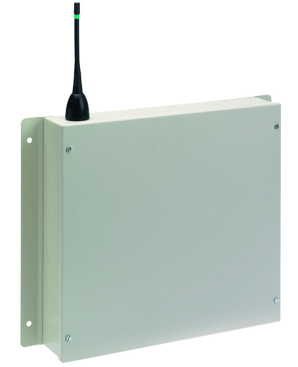
3 Introduction The connection of the UHF Remote Receiver ( ) to the SignalPoint Control Panel is detailed in the following instructions. The UHF Remote Receiver is hardwired to the Control Panel via 2 core fire resistant screened cable. The UHF remote receiver capable of receiving UHF signals from a number of transponder units on site. The transponder units are wireless devices, which receive information from detectors and then re-transmit this information to the UHF remote receiver, thus improving the overall range coverage of the system. This information is then sent to the control panel via cable. A maximum of 28 remote receivers can be connected to the Control Panel. A block diagram of a system using the UHF remote receiver is shown in Figure 1. UHF Data Transmitting Aerial VHF Data Receiving Aerial UHF Data Transmitting Aerial Fire Detection Device Transmissions (i.e. Call points/ Smoke & Heat Detectors/ Sounders). Transponder Unit UHF Remote Radio Receiver Figure 1 3
4 Tools & Test Equipment Only standard hand tools are required to install the UHF Remote Receiver. No special test equipment is needed when installing the receiver, although signals from devices can be seen if a computer with a terminal programme is connected to the system. This gives a visual indication that the remote receivers are passing device data to the main control panel. Receiver Position The maximum range between remote receiver and any device is dependant upon the environment in which the system is operating. The actual range achieved is determined by local site conditions. For range improvements high gain aerials can be attached to the remote receivers. The table below indicates relevant aerials:- UHF Remote Receiver Relevant high gain aerials High gain aerial c/w 3 metres of cable and bracket /BP /BP /BP30 High gain aerial c/w 10 metres of cable, wall mounting bracket and extension pole. High gain aerial c/w 20 metres of low loss cable, wall mounting bracket and extension pole. High gain aerial c/w 30 metres of low loss cable, wall mounting bracket and extension pole. Remote Receiver Installation The UHF remote receiver should be wired as shown in the supplied drawing PO3045. The following paragraphs outline the installation in a step by step format. Remove the four lid retaining screws situated on the front cover. The front section of the unit can now be removed. Four fixing holes are available for the unit s installation. These are clearly visible on the outside of the casing. Offer the back box up to the wall and check that the rear tamper switch operates. Should the micro switch not operate, remove the unit from the wall and carefully adjust the micro switch arm. Once the micro switch operates correctly the unit can be fixed to the wall and all external wiring connections made. The diagram PO3045 shows the wiring connections required for the remote receiver. Only those cables needed to make the remote receiver function should be routed into the case. The Remote Receiver must NOT be used as a junction box or cable termination point as this will adversely affect the performance of the system. 4
5 When all connections have been made to the remote receiver the battery can be connected, the lid can be re-fixed and mains voltage can then be applied. Software Configuration To allow the Control Panel and remote receivers to work together, some software configuration will be necessary, the following instructions detail in a step by step format how the configuration should take place for reliable communication. The menu structure indicated at the end of this section locates the menus, which require entering. 1 With the key the ON position, the screen will now display: DATE Panel In Access TIME 2 Press the 0 key. The screen will now display: 3 Press the YES key. The screen will now display: 4 Press the YES key. The screen will now display: *** Options **** > Passwords < Time and Date * PIN s and Access * >User Log On < View Users Enter your PIN For Access > Then Press YES TIME 5 Enter your PIN number (Engineering default = ) and press the YES key. The screen will now display: 6 Press any key and the screen will display: 7 Press the key, until the screen displays: 8 Press the YES button and the screen will display. 9 Press the key, until the screen displays: 10 Press the YES key and the screen will display: ************************** * Welcome Engineer * ************************** Push any Key TIME *** Options **** >Passwords < Time and Date Logging >Fire System Opts < Remote Access Yes = select Time ** Fire system ** >Dev. Disable/Test < Net. Disable/Test System Mode > Engineers Config < Printer Options ** Eng. Config ** >Device Database < Sounder Options Reset Security >Reset System < Lan Options 5
6 11 Press the key, until the screen displays: 12 Press the YES key followed by the 0 key on the keypad the screen will now display: 13 Press the key, until the screen displays: 14 Press the YES button and the screen will display: 15 Press the key, until the screen displays: 16 Press the YES button and the screen will display: ** Main Menu ** >Pins & Access < System Support System Support > Serial Comms < Pager Setup ** Serial Comms ** >Device Table < Re-start Bus Re-online Device > Bus Master Setup < Bus Remote Setup ** Master Setup** >Polling Baudrate < Auto Re-online 17 Press the key, until the screen displays: 18 Press the YES button and the screen will display: 19 Press the 1 key followed by the YES key and the screen will display: 20 Press the NO key once and the screen will display: 21 Press the key until the screen displays: 22 Press the YES button and the screen will display: 23 Once completed the screen will display: Auto Re-online > Port to use < ^^^^^^^^^^^^^ Master Port = 0 0 = Off, 1 = RS485 2 = PAGER 232 > _ YES = Finish TIME Auto Re-online > Port to use < ^^^^^^^^^^^^^ Re-online Device > Bus Master Setup < Bus Remote Setup Device Table >Re-start Bus < Re-Online Device Re-initialising Bus Please wait.* * Push any key Re-initialising Bus Please wait.*done* Push any key TIME TIME 6
7 24 Push any key and the screen will display: 25 Press the key, until the screen displays: 26 Push any key and the screen will display: Device Table >Re-start Bus < Re-Online Device Printer Redirect >Monitor Comms < Delete Device HEAP00 AUX=00 PGR=00 REM000 MAS010 T00-00 I00 L00 R00 S00 C00 Push any Key TIME The above display can be used to check how many remote receivers are communicating with the Control Panel. For each remote receiver that is connected, the MAS number shown will increase by 10. I.e. if one is connected the MAS will show MAS010 if two receivers are connected the MAS will show MAS Press the No key twice. The screen will change to display: 28 Press the key, until the screen displays: 29 Press the YES button and the screen will display: 30 Press the key, until the screen displays: 31 Press the YES button and the screen will display: 32 The collector should be set to ENABLED, press the YES key to change its status. Once set to Enabled press the NO key. The screen will display: 33 Press the NO key once and the screen will display: 34 Press the key, until the screen displays: System Support > Serial Comms < Pager Setup Logging >Remote Rxers < Ext. Comms * Remote Receivers * >Receivers Found < Enable Receiver Enable Receiver >Enable Collector < Monitor Traffic Collector: ENABLED Push Yes to change Push No to escape Enable Receiver >Enable Collector < Monitor Traffic Logging >Remote Rxers < Ext. Comms Checksum Data > Network Router < Radio Lan 7
8 35 Press the YES button and the screen will display: 36 Press the YES button and the screen will display: 37 Enter 00 followed by the YES key. The screen will display: 38 Push any key and the screen will display: 39 Press the key, until the screen displays: 40 Press the YES button and the screen will display: 41 The router should be set to ENABLED, press the YES key to change its status. Once set to Enabled press the NO key. The screen will display: * NETWORK ROUTER * >Setup local NUA < View network NUA Local NUA : Input Local NUA_ Yes= Finish Time SET AS MASTER Push Any Key Time * NETWORK ROUTER* > Setup local NUA < View network NUA Network Name > Control Routing < Send Test Routing : DISABLED Push YES to change Push NO to escape Yes/No Time Network Name > Control Routing < Send Test 42 Press the NO key twice and the screen will display: Date Panel In Access Time 43 Now turn the control keyswitch to the OFF position and the screen will display: The Remote Receiver is now programmed to the System. Date Status Normal Time 8
9 Control Panel Engineers Menu Structure **Main Menu** Pins & Access System Support Serial Comms Pager Setup Engineers Ctrl Time & Date Output Setup Logging Remote Rxers Ext.Comms Bus I/O Fire dbase Checksum Data Network Router Radio LAN *Serial Comms* Device Table Re-Start Bus Re-Online Device Bus Master Setup Bus Remote Setup Pager 232 Redir Aux 232 Redirect Printer Redirect Monitor Comms Delete Device ^^^^^^^^^^^^ *Master Setup* Polling Baudrate Auto Re-online Port to use HEAP00 AUX=00 PGR=00 REM000 MAS010 T00-00 I00 L00 R00 S00 C00 Re-Initialising Bus Please Wait.. Push Any Key Master Port =1 0=Off, 1 = RS485 2=PAGER 232 *Remote Receivers* Receivers Found Enable Receiver Enable Collector Monitor traffic ^^^^^^^^^^^^^^ Enabled Push YES to change Push NO to escape Push YES/NO TIME *Network Router* Setup local NUA View Network NUA Network Name Control Routing Send Test Local NUA : 00 Input Local NUA YES = Finish TIME Enabled Push YES to change Push NO to escape Push YES/NO TIME 9
10 Testing The System If the system is not performing as expected in terms of range, monitoring the Comms between the main and remote receivers may well indicate the cause of the problem (see Control Panel Engineers Menu Structure). For example, a large number of Time-outs by a particular remote indicates a poor connection, poor screening, or the cable passing near enough to a data cable to introduce interference onto the bus. Once UHF Remote receivers have been installed and are communicating with the Control Panel, the transponder units which will send device information to the remote receiver should be installed (see transponder installation instructions for details). 10
11 11
 -10 to +55 degrees C Up to 75% non-condensing.")
12 Controller Information TECHNICAL INFORMATION FOR THE UHF Remote Receiver Dimensions: Operating Frequencies: Operating Temperature: Humidity: Channel Spacing: Supply: Current Consumption: Battery space: Recommended battery replacement intervals: 390mm x 320mm x 80mm UHF MHz (Receiver) -10 to +55 degrees C Up to 75% non-condensing. 25 khz 230v 50Hz 154mA in standby 1 x 12volt 7Ah batteries (supplied) EMS only recommend: Yucel Model No: NP7-12 or a battery of equivalent specification 5 years 12
VHF & UHF REMOTE RECEIVERS INSTALLATION AND PROGRAMMING INSTRUCTIONS MODEL NUMBERS TMP-5414 & TMP 5428
 VHF & UHF REMOTE RECEIVERS INSTALLATION AND PROGRAMMING INSTRUCTIONS MODEL NUMBERS TMP-5414 & TMP 5428 Table of Contents Section Page No 1. INTRODUCTION... 3 2. TOOLS & TEST EQUIPMENT... 4 3. RECEIVER
Kramer Electronics, Ltd. USER MANUAL. Model: VS x 1 Sequential Video Audio Switcher
 Kramer Electronics, Ltd. USER MANUAL Model: VS-120 20 x 1 Sequential Video Audio Switcher Contents Contents 1 Introduction 1 2 Getting Started 1 2.1 Quick Start 2 3 Overview 3 4 Installing the VS-120 in
M203 LG. Multiroom Planer V2.00. Introduction. New features from software V2.00
 of M203 LG D 2.06 Attention! After updating the M203 firmware to version 2.00 or higher, we recommend completely resetting the M203 interface by pressing the Disable softkey on setup page #2 for several
Installation and User Guide 458/CTR8 8-Channel Ballast Controller Module
 Installation and User Guide 458/CTR8 8-Channel Ballast Controller Module Helvar Data is subject to change without notice. www.helvar.com i Contents Section Page Introduction 1 Installation 2 1. Attach
Re:connect M 203. RS232 Interface Revox. Dominating Entertainment. Revox of Switzerland. E 2.03
 of Re:connect M 203 RS232 Interface Revox Dominating Entertainment. Revox of Switzerland. E 2.03 Attention! After updating the firmware to version 2.00 or higher, we recommend completely resetting the
Globalmediapro SMR-650
 Globalmediapro SMR-650 16 x 16 Modularized Hybrid 3G-SDI Matrix Operation Manual CONTENTS 1. Introduction... 1 2. Applications... 1 3. Package Contents... 1 4. System Requirements... 1 5. Features... 2
of Loewe E 2.10_m1 1
 of Loewe E 2.10_m1 1 Attention! After updating the M203 firmware to version 2.00 or higher, we recommend completely resetting the M203 interface by pressing the Disable softkey on setup page #2 for several
Re:source. Communication Module. SAT Version. Dominating Entertainment. Revox of Switzerland. E2.00
 Re:source Communication Module SAT Version Dominating Entertainment. Revox of Switzerland. E2.00 Please note: Software update! Unlike the software for the Standard communication module, the SAT control
APPLICATION NOTE # Monitoring DTMF Digits Transmitted by a Phone
 APPLICATION NOTE # Product: 930A Communications Test Set 930i Communications Test Set Monitoring DTMF Digits Transmitted by a Phone Introduction This Application Note describes how to configure and connect
Intelligent Security and Fire Ltd
 User Manual Product ranges covered by this manual Vi-P14 Vi-P14A Document Reference Date Firmware Vi-Q4C1 Viq601a.doc 26/11/2009 From Viq001a21 Videoswitch Telephone 01252-851510 Ocean House, Redfields
of of Re:connect M 203 Pioneer Interface Dominating Entertainment. Revox of Switzerland. E 2.03
 of of M 203 Pioneer Interface Dominating Entertainment. Revox of Switzerland. E 2.03 Attention Software Update After updating the M203 firmware to version 2.00 or higher, we recommend completely resetting
P XGA TFT Monitor. User s Manual
 P6151 15 XGA TFT Monitor User s Manual Disclaimers This manual has been carefully checked and believed to contain accurate information. Axiomtek Co., Ltd. assumes no responsibility for any infringements
R1MS-GH3 BEFORE USE... POINTS OF CAUTION INSTRUCTION MANUAL THERMOCOUPLE & DC INPUT MODULE MODEL. (8 points; isolated)
") INSTRUCTION MANUAL THERMOCOUPLE & INPUT MODULE (8 points; isolated) MODEL BEFORE USE... Thank you for choosing M-System. Before use, please check contents of the package you received as outlined below.
INSTRUCTION MANUAL THERMOCOUPLE & INPUT MODULE (8 points; isolated) MODEL BEFORE USE... Thank you for choosing M-System. Before use, please check contents of the package you received as outlined below.
ACT 10 Digital Keypad Operating & Installation Instructions This manual is found at
 ACT 10 Digital Keypad Operating & Installation Instructions 18-00001 This manual is found at www.eaglesecuritysolutions.co.uk Installation Notes Always remember to factory default the controller before
Single cable multiswich programmer PC102W
 Single cable multiswich programmer PC102W 1. Product description The PC102W - single cable multiswich programmer (in the text - programmer) is useful instrument while configuring and troubleshooting SAT
Remote Control. degraded, causing unreliable operation. The recommended effective distance for remote operation is about 16 feet (5 meters).
.") Media Streaming Sound Bar RTS736W User Manual Remote Control using the remote control Point the remote control at the REMOTE SENSOR located on the unit (see Front Panel illustration for precise location).
Media Streaming Sound Bar RTS736W User Manual Remote Control using the remote control Point the remote control at the REMOTE SENSOR located on the unit (see Front Panel illustration for precise location).
User Manual. TCU/RCU RF Head Control Units. TCU/RCU Analogue 11/6/
 11/6/2009 www.elber.com elber@elber.it TCU/RCU RF Head Control Units User Manual Elber s.r.l.- Via Pontevecchio, 42W Phone +39-0185.35.13.33 16042 Carasco (GE) Italy Fax +39-0185.35.13.00 1 Sommario 2
B. The specified product shall be manufactured by a firm whose quality system is in compliance with the I.S./ISO 9001/EN 29001, QUALITY SYSTEM.
 VideoJet 8000 8-Channel, MPEG-2 Encoder ARCHITECTURAL AND ENGINEERING SPECIFICATION Section 282313 Closed Circuit Video Surveillance Systems PART 2 PRODUCTS 2.01 MANUFACTURER A. Bosch Security Systems
Environmental Conditions, page 2-1 Site-Specific Conditions, page 2-3 Physical Interfaces (I/O Ports), page 2-4 Internal LEDs, page 2-8
, page 2-4 Internal LEDs, page 2-8") 2 CHAPTER Revised November 24, 2010 Environmental Conditions, page 2-1 Site-Specific Conditions, page 2-3 Physical Interfaces (I/O Ports), page 2-4 Internal LEDs, page 2-8 DMP 4305G DMP 4310G DMP 4400G
2 CHAPTER Revised November 24, 2010 Environmental Conditions, page 2-1 Site-Specific Conditions, page 2-3 Physical Interfaces (I/O Ports), page 2-4 Internal LEDs, page 2-8 DMP 4305G DMP 4310G DMP 4400G
H.264 HDMI Extender over IP Extender With LED, Remote, POE, RS232 Operating Instruction
 H.264 HDMI Extender over IP Extender With LED, Remote, POE, RS232 Operating Instruction 1 Introduction This HDMI over IP Extender use the advanced H.264 as the compression type, which makes it occupy lower
EN Wireless programmable thermostat
 EN Wireless programmable thermostat Contents 1. Installation... 31 2. Description... 32 EN 3. Wireless association... 33 4. Configuration... 34 CF01 - Correcting the temperature measured... 34 CF02 - Temperature
Quad Picture Display (one big window with three small windows), press this button again to change 4 video sequence.
, press this button again to change 4 video sequence.") The HDMI Quad Multi-viewer allows you to display HDMI video signals from 4 different sources onto one HDTV. It supports Quad/POP/full screen with 6 modes and a special feature built-in auto-switching function
The HDMI Quad Multi-viewer allows you to display HDMI video signals from 4 different sources onto one HDTV. It supports Quad/POP/full screen with 6 modes and a special feature built-in auto-switching function
Kramer Electronics, Ltd. USER MANUAL. Models: VS-162AV, 16x16 Audio-Video Matrix Switcher VS-162AVRCA, 16x16 Audio-Video Matrix Switcher
 Kramer Electronics, Ltd. USER MANUAL Models: VS-162AV, 16x16 Audio-Video Matrix Switcher VS-162AVRCA, 16x16 Audio-Video Matrix Switcher Contents Contents 1 Introduction 1 2 Getting Started 1 3 Overview
CRYSTAL-800 W IRELESS IOS APP
 1. Antenna Mount 2. HDMI Input (Type D Micro) 3. Sony L-Series Battery Mount (i.e NP-F970,NP-F570) 4. LED Status Lights 5. ON / OFF Button 6. 12V DC Input 7. BIND Button (for pairing TX and RX) 8. Frequency
Be sure to run the vehicle engine while using this unit to avoid battery exhaustion.
 CAUTION: TO REDUCE THE RISK OF ELECTRIC SHOCK DO NOT REMOVE COVER (OR BACK) NO USER-SERVICEABLE PARTS INSIDE REFER SERVICING TO QUALIFIED SERVICE PERSONNE; Please Read all of these instructions regarding
SCALE & WEIGHT DISPLAYS
 The MICRO SERIES SCALE & WEIGHT DISPLAYS LARGE DIGIT MODELS Mighty-5S DPM MODELS Micro-S & Mighty-1S Mighty-1S Micro-S ELECTRO-NUMERICS, INC. Introduction The Electro-Numerics family of Digital Panel Meters
AC182A 8 Input x 8 Output S-Video Matrix Switch with Audio
 Heading AC180A 8 Input x 8 Output Composite Video Matrix Switch with Audio MARCH 2005 AC180A AC182A AC182A 8 Input x 8 Output S-Video Matrix Switch with Audio CUSTOMER SUPPORT INFORMATION Order toll-free
Instructions CCTV. ule. Even audio! Instructions - Instructions - Instructions. Send 2 Video Signals Down 1x Co-ax Cable...
 CCTV TM ule Instructions Send 2 Video Signals Down 1x Co-ax Cable......with a CCTV TM ule Even audio! Video In 2 Video In 1 1x RG59 OUT 2 Video signals down 1 co-ax. MULE2 CCTV Up to 2 videos down co-ax*
CEDAR Series. To learn more about Ogden CEDAR series signal processing platform and modular products, please visit
 CEDAR Series The CEDAR platform has been designed to address the requirements of numerous signal processing modules. Easily-installed components simplify maintenance and upgrade. To learn more about Ogden
TRUCOLOUR. 8x8 Modular Matrix INSTALLATION GUIDE
 TRUCOLOUR 8x8 Modular Matrix INSTALLATION GUIDE SAFETY PRECAUTIONS Please read all instructions before attempting to install or operate this equipment. Please keep the following in mind as you unpack and
TRUCOLOUR. 4x4 Video Matrix with HDBaseT Outputs INSTALLATION GUIDE
 TRUCOLOUR TRUCOLOUR x Video Matrix with HDBaseT Outputs INSTALLATION GUIDE SAFETY PRECAUTIONS Please read all instructions before attempting to install or operate this equipment. Please keep the following
TeamWork Kits Installation Guide
 TX 0 RX COM +5V APARATUS US TeamWork Kits Installation Guide TeamWork 400 and TeamWork 600 Kits The TeamWork 400 and TeamWork 600 kits consist of an HDMI switcher, system controller, Cable Cubby, and cables
ivw-fd122 Video Wall Controller MODEL: ivw-fd122 Video Wall Controller Supports 2 x 2 Video Wall Array User Manual Page i Rev. 1.
 MODEL: ivw-fd122 Video Wall Controller Supports 2 x 2 Video Wall Array User Manual Rev. 1.01 Page i Copyright COPYRIGHT NOTICE The information in this document is subject to change without prior notice
DATA SHEET Panorama Rudder Indicator, TRI-2
 DATA SHEET Panorama Rudder Indicator, TRI-2 Class 1 accuracy on CAN version Readable from up to 5 metres Single and dual CAN or analogue interface LED illumination DEIF A/S Frisenborgvej 33 DK-7800 Skive
HDMI 4 input 1 output Quad/Multi-viewer & Seamless Switcher. ITEM NO.: HM41E 4 x 1 HDMI Multiviewer & Seamless Switcher
 HDMI 4 input 1 output Quad/Multi-viewer & Seamless Switcher ITEM NO.: HM41E 4 x 1 HDMI Multiviewer & Seamless Switcher The HDMI Quad Multi-viewer allows you to display HDMI video signals from 4 different
MBUS 10 RS232 TO MBUS LEVEL CONVERTER
 Media and protocol converters MBUS 10 RS232 TO MBUS LEVEL CONVERTER RS232 to MBus level conversion Maximum 10 MBus slaves Baud Rate: 300 to 19200 bps RS232 MBus opto isolation Over-current and short-circuit
SY-HDBT-SLIM-100S Extender Set
 Installation Guide SY-HDBT-SLIM-100S Extender Set with HDMI, Ethernet, IR, RS232 and Power over 100m of cat6 Cable HDBaseT HDMI Extenders SY Electronics Ltd, Unit 7, Worrall Street, Salford, Greater Manchester,
SY-HDBT-100 Extender Set
 Installation Guide SY-HDBT-100 Extender Set with HDMI, IR, RS232 and Ethernet over 100m of cat6 Cable HDBaseT HDMI Extenders SY Electronics Ltd, Unit 7, Worrall Street, Salford, Greater Manchester, M5
User s Manual. 4X1 HDMI Switcher Part #: DL-HDS41
 User s Manual 4X1 HDMI Switcher Part #: DL-HDS41 Congratulations on your purchase of a DigitaLinx Switch. This manual contains information that will assist you in the installation and operation of this
Troubleshooting. 1. Symptom: Status indicator (Red LED) on SSR is constant on. 2. Symptom: Output indicator (Yellow LED) on SSR is flashing.
 on SSR is constant on. 2. Symptom: Output indicator (Yellow LED) on SSR is flashing.") Product Data Electrical Data SST (Transmitter) SSR (Receiver) Supply voltage 18 30 V dc Max. Voltage ripple 15 % (within supply range) Current consumption 100 ma (RMS) 75 ma Digital - 100 ma Max. outputs
Product Data Electrical Data SST (Transmitter) SSR (Receiver) Supply voltage 18 30 V dc Max. Voltage ripple 15 % (within supply range) Current consumption 100 ma (RMS) 75 ma Digital - 100 ma Max. outputs
Installation Guide. HDMI 4x1 Switcher
 Installation Guide HDMI 4x1 Switcher SY Electronics Ltd, Unit 7, Worrall Street, Salford, Greater Manchester, M5 4TH, United Kingdom Tel: +44 (0) 161 868 3450 Fax: +44 (0) 161 868 3459 The SY-HD-S41 is
SINGLE ZONE CLIMATE ZONING SYSTEM. Technical Manual. Polyaire Pty Ltd
 SINGLE ZONE CLIMATE ZONING SYSTEM Technical Manual Polyaire Pty Ltd 11-13 White Road GEPPS CROSS South Australia, 5094 Tel: (08) 8349 8466 Fax: (08) 8349 8446 www.polyaire.com.au CONTENTS Features 1 Application
INSTALLATION GUIDE 2.4 Inch TFT Terminal Time Attendance & Access Control
 STALLATION GUIDE.4 Inch TFT Terminal Time Attendance & Access Control Optional accessories Safety Precautions The following precautions are to keep user s safe and prevent any damage. Please read carefully
SPX-5600 Series. Operations Manual. Suprex Reader Extender - RF Wireless Interface SPX-5600MAN. Page 1 of 20
 SPX-5600 Series Operations Manual Suprex Reader Extender - RF Wireless Interface SPX-5600MAN Page 1 of 20 SPX-5600 Series: Cypress Suprex SPX-5600 Series This manual covers the operation and setup of the
Installation / Set-up of Autoread Camera System to DS1000/DS1200 Inserters
 Installation / Set-up of Autoread Camera System to DS1000/DS1200 Inserters Written By: Colin Langridge Issue: Draft Date: 03 rd July 2008 1 Date: 29 th July 2008 2 Date: 20 th August 2008 3 Date: 02 nd
Rack mounted telephone- and leased line modem for industrial applications
 Rack mounted telephone- and leased line modem for industrial applications TR-6 Rack modem for industrial PSTNand /-wire leased line applications The TR-6 is an analogue V. 9 -rack PSTN modem as well as
VGA AUDIO SWITCHER S MANUAL
 VGA AUDIO SWITCHER S MANUAL Milestone s VGA Audio Switcher is a unit whereby multiple (2/4/8/16) VGA + Audio can be switched to two (2) or multiple (simultaneous) VGA + Audio output. The switchers are
M5-H002. Multiview T-35. DVB-T to PAL / 5 channels on all TV s
 120531 M5-H002 Multiview T-35 DVB-T to PAL / 5 channels on all TV s Contents Multiview... 3 Features... 3 Caution... 3 Front & Rear Panel... 4 Connecting... 5 Programming... 6 Information... 7 Installation...8
H.264 HDMI Extender over IP Extender With LED, Remote, RS232. Operating Instruction
 SC08.6010 H.264 HDMI Extender over IP Extender With LED, Remote, RS232 Operating Instruction 1 Introduction The SC08.6010 transmitters and receivers can be used as point to point extenders up to 120m or
USER S Manual NGLT104WPD NGLT150WPD LCD TV / Monitor (IP67 Grade)
") USER S Manual NGLT104WPD NGLT150WPD LCD TV / Monitor (IP67 Grade) This Manual is revisable without further notice Contents CONTENTS ------------------------------------------------------------------- 1
USER S Manual NGLT104WPD NGLT150WPD LCD TV / Monitor (IP67 Grade) This Manual is revisable without further notice Contents CONTENTS ------------------------------------------------------------------- 1
CP-255ID Multi-Format to DVI Scaler
 CP-255ID Multi-Format to DVI Scaler Operation Manual DISCLAIMERS The information in this manual has been carefully checked and is believed to be accurate. Cypress Technology assumes no responsibility
DIGITAL SET TOP BOX STB 7017 INSTRUCTION MANUAL
 DIGITAL SET TOP BOX STB7017 INSTRUCTION MANUAL STB 7017 CHANNEL After Sales Support Now you have purchased a Tevion product you can rest assured in the knowledge that as well as your 3 year parts and labour
P-2 Installing the monitor (continued) Carry out as necessary
 Carry out as necessary") P-2 Installing the monitor (continued) Carry out as necessary Using the monitor without the bezel MDT552S satisfies the UL requirements as long as it is used with the bezel attached. When using the monitor
P-2 Installing the monitor (continued) Carry out as necessary Using the monitor without the bezel MDT552S satisfies the UL requirements as long as it is used with the bezel attached. When using the monitor
Quick Operation Guide of LTN7700/7600 Series NVR
 Quick Operation Guide of LTN7700/7600 Series NVR UD.6L0202B0042A02 Thank you for purchasing our product. If there is any question or request, please do not hesitate to contact dealer. This manual is applicable
User Manual MODEL: KK1500-TR. Touch Display LCD Monitor. Installation Guide. 15 Resistive Touch LCD Monitor
 Touch Display LCD Monitor User Manual Installation Guide 15 Resistive Touch LCD Monitor MODEL: KK1500-TR i-tech Company LLC TOLL FREE: (888) 483-2418 EMAIL: info@itechlcd.com WEB: www.itechlcd.com User
Goodmans Helpline Phone Number
 Goodmans Helpline Phone Number 0870 873 0080 contents Introduction 4 Connecting up 5 Overview diagrams 6 Getting started 8 Using the main menu 10 Troubleshooting 15 Technical Specifications 16 3 introduction
INSTALLATION & USER GUIDE
 INSTALLATION & USER GUIDE Digidim 458 8-Channel Dimmer STEP 1 Assemble Dimmer Unit STEP 2 Mount Dimmer Chassis STEP 3 Electrical Installation STEP 4 Attach Module and Make Connections STEP 5 Replace Cover
FV400 DIGITAL TV RECEIVER WITH MODULATOR INSTRUCTION MANUAL
 FV400 DIGITAL TV RECEIVER WITH MODULATOR INSTRUCTION MANUAL Please read this instruction manual carefully before using your receiver Table of Contents Introduction-----------------------------------------------------------------------------
Product model and standard
 Preface Thank you for purchasing the Ikan Blitz 400 HD Wireless Video System. This system features uncompressed high definition video with zero delay. Before using the product, please read this user s
PRODUCT NO.: PT-L735 PRODUCT NAME: Ultra Portable LCD Projector
 PRODUCT NO.: PRODUCT NAME: MAJOR FEATURES Bright - High 2600 ANSI lumens brightness Time-saving - One-touch auto setup - Automatic input signal detector - Speed start - Direct power off - Momentary switch
CH-2538TXWPKD 4K UHD HDMI/VGA over HDBaseT Wallplate Transmitter. CH-2527RX 4K UHD HDMI over HDBaseT Receiver. Operation Manual
 CH-2538TXWPKD 4K UHD HDMI/VGA over HDBaseT Wallplate Transmitter CH-2527RX 4K UHD HDMI over HDBaseT Receiver Operation Manual DISCLAIMERS The information in this manual has been carefully checked and
AVE HOME FAGOR CVBS TO DVB-T ENCODER MODULATOR. Fagor Electr6nica
 AVE HOME CVBS TO DVB-T ENCODER MODULATOR FAGOR Fagor Electr6nica TABLE OF CONTENTS 1. SPECIFICATIONS... 12 1.1 Product Overview... 12 1.2 Appearance and Description... 12 1.3 Diagram... 13 1.4 Characteristics...
Network Camera Operating Manual
 Network Camera Operating Manual Model No. WV-NW484S Before attempting to connect or operate this product, please read these instructions carefully and save this manual for future use. Preface About these
PUV-1550S-RX & TX. HDBaseT & 4K Dual HDMI Scaler Transmitter & Receiver (4K, HDCP2.2, PoH, LAN, OAR) OPERATION MANUAL
 OPERATION MANUAL") PUV-1550S-RX & TX HDBaseT & 4K Dual HDMI Scaler Transmitter & Receiver (4K, HDCP2.2, PoH, LAN, OAR) OPERATION MANUAL DISCLAIMERS The information in this manual has been carefully checked and is believed
PUV-1550S-RX & TX HDBaseT & 4K Dual HDMI Scaler Transmitter & Receiver (4K, HDCP2.2, PoH, LAN, OAR) OPERATION MANUAL DISCLAIMERS The information in this manual has been carefully checked and is believed
R5 RIC Quickstart R5 RIC. R5 RIC Quickstart. Saab TransponderTech AB. Appendices. Project designation. Document title. Page 1 (25)
") Appendices 1 (25) Project designation R5 RIC Document title CONTENTS 2 (25) 1 References... 4 2 Dimensions... 5 3 Connectors... 6 3.1 Power input... 6 3.2 Video I... 6 3.3 Video Q... 6 3.4 Sync... 6 3.5
Appendices 1 (25) Project designation R5 RIC Document title CONTENTS 2 (25) 1 References... 4 2 Dimensions... 5 3 Connectors... 6 3.1 Power input... 6 3.2 Video I... 6 3.3 Video Q... 6 3.4 Sync... 6 3.5
Model Extend HDMI audio and video connections up to 300 feet. Add up to 8 additional receivers with a dedicated network switch
 HDMI Extender over Single CAT 6 Cable with IR Control Model 103002 Extend HDMI audio and video connections up to 300 feet Utilize existing Cat 6 wiring for an easy installation Add up to 8 additional receivers
Copyright 2013 ACURA Global. UHF860 RFID READER. User s manual. English draft TM970180
 Copyright 03 ACURA Global. UHF860 RFID READER User s manual English draft TM97080 April 0, 03 Copyright 03: without a written approval from ACURA Global Inc, this document is not allowed to be duplicated
SAT IF distribution system
 7. Technical specifications Type cs43 RF input frequency range pr. 50-350 MHz inputs number 4 level pr. 55...88 dbµv 60...93 dbµv symbol rate 3 45 Ms/s return loss/impedance > 0 db/75 Ω LNB powering/control
-TECH DIGITAL. Explore The High DefinitionWorld. Website: Hot Line: [US] USER MANUAL
![-TECH DIGITAL. Explore The High DefinitionWorld. Website: Hot Line: [US] USER MANUAL](/thumbs/80/80689593.jpg "-TECH DIGITAL. Explore The High DefinitionWorld. Website: Hot Line: [US] USER MANUAL") -TECH DIGITAL Explore The High DefinitionWorld Website: www.jtechdigital.com Hot Line: 1-888-610-2818[US] USER MANUAL J-Tech Digital ProAV H.264 Encoder/Decoder Many to Many HDMI Extender RoHS 1 Operating
-TECH DIGITAL Explore The High DefinitionWorld Website: www.jtechdigital.com Hot Line: 1-888-610-2818[US] USER MANUAL J-Tech Digital ProAV H.264 Encoder/Decoder Many to Many HDMI Extender RoHS 1 Operating
INSTRUCTION MANUAL. 19 HD Widescreen Water Resistant Television VSPA19LCD-AE1B VSPA19LCD-AE1M VSPA19LCD-AE1W. Model No. FINGER TOUCH TECHNOLOGY RATED
 INSTRUCTION MANUAL 19 HD Widescreen Water Resistant Television VSPA19LCD-AE1B Model No. VSPA19LCD-AE1M VSPA19LCD-AE1W FINGER TOUCH TECHNOLOGY IMPORTANT: Please read these instructions before installing
INSTALLATION MANUAL FT-FOTR-1VDE-ST-S
 INSTALLATION MANUAL FT-FOTR-1VDE-ST-S 1-Channel Digital Duplex Baseband Video Transmitter and Receiver With Reverse Data Transmission & Ethernet Transmission v1.0 4/5/11 1 PACKAGE CONTENTS This package
2-Port HDMI Automatic Video Switch - 4K with Fast Switching
 2-Port HDMI Automatic Video Switch - 4K with Fast Switching Product ID: VS221HD4KA Create a powerful visual experience, with the ability to switch between two 4K video sources seamlessly. This 2-port HDMI
Radio Thermostat Clock
 Radio Thermostat Clock Installation & User Instructions Part number: ZU0800009 80.10.1375.7_feeling_ks_fer_en.indd 1 18.04.2013 11:25:42 Table of contents Safety instructions... 3 Product details... 4
AES-402 Automatic Digital Audio Switcher/DA/Digital to Analog Converter
 Broadcast Devices, Inc. AES-402 Automatic Digital Audio Switcher/DA/Digital to Analog Converter Technical Reference Manual Broadcast Devices, Inc. Tel. (914) 737-5032 Fax. (914) 736-6916 World Wide Web:
SYMBOLS USED ON THE RECEIVER... 3 SAFETY INSTRUCTIONS... 4 I.GENERAL INFORMATION...
 Table of Contents SYMBOLS USED ON THE RECEIVER... 3 SAFETY INSTRUCTIONS... 4 I.GENERAL INFORMATION... 5 1. Preface... 5 2. Main Features... 5 3. General Operation of the Receiver... 6 4. Front Panel...
Single & Dual Input HD Digital DVB-T Modulators
 Radio Frequency Range Installation Diagram digi-mod HD-1000DM / HD-2000DM www.resi-linx.com Single & Dual Input HD Digital DVB-T Modulators ANT IN 1 2 3 4 AUX MOD RF IN TV OUTPUTS MOD RF IN (PWR/IR PASS)
Features: Model : ATZ HDBT-E70-RB Description : HDBaseT Extender Receiver Box for HMDI w/ir+pol (70m)
") The ATZ HDBT-E70-RB is part of ATZ s expanding Multi Video HDBaseT Cat Extender. Single side connections for HDMI, Control, and Power provide a cleaner wiring and rack mounting solution. The design allows
The ATZ HDBT-E70-RB is part of ATZ s expanding Multi Video HDBaseT Cat Extender. Single side connections for HDMI, Control, and Power provide a cleaner wiring and rack mounting solution. The design allows
SCART COMMANDER. Channels 2 audio channels 4 video channels 2 digital channels 2 control channels (pin 8 & 16)
") SCART COMMANDER PRODUCT OVERVIEW The Keene Scart Switch Box is a high quality audio/video switcher designed to allow the connection of multiple sources to one display. Particular attention has been given
SCART COMMANDER PRODUCT OVERVIEW The Keene Scart Switch Box is a high quality audio/video switcher designed to allow the connection of multiple sources to one display. Particular attention has been given
G ARD SECURITY SYSTEM Product Listing 2007
 G ARD SECURITY SYSTEM Product Listing 2007 G ARD L2000 WIRELESS ALARM SYSTEM Totally Wireless Wireless Telephone G'ARD L-2000 Wireless Alarm System uses the state of art microprocessor for data processing.
AES-404 Digital Audio Switcher/DA/Digital to Analog Converter
 Broadcast Devices, Inc. AES-404 Digital Audio Switcher/DA/Digital to Analog Converter Technical Reference Manual Broadcast Devices, Inc. Tel. (914) 737-5032 Fax. (914) 736-6916 World Wide Web: www.broadcast-devices.com
BRIGHTLINK HDMI EXTENDER OVER ETHERNET - H METER MODEL: BL-EXT-IP-264
 BRIGHTLINK HDMI EXTENDER OVER ETHERNET - H.264-120 METER MODEL: BL-EXT-IP-264 Operating Instructions BRIGHTLINKAV.COM 1 Introduction This HDMI over IP Extender use the advanced H.264 as the compression
F M1SDI 1 Ch Tx & Rx. HD SDI Fiber Optic Link with RS 485. User Manual
 User Manual F M1SDI 1 Ch Tx & Rx HD SDI Fiber Optic Link with RS 485 User Manual 1Introduction 1.1Overview 1.2Features 1.3Application 2 Panel 2.1 Front Panel 2.2 Rear Panel 3Technical Specification Contents
ALM-6813/6812 INSTALLATION AND PROGRAMMING MANUAL
 ALM-6813/6812 INSTALLATION AND PROGRAMMING MANUAL Installation and programming Manual v2.2 1 MARSS Solar Defender SYSTEM This guidebook provides the essential instructions to install and configure the
USER & ENGINEER INSTRUCTION MANUAL
 USER & ENGINEER INSTRUCTION MANUAL BENSON CP4 USER INSTRUCTIONS CONTENTS PAGE SUBJECT PAGE No. Contents Page... 1 CP4 Basic Setting Guide... 2-3 Standard Terms... 4 Normal RUN Mode... 4 Override... 5
Multiroom Solution Guide HDR-3000T + H3
 Multiroom Solution Guide HDR-3000T + H3 Contents What s in the box?... 3 How multiroom solution works... 4 How to connect H3 and HDR-3000T... 5 How to pair H3 and HDR-3000T... 7 What you can do with multiroom
Kramer Electronics, Ltd. USER MANUAL. Model: 900xl. Power Amplifier
 Kramer Electronics, Ltd. USER MANUAL Model: 900xl Power Amplifier Introduction Contents 1 Introduction 1 2 Getting Started 1 2.1 Recycling Kramer Products 1 3 Overview 2 4 Your 900xl Power Amplifier 3
TABLE OF CONTENTS 1. OVERVIEW INSTALLATION VIDEO CONNECTIONS GENERAL PURPOSE INPUTS & OUTPUTS SPECIFICATIONS...
 TABLE OF CONTENTS 1. OVERVIEW...1 2. INSTALLATION...3 2.1. VIDEO CONNECTIONS... 3 2.2. GENERAL PURPOSE INPUTS & OUTPUTS... 4 3. SPECIFICATIONS...6 3.1. SERIAL DIGITAL VIDEO INPUTS... 6 3.2. SERIAL DIGITAL
and HDCP 2.2 supported Digital Matrix Switcher FDX-32UHD Specification
 RoHS 4K@60 and HDCP 2.2 supported Digital Matrix Switcher Specification The IDK is a new level of Digital Matrix Switcher for AV systems which supports resolution up to 4K @60 and HDCP2.2. The can input
T3316 IP QAM Modulator User Manual
 T3316 IP QAM Modulator User Manual SW Version: 1.02 HW version: 0.70.0.0 Web NMS version: 1.02 Intended Audience About This Manual This user manual has been written to help people who have to use, to integrate
Video Server SED-2100R/S. Quick Installation Guide
 Video Server SED-2100R/S Quick Installation Guide Feb.10,2006 1 1 Getting Started 1.1 PACKAGE CONTENTS SED-2100 Warranty Card Software CD Hook up & Screws Terminal Blocks for Power & DI/O Power Adaptor
TeamWork 601 Kit Installation Guide
 C G G TX RX COM +V APARATUS US 0 TeamWork 0 Kit Installation Guide TeamWork 0 Kit The TeamWork 0 kit consists of an analog and digital video switcher, system controller, Cable Cubby, and cables packaged
Blu-ray Disc /DVD Home Theatre System BDV-E6100 BDV-E4100 BDV-E3100 BDV-E2100. Start here. Quick start guide BDV-E6100 BDV-E4100 BDV-E3100 BDV-E2100
 Blu-ray Disc /DVD Home Theatre System BDV-E6100 BDV-E4100 BDV-E3100 BDV-E2100 GB Start here Quick start guide BDV-E6100 BDV-E4100 BDV-E3100 BDV-E2100 1 What s in the box/setting up the speakers BDV-E6100
ATS50SAW Programmable Selective Amplifier
 ATS50SAW Programmable Selective Amplifier Technical Specifications N Input BI/BII (40 108 MHz) 1 N Input BIII/DAB (170 320 MHz) 1 N AUX input (40 860 MHz) 1 N Programmable Input UHF (470 790 MHz) 4 N IF-SAT
DXI SAC Software: Configuring a CCTV Switcher. Table of Contents
 APPLICATION NOTE MicroComm DXI DXI SAC Software: Configuring a CCTV Switcher Table of Contents 1. Intent & Scope... 2 2. Introduction... 2 3. Options and Parameters... 2 3.1 When to switch the CCTV...2
SIMATRIX NEO V2 Modular Video Matrix
 SIMATRIX NEO V2 Modular Video Matrix SIMNEO-168 V2 Modular design Expandable up to 224 video inputs, 32 video outputs Up to 8 keyboards can be connected for control Multiple protocol driver for the direct
JAMAR TRAX RD Detector Package Power Requirements Installation Setting Up The Unit
 JAMAR TRAX RD The TRAX RD is an automatic traffic recorder designed and built by JAMAR Technologies, Inc. Since the unit is a Raw Data unit, it records a time stamp of every sensor hit that occurs during
1 Unpack. Taking the TV Out of the Box. Included in this Box. Stand Parts and Cables. Remote Control. Also included
 1 Unpack Taking the TV Out of the Box Warning: Do not touch the TV s screen when you take it out of the box. Hold it by its edges only. If you touch the screen, you can cause the TV panel to crack. Included
FlexiScan. Impro FlexiScan 4-Channel Controller INSTALLATION MANUAL
 MODEL NUMBER: HCM991-0-0-GB-XX FlexiScan SPECIFICATIONS Impro FlexiScan 4-Channel Controller INSTALLATION MANUAL Working Environment... Security... Input Voltage... The Impro FlexiScan is designed to work
ZN-PD. Smallest Air Particle Sensor in the Industry for In-line Measurement. Air Particle Sensor. Features
 Air Particle Sensor Smallest Air Particle Sensor in the Industry for In-line Measurement Suitable for continuous measurement. With Realtime Clean Air Monitor. Be sure to read Safety Precautions on page
The 6700 series Panel lock and destination protect
 Table of Contents 1 Introduction 4 2 Panel types 5 The 6700 series Panel lock and destination protect 3 Installation 10 Connector I/O Installing the power supply Earthing the panel Inserting and removing