Support Frame STB Assembly and Operating Instructions
|
|
|
- Evelyn Clifton Ray
- 5 years ago
- Views:
Transcription


1 Support Frame STB Assembly and Operating Instructions
 if only one side of the formwork can be erected. Usually, it is not practical to tie through the forms.")
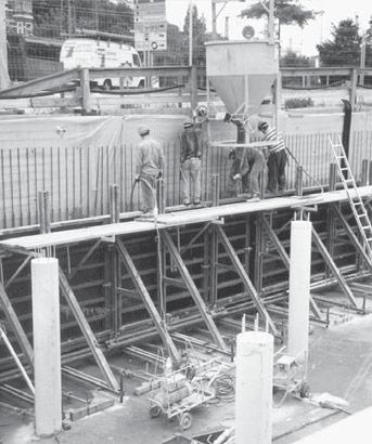
2 Fig. 2.1 Support frame STB 450 Fig. 2.2 Support frame STB 300 Fig. 2.3 Brace bracket SK 150 Product features The support frames are mainly used for pouring against existing structures (walls, rock, soil, sheet piling, foundations etc.) if only one side of the formwork can be erected. Usually, it is not practical to tie through the forms. Therefore, the total concrete pressure has to be transferred from the formwork via a support structure into the foundation. The MEVA support frames are painted steel structures. See the Load Charts (separate book) for details about concrete pressure and anchor loads in standard applications. Safe working loads according to DIN Attention Check on site to make sure that the occurring tensile forces Z and the pressures V can be safely transferred into the foundation or floor slab. Especially the concrete strength and the kind of rebar used need to be reviewed. If the support frames are used on top of slabs make sure to support the slab where the vertical forces occur in order to transfer these into the foundation. Abbreviations, measurements, figures and tables The abbreviation STB is used for the support frames. The abbreviation ST is used for the StarTec formwork and the abbreviation M for the Mammut formwork. Anchor system Threadbar DW 15 Threadbar DW 20 Threadbar DW 26.5 Safe working load 90 kn 160 kn 250 kn DIN means Deutsche Industrie-Norm (German Industrial Standard). E DIN (E = Entwurf / draft) means that the DIN is in draft status and not yet approved of. Any further abbreviations are explained where they are used the first time. When using the support frames the following points need to be looked at with special care: Foundations and floor slabs etc. must be able to resist the transmitted loads (a static calculation might be required). The "opposite side" of the single-sided formwork, i.e. the existing structure must be able to resist the concrete pressure as well. Anchors must be able to resist the transferred loads. Anchors must not be welded, heated or deformed. In case of more complicated or special cases not dealt with in these instructions, please contact the MEVA experts for advice. Deviations from these instructions always require engineering calculations and a separate static proof. Measurements: These instructions use the metric system and thus m (for metre), cm (for centimetre) and mm (for millimetre). Dimensions without a measure are in cm. The page numbers in these instructions start with the product abbreviation STB. The figures and tables are numbered per page. Depending on its product abbreviation, a cross reference in the text refers to a page, table or figure in these instructions or in other instructions. Updated 3 December 2008 STB-2


3 Support Frame STB Please note Contents These Assembly and Operating Instructions contain information, instructions and hints describing how to use the MEVA equipment on the construction site in a proper, quick and economic way. Most examples shown are standard applications that will occur in practice most often. For more complicated or special applications not covered in these instructions, please contact the MEVA experts for advice. When using our products the federal, state and local codes and regulations must be observed. Many of the details shown do not illustrate the wall formwork system in the ready-to-pour condition as to the aforementioned safety regulations. Please adhere to these technical instructions when applying the equipment described here. Deviations require engineering calculations and analysis to guarantee safety. Please observe the assembly instructions that your local contractor or employer has created for the site on which the MEVA equipment is used. Such instructions are intended to minimise site-specific risks and must contain the following details: The order in which all working steps including assembly and disassembly must be carried out The weight of the panels and other system parts The type and number of ties and braces as well as the distance between them The location, number and dimensions of working scaffolds including working area and protection against falling down Pick points for panel transport by crane. With regard to panel tranport, please observe these Assembly and Operating Instructions. Any deviation will require a static proof. Important: Generally, only well maintained material may be used. Damaged parts must be replaced. Apply only original MEVA spare parts for replacement. Attention: Never wax or oil assembly locks. Support frame STB Support frame STB Preassembly of STB units...6 Diagonal bracing...7 Working platforms...8 Anchoring...9 Anchoring details for STB Anchoring details for STB Anchoring auxiliary...12 Anchoring (step by step)...13 Stop ends...14 Corner bracket STB and support frame STB Corner bracket STB and support frame STB Crane ganging...18 Moving STB units with trolley...19 Brace bracket SK Transport: Stacking...22 Transport: Loading of trucks...23 Service...24 Product List...27 Load Charts...43 STB STB-3

 or it can be screwed to the multi-function profiles of the panels with flange screws 18. Unit Fig. 4.")
.")
 and Mammut (Fig. 4.8) formwork systems. Support frame STB 300... 29-402-62 Fixing screw 35/DW15.")
4 Support frame STB 300 For static and economical reasons we recommend using the STB in combination with panels in horizontal position. Pouring height The support frame STB 300 can be used for a pouring height up to 3.30 m. Horizontal panels The STB 300 can be attached to the formwork at the tie holes with fixing screws 35 and flange nuts 100 (Fig. 4.4 and 4.5) or it can be screwed to the multi-function profiles of the panels with flange screws 18. Unit Fig. 4.2 StarTec formwork Unit Fig. 4.3 Mammut formwork Fig. 4.1 Support frame STB 300 with panels in horizontal position Attention Before mounting the STB to the formwork panel, set spindle at middle position. Vertical panels The STB 300 can be used together with the cross beam 300 (Fig. 4.6). Placed horizontally between the formwork panel and support frame, the cross beam 300 allows the building of units while the distance between the support frames is arbitrary. The cross beam 300 is designed to match the StarTec (Fig. 4.7) and Mammut (Fig. 4.8) formwork systems. Support frame STB Fixing screw 35/DW Articulated flange nut 15/ Cross beam Flange screw Flange screw Fig. 4.4 Detail Fixing screw at the side of the STB Fig. 4.6 Support frame STB 300 with panels in vertical position Fig. 4.5 Detail Fixing screw at the side of the facing Unit Fig. 4.7 StarTec formwork Unit Fig. 4.8 Mammut formwork STB-4
.")
 11.")

5 Support Frame STB Support frame STB 450 Fig. 5.1 Up to a formwork height of 5.00 m: 3 flange screws per STB are recommended Fig. 5.2 Up to a formwork height of 6.50 m: 4 flange screws per STB are recommended Possible Use The STB 450 is designed for single-sided formwork up to 5.00 m (Fig. 5.1). By using height extensions 150 and other equipment, formwork can be erected at the following heights: 6.50 m 1 height extension (Fig. 5.2) 8.00 m 2 height extensions, base extensions, Triplex SB braces 9.50 m 3 height extensions, base extensions, Triplex SB braces (Fig. 5.3) m 4 height extensions, base extensions, Triplex SB braces (Fig. 5.4) m 4 height extensions, base extensions, Triplex SB braces Depending on the site and feasible Triplex bracing, support frame constructions for formwork of m or higher can be built. STB Attachment The STB 450 can be attached to the formwork at the tie holes with fixing screws 35 and flange nuts 100 or it can be screwed to the multi-function profiles of the panels with flange screws 18. Fig. 5.3 Up to a formwork height of 9.50 m: 6 flange screws per STB are recommended Fig. 5.4 Up to a formwork height of m: 7 flange screws per STB are recommended Support frame Height extension Base extension Fixing screw 35/DW Articulated flange nut 15/ Flange screw STB-5
.")


6 Preassembly of STB units Assembly area The area where the formwork and STB units ares pre-assembled should be clean, even and capable of taking the expected weight. The support frames are attached at the backside of the formwork panels (Fig. 6.1). Assembly The support frame can be attached to the formwork at the tie holes with fixing screws 35 and flange nuts 100 or it can be screwed to the multi-function profiles of the panels with flange screws 18. The pre-assembled units should rest on square timbers (face down) on the ground before they are flown into place. Fig. 6.1 Assembly of the heavy duty braces Triplex Depending on the overall height, it may be required to attach Triplex braces to the height and base extensions. All the accessories for the connection (nuts, bolts and pins) come with the height and base extenstions (Fig. 6.2 through 6.4). Fig. 6.3 Observe the Triplex assembly and operating instructions. Fig. 6.2 Fig. 6.4 STB-6


7 Support Frame STB Diagonal bracing Scaffold tubes with Ø 48.3 x 4.05 mm, bolton couplers 48/M14 and swivel-joint couplers 48/48 are necessary to build the required diagonal bracing. Units built out of STB 300 frames only need 1 horizontal tube (Fig. 7.1) Units built out of STB 450 frames need 2 horizontal and 1 diagonal scaffold tube (Fig. 7.2). Fig. 7.1 Fig. 7.2 If height extensions are used, one additional horizontal scaffold tube per height extension is required from the second height extension on (Fig. 7.3 and 7.4). STB Fig. 7.3 Fig. 7.4 Scaffold tube 48/ / / Swivel-joint coupler 48/ Bolt-on coupler 48/M STB-7


8 Working platforms IThe scaffolding brackets 90 and 125 together with guard-railing posts can be used to build a working platform. The procedure is as with a two-sided wall formwork. For details see the Assembly and Operating Instructions of the formwork you are using. For a safe access to the platform we recommend using the MEVA Stair Tower. Admissible load 150 kg/m², scaffold group 2 according to DIN 4420, part 1. Max. influence width 2.00 m, planking with classification SH 10. Fig. 8.1 STB 300 and Mammut formwork Fig. 8.2 STB 300 and StarTec formwork Attachment of boards at scaffolding bracket with bolts 10 mm and a minimum length of 110 mm STB 450 When using the STB 450 support frame we recommend bolting planks or boards to the support frame or height extension (Fig 8.3 and 8.4). The holes for the attachment of height extensions can be used. The STB 450 and height extensions 150 provide pockets for sliding in the guard-railing posts. Platform layout Since the STB units can be built in a flexible way and combined with different formwork systems with different heights, check and determine in the planning stage what platform layout will be used. Make sure to observe the maximum permissible fall height. Scaffolding bracket Guard-railing post Guard-railing post Side railing 90/ Side railing 125/ Fig. 8.3 STB 450 and Mammut formwork Fig. 8.4 STB 450 and StarTec formwork Attachment of boards at scaffolding bracket or extensions with bolts 10 mm and a minimum length of 110 mm STB-8

.")

9 Support Frame STB Anchoring Fig. 9.1 Fig. 9.2 Depending on the load, there are different ways to anchor the support frames: Anchor loop 15 (20) in combination with the cross stiffener 44 (Fig. 9.1 and 9.2). Anchor loop in turned configuration if support frame sits on top of a slab, see fig. 9.2 for an example. It needs to be discussed with the stress analyst if an additional rebar is required. Anchoring by using a 20 or 26.5 mm threadbar and twin channel 80 or 245 (Fig. 9.4). STB Fig. 9.3 Anchor loop Fig. 9.4 Cross stiffener Twin channel 245/ Twin channel 80/ Twin channel 80/ STB-9


.")

10 Anchoring details for STB 300 Figures 10.1 and 10.2 show an STB 300 with panels in horizontal position Fig Fig Figures 10.3 and 10.4 show an STB 300 with panels in vertical position, e.g. for corner solutions. When using the STB we recommend anchor loop 15. If the corner bracket is used, we recommend using single threadbars in the corner area. Anchor loop Anchor loop Coupling nut 15 (SW 30) (SW 36) Tie rod DW 15/ Tie rod DW 20/ Flange nut Articulated flange nut 15/ / Anchoring auxiliary 15 STB M alignment rail Fig Fig STB-10


.")

11 Support Frame STB Anchoring details for STB 450 Figures 11.1 and 11.2 show an STB 450 with panels in horizontal position Fig Fig Figures 11.3 and 11.4 show an STB 450 with panels in vertical position, e.g. for corner solutions. For the amount and type of required threadbars (DW 15, DW 20 or DW 26.5) see the Load Charts (separate manual). STB Anchoring auxiliary 20 STB STB Fig Fig Hexagonal nut 20 (SW 36) (SW 46) Counter plate 120x120x20/ x120x20/ Tie rod DW 26.5/ Coupling nut Twin channel 245/ / / STB-11


12 Anchoring auxiliary The anchoring auxiliary STB facilitates the installing of threadbars into the foundation. The auxiliaries are attached to the rebar and guarantee an angle of 45. The threadbar can be slid through the auxiliary at any position, which allows adapting to any foundation size. The plastic sleeve (DW 15 without thread, DW 20 and DW 26.5 with thread) keeps the threadbar at the ideal position. Packing units Anchoring auxiliary 15 STB: One unit contains 50 pieces. Anchoring auxiliary 20 and 26.5 STB: One unit contains 40 pieces. Fig Coupling nut Anchoring auxiliary Plastic sleeve Threadbar The plastic sleeves are included in the delivery and on site only need to be pressed into the hole of the anchoring auxiliary. Fig Wall formwork Twin channel 245 Threadbar Support frame STB 450 Coupling nut Anchoring auxiliary 15 STB STB STB Fig Anchoring auxiliary Threadbar Counterplate Hexagonal nut STB-12


13 Support Frame STB Anchoring (step by step) Fig Fig Anchor loop DW 15/DW Install the anchor loop by using the anchoring auxiliary 15 STB or 20 STB which can be attached to the rebar (Fig and 13.2). Observe the required concrete cover! 2. Screw the coupling nut on the threadbar (Fig. 13.3) and then both onto the anchor loop (Fig. 13.4). Fig Fig Threadbars DW 20 and DW Attach the counter plate 120 and the hexagonal nut to the threadbar. 2. Install the threadbars by using the anchoring auxiliary 20 STB or 26.5 STB which can be attached to the rebar. The threadbar must be completely screwed into the hexagonal nut (Fig and 13.6). Observe the required concrete cover! 3. Screw the coupling nut onto the (extension) threadbar (Fig. 13.7) and then both on the (cast in) threadbar (Fig. 13.8). STB Fig Fig Fig Fig STB-13


14 Stop ends The stop end bracket SB 110 can be used for walls up to 110 cm thick. It has a sliding part that at the stop end is slid until the existing wall etc. (Fig ). The stop end bracket is mounted by sliding it horizontally between the support frames and by attaching a threadbar DW 15/45 and a flange nut 100 or an articulated flange nut 15/120 to the nuts of the multi-function profiles of the panels (StarTec, Mammut or Mammut 350). This way the support frame is located between the formwork panel and the stop end bracket. When mounting the stop end bracket, please observe the following cases: Mammut formwork: When attaching the stop end bracket at a horizontal panel, make sure the panel is turned in a way that its bottom is directed to the side where the sliding part of the stop end bracked is required to form the stop end (Fig und 14.2). Mammut and StarTec: The clamping device for the stop end bracket SB 110 must be used for the attachment of the stop end bracket (Fig through 14.4). Sliding part Fig Mammut panel for horizontal use; the bottom of the panel must be directed to where the sliding part of the stop end bracket is required Stop end bracket Sliding part bottom Fig Mammut panel for horizontal use Fig StarTec panel for horizontal use Clamping device for stop end bracket through support frame M panel 250 (horizontal) Flange nut ST panel 270 (horizontal) Flange nut top Threadbar in multifunction profile Support frame STB 450 Clamping device for stop end bracket through support frame Threadbar in multifunction profile Stop end bracket SB Clamping device for stop end bracket SB Flange nut Articulated flange nut 15/ Tie rod DW 15/ Stop end bracket Fig StarTec panel for horizontal use Support frame STB 450 STB-14


15 Support Frame STB Stop ends Figures 15.1 through 15.4 show formwork and support frames with different heights and the required number of stop end brackets. Please note that an STB 450 with 3 height extensions 150 requires 6 stop end brackets while an STB 450 with 4 height extensions requires 7 stop end brackts. Fig An STB 300 requires 2 stop end brackets Fig An STB 450 requires 3 stop end brackets STB Fig An STB 450 with 1 height extension 150 requires 4 stop end brackets Fig An STB 450 with 2 height extensions 150 requires 5 stop end brackets STB-15


16 Corner bracket STB and support frame STB 300 Single-sided corner areas can be formed by using the corner bracket STB which must be attached to the multi-function profiles by using flange screws 18. Each corner requires 2 support frames. For detailed dimensions of anchor positions see fig and For the anchoring of STB brackets also see pages STB-9 through STB-13. Fig StarTec formwork Make sure to use panels in vertical position (Fig. 16.3). To support the joint between the "corner" panel and the adjacent panel use horizontal steel rails and set back the anchors for the support frame by 10 cm. A maximum formwork height of 3.30 m is possible when using StarTec and STB M alignment rail 44 Mammut formwork You should use a "corner" panel in vertical position and continue to use the large size gangs as usual. Horizontal steel rails are not required. A maximum formwork height of 3.30 m is possible when using the STB 300. Fig Max. 250 cm Attention The dimensions for the anchor positions must be observed. Corner bracket STB Flange screw M alignment rail Twin channel 80/ Fig STB-16


17 Support Frame STB Corner bracket STB and support frame STB Fig Single-sided corner areas can be formed by using the corner bracket STB which must be attached to the multi-function profiles by using flange screws 18. Each corner requires 2 support frames. For detailed dimensions of anchor positions see fig and For the anchor ing of STB brackets see also pages STB-9 through STB Twin channel 80/22 StarTec formwork Make sure to use panels in vertical position. To support the joint between the "corner" panel and the adjacent panel use horizontal steel rails and set back the anchors for the support frame by 10 cm. Fig Mammut formwork You should use a "corner" panel in vertical position and continue to use the large size gangs as usual. Steel rails are not required. STB Max. 250 cm Attention The dimensions for the anchor positions must be observed. Make sure that the inside corner and "corner" panel are absolutely flush when installing them. Fig Corner bracket STB Flange screw Twin channel 80/ STB-17


. Fig. 18.")

18 Crane ganging For crane ganging, each panel must be attached to the support frame STB 300 or STB 450. STB 300 units STB 300 units with a maximum width of 3.50 m are moved by using the crane hook of the wall formwork system which is used (Fig and 18.2). Make sure to always use 2 crane hooks and watch their capacity. STB 450 units The STB 450 and extension 150 are equipped with crane eyes. When flying STB 450 units with extensions, crane slings should be used and be attached at the crane eyes of the top extension (Fig and 18.4). Fig Mammut and STB 300 Fig StarTec and STB 300 Attention Do not strip STB units by breaking them free from the concrete by crane! When setting STB units down to the ground make sure they do not tilt over. If necessary use a counter weight. Fig Mammut and STB 450 Fig Mammut 350 and STB 450 STB-18


19 Support Frame STB Moving STB units with trolley STB units can easily and quickly be moved around on the job with the trolley waler if a crane cannot be used, e.g. in tunnels. The trolley waler can be mounted to the STB 300 and STB 450. Attention The support frames must not stand on trolley spindles while pouring. When using the STB 300 make sure to remove the trolley waler adjacent to the panels; otherwise anchoring is not possible. Observe the trolley waler instructions. Fig STB 300 with trolley waler Fig STB 300 with trolley waler Assembly of the trolley waler The trolley waler is bolted to the support frames (counter plates and nuts are already attached to the waler). When moving the unit, a counter weight is necessary to avoid tilting over (the weight depends on the formwork height and support frame). One unit requires 2 trolley walers, 4 wheel adapters and 4 trolley spindles 48/70. Depending on the weight, 4 swivel type castors of 2 or 6 or 10 tons are required. The wheels are mounted to the waler by raising the unit with the spindle. STB Fig STB 450 with trolley waler Fig STB 450 with trolley waler Trolley waler Trolly waler Wheel adapter Spindle 48/ Swivel type castor 2 t t t STB-19
. See also p. STB-21.")

20 Brace bracket SK 150 The brace bracket SK 150 is used to form stop ends of slabs or foundations, even on sloped surfaces (Fig and 20.2). See also p. STB-21. Brace bracket SK 150 Adjustment range SRL 120 = SRL 170 = Brace SRL 120 Fig Brace bracket SK 150 Brace SRL 170 Brace bracket SK Brace SRL Brace SRL Fig STB-20
 Positioning support SK Wood spacer, depending on width of joint Typical application: Foundation slab with joint tape The positioning support SK allows for an exact")
 The braces SRL 120 or 170 and the positioning support SK must be ordered separately. Inner joint tape (waterstop) Base seal Fig. 21.")
21 Support Frame STB Brace bracket SK 150 Joint seal Insulation alkus facing Support for power screed Brace bracket SK 150, max. distance = 140 cm (max. fresh concrete pressure 20 kn/m²) Positioning support SK Wood spacer, depending on width of joint Typical application: Foundation slab with joint tape The positioning support SK allows for an exact levelling and positioning of the stop end, even on sloped surfaces. The brace bracket can easily be attached to the Dywidag threaded nuts of formwork panels. 150 Concr. pressure max. 20 kn/m² Mammut 250/75 Brace SRL 120 (170) The braces SRL 120 or 170 and the positioning support SK must be ordered separately. Inner joint tape (waterstop) Base seal Fig Fi scher anchors FHA 18 or similar STB Positioning support SK Flange screw Flange screw STB-21


. Fig. 22.1 Support frame STB 450 4 support frames can be stacked.")

22 Transport: Stacking Brace bracket SK 150 To transport brace brackets, use MEVA stacking racks. One rack takes 25 brackets, folded without braces (Fig. 22.1). Suppport frame STB support frames can be stacked. To facilitate stacking, the frames are equipped with a welded-on stacking device (Fig and 22.3). Fig Support frame STB support frames can be stacked. To facilitate stacking, the frames are equipped with a welded-on stacking device (Fig und 22.5). Fig Fig Stacking device Stacking rack Fig Fig Stacking device STB-22
23 Support Frame STB Transport: Loading of trucks Make sure that all material is secured properly. Suppport frame STB x 10 = 60 frames (Fig and 23.2) Fig Suppport frame STB x 4 = 12 frames (Fig and 23.4) Fig Max. transport length: m (Europe) Max. transport width: 2.50 m (Europe) Safety regulations When using or transporting our products, the federal, state, and local codes and regulations must be observed. STB Fig Fig Max. transport length: m (Europe) Max. transport width: 2.50 m (Europe) STB-23


24 Service Support frame cleaning The parts of the support frame STB are cleaned professionally upon return. Cleaning and regeneration of wall formwork Cleaning is done using industrial equipment with assembly lines. The regeneration is carried out as follows: The frames are checked and, if necessary, repaired, painted and provided with a new facing. As long as the formwork equipment is up-todate, a regeneration will always be a more economical solution than purchasing new formwork. Please note that the cleaning and regeneration service is not available in all countries in which MEVA does business. Rentals With much equipment on stock, we offer our customers the option of renting supplementary material during peak times. We also give prospective customers the chance to test MEVA formwork so they can see its benefits for themselves in actual use. RentalPlus Since MEVA started the flat rate for cleaning and repair of rented formwork systems in early 2000, more and more contractors experience the outstanding advantages. Ask our representatives about the details! Formwork drawings Of course, all offices in our technical department have CAD facilities. You get expert, clearly represented plans and work cycle drawings. MBS MEVA Basic Support MBS is an addition to AutoCAD, developed by MEVA Formwork Systems in MBS is based on standard programs (AutoCAD and Excel) and can be used on any PC that has these two programs installed. It includes pull down menues for AutoCAD and applications to ease forming. It also includes the possibility to create take-offs. Special solutions We can help with special parts, custom-designed for your project, as a supplement to our formwork systems. Static calculations Generally, this is only necessary for applications like single-sided formwork where the anchor parts are embedded in the foundation or the base slab. If requested, we can perform static calculations for such applications at an additional charge. Formwork seminars To make sure that all our products are used properly and efficiently, we offer formwork seminars. They provide our customers a good opportunity to keep themselves up-to-date and to benefit from the know-how of our engineers. STB-24
25 Notes STB STB-25
26 Notes STB-26
Support Frame STB Technical Instruction Manual
 Support Frame STB Technical Instruction Manual Fig. 2.1: Support frame STB 450 Fig. 2.2: Support frame STB 300 Fig. 2.3: Brace bracket SK 150 Product Characteristics The support frames are mainly used
19" TiRAX cabinet system. from page 3. 19" NETcell cabinet system from page 31. Open 19" racks from page 43
 19" TiRAX cabinet system from page 3 19" NETcell cabinet system from page 31 Open 19" racks from page 43 all-mounting/stand-alone distribution systems from page 53 all-mounting enclosure systems from page
ACADEMIC SUCCESS CENTER THE COLLEGE AT BROCKPORT STATE UNIVERSITY OF NEW YORK PROJECT NO
 SECTION 270536 - CABLE TRAYS FOR COMMUNICATIONS SYSTEMS PART 1 - GENERAL 1.1 RELATED DOCUMENTS A. Drawings and general provisions of the Contract, including General and Supplementary Conditions and Division
THE CABLE TRAY SYSTEM
 C A B L E S A N I T A T I O N C A B L E T R A Y S Y S T E M S THE CABLE TRAY SYSTEM The SILTEC cable tray system is a product, developed for optimum functionality and with focus on simplicity and accessibility,
In-Ceiling Electric Motorized Front Projection Screen Evanesce Series. User s Guide
 In-Ceiling Electric Motorized Front Projection Screen Evanesce Series User s Guide Important Safety & Warning Precautions Make sure to read this user s guide and follow the procedures below. Caution: The
Cable installation guidelines
 The Quality Connection Cable installation guidelines Business Unit Industrial Projects 2 Cable installation guidelines www.leoni-industrial-projects.com GENERAL Installation methods Many different methods
UltraTwist. Product Description. Instruction Guide
 UltraTwist Instruction Guide English 7EN111103-01 2009-07-06 Applies to the following models: UltraTwist Slim Prod. No. 3126045 UltraTwist Wide Prod. No. 3126047 UltraTwist Slim UltraTwist Wide Product
Everything under control
 FLYER UK 3-2018 01.07.2018 30.09.2018 WELDING TABLES AND CLAMPING SYSTEMS Everything under control THE SIEGMUND TABLE REDEFINED SUB TABLE BOX YOUR TOOLS ALWAYS AT HAND Create storage space under your welding
3 Cleaning. 4 Technical data
 EXC+ EXC- Sig- SIG+ SEN- SEN+ 2.4 Attaching cable to the analog board Attaching cable of the weighing cell to the system solution Connect the cable to the appropriate terminal strip of the Ex1 system solution
Installation Manual IPT Installation of skillet systems with 125 A track current. MV a-E.
 www.wampfler.com Page 1 of 27 Index Page 1 Basics...4 2 Basic understanding of an IPT -system...5 3 General rules regarding metal parts in close proximity...6 3.1 Envelope free of ferromagnetic material...6
RACKS, ENCLOSURES AND CABLE MANAGEMENT
 and RS3 RACK SYSTEM (pages 6.2 6.3) RS RACK SYSTEM (pages 6.4 6.5) EXTENDED DEPTH RS RACK SYSTEM (page 6.5) Vertical Side Rail Capacity Cable Manager Covers Accessories 117mm x 152mm (4.6 in. x 6.0 in.)
Installation Guide OvalSox TM Cable
 Installation Guide OvalSox TM Cable Thank you for selecting a DuctSox System. This guide will be helpful for the installation of an OvalSox Cable System. Sections of fabric will be labeled, assembled,
1.0 DESCRIPTION. This specification covers roll-up signs to be used in temporary traffic control zones.
 (Page 1 of 10) ROLL-UP SIGNS (MGS-04-01O) 1.0 DESCRIPTION. This specification covers roll-up signs to be used in temporary traffic control zones. 2.0 MATERIAL. 2.1 SIGNS AND OVERLAYS. 2.1.1 SUBSTRATES.
FREE STANDING CABINETS - S SERIES
 w w w. t e c h l o g i k s. c o m Techlogiks Canada Inc. - S SERIES Techlogiks S-Series Free Standing Cabinets has an available height ranging from 2U to 7U with a width of mm, mm and depth of mm, mm and
INSTRUCTION MANUAL [J] [E] [C] [G] [B] [I] [H] [D] [F] [A] 0 INTRODUCTION 1 RECOMMENDATIONS 2 ACCESSORIES INCLUDED
![INSTRUCTION MANUAL [J] [E] [C] [G] [B] [I] [H] [D] [F] [A] 0 INTRODUCTION 1 RECOMMENDATIONS 2 ACCESSORIES INCLUDED](/thumbs/87/97107658.jpg "INSTRUCTION MANUAL [J] [E] [C] [G] [B] [I] [H] [D] [F] [A] 0 INTRODUCTION 1 RECOMMENDATIONS 2 ACCESSORIES INCLUDED") 0 INTRODUCTION Video Lift is an electro-mechanical device which, once installed in the ceiling, allows vertical movement (ceiling floor ceiling) for loads of up to 19 Kg and with maximum runs of 1 metre
0 INTRODUCTION Video Lift is an electro-mechanical device which, once installed in the ceiling, allows vertical movement (ceiling floor ceiling) for loads of up to 19 Kg and with maximum runs of 1 metre
FUNCTION IN FIRE EXPERT JUDGEMENT REPORT WITH CLASSIFICATION FIRES-JR NURE
 FUNCTION IN FIRE EXPERT JUDGEMENT REPORT WITH CLASSIFICATION FIRES-JR-054-16-NURE Cable bearing system VERGOKAN with cables PRYSMIAN and PRAKAB This is an electronic version of a classification report
SCREEN WINCH SYSTEM INSTALLATION MANUAL FOR SCREENS UP TO 300 cm. of width
 SCREEN WINCH SYSTEM INSTALLATION MANUAL FOR SCREENS UP TO 300 cm. of width Before installing the screen winch system, please read the following instructions carefully: The screen winch system must be used
CONTACT-DUO-PROFILE. Contact-Duo-Profile overview
 13 6.3 13 6.3 4.7 20.7 24.6 +1/-0 24.6 +1/-0 2.5 24.6 +1/-0 20.7 4.3 +0.3-0.4 3.6 ±0.3 32.5 32.5 32.5 5 2 CONTACT-DUO-PROFILE Contact-Duo-Profile overview 13 6.3 13 6.3 4.7 2.5 16±0.8 4.7 2.5 4.7 2.5 2.6
QC Electromagnetic Overhead Crane Specifications
 YUANTAI CRANE QC Electromagnetic Overhead Crane Specifications Compact structure, new style, beautiful outlooking Good in usability with long service life Bearing high capacity, high working class Flexible
Up to 85% higher Service Life due to efficient sealing method.
 Robot Accessories Feeding through Up to 85% higher Service Life due to efficient sealing method. 346 Robot Accessories Feeding through Feeding through DDF 2 Rotary Feed-through Series Size Page DDF 2 348
ORION 60 lamp CEILING version
 Rev.3 Pag. 1 a 6 ORION 60 Ref LC102LRB TECHNICAL DATA Performances at 1mt distance ORION 60 Light intensity at 1m (Ec) 160klx Color temperature (K) 4500 / 5000 Color rendering index (CRI) 96 Luminous source
Safety Rules Parts Check Lists and Photos Cable Diagrams for Various Crane Configurations Step by Step Instructions Tips for Packaging and Storage
 EZ CRANE USER MANUAL INCLUDED INSIDE Safety Rules Parts Check Lists and Photos Cable Diagrams for Various Crane Configurations Step by Step Instructions Tips for Packaging and Storage WATCH THE INSTRUCTIONAL
CENTRIFAN IN-LINE CENTRIFUGAL FAN
 CENTRIFAN IN-LINE CENTRIFUGAL FAN The Peerless Electric Centrifan represents the latest development in the fan and blower industry. Incorporating the tried and proven, highly efficient Peerless wheel in
Check what you have received against the component checklist and hardware above.
 SA46S SA46W SA46B SA46PB Component Checklist Installation Instructions SYSTEMA Systema Monitor Arm 460mm HARDWARE Display Mounting Spacers (x4) Display Mounting Screws Arm Assembly VESA monitor head M4
SCREEN WINCH SYSTEM INSTALLATION MANUAL FOR SCREENS FROM 300 cm. UP TO 450 cm. of width
 SCREEN WINCH SYSTEM INSTALLATION MANUAL FOR SCREENS FROM 300 cm. UP TO 450 cm. of width Before installing the screen winch system, please read the following instructions carefully: The screen winch system
Growmaster Assembly Instructions
 Growmaster ssembly Instructions Item No. Part Sect. Ref. Size mm Quantity Item No. Part Sect. Ref. Size mm Quantity 1001 15 M6 x 12 86x 97x 108x 1067 6 295 16 M6 9 10 113x 1301 7 30 9x 1 13x 5 7 3.5 x
Roof-mounted Blue e+ cooling unit Integration solution VX25
 Roof-mounted Blue e+ cooling unit Integration solution VX25 Ease of use Intuitive operation via touch display Integration solution VX25 and Blue e+ Cooling unit with 1.3 kw and Blue e+ technology with
FREE STANDING CABINETS
 w w w. t e c h l o g i k s. c o m Techlogiks Canada Inc. Techlogiks Free Standing Cabinets has an available height ranging from U to 7U with a width of mm, mm and depth of mm, mm and 000mm. It is a rugged
All-Glass Sliding-System SF20
 Profile system All-glass sliding system Bottom loaded/running construction Option of flush or weathered bottom track The flush bottom track is particularly suitable for use in barrier-free dwellings according
Site Installation Model MP-8433
 Site Installation Model MP- Rev. //0 SCOREBOARD SITE INSTALLATION INSTRUCTIONS CAUTION: All American Scoreboards (AAS) recommends the sign be installed by a licensed contractor, and must meet all local
FUNCTION IN FIRE EXPERT JUDGEMENT REPORT WITH CLASSIFICATION FIRES-JR NURE
 FUNCTION IN FIRE EXPERT JUDGEMENT REPORT WITH CLASSIFICATION Cable bearing system VERGOKAN with cables DÄTWYLER, FABER and PRAKAB This is an electronic version of a classification report which was made
ART2000i Digital Dimming System. Installation guide. Stock number *8200-
 ART2000i Digital Dimming System Installation guide Stock number 8200-0159 *8200- 0159* Useful Avolites phone numbers:- Avolites England Sales and service* (+44) (0) 20 8965 8522 Service out of hours* (+44)
1.8 METER SERIES 1183 Az/El MOUNT ANTENNA SYSTEM
 REVISION G January 11, 2002 ASSEMBLY MANUAL 1.8 METER SERIES 1183 Az/El MOUNT ANTENNA SYSTEM PRODELIN CORPORATION 1500 Prodelin Drive Newton NC 28658 1.8 METER SERIES 1183 Az/El MOUNT ANTENNA SYSTEM G
Identification - electrical services
 Identification - electrical services Aesthetic All live phase cable sheathing to be brown coloured and neutral phase cable sheathing to be blue coloured, all labelled L1, L2, L3 & N respectively in accordance
SCREEN WINCH SYSTEM INSTALLATION MANUAL FOR SCREENS UP TO 300 cm. of width
 SCREEN WINCH SYSTEM INSTALLATION MANUAL FOR SCREENS UP TO 300 cm. of width Before installing the screen winch system, please read the following instructions carefully: The screen winch system must be used
Reference Manual. Notes 9/16 Series H
 Reference Manual Notes 9/16 Series 173.01H Copyright notice The information in this document is subject to change without prior notice and does not represent a commitment on the part of Q-MATIC AB. All
FUNCTION IN FIRE EXPERT JUDGEMENT REPORT WITH CLASSIFICATION IN FIRES-JR NURE
 FUNCTION IN FIRE EXPERT JUDGEMENT REPORT WITH CLASSIFICATION IN Cable bearing system VERGOKAN with cables DÄTWYLER, FABER and PRAKAB This is an electronic version of a classification report which was made
ELLIPTICAL ANTENNA E0851B11
 ELLIPTICAL ANTENNA E0851B11 INSTALLATION GUIDE E0851B11 Installation Manual Step 1: Finding a suitable antenna site A suitable antenna site requires an unobstructed view and a stable antenna mounting surface.
Site Installation Model MP-8424
 Site Installation Model MP- Rev. //0 SCOREBOARD SITE INSTALLATION INSTRUCTIONS CAUTION: All American Scoreboards (AAS) recommends the sign be installed by a licensed contractor, and must meet all local
VM GATE VALVE GRINDING & LAPPING MACHINE
 VM1150-1200 GATE VALVE GRINDING & LAPPING MACHINE 2014 04 VM1150-1200 Lightweight for easy handling and installation. Powerful Wide working range: nominal diameter of 1.5-48 inches (40-1200 mm). Submersion
Fully ly Automaticti. Motorised Satellite t TV System. User s manual REV
 REV. 1.0 Fully ly Automaticti Motorised Satellite t TV System User s manual Customer Help Line: 1300 139 255 Support Email: support@satkingpromax.com.au Website: www.satkingpromax.com.au www.satkingpromax.com.au
All-Glass Sliding-System SF20
 Profile system All-glass sliding system Bottom loaded/running construction Option of flush or weathered bottom track The flush bottom track is particularly suitable for use in barrier-free dwellings according
Cambridge International Examinations Cambridge International General Certificate of Secondary Education
 Cambridge International Examinations Cambridge International General Certificate of Secondary Education *5003676564* DESIGN AND TECHNOLOGY 0445/42 Paper 4 Systems and Control May/June 2015 1 hour Candidates
Accessories for GF and RA machines
 Accessories for GF and RA machines A BRAND OF ITW ORBITAL CUTTING & WELDING 21 Orbital cutting & beveling machines for high-purity process piping Accessories for GF and RA machines Saw blade lubricant
Guide for installers. METTLER TOLEDO MultiRange System solution analog Ex1. Hazardous area. Safe area
 Guide for installers METTLER TOLEDO MultiRange System solution analog Ex1 Hazardous area Safe area System solution analog Ex1 Contents Contents Page 1 Safety precautions... 2 2 System overview... 3 2.1
VM GATE VALVE GRINDING & LAPPING MACHINE
 VM1350-1600 GATE VALVE GRINDING & LAPPING MACHINE 2014 04 VM1350-1600 Powerful, rigid design with easy set up and handling. Powerful Wide working range: nominal diameter of 1.5-48 inches (40-1200 mm).
SPECIFICATION FIBER OPTIC SPLICE CLOSURE. Spec No : VSS-1007-BS403A-04A/SD. VSS-0107-BS403A-04A/SD R & D Center Manufacturing Division
 SPECIFICATION FIBER OPTIC SPLICE CLOSURE Model Spec. No. Distribution Depts. VSOF-BS403A VSS-0107-BS403A-04A/SD R & D Center Manufacturing Division Sales Division Management Division Revision 10. 07 (Rev.4)
 www.mete-enerji.com.tr INDUSTIAL IEC PLUGS AND SOCKETS INDUSTIAL IEC PLUGS AND SOCKETS Position of the Earthing Contact acc. to IEC 60309-2 225/400-265/460 V~ 60 Hz (1) 3 P+N+ 3 P+ 2 P+ 120/208-144/250V~
Open Frame Racks and Accessories
 12.1 Open Frame Racks and Accessories 12 Table of Contents Open Frame Racks and Accessories Page No. Introduction 12.2 Open Frame Rack Kits & Accessories 12.3 12.4 Copper Rack Kit 12.3 Fiber Rack Kit 12.3
HCS - HES Cabling Systems
 HCS - HES Cabling Systems Installation Manual for HCS High-Capacity Fiber-Optic Rack-Mount Cabinets Be sure to read and completely understand this procedure before applying product. Be sure to select the
3M Better Buried Compound Compression Closure System
 3M Better Buried Compound Compression Closure System Instructions March 2016 78-0015-2948-2-A Contents: 1.0 General...3 2.0 Kit Contents...3 3.0 Closure Selection Guide...4 4.0 LHS End Cap Installation...5
Channel Cable Tray - Accessories
 Splice Plate The Splice Plate has the standard 4-hole pattern for all cable channel. Provided with straight sections and fittings. 9(*)-1043 3 (76) 9(*)-1044 4 (101) 9(*)-1044-6 6 (152) Horizontal Adjustable
PANEL RADIATORS - TECHNICAL MANUAL
 Product Instructions PANEL RADIATORS - TECHNICAL MANUAL GENERAL Page -Product survey 2 -Approvals & warranty 2-2 -Heat outputs 2 -Powder coating process & colors 2 -Transportation, storing and handling
Twin City Fan & Blower
 Twin City Fan & Blower BULLETIN 315 August 2000 SERIES 2000 DWDI BACKWARD INCLINED FANS TYPE BAB Series 2000 BAB DWDI Backward Inclined Fans This bulletin features our new BAB Series 2000 DWDI (double
FELIX3.1 assemblymanual
 FELIX3.1 assemblymanual Assemblymanualfor: FELIX3.1Single FELIX3.1Dual copyrightinformation Thisdocumentcontainsproprietaryinformationthatisprotectedbycopyright. nopartofthisdocumentmaybephotocopied,reproduced,ortranslatedtoanotherlanguagewithoutthepriorwritenconsentoffelixroboticsbv.
RKSlimlift / EM. Two-stage lifting column
 RKSlimlift / EM Two-stage lifting column Two-stage lifting column - RKSlimlift / EM Rod-shaped design and extremely quiet operation RKSlimlift RKSlimlift EM 4 fixing threads 9Simple 9 connection Drive
DIN Connectors DIN06 E-03
 DIN Connectors DIN0 E-0 Contents Introduction HOSIDEN DIN connectors are supplied to electronic equipment manufacturers both in Japan and overseas and are very well accepted because of high quality, a
RAIL BULL TRACK WELDING CARRIAGE WITH OSCILLATOR
 RAIL BULL TRACK WELDING CARRIAGE WITH OSCILLATOR The Rail Bull is a track welding carriage designed to produce butt and fillet welds with or without oscillation. The carriage can work in PA (flat), PB
2.4 METER SERIES 1250 ANTENNA SYSTEM
 June 1,2009 Revision B Assembly Manual 2.4 METER SERIES 1250 ANTENNA SYSTEM General Dynamics SATCOM Technologies 1500 Prodelin Drive Newton NC 28658 2.4 Meter 2 Piece Az/El Installation Instructions B
Fiber Optic Splice Closure GPJ Instruction Manual
 Fiber Optic Splice Closure GPJ09-9401 Instruction Manual 1. Brief Introduction GPJ09-9401 type of Fiber Optic Splice Closure is a member in dome series, the main function is to provice direct pass, branch
DREAMOC DIAMOND 4K - ASSEMBLY GUIDE VERSION ORIGINAL ASSEMBLY GUIDE
 DREAMOC DIAMOND 4K - ASSEMBLY GUIDE VERSION 1.2 - ORIGINAL ASSEMBLY GUIDE It is important to read this assembly guide before using the Dreamoc Diamond, and to follow advices and instructions on safety,
Indoor/Outdoor Security System with Quad Monitor User s Manual
 Indoor/Outdoor Security System with Quad Monitor User s Manual 4919539 Important! Please read this booklet carefully before installing or using these units. WARNING - These units should ONLY be opened
Design Guide DSK/DSL
 Page 1 of 16 Original version of the design guide For Components DSK 14.26 DSL 14.26 DSK 30.42 DSL 30.42 DSK 50.75 DSL 50.75 DSK 140.170 DSL 140.170 DSK 14.26 DSL 15.28 DSK 30.47 DSL 30.47 DSK 50.80 DSL
H1000 Stay Cable System. The small size cable designed for durability according to fib, Setra and PTI recommendations
 H1000 Stay Cable System The small size cable designed for durability according to fib, Setra and PTI recommendations H1000 Stay Cable System Freyssinet H1000 stay cable is a parallel strand system for
CNC Plasma Cutting Systems
 CNC Plasma Cutting Systems Make Money Easy to Use Improve Production times Scan to watch in Action! Finance Available! Index 1. Introduction 3. DesignEdge Software 4. Benefits 5. Nesting Feature 6. Digital
COMBINATION UNITS MARCH 2018
 COMBINATION UNITS MARCH 2018 2 COMBINATION UNITS STATIONARY SOCKET OUTLET COMBINATIONS Variants 5 Dimensions 6 Wall-mounted Distributor Boxes (plastic) Series 45 8 Wall-mounted Distributor Boxes (plastic)
Compact and powerful. The small chamber machines by MULTIVAC.
 Compact and powerful. The small chamber machines by MULTIVAC. C 70 / C 100 / C 200 / C 250 C 300 / C 300 TWIN / C 350 / C 370 Compact table-top and floor-standing machines for professional packaging. Compact,
with additional normally-open signalling contact l With integrated AS interface Safety at Work.
 Safety Hinge Switch SHS3 In addition to the plug connection version, an SHS with fixed cable connection at the rear is also available Right and left hinged systems possible for optimum cable routing Mounting
Panel-Mounted Thermostat
 Data Sheet 602026 Page 1/7 Panel-Mounted Thermostat EM Series Special features Safety temperature monitor STW (STB) Safety temperature limiter STB Tested according to DIN EN 14597 and PED 2014/68/EU Brief
3M Fiber Optic Splice Closure 2178-XSB/XSB-FR & 2178-XLB/XLB-FR 3M Cable Addition Kit 2181-XB/XB-FR
 3M Fiber Optic Splice Closure 2178-XSB/XSB-FR & 2178-XLB/XLB-FR 3M Cable Addition Kit 2181-XB/XB-FR Instructions July 2010 78-8135-0094-5-K 3 1.0 General 1.1 3M Fiber Optic Splice Closure 2178-XSB The
PC-250. SMD Taped Parts Counter Operator s Manual. ISO 9001:2008 Certified. V-TEK, Incorporated 751 Summit Avenue Mankato, MN USA
 PC-250 SMD Taped Parts Counter Operator s Manual ISO 9001:2008 Certified V-TEK, Incorporated 751 Summit Avenue Mankato, MN 56001 USA (P) 507-387-2039 (F) 507-387-2257 www.vtekusa.com Dear Customer: All
CABLE MANAGEMENT PRODUCTS Cable Managers & Accessories
 CABLE MANAGEMENT PRODUCTS Cable Managers & Accessories Evolution Cable Management Page 5-3 Velocity Cable Management Page 5-8 Velocity Standard Pack Page 5-12 Vertical Cable Management Page 5-13 Global
NC-1000 INSTALLATION MANUAL NC-1000 FIBRE OPTIC CROSS-CONNECTION SYSTEM
 NC-1000 INSTALLATION MANUAL NC-1000 FIBRE OPTIC CROSS-CONNECTION SYSTEM Content 1. General 5 2. The products of NC-1000 system 6 3. Mounting of the frame 8 4. Earthing of the frame 8 NC-1000 FIBRE OPTIC
INSTALLATION INSTRUCTIONS
 LIGHTGUARD 350-20-WTC SEALED FIBER OPTIC CLOSURE VIEW ONLINE TABLE OF CONTENTS: GENERAL...2 SPECIFICATIONS...2 PACKAGE CONTENTS...3 PACKAGE CONTENTS: ACCESSORIES...3 RECOMMENDED TOOLS...3 ADD-ON COMPONENTS...4
A449-6S 70 CENTIMETER FM YAGI ANTENNA MHz
 ASSEMBLY AND INSTALLATION A449-6S 70 CENTIMETER FM YAGI ANTENNA 440-450 MHz COMMUNICATIONS ANTENNAS 951425 (7/93) WARNING THIS ANTENNA IS AN ELECTRICAL CONDUCTOR. CONTACT WITH POWER LINES CAN RESULT IN
FIST-GCOG2-Dx6. Follow all local safety regulations related to optical fiber plant elements.
 FIST-GCOG2 I N S T A L L A T I O N I N S T R U C T I O N TC-986-IP Rev A, Mar 2017 www.commscope.com FIST-GCOG2-Dx6 Content 1 Introduction 2 General 2.1 Abbreviations 2.2 Kit contents 2.3 Tools 2.4 Accessories
2178-L/S Series Fiber Optic Splice Case with Gasket
 2178-L/S Series Fiber Optic Splice Case with Gasket Instructions for: 2178-S Splice Case 2178-LS Splice Case 2178-LL Splice Case 2181-LS Cable Addition Kit May 1997 34-7041-9949-5-A 1 Table of Contents
Flexibility and Safety. BERNSTEIN safety hinge switches
 Flexibility and Safety BERNSTEIN safety hinge switches BERNSTEIN safety hinge switches Advantages of safety hinge switches in comparison to traditional door contacts Easy to install and tamper-resistant
Installation instructions Cable transit device Roxtec RS ES Ex
 General information Installation and maintenance: For European member countries of GENELEC, shall standard EN 60079-14 and EN 60079-17 be considered. For countries members of IECEx shall standard IEC 60079-14
WaveTrax. Fiber Cable Management System
 Table of Contents Overview...3 Trough...4 Trough Cover...4 Trough Notching Tool...4 FastLock Coupler...4 Competitive FastLock Coupler...5 Horizontal Elbow...5 Horizontal Elbow Cover...5 Horizontal T...5
Cable ISOBUS Active Termination
 ISOBUS Retrofit Kit Ag Leader Technology Note: Indented items indicate parts included in an assembly listed above Part Name/Description Part Number Quantity ISOBUS Retrofit Kit 4100843 1 Hex Head Bolt
Dewatering. Series description Wilo-Drain STS 65. Submersible sewage pump
 Series description Wilo-Drain STS 65 Thermal winding monitoring Max. fluid temperature: 3-40 C Cable length: 10 m Free ball passage: 65 mm Max. immersion depth: 10 m Equipment/function Thermal motor monitoring
Instruction manual. KUZMA 4POINT 14 inch TONEARM Serial Number:
 Instruction manual KUZMA 4POINT 14 inch TONEARM Serial Number:.. 2016-09 1 KUZMA LTD INSTRUCTION MANUAL FOR 4POINT 14 tonearm The 4POINT 14 tonearm is a very precisely engineered piece of equipment, however,
The Zehnder LST brings a safe, attractive heating solution to applications where hot radiant surfaces are undesirable.
 zehnder LST The Zehnder LST brings a safe, attractive heating solution to applications where hot radiant surfaces are undesirable. The high quality, robust casing and slim lines ensure the Zehnder LST
Guidelines for Wiring, Electronic Timing and Scoring Systems Table of Contents
 Guidelines for Wiring, Electronic Timing and Scoring Systems Table of Contents 1. INTRODUCTION PAGE 2 2. VELORESULTS PAGE 2 3. 250 METER TRACK PAGE 2 4. STARTERS STAND PAGE 2-3 5. JUDGES STAND PAGE 3 6.
SECTION 4 TABLE OF CONTENTS
 Contents Introduction LC, SC and ST Series...4-2 Markets and Applications...4-2 International Standard Documents Compliance...4-2 LC Series Features and Benefits...4-3 LC Standard... 4-4 to 4-5 LC for
FOSC-600 C and D I N S T A L L A T I O N I N S T R U C T I O N
 FOSC-600 C and D I N S T A L L A T I O N I N S T R U C T I O N In-line and butt version Cold applied re-usable fiber optic closure Contents 1 Introduction 1.1 Product description 1.2 Capacity 2 General
Instruction Manual. Universal Flow Controller Model 261 / 261-EC-01
 Universal Flow Controller Model 261 / 261-EC-01 Instruction Manual Type ARS 261-EC 01 Art.-no: 82212264 Table of Contents 1. Safety Instructions 2. Product ID - Dimensions 3. Function Description 4. Installation
FOSC 450 C6 and D6 Closures
 FOSC 450 C6 and D6 Closures I N S T A L L A T I O N I N S T R U C T I O N Fiber Optic Splice Closure 1. General Product Information The FOSC 450 C6 and D6 fiber optic splice closures use compressed gel
Cosmos2 The Economical X-ray Solution with the Best Image Quality and High Reliability
 Cosmos2 The Economical X-ray Solution with the Best Image Quality and High Reliability 1 The Cosmos2 enables image recording of patients who are standing, seated or recumbent. The Universal X-ray System
Structural Plate Design Guide. 5 th Edition MULTI-PLATE. Aluminum Structural Plate. Aluminum Box Culvert SUPER-SPAN SUPER-PLATE.
 ENGINEERED SOLUTIONS Structural Plate Design Guide 5 th Edition MULTI-PLATE Aluminum Structural Plate SUPER-SPAN SUPER-PLATE BridgeCor Table of Contents Steel and Aluminum Structural Plate design guide.
Cable and Power Management Open-Frame Rack Cable Managers
 Spec-001 Cable and Power Management Open-Frame Rack Cable Managers CABLETEK Horizontal Cable Manager DCHD shown DCHS4 shown Arrowhead fingers funnel cable into base and hold it securely Vertical and horizontal
ELECTRIC SAWS. with most of current standards and directives, making RUBI electric saws the safest on the market.
 ELECTRIC SAWS The latest generation of electric saws consists of the DR, DS, DT, DU, DW machines and the new DX high performance models equipped with the latest technology. The most recent series offers
2178 Fiber Optic Splice Case and 2181 Cable Addition Kit
 2178 Fiber Optic Splice Case and 2181 Cable Addition Kit Instructions January 1994 Issue 1, 34-7029-6387-6 1 2 Contents: 1.0 General... 4 2.0 Specifications... 4 3.0 Kit Contents... 5 SECTION 1: 2178 Splice
Fiberglass - Technical Data
 - Technical Data Cable Tray Thermal Contraction and Expansion X : Denotes hold-down clamp (anchor) at support. _ : Denotes expansion guide clamp at support. It is important that thermal contraction and
No-Hub Couplings Drainage Drains Cleanout Plugs Cover Plates
 Flexible Couplings Transitions all types of DWV plastic, copper, steel, cast iron and clay pipe. 300 series stainless steel clamps Flexibility - Sleeve is manufactured of molded natural and synthetic rubber
Freedom for your work environment
 Freedom for your work environment MULTI-DIRECTIONAL FLAT SCREEN ARM Free to think Make the most of your flat screen monitor Thinking space is not just room to move your mind, it s an environment that nurtures
Protective function Systems, cable, selectivity and generator protection. i 2 t constant function: switchable. I r A
 DATASHEET - NZMN3-VE630 Circuit-breaker, 3p, 630A Part no. NZMN3-VE630 Catalog No. 259133 EL-Nummer (Norway) 0004358791 Similar to illustration Delivery program Product range Circuit-breaker Protective
Product information. Front-door station series with video for surface-mount
 Product information Front-door station series with video for surface-mount series VPES series VPDS 2 05/2006 Table of contents Scope of delivery...3 Safety notices...3 General notes on the cabling in TCS
Unmatched Product Range Material Availability Manufacturing Capabilities Innovative Applications and Engineering Expertise
 Unmatched Product Range Material Availability Manufacturing Capabilities Innovative Applications and Engineering Expertise Your True Project Partner Conversion Table... 2 Steel Sheet Pile... 3 5 7 9 11