N64 Advanced and N64RGB Version 1 and 2. Installation and Setup Guide
|
|
|
- Isaac Harper
- 5 years ago
- Views:
Transcription


1 N64 Advanced and N64RGB Version 1 and 2 Installation and Setup Guide
 Cable Setup Controller In Game Routines")
2 Content Open the Console Preparation Solder Work Console Modding Kit Settings (Solder Jumper) Cable Setup Controller In Game Routines Firmwareupdate
 Lift up the top housing Remove marked screws from inside (in some later consoles")

3 Open the Console Remove Jumper Pak / Expansion Pak Remove screws from bottom side of the console (needs 4.5mm game bit tool) Lift up the top housing Remove marked screws from inside (in some later consoles heat sink is designed differently) Pull out the mainboard and remove heat sink and RF shield Hint: Now you have a good chance to clean up your N64 shell under hot water. Picture by Zerberus (circuit-board.de user)


4 Preparation Top RF shield Cut away Bend away Next to the MultiOut and the cartridge slot Locate the tap in the RF shield closing the gap to the N64 mainboard Bend away or remove this tap or even cut off a small piece out of the RF shield as shown here At the front side between reset button and controller port: Slightly bend off the tap here This helps later to fit the connection wire


5 Preparation Top RF shield -- Interference issue-- OK Better Later, the data lines as well as the clock will be routed close to the MultiAV The distance between both is a crucial issue as your wires act as interferer Hence, have tap bend might be ok, but it is better to cut some piece of the RF shield away to further increase the distance between MultiAV and data lines
 Apply some amount of solder to the")

 - a slightly larger washer - a large washer (such that this")
6 Preparation Mount the PCB (N64A only) Put a small piece of a flat isolationg foam or glider under the top left of the PCB (OPTIONAL) Apply some amount of solder to the mounting hole This helps later to have a better connection to the screw Mounting material: Screw (M3 diameter, min. 10mm, max. 14mm) 3x washer below PCB: - isolating or small outer diameter (three traces are close to the mounting hole) - a slightly larger washer - a large washer (such that this washer does not fit through the mounting hole of the heat sink)


7 Preparation Mount the PCB (N64A only) Place the PCB on top of the heat sink Fasten screw from the bottom side of the heat sink Use another washer and a (locking) nut Attention: Do not place the washer into the RF shield area! Do not stress the PCB to much!
8 Preparation Mount the PCB (N64RGB only) (no pictures atm) The N64RGB does not have a mounting hole to keep the size as small as possible Isolate the PCB from the bottom Fix the PCB into the heat sink (similar position as the N64A) using double side tape or other adhesive pads or hot glue

9 Solder Work Console -- digital video signals -- Most of the signals needed has to be taken from video processor output; the RCP-NUS. Next to the RCP-NUS is the video encoder, where several types are used during the variety of N64 designs. The pinouts are given below. Basically we need D0-D6, /DSYNC and /CLK (or VCLK or CLOCK) for the modding board. Pin 10 (marked with a dot) Pinouts of different encoder chips used in the N64 Pinout RCP-NUS RCP-NUS picture by Marshall Encoder picture by Viletim
 Solder a bunch of wires to the video")

10 Solder Work Console -- digital video signals and 3.3V and GND V GND Video signals Locate the video encode (here a VDC-NUS) Solder a bunch of wires to the video signal pins You may use an adapter if you have a MAV-NUS or AVDC-NUS encoder (see README) Solder two addional wires one for 3.3V (can be picked off C141) and one for GND (large GND plain) Route all wires approximately to the MultiAV port


11 Solder Work Console -- Controller and Reset -- /COLD Controller 1 Rst. All signals for the controller and the reset can be picked off the PIF-NUS which is located next to the reset button Solder the following wires: One for reset (PIF-NUS pin 27) One for the controller input in my case: the marked via, sometimes also PIF-NUS pin 16 in any case: search for a suiteable connection to the middle pin of controller port 1 N64A only: one for /COLD (PIF-NUS pin 6) (atm not used in the current implementation)
 * Sync: You need to take the composite sync out of the modding board.")

12 Solder Work Console -- MultiAV port analoge video output -- Prepare some wires for: Pin 1: Red / Pr Pin 2: Green / Y Pin 3: Sync * Pin 4: Blue / Pb Pin 5 / 6: GND Pin 7: Sync * Pin 10: +5V (N64RGBv2 and N64A only) * Sync: You need to take the composite sync out of the modding board. Depending on your RGB cable, you need to use pin 3 (sync on csync cable) or pin 7 (sync on luma cable). I soldered a bridge between both pins to make it useable with both types of cables. Sometimes pin 3 / 7 is used in your stock console. Make sure that the pin / these pins is / are unconnected.


13 Solder Work Miscellaneous -- Other PIF-NUS configurations and proper Controller 1 solder points -- Controller 1 Controller 1


14 Solder Work Miscellaneous -- MAV-NUS-- The MAV-NUS and the AVDC-NUS have a small pitch of 0.8mm You may want to use the MAV-NUS breakout board to work on a 1.27mm pitch Check connectivity between the RCP-NUS and the pads on the breakout with a DMM Check for adjacent shorts

15 Solder Work Miscellaneous -- Marking wires -- If you use lose wires as I do, you may mark them before you go on


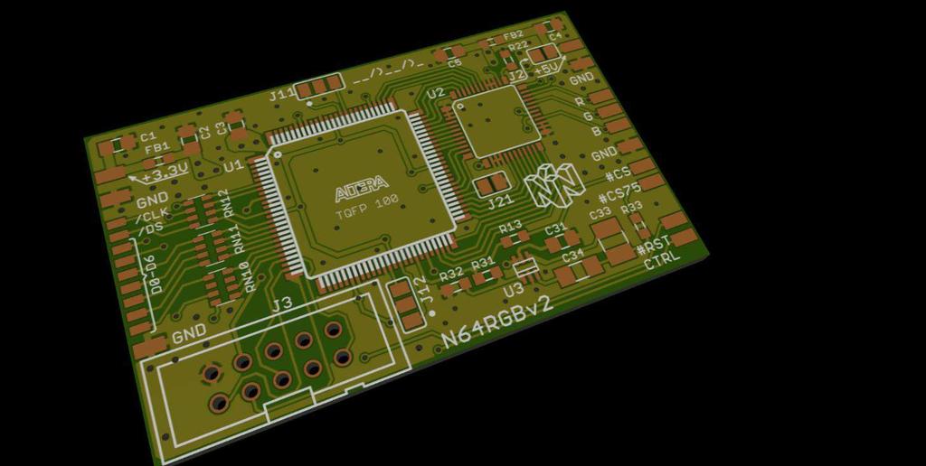
16 Solder Work Modding Kit -- N64 Advanced -- Reassemble the top RF shield and heat sink on top of the N64 mainboard Make sure that you do not squeeze any of the wires you prepared For that you cut and/or bend the taps of the RF shield Connect +3.3V and GND to the left hand side of the modding kit Connect the seven data lines and /DSYNC and /CLK to the appropriate pads Connect the wires for /Rst., Ctrl. (Controller) and /C (/Cold) to the pads at the bottom right of the modding kit Connect the video lines, GND and +5V to the right hand side of the modding kit
 and GND to the left hand side of the modding kit Connect the seven data lines and /DSYNC and /CLK to the appropriate pads Connect the wires for /Rst.")
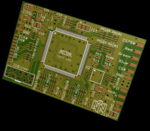
17 Solder Work Modding Kit -- N64RGB -- Reassemble the top RF shield and heat sink on top of the N64 mainboard Make sure that you do not squeeze any of the wires you prepared For that you cut and/or bend the taps of the RF shield Connect +3.3V (Vcc) and GND to the left hand side of the modding kit Connect the seven data lines and /DSYNC and /CLK to the appropriate pads Connect the wires for /Rst. and Ctrl. (Controller) to the pads at the bottom right of the modding kit Connect the video lines and GND to the right hand side of the modding kit You may want to use the Fil pad to toggle the LPF on and off (see jumper section)


18 Solder Work Modding Kit -- Some extra GND -- This screw is connected to a GND spacer This is a large GND plain To reduce the GND loop size, it is helpful to assemble some extra GND connections to the N64 mainboard If the GND is not properly designed between the N64 mainboard and modding kit some current out of the digital signals flows back to the N64 throgh the analog video connections. This causes visible noise! I assembled two extra connection: one on the left hand side of the modding PCB and one at the right hand side.
 Fallback Mode: - Fallback is active if reset button is pressed on powering on - fallback: 240p/480i and RGB output J3: Scanline")
19 Settings Solder Jumper (N64 Advanced) J5: 10pin JTAG interface for update firmware J4: Linemode J4.1: - opened: linedoubling enabled - closed: no linedoubling (beats J4.2) J4.2: - opened: 480i pass through - closed: 480i de-interlace (bob) Fallback Mode: - Fallback is active if reset button is pressed on powering on - fallback: 240p/480i and RGB output J3: Scanline strenght (J3.2/J3.1) = - (opened/opened): 0% - (opened/closed): 25% - (closed/opened): 50% - (closed / closed): 100% J1: VGA sync / Filter AddOn J1.1: - opened: output HS, VS and CS (VGA output possible) - closed: use filter addon J1.2: - Use filter board in bypass mode (e.g. to use it as a simple NTSC output to PAL output conversion) J6: Analog power supply (outdated) - leave J6 untouched and open!!! Use 5V power supply for analog part J2: RGB, RGsB, YPbPr J2.1: - opened: RGB output - closed: RGsB output J2.2: - opened: RGB / RGsB output - closed: YPbPr output (beats J2.1) Notes for dual jumper: - Jx.1 is always marked with a dot - Closed reference is middle pad

20 Settings Solder Jumper (N64 RGBv1) J1: (bottom side) - opened: use a CPLD with 240LEs - closed: use a CPLD with 570LEs Hidden Jumper between pin 36 and 37: - short both pins to activate 15bit mode by default J10: 10pin JTAG interface for update firmware Notes for dual jumper J11: - J11.1 is marked with a dot - Closed reference is middle pad J12: IGR / Mechanical Switches - opened: Use IGR (Ctrl. and /Rst) - closed: Use switches at M and A pads J11: De-Blur with IGR active J11.1: (only applicable with heuristic off) - opened: default de-blur on - closed: default de-blur off J11.2: - opened: use de-blur heuristic - closed: bypass de-blur heuristic Fil: Video filter - opened: Use filter of the THS grounded: THS7374 in bypass mode M: Manual (only with J12 closed) - opened: no de-blur or de-blur heuristic - grounded: de-blur in any 240p case (beats heuristic) A: Auto (only with J12 closed) - opened: bypass de-blur heuristic - grounded: use de-blur heuristic

21 Settings Solder Jumper (N64 RGBv2) J1: (bottom side) - opened: use a CPLD with 240LEs - closed: use a CPLD with 570LEs J2: (outdated and formerly J1) - leave J6 untouched and open!!! Use 5V power supply for analog part J3: 10pin JTAG interface for update firmware Notes for dual jumper J11: - J1#.1 is marked with a dot - Closed reference is middle pad J12.2: IGR / Mechanical Switches - opened: Use IGR (Ctrl. and /Rst) - closed: Use switches at M and A pads J12.1: 15bit mode default - opened: 15 bit mode off by default - closed: 15 bit mode on by default J11: De-Blur with IGR active J11.1: (only applicable with heuristic off) - opened: default de-blur on - closed: default de-blur off J11.2: - opened: use de-blur heuristic - closed: bypass de-blur heuristic J21: Sync on Green - opened: Don t use sync on green - closed: Output sync on green M: Manual (only with J12.1 closed) (#RST pad used for M) - opened: no de-blur or de-blur heuristic - grounded: de-blur in any 240p case (beats heuristic) A: Auto (only with J12.1 closed) (CTRL pad used for A) - opened: bypass de-blur heuristic - grounded: use de-blur heuristic
22 Cable Setup -- N64RGBv2 and N64 Advanced -- Name MultiAV SCART plug Ref. GND in SCART Cinch plugs Notes Red / Pr Red plug Using a 220uF cap in series is possible Green / Y Green plug Using a 220uF cap in series is possible Blue / Pb Blue plug Using a 220uF cap in series is possible Sync 3 or Not needed Consider notes on next page GND 5, 6 4, 5, 9, 13, 17, 18, 21 To outer ring of each plug Pin SCART plug is outer shield +5V Not needed Use a 180ohm resistor in series Audio left Red plug Audio right White plug
 to attenuate the signal for 75ohm terminationed destinations.")

23 Cable Setup -- N64RGBv2 and N64 Advanced -- Notes on Sync: I recommend using the 75ohm compatible csync output. If you do so then run a straight wire through your cable for sync. If you use TTL sync output, you have to add an additional resistor in series (N64RGv2: 0ohm to 900ohm; N64A: 270ohm to 1.1kohm) to attenuate the signal for 75ohm terminationed destinations. RGB cables: If you buy an RGB cable, buy a typical RGB cable for a NTSC SNES with sync on luma (MultiAV pin 7) or sync on csync (MultiAV pin 3). If you bought a raw csync cable and if you use the 75ohm output, remove / short the resistor which is possibly installed in the sync trace. RGsB / YPbPr Cables: With the given table you should be able to build your own component cable or to build an adapter (see pictures on left side) Unfortunately, there are no cables / adapter to bought.
 Solder the board onto the MultiAV and decide where /CS has to go pin 3 and/or pin 7 depending on your setup All connections to the N64RGBv2 and N64A are labeled A note on")
 Just use the Filter Addon board and use a 39Ohm resistor array at the output (marked with a red arrow) N64RGBv2 To use the LPF of the adapter board, left")
24 Cable Setup -- Filter Add On for the N64RGBv2 and N64 Advanced -- Use the Filter AddOn if your ADC device does not apply input filtering (e.g. some capture cards) Solder the board onto the MultiAV and decide where /CS has to go pin 3 and/or pin 7 depending on your setup All connections to the N64RGBv2 and N64A are labeled A note on PAL SNES RGB cables: By default the N64RGBv2 and N64A are not suitable to use it with PAL SNES RGB cables By using the Filter AddOn board one can convert the output such that it is possible to buy a stock PAL SNES RGB cable (with sync on luma) Just use the Filter Addon board and use a 39Ohm resistor array at the output (marked with a red arrow) N64RGBv2 To use the LPF of the adapter board, left F1 and F2 floating or connect them to GND To bypass the LPF, connect F1 and F2 pads to +5V. N64 Advanced: Remind to set J1.1 on the N64A Set J1.2 if you want to have the filter off, e.g. in the case you simply want to use a PAL SNES RGB cable (actually they will be set to 95MHz cut-off, which is way above the video content)
25 Cable Setup -- N64 RGBv1 -- Name MultiAV SCART plug Red Green Blue Ref. GND in SCART Notes PAL assembly NTSC assembly Use 75ohm resistor to reference GND Use 75ohm resistor to reference GND Use 75ohm resistor to reference GND Using a 220uF cap in series is possible Using a 220uF cap in series is possible Using a 220uF cap in series is possible Sync 3 or Consider notes on next page Using a 220uF cap in series is possible GND 5, 6 4, 5, 9, 13, 17, 18, 21 Pin SCART plug is outer shield +5V Use a 180ohm resistor in series Audio left Audio right
26 Cable Setup -- N64 RGBv1 -- PAL or NTSC assembly: Depends on RN20 PAL assembled kits have 39ohm resistor array installed NTSC assembled kits have 75ohm resistor array installed Notes on Sync: I recommend using the 75ohm compatible csync output. If you do so then run a straight wire through your cable for sync. For PAL assembly an optional resistor of 75ohm to reference GND can be installed. If you use TTL sync output, you have to add an additional resistor in series. R15 = 330ohm series resistor of size 0ohm to 420ohm R15 = 0ohm series resistor of size 330ohm to 750ohm RGB cables: It s possible to buy pre-build RGB cable with either PAL SNES or NTSC SNES setup. Use a cable with sync on luma (MultiAV pin 7) or sync on csync (MultiAV pin 3). If you bought a raw csync cable and if you use the 75ohm output, remove / short the resistor which is possibly installed in the sync trace.

27 Controller In Game Routines Z Basis for all button combinations R The controller is able to trigger a reset or to change deblur and 15bit mode option Button combinaton: Start + R + Z + A + B : trigger a reset C-ri : de-blur for 240p on C-le : de-blur for 240p off C-up : 15bit mode off C-dw : 15bit mode on Notes: Controller is only read if the actual game reads the controller Switching de-blur overwrites the heuristic estimation. De-blur option is reset with each triggered reset and power cycle 15bit mode is reset with each power cycle

 3. Go to Additional Software 4.")

28 Firmwareupdate -- Download the software tools Go to altera.com and select Downloads from the SUPPORT menu 2. Select Download from the Light Edition column of the Design Software (preselected) 3. Go to Additional Software 4. Download the Quartus Prime Programmer and Tools software If you have the Quartus Prime edition installed, the programmer tools are already available on your computer. Date: Website layout may change

29 Firmwareupdate -- Update your N64 Advanced -- Connect your PC with the USB Blaster and the USB Blaster with the modding kit J5 Download the actual firmware build from the GitHub repository folder advancedrgbmod/firmware/output_files/yourfpga/n64 a_yourfpga.jic Open the programmer tool Load the previously downlaoded JIC file with Add File Check Program/Configure for the FPGA and Program/Configure and Verify for the Flashdevice Make sure that the USB Blaster is selected in the Hardware Setup Click on Start (the N64 has to be powered for the reference voltage) and wait for the process to be finished Power cycle your N64 and enjoy :) Quartus Prime Lite v17.1

30 Firmwareupdate -- Update your N64 RGB -- Connect your PC with the USB Blaster and the USB Blaster with the modding kit J10 Download the actual firmware build from the GitHub repository folder generalrgbmod/firmware/output_files/v#/n64rgb_yourcpld.pof Open the programmer tool Load the previously downlaoded POF file with Add File Check Program/Configure and Verify for the CFM part of your device Make sure that the USB Blaster is selected in the Hardware Setup Click on Start (the N64 has to be powered for the reference voltage) and wait for the process to be finished Quartus Prime Lite v17.1
Sega MegaDrive 1 RGB Bypass Installation Guide Rev 1.1
 Sega MegaDrive 1 RGB Bypass Installation Guide Rev 1.1 This step by step guide describes the Installation of the open source Voultar RGB Bypass Amplifier board for the original SEGA MegaDrive/Genesis 1.
DIY Guide - Building Franky v1.1, the SEGA Audio and Videocard for MSX
 DIY Guide - Building Franky v1.1, the SEGA Audio and Videocard for MSX 2015 FRS & MSXpró. Translation by FRS and Supersoniqs. Table of Contents Introduction... 3 Materials needed... 3 Audio volume boost...
Notice technique / Technical manual NT Ind A 14/26. SONY FCB H11 and FCB EH4300 SDI Interface module. Technical manual
 Notice technique / Technical manual NT10 0301 Ind A 14/26 SONY FCB H11 and FCB EH4300 SDI Interface module Technical manual Notice technique / Technical manual NT10 0301 Ind A 15/26 Sommaire 1 Presentation...
SPECIFICATION FOR APPROVAL
 SPECIFICATION FOR APPROVAL (ANALOG RGB AND VIDEO INTERFACE CONTROLLER FOR VGA/SVGA/XGA RESOLUTION TFT-LCDs) MODEL NO : AP4300 SERIES BUYER S PARTNO: APPROVED REFERENCE (PLEASE RETURN ONE OF THESE TO US
UAV Ultimate Atari Video A7800
 UAV Ultimate Atari Video A7800 Basic Install guide because this is really easy mod to do! The UAV is a wonderful piece of tech for what it can do. To summarize, the UAV is a replacement video encoder and
NewScope-7A Operating Manual
 2016 SIMMCONN Labs, LLC All rights reserved NewScope-7A Operating Manual Preliminary May 13, 2017 NewScope-7A Operating Manual 1 Introduction... 3 1.1 Kit compatibility... 3 2 Initial Inspection... 3 3
Atari 400/800 Super Color CPU Card
 Installation Instructions Atari 400/800 Super Color CPU Card Date: 2017, May 3 rd, version 1.1 Author: Jürgen van Radecke (tfhh) Introduction Hi, Thank you for your purchase of a Super Colour CPU Card!
Super-Doubler Device for Improved Classic Videogame Console Output
 Super-Doubler Device for Improved Classic Videogame Console Output Initial Project Documentation EEL4914 Dr. Samuel Richie and Dr. Lei Wei September 15, 2015 Group 31 Stephen Williams BSEE Kenneth Richardson
Fixed Audio Output for the K2 Don Wilhelm (W3FPR) & Tom Hammond (NØSS) v August 2009
 & Tom Hammond (NØSS) v August 2009") Fixed Audio Output for the K2 Don Wilhelm (W3FPR) & Tom Hammond (NØSS) v. 2.1 06 August 2009 I have had several requests to provide a fixed audio output from the K2. After looking at the circuits that
Fixed Audio Output for the K2 Don Wilhelm (W3FPR) & Tom Hammond (NØSS) v. 2.1 06 August 2009 I have had several requests to provide a fixed audio output from the K2. After looking at the circuits that
AD9884A Evaluation Kit Documentation
 a (centimeters) AD9884A Evaluation Kit Documentation Includes Documentation for: - AD9884A Evaluation Board - SXGA Panel Driver Board Rev 0 1/4/2000 Evaluation Board Documentation For the AD9884A Purpose
MAKE AN RGB CONTROL KNOB.
 MAKE AN RGB CONTROL KNOB. This is a knob based colour changing controller that uses a custom programmed microcontroller to pack a lot of features into a small affordable kit. The module can drive up to
DDS VFO CONSTRUCTION MANUAL. DDS VFO Construction Manual Issue 1.1 Page 1
 DDS VFO CONSTRUCTION MANUAL DDS VFO Construction Manual Issue 1.1 Page 1 Important Please read before starting assembly STATIC PRECAUTION The DDS VFO kit contains the following components which can be
This is a support manual for the GBS-8220 which comes in a one vga port and two port version.
 This is a support manual for the GBS-8220 which comes in a one vga port and two port version. When using this board you want to read all the information in this document there are many common mistakes/issues
Atari PICO Composite Mod Board Installation Instructions:
 Atari PICO Composite Mod Board Installation Instructions: Installation Guide 6 Switch Atari 2600 6 Switch Video Mod Installation Guide Disclaimer: I am not responsible for any damage done to your Atari.
TeamWork Kits Installation Guide
 TX 0 RX COM +5V APARATUS US TeamWork Kits Installation Guide TeamWork 400 and TeamWork 600 Kits The TeamWork 400 and TeamWork 600 kits consist of an HDMI switcher, system controller, Cable Cubby, and cables
Booya16 SDR Datasheet
 Booya16 SDR Radio Receiver Description The Booya16 SDR radio receiver samples RF signals at 16MHz with 14 bits and streams the sampled signal into PC memory continuously in real time. The Booya software
Software Analog Video Inputs
 Software FG-38-II has signed drivers for 32-bit and 64-bit Microsoft Windows. The standard interfaces such as Microsoft Video for Windows / WDM and Twain are supported to use third party video software.
Introduction 1. Green status LED, controlled by output signal ST. Sounder, controlled by output signal Q6. Push switch on input D6
 Introduction 1 Welcome to the GENIE microcontroller system! The activity kit allows you to experiment with a wide variety of inputs and outputs... so why not try reading sensors, controlling lights or
Interfaces and Sync Processors
 Interfaces and Sync Processors Kramer Electronics has a full line of video, audio and sync interfaces. The group is divided into two sections Format Interfaces and Video Sync Processors. The Format Interface
Multi-Key v2.4 Multi-Function Amplifier Keying Interface
 Multi-Key v2.4 Multi-Function Amplifier Keying Interface ASSEMBLY & OPERATION INSTRUCTIONS INTRODUCTION The Harbach Electronics, LLC Multi-Key is a multi-function external device designed for the safe
SDI Development Kit using National Semiconductor s LMH0340 serializer and LMH0341 deserializer
 User Guide: SDALTEVK HSMC SDI ADAPTER BOARD 9-Jul-09 Version 0.06 SDI Development Kit using National Semiconductor s LMH0340 serializer and LMH0341 deserializer Page 1 of 31 1...Overview 3 2...Evaluation
Dual PAL or NTSC Video to RGB Converter (One way) with 12V Relay Switch Operation Manual
 with 12V Relay Switch Operation Manual") Dual PAL or NTSC Video to RGB Converter (One way) with 12V Relay Switch Operation Manual Introduction This unit converts video signals from NTSC/PAL/SECAM into RGB/Sync or RGsB (Sync On Green) to allow
Dual PAL or NTSC Video to RGB Converter (One way) with 12V Relay Switch Operation Manual Introduction This unit converts video signals from NTSC/PAL/SECAM into RGB/Sync or RGsB (Sync On Green) to allow
Chrontel CH7015 SDTV / HDTV Encoder
 Chrontel Preliminary Brief Datasheet Chrontel SDTV / HDTV Encoder Features 1.0 GENERAL DESCRIPTION VGA to SDTV conversion supporting graphics resolutions up to 104x768 Analog YPrPb or YCrCb outputs for
DM1624, DM1612, DM812
 Installation Guide Hardware and Software DM Series Digital Processors models DM1624, DM1612, DM812 LECTROSONICS, INC. 1 Installation Specific Information Only This guide covers only installation related
Commissioning Guide. firepickdelta. Commissioning Guide. Written By: Neil Jansen firepickdelta.dozuki.com Page 1 of 22
 firepickdelta Commissioning Guide Written By: Neil Jansen 2017 firepickdelta.dozuki.com Page 1 of 22 Step 1 Pre-Requisites Before commissioning, please make sure ALL of the following steps have been completed,
TV Synchronism Generation with PIC Microcontroller
 TV Synchronism Generation with PIC Microcontroller With the widespread conversion of the TV transmission and coding standards, from the early analog (NTSC, PAL, SECAM) systems to the modern digital formats
Quick Start Guide Revision 1A
 Quick Start Guide Revision 1A This document is copyright ACEL Systems Ltd 2017 All rights reserved worldwide VideoGameperfection.com is a trading name of ACEL Systems Ltd Registered in England number 10981211
DM-TX-201-C DigitalMedia 8G+ Transmitter. Supplemental Guide Crestron Electronics, Inc.
 DM-TX-201-C DigitalMedia 8G+ Transmitter Supplemental Guide Crestron Electronics, Inc. The product warranty can be found at www.crestron.com/warranty. The specific patents that cover Crestron products
W0EB/W2CTX DSP Audio Filter Operating Manual V1.12
 W0EB/W2CTX DSP Audio Filter Operating Manual V1.12 Manual and photographs Copyright W0EB/W2CTX, March 13, 2019. This document may be freely copied and distributed so long as no changes are made and the
Step What to do Expected result What to do if test fails Component tested 1 Visual inspection. Board is accurately assembled
 Fox Delta Amateur Radio Projects & Kits AAZ-0914A 50MHZ Antenna Analyzer Testing Guide by Tony / I2TZK SWR Analyzer 4 steps for a quick test Step What to do Expected result What to do if test fails Component
How To Build Megavolt s Small Buffered JTAG v1.2
 How To Build Megavolt s Small Buffered JTAG v1.2 Abstract A JTAG cable should be considered mandatory equipment for any serious tester. It provides a means to backup the information in the receiver and
Entry Level Tool II. Reference Manual. System Level Solutions, Inc. (USA) Murphy Avenue San Martin, CA (408) Version : 1.0.
 Murphy Avenue San Martin, CA (408) Version : 1.0.") Entry Level Tool II Reference Manual, Inc. (USA) 14100 Murphy Avenue San Martin, CA 95046 (408) 852-0067 http://www.slscorp.com Version : 1.0.3 Date : October 7, 2005 Copyright 2005-2006,, Inc. (SLS) All
Entry Level Tool II Reference Manual, Inc. (USA) 14100 Murphy Avenue San Martin, CA 95046 (408) 852-0067 http://www.slscorp.com Version : 1.0.3 Date : October 7, 2005 Copyright 2005-2006,, Inc. (SLS) All
Ten-Tec (865) Service Department:(865)
 Service Department:(865)") Ten-Tec (865) 453-7172 Service Department:(865) 428-0364 Installation Instructions for Ten-Tec Jupiter AT538K Tuner Kit The installation of the AT538K is divided into two steps. The first step is to reprogram
Ten-Tec (865) 453-7172 Service Department:(865) 428-0364 Installation Instructions for Ten-Tec Jupiter AT538K Tuner Kit The installation of the AT538K is divided into two steps. The first step is to reprogram
Pandora rev6a testing:
 Testing the EVB: - 4-bit SDIO interface taken directly from pads on Pandora PCB where wifi module would be - Other digital lines taken directly from pads on Pandora PCB: IRQ, RESETX/PMEN - Main power input
PART. Maxim Integrated Products 1
 9-646; Rev 0; /00 General Description The MAX94 evaluation kit (EV kit) is assembled with a MAX94 and the basic components necessary to evaluate the -bit analog-to-digital converter (ADC). Connectors for
Pablo II. The Picasso IV video-encoder. Manual. 18 August Copyright c 1997 Village Tronic Marketing GmbH Mühlenstraße Sarstedt Germany
 Pablo II The Picasso IV video-encoder Manual 18 August 1997 Copyright c 1997 Village Tronic Marketing GmbH Mühlenstraße 2 31157 Sarstedt Germany Technical Hotline: Tel. +49 (0)5066 / 7013-10 FAX: Tel.
Mal-2 assembly guide v1.0
 Mal-2 assembly guide v.0 SONIC POTIONS Schematic and BOM The BOM can be found on Google Docs Prepare the PCB Separate the PCBs using some pliers. PCB We start with the lower PCB and assemble it beginning
QUICK START GUIDE FOR DEMONSTRATION CIRCUIT /12/14 BIT 10 TO 65 MSPS DUAL ADC
 LTC2286, LTC2287, LTC2288, LTC2290, LTC2291, LTC2292, LTC2293, LTC2294, LTC2295, LTC2296, LTC2297, LTC2298 or LTC2299 DESCRIPTION Demonstration circuit 816 supports a family of s. Each assembly features
Experiment # 4 Counters and Logic Analyzer
 EE20L - Introduction to Digital Circuits Experiment # 4. Synopsis: Experiment # 4 Counters and Logic Analyzer In this lab we will build an up-counter and a down-counter using 74LS76A - Flip Flops. The
Lab 7: Soldering - Traffic Light Controller ReadMeFirst
 Lab 7: Soldering - Traffic Light Controller ReadMeFirst Lab Summary The two-way traffic light controller provides you with a quick project to learn basic soldering skills. Grading for the project has been
Mini-Yack Iambic Keyer
 Mini-Yack Iambic Keyer Assembly Instructions Mini-Yack is a "bare bones" Iambic keyer for embedding into QRP and home brew equipment. The keyer has the following features: Keying from 1-50WPM YACK memory
3G HDSDI interface board for SONY FCB HD cameras. Technical manual
 3G HDSDI interface board for SONY FCB HD cameras Technical manual Revision History Date Modifications Pages Oct, 9th, 2013 Original All 1 Board description This board provides a 3G HDSDI output for FCB
DOGM GRAPHIC SERIES 128x64 DOTS
 DOGM GRAPHIC SERIES 128x64 DOTS 27.6.2007 available from 1 pc. off! flat: 5.6mm incl. LED TECHNICAL DATA EA DOGM128W-6 + EA LED55x46-A EA DOGM128B-6 + EA LED55x46-W EA DOGM128W-6 + EA LED55x46-W * HIGH-CONTRAST
DIY KIT MHZ 8-DIGIT FREQUENCY METER
 This kit is a stand-alone frequency meter capable of measuring repetitive signals up to a frequency of 50MHz. It has two frequency ranges (15 and 50 MHz) as well as two sampling rates (0.1 and 1 second).
9 Analyzing Digital Sources and Cables
 9 Analyzing Digital Sources and Cables Topics in this chapter: Getting started Measuring timing of video signal Testing cables and distribution systems Testing video signal quality from a source Testing
Model 6010 Four Channel 20-Bit Audio ADC Data Pack
 Model 6010 Four Channel 20-Bit Audio ADC Data Pack Revision 3.1 SW v1.0.0 This data pack provides detailed installation, configuration and operation information for the Model 6010 Four Channel 20-bit Audio
DX-10 tm Digital Interface User s Guide
 DX-10 tm Digital Interface User s Guide GPIO Communications Revision B Copyright Component Engineering, All Rights Reserved Table of Contents Foreword... 2 Introduction... 3 What s in the Box... 3 What
Instruction Manual. Series 3000 Model R-165A. Audio/Video IF/RF Relay Panel. CATV Switching and Control
 Series 3000 Model R-165A Audio/Video IF/RF Relay Panel Instruction Manual CATV Switching and Control 585-765-2254 fax 585-765-9330 100 Housel Ave. Lyndonville NY 14098 www.monroe-electronics.com Table
LED Array Board.
 LED Array Board www.matrixtsl.com EB087 Contents About This Document 2 General Information 3 Board Layout 4 Testing This Product 5 Circuit Description 6 Circuit Diagram 7 About This Document This document
Pelican PL-957. Adding additional Tos Link (Digital Optical) inputs, and / or IR Remote
 inputs, and / or IR Remote") Pelican PL-957 Adding additional Tos Link (Digital Optical) inputs, and / or IR Remote Table of Contents: Background;... 2 Section 1: Adding TosLink receivers... 3 Section 2: Adding Remote Capability...
Pelican PL-957 Adding additional Tos Link (Digital Optical) inputs, and / or IR Remote Table of Contents: Background;... 2 Section 1: Adding TosLink receivers... 3 Section 2: Adding Remote Capability...
Design and Implementation of an AHB VGA Peripheral
 Design and Implementation of an AHB VGA Peripheral 1 Module Overview Learn about VGA interface; Design and implement an AHB VGA peripheral; Program the peripheral using assembly; Lab Demonstration. System
DA IN 1-OUT LINE DRIVER WITH EQUALIZATION + AUDIO USER S GUIDE
 MANUAL PART NUMBER: 400-0430-001 1-IN 1-OUT LINE DRIVER WITH UALIZATION + AUDIO USER S GUIDE TABLE OF CONTENTS Page PRECAUTIONS / SAFETY WARNINGS... 2 GENERAL...2 GUIDELINES FOR RACK-MOUNTING...2 INSTALLATION...2
DOGM GRAPHIC SERIES. 128x64, 3.3V available in low quantity! flat: 5.6mm with LED b./l. mounted TECHNICAL DATA ORDERING CODE ACCESSORIES
 Issue 10.2014 DOGM GRAPHIC SERIES 128x64, 3.3V available in low quantity! flat: 5.6mm with LED b./l. mounted EA DOGM128W-6 + EA LED55x46-A EA DOGM128B-6 + EA LED55x46-W EA DOGM128W-6 + EA LED55x46-W TECHNICAL
Laboratory Exercise 4
 Laboratory Exercise 4 Polling and Interrupts The purpose of this exercise is to learn how to send and receive data to/from I/O devices. There are two methods used to indicate whether or not data can be
Important Health Warning About Playing Video Games
 Contents Important Health Warning About Playing Video Games... 3 Please Read... 4 Analogue Nt diagram... 5-6 Hardware Features... 7-11 HDMI Upgrade Features... 12-13 Video Options... 14-17 Audio Options...
Arria-V FPGA interface to DAC/ADC Demo
 Arria-V FPGA interface to DAC/ADC Demo 1. Scope Demonstrate Arria-V FPGA on dev.kit communicates to TI High-Speed DAC and ADC Demonstrate signal path from DAC to ADC is operating as part of the signal
ivw-ud322 / ivw-ud322f
 ivw-ud322 / ivw-ud322f Video Wall Controller Supports 2 x 2, 2 x 1, 3 x 1, 1 x 3, 4 x 1 & 1 x 4 Video Wall Array User Manual Rev. 1.01 i Notice Thank you for choosing inds products! This user manual provides
APPLICATION NOTE 4312 Getting Started with DeepCover Secure Microcontroller (MAXQ1850) EV KIT and the CrossWorks Compiler for the MAXQ30
 EV KIT and the CrossWorks Compiler for the MAXQ30") Maxim > Design Support > Technical Documents > Application Notes > Microcontrollers > APP 4312 Keywords: MAXQ1850, MAXQ1103, DS5250, DS5002, microcontroller, secure microcontroller, uc, DES, 3DES, RSA,
Maxim > Design Support > Technical Documents > Application Notes > Microcontrollers > APP 4312 Keywords: MAXQ1850, MAXQ1103, DS5250, DS5002, microcontroller, secure microcontroller, uc, DES, 3DES, RSA,
EA DOGL128x-6 EA LED68X51-RGB
 Issue 5.2014 EA DOGL128-6 GRAPHIC 128x64 DOTS, 3.3V also available in low quantity! flat: 6.5mm with LED B/L mounted EA DOGL128W-6 + EA LED68x51-W EA DOGL128B-6 + EA LED68x51-W EA DOGL128W-6 + EA LED68x51-A
TL7050 Dual 3G/HD-SDI + DVI(HDMI) Output Video Transceiver. TL Features. Block Diagram TL7050
 Output Video Transceiver. TL Features. Block Diagram TL7050") 3G ishot XBlock is a family of small form factor modules for formatting & converting gene ric digital video streams to standard compliant formats. Different interface standards are supported from the transmitter
3G ishot XBlock is a family of small form factor modules for formatting & converting gene ric digital video streams to standard compliant formats. Different interface standards are supported from the transmitter
MBUS 10 RS232 TO MBUS LEVEL CONVERTER
 Media and protocol converters MBUS 10 RS232 TO MBUS LEVEL CONVERTER RS232 to MBus level conversion Maximum 10 MBus slaves Baud Rate: 300 to 19200 bps RS232 MBus opto isolation Over-current and short-circuit
Genboard v3 Official build and test guide
 Genboard v3 Official build and test guide 1 Contents: 1 Preparations 2 Assembly 2.1 Checking the PCB 2.2 General parts 2.2.1 EGT/knock 2.2.2 Supply connection, fuse wire 2.2.3 Stepper 2.2.4 Filter inductance
XTAL Bank DDS Version 0.02 Sept Preliminary, highly likely to contain numerous errors
 XTAL Bank DDS Version 002 Sept 7 2012 Preliminary, highly likely to contain numerous errors The photo above shows the fully assembled Xtal Bank DDS with 2 DDS modules installed (The kit is normally only
TKEY-K16. Touch CW automatic electronic keyer. (No moving parts no contacts) Assembly manual. Last review: March 15, 2018
 Assembly manual. Last review: March 15, 2018") TKEY-K16 Touch CW automatic electronic keyer (No moving parts no contacts) Assembly manual Last review: March 15, 2018 Commands and use manual of the K16 and Updates and news: www.ea3gcy.com Thanks for
TKEY-K16 Touch CW automatic electronic keyer (No moving parts no contacts) Assembly manual Last review: March 15, 2018 Commands and use manual of the K16 and Updates and news: www.ea3gcy.com Thanks for
Document Part Number: Copyright 2010, Corelis Inc.
 CORELIS Low Voltage Adapter Low Voltage Adapter Boundary-Scan Interface User s Manual Document Part Number: 70398 Copyright 2010, Corelis Inc. Corelis, Inc. 12607 Hiddencreek Way Cerritos, CA 90703-2146
Using SignalTap II in the Quartus II Software
 White Paper Using SignalTap II in the Quartus II Software Introduction The SignalTap II embedded logic analyzer, available exclusively in the Altera Quartus II software version 2.1, helps reduce verification
Teletext Inserter Firmware. User s Manual. Contents
 Teletext Inserter Firmware User s Manual Contents 0 Definition 3 1 Frontpanel 3 1.1 Status Screen.............. 3 1.2 Configuration Menu........... 4 2 Controlling the Teletext Inserter via RS232 4 2.1
NanoCom ADS-B. Datasheet An ADS-B receiver for space applications
 NanoCom ADS-B Datasheet An ADS-B receiver for space applications 1 Table of contents 1 TABLE OF CONTENTS... 2 2 CHANGELOG... 3 3 INTRODUCTION... 4 4 OVERVIEW... 4 4.1 HIGHLIGHTED FEATURES... 4 4.2 BLOCK
Build Your Own Clone Super 8 Kit Instructions
 Build Your Own Clone Super 8 Kit Instructions Warranty: BYOC, Inc. guarantees that your kit will be complete and that all parts and components will arrive as described, functioning and free of defect.
DEM 9ULNACK 3.4 GHz. PHEMT LNA amplifier complete kit assembly guide
 DEM 9ULNACK 3.4 GHz. PHEMT LNA amplifier complete kit assembly guide SPECIFICATIONS Noise Figure: < 0.8 db Gain: > 15 db Frequency Range: 3400-3500 MHz Input Voltage: 7-16 VDC Description: The 9ULNACK
INSTALLATION AND OPERATION INSTRUCTIONS EVOLUTION VIDEO DISTRIBUTION SYSTEM
 INSTALLATION AND OPERATION INSTRUCTIONS EVOLUTION VIDEO DISTRIBUTION SYSTEM ATTENTION: READ THE ENTIRE INSTRUCTION SHEET BEFORE STARTING THE INSTALLATION PROCESS. WARNING! Do not begin to install your
CH7021A SDTV / HDTV Encoder
 Chrontel SDTV / HDTV Encoder Brief Datasheet Features VGA to SDTV/EDTV/HDTV conversion supporting graphics resolutions up to 1600x1200 HDTV support for 480p, 576p, 720p, 1080i and 1080p Support for NTSC,
CoLinkEx JTAG/SWD adapter USER MANUAL
 CoLinkEx JTAG/SWD adapter USER MANUAL rev. A Website: www.bravekit.com Contents Introduction... 3 1. Features of CoLinkEX adapter:... 3 2. Elements of CoLinkEx programmer... 3 2.1. LEDs description....
VT320X Large Screen Outdoor LCD
 Solutions for Demanding Applications VARTECH S Y S T E M S I N C. Industrial CRT and Flat Panel Displays VT320X Large Screen Outdoor LCD User s Guide Read these instructions completely before attempting
User Manual MODEL: KKF1500-PCAP. True FLAT P-CAP LCD Monitor. Installation Guide. 15 True FLAT P-CAP Touch LCD Monitor
 True FLAT P-CAP LCD Monitor User Manual Installation Guide 15 True FLAT P-CAP Touch LCD Monitor MODEL: KKF1500-PCAP i-tech Company LLC TOLL FREE: (888) 483-2418 EMAIL: info@itechlcd.com WEB: www.itechlcd.com
DS-7200HVI/HFI-SH Series DVR Quick Operation Guide
 DS-7200HVI/HFI-SH Series DVR Quick Operation Guide UD.6L0202B0019A01 Thank you for purchasing our product. If there is any question or request, please do not hesitate to contact dealer. This manual is
Lab 7: Soldering - Traffic Light Controller ReadMeFirst
 Lab 7: Soldering - Traffic Light Controller ReadMeFirst Lab Summary The two way traffic light controller provides you with a quick project to learn basic soldering skills. Grading for the project has been
TL7050 Dual 3G/HD-SDI + DVI(HDMI) Output Video Transceiver. TL Features. Block Diagram TL7050. Dual 3G-SDI + DVI(HDMI) Output
 Output Video Transceiver. TL Features. Block Diagram TL7050. Dual 3G-SDI + DVI(HDMI) Output") Thunder Link is a family of small form factor modules for formatting and converting generic digital video streams to standard compliant formats. Different interface standards are supported from the transmitter
Thunder Link is a family of small form factor modules for formatting and converting generic digital video streams to standard compliant formats. Different interface standards are supported from the transmitter
ImproX (TRT) Twin Remote Terminal INSTALLATION MANUAL
 Twin Remote Terminal INSTALLATION MANUAL") SPECIFICATIONS MODEL NUMBER: XRT910-0-0-GB-XX XRT911-0-0-GB-XX XTT911-0-0-NN-XX IMPROX TRT ImproX (TRT) Twin Remote Terminal INSTALLATION MANUAL Working Environment XRT910-0-0-GB-XX... (Aluminium Extruded
SPECIFICATIONS MODEL NUMBER: XRT910-0-0-GB-XX XRT911-0-0-GB-XX XTT911-0-0-NN-XX IMPROX TRT ImproX (TRT) Twin Remote Terminal INSTALLATION MANUAL Working Environment XRT910-0-0-GB-XX... (Aluminium Extruded
ESI VLS-2000 Video Line Scaler
 ESI VLS-2000 Video Line Scaler Operating Manual Version 1.2 October 3, 2003 ESI VLS-2000 Video Line Scaler Operating Manual Page 1 TABLE OF CONTENTS 1. INTRODUCTION...4 2. INSTALLATION AND SETUP...5 2.1.Connections...5
EVD-L04/100A1-960, EVD-L08/200A1-960 and. EVD-L16/400A1-960 DVRs. Quick Operation Guide
 EVD-L04/100A1-960, EVD-L08/200A1-960 and EVD-L16/400A1-960 DVRs Quick Operation Guide Thank you for purchasing our product. If there is any question or request, please do not hesitate to contact dealer.
QUICK START GUIDE FOR DEMONSTRATION CIRCUIT /12/14 BIT 10 TO 105 MSPS ADC
 LTC2280, LTC2282, LTC2284, LTC2286, LTC2287, LTC2288 LTC2289, LTC2290, LTC2291, LTC2292, LTC2293, LTC2294, LTC2295, LTC2296, LTC2297, LTC2298 or LTC2299 DESCRIPTION Demonstration circuit 851 supports a
SignalTap Plus System Analyzer
 SignalTap Plus System Analyzer June 2000, ver. 1 Data Sheet Features Simultaneous internal programmable logic device (PLD) and external (board-level) logic analysis 32-channel external logic analyzer 166
TECHNICAL SUPPORT , or FD151CV-LP Installation and Operation Manual 15.1 Low Profile LCD
 TECHNICAL SUPPORT 678-867-6717, or www.flightdisplay.com FD151CV-LP Installation and Operation Manual 15.1 Low Profile LCD FD151CV-LP 15.1" Low Profile LCD 2006 Flight Display Systems. All Rights Reserved.
Table of Contents Introduction
 Page 1/9 Waveforms 2015 tutorial 3-Jan-18 Table of Contents Introduction Introduction to DAD/NAD and Waveforms 2015... 2 Digital Functions Static I/O... 2 LEDs... 2 Buttons... 2 Switches... 2 Pattern Generator...
Field Service Procedure Replacement GACP Control Panel Kit, ST24
 1. Brief Summary: Troubleshooting document for diagnosing a fault with and replacing the Graphic Antenna Control Panel (GACP) for the ST24 antenna. 2. Checklist: Verify Power to the GACP Verify Communications
Tube Cricket Build Guide
 Tube Cricket Build Guide The Tube Cricket is a small-wattage amp that puts out about 1 watt of audio power. With a 12AU7 tube-preamp and a JRC386 power amp, the Tube Cricket gives you great tone in a compact
DE2-115/FGPA README. 1. Running the DE2-115 for basic operation. 2. The code/project files. Project Files
 DE2-115/FGPA README For questions email: jeff.nicholls.63@gmail.com (do not hesitate!) This document serves the purpose of providing additional information to anyone interested in operating the DE2-115
ISC0904: 1k x 1k 18µm N-on-P ROIC. Specification January 13, 2012
 ISC0904 1k x 1k 18µm N-on-P ROIC Specification January 13, 2012 This presentation contains content that is proprietary to FLIR Systems. Information is subject to change without notice. 1 Version 1.00 January
RAKK dac. RAKK dac Mark IV. RAKK dac Mark IV. Assembly and Installation Manual
 RAKK dac RAKK dac Mark IV RAKK dac Mark IV Assembly and Installation Manual Version 1.3 2013-2014 Raleigh Audio version Use this manual with RAKK dac Mark IV v 2.0, which is marked on the board. Required
PR-101 STEREO PREAMPLIFIER Phono Preamp ASSEMBLY MANUAL
 PR-101 STEREO PREAMPLIFIER Phono Preamp ASSEMBLY MANUAL 2016 AkitikA LLC All rights reserved Revision 1p18 March 12, 2016 Page 1 of 24 Table of Contents Table of Contents... 2 Table of Figures... 2 Section
AN 848: Implementing Intel Cyclone 10 GX Triple-Rate SDI II with Nextera FMC Daughter Card Reference Design
 AN 848: Implementing Intel Cyclone 10 GX Triple-Rate SDI II with Nextera FMC Daughter Card Reference Design Updated for Intel Quartus Prime Design Suite: 18.0 Subscribe Send Feedback Latest document on
Introduction 1. Digital inputs D6 and D7. Battery connects here (red wire to +V, black wire to 0V )
") Introduction 1 Welcome to the magical world of GENIE! The project board is ideal when you want to add intelligence to other design or electronics projects. Simply wire up your inputs and outputs and away
Introduction 1 Welcome to the magical world of GENIE! The project board is ideal when you want to add intelligence to other design or electronics projects. Simply wire up your inputs and outputs and away
Contents Section 9, Illustrated Parts
 Contents Section 9, Illustrated Parts Figures 9-1. Parts of RT7... 9-5 9-2. RT7 Drive Assembly... 9-9 9-3. RT7 Refrigeration System... 9-10 9-4. Parts of RT7 PLUS... 9-15 9-5. RT7 PLUS Drive Assembly...
AI-1664LAX-USB. Features. 100KSPS 16-bit Analog Input Unit for USB AI-1664LAX-USB 1. Ver.1.01
 100KSPS 16-bit Analog Unit for USB AI-1664LAX-USB * Specifications, color and design of the products are subject to change without notice. This product is a USB2.0-compliant analog input unit that extends
AD16-64(LPCI)LA. Non-isolated high precision analog input board for Low Profile PCI AD16-64(LPCI)LA 1. Ver.1.01
LA. Non-isolated high precision analog input board for Low Profile PCI AD16-64(LPCI)LA 1. Ver.1.01") Non-isolated high precision analog board for Low Profile PCI AD16-64(LPCI)LA * Specifications, color and design of the products are subject to change without notice. This product is a PCI bus compatible
Non-isolated high precision analog board for Low Profile PCI AD16-64(LPCI)LA * Specifications, color and design of the products are subject to change without notice. This product is a PCI bus compatible
7 SEGMENT LED DISPLAY KIT
 ESSENTIAL INFORMATION BUILD INSTRUCTIONS CHECKING YOUR PCB & FAULT-FINDING MECHANICAL DETAILS HOW THE KIT WORKS CREATE YOUR OWN SCORE BOARD WITH THIS 7 SEGMENT LED DISPLAY KIT Version 2.0 Which pages of
TL6050 / TL6051 / TL6052 Datasheet - HDMI/HD-SDI Output Video Transceiver. TL605x - Features. Block Diagram TL605x.
 Thunder Link is a family of small form factor modules for formatting and converting generic digital video streams to standard compliant formats. Different interface standards are supported from the transmitter
TeamWork Installation Guide
 C G G 00-0V/ A MAX TX RX +V APARATUS US 0 TeamWork Installation Guide TeamWork TeamWork is a fully customizable collaboration system comprised of an switcher, Show Me cables, a control processor, and a
TRIMBLE GPS / 10MHz REFERENCE MONITOR DISPLAY V January 2015
 TRIMBLE GPS / 10MHz REFERENCE MONITOR DISPLAY V1.2-1.4 January 2015 A display and command module for the Trimble Thunderbolt GPS with 10MHz reference oscillator. by Hubbatech Software Revision Notes: 1.2-2014