DVB-S2 Meter. smartmeter S20. User Manual. Version: English
|
|
|
- Evelyn Nash
- 5 years ago
- Views:
Transcription


1 DVB-S2 Meter smartmeter S20 User Manual Version: English
2 User Information Preface Dear Customer, Thank you for purchasing the digital DVB-S meter smartmeter S20. This user manual contains all the information required to connect, to operate, to clean, and to dispose of the device. Please read the user manual carefully before you start using the meter. smart electronic GmbH Industriestraße St. Georgen Germany Service Hotline: +49 (0) Telefax: +49 (0) Internet: smart electronic GmbH 2013 All rights, technical changes, errors as well as printing mistakes reserved. Any reproducing or copying of the contents requires prior written permission from smart. 2 smartmeter S20
3 User Information Contents 1 User Information Use of this Manual Signs, Symbols, Layout Product Description Scope of Delivery Meter Guarantee Safety Notes Safety of persons Appropriate Usage Hazards from Improper Use Lithium Polymer Battery Initial Setup Charging the Battery Switching the Meter On and Off Entering and Exiting the Menu Navigating through the Menu Aligning the Satellite Dish Menu TP Search Renaming a Satellite Adding a Satellite Deleting a Satellite Searching for a Transponder Deleting a Transponder Adding a Transponder Searching Channels NIT Menu Satellite Identify Menu Packet Control Showing Measurement Values of five Transponders Searching Channels smartmeter S20 3
4 User Information 9 Menu DiSEqC Search Menu DiSEqC Motor Search DiSEqC USALS Menu Spectrum Menu Watch Program Selecting a Channel Sorting the Channel List Switching Between TV Channel List and Radio Channel List Deleting a Channel from the Channel List Menu Settings Hiding the OSD Switching off the Screen Setting Display Brightness Selecting Energy Unit Setting Volume Level Switching On/Off the Beeper Activating the Automatic Standby Function Selecting the OSD Language Restoring Factory Settings Menu PC Update Showing the Software Version Performing a Software Upgrade Editing the Channel List Saving a Screenshot Capturing a Screenshot Displaying a Screenshot Operation in a Unicable System About Unicable Allocation of IF channels and frequencies Installation smartmeter S20
5 User Information 17 Cleaning the Meter Transporting and Storing the Meter Troubleshooting Disposal Specifications General LNB/Tuner input System Resources Video Decoder Data Interface Power Supply Dimensions and Weight Temperatur Declaration of Conformity smartmeter S20 5
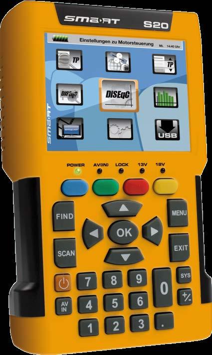
6 User Information 1 User Information 1.1 Use of this Manual This manual is intended for the DVB-S2 Meter smartmeter S20. Please carefully read this user manual before operating the device for the first time. Please note all warnings and notes included in this user manual. Consider this user manual to be an integral part of the product, and store it at a well accessible location. This user manual should also be enclosed when handing over the device to a third party. In case of loss, the current version of the user manual can be downloaded at the support center on our website The software is still being further developed even after your purchase of the device. Thus, it may be possible that certain operation steps do not fully correspond to the user manual. 1.2 Signs, Symbols, Layout Symbol/layout Meaning WARNING Danger due to electric shock with possible severe bodily injury CAUTION Warnung vor einem möglichen Sachschaden NOTE Useful information and hints You are requested to perform an action. 1. Perform these steps in the stated order. 2. List kursiv fett fett & kursiv The various possibilities of settings as well as image captions are stated in Italics. The designations of keys are printed in bold letters. Menu windows and menu items (that often include further hidden menu items or direct settings) are printed in bold & italic letters. 2 Product Description The smartmeter S20 is a handy digital DVB-S2 measuring device for a quick and easy alignment of satellite antennas. If a satellite is found, the smartmeter S20 shows it on the display and emits an audible signal. Signal strength and quality are displayed as numerical values and bar graphs. 6 smartmeter S20
7 Product Description Another measurement value is the forward error correction (FEC0F1 ), the carrier-to-noise ratio (C/N), the bit error rate after Viterbi (VBER), and the Modulation error rate (MER1F2 ). In addition, the picture quality can be revised on the high-resolution 3.5-inch TFTLCD screen. Many satellites are pre-programmed in order to allow a quick antenna adjustment. There is a protective pouch for transport and as a protection. 2.1 Scope of Delivery Please check if the delivery is complete. Included in delivery: DVB-S2 Meter smartmeter S20 12 V plug-in power supply 12 V car adapter cable Quick-F connector Carrying bag User manual If the delivery should be incomplete, contact your specialist dealer or the smart electronic GmbH. 1 FEC = Forward Error Correction: In each data packet there are control bits. FEC 5/6 means, that there are 5 data bits and 1 control bit. The better the ration between data and control bits, the less errors are at the receiver's side. With FEC 3/4 the ratio is better than with FEC 5/6. Possible values are FEC 1/2, 2/3, 3/4, 5/6, 7/8 und 8/9. 2 Modulation error rate = all signal disturbances are summarized to one measurement value. The higher the MER value, the better is the signal quality. smartmeter S20 7

8 Product Description 2.2 Meter Front View No. Description 1 LC-Display Display of the TV picture, the menu and the measured values.. 2 POWER AV IN LED green the meter is on off the meter is turned off Charging: red during charging green the battery is fully charged Lights if the meter is switched to the analog video input. LOCK Lights when a signal is received. 13V Lights if there is a 13 V signal for the polarization control (vertical) 18V Lights if there is a 18 V signal for the polarization control (horizontal) 3 FUNCTION keys Different functions depending on the menu. The functions are displayed at the bottom of the screen. 4 FIND Call of the channel search function. 5 SCAN Start of the automatic channel scan. 6 POWER Switch device on/off. 7 AV IN Switch to the analog video input. 8 Numeric keys Direct entry of numbers. 8 smartmeter S20

 3 Analog video input (Composite Video) 2.2.3 Bottom View No.")
9 Product Description No. 9 Description Cursor cross OK Press to navigate through menus/submenus: Press, to switch between stations, Press, to adjust the volume. Press to confirm your selection / display station list. 10 MENU Display the main menu. 11 EXIT Leave the current menu, cancel operation. 12 SYS TV mode: call of the menu OSD Setting, Menu: volume control. 13 +/- Call of the media player. 14 Pressing this key copies a screenshot to a connected USB disk Top View No. Description 1 Digital satellite signal input 2 Analog audio input (mono) 3 Analog video input (Composite Video) Bottom View No. Description 1 Low-voltage socket (for power plug) 2 Switch for battery (for separating the smartmeter S20 electronics from the rechargeable battery) 3 USB port for external data storage devices The above figures show the smartmeter S20 without the black part covering at the top of the device Rear View At the rear is the battery compartment. Normally, you must not open it. If you suspect that the lithium-polymer battery must be replaced, contact your dealer. 2.3 Guarantee The digital meter smartmeter S20 of smart electronic GmbH comes with a guarantee in accordance with legal requirements as applicable at the time of the purchase. smartmeter S20 9
10 Safety Notes 3 Safety Notes 3.1 Safety of persons Ensure that nobody can be hurt by falling tools or parts of the satellite antenna during the adjustment and installation of the antenna. For your own security use a rope on sloping roofs. 3.2 Appropriate Usage The measuring device smartmeter S20 was developed to measure signals of digital satellite antennas and satellite systems. It is exclusively for this purpose and should only be used for this purpose. Use the equipment only for the purpose, which is described in this manual. Any other usage is rated as not properly and can result in damage or even injury. There will be no liability for damages caused by a non-intended use. 3.3 Hazards from Improper Use CAUTION! Make sure the meter and especially the power plug are always kept dry. Do not expose the meter to temperatures below 0 C. Connect the power plug only to V AC, 50/60 Hz. Charge the meter only with the supplied power plug. During electrical storms, disconnect the meter from the aerial and from the power supply. Do not put heavy objects onto the meter. Avoid mechanical influences that can damage e.g. the LCD display or the housing of the meter. Do not bend or crimp the cables. Do not start to use the meter if you can see signs of damage or if you can hear loose parts inside the device. WARNING! Danger of electrical shock from high voltage Damages on the housing of the power plug or an improperly repaired power plug can expose the user to mains voltage. Do not open the supplied power plug. Have the power plug repaired by qualified personnel only. 10 smartmeter S20
11 Safety Notes Taking the device from cold into warm temperatures can lead to condensation forming inside the device. Do not connect the device instantly. Leave it switched off for a few hours. 3.4 Lithium Polymer Battery The smartmeter S20 is provided with a lithium polymer battery. Please observe the following safety notes for the battery: WARNING WARNING Fire and explosion hazard Any kind of heat (from inside or outside) can trigger uncontrollable chain reactions inside the battery. Do not store or use the battery in temperatures above 40 C. Never connect the two poles (+ and -). Never expose the battery to high temperatures, e.g. close to stoves or cookers or other hot objects. Charge the battery only with the supplied power plug. CAUTION! CAUTION! Risk of injury Damages on and improper use of the battery can lead to fumes leaking from the battery. When inhaled, these fumes can irritate the respiratory tracts. Avoid any damaging of the battery. If fumes leak from the battery, open the window and seek medical advice if you experience health problems that may result from inhaling battery fumes. Damages to other objects Defective batteries can leak and spill battery liquid onto close-by objects. Check the objects affected. Clean or, if necessary, replace the objects affected. smartmeter S20 11
12 Initial Setup 4 Initial Setup 4.1 Charging the Battery Charge the battery completely before you use the meter for the first time. The battery can be charged regardless of whether the meter is switched on or off or whether the battery-switch on the underside of the meter is set to On or Off. An integrated automatic charging system ensures optimum charging of the battery. Switch off the meter, if it is not yet switched off, to ensure that the complete power of the power supply can be used to charge the battery. Basically, the meter is also charged if it is switched on, then the charging period becomes longer. Plug the power plug into a 230-V socket. Connect the low-voltage plug of the power plug to the low-voltage socket on the bottom of the meter. The battery starts charging as soon as you connect the smartmeter S20 to the power plug. When you charge the battery for the first time, charge it for at least 5 hours. The maximum charging time is 12 hours Charge Control Charging is indicated by a continuously moving battery symbol in the display:. The POWER LED lights red.. Completed charging is indicated by a steady battery symbol filled with four bars:. The POWER LED lights green State of Charge The current status of the battery is continuously displayed: If the battery is not adequately charged, the battery charging icon will be displayed in red with 1 or 2 lines (corresponding to the state of charge). You should charge the battery. If the battery is sufficiently charged, the battery charging icon will be displayed in green with 3 or 4 lines. 4.2 Switching the Meter On and Off Switching On 1. Ensure that the battery-switch on the underside of the meter is set to an ON position. 2. Press the POWER key to switch on the meter. The POWER LED lights green. 12 smartmeter S20

13 Initial Setup In case of disconnected power supply, the smartmeter S20 will be turned on, once you put the battery switch from the OFF to the ON position. If the power supply is plugged in, the battery switch will be useless, meaning that the smartmeter S20 can be switched on regardless of the switch position Switching Off Press the POWER key once again to switch off the meter after use. For long operational pauses, please also separate the smartmeter S20 electronics from the battery by setting the battery switch on the underside of the device to the OFF position. 4.3 Entering and Exiting the Menu Press MENU to enter the main menu. The display shows the OSD2F3 main menu. The display shows the main menu window when you switch the smartmeter S20 on and when you re-enter the menu. Press EXIT to exit the menu or to return to the previous menu level. Depending on the submenu you are in, you may have to press the EXIT key several times to return to the main menu. 4.4 Navigating through the Menu Use the colored function keys and the navigation keys to navigate through the menu: Press / the yellow function key to select the menu item to the right or to increase the selected value. Press / the red function key to select the menu item below. Press / the blue function key to select the menu item to the left or to decrease the selected value. Press / the green function key to select the menu item above. Press OK to enter the selected menu item. Activated menu items are highlighted by color. 3 OSD = On Screen Display smartmeter S20 13
14 Aligning the Satellite Dish The function keys may call different functions, dependent on the regarding menu. Instead of changing a value by using the keys und, with many menu items you can also press the OK key, select a new value from the list, and confirm such value by again pressing the OK key. 5 Aligning the Satellite Dish 1. Press MENU. 2. Use the keys / and / to select the menu item TP SEARCH and confirm your selection with OK. 3. Select the desired satellite in the setting field with the keys /. 4. Go to LNB Freq and select the right value for the used LNB. You also can change the LNB frequencies with the blue function key. Possible values for LNB Freq (MHz) Universal ( ) UnicableA ( ) UnicableA (10200) UnicableB ( ) UnicableB (10200) If you use a multifeed antenna, go to DiSEqC1.0 and select the port for the selected satellite. You also can change the DiSEqC1.0 port with the yellow function key. 6. If you can receive signals from more than four satellites select DiSEqC1.13F4 and set the port for the selected satellite. Factory setting is Disable. 7. Go to Transponder and use the keys / to select the transponder, broadcasting the channel, which you want to use for adjusting your antenna. Signal strength and signal quality (of the selected transponder) are displayed on the bottom of the window. Alternatively go to Transponder, press OK, select the corresponding transponder from the list and confirm by pressing OK. 8. Turn the dish until the LOCK LED lights or the bar graph displays signal strength and signal quality. If the LOCK LED lights there is also an acoustic signal In the menu OSD Setting Beeper you can set, whether an acoustic signal should be output (On) or not (Off), if a signal is found. 9. Fixate the Dish in the position with the best signal strength. 4 DiSEqC1.1 supports 16 satellite positions 14 smartmeter S20
, and MER (modulation error rate) are shown. 12.")
15 Menu TP Search 10. Vary the angle of inclination until the bargraph displays even more signal strength and signal quality. 11. Press EXIT, several times to get to the TV mode. In the info window on the bottom of the window signal strength S, signal quality Q, FEC, VBER (bit error rate after Viterbi), and MER (modulation error rate) are shown. 12. Fixate the Dish in the position with the best VBER quality. The VBER value with good reception is 10E-8 (so almost 0). The higher VBER is, the worse is the signal (e. g. antenna wrong aligned). 6 Menu TP Search Select the menu TP Search and press OK. In the menu TP Search a list of the stored satellites is shown. 10 satellites are displayed on each page. To display further satellites use the keys and. 6.1 Renaming a Satellite 1. Select the satellite you d like to rename in the list with the keys and. 2. Press the blue function key (Edit). A screen keyboard opens. 3. Give a new name for the satellite. Use the keys / and / to mark a character and confirm each character with OK. 4. Repeat until you have the desired name. Press the blue function key (Delete) to delete the respectively selected character. Press the yellow function key (CAPS) to switch between upper case and lower case. Press the red function key (Cancel) to discard the changes made so far and to close the window Rename. Press the green function key (OK) to accept the changes made so far and to close the window Rename. 6.2 Adding a Satellite 1. Press the green function key (Add). A screen keyboard opens. 2. Give a name for the new satellite. Use the keys / and / to mark a letter and confirm each letter with OK. 3. Repeat until you have the desired name. Press the blue function key (Delete) to delete the respectively selected character. smartmeter S20 15
16 Menu TP Search Press the yellow function key (CAPS) to switch between upper case and lower case. Press the red function key (Cancel) to discard the changes made so far and to close the window Rename. Press the green function key (OK) to accept the changes made so far and to close the window Rename. 6.3 Deleting a Satellite The transponder list of the new satellite is empty. Create a new transponder as described below (Adding a new Transponder). 1. Select the satellite you d like to delete from the list with the keys and. 2. Press the red function key (Delete). 3. Use the keys / to mark the button Yes and confirm with OK to delete the satellite from the list. Mark the button No and confirm with OK to go back to the menu TP Search, without deleting the satellite. 6.4 Searching for a Transponder Select with the keys and the satellite on which you d like to look for a transponder. Press OK. With the keys and you can know change once more the satellite. Go to LNB Freq and select the right value for the used LNB. The possible values are listed in the section Aligning the Satellite Dish. You also can change the LNB frequencies with the blue function key. If you use a multifeed antenna, go to DiSEqC1.0 and select the port for the selected satellite. You also can change the DiSEqC1.0 port with the yellow function key. If you can receive signals from more than four satellites select DiSEqC1.1 and set the port for the selected satellite. Factory setting is Disable. 6.5 Deleting a Transponder 1. Select in the sub menu TP search with the keys and the satellite on which you d like to delete a transponder and press OK. With the keys and you can know change once more the satellite. 2. Select with the keys and the line Transponder and press OK. 3. Select with the keys and the Transponder you want to delete and press OK. 4. Press the red function key (Del). 16 smartmeter S20
17 Menu TP Search 5. Use the keys / to mark the button Yes and confirm with OK to delete the transponder from the list. Mark the button No and confirm with OK to go back to the menu TP Search, without deleting the transponder. 6.6 Adding a Transponder 1. Select in the sub menu TP search with the keys and the satellite on which you d like to add a transponder and press OK. With the keys and you can know change once more the satellite. 2. Select with the keys and the line Transponder and press OK. 3. Select with the keys and the last position New TP in the list and press OK. The window Add TP opens. Select with the keys and the line Frequency and insert with the numeric keys the frequency (in MHz) of the new transponder. Select with the keys and the line Symbol Rate and insert with the numeric keys the symbol rate (in ks/s) of the new transponder. Select with the keys and the line Polarity and insert with the keys and the polarization of the new transponder. H = horizontal V= vertical 4. Press the green function key (OK) to confirm the new transponder. 6.7 Searching Channels 1. Select in the sub menu TP search the satellite containing the transponder on which you d like to look for receptable channels and press OK. 2. Go to Transponder and select with the keys and from the list the transponder on which you d like to look for receptable channels and press OK. 3. Go to LNB Freq and select the right value for the used LNB. The possible values are listed in the section Aligning the Satellite Dish. You also can change the LNB frequencies with the blue function key. 4. If you use a multifeed antenna, go to DiSEqC1.0 and select the port for the selected satellite. You also can change the DiSEqC1.0 port with the yellow function key. 5. If you can receive signals from more than four satellites select DiSEqC1.1 and set the port for the selected satellite. Factory setting is Disable. 6. Press the green function key to go to the search window: Select Only FTA4F5 to determine if scan should be made only for FTA channels (Yes) or for all channels (No). Select at Scan Channel if you want to perform scan only for TV channels, only for radio channels or for TV + radio channels.. Select at Network Search if you want to search for an individual channel (No) or all channels of a channel network (Yes), e.g. PRO7, SAT1, KABEL1, SIXX. Press OK to start the channel search. 5 FTA = Free To Air = unencrypted channels smartmeter S20 17

18 Menu Satellite Identify Press the red function key to stop the search at any time. Found programs are attached to the rear of the channel list. 6.8 NIT The smartmeter S20 is equipped with NIT. NIT means Network Information Table and is transmitted in the data stream of the satellite. It contains data regarding to transponders and channels, such as frequency, sound carrier or symbol rates. To align a satellite antenna you can also use the NIT display. When a signal is found worthy to receive, the NIT display tells you to which satellite your antenna is actually aligned. Examples: NIT NIT In order that a satellite can be found, the remaining data, especially transponder data and DiSEqC port must be correct. 7 Menu Satellite Identify 1. In TV mode press the MENU key (or navigate to main menu). 2. Select the sub menu Satellite Identify and confirm with OK. 18 smartmeter S20

19 Menu Packet Control 3. Go to LNB Freq and select the right value for the used LNB. The possible values are listed in the section Aligning the Satellite Dish. You also can change the LNB frequencies with the blue function key. 4. If you use a multifeed antenna, go to DiSEqC1.0 and select the port for the selected satellite. You also can change the DiSEqC1.0 port with the yellow function key. 5. If you can receive signals from more than four satellites select DiSEqC1.1 and set the port for the selected satellite. You also can change the DiS- EqC1.1 port with the red function key. Factory setting for DiSEqC1.1 is Disable. You can see on the screen, which satellite is currently received. Also, signal strength and signal quality are displayed. Satellity Identify uses the transponder lists stored in the smartmeter S20. 8 Menu Packet Control In this menu you can display signal strength and signal quality of five consecutive transponders as well as perform a channel search. 8.1 Showing Measurement Values of five Transponders 1. In TV mode press the MENU key (or navigate to main menu). 2. Select with the keys / and / the sub menu Packet Control and confirm with OK. 3. Select at Satellite with the keys and the satellite where you can find the transponders to display. 4. Go to LNB Freq and select the right value for the used LNB. The possible values are listed in the section Aligning the Satellite Dish. You also can change the LNB frequencies with the blue function key. 5. If you use a multifeed antenna, go to DiSEqC1.0 and select the port for the selected satellite. You also can change the DiSEqC1.0 port with the yellow function key. 6. If you can receive signals from more than four satellites select DiSEqC1.1 and set the port for the selected satellite. Factory setting is Disable. You can see on the screen signal strength S and signal quality Q of five consecutive transponders. Press the red function key (Next TPs) to display the values of the next five transponders in the transponder list. smartmeter S20 19
20 Menu DiSEqC Search 8.2 Searching Channels Press the green function key to open the window Single Satellite Search where you can search for channels on one satellite. You also can reach the window Single Satellite Search by pressing of the key SCAN. Select at Satellite with the keys and the satellite on which you want to perform the scan. Select Only FTA5F6 to determine if scan should be made only for FTA channels (Yes) or for all channels (No). Select at Scan Channel if you want to perform scan only for TV channels, only for radio channels or for TV + radio channels.. Select at Network Search if you want to search for an individual channel (No) or all channels of a channel network (Yes), e.g. PRO7, SAT1, KABEL1, SIXX. The item Network Search is only active, if you selected the Scan Mode Preset Scan. Select the scan mode at the menu item Scan Mode: Preset Scan (Standard Scan): considering only the frequencies included in the TP list (of the regarding satellite). Auto Scan (Blind Scan): considering all frequencies, regardless of whether they are included in the TP list or not. Press the green function key to start the channel scan. Press the red function key to stop the search at any time. 9 Menu DiSEqC Search In this menu you can scan the DiSEqC switch. As result of the scan you see on which port which Satellit is received. 1. In TV mode press the MENU key (or navigate to main menu). 2. Select the sub menu DiSEqC Search and confirm with OK. 6 FTA = Free To Air = unencrypted channels 20 smartmeter S20

21 Menu DiSEqC Motor Search The DiSEqC search begins automatically. One after another, all four DiSEqC1.0 ports are scanned. After completing the scan, the screen might look like this: Press the blue function key to select the right frequency for the used LNB. Press the green function key to switch between DiSEqC1.0 und DiSEqC Menu DiSEqC Motor Search This menu is used to set up a motor antenna and its control system. In all menu windows (e. g. moving dish) you see signal strength S and signal quality Q. 1. In TV mode press the MENU key (or navigate to main menu). 2. Select the sub menu DiSEqC Motor Search and confirm with OK. Press the blue function key to turn the satellite dish to the west. Press the yellow function key to turn the satellite dish to the east. Press the green function key to start a channel search for the current transponder (see section 6.7 Searching Channels ). Since you use DiSEqC1.2 or USALS for the antenna control, normally you can ignore the lines DiSEqC1.0 and DiSEqC1.1. There are special cases (e. g. cascading of DiSEqC switches) where additionally to DiSEqC1.2 you need DiSEqC1.1. Press the red function key to set the details for the motor control: Select at Satellite with the keys and the satellite for the following settings should be valid. Select Transponder to set the transponder which should be reference for the antenna position (generally the transponder which broadcasts your favorite channel). Select Motor Type to set the used control technique. Select between DiSEqC1.2 and USALS (depending on the used motor). Depending on your choice, different settings are available. smartmeter S20 21
. Select Save and move the dish with the keys and to the west or the east.")
22 Menu Spectrum 10.1 DiSEqC 1.2 Select Position No & Save to set a position number as which the current satellite (the current antenna position) will be saved. Select Go To X to call a position from which you want start the settings (the value Reference is the zero position). Select Save and move the dish with the keys and to the west or the east. Look for the maximum values of signal strength and signal quality which are shown at the bottom edge of the screen. Then press OK to save the found position. If necessary, repeat these steps for other satellites / transponders. Select Recalculation and press OK to discard all settings and define once more the antenna positions. A query window opens. Confirm the deletion with the green function key (Yes) or cancel it with the red function key (No) USALS Select Local Longitude to enter the longitude of your antenna s position with the numeric keys Select Local Latitude to enter the latitude of your antenna s position with the numeric keys Menu Spectrum In this submenu, you can check the different transponders across the entire spectrum. 1. In TV mode press the MENU key (or navigate to main menu). 2. Select the sub menu Spectrum and confirm with OK. Press the blue function key to switch the polarization between horizontal (H) and vertical (V). Press the green function key to change the sample rate: 4 M: very exact scan, 8 M: middle precision 16 M: less precise ) The more accurate the scan, the longer it takes to capture the entire frequency range. Press the red function key to select the DiSEqC port and thus the satellite. Press the yellow function key to set the 22 khz control voltage for the switch between high band and low band: 22 smartmeter S20

23 Menu Watch Program On Off Auto Permanent on, Permanent off, automatic The permanent settings are required, for example, for certain antenna systems or to avoid interferences. 12 Menu Watch Program To check the TV reception, you can put the smartmeter S20 in the TV mode. In the main menu select the sub menu Watch Program and confirm with OK or press EXIT in the main menu to switch to TV mode. ) After the first switch-on (or after resetting to factory settings), no programs are stored, the channel list is empty. You receive an error message: No Channel! In addition to the live TV picture an infobar appears with the following information: Satellite, current date, current time Position in the current channel list, channel name with video PID, audio PID, PCR PID. Transponder data: frequency / symbol rate / polarization Error correction rate FEC Transmission standard, modulation Bit error rate VBER (bit error rate after error correction) Modulation error rate MER: all signal disturbances are summarized to one measurement value. The higher the MER value, the better is the signal quality. The MER can be worsened by these issues: Noise (C/N), Low frequency hum (50/100 Hz), Inter modulation errors (overridden amplifiers), I/Q modulation errors (phase/amplitude), Signal overlap (DECT phone), Standing waves (maladaptation or unfavorably mounted cables) Signal strength S, signal quality Q Press EXIT to open a toolbar (with four buttons) instead of the infobar. Press the blue function key (Information) to open the infobar. Press the green function key (Full Screen) to close the toolbar and to show only live TV. Press the red function key (Mute) to switch off the TV sound. Press the yellow function key (Audio) to select the audio mode: Use the keys and to select between: Left, Right, Stereo, Mono smartmeter S20 23
24 Menu Watch Program and the keys and to select another language or Dolby AC3 (Dolby Digital) Selecting a Channel When selecting AC3 there is no TV sound. This option is only for verifying such programs / channels. You have several possibilities to select a channel Direct Channel Selection Select the desired channel by using the keys and. With each change of channel, an information window with information on the current channel will be displayed (see above) Channel Selection via Selection Window 1. Press the OK key to display a selection window with all available channels. 2. Select the channel list with the desired channel by using the keys and. You can select between a channel list for all satellites, channel lists for each satellite and you favorite lists. You can create favorites lists only with the channel list editor (see "edit channel list using the editor program", page 28) 3. Select the channel to be displayed by using the keys and and confirm your selection by pressing OK. The channel will be correspondingly switched Channel Selection via Search Function The channel lists can be quite comprehensive; correspondingly, the smartmeter S20 offers the possibility to search for channels in the list: 1. Press the FIND key to open the window Find with an on-screen-keyboard. 2. Select a character by using the keys / and / and respectively confirm by pressing OK to accept such character. 3. As soon as the first selected character has been confirmed by pressing OK, a second window will open, showing all channels starting with this character (in most cases, the first character is a letter). Press EXIT to close the window Find, provided that selection is sufficiently arranged for your purposes. Now, you can select the desired channel in the other window by using the keys and, and confirm by pressing OK. 4. Return to entry of characters (see step 2) to further limit channel selection Sorting the Channel List 1. In TV mode press OK. 2. Press the blue function key (Sort) to open a window for determining sorting criteria. 3. Select Name(A-Z) to sort the channel list in ascending alphabetical order or Select Name(Z-A) to sort the channel list in descending alphabetical order or 24 smartmeter S20
 to go back to the TV mode. 12.3 Switching Between TV Channel List and Radio Channel List 1. In TV or radio mode press OK. 2.")
25 Menu Settings Select Free/Scramble to first list all free channels and then all encrypted channels in the channel list. 4. Press OK to confirm. 5. Press the yellow function key (Play) to go back to the TV mode Switching Between TV Channel List and Radio Channel List 1. In TV or radio mode press OK. 2. Press the green function key (TV/Radio) to switch between TV channel list and radio channel list (or vice versa). 3. Press the yellow function key (Play) to go back to TV mode or radio mode Deleting a Channel from the Channel List 1. In TV mode press OK. 2. Select with the keys and the channel list including the channel you want to delete. If necessary, switch between TV channel list and radio channel list. 3. Select with the keys and the the channel you want to delete. 4. Press the red function key (Delete) to delete the channel. A safety query opens: Press the green function key (Yes) to complete the deletion. Press the red function key (No) to cancel the deletion and go back to the channel list. 5. Press the yellow function key (Play) to go back to TV mode. 13 Menu Settings 1. In TV mode press the MENU key (or navigate to main menu). 2. Select the sub menu Settings and confirm with OK. The window OSD Setting opens Hiding the OSD Select OSD Timeout, to set with the keys and the number of seconds when the OSD should be hided. You can select values between 1 and 10 seconds. Factory setting is 3s Switching off the Screen Select Back Light Off to set with the keys and the number of minutes when the screen should be switched off. You can select values between Off and 30 Minutes. Factory setting is 5 Minutes. smartmeter S20 25
26 Menu PC Update 13.3 Setting Display Brightness Select Back Light Level to set with the keys and the display brightness. You can select values between 1 (dark) and 5 (light). Factory setting is Selecting Energy Unit Select Energy Uni to set with the keys and in which unit you want to show the voltage measures during spectrum analysis. You can select between dbm and dbµv. Factory setting is dbµv Setting Volume Level Select Value to set with the keys and the level of the TV sound plus the beeper sound level when a signal is found. You can select values between 10 and 100. Factory setting is Switching On/Off the Beeper Select Beeper to set with the keys and whether there should be a beeper sound when a satellite signal is found (On) or not (Off). Factory setting is On Activating the Automatic Standby Function Select Auto Standby to switch on or switch off the automatic standby function, and if on after which time the meter should go to standby mode, using the the keys and. You can select values between Off und 3 Hours. Factory setting is 3 Hours Selecting the OSD Language Select Language to set with the keys and the OSD language. Factory setting is Deutsch Restoring Factory Settings 1. Select Factory Setting and press OK to restore factory settings. 2. Press the green function key (Yes) to complete the restore or press the red function key (No) to cancel the restore and go back to the menu window. 14 Menu PC Update A factory reset will erase all channels in your channel list! The sub menu PC Update is mainly intended to update the operating software via the USB port. 26 smartmeter S20
27 Menu PC Update 1. In TV mode press the MENU key (or navigate to main menu). 2. Select the sub menu PC Update and confirm with OK. The window Upgrade by USB opens Showing the Software Version Press the blue function key (Version) to display software and hardware version of your smartmeter S Performing a Software Upgrade CAUTION! Make absolutely sure that the smartmeter S20 is supplied during the upgrade. During the update supply the smartmeter S20 with electrical power by power supply unit. 1. Look for the current software release packed as a zip archive in the support area of 2. Unpack it and save the file with the extension *.abs on your USB disk. Tips and hints to extract and update can be found in the support area of 3. Connect the USB disk to the smartmeter S Select the line Upgrade File. 5. Select the new software file (*. abs) (must be in the root directory of the connected USB disk!). 6. Select the line Upgrade Mode. 7. Make sure that the Upgrade Mode is All Code. If necessary, you must change the value by pressing the keys and. With All Code the software, the current channel list and the "factory" channel list (default setting is empty) are newly loaded into the smartmeter S Use the keys and to select the button Start and press OK or press the green function key (Start) to start the upgrade process. You will see a security warning asking if you really want to burn the flash memory: Press the green function key (Yes) to start the Upgrade. After it is completed, the meter will be restarted. Press the red function key (No) to cancel the Upgrade and go back to the window PC Update. smartmeter S20 27
28 Menu PC Update Never switch off the smartmeter during the upgrade process. CAUTION! 14.3 Editing the Channel List You can save the channel list of the smartmeter S20 on a USB disk, edit it in conjunction with the appropriate editor program6f7 and then load it from USB disk. Also, you can create a "fixed" channel list that is preserved even at a factory reset Saving the Channel List on a USB disk 1. Select - with a connected USB disk - in the window Upgrade By USB with the keys and the line Upgrade Mode and then use the keys and to select the value Dump. The file name (ending in ".abs") appears in the line Upgrade File. In this file these items are stored: the operation software, the current channel list ("your channel list") and the "factory" channel list (default setting is empty).^ 2. Select with the keys and the button Start and press OK or press the green function key (Start) to start the saving Editing the Channel List with the Editor Program 1. Download from (Support / Zubehör / smartmeter S20 / smartmeter S20 Downloads) the compressed file Kanallisten-Editor.zip and save it on your PC. Kanallisten-Editor.zip contains these files: Kanallisten-Editor.exe script.ini User_Manual.pdf (user manual in English) BA_Kanallisten-Editor_S1_S20.pdf (user manual in German) 2. Unzip the zip file into a directory of your choice. 3. Start the program Kanallisten-Editor_S1.exe. With the channel list editor, you can load both your channel list (User Database) or the work list (Default Database) which you have previously saved on your USB disk, move channels in the channel list, edit channel parameters, create up to 32 favorites lists and 7 Kanallisten-Editor.zip, available free of charge in the support area (German) of under Zubehör / Antenne / smartmeter S20 / smartmeter S20 Downloads. 28 smartmeter S20
29 Saving a Screenshot save the edited list as an own channel list (User Database) as well as a new factory list (Default Database) and then load it into your smartmeter S20 (as User Database or Default Database). CAUTION! When delivered, the "factory list" is empty, i.e. there are no channels available Loading the Channel List from USB Loading the Own Channel List from USB 1. Select - with a connected USB disk - in the window Upgrade By USB with the keys and the line Upgrade File. 2. Select with the keys and the channel list file (*.abs), containing the own channel list you want to transfer to your smartmeter S20 (must be located in the root directory of the USB disk!). 3. Select with the keys and the line Upgrade Mode and select with the keys and the value User Database. 4. Select with the keys and the line Start and press OK or press the green function key (Start) to start the loading Loading the Factory Channel List from USB 1. Select - with a connected USB disk - in the window Upgrade By USB with the keys and the line Upgrade File. 2. Select with the keys and the channel list file (*.abs), containing the factory channel list you want to transfer to your smartmeter S20 (must be located in the root directory of the USB disk!). 3. Select with the keys and the line Upgrade Mode and select with the keys and the value Default Database. 4. Select with the keys and the line Start and press OK or press the green function key (Start) to start the loading. 15 Saving a Screenshot 15.1 Capturing a Screenshot If a USB data storage device is connected to the meter, you can save a screenshot of the display to the data storage device (e.g. to document measuring values). Press the (14) key. A screenshot of the display is saved to the USB data storage device in a bmp file Displaying a Screenshot 1. In TV mode press the MENU key (or navigate to main menu). 2. Select the sub menu PC Update and confirm with OK. The window Upgrade by USB opens. smartmeter S20 29
30 Operation in a Unicable System 3. Press the yellow function key (Snapshot). 4. Press to select the connected data storage, and confirm by pressing OK. The present directories and files will be displayed. 5. Select the image to be displayed (on the right side of the screen you see a preview image). 6. Press OK to display the image in full screen mode. By default, the playback mode for images is slide show mode. You can stop the slide show mode by pressing the keys or (go backward or go forward) Renaming an Image 1. Press during preview of an image the red function key. A screen keyboard opens. 2. Press first (if necessary for several times) the blue function key (delete) to delete the last character. Enter a new name for the image by highlighting the characters on the screen keyboard using the keys / and / and confirm them with OK. 3. Repeat this step, until the desired name is completed. Press the green function key (OK) to confirm the inserted name and go back to the list of images. Press the red function key (Cancel) to go back to the list of images, without renaming the image. Press the yellow function key (CAPS) to switch between upper case and lower case Rotating an Image "Rotate an Image" does not change the respective files, but only change the current view! 1. Select the image to be rotated. 2. Press OK to display the image in full screen mode. 3. Press the keys and once or several times to rotate the image clockwise/counterclockwise by 90 degrees. 16 Operation in a Unicable System 16.1 About Unicable The smartmeter S20 allows for changing the receiving mode to the unicable standard. This makes it possible - depending on the antenna type - to connect up to eight independent receivers to only one main line. For this, an own IF channel and a corresponding frequency should be set for each receiver via the settings menu. Allocation of channels and frequencies depends on the used LNBs and/or multi-switches. 30 smartmeter S20
31 Operation in a Unicable System The data sheet and the technical documentation of your LNB and/or multi-switch include an allocation table similar to the following table Allocation of IF channels and frequencies Receiver IF channel Exemp. frequency (MHz) Frequency (MHz) Receiver Receiver Receiver Receiver Receiver Receiver Receiver Receiver Enter the frequencies of your receiving system into the last column of the table so that all relevant information is quickly available. Rule of thumb: highest frequency shortest cable path Installation 1. Select the menu item TP Search and press OK. 2. Select with the keys and a satellite and press OK. 3. Select with the keys / the line LNB Freq. 4. Select with the keys and the right value for the used Unicable LNB (according to the LNB specs). 5. Select with the keys / the line DiSEqC1.0 and switch off the DiSEqC port use with the keys and. Ensure that also DiSEqC1.1 is disabled. 6. Select with the keys / the line IF Channel and set with the keys and the IF channel according to the specs of the unicable system. 7. Select with the keys / the line Centre Freq and set with the keys and the frequency according to the specs of the unicable system. The assignment of channels and frequencies depends on the LNB or multiswitch manufacturer. You can also input the Centre Frequency (if you selected a Unicable LNB) by pressing the yellow function key. smartmeter S20 31
32 Cleaning the Meter 17 Cleaning the Meter WARNING! CAUTION! Danger of electric shock during cleaning: Before you start cleaning the meter, disconnect the meter from the power plug. Unplug the power plug from the socket. Never use a wet wipe to clean the meter or power plug. Make sure that meter and power plug are always kept dry. Risk of damages to the meter during cleaning: Always use solvent-free cleaning agents (no benzine, no thinner). Use a soft lint-free wipe to clean the housing and display of the meter. If the meter is very dirty, you may use mild, solvent-free soapsuds or spirit for cleaning. You may use compressed air (max. 2 bar) to clear the keypad of dirt. Do not use any solvents for cleaning. 18 Transporting and Storing the Meter If you want to transport the meter or if you intend to stop using the meter, handle the device as follows: 1. Disconnect the meter and all connected devices from the power supply. 2. Remove the aerial cable from the device. 3. Remove all other cables connected to the meter. 4. Put the meter, the cables and the user manual into the original packing. 5. Store the meter and the accessories in a dry and dust-free place. 6. Make sure that the meter is protected from frost. 19 Troubleshooting Fault phenomenon Probable reasons Solutions Device does not react. The battery is empty. Charge the battery. Bad picture, block defect The antenna is not adjusted to the satellite. The LNB is defect Adjust the antenna. Replace the LNB. No or only fait signal. Please check all cable connections. Adjust the antenna. 32 smartmeter S20


33 Disposal Fault phenomenon Probable reasons Solutions No picture, no sound. Display/ Sounds turned off Turn on the display by pushing the F1 button. Turn on the sound by pushing the F2 or button. If the troubleshooting suggestions do not help to correct a malfunction, please contact your specialist dealer. You can find an FAQ-list with updated troubleshooting suggestions in the support section on our website at 20 Disposal CAUTION! Do not dispose of the meter or battery in your normal household waste. Ask your municipal authorities about how to dispose of the device in an eco-friendly and proper manner. Take spent batteries to an official collection point. The WEEE7F8 symbol on the product or the product packing indicates that this is an electrical or electronic device. Thus, you will contribute to protecting the environment and people's health. Material recycling helps to reduce the consumption of raw materials. You can help to preserve the environment we live in. 21 Specifications 21.1 General 3,5" TFT-LCD, 720 x 576 pixel Physical separation of meter and battery (on-off-switch) 8 The WEEE symbol stands for the Waste Electrical and Electronic Equipment Directive (2002/96/EC). This Directive was introduced to reduce the ever growing quantity of electronic waste from spent electrical and electronic devices. The aim is to avoid and reduce growing quantities of electronic waste and to promote eco-friendly disposal of such waste through extended manufacturer responsibilities. smartmeter S20 33
DVB-S2/-C/-T2(H.264) Meter. smartmeter S30. User Manual. Version: English
 Meter. smartmeter S30. User Manual. Version: English") DVB-S2/-C/-T2(H.264) Meter smartmeter S30 User Manual Version: 24.04.2017 - English User Information 2 smartmeter S30 User Information Preface Dear Customer, Thank you for purchasing the digital DVB-S/C/T
DVB-S2/-C/-T2(H.264) Meter smartmeter S30 User Manual Version: 24.04.2017 - English User Information 2 smartmeter S30 User Information Preface Dear Customer, Thank you for purchasing the digital DVB-S/C/T
Digital Satellite- Meter. Manual
 Digital Satellite- Meter Manual Version: 15.06.2010 Preface Preface Dear Customer, Thank you for purchasing this digital satellite meter smartmeter S10. Before operating this digital satellite meter, please
GENERAL INFORMATION INSTALLATION MENU INFORMATION. Main Features For your Safety Unpacking General Operation RCU Rear Panel.
 GENERAL INFORMATION 3 Main Features For your Safety Unpacking General Operation RCU Rear Panel 3 4 7 7 8 9 INSTALLATION 10 MENU INFORMATION Main Menu 1. Installation 1.1 Satellite list 1.2 Dish Setting
SATELLITE FINDER SK-3200 USER MANUAL
 SATELLITE FINDER SK-3200 USER MANUAL CONTENTS 1. GUIDE...1 1.1 IMPORTANT SAFETY INSTRUCTIONS... 1 1.2 UNPACKING...1 1.3 PRODUCT OVERVIEW & ILLUSTRATION... 2 2. OUTLINE...4 3. THE MENU OSD INSTRUCTION...5
Satellite locator WS-6933
 R Satellite locator WS-6933 User's Manual English CONTENTS 1. GUIDE...2 1.1 IMPORTANT SAFETY INSTRUCTIONS...2 1.2 UNPACKING...2 1.3 PRODUCT OVERVIEW&ILLUSTRATION...3 2. OUTLINE...4 3. THE MENU OSD INSTRUCTION...5
USER MANUAL. 27 Full HD Widescreen LED Monitor L27ADS
 USER MANUAL 27 Full HD Widescreen LED Monitor L27ADS TABLE OF CONTENTS 1 Getting Started 2 Control Panel/ Back Panel 3 On Screen Display 4 Technical Specs 5 Care & Maintenance 6 Troubleshooting 7 Safety
STM 26 HD. DVB-S2+T2/C Compact meter User Manual. Ref R13. CAHORS Digital CS Cahors Cedex 9 FRANCE
 STM 26 HD DVB-S2+T2/C Compact meter User Manual Ref 0145225R13 Preface USER MANUAL Please read this manual carefully before using your Digital Sat meter for the first time. This operating manual will help
English CONTENTS 1. GUIDE OUTLINE THE MENU OSD INSTRUCTION TECHNICAL SPECIFICATION...17
 USER S MANUAL English CONTENTS 1. GUIDE...2 1.1 IMPORTANT SAFETY INSTRUCTIONS...2 1.2 UNPACKING...2 1.3 PRODUCT OVERVIEW& ILLUSTRATION...3 1.4 INSTALLATION OF METER...4 2. OUTLINE...5 3. THE MENU OSD INSTRUCTION...6
ASF 2050 COMBO USER MANUAL
 ASF 2050 COMBO USER ASF 2050 COMBO USER 1. BUTTONS AND INDICATORS... 2 2. BASIC FUNCTIONS.... 4 2.1 Satellite... 5 2.2Terrestrial... 24 2.3 Cable... 33 2.4 Saving... 41 2.5 System Setting... 42 2.6 USB
OWNER'S MANUAL MODEL: DTV-2000 STANDBY/ON
 OWNER'S MANUAL MODEL: DTV-2000 STANDBY/ON CH+ CH- TABLE OF CONTENTS SAFETY PRECAUTIONS IMPORTANT SAFETY INSTRUCTIONS and FEATURES ACCESSORIES and LOADING BATTERIES REMOTE CONTROL UNIT FRONT PANEL and REAR
USER MANUAL. 27" 2K QHD LED Monitor L27HAS2K
 USER MANUAL 27" 2K QHD LED Monitor L27HAS2K TABLE OF CONTENTS 1 Getting Started 2 Control Panel/ Back Panel 3 On Screen Display 4 Technical Specs 5 Troubleshooting 6 Safety Info & FCC warning 1 GETTING
Xsarius Satmeter Pro. Manual
 Xsarius Satmeter Pro Manual 1 2 Directory of content Introduction Directory of content 3 Introduction 3 Satmeter Pro 02 Frontpanel & buttons 6 Xsarius provides high quality products that enable you to
USER MANUAL. 27 Full HD Widescreen LED Monitor L270E
 USER MANUAL 27 Full HD Widescreen LED Monitor L270E TABLE OF CONTENTS 1 Getting Started 2 Control Panel/ Back Panel 3 On Screen Display 4 Technical Specs 5 Care & Maintenance 6 Troubleshooting 7 Safety
SATFINDER4 INTRODUCTION USER GUIDE AND CERTIFICATE OF GUARANTEE
 SATFINDER4 INTRODUCTION USER GUIDE AND CERTIFICATE OF GUARANTEE CONTENTS : General Safety...... 3 Basic Properties.... 4 Front Panel Keys... 5 Back Panel Details 5 Charger Adapters.. 6 Utilization of Satfinder4......
CONTENTS 8 ACCESSORIES 13 9 TROUBLE SHOOTING AND ADVICE SPECIFICATIONS BATTERY USAGE CAUTION 13
 CONTENTS 1 PREFACE 2 2 SAFETY PRECAUTIONS 2 3 FRONT & BACK VIEW, REAR CONNECTION OF LCD 3 4 TV INSTALLATION DRAWINGS 4 4.1 ANTENNA CONNECTION 4 4.2 AV1 INPUT CONNECTION 4 4.3 AV2 INPUT CONNECTION 4 4.4
Instructions for use. UFS 810 English IMPORTANT READ CAREFULLY BEFORE USE
 Instructions for use UFS 810 English IMPORTANT READ CAREFULLY BEFORE USE List of Contents 1 About these instructions...4 1.1 Contents...4 1.2 Markings...4 1.2.1 Pre-requirements for certain functions...4
USER MANUAL. 28" 4K Ultra HD Monitor L28TN4K
 USER MANUAL 28" 4K Ultra HD Monitor L28TN4K TABLE OF CONTENTS 1 Getting Started 2 Control Panel/ Back Panel 3 On Screen Display 4 Technical Specs 5 Care & Maintenance 6 Troubleshooting 7 Safety Info &
USER MANUAL Full HD Widescreen LED Monitor L236VA
 USER MANUAL 23.6 Full HD Widescreen LED Monitor L236VA TABLE OF CONTENTS 1 Getting Started 2 Control Panel/ Back Panel 3 On Screen Display 4 Technical Specs 5 Care & Maintenance 6 Troubleshooting 7 Safety
USER MANUAL Full HD Widescreen LED Monitor L215ADS
 USER MANUAL 21.5 Full HD Widescreen LED Monitor L215ADS TABLE OF CONTENTS 1 Getting Started 2 Control Panel/ Back Panel 3 On Screen Display 4 Technical Specs 5 Care & Maintenance 6 Troubleshooting 7 Safety
USER MANUAL Full HD Widescreen LED Monitor L215IPS
 USER MANUAL 21.5 Full HD Widescreen LED Monitor L215IPS TABLE OF CONTENTS 1 Getting Started 2 Control Panel/ Back Panel 3 On Screen Display 4 Technical Specs 5 Care & Maintenance 6 Troubleshooting 7 Safety
FV400 DIGITAL TV RECEIVER WITH MODULATOR INSTRUCTION MANUAL
 FV400 DIGITAL TV RECEIVER WITH MODULATOR INSTRUCTION MANUAL Please read this instruction manual carefully before using your receiver Table of Contents Introduction-----------------------------------------------------------------------------
User Manual High Definition Digital Set Top Box DVBT9070 Please read this User Manual carefully to ensure proper use of this product and keep this man
 User Manual High Definition Digital Set Top Box DVBT9070 Please read this User Manual carefully to ensure proper use of this product and keep this manual for future reference. Important Safety Instructions
STM 17 HD. DVB-S2+T2/C Compact Meter. User Manual. Ref R13. CAHORS Digital CS Cahors Cedex 9 FRANCE.
 STM 17 HD DVB-S2+T2/C Compact Meter User Manual Ref 0145131R13 DVB COMBO METER 1. Main Features... 2 2. Buttons and Indicators... 3 3. How to measure... 4 4. Home menu... 5 5. Satellite... 5 5.1 Satellite
English SAFETY PRECAUTION DO NOT INSTALL THE RECEIVER: PAG. 2
 U4127 SAFETY PRECAUTION The lightning fl ash with arrowhead symbol, within an equilateral triangle, is intended to alert the user to dangerous voltage and to prevent from a risk of electric shock. Warning:
USER MANUAL. 22" Class Slim HD Widescreen Monitor L215DS
 USER MANUAL 22" Class Slim HD Widescreen Monitor L215DS TABLE OF CONTENTS 1 Getting Started Package Includes Installation 2 Control Panel / Back Panel Control Panel Back Panel 3 On Screen Display 4 Technical
S7030PVR User Manual
 S7030PVR User Manual Important Safety Instructions 1) Do not use this apparatus near water. 2) Clean only with dry cloth. 3) Do not block any ventilation openings, install in accordance with the instructions.
English SAFETY PRECAUTION DO NOT INSTALL THE RECEIVER: PAG. 2
 U4109 SAFETY PRECAUTION The lightning fl ash with arrowhead symbol, within an equilateral triangle, is intended to alert the user to dangerous voltage and to prevent from a risk of electric shock. Warning:
PCM-1210 DVB COMBO METER User`s Manual
 PCM-1210 DVB COMBO METER User`s Manual 1. Main Features... 1 2. Buttons and Indicators... 2 3. How to measure... 3 4. Home menu... 4 5. Satellite... 4 5.1 Satellite Measure... 4 5.2 LNB Setting... 5 5.3
ATLANTA ASF 2033HD+ DVB-S/S2 METER. User`s Manual
 ATLANTA ASF 2033HD+ DVB-S/S2 METER User`s Manual Buttons and Indicators... 2 How to measure... 3 Main menu... 4 LNB Setting... 4 Edit Satellite... 6 Spectrum Chart... 7 Constellation... 9 Angle Calculation...
GDB9 INSTRUCTION MANUAL DIGITAL TERRESTRIAL RECEIVER
 GDB9 INSTRUCTION MANUAL DIGITAL TERRESTRIAL RECEIVER Goodmans Support: www.goodmans.co.uk/support Please read these instructions before use and keep for future reference IMPORTANT SAFETY INSTRUCTIONS Thank
PL2410W LCD Monitor USER'S GUIDE.
 PL2410W LCD Monitor USER'S GUIDE www.planar.com Content Operation Instructions...1 Safety Precautions...2 First Setup...3 Front View of the Product...4 Rear View of the Product...5 Quick Installation...6
Quick Start Digital Satellite Receiver
 Quick Start Digital Satellite Receiver Support of SD (MPEG2), DVB-S system Standard resolution video output - SCART Compatible with Diseqc 1.0, 1.1, 1.2, and USALS Electronic Program Guide - EPG Multilingual
PLL2210MW LED Monitor
 PLL2210MW LED Monitor USER'S GUIDE www.planar.com Content Operation Instructions...1 Safety Precautions...2 First Setup...3 Front View of the Product...4 Rear View of the Product...5 Quick Installation...6
SZU OPERATING INSTRUCTIONS SAT NAVI
 SZU 21-00 O P ER ATI N G I N S T R U C T I O N S SAT NAVI Operation Instructions SZU 21-00 Safety Notes Turn off the receiver or any used power supply before installing, to avoid short-circuit. Installation
SYMBOLS USED ON THE RECEIVER... 3 SAFETY INSTRUCTIONS... 4 I.GENERAL INFORMATION...
 Table of Contents SYMBOLS USED ON THE RECEIVER... 3 SAFETY INSTRUCTIONS... 4 I.GENERAL INFORMATION... 5 1. Preface... 5 2. Main Features... 5 3. General Operation of the Receiver... 6 4. Front Panel...
NMS ETA TM Stereo Advanced Digital TV Set-top Box
 Digital TV HD Set-top Box STB2-T2 NMS ETA TM Stereo Advanced Digital TV Set-top Box User Guide CONTENTS Safety Information... 3 Introduction... 4 Set-top Box Front Panel... 4 Set-top Box Back Panel...
Be sure to run the vehicle engine while using this unit to avoid battery exhaustion.
 CAUTION: TO REDUCE THE RISK OF ELECTRIC SHOCK DO NOT REMOVE COVER (OR BACK) NO USER-SERVICEABLE PARTS INSIDE REFER SERVICING TO QUALIFIED SERVICE PERSONNE; Please Read all of these instructions regarding
English SAFETY PRECAUTION DO NOT INSTALL THE RECEIVER: PAG. 2
 U4125 SAFETY PRECAUTION The lightning fl ash with arrowhead symbol, within an equilateral triangle, is intended to alert the user to dangerous voltage and to prevent from a risk of electric shock. Warning:
Owner s Manual. Sat-Meter MSK 15. Order No.:
 Owner s Manual Sat-Meter MSK 15 Order No.: 217 100 13 Thank you for choosing our latest and most innovative satellite meter. It has been designed and manufactured to a very high standard and offers a UNIQUE
SAFETY PRECAUTION ENGLISH PAG. 2. rev 1.2. dangerous voltage and to prevent only. operating and maintenance from a risk of electric shock.
 MAX S93+ SAFETY PRECAUTION The lightning fl ash with arrowhead WARNING: To reduce the risk of The exclamation point within an symbol, within an equilateral triangle, electric shock, don t open the cabinet.
DIGITAL SET TOP BOX STB 7017 INSTRUCTION MANUAL
 DIGITAL SET TOP BOX STB7017 INSTRUCTION MANUAL STB 7017 CHANNEL After Sales Support Now you have purchased a Tevion product you can rest assured in the knowledge that as well as your 3 year parts and labour
Throughout the whole user manual, pay special attention to the following marks that
 Notice Warnings, Cautions and Notes Throughout the whole user manual, pay special attention to the following marks that indicate hazardous situations. Warning ** Indicates a hazardous situation which could
User Manual. High Definition Digital Set Top Box HDSTB250
 User Manual High Definition Digital Set Top Box HDSTB250 CHANNEL HDSTB250 Please read this User Manual carefully to ensure proper use of this product and keep this manual for future reference. Important
PLL1920M LED LCD Monitor
 PLL1920M LED LCD Monitor USER'S GUIDE www.planar.com Content Operation Instructions...1 Safety Precautions...2 First Setup...3 Front View of the Product...4 Rear View of the Product...5 Installation...6
User manual FT-8100 HD. English
 User manual FT-8100 HD English WARNING!!! On the USB Memory Function for FT-8100 HD model, user can make recording or playing function using by external USB devices such as USB Flash Memory Disk or external
Front and Rear Panel Remote Control Connecting to a Television...4. Connecting to an Audio System...5
 Table of Contents Front and Rear Panel... 1 Remote Control...... 2 Connecting to a Television...4 Connecting to an Audio System...5 Connecting to a DVD Recorder or VCR... 6 First Time Installation... 7
DIGITAL SATELLITE METER
 DIGITAL SATELLITE METER THE PROFESSIONAL EQUIPMENT DIGITAL SATELLITE METER THE PROFESSIONAL EQUIPMENT USER S MANUAL Product Description 1.Guide 2. Menu 1.1 Face Panel & Button 1.2 Power On/Off 1.3Power
Model:P19LCD. 16:10 DIGITAL LCD-TV-Monitor 19 LCD TELEVISION OPERATING MANUAL.
 Model:P19LCD 16:10 DIGITAL LCD-TV-Monitor 19 LCD TELEVISION OPERATING MANUAL www.pyleaudio.com CONTENTS 1. PREFACE........... 2. SAFETY PRECAUTIONS... 3. FRONT, BACK, CONNECTIONS OF LCD...... 4. TV INSTALLATION
Alpha Plus. User Guide
 Alpha Plus User Guide Contents Contents i 1 Introduction 1 1.1 Features.............................. 1 1.2 Accessories............................ 2 1.3 The Remote Control....................... 3 1.4
Converts any TV to Digital. MFR-300 User Guide
 Converts any TV to Digital MFR-300 User Guide Introduction Thank you for choosing this TVonics Freeview box. Record the serial number in the space provided below (the serial number can be found on the
SAFETY PRECAUTION ENGLISH DO NOT INSTALL THE RECEIVER: PAG. 2
 MAX S92+ HDMI SAFETY PRECAUTION The lightning fl ash with arrowhead symbol, within an equilateral triangle, is intended to alert the user to dangerous voltage and to prevent from a risk of electric shock.
User s Manual Digital Satellite Receiver
 A_ENG_110944 User s Manual Digital Satellite Receiver Please read the entire manual thoroughly and retain it for future reference. ENG - 1 General Safety Warning CAUTION RISK OF ELECTRIC SHOCK DO NOT OPEN
Contents. Safety instructions Reference 1.1 Genareal Features Delivery... 04
 HD 580 user manual Contents Safety instructions... 03 1. Reference 1.1 Genareal Features... 04 1.2 Delivery... 04 2. Names and key assignment 2.1 Front view... 05 2.2 Rear view... 05 2.3 Remote Control...
English CONTENTS 1. GUIDE OUTLINE THE MENU OSD INSTRUCTION TECHNICAL SPECIFICATION TROUBLE SHOOTING...
 English CONTENTS 1. GUIDE...2 1.1 IMPORTANT SAFETY INSTRUCTIONS...2 1.2 UNPACKING...2 1.3 PRODUCT OVERVIEW& ILLUSTRATION...3 1.4 INSTALLATION OF METER...4 2. OUTLINE...5 3. THE MENU OSD INSTRUCTION...6
DH551C/DH550C/DL550C Double Sided Display User Manual
 DH551C/DH550C/DL550C Double Sided Display User Manual Disclaimer BenQ Corporation makes no representations or warranties, either expressed or implied, with respect to the contents of this document. BenQ
Safety Precautions and Maintenance
 Safety Precautions and Maintenance 1. Unplug the monitor before cleaning it with a slightly damp cloth. 2. Wiping the screen with a dry cloth is recommendable, and only during the power has been switched
1. GUIDE Important Safety Instructions Unpacking PRODUCT OVERVIEW&ILLUSTRATION INSTALLATION OFMETER
 1. GUIDE... 3 1.1 Important Safety Instructions... 3 1.2 Unpacking... 3 1.3 PRODUCT OVERVIEW&ILLUSTRATION... 4 1.4 INSTALLATION OFMETER... 6 2. OUTLINE... 6 3. THE MENU OSD INSTRUCTION... 7 3.1 DVB S2...
Table of contents 1 / 20
 Table of contents 1 GUIDE...3 1.1 Important Safety Instructions...3 1.2 Unpacking...3 1.3 PRODUCT OVERVIEW & ILLUSTRATION...4 1.4 INSTALLATION OF METER...5 2 OUTLINE...6 3. THE MENU OSD INSTRUCTION...6
User s Manual. Full HD Digital Satellite Receiver. v1310. Please read this User s Manual carefully before installing the receiver.
 User s Manual Full HD Digital Satellite Receiver v1310 Please read this User s Manual carefully before installing the receiver. 2 CONTENTS 1 Introduction 4 1.1 Features 4 1.2 Accessories 4 1.3 The Remote
CAUTION RISK OF ELECTRIC SHOCK NO NOT OPEN
 Evolution Digital HD Set-Top Box Important Safety Instructions 1. Read these instructions. 2. Keep these instructions. 3. Heed all warnings. 4. Follow all instructions. 5. Do not use this apparatus near
MAX T200 HD QUICK INSTALLATION GUIDE
 MAX T200 HD QUICK INSTALLATION GUIDE MAX T200 HD QUICK INSTALLATION GUIDE CONTENT receiver BATTERIES x 2 REMOTE CONTROL Quick installation guide Quick Installation Guide The lightning flash with arrowhead
AVE HOME FAGOR CVBS TO DVB-T ENCODER MODULATOR. Fagor Electr6nica
 AVE HOME CVBS TO DVB-T ENCODER MODULATOR FAGOR Fagor Electr6nica TABLE OF CONTENTS 1. SPECIFICATIONS... 12 1.1 Product Overview... 12 1.2 Appearance and Description... 12 1.3 Diagram... 13 1.4 Characteristics...
Table of Contents. Table of Contents. Safety Warning General Information. Installing Equipment Channel List Guide Menu Guide Main Page
 TABLE OF CONTENTS Table of Contents Table of Contents Safety Warning General Information Package Contents & Features Front Panel Rear Panel Remote Control Unit (RCU) Programing the Remote Control Installing
SATFINDER 3 HD SLIM USER GUIDE
 SATFINDER 3 HD SLIM USER GUIDE INDEX General Safety..... 3 Key Features..... 4 Panel Keypads... 5 Accesory.. 6 Satellite Search...... 7 Spectrum..... 8 Cross Polarisation... 9 Packet TP Levels.... 9 Multi
User Manual of digital Set Top Box PAT1 02
 User Manual of digital Set Top Box PAT1 02 Please read this User Manual carefully to ensure proper use of this product and keep this manual for future reference. Important Safety Instructions 1) Read these
DC162 Digital Visualizer. User Manual. English - 1
 DC162 Digital Visualizer User Manual English - 1 Table of Contents CHAPTER 1 PRECAUTIONS... 5 CHAPTER 2 PACKAGE CONTENT... 7 CHAPTER 3 PRODUCT OVERVIEW... 8 3.1 PRODUCT INTRODUCTION... 8 3.2 I/O CONNECTION...
English CONTENTS 1. GUIDE OUTLINE THE MENU OSD INSTRUCTION TECHNICAL SPECIFICATION TROUBLE SHOOTING...
 USER S MANUAL English CONTENTS 1. GUIDE...2 1.1 IMPORTANT SAFETY INSTRUCTIONS...2 1.2 UNPACKING...2 1.3 PRODUCT OVERVIEW& ILLUSTRATION...3 1.4 INSTALLATION OF METER...4 2. OUTLINE...5 3. THE MENU OSD INSTRUCTION...6
User s Guide. Digital Satellite Receiver
 User s Guide Digital Satellite Receiver Before Getting Started Information contained in this manual is subject to change without notice. No part of this publication may be copied, reproduced, or translated
PLL2710W LED LCD Monitor
 PLL2710W LED LCD Monitor USER'S GUIDE www.planar.com Content Operation Instructions...1 Safety Precautions...2 Package Overview...3 First Setup...4 Front View of the Product...5 Rear View of the Product...6
INSTRUCTIONS FOR USE Pro-Ject Tuner Box S
 INSTRUCTIONS FOR USE Pro-Ject Tuner Box S Dear music lover, thank you for purchasing a Pro-Ject Audio Systems FM-tuner. In order to achieve maximum performance and reliability you should study these instructions
PXL2760MW LED LCD Monitor
 PXL2760MW LED LCD Monitor USER'S GUIDE www.planar.com Content Operation Instructions...1 Safety Precautions...2 Package Overview...3 First Setup...4 Front View of the Product...5 Rear View of the Product...6
Introduction. Important Safety Instructions
 Introduction Congratulations on purchasing your Eviant Portable Digital TV. On June 12, 2009 the conversion to digital television broadcasting will be complete all throughout the United States and Puerto
Horizon HD-STM. Combo Signal Analyzer TEST REPORT
 TEST REPORT Combo Signal Analyzer Horizon HD-STM can be used intuitively, manual is not needed perfect workmanship optimized for the day-to-day work of an installer gives all the "Must-Have" informations
HD-CM HORIZON DIGITAL CABLE METER
 HD-CM OFF! Max RF i/p = +17dBm 75Ω Max AC/DC i/p = 120Vrms MENU INPUT ON HORIZON DIGITAL CABLE METER Horizon Global Electronics Ltd. Unit 3, West Side Flex Meadow Harlow, Essex CM19 5SR Phone: +44(0) 1279
TFT-LCD TV USER MANUAL W102T READ CAREFULLY BEFORE OPERATION W102T
 TFT-LCD TV W102T USER MANUAL READ CAREFULLY BEFORE OPERATION W102T IMPORTANT SAFETY INSTRUCTIONS CAUTION RISK OF ELECTRIC SHOCK. DO NOT OPEN. This symbol indicates dangerous voltage inside the product
KGN&, > Ϯϰs USER MANUAL
 USER MANUAL KGN Contents Contents Safety Precautions Power Supply... 1 Installation... 2 Use and Maintenance... 3 Important Safety Instructions... 4-5 User Guidance Information Names of each part(front
HD Digital Set-Top Box Quick Start Guide
 HD Digital Set-Top Box Quick Start Guide Eagle Communications HD Digital Set-Top Box Important Safety Instructions WARNING TO REDUCE THE RISK OF FIRE OR ELECTRIC SHOCK, DO NOT EXPOSE THIS PRODUCT TO RAIN
Digital Terrestrial Television Receiver USER S MANUAL
 # 5024 Digital Terrestrial Television Receiver USER S MANUAL CAUTION RISK OF ELECTRIC SHOCK DO NOT OPEN This symbol is intended to alert the user to the presence of insulated dangerous voltage within the
32" LED Television. Initial Assembly B. Main Unit. 1. Fix the Left Base Stand to the main unit using 2 pcs provided screws.
 2 3 4 8047922B 32" LED Television Initial Assembly 8047922 Main accessories: Installation Steps: 1. Fix the Left Base Stand to the main unit using 2 pcs provided screws. 2. Fix the Right Base Stand to
UNFOLD THE BASE. Quick Start Guide CONTENTS INSTALLING LCD TV ON THE WALL
 Quick Start Guide English CONTENTS INSTALLING LCD TV ON THE WALL.. UNFOLD THE BASE............... TV CHANNEL INSTALLATION........ PRESENTATION OF THE LCD TV..... ACCESSORIES.................... BATTERY
English CONTENTS 1. GUIDE OUTLINE THE MENU OSD INSTRUCTION TECHNICAL SPECIFICATION TROUBLE SHOOTING...
 USER S MANUAL English CONTENTS 1. GUIDE...2 1.1 IMPORTANT SAFETY INSTRUCTIONS...2 1.2 UNPACKING...2 1.3 PRODUCT OVERVIEW& ILLUSTRATION...3 1.4 INSTALLATION OF METER...4 2. OUTLINE...5 3. THE MENU OSD INSTRUCTION...6
INSTRUCTIONS FOR USE Pro-Ject Tuner Box S2
 INSTRUCTIONS FOR USE Pro-Ject Tuner Box S2 Dear music lover, thank you for purchasing a Pro-Ject Audio Systems FM-tuner. In order to achieve maximum performance and reliability you should study these instructions
SAFETY PRECAUTION ENGLISH DO NOT INSTALL THE RECEIVER: PAG. 2
 MAX S21 SAFETY PRECAUTION The lightning fl ash with arrowhead symbol, within an equilateral triangle, is intended to alert the user to dangerous voltage and to prevent from a risk of electric shock. Warning:
TABLE OF CONTENTS Important Safety Instructions Package Content Setting Up the Display Trouble shooting Specifications Product Dimensions
 TABLE OF CONTENTS Important Safety Instructions...1 1.1 Safety precautions and maintenance....1 1.2 Use.......4 1.3 Installation Notes.......7 Package Content...9 2.1 Unpacking...9 2.2 Accessories......10
RMS 8424S Quick Start
 VIEWSIZE THE WORLD RMS 8424S Quick Start Standard 4 unit rack mount size 8 inch LCD 2 1024 3 (RGB) 600 16:9 / 4:3 adjustable SDI/HDMI embedded audio output via 3.5mm earphone socket Support SDI/DVI audio
< > ϯϯyyϭ USER MANUAL
 USER MANUAL Contents Contents Safety Precautions Power Supply... 1 Installation... 2 Use and Maintenance... 3 Important Safety Instructions... 4-5 User Guidance Information Names of each part(front View)
22" Touchscreen LED Monitor USER'S GUIDE
 22" Touchscreen LED Monitor USER'S GUIDE Content Operation Instructions...1 Unpacking Instructions...2 Safety Precautions...2 Front View of the Product...3 Rear View of the Product...4 Quick Installation...5
DVB-T Receiver UFD 570/S
 User's Guide DVB-T Receiver UFD 570/S Order No.: 20210035 2 Foreword Foreword Dear customer, This User's Guide is designed to help you to use the extensive functions of your new DVB-T receiver most effectively.
Table of Contents Safety Precautions 1.1 Safety Precautions... Introduction to the Product 2.1 Features Important Information
 best, and Table of Contents Safety Precautions 1.1 Safety Precautions..... 1 Introduction to the Product 2.1 Features..... 3 2.2 Important Information... 4 2.3 The Device and Accessories... 5 Functional
Winmate Communication INC.
 20.1 Military Grade Display Model: R20L100-RKA2ML User s Manual Winmate Communication INC. May, 2011 1 IMPORTANT SAFETY INSTRUCTIONS Please read these instructions carefully before using the product and
PXL2470MW LED LCD Monitor
 PXL2470MW LED LCD Monitor USER'S GUIDE www.planar.com Content Operation Instructions...1 Unpacking Instructions...2 Safety Precautions...2 Package Overview...3 First Setup...4 Front View of the Product...5
DIGITAL SATELLITE RECEIVER ESR-D101 INSTRUCTION MANUAL
 DIGITAL SATELLITE RECEIVER ESR-D101 INSTRUCTION MANUAL 1 SATETY INSTRUCTION Please read the following instructions carefully Do not overload the following wall outlets, extension cords or integral convenience
Evolution Digital HD Set-Top Box Important Safety Instructions
 Evolution Digital HD Set-Top Box Important Safety Instructions 1. Read these instructions. 2. Keep these instructions. 3. Heed all warnings. 4. Follow all instructions. 5. Do not use this apparatus near
Thank you for purchasing STB10HD Digital High Definition Set Top Box.
 Thank you for purchasing STB10HD Digital High Definition Set Top Box. This manual will help you to install, use and maintain the receiver. Please read this manual carefully before operating your unit and
freesat HD Digital Satellite Receiver The default password is User s Manual FOXSAT-HD
 freesat HD Digital Satellite Receiver The default password is 0000. FOXSAT-HD Notice Thank you for purchasing a HUMAX product. Please read this user s manual carefully to be able to safely install, use
HDTV Digital ASI PHDA 8007 ASI. English. Phone: +49 (0) 911 / Fax: +49 (0) 911 / Internet:
 911 / Fax: +49 (0) 911 / Internet:") HDTV Digital ASI PHDA 8007 ASI KLASSE CLASS English GSS Grundig SAT Systems GmbH Beuthener Strasse 43 D-90471 Nuremberg Phone: +49 (0) 911 / 703 8877 Fax: +49 (0) 911 / 703 9210 E-mail: info@gss.de Internet:
HDTV Digital ASI PHDA 8007 ASI KLASSE CLASS English GSS Grundig SAT Systems GmbH Beuthener Strasse 43 D-90471 Nuremberg Phone: +49 (0) 911 / 703 8877 Fax: +49 (0) 911 / 703 9210 E-mail: info@gss.de Internet:
RS232 Connection. Graphic LCD Screen. Power Button. Charger Adapter Input LNB Output. MagicFINDER Digital SatLock Operating Manual
 GENERAL FEATURES Easy-to-understand user-friendly menu and keypad. LNB short circuit protection. Display of Analog Signal Level, Digital Signal Quality with % and Bar, audible notification. Timer Lock,
TVAC20000 User manual
 TVAC20000 User manual Version 01/2010 Original English user manual. Keep for future use. 10 Introduction Dear Customer, Thank you for purchasing this product. This product meets the requirements of the
TFT LCD MONITOR USER MANUAL. L80AP and L101AP
 TFT LCD MONITOR USER MANUAL L80AP - 8.0 and L101AP - 10.1 Table Of Contents Table of contents/ Warning.... 2 Precautions...3 About this user manual and products / Items included in the delivery..... 4
FXL8 Pro effects looper. user manual
 FXL8 Pro effects looper user manual Musikhaus Thomann e.k. Treppendorf 30 96138 Burgebrach Germany Telephone: +49 (0) 9546 9223-0 E-mail: info@thomann.de Internet: www.thomann.de 15.09.2014, ID: 337603