VNA Master Model MS203xA
|
|
|
- Rodney Wells
- 5 years ago
- Views:
Transcription
1 Maintenance Manual VNA Master Model MS203xA Vector Network Analyzer Anritsu Company 490 Jarvis Drive Morgan Hill, CA USA P/N: Revision: B Printed: December 2008 Copyright 2008 Anritsu Company
2 WARRANTY The Anritsu product(s) listed on the title page is (are) warranted against defects in materials and workmanship for one year from the date of shipment. Anritsu s obligation covers repairing or replacing products which prove to be defective during the warranty period. Buyers shall prepay transportation charges for equipment returned to Anritsu for warranty repairs. Obligation is limited to the original purchaser. Anritsu is not liable for consequential damages. LIMITATION OF WARRANTY The foregoing warranty does not apply to Anritsu connectors that have failed due to normal wear. Also, the warranty does not apply to defects resulting from improper or inadequate maintenance by the Buyer, unauthorized modification or misuse, or operation outside of the environmental specifications of the product. No other warranty is expressed or implied, and the remedies provided herein are the Buyer s sole and exclusive remedies. DISCLAIMER OF WARRANTY DISCLAIMER OF WARRANTIES. TO THE MAXIMUM EXTENT PERMITTED BY APPLICABLE LAW, ANRITSU COMPANY AND ITS SUPPLIERS DISCLAIM ALL WARRANTIES, EITHER EXPRESS OR IMPLIED, INCLUDING, BUT NOT LIMITED TO, IMPLIED WARRANTIES OF MERCHANTABILITY AND FITNESS FOR A PARTICULAR PURPOSE, WITH REGARD TO THE SOFTWARE PRODUCT. THE USER ASSUMES THE ENTIRE RISK OF USING THE PROGRAM. ANY LIABILITY OF PROVIDER OR MANUFACTURER WILL BE LIMITED EXCLUSIVELY TO PRODUCT REPLACEMENT. NO LIABILITY FOR CONSEQUENTIAL DAMAGES. TO THE MAXIMUM EXTENT PERMITTED BY APPLICABLE LAW, IN NO EVENT SHALL ANRITSU COMPANY OR ITS SUPPLIERS BE LIABLE FOR ANY SPECIAL, INCIDENTAL, INDIRECT, OR CONSEQUENTIAL DAMAGES WHATSOEVER (INCLUDING, WITHOUT LIMITATION, DAMAGES FOR LOSS OF BUSINESS PROFITS, BUSINESS INTERRUPTION, LOSS OF BUSINESS INFORMATION, OR ANY OTHER PECUNIARY LOSS) ARISING OUT OF THE USE OF OR INABILITY TO USE THE SOFTWARE PRODUCTS, EVEN IF ANRITSU COMPANY HAS BEEN ADVISED OF THE POSSIBILITY OF SUCH DAMAGES. BECAUSE SOME STATES AND JURISDICTIONS DO NOT ALLOW THE EXCLUSION OR LIMITATION OF LIABILITY FOR CONSEQUENTIAL OR INCIDENTAL DAMAGES, THE ABOVE LIMITATION MAY NOT APPLY TO YOU. VNA Master is a trademark of Anritsu Company. TRADEMARK ACKNOWLEDGMENTS NOTICE Anritsu Company has prepared this manual for use by Anritsu Company personnel and customers as a guide for the proper installation, operation and maintenance of Anritsu Company equipment and computer programs. The drawings, specifications, and information contained herein are the property of Anritsu Company, and any unauthorized use or disclosure of these drawings, specifications, and information is prohibited; they shall not be reproduced, copied, or used in whole or in part as the basis for manufacture or sale of the equipment or software programs without the prior written consent of Anritsu Company. UPDATES Updates, if any, can be downloaded from the Documents area of the Anritsu web site at:
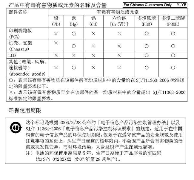
3 CE Conformity Marking Anritsu affixes the CE Conformity marking onto its conforming products in accordance with Council Directives of The Council Of The European Communities in order to indicate that these products conform to the EMC and LVD directive of the European Union (EU). C-tick Conformity Marking Anritsu affixes the C-tick marking onto its conforming products in accordance with the electromagnetic compliance regulations of Australia and New Zealand in order to indicate that these products conform to the EMC regulations of Australia and New Zealand. Notes On Export Management This product and its manuals may require an Export License or approval by the government of the product country of origin for re-export from your country. Before you export this product or any of its manuals, please contact Anritsu Company to confirm whether or not these items are export-controlled. When disposing of export-controlled items, the products and manuals need to be broken or shredded to such a degree that they cannot be unlawfully used for military purposes. Mercury Notification This product uses an LCD backlight lamp that contains mercury. Disposal may be regulated due to environmental considerations. Please contact your local authorities or, within the United States, the Electronics Industries Alliance ( for disposal or recycling information.

4

5 Safety Symbols To prevent the risk of personal injury or loss related to equipment malfunction, Anritsu Company uses the following symbols to indicate safety-related information. For your own safety, please read the information carefully before operating the equipment. Symbols Used in Manuals Danger This indicates a very dangerous procedure that could result in serious injury or death, and possible loss related to equipment malfunction, if not performed properly. Warning This indicates a hazardous procedure that could result in light-to-severe injury or loss related to equipment malfunction, if proper precautions are not taken. Caution This indicates a hazardous procedure that could result in loss related to equipment malfunction if proper precautions are not taken. Safety Symbols Used on Equipment and in Manuals The following safety symbols are used inside or on the equipment near operation locations to provide information about safety items and operation precautions. Ensure that you clearly understand the meanings of the symbols and take the necessary precautions before operating the equipment. Some or all of the following five symbols may or may not be used on all Anritsu equipment. In addition, there may be other labels attached to products that are not shown in the diagrams in this manual. This indicates a prohibited operation. The prohibited operation is indicated symbolically in or near the barred circle. This indicates a compulsory safety precaution. The required operation is indicated symbolically in or near the circle. This indicates a warning or caution. The contents are indicated symbolically in or near the triangle. This indicates a note. The contents are described in the box. These indicate that the marked part should be recycled. MS203xA Revision B Safety-1

6 For Safety Warning Always refer to the operation manual when working near locations at which the alert mark, shown on the left, is attached. If the operation, etc., is performed without heeding the advice in the operation manual, there is a risk of personal injury. In addition, the equipment performance may be reduced. Moreover, this alert mark is sometimes used with other marks and descriptions indicating other dangers. Warning When supplying power to this equipment, connect the accessory 3-pin power cord to a 3-pin grounded power outlet. If a grounded 3-pin outlet is not available, use a conversion adapter and ground the green wire, or connect the frame ground on the rear panel of the equipment to ground. If power is supplied without grounding the equipment, there is a risk of receiving a severe or fatal electric shock. Warning This equipment can not be repaired by the operator. Do not attempt to remove the equipment covers or to disassemble internal components. Only qualified service technicians with a knowledge of electrical fire and shock hazards should service this equipment. There are high-voltage parts in this equipment presenting a risk of severe injury or fatal electric shock to untrained personnel. In addition, there is a risk of damage to precision components. Warning Use two or more people to lift and move this equipment, or use an equipment cart. There is a risk of back injury if this equipment is lifted by one person. Caution Electrostatic Discharge (ESD) can damage the highly sensitive circuits in the instrument. ESD is most likely to occur as test devices are being connected to, or disconnected from, the instrument s front and rear panel ports and connectors. You can protect the instrument and test devices by wearing a static-discharge wristband. Alternatively, you can ground yourself to discharge any static charge by touching the outer chassis of the grounded instrument before touching the instrument s front and rear panel ports and connectors. Avoid touching the test port center conductors unless you are properly grounded and have eliminated the possibility of static discharge. Repair of damage that is found to be caused by electrostatic discharge is not covered under warranty. Safety Revision B MS203xA
7 Table of Contents Chapter 1 General Information 1-1 Introduction Required Test Equipment for Performance Verification Replaceable Parts Chapter 2 Performance Verification 2-1 Introduction Performance Verification Spectrum Analyzer Verification Spectrum Analyzer RF Input VSWR Check Spectrum Analyzer Frequency Accuracy Spectrum Analyzer Internal Reference Frequency Adjustment Spectrum Analyzer SSB Phase Noise Verification Spectrum Analyzer Resolution Bandwidth Accuracy Spectrum Analyzer Displayed Average Noise Level (DANL) Spectrum Analyzer Absolute Amplitude Accuracy Amplitude Accuracy Across Frequency Verification MHz Amplitude Accuracy Verification Power Meter Verification Power Meter Measurement Accuracy Vector Network Analyzer Functions Frequency Accuracy Return Loss Verification Accuracy System Dynamic Range Options Verification Power Monitor (Option 5) Verification Bias Tee (Option 10) Verification Low Current Test High Current Test Fault Test GPS (Option 31) Verification Chapter 3 Remove and Replace Instructions 3-1 Introduction Battery Pack Information Battery Pack Removal and Replacement Opening the MS203xA Case To open the MS203xA case: Removing the Spectrum Analyzer PCB Removing the VNA Module Removing the Main PCB/LCD Assembly MS203xA Revision B Contents-1
8 3-7 Removing the LCD and Backlight Driver PCB from the Main PCB Replacement Main PCB Real Time Clock (RTC) Battery Removal and Replacement Main Keypad Membrane and PCB Replacement Replacing the Function Key Keypad Function Key Membrane and Switchpad Replacement Chapter 4 Troubleshooting 4-1 Introduction Turn-on Problems Unit cannot boot-up, no activity occurs when the On/Off key is pressed: Unit begins the boot process, but does not complete boot-up: Unit makes normal boot-up sounds, but the display has a problem: Boot-up Self Test fails: Battery Pack Charging Problems Operating Problems Lock Error Messages: Option 5, Power Monitor, Problems: Spectrum Analyzer Problems: Cable and Antenna Analyzer Problems: Other Problems: Appendix A Test Records A-1 Spectrum Analyzer RF Input VSWR A-2 A-2 Spectrum Analyzer Frequency Accuracy A-2 A-3 Spectrum Analyzer SSB Phase Noise Verification A-2 A-4 Spectrum Analyzer Resolution Bandwidth Accuracy A-3 A-5 Spectrum Analyzer DANL (Pre-Amp on) A-3 A-6 Spectrum Analyzer Absolute Amplitude Accuracy Characterization Chart A-4 A-7 Spectrum Analyzer Absolute Amplitude Accuracy Measured Values A-5 Characterization Chart for 50 MHz Amplitude Accuracy Verification A-8 A-8 50 MHz Amplitude Accuracy Verification A-9 A-9 Power Meter Measurement Accuracy A-10 Input Power Level at 50 MHz A-10 Input Power Level at MHz A-10 A-10 VNA Frequency Accuracy A-12 A-11 VNA Return Loss Accuracy A-12 A-12 VNA System Dynamic Range MS2034A A-13 A-13 VNA System Dynamic Range MS2036A A-13 A-14 Option 5 Power Monitor Accuracy Verification A-13 A-15 Option 31 GPS Receiver Verification - Spectrum Analyzer Frequency Accuracy A-14 Appendix B Test Fixture Schematics Revision B MS203xA
9 Chapter 1 General Information 1-1 Introduction This manual provides maintenance instructions for the Model MS2034A and Model MS2036A VNA Master. It provides performance verification procedures, battery pack information, parts replacement procedures, and a replaceable parts list. Appendix A contains blank test records which should be copied before use. Familiarity with the basic operation of the front panel keys is assumed (for example, how to change measurement mode, preset the unit, or the meaning of "soft key"). Refer to the VNA Master user guide (Anritsu part number ). Note Before making any measurement, verify that that all equipment has warmed up for at least 30 minutes. MS203xA Revision B 1-1
10 Required Test Equipment for Performance Verification 1-2 Required Test Equipment for Performance Verification The following equipment is required for the Spectrum Analyzer Verification, Power Meter Verification, Vector Network Analyzer Functions, and Options Verification tests that are described in Chapter 2, Performance Verification. Each test section has a table that lists the specific equipment (from this list) that is required for that test. Instrument Critical Specification Recommended Manufacturer/Model Synthesized Signal Source Frequency: 0.1 Hz to 20 GHz Power Output to +13 dbm Anritsu Model MG3692A or MG3692B with the following options a : 2A, 4, 22, 15 Power Meter Power Range: 70 to + 20 dbm Anritsu Dual Channel Model ML2438A Power Sensor Frequency: 10 MHz to 18 GHz Anritsu Model MA2442D (quantity 2) Power Range: 67 to +20 db RF Detector Frequency: 10 MHz to 20 GHz Anritsu Model 560-7N50B Frequency Reference Frequency: 10 MHz Symmetricom Model RubiSource T&M Frequency Counter Frequency: 2 GHz Anritsu Model MF2412B Fixed Attenuator 10 db Attenuation Aeroflex/Weinschel Model (quantity 2) GPS Antenna Anritsu Part Number VNA Master External Power Anritsu Part Number R Supply Test Fixture, High Current Load Resistance: 40 Ohm Anritsu Model T2904 Power: 5 Watts Test Fixture, Low Current Load Resistance: 105 Ohm Anritsu Model T3377 Power: 1 Watts Power Splitter Frequency: DC to 18 GHz Aeroflex/Weinschel Model 1870A Adapter Frequency: DC to 20 GHz Anritsu Model 34NN50A N(m)-N(m), 50 Ohm Adapter Frequency: DC to 20 GHz Anritsu Model 34RKNF50 K(m)-N(f), 50 Ohm Open/Short Anritsu Model 22N50 50 Ohm Termination (N male) Frequency: DC to 18 GHz Anritsu Model 28N50-2 Return Loss: 40 db minimum 50 Ohm Termination (N female) Frequency: DC to 18 GHz Anritsu Model 28NF50-2 Return Loss: 40 db minimum 6 db Offset Termination Anritsu Model SC db Offset Termination Anritsu Model SC7423 RF Coaxial Cable Frequency: DC to 18 GHz Anritsu Model 15NN50-0.6B N(m)-N(m), 50 Ohm RF Coaxial Cable Frequency: DC to 6 GHz Anritsu Model 15NN50-1.5C N(m)-N(m) Coaxial Cable BNC(m) to BNC(m), 50 Ohm any Vector Network Analyzer Frequency: 10 MHz to 9 GHz Anritsu Model MS4624B Calibration Kit N Connector Anritsu 3753R a.option 15 is required for MG3692A models to achieve power of +13 dbm. MG3692B models do not require Option Revision B MS203xA
11 1-3 Replaceable Parts Replaceable Parts To ensure that the correct options are provided on the replacement unit when ordering a Main/Spectrum Analyzer PCB Assembly, all options that are installed in your instrument must be declared on the order. The installed options are listed on a label on the top of the MS203xA and can also be viewed in the System/Status display. Part Number Description ND66453 MS2034A Main/Spectrum Analyzer PCB Assembly for Serial Numbers < ND66454 MS2034A Main/Spectrum Analyzer PCB Assembly, with Option 31 for Serial Numbers < ND66455 MS2036A Main/Spectrum Analyzer PCB Assembly for Serial Numbers < ND66456 MS2036A Main/Spectrum Analyzer PCB Assembly, with Option 31 for Serial Numbers < ND66124 VNA Module Exchange Assembly for Serial Numbers < ND66432 Power Monitor (Option 5) Exchange Assembly ND68045 MS2034A Main/Spectrum Analyzer PCB Assembly, support Option 31, for Serial Numbers > ND68046 MS2036A Main/Spectrum Analyzer PCB Assembly, support Option 31, for Serial Numbers > ND68536 VNA Module Assembly, for Serial Numbers > LCD Display Clear plastic LCD protector LCD Backlight Inverter PCB Soft Carrying Case Case Top (excludes model ID Label and keypad items) Case Bottom (excludes tilt bail) Model MS2034A ID Label Model MS2036A ID Label Battery Door Li-ion Battery Pack ND64383 Fan v RTC Battery R AC to DC Power Converter Internal Compact Flash Card (256 MB) Main Keypad PCB Main Keypad Main Keyboard Bezel Softkeys Keypad Softkey Bezel Softkey PCB Speaker Encoder (excluding knob) Encoder Knob (excluding encoder) MS203xA Revision B 1-3
12 Replaceable Parts Revision B MS203xA
13 Chapter 2 Performance Verification 2-1 Introduction This chapter provides procedures to verify performance, and Appendix A contains blank test records, which should be copied before use. Familiarity with the basic operation of the front panel keys is assumed (for example, how to change measurement mode, preset the unit, or the meaning of "soft key"). Note Before making any measurement, verify that that all equipment has warmed up for at least 30 minutes. 2-2 Performance Verification The sections below contain tests that can be used to verify the performance of the Model MS203xA. Section Spectrum Analyzer Verification contains instructions to verify the Spectrum Analyzer functions, Section Power Meter Verification contains instructions to verify the Power Meter function, Section Vector Network Analyzer Functions contains instructions to verify the Vector Network Analyzer functions, and Section Options Verification contains instructions to verify Options. Each Section begins with a list of required equipment applicable to that section. Copy the appropriate blank test record in Appendix A and use it to record measured values. MS203xA Revision B 2-1
14 Spectrum Analyzer Verification 2-3 Spectrum Analyzer Verification Required Equipment: Table 2-1. Equipment Required for Spectrum Analyzer Verification Instrument Critical Specification Recommended Manufacturer/Model Synthesized Signal Source Frequency: 0.1 Hz to 20 GHz Anritsu Model MG3692A or MG3692B with the Power Output to +13 dbm following options a : 2A, 4, 22, 15 Power Meter Power Range: 70 to + Anritsu Dual Channel Model ML2438A 20 dbm Power Sensor Frequency: 10 MHz to 18 GHz Anritsu Model MA2442D (quantity 2) Power Range: 67 to +20 db Frequency Reference Frequency: 10 MHz Symmetricom Model RubiSource T&M Fixed Attenuator 10 db Attenuation Aeroflex/Weinschel Model (quantity 2) Power Splitter Frequency: DC to 18 GHz Aeroflex/Weinschel Model 1870A Adapter Frequency: DC to 20 GHz Anritsu Model 34NN50A N(m)-N(m), 50 Ohm Adapter Frequency: DC to 20 GHz Anritsu Model 34RKNF50 K(m)-N(f), 50 Ohm 50 Ohm Termination Frequency: DC to 18 GHz Anritsu Model 28N50-2 RF Coaxial Cable Frequency: DC to 18 GHz Anritsu Model 15NN50-0.6B N(m)-N(m), 50 Ohm Coaxial Cable BNC(m) to BNC(m), 50 Ohm any Vector Network Analyzer Frequency: 10 MHz to 9 GHz Anritsu Model MS4624B Calibration Kit N Connector Anritsu 3753R a. Option 15 is required for MG3692A models to achieve power of +13 dbm. MG3692B models do not require Option 15. Spectrum Analyzer RF Input VSWR Check This test verifies that the Spectrum Analyzer RF Input meets VSWR specification. Procedure: 1. Connect a 15NN50-0.6B cable to Port 1 of VNA MS4624B. 2. Perform a Reflection Only calibration at the open end of the cable using the 3753R Calibration Kit. Set the Test Port Connector Type to N male. 3. Change the MS4624B display to S11 Single Channel and SWR. 4. Connect the open end of the cable to the Spectrum Analyzer RF In connector. 5. Use a Marker to find the maximum value, and record the marker reading into the Measured Value column in Table A-1, Spectrum Analyzer RF Input VSWR, in Appendix A. Spectrum Analyzer Frequency Accuracy This test verifies the Frequency Accuracy of the Spectrum Analyzer. Procedure: 1. Connect the external 10 MHz Reference to the Anritsu MG3692X Synthesized Signal Source. 2. Do not connect the external 10 MHz Reference to the MS203xA. 3. Connect the output of the synthesizer to the Spectrum Analyzer RF In of the MS203xA. 4. On the MS203xA, change the Mode to Spectrum Analyzer and Preset the unit Revision B MS203xA
15 Spectrum Analyzer Verification 5. Set the MG3692A or MG3692B output to 1 GHz CW, with an RF output level of 30 dbm. 6. On the MS203xA, press the Amplitude key, and set the Reference Level to 10 dbm. 7. Press the Freq key and set the Center Freq to 1.0 GHz. 8. Press the Span key, set the span to 10 khz. 9. Press the BW key and set RBW to 100 Hz. 10. Press the VBW soft key and set to 30 Hz. 11. On the MS203xA, press the Marker key, and press the Peak Search soft key. 12. Record the marker frequency in Table A-2, Spectrum Analyzer Frequency Accuracy in Appendix A. Verify that it is within specification. 13. For MS2036A, continue to next step. For MS2034A, go to the next section. 14. Set the synthesizer for 7.0 GHz and set the center frequency of the MS2036A to 7.0 GHz. 15. On the MS2036A, press the Marker key, and press the Peak Search soft key. 16. Record the marker frequency in Table A-2 in Appendix A. Verify that it is within specification. If the unit fails the Spectrum Analyzer Frequency Accuracy test, then perform the Spectrum Analyzer Internal Reference Frequency Adjustment procedure in the following section. If the unit still fails the Frequency Accuracy test after the Internal Reference Frequency adjustment has been completed, then replace the PCB assembly. MS203xA Revision B 2-3

16 Spectrum Analyzer Verification Spectrum Analyzer Internal Reference Frequency Adjustment Use this procedure to adjust the frequency if the unit fails the Spectrum Analyzer Frequency Accuracy verification test in the previous section. Procedure: 1. Connect the external 10 MHz Reference to the Anritsu MG3692A or MG3692B Synthesized Signal Source. Do not connect the external 10 MHz Reference to the MS203xA. 2. Connect the output of the synthesizer to the Spectrum Analyzer RF In of the MS203xA. 3. On the MS203xA, Verify that the unit is in the Spectrum Analyzer mode and Preset the unit. 4. Set the MG3692A or MG3692B output to 1 GHz with an RF output level of 30 dbm. 5. On the MS203xA, press the Amplitude key and set the Reference Level to 10 dbm. 6. Set the Atten Lvl to 0 db. 7. Press the Freq key and set the Center Freq to 1.0 GHz. 8. Press the Span key, use the keypad to enter 10, and press the khz soft key. 9. Press the BW key and set the RBW to 100Hz. 10. Press the VBW soft key and set to 30 Hz. 11. Press and hold the Shift key and press the 4th, 6th, and 8th (below Esc) soft keys together in order to enter into the MS203xA Service Mode (Figure 2-1). Figure 2-1. MS203xA Service Mode 12. Press the Service Menu soft key, then the APP Service soft key. 13. Press the Calibration soft key, then the 10 MHz Ref soft key. 14. Use the Up/Down arrow keys or the rotary knob to slowly adjust the displayed signal to the center of the display. Allow the signal to stabilize between adjustments, and repeat as necessary. 15. Turn the MS203xA Off, and then back On, to exit Service Mode Revision B MS203xA
17 Spectrum Analyzer SSB Phase Noise Verification Spectrum Analyzer Verification This test can be used to verify the single side band phase noise of the MS203xA. Procedure: 1. Connect the external 10 MHz Reference to the Anritsu MG3692A or MG3692B Synthesized Signal Source. 2. Connect the output of the synthesizer to the Spectrum Analyzer RF In connector of the MS203xA. 3. Set the MG3692A or MG3692B output to 900 MHz CW, with an RF output level of +3 dbm. 4. Verify that the MS203xA is in the Spectrum Analyzer mode. Preset the unit. 5. Press the Amplitude key, then set the Reference Level to 0 dbm. 6. Press the Atten Lvl soft key, enter 15 db. 7. Press the Freq key and set the Center Freq to 900 MHz. 8. Press the Span key, set to 210 khz. 9. Press the BW key and set the RBW to 1 khz. 10. Press the VBW soft key set to 3 Hz. 11. Press the Shift key and then press the Trace (5) key. 12. Press Trace A Operations, and set the # of Averages to Wait until the Trace Count (left side of display) displays 7/ Press the Marker key and press the Peak Search soft key. 15. Press the Delta On/Off soft key to turn Delta On. 16. Use the keypad to enter 10 and press the khz soft key. 17. Subtract 30 from the db value shown on the marker readout to convert the value to dbc/hz (for example, if the marker reads 80 db, then the value becomes 110 dbc/hz. Record the dbc/hz value in Table A-3, Spectrum Analyzer SSB Phase Noise Verification in Appendix A. 18. Repeat Step 16 and Step 17 for 20 khz marker delta, 30 khz marker delta, and 100 khz marker delta. MS203xA Revision B 2-5
18 Spectrum Analyzer Verification Spectrum Analyzer Resolution Bandwidth Accuracy This test checks the accuracy of the resolution bandwidth settings. 1. Connect the external 10 MHz Reference to both the MG3692x synthesized Source and to the MS203xA VNA Master. 2. Verify that the mode of the MS203xA is set to Spectrum Analyzer. Preset the unit. 3. Set the MS203xA as follows: a. Center Frequency: 1.0 GHz b. Reference Level: 10 dbm c. Attenuation Level: 0 db 4. Set the MG3692A or MG3692B to 1 GHz, with an output level of 30 dbm. Apply the signal to the spectrum analyzer input of the MS203xA. 5. Set the Span of the MS203xA to 4.5 MHz. 6. Press the BW key and set the RBW to 3 MHz. 7. Under the Measure menu, press OCC BW and set it to On. 8. Press the dbc soft key and enter Record the occupied bandwidth in Table A-4, Spectrum Analyzer Resolution Bandwidth Accuracy in Appendix A and verify it is within specification. 10. Repeat Step 5 through Step 9 for all other settings on the test record. Spectrum Analyzer Displayed Average Noise Level (DANL) The following test can be used to verify the Displayed Average Noise Level of the MS203xA. This test is performed using the RMS detection mode, with pre-amp on. Procedure: 1. Connect the 50 Ohm termination to the MS203xA Spectrum Analyzer RF In. 2. Verify that the MS203xA is in the Spectrum Analyzer mode. Preset the unit. 3. Press the Amplitude key and set Atten Lvl to 0 db. 4. Press the Reference Level soft key and set to 50 dbm. 5. Press the Pre-amp On/Off soft key to turn it On. 6. Press the Shift key and then press the Sweep (3) key, then press Detection, then press RMS. 7. Press the BW key. Select RBW of 100 khz, and select VBW according to the test record in Table A-5, Spectrum Analyzer DANL (Pre-Amp on) in Appendix A 8. Enter the Start and Stop frequencies (press the Freq key) from Table A-5 in Appendix A. 9. Wait until 1 sweep has completed. 10. Press the Marker key and press the Peak Search soft key. 11. Record the Marker reading in the Measured dbm (100 khz) column of Table A Repeat Step 8 through Step 11 for the other frequencies on the list. For each measured 100 khz value in Table A-5, convert this to 10 Hz RBW value by subtracting 40 db. For example, if the marker shows a value of 110 dbm at 100 khz RBW, the computed value at 10 Hz RBW is 150 dbm.) Enter the computed values or 174 dbm, whichever is higher, in Table A Revision B MS203xA

19 Spectrum Analyzer Verification Spectrum Analyzer Absolute Amplitude Accuracy The tests in this section verify the level accuracy of the MS203xA Spectrum Analyzer. This test has two parts: Amplitude Accuracy Across Frequency Verification 50 MHz Amplitude Accuracy Verification Amplitude Accuracy Across Frequency Verification Amplitude Accuracy Across Frequency Verification Setup Procedure: 1. Connect both MA2442D power sensors to the power meter and calibrate the sensors. 2. Connect the model 1870A power splitter to the MG3692A or MG3692B output and Sensor B to one of the power splitter outputs (Refer to Figure 2-2). 3. Install the 10 db Fixed Attenuator to the other power splitter output and then connect Sensor A to the end of the Attenuator. 34RSN50 ADAPTER MG369XA SOURCE 15NNF50-1.5C SENSOR B SENSOR A N241A50 ATTENUATOR A B ML2438A POWER METER Figure 2-2. Component Characterization 4. Set the frequency of the MG3692A or MG3692B to the first (then to the next) frequency in Table A-6, Spectrum Analyzer Absolute Amplitude Accuracy Characterization Chart in Appendix A. 5. Set the Model ML2438A power meter to display both Channel A and Channel B. Press the Sensor key, the Cal Factor soft key, and then the Freq soft key. Use the keypad to enter the value matching the frequency of MG3692A or MG3692B as the input signal frequency, which sets the power meter to the proper power sensor calibration factor. Repeat for Channel B. Press the System key to display the power reading. 6. Adjust the power level of the MG3692A or MG3692B so that Sensor A reads 2.0 dbm. 7. Record the Sensor B reading in the 2 dbm column in Table A Repeat Step 4 through Step 7 for all the frequencies in Table A Repeat Step 4 through Step 7 for a power level of 30.0 dbm, and record those values in the 30 dbm column of Table A Remove Sensor A from the attenuator output, install the 34NN50A adapter to the end of the Attenuator, and connect the splitter/attenuator fixture to the MS203xA as shown in Figure 2-3. To maintain test setup integrity, do not disconnect Sensor B, the power splitter, or the fixed attenuator. MS203xA Revision B 2-7

20 Spectrum Analyzer Verification ML2438A POWER METER SENSOR B MA2442A 15NNF50-1.5C MG3692A SOURCE 34RSN50 ADAPTER 10 db ATTENUATOR N241A50 34NN50A ADAPTER Figure 2-3. Test Setup for Amplitude Accuracy Across Frequency Verification Amplitude Accuracy Across Frequency Verification Test Procedure: Use Table A-6, Spectrum Analyzer Absolute Amplitude Accuracy Characterization Chart on page A-4 to complete the Amplitude Accuracy Across Frequency Verification test record as follows: 1. Verify that the MS203xA is in the Spectrum Analyzer mode. Preset the unit. 2. On the MS203xA, press the Amplitude key and then set the Reference Level to 20 dbm. 3. Set the Atten Lvl to 0 db. 4. Press the BW key and set the RBW to 1 khz. 5. Set the VBW to 10 Hz. 6. Press the Span key and set span to 10 khz. 7. Press the Freq key and press the Center Freq soft key. 8. Enter 50 MHz (or the next frequency). 9. Set the Model ML2438A power meter to display Channel B. Press the Sensor key, the Cal Factor soft key, and then the Freq soft key. Use the keypad to enter the value matching the frequency of MG3692A or MG3692B as the input signal frequency, which sets the power meter to the proper power sensor calibration factor. Press the System key to display the power reading. 10. Set the MG3692A or MG3692B output to match the frequency in the preceding step. 11. Adjust the MG3692A or MG3692B power level so that the Sensor B for the power meter displays the Sensor B reading in Table A-6, Spectrum Analyzer Absolute Amplitude Accuracy Characterization Chart for 30 dbm. 12. Press the Marker key and press the Peak Search soft key. 13. Record the Marker 1 amplitude reading in the Measured Value column in Table A-7, Measured Values for 30dBm, 0dB Attenuation in Appendix A. 14. Verify that the Marker 1 amplitude reading is within the specification Revision B MS203xA
21 Spectrum Analyzer Verification 15. Repeat Step 7 to Step 14 for the other frequencies in column 1 of the Amplitude Accuracy Across Frequency Verification tables (Table A-7 through Table A-11). 16. Set the MS203xA Atten Lvl to 5 db and repeat Step 7 to Step 14. Record the Marker 1 amplitude reading in the Measured Value column in Table A-8, Measured Values for 30 dbm, 5 db Attenuation. 17. Set the MS203xA Atten Lvl to 10 db and repeat Steps 7 to Step 14. Record the Marker 1 amplitude reading in the Measured Value column in Table A-9, Measured Values for 30 dbm, 10 db Attenuation. 18. Set the MS203xA Atten Lvl to 20 db and repeat Steps 7 to Step 14. Record the Marker 1 amplitude reading in the Measured Value column in Table A-10, Measured Values for 30 dbm, 20 db Attenuation. 19. Set the MS203xA Reference Level to 10 dbm and the Atten Lvl to 30 db. 20. Repeat Step 7 to Step 14, but adjust the MG3692A or MG3692B power level so that the Sensor B of the power meter displays the Sensor B reading in Table A-6, Spectrum Analyzer Absolute Amplitude Accuracy Characterization Chart for 2 dbm. Record the Marker 1 amplitude reading in the Measured Value column in Table A-11, Measured Values for 2 dbm, 30 db Attenuation. MS203xA Revision B 2-9
22 Spectrum Analyzer Verification 50 MHz Amplitude Accuracy Verification 50 MHz Amplitude Accuracy Verification Setup: 1. Connect both MA2442D power sensors to the Model ML2438A power meter and calibrate the sensors. 2. Set the frequency of the MG3692A or MG3692B to 50 MHz. 3. Connect the equipment as shown in Figure 2-2 on page Set the power meter to display both Channel A and Channel B. 5. Press the Sensor key, the Cal Factor soft key, then the Freq soft key and use the keypad to enter the value matching the frequency of MG3692A or MG3692B as the input signal frequency, which sets the power meter to the proper power sensor calibration factor. Repeat for Channel B. Press the System key to display the power reading. 6. Adjust the power level of the MG3692A or MG3692B to get a reading on Sensor A that matches the power level in the first column of Table A-12, Characterization Chart for 50 MHz Amplitude Accuracy Verification in Appendix A. 7. Record the Sensor B reading in the Required Sensor B Reading column in Table A Repeat Step 6 and Step 7 for the other power levels in the first column of Table A-12, recording the Sensor B reading in the second column. 50 MHz Amplitude Accuracy Verification Test Procedure: 1. Connect the equipment as shown in Figure 2-3 on page Verify that the MS203xA is in the Spectrum Analyzer mode. Preset the unit. 3. Press the Freq key and set the MS203xA Center Frequency to 50 MHz. 4. Press the BW key and set the RBW to 1 khz. 5. Set the VBW to 10 Hz. 6. Press the Span key and set the span to 10 khz. 7. Press the Amplitude key and set the Reference Level to 10 dbm. 8. Set the Atten Lvl to 30 db. 9. Adjust the MG3692A or MG3692B power so that the power meter Sensor B matches the Sensor B value that is shown in Table A Press the Marker key and press the Peak Search soft key. 11. Record the Marker 1 amplitude reading in Table A-13, 50 MHz Amplitude Accuracy Verification in Appendix A. 12. Repeat Step 9 through Step 11 for the other power level settings. Change Reference Level and Atten Lvl as indicated in Table A Revision B MS203xA
23 Power Meter Verification 2-4 Power Meter Verification Required Equipment Table 2-2. Equipment Required for Power Meter Verification Instrument Critical Specification Recommended Manufacturer/Model Synthesized Signal Source Frequency: 0.1 Hz to 20 GHz Anritsu Model MG3692A or MG3692B with Power Output to +13 dbm options: 2A, 4, 22, 15 a Power Meter Power Range: 70 dbm to Anritsu Dual Channel Model ML2438A +20 dbm Power Sensor Frequency: 10 MHz to 18 GHz Anritsu Model MA2442D (quantity 2) Power Range: 67 to +20 db Fixed Attenuator 10 db Attenuation Aeroflex/Weinschel Model Power Splitter Frequency: DC to 18 GHz Aeroflex/Weinschel Model 1870A Adapter Frequency: DC to 20 GHz Anritsu Model 34NN50A N(m)-N(m), 50 Ohm Adapter Frequency: DC to 20 GHz Anritsu Model 34RKNF50 K(m)-N(f), 50 Ohm RF Coaxial Cable Frequency: DC to 18 GHz N(m)-N(m), 50 Ohm Anritsu Model 15NN50-0.6B a. Option 15 is required for MG3692A models to achieve power of +13 dbm. MG3692B models do not require Option 15 Power Meter Measurement Accuracy The tests in this section verify the level accuracy of the MS203xA Power Meter function. Component Characterization: 1. Connect both MA2442D power sensors to the Model ML2438A power meter and calibrate the sensors. 2. Connect the model 1870A power splitter to the MG3692A or MG3692B output and connect Sensor B to one of the power splitter outputs (Refer to Figure 2-2). 3. Install the 10 db Fixed Attenuator to the other power splitter output, and then connect Sensor A to the end of the Attenuator. ML2438A POWER METER SENSOR B MA2442A 15NNF50-1.5C MG3692A SOURCE 34RSN50 ADAPTER 10 db ATTENUATOR N241A50 34NN50A ADAPTER Figure 2-4. MS203xA Power Meter Level Accuracy MS203xA Revision B 2-11
24 Power Meter Verification 4. Set the Model ML2438A power meter to display both Channel A and Channel B. Press the Sensor key, the Cal Factor soft key, and then the Freq soft key. Use the keypad to enter the value matching the frequency of MG3692A or MG3692B as the input signal frequency, which sets the power meter to the proper power sensor calibration factor. Repeat for Channel B. Press the System key to display the power reading. 5. Adjust the power level of the MG3692A or MG3692B to get a reading on Sensor A that matches the power level in the first column of Table A-14, Characterization Chart for Test Power Level at 50 MHz in Appendix A. 6. Record the Sensor B reading in the Required Sensor B Reading column in Table A Repeat Step 5 and Step 6 for the other power level in the first column of Table A-14, recording the Sensor B reading in the second column of the table. 8. Repeat Step 5 through Step 7 for the next input frequencies ( MHz for MS2034A and 7000 MHz for MS2036A). Use Table A-16, Characterization Chart for Test Power Level at MHz and Table A-18, Characterization Chart for Test Power Level at 7000 MHz in Appendix A. Procedure: 1. Connect the equipment as shown in Figure Verify that the MS203xA is in the Power Meter mode. Preset the unit. 3. Set the MS203xA Span to 3 MHz. 4. Set the MS203xA Center Frequency to 50 MHz. 5. Adjust the MG3692A or MG3692B power so that the power meter value for Sensor B matches the first Sensor B value that is shown in Table A-14, Characterization Chart for Test Power Level at 50 MHz. 6. Record the reading on the MS203xA display in Table A-15, Input Power Level at 50 MHz in Appendix A. 7. Repeat Step 4 through Step 6 for the next test power level in Table A-14 and Table A Repeat Step 4 through Step 7 for the next test frequencies. Use Table A-16, Characterization Chart for Test Power Level at MHz and Table A-17, Input Power Level at MHz. Then use Table A-18, Characterization Chart for Test Power Level at 7000 MHz and Table A-19, Input Power Level at 7000 MHz Revision B MS203xA
25 Vector Network Analyzer Functions 2-5 Vector Network Analyzer Functions Required Equipment Table 2-3. Equipment Required for Vector Network Analyzer Functions Instrument Critical Specification Recommended Manufacturer/Model Frequency Counter Frequency: 2 GHz Anritsu Model MF2412B Open/Short Anritsu Model 22N50 Termination (N male) Frequency: DC to 18 GHz Anritsu Model 28N50-2 Return Loss: 40 db minimum Termination (N female) Frequency: DC to 18 GHz Anritsu Model 28NF50-2 Return Loss: 40 db minimum RF Coaxial Cable Frequency: DC to 18 GHz Anritsu Model 15NN50-0.6B N(m)-N(m), 50 Ohm Coaxial Cable BNC(m) to BNC(m), 50 Ohm any 6 db Offset Termination Anritsu Model SC db Offset Termination Anritsu Model SC7423 Frequency Accuracy The following test can be used to verify the CW frequency accuracy of the RF source in the MS203xA. Procedure: 1. Verify that the MS203xA is in Vector Network Analyzer mode. Preset the unit. 2. Verify that that no external 10 MHz reference is connected to the MS203xA. 3. Press Shift, Sweep (3). 4. Verify that the RF Immunity is set to Normal. 5. Press the Freq/Dist key and set the Center Frequency to 2.0 GHz, and the Span to 0 Hz. 6. Connect the RF cable from the MS203xA VNA Reflection RF Out to the Frequency Counter. 7. Turn on the Frequency Counter and press the Preset key. 8. Record the frequency data in Table A-20, VNA Frequency Accuracy in Appendix A. Return Loss Verification Accuracy The following test can be used to verify the accuracy of return loss measurements. Measurement calibration of the MS203xA is required for this test. Procedure: 1. Verify that the MS203xA is in Vector Network Analyzer mode. Preset the unit. 2. Press the Measurement key, then press the S11 Reflection soft key. 3. Press the Log Magnitude soft key (a red dot will appear on that label). 4. Press Shift, then Calibrate (2). 5. Press the Start Cal soft key. Follow the instructions on the screen to perform a calibration. (Connect the RF components directly onto the VNA Reflection RF Out connector). 6. After the calibration is complete, install the 6 db offset termination. 7. Press the Scale key, change Reference Value to 6 db, and change Resolution per Div to 1 db. 8. Select the Limits menu, turn the Upper Limit On and set it to 5.05 db. MS203xA Revision B 2-13
26 Vector Network Analyzer Functions 9. Turn the Lower Limit On and set it to 6.95 db. Note that the MS203xA rounds off the value on the display to one decimal place (for example, xx.x). 10. Verify that the data display falls between the Limit Lines. 11. Press the Marker key to activate the marker menu. 12. Press Peak Search and record the MARKER 1 readout value. 13. Press Valley Search and record the MARKER 1 readout value. 14. Record the MARKER 1 value that has the larger delta from the Reference Value into the Measured Value column in Table A-21, VNA Return Loss Accuracy in Appendix A. 15. Remove the 6 db offset termination and install the 20 db termination. 16. Press the Scale key, Change Reference Value to 20 db. 17. Select the Limits menu, turn the Upper Limit On and set it to db. 18. Turn the Lower Limit On and set it to db. 19. Verify that the data display falls between the Limit Lines. 20. Press the Marker key to activate the marker menu. 21. Press Peak Search and record the MARKER 1 readout value. 22. Press Valley Search and record the MARKER 1 readout value. 23. Record the MARKER 1 value that has the larger delta from the Reference Value in Table A-21. System Dynamic Range The following test can be used to verify the system dynamic range. Measurement calibration of the MS203xA is required for this test. Procedure 2 MHz to 10 MHz: 1. Verify that the MS203xA is in Vector Network Analyzer mode. Preset the unit. 2. Install an N male to N male cable to the VNA Reflection RF Out connector. Leave the other end of the cable unconnected. 3. Press the Freq/Dist key and set the Stop Frequency to 10 MHz. 4. Press the Measurement key, then press S21 Tramsmission. 5. Verify that Log Magnitude is selected (red dot appears on the label). 6. Press the Shift key, then press the Sweep (3) key. 7. Set RF Immunity to High 8. Press the Shift key, then press the Calibrate (2) key. 9. Verify that the Cal Type is set to 2-Port and the Cal Power is set to High. 10. Press the Start Cal soft key and follow the on screen instructions to perform the calibration. 11. After the Calibration is complete, disconnect one end of the cable and connect Loads so that both the VNA Reflection RF Out and VNA RF In Port are terminated. 12. Press Shift, Sweep (3), and press Averaging. Verify that Averaging is set to Off. 13. Press the Scale key and set Resolution per Div to 10 db, and set Reference Value to 60 db. 14. Press Shift, Limit (6), and set the Upper Limit to On. 15. Press the Limit Edit soft key. 16. Press Move Limit and set the limit to 70 db. 17. Verify that the entire RF trace falls under the limit line. 18. Press the Marker key to activate the marker menu Revision B MS203xA
27 Vector Network Analyzer Functions 19. Press Peak Search and record the MARKER 1 readout value into the Measured Value column in Table A-22, VNA System Dynamic Range MS2034A or Table A-23, VNA System Dynamic Range MS2036A in Appendix A. Procedure 10 MHz to 3.0 GHz: 1. Verify that the MS203xA is in Vector Network Analyzer mode. Preset the unit. 2. Press the Freq/Dist key and set the Start Frequency to 10 MHz and the Stop Frequency to 3.0 GHz. 3. Repeat Step 8 through Step 19 in section Procedure 2 MHz to 10 MHz: with the upper limit set to 80 db. Procedure 3.0 GHz to 4.0 GHz or 5.5 GHz: 1. Verify that the MS203xA is in Vector Network Analyzer mode. Preset the unit. 2. Press the Freq/Dist key and set the Start Frequency to 3 GHz and set the Stop Frequency to 4 GHz if testing VNA Master model MS2034A (or set Stop Frequency to 5.5 GHz if testing VNA Master model MS2036A). 3. Repeat Step 8 through Step 16 in section Procedure 2 MHz to 10 MHz: with the upper limit set to 70 db. 4. Verify that the entire trace falls under the limit line. 5. Press the Marker key to activate the marker menu. 6. Press Peak Search and record the MARKER 1 readout value into the Measured Value column in Table A-22, VNA System Dynamic Range MS2034A or Table A-23, VNA System Dynamic Range MS2036A. 7. The System Dynamic Range test is complete if the unit is model MS2034A. Continue with the next section for model MS2036A. Procedure 5.5 GHz to 6.0 GHz: 1. Verify that the MS2036A is in Vector Network Analyzer mode. Preset the unit. 2. Press the Freq/Dist key and set the Start Frequency to 5.5 GHz and the Stop Frequency to 6.0 GHz. 3. Repeat Step 8 through Step 16 in section Procedure 2 MHz to 10 MHz: with the upper limit set to 65 db. 4. Verify that the entire RF trace falls under the limit line. 5. Press the Marker key to activate the marker menu. 6. Press Peak Search and record the MARKER 1 readout value into the Measured Value column in Table A-23, VNA System Dynamic Range MS2036A. MS203xA Revision B 2-15
28 Options Verification 2-6 Options Verification Required Equipment Table 2-4. Equipment Required for Options Verification Instrument Critical Specification Recommended Manufacturer/Model Synthesized Signal Source Frequency: 0.1 Hz to 20 GHz Anritsu Model MG3692A or MG3692B with Power Output to +13 dbm options: 2A, 4, 22, 15 a RF Detector (for Option 5) Frequency: 10 MHz to 20 GHz Anritsu Model 560-7N50B Power Meter (for Option 5) Power Range: 70 dbm to + Anritsu Dual Channel Model ML2438A 20 dbm Power Sensor (for Option 5) Frequency: 10 MHz to 18 GHz Anritsu Model MA2442D (quantity 2) Power Range: 67 to +20 db Power Splitter (for Option 5) Frequency: DC to 18 GHz Aeroflex/Weinschel Model 1870A RF Coaxial Cable (for Option 5) Test Fixture (for Option 10) Test Fixture (for Option 10) Frequency: DC to 6 GHz N(m)-N(m) Resistance: 40 Ohm Power: 5 Watts Resistance: 105 Ohm Power: 1 Watt a. Option 15 is required for MG3692A models to achieve power of +13 dbm. MG3692B models do not require option 15. Power Monitor (Option 5) Verification Anritsu Model 15NN50-1.5C Anritsu Model T2904 Anritsu Model T3377 GPS Antenna (for Option 31) Anritsu part number If the Power Monitor (Option 5) is installed in the MS203xA, the following test can be used to verify the accuracy of the power measurements. Procedure: 1. Set the MS203xA to Power Monitor mode. Preset the unit. 2. Install the 560-7N50B detector to the MS203xA. 3. Set the MG3692A or MG3692B output to 1.0 GHz. 4. Connect the power sensor to the Model ML2438A power meter and calibrate the sensor. 5. Connect the equipment as shown in Figure Revision B MS203xA

29 Options Verification 34RKNF50 ADAPTER MG3691A SOURCE 15NN50-1.5C DETECTOR SENSOR 1870A A Figure 2-5. Power Monitor (Option 5) Verification MS2024A ML2437A POWER METER 6. On the Model ML2438A power meter, set the Sensor calibration factor for 1 GHz. 7. On the MG3692A or MG3692B press the Level key, then adjust the power level so that the power meter reads 40.0 dbm. 8. Verify that the MS203xA reading is within the tolerance shown in Table A-24, Option 5 Power Monitor Accuracy Verification in Appendix A. 9. Repeat Step 7 and Step 8 for the other power level settings that are shown in the first column of Table A-24. Bias Tee (Option 10) Verification If the Bias Tee (Option 10) is installed in the VNA Master, the following test can be used to verify the performance of the bias termination. Equipment Required: 105 Ohm, 1 Watt, Low Current Load, Anritsu T Ohm, 5 Watt, High Current Load, Anritsu T2904 VNA Master External Power Supply, Anritsu Part Number R Procedure: 1. Connect the external power supply (Anritsu part number R) to the VNA Master. 2. Press the On/Off key to turn on the VNA Master. 3. Press the Shift key, the Preset (1) key, and then the Preset soft key to reset the instrument to the default starting conditions. Note Before continuing, allow a 30-minute warm up for the internal circuitry to stabilize. 4. Press the Shift key, and then the Sweep (3) key. MS203xA Revision B 2-17
30 Options Verification Low Current Test 1. Press the Bias Tee soft key and then the Bias Tee Voltage soft key. Verify that the Bias Tee voltage is set to 12.0 V and that the Current soft key is set to Low. 2. Press the Bias Tee On/Off soft key to turn the Bias Tee On. 3. Connect the 105 Ohm load to the RF In test port. 4. Verify that the voltage and current readings that are displayed on the left side of the screen are within the specifications that are shown in Table Set the Bias Tee voltage to each of the values in Table 2-5 and verify that the voltage and current readings that are displayed on the left side of the screen are within the specifications that are shown in Table 2-5. Table 2-5. Bias Tee Verification, 105 Ohm Load, Low Current Voltage Setting Voltage Specification Current Specification 12.0 V ± 0.5 V 85 ma to 145 ma 15.0V ±0.6V 113mA to 173mA 18.0V ±0.7V 142mA to 202mA 21.0V ±0.8V 172mA to 230mA 24V ±1.0V 199mA to 259mA Revision B MS203xA
31 High Current Test Options Verification 1. Press the Current soft key to set the Bias Tee current to High. 2. Set the Bias Tee voltage to 12.0 V and verify that the voltage and current readings that are displayed on the left side of the screen are within the specifications that are shown in Table 2-6. Set the Bias Tee voltage to 15.0 V and verify that the voltage and current readings that are displayed on the left side of the screen are within the specifications that are shown in Table 2-6. Table 2-6. Bias Tee Verification, 105 Ohm Load, High Current Voltage Setting Voltage Specification Current Specification 12.0 V ± 0.5 V 85 ma to 145 ma 15.0V ±0.6V 113mA to 173mA 3. Disconnect the 105 Ohm load and connect the 40 Ohm load to the RF In port. 4. Set the Bias Tee voltage to 12.0 V and verify the voltage and current readings displayed on the left side of the screen are within the specifications shown in Table 2-7. Set the Bias Tee voltage to 15.0 V and verify the voltage and current readings displayed on the left side of the screen are within the specifications shown in Table 2-7. Table 2-7. Bias Tee Verification, 40 Ohm Load, High Current Fault Test Voltage Setting Voltage Specification Current Specification 12.0V ±0.5V 250mA to 350mA 15.0V ±0.6V 325mA to 425mA 1. Press the Current soft key and set the Bias Tee current to Low. 2. Set the Bias Tee voltage to 15.0 V. 3. Connect the 40 Ohm load to the RF In port. 4. Verify that the instrument makes a clicking sound and the Bias Tee current reading displayed on the left side of the screen is 0mA. GPS (Option 31) Verification The following test can be used to verify the operation of the GPS option. Procedure: 1. Connect the GPS antenna to the GPS Antenna connector on the MS203xA. Note If no fixed GPS antenna is available, then the Anritsu GPS antenna can be used for this test. Ensure that the Anritsu GPS antenna is in a direct line-of-sight relationship to the satellites, or the antenna must be placed outdoors without any obstructions. 2. Press the Shift key and then the System (8) key. 3. Press the GPS soft key, then press the GPS On/Off soft key to turn the GPS On. 4. When the GPS fix is acquired, the GPS indicator at the top of the LCD display turns green. The latitude and the longitude are displayed next to the GPS indicator. 5. Wait for approximately 3 minutes after the Reference Source indicator in the lower-left-hand corner of the LCD display has changed to GPS High Accuracy. MS203xA Revision B 2-19
32 Options Verification Note If a GPS fix is acquired by using the Anritsu antenna outdoors, then bringing the instrument indoors will cause a loss of the satellite tracking. When the loss occurs, a red cross appears on the green GPS indicator, and the Reference Source indicator changes to Int Hi Accy. The following test will therefore verify frequency to a lesser specification. 6. Connect the external 10 MHz Reference to the Anritsu MG3692x but not to the MS203xA. 7. Connect the output of the MG3692x to the Spectrum Analyzer RF In of the MS203xA. 8. On the MS203xA, change mode to Spectrum Analyzer and preset the MS203xA. 9. Set the MG3692x output to 3.9 GHz CW, with an RF output level of 30 dbm. 10. On the MS203xA, press the Amplitude key, and set the reference level to 10 dbm. 11. Press the Freq key and set the center frequency to 1 GHz. 12. Press the Span key and set the span to 10 khz. 13. Press the BW key and set RBW to 100 Hz. 14. Press the VBW soft key and set VBW to 30 Hz. 15. Press the Marker key, and press the Peak Search soft key. 16. Record the marker frequency in the Measured Value column of Table A-25, Option 31 GPS Receiver Verification - Spectrum Analyzer Frequency Accuracy in Appendix A. 17. Subtract the marker value from 3.9 GHz, record the result in the Error column of Table A-25, and verify that it is within specification Revision B MS203xA
33 Chapter 3 Remove and Replace Instructions 3-1 Introduction Only qualified personnel should open the case and replace internal assemblies. Assemblies shown in the replaceable parts list are typically the only items that may be replaced. Because they are highly fragile, items that must be soldered may not be replaced without specialized training. Removing RF shields from PC boards or adjustment of screws on or near the shields may detune sensitive RF circuits and will result in degraded instrument performance. 3-2 Battery Pack Information The following information relates to the care and handling of the Anritsu battery pack and Lithium-Ion batteries in general. The battery pack that is supplied with the MS203xA may need charging before use. Before using the MS203xA, the internal battery may be charged either in the MS203XA, using the AC-DC Adapter (40-168) or the 12-Volt DC adapter ( ), or separately in the optional Dual Battery Charger ( ). Use only Anritsu approved battery packs. Some non-approved battery packs will fit into the MS203xA, but are electrically incompatible and will not charge correctly. Recharge the battery only in the MS203xA or in an Anritsu approved charger. When the MS203xA or the charger is not in use, disconnect it from the power source. Do not charge batteries for longer than 24 hours. Overcharging may shorten battery life. A fully charged battery will discharge itself over time if left unused. Temperature extremes affect the ability of the battery to charge. Allow the battery to cool down or warm up as necessary before either use or charging. Discharge the battery from time to time to improve battery performance and battery life. The battery can be charged and discharged hundreds of times, but it will eventually wear out. The battery may need to be replaced when the operating time between charging becomes noticeably shorter than normal. Never use a damaged or worn out charger or battery. Storing the battery in extremely hot or cold places reduces the capacity and lifetime of the battery. Never short-circuit the battery terminals. Do not drop, mutilate, or attempt to disassemble the battery. Do not dispose of batteries in a fire! Batteries must be recycled or disposed of properly. Do not place batteries in household garbage. Always use the battery for its intended purpose only. MS203xA Revision B 3-1


34 Battery Pack Information Battery Pack Removal and Replacement This section provides instructions for the removal and replacing the MS203xA battery pack. Many of the procedures in this section are generic, and apply to many similar instruments. Photos and illustrations that are used are representative and may show instruments other than the MS203xA. 1. With the MS203xA laying flat, face up, on a stable surface, locate the battery access door, as illustrated in Figure 3-1. Figure 3-1. Battery Access Door Notch 2. Place a finger in the battery access door notch and push the door down towards the bottom of the instrument, as illustrated in Figure 3-2. Figure 3-2. Removing the Battery Access Door 3. Remove the battery access door. 4. With the battery access door completely removed, grasp the flexible handle of the battery and pull the battery straight out of the unit (Figure 3-3). Figure 3-3. Removing the Battery Revision B MS203xA
. Figure 3-4.")
35 Opening the MS203xA Case 5. Replacement is the opposite of removal. Note the orientation of the battery contacts, and be sure to insert the new battery with the contacts facing the bottom of the unit (Figure 3-4). Figure 3-4. Battery Contacts 3-3 Opening the MS203xA Case This procedure provides instructions for opening the MS203xA case. Except for keypad parts replacement (refer to sections later in this chapter), the case must be opened for all maintenance operations. Ensure that all work is performed at a static-safe work area. Part numbers for all replaceable parts are found in Chapter 1. Before opening the case, Anritsu Company strongly recommends that all internally saved files be saved to a PC using the Master Software Tools utility program or be copied to an external CF card on the MS203xA. In the event that the Main PCB needs to be replaced, this will prevent permanent loss of these files. To open the MS203xA case: 1. On the RF connector panel, remove the 4 small Phillips-head screws surrounding the Spectrum Analyzer RF In connector. 2. Remove the battery door and battery as shown in Figure 3-1 and Figure Place the MS203xA face down. 4. Use a Phillips screwdriver to remove the four screws securing the 2 halves of the MS203xA case together (Figure 3-5). LIFT THIS SIDE FIRST REMOVE FOUR SCREWS Figure 3-5. Remove the Four Screws 5. Remove the 4 small screws surrounding the SPA RF In connector. MS203xA Revision B 3-3


36 Removing the Spectrum Analyzer PCB 6. Stand the unit up in the normal operating position and separate the 2 halves by about 2 inches. Three cables must be disconnected before the 2 halves can be separated: Figure 3-6. Separating the Case 7. Under the VNA RF In connector is a 7 cm long ribbon cable. Disconnect either side of this ribbon cable. 8. Unplug the two RF cables that are plugged into the top of the Spectrum Analyzer PCB (refer to Figure 3-6). The 2 halves of the MS203xA can now be completely separated. 3-4 Removing the Spectrum Analyzer PCB 1. The Spectrum Analyzer PCB is attached to the case bottom cover and can be removed from the case cover by removing the 6 larger screws around the edge of the PCB (refer to Figure 3-7). Do not loosen or remove any smaller size screws from the Spectrum Analyzer assembly. Figure 3-7. Spectrum Analyzer PCB Revision B MS203xA
. Figure 3-8. VNA Module 2.")
37 3-5 Removing the VNA Module Removing the VNA Module 1. The VNA module, Main PCB, and LCD are mounted together (in that order) and mounted to the case top cover. To continue with disassembly, the VNA module must first be disconnected from the Main PCB (refer to Figure 3-8). Figure 3-8. VNA Module 2. If the unit is fitted with Option 5, then the small PCB is mounted on the VNA module, which will need to be removed. If the VNA module is to be replaced, then the Option 5 PCB should not be returned to the factory with the VNA module. 3. If the unit has Option 31 (GPS), then use a T1451 socket to remove the decorative nut on the RF panel. Securely tape the Option 31 connector to an RF shield on the VNA module so that the weight of the GPS connector does not strain the GPS wire. 4. After removing the Option 5 PCB, use a 7 mm wrench to hold the standoffs under the 7 mounting screws that attach the VNA board. Remove all 9 screws that are holding the VNA module to the Main PCB (refer to Figure 3-8). 5. Unplug all snap-in RF cables that hold the module to the Main PCB and lift off the VNA module. Do not remove any RF cables that have a wrench-type connector. There are no replaceable parts on the VNA module except the Option 5 board. 6. Replacement of the VNA module and Option 5 PCB is the opposite of removal. 3-6 Removing the Main PCB/LCD Assembly 1. Make note of the cable locations and routing. Unplug all snap-in RF cables. Push the external CF card ejector button to the in position. Using a 7 mm wrench, remove the 7 standoffs that hold the Main PCB in the case. Because of the thread locking compound that is used, these standoffs may be somewhat difficult to remove. 2. Unplug the cables to the fan, the battery pack connector, and the knob from the Main PCB. Lift the Main PCB/LCD assembly out of the case. MS203xA Revision B 3-5
.")
38 Removing the LCD and Backlight Driver PCB from the Main PCB 3-7 Removing the LCD and Backlight Driver PCB from the Main PCB 1. Using a tool such as tweezers or a knife blade, gently unplug one end of the 4 cm long LCD digital data cable (wraps around the edge of the Main PCB). Unplug the 8-wire bias cable that connects between the backlight driver PCB and the Main PCB. Unplug the high voltage wires at the connector on the backlight driver PCB. 2. Remove the 4 screws that attach the LCD to the Main PCB. Remove the 2 screws that attach the backlight driver PCB to the Main PCB. 3. Lift off the LCD and backlight driver PCB. Replacement Replacement is the opposite of removal. Before installing the Main PCB/LCD assembly into the case, ensure all wires of the LCD bias cable are pushed under the backlight driver PCB where they cannot interfere with the keyboard connector. Note The Main PCB assembly and the Spectrum Analyzer module are always replaced as a set. Refer to Section Replaceable Parts in Chapter 1 for the correct part number for the set. 3-8 Main PCB Real Time Clock (RTC) Battery Removal and Replacement Refer to Figure 3-9 for the location of this battery. Refer to the parts list in Chapter 1 for the battery part number. REAL TIME CLOCK BATTERY COMPACT FLASH MODULE ENCODER KNOB CONNECTOR FAN CONNECTOR BATTERY CONNECTOR Figure 3-9. RTC Battery Location 1. Carefully remove the old battery. 2. Install the new battery with positive side (+) facing up. 3. Apply 2 small drops of RTV compound bridging the top of the battery and the holder in order to hold the battery secure Revision B MS203xA

39 3-9 Main Keypad Membrane and PCB Replacement Main Keypad Membrane and PCB Replacement This procedure provides instructions for removing and replacing the main keypad (on the right of the LCD) membrane and PCB. All keypad parts can be replaced without opening the MS203xA case. 1. Place the instrument face up on a protected work surface. 2. Eight locking tabs hold the keypad bezel to the case. Using a small flat-blade screwdriver, carefully pry the front bezel locking tabs free of the main body of the case. This will expose the keypad membrane (Figure 3-10 and Figure 3-11). Figure Front Bezel FUNCTION KEY MEMBRANE Figure Function Key Membrane 3. Remove the keypad membrane by carefully lifting the speaker and pulling the membrane off of the keypad PCB. Note The speaker is held in place by four locating pins on the inside of the keypad bezel. When the keypad bezel is removed, the speaker is held only by the fragile connecting wires. Use care not to damage the speaker wires when removing or replacing the keypad membrane or PCB. MS203xA Revision B 3-7
. J2 Figure 3-12.")
40 Replacing the Function Key Keypad 3-10 Replacing the Function Key Keypad 1. Disconnect the function key flexible switchpad from connector J2 of the keypad PCB by carefully lifting the locking tab on connector J2 to release the flexible switchpad (Figure 3-12). J2 Figure Connector J2 between the Keypad and the Flexible Switchpad 2. Remove the keypad PCB, taking care not to damage the speaker wires. 3. Reverse the above steps to install the replacement assembly, with the following cautions: a. Carefully close the locking tab on connector J2 to secure the flexible switchpad connection. The tab should "snap" into position when fully closed. b. Insert the membrane over the keypad PCB, and under the speaker. Take care to properly orient the membrane so that the rubber pins are aligned with the keypad switches on the PCB. c. The speaker is held in place by four locating pins on the inside of the keypad bezel. Verify that the four locating pins are properly seated into the four corner holes of the speaker when reinstalling the bezel. d. Verify that all locking tabs are fully seated into the main body of the case when reinstalling the bezel Revision B MS203xA
Spectrum Master Models MS2723B and MS2724B
 Maintenance Manual Spectrum Master Models MS2723B and MS2724B Handheld Spectrum Analyzer Anritsu Company 490 Jarvis Drive Morgan Hill, CA 95037-2809 USA Part Number: 10580-00165 Revision: D Published:
MS2718B, MS2719B Economy Spectrum Analyzer
 Maintenance Manual MS2718B, MS2719B Economy Spectrum Analyzer MS2718B: MS2719B: 9 khz to 13 GHz 9 khz to 20 GHz Anritsu Company 490 Jarvis Drive Morgan Hill, CA 95037-2809 USA Part Number: 10580-00198
PIM Master. Maintenance Manual
 Maintenance Manual PIM Master MW8208A, MW8209A, MW8219A Passive InterModulation Analyzer MW8208A: 869 MHz to 894 MHz MW8209A: 925 MHz to 960 MHz MW8219A: 1930 MHz to 1930 MHz and 2110 MHz to 2155 MHz Anritsu
Precision TNC Coaxial Calibration Kit
 User Guide Precision TNC Coaxial Calibration Kit DC to 18 GHz Models: 8650CK10/11 8650CK20/21 8650-511 (A) 2/15 User Guide Precision TNC Coaxial Calibration Kit DC to 18 GHz Models: 8650CK10/11 8650CK20/21
Noise Detector ND-1 Operating Manual
 Noise Detector ND-1 Operating Manual SPECTRADYNAMICS, INC 1849 Cherry St. Unit 2 Louisville, CO 80027 Phone: (303) 665-1852 Fax: (303) 604-6088 Table of Contents ND-1 Description...... 3 Safety and Preparation
MG369xC Series Synthesized Signal Generators
 Established 1981 Advanced Test Equipment Rentals www.atecorp.com 800-404-ATEC (2832) Operation Manual MG369xC Series Synthesized Signal Generators Anritsu Company 490 Jarvis Drive Morgan Hill, CA 95037-2809
USB-TG124A Tracking Generator User Manual
 USB-TG124A Tracking Generator User Manual Signal Hound USB-TG124A User Manual 2017, Signal Hound, Inc. 35707 NE 86th Ave La Center, WA 98629 USA Phone 360.263.5006 Fax 360.263.5007 This information is
Assembly Level Service Guide
 Assembly Level Service Guide This guide describes how to service the Agilent 53150A, 53151A, and 53152A Microwave Frequency Counters. The information in this guide applies to instruments having the number
Advanced Test Equipment Rentals ATEC (2832)
") E stablished 1981 Advanced Test Equipment Rentals www.atecorp.com 800-404-ATEC (2832) Technical Datasheet Scalar Network Analyzer Model 8003-10 MHz to 40 GHz The Giga-tronics Model 8003 Precision Scalar
E stablished 1981 Advanced Test Equipment Rentals www.atecorp.com 800-404-ATEC (2832) Technical Datasheet Scalar Network Analyzer Model 8003-10 MHz to 40 GHz The Giga-tronics Model 8003 Precision Scalar
JD725A Cable and Antenna Analyzer - Dual Port
 COMMUNICATIONS TEST & MEASUREMENT SOLUTIONS JD725A Cable and Antenna Analyzer - Dual Port Key Features Portable and lightweight handheld instrument Built-in wireless frequency bands as well as the most
VideoSplitter HDMI 4K PT
 VideoSplitter HDMI 4K PT 4K HDMI Splitter Pigtail Type Installation and Operation Manual 10707 Stancliff Road Houston, Texas 77099 Phone: (281) 933-7673 tech-support@rose.com LIMITED WARRANTY Rose Electronics
Installation Note. Option GHz Operation Upgrade Kit. For 8753E and 8753ES Network Analyzers. Applicable Upgrade Kit Model Number
 Installation Note Option 006 6 GHz Operation Upgrade Kit For 8753E and 8753ES Network Analyzers Network Analyzer Model Number Applicable Upgrade Kit Model Number 8753E 8753EU Option 006 8753ES 8753ESU
8753E, 8753ET, and 8753ES Network Analyzer Option 1D5 High Stability Frequency Reference Upgrade Kit. Applicable Upgrade Kit Model Number
 Installation Note 8753E, 8753ET, and 8753ES Network Analyzer Option 1D5 High Stability Frequency Reference Upgrade Kit Network Analyzer Model Number 8753E 8753ET 8753ES Applicable Upgrade Kit Model Number
User Manual. AtlonA. Passive VGA Extender with Wall Plate or Box options up to 330ft over 1 x CAT5/6/7 Cable AT-VGA100-SR and AT-WPVGA-SR AT-WPVGA-SR
 User Manual AtlonA Passive VGA Extender with Wall Plate or Box options up to 330ft over 1 x CAT5/6/7 Cable AT-VGA100-SR and AT-WPVGA-SR AT-WPVGA-SR Receiver Transmitter AT-VGA100-SR Receiver Transmitter
User Manual. 1x8 S-Video Distribution Amplifier With Stereo Audio AT-SAV18
 User Manual 1x8 S-Video Distribution Amplifier With Stereo Audio AT-SAV18 www.atlona.com TABLE OF CONTENTS 1. Introduction... 2 2. Features... 2 3. Package Contents... 2 4. Specification... 2 5. Panel
Instructions. P MHz 1X/10X Passive Probe
 Instructions P2100 100 MHz 1X/10X Passive Probe 071-0774-01 071077401 Copyright Tektronix, Inc. All rights reserved. Tektronix products are covered by U.S. and foreign patents, issued and pending. Information
USB-SA44B Spectrum Analyzer User Manual
 USB-SA44B Spectrum Analyzer User Manual Signal Hound USB-SA44B User Manual 2017, Signal Hound, Inc. 35707 NE 86th Ave La Center, WA 98629 USA Phone 360.263.5006 Fax 360.263.5007 This information is being
USB-SA124B Spectrum Analyzer User Manual
 USB-SA124B Spectrum Analyzer User Manual Signal Hound USB-SA124B User Manual 2017, Signal Hound 35707 NE 86 th Ave La Center, WA 98629 USA Phone (360) 263-5006 Fax (360) 263-5007 This information is being
2.4 GHz WIRELESS SURVEILLANCE SYSTEM
 2.4 GHz WIRELESS SURVEILLANCE SYSTEM Operating Instructions Tested Comply With FCC Standards Model # TBM-18 BEFORE OPERATING THIS PRODUCT, READ, UNDERSTAND, AND FOLLOW THESE INSTRUCTIONS. Be sure to save
1X4 HDMI Splitter with 3D Support
 AV Connectivity, Distribution And Beyond... VIDEO WALLS VIDEO PROCESSORS VIDEO MATRIX SWITCHES EXTENDERS SPLITTERS WIRELESS CABLES & ACCESSORIES 1X4 HDMI Splitter with 3D Support Model #: SPLIT-HDM3D-4
ST-4000 SIGNAL LEVEL METER
 ST-4000 SIGNAL LEVEL METER Table of Contents Features / Specifications.... 1 Keypad Illustration....... 2 Keypad Controls.... 2 Getting Started: Powering the Meter.... 3 Quick Use Instructions.. 3 Main
Instruction Manual Model # Block Upconverter
 Instruction Manual Model 2115-278# Block Upconverter August 2018, Rev. A MODEL 2115 UPCONVERTER CROSS TECHNOLOGIES INC. EXT 10MHZ ALARM POWER Data, drawings, and other material contained herein are proprietary
4, 8, 16 Port VGA/ Audio Extender / Splitter With Local Output with SPDIF Model #: VGA-C5SP-8
 4, 8, 16 Port VGA/ Audio Extender / Splitter With Local Output with SPDIF Model #: VGA-C5SP-8 2010 Avenview Inc. All rights reserved. The contents of this document are provided in connection with Avenview
Spectrum Master. Compact Handheld Spectrum Analyzer. Technical Data Sheet
 Technical Data Sheet Spectrum Master Compact Handheld Spectrum Analyzer MS2712E MS2713E 100 khz to 4 GHz 100 khz to 6 GHz Introduction Anritsu introduces its next generation compact handheld Spectrum Analyzers
NS-3 RF Noise Source Operation Manual
 RF Noise Source Operation Manual Version 2.04 June 3, 2016 SPECIFICATIONS Frequency... Maximum output level... Output flatness... (at max output level) Impedance... Displayed level... Repeatability...
DisplayPort Extender over 2 LC Fibers
 DisplayPort Extender over 2 LC Fibers Audio 3GSDI Embedder EXT-DP-CP-2FO User Manual Release A2 DisplayPort Extender over 2 LC Fibers Important Safety Instructions 1. Read these instructions. 2. Keep these
CrystalView DVI Micro-DL Extender
 CrystalView DVI Micro-DL Extender Quick Start Guide CrystalView DVI Micro Dual-Link Fiber Extender Rose Electronics 10707 Stancliff Road Houston, Texas 77099 Phone (281) 9337673 Limited Warranty Rose Electronics
Utility Amplifier GA6A Model
 Utility Amplifier GA6A Model Installation and Use Manual 2004 Bogen Communications, Inc. All rights reserved. Specifications subject to change without notice. 54-5757-03D 1503 NOTICE: Every effort was
RS Pro SPECTRUM ANALYZER SSA3000X SERIES
 Product Datasheet ENGLISH Stock No: 1236443 (RSSA3021X) 1236444 (RSSA3032X) RS Pro SPECTRUM ANALYZER SSA3000X SERIES Features and Benefits RSSA3032X XX RSSA3021X All-Digital IFTechnology Frequency Range
1205 RF Probe 20 db. User s Guide. Version 1.10
 1205 RF Probe 20 db User s Guide Version 1.10 Notice Every effort was made to ensure that the information in this document was accurate at the time of printing. However, information is subject to change
Model 7330 Signal Source Analyzer Dedicated Phase Noise Test System V1.02
 Model 7330 Signal Source Analyzer Dedicated Phase Noise Test System V1.02 A fully integrated high-performance cross-correlation signal source analyzer from 5 MHz to 33+ GHz Key Features Complete broadband
QCA9-33 Active Combiner
 Product Manual QCA9-33 Active Combiner April 13, 2012 Table of Contents Table of Contents... 2 Overview... 3 Specifications... 4 Installation... 5 Basic Setup... 5 16-Channel Operation... 5 16-64 Channel
Model P/03P Upconverters
 Instruction Manual Model 2005-02P/03P Upconverters October 2013, Rev H 2005 TEST UPCONVERTER GHz 100MHz10MHz 1MHz C KU 70 140 IF IN GAIN DC POWER +DC IN +15V, 200 ma RF OUT DC ALARM LO IF FREQUENCY J1
Instruction Manual Model BlockUpconverter
 Instruction Manual Model 2115-55 BlockUpconverter June 2009 - Rev. 0 MODEL 2115 UPCONVERTER CROSS TECHNOLOGIES INC. EXT 10MHZ ALARM POWER Data, drawings, and other material contained herein are proprietary
6170 Shiloh Road Alpharetta, Georgia (770) FAX (770) Toll Free
 FAX (770) Toll Free") Instruction Manual Model 2115-202 Upconverter November 2011, Rev. C MODEL 2115 UPCONVERTER CROSS TECHNOLOGIES INC. EXT 10MHZ ALARM POWER Data, drawings, and other material contained herein are proprietary
Instruction Manual Model 2115-202 Upconverter November 2011, Rev. C MODEL 2115 UPCONVERTER CROSS TECHNOLOGIES INC. EXT 10MHZ ALARM POWER Data, drawings, and other material contained herein are proprietary
Installation Note. Agilent 89441A Option AYC Installation Kit
 Installation Note Agilent 89441A Option AYC Installation Kit Part Number: 89441-90074 Printed in USA February 2002 Notice. The information contained in this document is subject to change without notice.
1x4, 1x8, 1x12, 1x16 VGA Extender / Splitter over Single CAT5
 1x4, 1x8, 1x12, 1x16 VGA Extender / Splitter over Single CAT5 User s Guide Models VGA-C5-SP-4 VGA-C5-SP-8 VGA-C5-SP-12 VGA-C5-SP-16 2009 Avenview Inc. All rights reserved. The contents of this document
5 Port DVI Splitter VIDEO WALLS VIDEO PROCESSORS VIDEO MATRIX SWITCHES EXTENDERS SPLITTERS WIRELESS CABLES & ACCESSORIES
 AV Connectivity, Distribution And Beyond... VIDEO WALLS VIDEO PROCESSORS VIDEO MATRIX SWITCHES EXTENDERS SPLITTERS WIRELESS CABLES & ACCESSORIES 5 Port DVI Splitter Model #: SPLIT-DVI-5 2013 Avenview Inc.
TR-2 OPERATION MANUAL
 TR-2 OPERATION MANUAL Trilithic Company Profile Trilithic is a privately held manufacturer founded in 1986 as an engineering and assembly company that built and designed customer-directed products for
VGA / Audio Extender Single CAT5 / CAT6 with RGB Delay Control & EQ
 VGA / Audio Extender Single CAT5 / CAT6 with RGB Delay Control & EQ Model #: VGA-C5A-SET 2010 Avenview Inc. All rights reserved. The contents of this document are provided in connection with Avenview Inc.
Keysight 16048G/H Test Leads
 Keysight 16048G/H Test Leads Operation and Service Manual Notices The information contained in this document is subject to change without notice. This document contains proprietary information that is
Installation and Operation Manual
 PROBLEM SOLVED Installation and Operation Manual INC AES DA 2x6 Six-output, two-input AES/EBU Digital Audio Distribution Amplifier Manual update: 9/17/2015 If you need a firmware upgrade, contact Broadcast
ST-4000D SIGNAL LEVEL METER
 ST-4000D SIGNAL LEVEL METER Rev 100606 Table of Contents Features / Specifications.... 1 Keypad Illustration....... 2 Keypad Controls.... 2 Getting Started: Powering the Meter...... 3 Quick Use Instructions.....
User Manual. AtlonA COMPOSITE VIDEO (BNC) + STEREO AUDIO TO HDMI VIDEO FORMAT CONVERTER AND SCALER AT-HD120
 + STEREO AUDIO TO HDMI VIDEO FORMAT CONVERTER AND SCALER AT-HD120") User Manual AtlonA COMPOSITE VIDEO (BNC) + STEREO AUDIO TO HDMI VIDEO FORMAT CONVERTER AND SCALER AT-HD120 TABLE OF CONTENTS 1. Introduction... 3 2. Package Contents... 3 3. Features... 3 4. Specification...
User Manual AtlonA COMPOSITE VIDEO (BNC) + STEREO AUDIO TO HDMI VIDEO FORMAT CONVERTER AND SCALER AT-HD120 TABLE OF CONTENTS 1. Introduction... 3 2. Package Contents... 3 3. Features... 3 4. Specification...
Keysight N9000A CXA Signal Analyzer
 Keysight N9000A CXA Signal Analyzer This manual provides documentation for the following instruments: N9000A Option 503 (9 khz 3.0 GHz) N9000A Option 507 (9 khz 7.5 GHz) Notice: This document contains
User Manual. AtlonA. 1 x 10 VGA with Stereo Audio Distribution Amplifier over CAT5/6 compatible with AT-VGA300RL AT-VGA10SS
 User Manual AtlonA 1 x 10 VGA with Stereo Audio Distribution Amplifier over CAT5/6 compatible with AT-VGA300RL AT-VGA10SS TABLE OF CONTENTS 1. Introduction... 3 2. Package Contents... 3 3. Features...
HP 71910A and 71910P Wide Bandwidth Receiver Technical Specifications
 HP 71910A and 71910P Wide Bandwidth Receiver Technical Specifications 100 Hz to 26.5 GHz The HP 71910A/P is a receiver for monitoring signals from 100 Hz to 26.5 GHz. It provides a cost effective combination
Atlona Mini VGA Extender with Audio AT-VGA180AS AT-VGA180AR. User Manual
 Atlona Mini VGA Extender with Audio AT-VGA180AS AT-VGA180AR User Manual One-Port Mini Transmitter : AT-VGA180AS One-Port Mini Receiver : AT-VGA180AR TABLE OF CONTENTS Package Contents Introduction Key
VGA to DVI Extender over Fiber SET
 VGA to DVI Extender over Fiber SET Model #: FO-VGA-DVI 2011 Avenview Inc. All rights reserved. The contents of this document are provided in connection with Avenview Inc. ( Avenview ) products. Avenview
Software. Documentation. Test Equipment
 CALIBRATION PROCEDURE NI PXIe-5694 This document contains the verification and adjustment procedures for the National Instruments PXIe-5694 IF conditioning module (NI 5694). Refer to ni.com/calibration
User Manual. AtlonA. HDMI to VGA/COMPONENT and Stereo Audio Format Converter (Not HDCP Compatible) AT-HD420
 AT-HD420") User Manual AtlonA HDMI to VGA/COMPONENT and Stereo Audio Format Converter (Not HDCP Compatible) AT-HD420 TABLE OF CONTENTS 1. Introduction... 3 2. Package Contents... 3 3. Features... 3 4. Specification...
User Manual AtlonA HDMI to VGA/COMPONENT and Stereo Audio Format Converter (Not HDCP Compatible) AT-HD420 TABLE OF CONTENTS 1. Introduction... 3 2. Package Contents... 3 3. Features... 3 4. Specification...
KHT 1000C HV-Probe Calibrator. Instruction Manual
 KHT 1000C HV-Probe Calibrator Instruction Manual Copyright 2015 PMK GmbH All rights reserved. Information in this publication supersedes that in all previously published material. Specifications are subject
Spectrum Analyzer 1.6 GHz 3 GHz R&S HMS-X
 HMS-X_bro_de-en_3607-0181-3X_v0200.indd 1 Product Brochure 02.00 Test & Measurement Spectrum Analyzer 1.6 GHz 3 GHz R&S HMS-X 15.03.2016 15:24:06 1 Basic Unit + 3 Options Key facts Frequency range: 100
VGA / Audio Extender Single CAT5 / CAT6 with RGB Delay Control & EQ
 AV Connectivity, Distribution And Beyond... VIDEO WALLS VIDEO PROCESSORS VIDEO MATRIX SWITCHES EXTENDERS SPLITTERS WIRELESS CABLES & ACCESSORIES VGA / Audio Extender Single CAT5 / CAT6 with RGB Delay Control
User Guide. Single-Link DVI Active Cable Extender. DVI-7171c
 User Guide Single-Link DVI Active Cable Extender DVI-7171c TABLE OF CONTENTS SECTION PAGE PRODUCT SAFETY...1 PRODUCT LIABILITY...1 1.0 INTRODUCTION...2 2.0 SPECIFICATIONS...3 3.0 PACKAGE CONTENTS...4 4.0
User Guide. HDMI Active Cable Extender. DVI-7370c
 User Guide HDMI Active Cable Extender DVI-7370c TABLE OF CONTENTS SECTION PAGE PRODUCT SAFETY...1 PRODUCT LIABILITY STATEMENT........................ 1 1.0 INTRODUCTION...2 2.0 SPECIFICATIONS...3 3.0 PACKAGE
Transvue HDMI 4K2K Scaler
 Transvue HDMI 4K2K Scaler UPSCALE AND DOWNSCALE HDMI Installation and Operation Manual 10707 Stancliff Road Houston, Texas 77099 Phone: (281) 933-7673 techsupport@rose.com LIMITED WARRANTY Rose Electronics
User Guide. HDMI Fiber Optic Extender. DVI-7350a
 User Guide HDMI Fiber Optic Extender DVI-7350a Table of Contents Section Page Product Safety.................................... 1 1.0 Introduction...2 2.0 Specifications...3 3.0 Package Contents...3 4.0
INSTALLATION MANUAL Model: HMDD. ATSC/QAM Digital Mini Demodulator
 INSTALLATION MANUAL Model: HMDD ATSC/QAM Digital Mini Demodulator 1 PACKAGE CONTENTS This package contains: One HMDD ATSC/QAM Mini Demodulator One HMDD Installation Manual PRODUCT DESCRIPTION The HMDD
3G/HD/SD-SDI to HDMI Converter
 3G/HD/SD-SDI to HDMI Converter Model #: 3G/HD/SD-SDI to HDMI Converter 2010 Avenview Inc. All rights reserved. The contents of this document are provided in connection with Avenview Inc. ( Avenview ) products.
DisplayPort Extender over 2 LC Fibers
 DisplayPort Extender over 2 LC Fibers Audio 3GSDI Embedder EXT-DP-CP-2FO User Manual Release A2 DisplayPort Extender over 2 LC Fibers Important Safety Instructions 1. Read these instructions. 2. Keep these
SAWM60 AUDIO/VIDEO MODULATOR
 SAWM60 LIMITED WARRANTY Holland Electronics LLC, warrants that the product enclosed with this Limited Warranty statement will conform to the manufacturer s specifications and be free of defects in the
4, 8, 16 Port VGA and Audio Extender / Splitter with Audio over Single CAT5
 4, 8, 16 Port VGA and Audio Extender / Splitter with Audio over Single CAT5 Model #: VGA-C5SP-4, VGA-C5SP-8, VGA-C5SP-16 2010 Avenview Inc. All rights reserved. The contents of this document are provided
HDMI 1.3 Receiver over Signal. CAT5/CAT6 Cable. Model #: HDMI-C5-R-M. 1
 HDMI 1.3 Receiver over Signal CAT5/CAT6 Cable Model #: HDMI-C5-R-M 2010 Avenview Inc. All rights reserved. The contents of this document are provided in connection with Avenview Inc. ( Avenview ) products.
7000 Series Signal Source Analyzer & Dedicated Phase Noise Test System
 7000 Series Signal Source Analyzer & Dedicated Phase Noise Test System A fully integrated high-performance cross-correlation signal source analyzer with platforms from 5MHz to 7GHz, 26GHz, and 40GHz Key
MWT-FM. Operation Manual. FM Single Channel Transmitter. man_mwtfm.
 MWT-FM FM Single Channel Transmitter Operation Manual man_mwtfm www.myeclubtv.com CONTENTS FCC COMPLIANCE STATEMENT. 3 INDUSTRY CANADA COMPLIANCE 3 MWT-FM ORIENTATION. 4 SAFETY PRECAUTIONS 5 FINDING FM
MENU EXECUTE Shiloh Road Alpharetta, Georgia (770) FAX (770) Toll Free
 FAX (770) Toll Free") Instruction Manual Model 2016-1250 Downconverter May 2009 Rev A F=2501.750 G=+25.0 MENU MODEL 2016 DOWNCONVERTER CROSS TECHNOLOGIES INC. ALARM REMOTE POWER EXECUTE Data, drawings, and other material contained
Instruction Manual Model 2016-1250 Downconverter May 2009 Rev A F=2501.750 G=+25.0 MENU MODEL 2016 DOWNCONVERTER CROSS TECHNOLOGIES INC. ALARM REMOTE POWER EXECUTE Data, drawings, and other material contained
Passive DVI Extenders Over single Cat5/6/7 AT-DVI60SRS
 Passive DVI Extenders Over single Cat5/6/7 AT-DVI60SRS User Manual www.atlona.com TABLE OF CONTENTS 1. Introduction 2 2. Features 2 3. Package Contents 2 4. Specifications 3 5. Connection and Operation
Keysight PXA Signal Analyzer
 Keysight PXA Signal Analyzer Option NF2 Noise Floor Extension Upgrade Notice: This document contains references to Agilent. Please note that Agilent s Test and Measurement business has become Keysight
1 x 10 Component Video with Stereo and Digital Audio Distribution Amplifier over CAT5/6 compatible with AT-COMP300RL AT-COMP10SS
 1 x 10 Component Video with Stereo and Digital Audio Distribution Amplifier over CAT5/6 compatible with AT-COMP300RL AT-COMP10SS User Manual www.atlona.com TABLE OF CONTENTS 1. Introduction 2 2. Features
PRO-ScalerHD2V HDMI to VGA & Audio Scaler Converter. User s Guide. Made in Taiwan
 PRO-ScalerHD2V HDMI to VGA & Audio Scaler Converter User s Guide Made in Taiwan Congratulations for owning a gofanco product. Our products aim to meet all your connectivity needs wherever you go. Have
User Instructions. 16 SCB Sync Station.
 User Instructions 16 SCB Sync Station Contents Overview... 1 Specifications... 1 Compliance and approvals... 2 Safety instructions... 3 Set up... 4 How to charge multiple devices... 4 How to synchronize
Contents. Instruction Manual T-Rex Page 2 of 16 Release 1.01
 Contents 1 Safety Precautions... 3 2 Introduction:... 5 3 Theory of Operation... 7 4 Unpacking Procedure... 8 5 Operating TR-Mark III with T-Rex... 9 6 Operating a TR-Mark II with a T-Rex... 13 7 Technical
Model PSKIT-H540 Ultrasonic Power Supply Kit 40 khz 500 Watts
 Model PSKIT-H540 Ultrasonic Power Supply Kit 40 khz 500 Watts INSTRUCTION MANUAL Sonics & Materials, Inc. 53 Church Hill Road Newtown, CT 06470 USA 203.270.4600 800.745.1105 203.270.4610 fax www.sonics.com
User Guide. DVI + HDCP Fiber Optic Extender DVI-7330
 User Guide DVI + HDCP Fiber Optic Extender DVI-7330 TABLE OF CONTENTS SECTION PAGE PRODUCT SAFETY...1 PRODUCT LIABILITY...1 1. INTRODUCTION...2 2. SPECIFICATIONS...3 3. PACKAGE CONTENTS...4 4. INSTALLATION...4
VectorStar ME7838E 2-Port Broadband/Banded Millimeter-Wave System
 Quick Start Guide VectorStar ME7838E 2-Port Broadband/Banded Millimeter-Wave System High Performance Modular Broadband/Banded Millimeter-Wave Vector Network Analyzer (VNA) Measurement System, 70 khz to
DVDO VS4 HDMI Switch. User s Guide How to install, set up, and use your new DVDO product
 DVDO VS4 HDMI Switch User s Guide How to install, set up, and use your new DVDO product TABLE OF CONTENTS Table of Contents... 1 Introduction... 1 Installation and Set-Up... 2 Remote Control Operation...
Model 1421 Distribution Amplifier
 Model 1421 Distribution Amplifier Installation and Operating Instructions The 1421 Distribution Amplifier provides four independent, wide bandwidth outputs from one video input. The unit is color compatible
Children cannot always recognize potential hazards properly. This 5.1 system is not designed for operation in a heavy industry environment.
 5.1 FLAT PANEL SPEAKER SYSTEM WITH POWERED SUBWOOFER Table of Contents: SAFETY AND SERVICE... 2 Operational Safety... 2 Location... 2 Ambient Temperature... 3 Electromagnetic Compliance... 3 Service...
Backlight Replacement
 Installation Instructions Backlight Replacement Catalog Numbers 2711P-RL7C, 2711P-RL7C2, 2711P-RL10C, 2711P-RL10C2, 2711P-RL12C, 2711P-RL12C2, 2711P-RL15C Topic Page About This Publication 1 Important
HMA-860H AGILE MODULATOR
 HMA-860H AGILE MODULATOR LIMITED WARRANTY Holland Electronics LLC, warrants that the product enclosed with this Limited Warranty statement will conform to the manufacturer s specifications and be free
AtlonA. HDMI/DVI to Composite and S-Video Down-Converter AT-HD530. User Manual
 AtlonA HDMI/DVI to Composite and S-Video Down-Converter AT-HD530 User Manual TABLE OF CONTENTS 1. Introduction... 1 2. Features... 1 3. Package Contents... 1 4. Panel Descriptions... 2 4.1 Front Panel...
QDA4-44 RF Amp/Combiner
 Product Manual QDA4-44 RF Amp/Combiner May 17, 2012 Table of Contents Table of Contents... 2 Overview... 3 Specifications... 4 Installation... 5 Basic Setup... 5 Rack Mounting... 6 RK2 Dual Rack Kit with
LavryBlack Series Model DA10 Digital to Analog Converter
 LavryBlack Series Model DA10 Digital to Analog Converter Lavry Engineering, Inc. P.O. Box 4602 Rolling Bay, WA 98061 http://lavryengineering.com email: techsupport@lavryengineering.com January 14, 2008
1 x 3 Component Video W/Audio Distribution Amplifier AT-COMP-13AD
 1 x 3 Component Video W/Audio Distribution Amplifier AT-COMP-13AD User Manual www.atlona.com TABLE OF CONTENTS 1. Introduction 2 2. Features 2 3. Package Contents 2 4. Specifications 2 5. Panel View 3
2 FRONT PANEL CONTROLS and INDICATORS 1 TM DUC864 DIGITAL UPCONVERTER 12 POSITION RACK MOUNT POWER SUPPLY. Figure 1
 E NTE R ENTER ENTER 1 TM DIGITAL UPCONVERTER 2 FRONT PANEL CONTROLS and INDICATORS 12 POSITION RACK MOUNT SUPPLY F1 F2 TM TD8VSB 8-VSB DE TM DU C8 64 P WR / TM DU C8 64 P WR / PS8 SUPPLY SNR 23 db LOCK
User Manual. 4x2 Composite Video/S-Video/Analog Audio Matrix Switcher AT-SAV-42M
 User Manual 4x2 Composite Video/S-Video/Analog Audio Matrix Switcher AT-SAV-42M www.atlona.com TABLE OF CONTENTS 1. Introduction... 2 2. Features... 2 3. Package Contents... 2 4. Specification... 3 5.
PIM Master. Passive Intermodulation Analyzer. User and Measurement Guide with SCPI Programming MW82119A
 User and Measurement Guide with SCPI Programming PIM Master Passive Intermodulation Analyzer MW82119A Anritsu Company 490 Jarvis Drive Morgan Hill, CA 95037-2809 USA http://www.anritsu.com Part Number:
8 Port HD/SD-SDI Switch
 8 Port HD/SD-SDI Switch User s Guide Models SW-HDSDI-8X1 2008 Avenview Inc. All rights reserved. The contents of this document are provided in connection with Avenview Inc. ( Avenview ) products. Avenview
VGA & Audio Receiver SET over Single CAT5 with RGB Delay Control
 VGA & Audio Receiver SET over Single CAT5 with RGB Delay Control Model #: VGA-C5A-R 2010 Avenview Inc. All rights reserved. The contents of this document are provided in connection with Avenview Inc. (
HDMI 1.4 OVER SINGLE CAT5/6/7 EXTENDER WITH BI-DIRECTIONAL IR and RS232 TRANSMITTER & RECEIVER AT-HD4-100SR
 User Manual AtlonA HDMI 1.4 OVER SINGLE CAT5/6/7 EXTENDER WITH BI-DIRECTIONAL IR and RS232 TRANSMITTER & RECEIVER AT-HD4-100SR TABLE OF CONTENTS 1. Introduction... 3 2. Package Contents... 3 3. Features...
WVR500 Waveform/Vector Monitor
 Service Manual WVR500 Waveform/Vector Monitor 070-8897-01 Warning The servicing instructions are for use by qualified personnel only. To avoid personal injury, do not perform any servicing unless you are
DisplayPort to VGA Converter
 DisplayPort to VGA Converter Model #: C-DP-VGA 2010 Avenview Inc. All rights reserved. The contents of this document are provided in connection with Avenview Inc. ( Avenview ) products. Avenview makes
PIM Master. Passive Intermodulation Analyzer with Site Master Cable & Antenna Analyzer Option. Measurement Guide MW82119B
 Measurement Guide PIM Master Passive Intermodulation Analyzer with Site Master Cable & Antenna Analyzer Option MW82119B Anritsu Company 490 Jarvis Drive Morgan Hill, CA 95037-2809 USA http://www.anritsu.com
User Guide. Automated Tuner. Model MT981HL Series. MT (Rev A) 1/13
 1/13") User Guide Automated Tuner Model MT981HL Series MT981-654 (Rev A) 1/13 User Guide Automated Tuner Model MT981HL Series 2900 Inland Empire Boulevard Ontario, California 91764-4804 USA Phone: (909) 987-4715
User Guide Automated Tuner Model MT981HL Series MT981-654 (Rev A) 1/13 User Guide Automated Tuner Model MT981HL Series 2900 Inland Empire Boulevard Ontario, California 91764-4804 USA Phone: (909) 987-4715
PRO-ScalerV2HD VGA to HDMI & Audio Scaler Converter. User s Guide. Made in Taiwan
 VGA to HDMI & Audio Scaler Converter User s Guide Made in Taiwan Congratulations for owning a gofanco product. Our products aim to meet all your connectivity needs wherever you go. Have fun with our products!
SM-10 SAT Level Meter User s Manual
 SM-10 SAT Level Meter User s Manual DAGATRONICS CORPORATION 263-1 DUCKIDONG, ILSAN, KOYANG, KYUNGKIDO, KOREA TEL: +82-31-916-8005 FAX: +82-31-916-8080 Email: dagatron@dagatron.com Website: www.dagatron.com
Model /29S RF Splitter
 Instruction Manual Model 1584-29/29S RF Splitter March 2013, Rev. 0 LNB VOLTAGE A B MODEL 1584 COMBINER CROSS TECHNOLOGIES INC. GND+DC ON Data, drawings, and other material contained herein are proprietary
Setup Guide. Introduction
 TM VGAEXTX1 Setup Guide Table of Contents 1) Introduction. 1 2) Specifications. 2 3) Package Contents. 2 ) Unit Layout & Description. 3 5) Connection and Operation. 6) Connection Diagram.......................
MYE TV Audio Grabber
 Radio MYE TV Audio Grabber Model: MAG98 Operation Manual Man_MAG_V2 www.myeclubtv.com FCC Compliance Statement NOTE: This equipment has been tested and found to comply with the limits for a class B digital