CATHODE-RAY OSCILLOSCOPE (CRO)
|
|
|
- Irma Woods
- 5 years ago
- Views:
Transcription
1 CATHODE-RAY OSCILLOSCOPE (CRO)
2 I N T R O D U C T I O N : The cathode-ray oscilloscope (CRO) is a multipurpose display instrument used for the observation, measurement, and analysis of waveforms by plotting amplitude along y-axis and time along x-axis. CRO is generally an x-y plotter; on a single screen it can display different signals applied to different channels. It can measure amplitude, frequencies and phase shift of various signals. Many physical quantities like temperature, pressure and strain can be converted into electrical signals by the use of transducers, and the signals can be displayed on the CRO. A moving luminous spot over the screen displays the signal. CROs are used to study waveforms, and other timevarying phenomena from very low to very high frequencies. The central unit of the oscilloscope is the cathoderay tube (CRT), and the remaining part of the CRO consists of the circuitry required to operate the cathode-ray tube.
3 Block diagram of a cathode-ray oscilloscope:
4 C O M P O N E N T S O F T H E C A T H O D E - R A Y O S C I L L O S C O P E : The CRO consists of the following: (i) CRT (ii) Vertical amplifier (iii) Delay line (iv) Horizontal amplifier (v) Time-base generator (vi) Triggering circuit (vii) Power supply
5 Power supply It provides the voltages required by the cathode ray tube to generate and accelerate the electron beam. Cathode ray tube (CRT) requires high voltage for preaccelerating and accelerating anode, low voltage required for heater, control grid, focusing anode and the other circuits of CRO. Vertical Amplifier : The signal under the analysis is to be applied to vertical deflection plates through the vertical amplifier.
6 Delay line If both vertical and horizontal signals arrives at the same time to the corresponding deflection plates, then only we will get exact waveform. But vertical signal arrives much early compared to the horizontal signal. For this reason, the vertical signal at the output of the vertical amplifier should be delayed with the help of delay line. The delay time is almost equal to 200nsec.
7 T r i g g e r c i r c u i t This is triggered by the portion of the vertical amplifier output. This circuit initiates then time base generator. It is the link between the vertical input and horizontal time base. Trigger circuit is used to synchronize horizontal deflection with vertical deflection.
8 Horizontal Amplifier The saw tooth voltage produced by the time base generator may not be of sufficient strength. Hence before giving it to the horizontal deflection plates, it is amplified using the horizontal amplifier.
9 C A T H O D E - R A Y T U B E : The electron gun or electron emitter, the deflecting system and the fluorescent screen are the three major components of a general purpose CRT. A detailed diagram of the cathode-ray oscilloscope is given in Fig
10 E l e c t r o n G u n : In the electron gun of the CRT, electrons are emitted, converted into a sharp beam and focused upon the fluorescent screen. The electron beam consists of an indirectly heated cathode, a control grid, an accelerating electrode and a focusing anode. The electrodes are connected to the base pins. The cathode emitting the electrons is surrounded by a control grid with a fine hole at its centre. The accelerated electron beam passes through the fine hole. The negative voltage at the control grid controls the flow of electrons in the electron beam, and consequently, the brightness of the spot on the CRO screen is controlled.
11 D e f l e c t i o n S y s t e m s : Electrostatic deflection of an electron beam is used in a general purpose oscilloscope. The deflecting system consists of a pair of horizontal and vertical deflecting plates. Let us consider two parallel vertical deflecting plates P1 and P2. The beam is focused at point O on the screen in the absence of a deflecting plate voltage. If a positive voltage is applied to plate P1 with respect to plate P2, the negatively charged electrons are attracted towards the positive plate P1, and these electrons will come to focus at point Y1 on the fluorescent screen.
12 D e f l e c t i o n S y s t e m s : The deflection is proportional to the deflecting voltage between the plates. If the polarity of the deflecting voltage is reversed, the spot appears at the point Y2, as shown in Fig. 14-3(a).
13 D e f l e c t i o n S y s t e m s : To deflect the beam horizontally, an alternating voltage is applied to the horizontal deflecting plates and the spot on the screen horizontally, as shown in Fig. 14-3(b). The electrons will focus at point X2. By changing the polarity of voltage, the beam will focus at point X1. Thus, the horizontal movement is controlled along X1OX2 line.
14 Display waveform on the screen: Figure 14-5(a) shows a sine wave applied to vertical deflecting plates and a repetitive ramp or saw-tooth applied to the horizontal plates. The ramp waveform at the horizontal plates causes the electron beam to be deflected horizontally across the screen. If the waveforms are perfectly synchronized then the exact sine wave applied to the vertical display appears on the CRO display screen.
15 F l u o r e s c e n t S c r e e n : Phosphor is used as screen material on the inner surface of a CRT. Phosphor absorbs the energy of the incident electrons. The spot of light is produced on the screen where the electron beam hits. The bombarding electrons striking the screen, release secondary emission electrons. These electrons are collected or trapped by an aqueous solution of graphite called Aquadag which is connected to the second anode. Collection of the secondary electrons is necessary to keep the screen in a state of electrical equilibrium. The type of phosphor used, determines the color of the light spot. The brightest available phosphor isotope, P31, produces yellow green light with relative luminance of 99.99%.
16 T I M E - B A S E G E N E R A T O R S : The CRO is used to display a waveform that varies as a function of time. If the wave form is to be accurately reproduced, the beam should have a constant horizontal velocity. As the beam velocity is a function of the deflecting voltage, the deflecting voltage must increase linearly with time. A voltage with such characteristics is called a ramp voltage. If the voltage decreases rapidly to zero with the waveform repeatedly produced, as shown in Fig we observe a pattern which is generally called a saw-tooth waveform. The time taken to return to its initial value is known as flyback or return time. Time base generator is used to generate saw tooth voltage, required to deflect the beam in horizontal section. In saw tooth wave form, the deflecting voltage increases slowly and linearly with respect to time and reduces to zero quickly (fast) i.e. raise time is high and fall time is less.
17 T Y P E S O F T H E C A T H O D E - R A Y OSCILLOSCOPE: The categorization of CROs is done on the basis of whether they are digital or analog. Digital CROs can be further classified as storage oscilloscopes. 1. Analog CRO: In an analog CRO, the amplitude, phase and frequency are measured from the displayed waveform, through direct manual reading. 2. Digital CRO: A digital CRO offers digital read-out of signal information, i.e., the time, voltage or frequency along with signal display. It consists of an electronic counter along with the main body of the CRO. 3. Storage CRO: A storage CRO retains the display up to a substantial amount of time after the first trace has appeared on the screen. The storage CRO is also useful for the display of waveforms of low-frequency signals. 4. Dual-Beam CRO: In the dual-beam CRO two electron beams fall on a single CRT. The dual-gun CRT generates two different beams. These two beams produce two spots of light on the CRT screen which make the simultaneous observation of two different signal waveforms possible. The comparison of input and its corresponding output becomes easier using the dual-beam CRO.
18 I M P O R T A N T F O R M U L A E :
19 ELECTROSTATIC DEFLECTION AND ITS DEFLECTION SENSITIVITY The electro static deflection system uses a pair of deflection plates as shown in fig. The hot cathode K emits electrons which are accelerated towards the anode by the potential V a. Those electrons which are not collected by the anode pass through the tiny anode hole and strike the end of the glass envelope. The glass envelope has been coated with a material that fluoresces when bom-barded by electrons. Thus the position where the electrons strike the screen are made visible to the eye.

20 Fig: Electrostatic deflection in a cathode ray Tube
21 D=Ll V /2dVa d This result shows that the deflection on the screen of a cathode ray tube is directly proportional to the deflecting voltage V d applied between the plates. CRT may be used as a linear voltage indicating device. Deflection Sensitivity: The electrostatic deflection sensitivity of a cathode ray tube is defined as the deflection (in meters) on the screen per volt of deflecting voltage.
22 S p o t B e a m D e f l e c t i o n S e n s i t i v i t y :
23 MAGNETIC DEFLECTION SYSTEM Here the magnetic field is perpendicular to direction of electron beam i.e., it directs towards the reader. The electron beam is deflected upwards. The electron moves in a straight line to point 0 from cathode with initial velocity v. 0 Now the force acts on the electron and the resultant direction is perpendicular to both B and v is so resultant path is circular one. Path taken by the electron with in this uniform magnetic field is an arc of circle with radius R. The path OM is an arc of the circle whose center is at ''θ

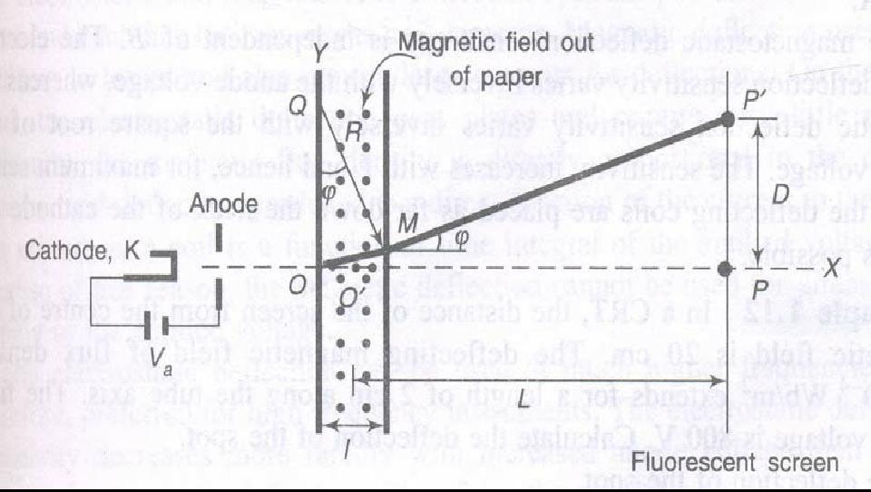
24 Fig: Magnetostatic deflection in a cathode ray Tube
25 D = LB. v a e 2m Magnetic Deflection Sensitivity: The Deflection per unit magnetic field intensity D/B is given by is called the magnetic deflection Sensitivity of the tube Which is independent of magnetic flux density B.
CATHODE RAY OSCILLOSCOPE. Basic block diagrams Principle of operation Measurement of voltage, current and frequency
 CATHODE RAY OSCILLOSCOPE Basic block diagrams Principle of operation Measurement of voltage, current and frequency 103 INTRODUCTION: The cathode-ray oscilloscope (CRO) is a multipurpose display instrument
CHAPTER 4 OSCILLOSCOPES
 CHAPTER 4 OSCILLOSCOPES 4.1 Introduction The cathode ray oscilloscope generally referred to as the oscilloscope, is probably the most versatile electrical measuring instrument available. Some of electrical
CHAPTER 3 OSCILLOSCOPES AND SIGNAL GENERATOR
 CHAPTER 3 OSCILLOSCOPES AND SIGNAL GENERATOR OSCILLOSCOPE 3.1 Introduction The cathode ray oscilloscope (CRO) provides a visual presentation of any waveform applied to the input terminal. The oscilloscope
The Cathode Ray Tube
 Lesson 2 The Cathode Ray Tube The Cathode Ray Oscilloscope Cathode Ray Oscilloscope Controls Uses of C.R.O. Electric Flux Electric Flux Through a Sphere Gauss s Law The Cathode Ray Tube Example 7 on an
OSCILLOSCOPE AND DIGITAL MULTIMETER
 Exp. No #0 OSCILLOSCOPE AND DIGITAL MULTIMETER Date: OBJECTIVE The purpose of the experiment is to understand the operation of cathode ray oscilloscope (CRO) and to become familiar with its usage. Also
Electrical and Electronic Laboratory Faculty of Engineering Chulalongkorn University. Cathode-Ray Oscilloscope (CRO)
") 2141274 Electrical and Electronic Laboratory Faculty of Engineering Chulalongkorn University Cathode-Ray Oscilloscope (CRO) Objectives You will be able to use an oscilloscope to measure voltage, frequency
2141274 Electrical and Electronic Laboratory Faculty of Engineering Chulalongkorn University Cathode-Ray Oscilloscope (CRO) Objectives You will be able to use an oscilloscope to measure voltage, frequency
CATHODE RAY OSCILLOSCOPE (CRO)
") CATHODE RAY OSCILLOSCOPE (CRO) 4.6 (a) Cathode rays CORE Describe the production and detection of cathode rays Describe their deflection in electric fields State that the particles emitted in thermionic
CATHODE RAY OSCILLOSCOPE (CRO) 4.6 (a) Cathode rays CORE Describe the production and detection of cathode rays Describe their deflection in electric fields State that the particles emitted in thermionic
Elements of a Television System
 1 Elements of a Television System 1 Elements of a Television System The fundamental aim of a television system is to extend the sense of sight beyond its natural limits, along with the sound associated
Cathode Ray Oscilloscope
 Lesson: Cathode Ray Oscilloscope Author: Dr. Arijit Chowdhuri College/ Department: Acharya Narendra Dev College, University of Delhi 1 Cathode Ray Oscilloscope (CRO) Introduction During a typical teaching-learning
THE OPERATION OF A CATHODE RAY TUBE
 THE OPERATION OF A CATHODE RAY TUBE OBJECT: To acquaint the student with the operation of a cathode ray tube, and to study the effect of varying potential differences on accelerated electrons. THEORY:
THE OPERATION OF A CATHODE RAY TUBE
 THE OPERATION OF A CATHODE RAY TUBE OBJECT: To acquaint the student with the operation of a cathode ray tube, and to study the effect of varying potential differences on accelerated electrons. THEORY:
Tutorial Cathode Rays Year 12 Physics - Module 9.3 Motors and Generators
 Tutorial 9.4.1.2 Cathode Rays Year 12 Physics - Module 9.3 Motors and Generators For use with Lesson 9.4.1 Cathode Rays 1. Identify the properties of cathode rays that indicated that they might be particles.
S op o e p C on o t n rol o s L arni n n i g n g O bj b e j ctiv i e v s
 ET 150 Scope Controls Learning Objectives In this lesson you will: learn the location and function of oscilloscope controls. see block diagrams of analog and digital oscilloscopes. see how different input
Teltron Delection Tube D
 Teltron Delection Tube D 1011119 Overview The electron-beam deflection tube is intended for investigating the deflection of electron beams in electrical and magnetic fields. It can be used to estimate
These are used for producing a narrow and sharply focus beam of electrons.
 CATHOD RAY TUBE (CRT) A CRT is an electronic tube designed to display electrical data. The basic CRT consists of four major components. 1. Electron Gun 2. Focussing & Accelerating Anodes 3. Horizontal
Using an oscilloscope - The Hameg 203-6
 Using an oscilloscope - The Hameg 203-6 What does an oscilloscope do? Setting up How does an oscilloscope work? Other oscilloscope controls Connecting a function generator Microphones audio signals and
OPERATING INSTRUCTIONS FOR SYLVANIA. Type I08 Cathode-Ray Oscilloscope. Sylvania Electric Products Inc. Industrial Apparatus. Emporium, Pennsylvania
 OPERATING INSTRUCTIONS FOR SYLVANIA Type I08 Cathode-Ray Oscilloscope Sylvania Electric Products Inc. Industrial Apparatus Plant Emporium, Pennsylvania OPERATING INSTRUCTIONS FOR Sylvania Type 08 Cathode-Ray
2.2. VIDEO DISPLAY DEVICES
 Introduction to Computer Graphics (CS602) Lecture 02 Graphics Systems 2.1. Introduction of Graphics Systems With the massive development in the field of computer graphics a broad range of graphics hardware
Computer Graphics Hardware
 Computer Graphics Hardware Kenneth H. Carpenter Department of Electrical and Computer Engineering Kansas State University January 26, 2001 - February 5, 2004 1 The CRT display The most commonly used type
The Knowledge Bank at The Ohio State University. Ohio State Engineer
 The Knowledge Bank at The Ohio State University Ohio State Engineer Title: Creators: Principles of Electron Tubes Lamoreaux, Yvonne Issue Date: 1944-03 Publisher: Ohio State University, College of Engineering
University of Utah Electrical & Computer Engineering Department ECE1050/1060 Oscilloscope
 University of Utah Electrical & Computer Engineering Department ECE1050/1060 Oscilloscope Name:, A. Stolp, 2/2/00 rev, 9/15/03 NOTE: This is a fill-in-the-blanks lab. No notebook is required. You are encouraged
INSTRUMENT CATHODE-RAY TUBE
 Instrument cathode-ray tube D14-363GY/123 INSTRUMENT CATHODE-RAY TUBE mono accelerator 14 cm diagonal rectangular flat face internal graticule low power quick heating cathode high brightness, long-life
RICHLAND COLLEGE School of Engineering Business & Technology Rev. 0 W. Slonecker Rev. 1 (8/26/2012) J. Bradbury
 J. Bradbury") RICHLAND COLLEGE School of Engineering Business & Technology Rev. 0 W. Slonecker Rev. 1 (8/26/2012) J. Bradbury INTC 1307 Instrumentation Test Equipment Teaching Unit 8 Oscilloscopes Unit 8: Oscilloscopes
RICHLAND COLLEGE School of Engineering Business & Technology Rev. 0 W. Slonecker Rev. 1 (8/26/2012) J. Bradbury INTC 1307 Instrumentation Test Equipment Teaching Unit 8 Oscilloscopes Unit 8: Oscilloscopes
3B SCIENTIFIC PHYSICS
 3B SCIENTIFIC PHYSICS Complete Fine Beam Tube System 1013843 Instruction sheet 10/15 SD/ALF If it is to be expected that safe operation is impossible (e.g., in case of visible damage), the apparatus is
Presented by: Amany Mohamed Yara Naguib May Mohamed Sara Mahmoud Maha Ali. Supervised by: Dr.Mohamed Abd El Ghany
 Presented by: Amany Mohamed Yara Naguib May Mohamed Sara Mahmoud Maha Ali Supervised by: Dr.Mohamed Abd El Ghany Analogue Terrestrial TV. No satellite Transmission Digital Satellite TV. Uses satellite
Types of CRT Display Devices. DVST-Direct View Storage Tube
 Examples of Computer Graphics Devices: CRT, EGA(Enhanced Graphic Adapter)/CGA/VGA/SVGA monitors, plotters, data matrix, laser printers, Films, flat panel devices, Video Digitizers, scanners, LCD Panels,
B. TECH. VI SEM. I MID TERM EXAMINATION 2018
 B. TECH. VI SEM. I MID TERM EXAMINATION 2018 BRANCH : COMPUTER SCIENCE ENGINEERING ( CSE ) SUBJECT : 6CS4A COMPUTER GRAPHICS & MULTIMEDIA TECHNIQUES Q 1. Write down mid point ellipse drawing algorithm.
INSTRUMENT CATHODE-RAY TUBE
 INSTRUMENT CATHODE-RAY TUBE 14 cm diagonal rectangular flat face domed mesh post-deflection acceleration improved spot quality for character readout high precision by internal permanent magnetic correction
3B SCIENTIFIC PHYSICS
 B SCIENTIFIC PHYSICS Triode S 11 Instruction sheet 1/15 ALF 1 5 7 1 Guide pin Connection pins Cathode plate Heater filament 5 Grid Anode 7 -mm plug for connecting anode 1. Safety instructions Hot cathode
PRACTICAL APPLICATIONS OF ELECTRONICS IN ANAESTHESIA. G. A. HAY Department of Medical Physics, University of Leeds
 Brit. J. Anaesth. (1955), 27, 622 PRACTICAL APPLICATIONS OF ELECTRONICS IN ANAESTHESIA 1 BY G. A. HAY Department of Medical Physics, University of Leeds PART I: BASIC PRINCIPLES IN the last twenty years
J.J. Thomson, Cathode Rays and the Electron
 Introduction Experimenters had noticed that sparks travel through rarefied (i.e. low pressure) air since the time of Franklin. The basic setup was to have two metal plates inside a glass tube. The air
UNIT IV- STORAGE AND DISPLAY DEVICES
 UNIT IV- STORAGE AND DISPLAY DEVICES OBJECTIVES: We shall learn Classification Of Recorders Magnetic disk and tape Recorders, digital plotters and printers Introduction: It is usually required to have
4.9 BEAM BLANKING AND PULSING OPTIONS
 4.9 BEAM BLANKING AND PULSING OPTIONS Beam Blanker BNC DESCRIPTION OF BLANKER CONTROLS Beam Blanker assembly Electron Gun Controls Blanker BNC: An input BNC on one of the 1⅓ CF flanges on the Flange Multiplexer
Electrical & Electronic Measurements: Class Notes (15EE36) Module-5. Display Devices
 Module-5. Display Devices") Module-5 Display Devices Syllabus: Introduction Character formats Segment displays Dot matrix displays Bar graph displays Cathode ray tubes Light emitting diodes Liquid crystal displays Nixies Incandescent
Module-5 Display Devices Syllabus: Introduction Character formats Segment displays Dot matrix displays Bar graph displays Cathode ray tubes Light emitting diodes Liquid crystal displays Nixies Incandescent
THE CATHODE -RAY OSCILLOSCOPE
 THE CATHODE -RAY OSCILLOSCOPE %ssok RRT -20 2533 N. Ashland Ave., Chicago 14, Illinois Radio Reception and Transmission LESSON RRT -20 THE CATHODE -RAY OSCILLOSCOPE CHRONOLOGICAL HISTORY OF RADIO AND
CMPE 466 COMPUTER GRAPHICS
 1 CMPE 466 COMPUTER GRAPHICS Chapter 2 Computer Graphics Hardware Instructor: D. Arifler Material based on - Computer Graphics with OpenGL, Fourth Edition by Donald Hearn, M. Pauline Baker, and Warren
Display Systems. Viewing Images Rochester Institute of Technology
 Display Systems Viewing Images 1999 Rochester Institute of Technology In This Section... We will explore how display systems work. Cathode Ray Tube Television Computer Monitor Flat Panel Display Liquid
Computer Graphics : Unit - I
 Computer Graphics Unit 1 Introduction: Computer Graphics it is a set of tools to create, manipulate and interact with pictures. Data is visualized through geometric shapes, colors and textures. Video Display
SERVICING TELEVISION VOLUME 2 G. N. PATCHETT LONDON: NORMAN PRICE (PUBLISHERS) LTD. The Cathode Ray Tube. Sawtooth Current Generators
 LTD. The Cathode Ray Tube. Sawtooth Current Generators") m 3 TELEVISION SERVICING VOLUME 2 The Cathode Ray Tube Synchronizing Separators Timebases Field Output Stage Line Output Stage Sawtooth Current Generators G. N. PATCHETT B.Sc. (Eng.)., Ph.D., C. Eng.,
m 3 TELEVISION SERVICING VOLUME 2 The Cathode Ray Tube Synchronizing Separators Timebases Field Output Stage Line Output Stage Sawtooth Current Generators G. N. PATCHETT B.Sc. (Eng.)., Ph.D., C. Eng.,
Sep 09, APPLICATION NOTE 1193 Electronic Displays Comparison
 Sep 09, 2002 APPLICATION NOTE 1193 Electronic s Comparison Abstract: This note compares advantages and disadvantages of Cathode Ray Tubes, Electro-Luminescent, Flip- Dot, Incandescent Light Bulbs, Liquid
The Venerable Triode. The earliest Triode was Lee De Forest's 1906 Audion.
 The Venerable Triode The very first gain device, the vacuum tube Triode, is still made after more than a hundred years, and while it has been largely replaced by other tubes and the many transistor types,
University of Utah Electrical Engineering Department EE1050/1060 Oscilloscope. Name:, Lab TA:
 University of Utah Electrical Engineering Department EE1050/1060 Oscilloscope Name:, Lab TA: A. Stolp, 2/2/00 rev, 9/14/00 NOTE: This is a fill-in-the-blanks lab. No notebook is required. You are encouraged
CR7000. CRT Analyzer & Restorer. Easily Test And Restore CRTs With The Most Complete Tests Available For Added Profit And Security.
 CR7000 CRT Analyzer & Restorer Easily Test And Restore CRTs With The Most Complete Tests Available For Added Profit And Security. S1 New Demands From Higher Performance CRTs Require New Analyzing Techniques
PAST EXAM PAPER & MEMO N3 ABOUT THE QUESTION PAPERS:
 EKURHULENI TECH COLLEGE. No. 3 Mogale Square, Krugersdorp. Website: www. ekurhulenitech.co.za Email: info@ekurhulenitech.co.za TEL: 011 040 7343 CELL: 073 770 3028/060 715 4529 PAST EXAM PAPER & MEMO N3
Time Varying Signals Part A Chemistry 838
 Part A Chemistry 838 Thomas V. Atkinson, Ph.D. Senior Academic Specialist Department of Chemistry Michigan State University East Lansing, MI 88 Table of Contents TABLE OF CONTENTS... TABLE OF TABLES...
INTRODUCTION TO THE APPLE" SYSTEM
 O/458 INTRODUCTION TO THE APPLE" SYSTEM An understanding of the "Apple" system of color television reception is greatly aided by the following ultra simplified review of the color television signal properties.
MODIFYING A SMALL 12V OPEN FRAME INDUSTRIAL VIDEO MONITOR TO BECOME A 525/625 & 405 LINE MULTI - STANDARD MAINS POWERED UNIT. H. Holden. (Dec.
 MODIFYING A SMALL 12V OPEN FRAME INDUSTRIAL VIDEO MONITOR TO BECOME A 525/625 & 405 LINE MULTI - STANDARD MAINS POWERED UNIT. H. Holden. (Dec. 2017) INTRODUCTION: Small open frame video monitors were made
Lecture 17 Microwave Tubes: Part I
 Basic Building Blocks of Microwave Engineering Prof. Amitabha Bhattacharya Department of Electronics and Communication Engineering Indian Institute of Technology, Kharagpur Lecture 17 Microwave Tubes:
Reading 21 ELECTRON TUBES
 Reading 21 Ron Bertrand VK2DQ http://www.radioelectronicschool.com ELECTRON TUBES One of the most significant developments of the early twentieth century was the invention of the electron tube. The British
Experiment 9A: Magnetism/The Oscilloscope
 Experiment 9A: Magnetism/The Oscilloscope (This lab s "write up" is integrated into the answer sheet. You don't need to attach a separate one.) Part I: Magnetism and Coils A. Obtain a neodymium magnet
Screens; media that use additive primaries
 Image display Display is the final stage in the image processing pipeline: Continuous scenes are acquired and digitally processed. The display process essentially converts the discrete image back to continuous
Display Devices & its Interfacing
 Display Devices & its Interfacing 3 Display systems are available in various technologies such as i) Cathode ray tubes (CRTs), ii) Liquid crystal displays (LCDs), iii) Plasma displays, and iv) Light emitting
RF Power Generation II
 RF Power Generation II Klystrons, Magnetrons and Gyrotrons Professor R.G. Carter Engineering Department, Lancaster University, U.K. and The Cockcroft Institute of Accelerator Science and Technology Scope
 Patented Nov. 14, 1950 2,529,485 UNITED STATES PATENT OFFICE 1 This invention relates to television systems and more particularly to methods of and means for producing television images in their natural
PTIK UNNES. Lecture 02. Conceptual Model for Computer Graphics and Graphics Hardware Issues
 E3024031 KOMPUTER GRAFIK E3024032 PRAKTIK KOMPUTER GRAFIK PTIK UNNES Lecture 02 Conceptual Model for Computer Graphics and Graphics Hardware Issues 2014 Learning Objectives After carefully listening this
Chapter 3 Display Components
 Chapter 3 Display Components 3.1 Backlights Backlights are one category of transillumination (in addition to edge and wedge lighting) used to provide light to nonemissive displays. Display technologies
Brown, A., Merkert, J., & Wilson, R. (2014). Build your own particle accelerator. Science in School, (30),
. Build your own particle accelerator. Science in School, (30),") Brown, A., Merkert, J., & Wilson, R. (2014). Build your own particle accelerator. Science in School, (30), 21-26. Publisher's PDF, also known as Version of record License (if available): CC BY-NC-SA Link
Brown, A., Merkert, J., & Wilson, R. (2014). Build your own particle accelerator. Science in School, (30), 21-26. Publisher's PDF, also known as Version of record License (if available): CC BY-NC-SA Link
ECE 5765 Modern Communication Fall 2005, UMD Experiment 10: PRBS Messages, Eye Patterns & Noise Simulation using PRBS
 ECE 5765 Modern Communication Fall 2005, UMD Experiment 10: PRBS Messages, Eye Patterns & Noise Simulation using PRBS modules basic: SEQUENCE GENERATOR, TUNEABLE LPF, ADDER, BUFFER AMPLIFIER extra basic:
Gechstudentszone.wordpress.com
 Unit 3: Photodiodes 3.1 Photodiodes Photodiodes are junction semiconductor light sensors that generate current or voltage when the PN junction in the semiconductor is illuminated by light of sufficient
Computer Graphics: Overview of Graphics Systems
 Computer Graphics: Overview of Graphics Systems By: A. H. Abdul Hafez Abdul.hafez@hku.edu.tr, 1 Outlines 1. Video Display Devices 2. Flat-panel displays 3. Video controller and Raster-Scan System 4. Coordinate
BLOCK DIAGRAM. Brightness Control -120V. Vertical Blanking, FBT 30V 15V. Protection TDA8172 ( IC601) Circuit -12V 12V. H/V Sync Processor
 Circuit -12V 12V. H/V Sync Processor") BLOCK DIAGRAM H.V DY CDT H- Conver gence Dynamic Focus Static Focus Auto Beam Limit Heater ( ) Screen G1 < OSD > H / V POSITION H / V SIZE SPCC TRAPIZODE PIN BALANCE PARALLELOGRAM CORNERTRAP DDC ON/OFF
BLOCK DIAGRAM H.V DY CDT H- Conver gence Dynamic Focus Static Focus Auto Beam Limit Heater ( ) Screen G1 < OSD > H / V POSITION H / V SIZE SPCC TRAPIZODE PIN BALANCE PARALLELOGRAM CORNERTRAP DDC ON/OFF
Design, Fabrication and Testing of Gun-Collector Test Module for 6 MW Peak, 24 kw Average Power, S-Band Klystron
 Available online www.ejaet.com European Journal of Advances in Engineering and Technology, 2014, 1(1): 11-15 Research Article ISSN: 2394-658X Design, Fabrication and Testing of Gun-Collector Test Module
Monitor and Display Adapters UNIT 4
 Monitor and Display Adapters UNIT 4 TOPIC TO BE COVERED: 4.1: video Basics(CRT Parameters) 4.2: VGA monitors 4.3: Digital Display Technology- Thin Film Displays, Liquid Crystal Displays, Plasma Displays
? Me ???????? ?????? & > Dec. 14, ??? 2,455,992 ???.. ????? T. T. GOLDSMITH, Jr., ET AL CATHODE-RAY TUBE AMUSEMENT DEVICE. Filed Jan, 25, 1947
 Dec. 14, 1948. Filed Jan, 25, 1947 T. T. GOLDSMITH, Jr., ET AL CATHODE-RAY TUBE AMUSEMENT DEVICE 2,455,992 $?* do??? (TD S Y O s??????????? & > 8+ N zz +aosz No.O2 ---- g s S ÀY vr N???..??????? Me V)??
decodes it along with the normal intensity signal, to determine how to modulate the three colour beams.
 Television Television as we know it today has hardly changed much since the 1950 s. Of course there have been improvements in stereo sound and closed captioning and better receivers for example but compared
Display Technologies CMSC 435. Slides based on Dr. Luebke s slides
 Display Technologies CMSC 435 Slides based on Dr. Luebke s slides Recap: Transforms Basic 2D Transforms: Scaling, Shearing, Rotation, Reflection, Composition of 2D Transforms Basic 3D Transforms: Rotation,
KLYSTRON GUN ARCING AND MODULATOR PROTECTION
 SLAC-PUB-10435 KLYSTRON GUN ARCING AND MODULATOR PROTECTION S.L. Gold Stanford Linear Accelerator Center (SLAC), Menlo Park, CA USA Abstract The demand for 500 kv and 265 amperes peak to power an X-Band
IMPROVEMENTS IN THE CONSTRUCTION OF CATHODE.RAY TUBES
 180 PHILIPS TECHNICAL REVIEW 1947 IMPROVEMENTS IN THE CONSTRUCTION OF CATHODE.RAY TUBES by J. de GIER and A. P. van ROOY. 621.385,832 The use of a fiat glass base with chrome iron pins has long been known
Basically we are fooling our brains into seeing still images at a fast enough rate so that we think its a moving image.
 Basically we are fooling our brains into seeing still images at a fast enough rate so that we think its a moving image. The formal definition of a Moving Picture... A sequence of consecutive photographic
Reading. Display Devices. Light Gathering. The human retina
 Reading Hear & Baker, Computer graphics (2 nd edition), Chapter 2: Video Display Devices, p. 36-48, Prentice Hall Display Devices Optional.E. Sutherland. Sketchpad: a man-machine graphics communication
UNIT-3 Part A. 2. What is radio sonde? [ N/D-16]
![UNIT-3 Part A. 2. What is radio sonde? [ N/D-16]](/thumbs/88/116973079.jpg "UNIT-3 Part A. 2. What is radio sonde? [ N/D-16]") UNIT-3 Part A 1. What is CFAR loss? [ N/D-16] Constant false alarm rate (CFAR) is a property of threshold or gain control devices that maintain an approximately constant rate of false target detections
UNIT-3 Part A 1. What is CFAR loss? [ N/D-16] Constant false alarm rate (CFAR) is a property of threshold or gain control devices that maintain an approximately constant rate of false target detections
A History of the Analog Cathode Ray Oscilloscope
 1 A History of the Analog Cathode Ray Oscilloscope by OLIVER DALTON and LIONEL KREPS CONTENTS 1.Introduction 3 Cathode Ray Oscilloscope definition 3 A History of the Cathode Ray Oscilloscope 3 2 Chapter
PanelView 1400e CRT Maintenance
 Release Note PanelView 1400e CRT Maintenance Maximizing the life of your PanelView 1400e, CRT Terminals To maximize the life of a CRT, the following is strongly recommended: Adjust the external brightness
4. ANALOG TV SIGNALS MEASUREMENT
 Goals of measurement 4. ANALOG TV SIGNALS MEASUREMENT 1) Measure the amplitudes of spectral components in the spectrum of frequency modulated signal of Δf = 50 khz and f mod = 10 khz (relatively to unmodulated
MODULE I MCA COMPUTER GRAPHICS ADMN APPLICATIONS OF COMPUTER GRAPHICS
 MODULE 1 1. APPLICATIONS OF COMPUTER GRAPHICS Computer graphics is used in a lot of areas such as science, engineering, medicine, business, industry, government, art, entertainment, advertising, education
16 Stage Bi-Directional LED Sequencer
 16 Stage Bi-Directional LED Sequencer The bi-directional sequencer uses a 4 bit binary up/down counter (CD4516) and two "1 of 8 line decoders" (74HC138 or 74HCT138) to generate the popular "Night Rider"
Slides on color vision for ee299 lecture. Prof. M. R. Gupta January 2008
 Slides on color vision for ee299 lecture Prof. M. R. Gupta January 2008 light source Color is an event??? human perceives color human cones respond: 1 w object has absorption spectra and reflectance spectra
Comp 410/510. Computer Graphics Spring Introduction to Graphics Systems
 Comp 410/510 Computer Graphics Spring 2018 Introduction to Graphics Systems Computer Graphics Computer graphics deals with all aspects of 'creating images with a computer - Hardware (PC with graphics card)
Tutorial: Trak design of an electron injector for a coupled-cavity linear accelerator
 Tutorial: Trak design of an electron injector for a coupled-cavity linear accelerator Stanley Humphries, Copyright 2012 Field Precision PO Box 13595, Albuquerque, NM 87192 U.S.A. Telephone: +1-505-220-3975
Part 1: Introduction to computer graphics 1. Describe Each of the following: a. Computer Graphics. b. Computer Graphics API. c. CG s can be used in
 Part 1: Introduction to computer graphics 1. Describe Each of the following: a. Computer Graphics. b. Computer Graphics API. c. CG s can be used in solving Problems. d. Graphics Pipeline. e. Video Memory.
Reading. Displays and framebuffers. Modern graphics systems. History. Required. Angel, section 1.2, chapter 2 through 2.5. Related
 Reading Required Angel, section 1.2, chapter 2 through 2.5 Related Displays and framebuffers Hearn & Baker, Chapter 2, Overview of Graphics Systems OpenGL Programming Guide (the red book ): First four
L14 - Video. L14: Spring 2005 Introductory Digital Systems Laboratory
 L14 - Video Slides 2-10 courtesy of Tayo Akinwande Take the graduate course, 6.973 consult Prof. Akinwande Some modifications of these slides by D. E. Troxel 1 How Do Displays Work? Electronic display
Reading. 1. Displays and framebuffers. History. Modern graphics systems. Required
 Reading Required 1. Displays and s Angel, pp.19-31. Hearn & Baker, pp. 36-38, 154-157. OpenGL Programming Guide (available online): First four sections of chapter 2 First section of chapter 6 Optional
Part 1: Introduction to Computer Graphics
 Part 1: Introduction to Computer Graphics 1. Define computer graphics? The branch of science and technology concerned with methods and techniques for converting data to or from visual presentation using
3. Displays and framebuffers
 3. Displays and framebuffers 1 Reading Required Angel, pp.19-31. Hearn & Baker, pp. 36-38, 154-157. Optional Foley et al., sections 1.5, 4.2-4.5 I.E. Sutherland. Sketchpad: a man-machine graphics communication
High-resolution screens have become a mainstay on modern smartphones. Initial. Displays 3.1 LCD
 3 Displays Figure 3.1. The University of Texas at Austin s Stallion Tiled Display, made up of 75 Dell 3007WPF LCDs with a total resolution of 307 megapixels (38400 8000 pixels) High-resolution screens
Q1. Do LED lights burn out?
 Here are answers to your LED lighting Frequently Asked Questions. We hope this page is helpful and informative. Be sure to come back from time to time as we continually add to this page to reflect the
PERFORMANCE SPECIFICATION SHEET ELECTRON TUBE, CATHODE RAY TYPE 7AGP19
 INCH-POUND MIL-PRF-1/1178E 22 July 1999 SUPERSEDING MIL-E-1/1178D(EC) 23 December 1976 PERFORMANCE SPECIFICATION SHEET ELECTRON TUBE, CATHODE RAY TYPE 7AGP19 This specification is approved for use by all
NAPIER. University School of Engineering. Advanced Communication Systems Module: SE Television Broadcast Signal.
 NAPIER. University School of Engineering Television Broadcast Signal. luminance colour channel channel distance sound signal By Klaus Jørgensen Napier No. 04007824 Teacher Ian Mackenzie Abstract Klaus
ANTENNAS, WAVE PROPAGATION &TV ENGG. Lecture : TV working
 ANTENNAS, WAVE PROPAGATION &TV ENGG Lecture : TV working Topics to be covered Television working How Television Works? A Simplified Viewpoint?? From Studio to Viewer Television content is developed in
The Use of an Electron Microchannel as a Self-Extracting and Focusing Plasma Cathode Electron Gun
 The Use of an Electron Microchannel as a Self-Extracting and Focusing Plasma Cathode Electron Gun S. CORNISH, J. KHACHAN School of Physics, The University of Sydney, Sydney, NSW 6, Australia Abstract A
Television brian egan isnm 2004
 Introduction Mechanical early developments. Electrical how it works. Digital advantages over analogue. brian egan isnm Mechanical television First televisions were mechanical based on revolving disc, first
 THE OSCILLOSCOPE AND SPECTRUM ANALYZER http://www.infodotinc.com/neets/book16/71.htm Page 1 of 5 Order this information in Print Order this information on CD-ROM D Click here to make tpub.com your Home
Lecture Flat Panel Display Devices
 Lecture 13 6.111 Flat Panel Display Devices Outline Overview Flat Panel Display Devices How do Displays Work? Emissive Displays Light Valve Displays Display Drivers Addressing Schemes Display Timing Generator
Effect on Beam Current on varying the parameters of BFE and Control Anode of a TWT Electron Gun
 International Journal of Photonics. ISSN 0974-2212 Volume 7, Number 1 (2015), pp. 1-9 International Research Publication House http://www.irphouse.com Effect on Beam Current on varying the parameters of
This work was supported by FINEP (Research and Projects Financing) under contract
 under contract") MODELING OF A GRIDDED ELECTRON GUN FOR TRAVELING WAVE TUBES C. C. Xavier and C. C. Motta Nuclear & Energetic Research Institute, São Paulo, SP, Brazil University of São Paulo, São Paulo, SP, Brazil Abstract
MODELING OF A GRIDDED ELECTRON GUN FOR TRAVELING WAVE TUBES C. C. Xavier and C. C. Motta Nuclear & Energetic Research Institute, São Paulo, SP, Brazil University of São Paulo, São Paulo, SP, Brazil Abstract
User's Manual. Rev 1.0
 User's Manual Rev 1.0 Digital TV sales have increased dramatically over the past few years while the sales of analog sets are declining precipitously. First quarter of 2005 has brought the greatest volume
CHAPTER 9. Actives Devices: Diodes, Transistors,Tubes
 CHAPTER 9 Actives Devices: Diodes, Transistors,Tubes 1 The electrodes of a semiconductor diode are known as anode and cathode. In a semiconductor diode, electrons flow from cathode to anode. In order for
INTRODUCTION. The purpose of this report is to describe the present method employed in
 M/123.1 November 3, 1952 INTRODUCTION The purpose of this report is to describe the present method employed in designing and aligning a color television receiver incorporating the Philco Apple Tube. It
Design of VGA Controller using VHDL for LCD Display using FPGA
 International OPEN ACCESS Journal Of Modern Engineering Research (IJMER) Design of VGA Controller using VHDL for LCD Display using FPGA Khan Huma Aftab 1, Monauwer Alam 2 1, 2 (Department of ECE, Integral