Troubleshooting CS800/LC900 Bikes
|
|
|
- Christina Anderson
- 5 years ago
- Views:
Transcription
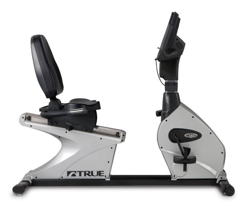
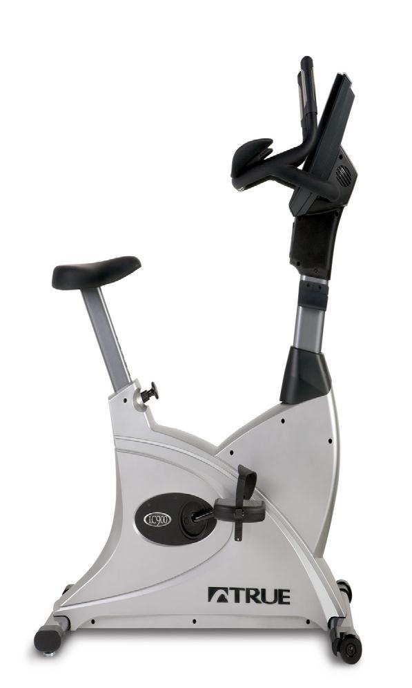
1 Troubleshooting CS800/LC900 Bikes

2 CS800/900LC Bike Troubleshooting Entering the Maintenance Mode 15 Touch Screen: The Maintenance Mode is designed to help the tech determine certain faults in the upper control boards and feedback from the brake system. Press and hold the top left corner of screen until the True emblem will begin to flash after 4 seconds. Press and hold Manual Workout Button to reveal list of options 1. Configure (Displays the current model setup) 2. Calibration (Primary use on treadmills, can see RPM here) 3. Diagnostics (Used only on treadmills) 4. Production Tests (Test the brake system) 5. Utilities (Install software, TV tuner setup, touch screen setup) 2

3 CS800, LC900 Bike Self Generating (Electromagnetic Brake) LCD 2 Window Press the CLEAR ENTRY button until the display blinks then immediately press and hold the ENTER button until ENTER PASSCODE appears. Press then ENTER. The word Production Test will appear. Pressing the enter button will scroll through a menu of items and are as follows. EPROM Test. (Shows SW Version) Key Test (Test Keys) Display Test (Test Display) Control Test (Not Used By Service) HR Test (Check Polar/Contact) Vart Test (Not Used By Service) A/D Channels (Not Used By Service) Brake Pedal RPM (RPM Read from brake voltage) Watch Dog Test (Exits Production Test) BV Set Up (Program Entertainment) See Instructions.
4 CS800, LC900 Bike Self Generating (Electromagnetic Brake) LCD 2 Window Manager Mode: Press the CLEAR ENTRY button until the display blinks then immediately press and hold the ENTER button until ENTER PASSCODE appears. Press then ENTER. The word configure will appear. Pressing the enter button will scroll through a menu of items and are as follows. Language (English, Spanish, German, French) Units (English, Metric) Max Time (45) Default Time (30) Pause Time (15 Sec) Pulse Priority (Contact) Operation Mode (Normal) Man Operation (Mets) Sound Enable (On/Off) Smart Start Enable (On/Off) Happy Mode (On/Off) C Safe Enable (On/Off) C Safe Auto (On/Off) Default Weight (150) Cal Slope (0.6666) Cal Offset (0.0000) Power Factor (1.0000) Massage Backlight (15) Matrix Backlight (32) Message Contrast (35) Matrix Contrast (45) Factory Defaults (Off) 4
5 CS800, LC900 Bike Self Generating (Electromagnetic Brake) LCD 2 Window Press the CLEAR ENTRY button until the display blinks then immediately press and hold the ENTER button until ENTER PASSCODE appears. Press then ENTER. The word Production Test will appear. Pressing the enter button will scroll through a menu of items and are as follows. Configure Model Gear Ratio Language Units Max Time Default Time Pause Time Pulse Priority OP Mode Man Operation Sound Smart Start Happy Mode C Safe Enable C Safe Auto Def Weight Cal Slope Cal Offset Pwr Factor Mess Backlight Matrix Backlight Factory Default
6 Console Display Will Not Advance/Resets/ No RPM Touch Screen CS800/LC900 Bike Upon starting any bike program, if the screen will not advance, asks if you would like to end workout, RPM signal is not being detected at the upper console, check the following: 1. Starting from the console assembly check to make sure the console data cable is plugged in firmly to the console and into the lower board and check for disconnections/cable damage in the pedestal neck. 2. If damage is found and cable has no continuity replace cable. If cable tests good with a meter proceed to the next step. 3. Check to make sure there is AC voltage at the lower board from all three phases from the generator. The white cable on the generator cable carries the RPM voltage. 4. If there is no AC voltage on the white cable check the continuity of the cable. If there is no continuity replace the generator cable. If there is continuity proceed to the next step. 5. Check the voltage across all three phases of the generator. If there is not voltage when the generator is moving across all three phases replace the generator. If there is voltage across 3 phases replace lower board. 6


7 Full Resistance When Pedaling Begins 1. Disconnect the console data cable on the upper panel. If there is still full resistance, continue to the next step. If the full resistance condition subsides, replace upper console. 2. Disconnect the console cable on the lower controller and retest for full resistance. 3. If full resistance stops, replace the console cable. 4. If full resistance continues, disconnect the generator cable on the controller and retest for full resistance. 5. If full resistance stops, replace the controller. 6. If full resistance continues, disconnect the generator cable from the generator assembly. 7. If full resistance stops, replace the generator cable. 8. If full resistance continues, replace the generator assembly. 7
 on the upper console. Voltage should increase as resistance increases. Check for same at the lower board also.")
8 No Resistance 1. Leaving the console cable plugged into the upper console, probe the console cable on pin 9 (Control Out) and pin 4 (GND) for Volts DC. Press the workload up button (+) on the upper console. Voltage should increase as resistance increases. Check for same at the lower board also. (If there is voltage at the upper and not the lower board replace the data cable) 2. If the voltage does not increase, replace the upper console. 3. If the voltage increases, check the coil cable for Volts DC on the lower board, with the cable connected to the controller. Dig through the glue and probe both cables. Voltage should increase as resistance is increased. 4. If there is no increase in voltage at the controller, replace the controller. 5. If there is a voltage increase at the controller, probe the coil cable connector at the base of the generator for DC Volts. Voltage should increase as resistance command increases. Note: You must leave the coil cable connected and probe the back of the connector to get an accurate reading. 6. If there is no voltage increase at the coil cable connector, replace the coil cable. 7. If there is voltage increase at the coil cable connector, replace the generator assembly. 8
9 CS800/900LC Bike No Console Display Touch Screen The touch screen console requires a DC power supply to operate. follow the steps below to determine the component issue. 1. Disconnect the 2 conductor power cable (red and black) at the upper board and probe for 12 VDC 2. If you test 12 VDC at the upper, replace the console. 3. If there is not 12 VDC at the upper probe for 12 VDC at the power supply under shroud. 4. If there is 12 VDC at the power supply replace the intermediate power cable. 5. If there is no 12 VDC, check for 120 VAC coming in to the power supply. If there is 120 VAC replace the power supply. 9
10 No Power/Console Display Not Powering Up 2 Window Display CS800/LC900 Bike 1. Disconnect the console cable from the upper console. 2. Check for 12 VDC on pins 1 (+12V), and 4 (GND), and check for 12 VDC on pins 2 (+12V), and 4 (GND). 11 &12= 12v, 9 & 10= gnd 3. If 12 VDC is found across both pins, replace the upper console. 4. If 12 VDC is not found, check for continuity on the console cable. 5. If there is no continuity, replace the console cable. 6. If there is continuity on the console cable, locate the VCON LED and GEN+ LED on controller. 7. If GEN+ LED is illuminated when pedaling and the VCON LED is not lit, replace the controller. 8. If GEN + LED is not illuminated, check for Volts AC from the generator cable (black and white wires) connected to J1 on the controller. The reading should be approximately Volts AC at slow speed. 10

, before maintenance, (unless instructed to power equipment as part of a test procedure or an electrical check).")
11 Warning This True Fitness Technology Inc. equipment contains hazardous voltages and high speed moving parts. Contact with these hazards will potentially cause death, serious personal injury or may damage equipment. Only qualified personnel, (as outlined below), should install, operate and maintain this equipment. Always properly ground equipment and lock out electric power, (de-energize), before maintenance, (unless instructed to power equipment as part of a test procedure or an electrical check). True recommends the use of safety glasses when servicing equipment. Using non-specified / unauthorized parts or components to repair equipment, or tampering with safety devices/systems will result in dangerous conditions which can potentially cause damage to equipment, severe personal injury or death. Take note of and follow all safety instructions contained in this manual. 9. If there is voltage on the generator cable, replace the controller. 10. If there is no voltage on the generator cable, test for continuity on the generator cable. 11. If the continuity test fails on the generator cable, replace the generator cable. 12. If the generator cable has continuity, replace the generator assembly. TrueFitness.com 11
12 I pod will not connect Remove the 2 Philips screws that attach the I Pod plate to the console. 12
13 I pod will not connect Unplug all of the cables that are attached to the I pod Faceplate. 13

14 I pod will not connect Remove the I Pod cable from faceplate and unplug from the console. Replace new cable in reverse order. Reinstall the faceplate. 14

15 Headphone Jack Has Static/No Sound In the event that the headphones when plugged in to The console create static, intermittent sound, or no Sound at all replace the headphone jack according to the procedure below. Remove the 2 Philips screws that attach the I Pod plate to the console. 15
16 Headphone Jack Has Static/No Sound Unplug all of the cables that are attached to the I pod Faceplate. 16

17 Headphone Jack Has Static/No Sound Remove the 2 Phillips screws that attach the headphone jack to the I pod plate. Install the new headphone jack and test 17

18 LCD 2 Window Displays Software Installation Instructions for the Bike 2 Window LCD Displays First check and record the current software version by pressing and holding the CLEAR ENTRY button while pedaling. When the screen blanks out press and hold ENTER until enter code appears, Press then press ENTER and then START to display the software version. Insert the USB Storage Device into the console. Press and hold Clear/Entry while pedaling until screen blanks out. Immediately press and hold the channel up/fwd button until code update appears on screen. Press Enter and the software will upload to the console When screen returns to normal mode remove the USB Storage Device from the console and verify the new software uploaded in the unit.
19 Broadcastvision TV Preset Programming Instructions 2 Window Display for TRUE FITNESS Treadmills and Bikes NOTES: Bikes Only: Because this is a self-generating product, you must continue to pedal during this procedure. Treadmills: Plug in treadmill and flip power switch ON. Text messages shown on display are indicated below in QUOTATION MARKS. Key names are indicated below in BOLD CAPS. Broadcastvision is abbreviated BV below. TV Programming 1.Note the number of TV s visible in the facility room that you intend to program audio setup for. ENTERING TEST MODE (NOTE: STEPS 1 4 are time dependent. Press keys quickly) Step 2. Press and hold the CLEAR ENTRY key until display blanks, then quickly proceed to STEP 3. Step 3. Press and hold the ENTER key until you hear a beep, then quickly proceed to STEP 4. PASS CODE will display. Step 4. Press the following number keys in sequence and press the ENTER key. CONSOLE VERSION will display. ENTERING BV SETUP MODE 1.Press the ENTER key repeatedly until BV SETUP is displayed. 2.Press the START key on center pod to enter BV SETUP mode. ENTER PROG MODE will display. 3.Press the 2 key to select BV Series 2. LOAD BV SERIES 2 will display. NOTE: These Displays are optimally designed to work with Broadcastvision transmitters which should be part of this wireless installation. If non-broadcastvision transmitters are being used, one should try at this point of these instructions to press 4 to LOAD BV SERIES 4 for Mye / Fantaay transmitters or press 8 to LOAD BV SERIES 8 for Cardio Theater LCS transmitters or press 9 to LOAD BV SERIES 9 for Cardio Theater xtv transmitters. This may allow for reception under these circumstances.
20 PROGRAMMING TV PRESET CHANNEL LOCATIONS Plug stereo headphones into console and wear headphones for remaining steps of TV Programming. Programming the first preset channel If you clearly hear the TV audio that want to program in the first preset channel location, then press the MUTE key to save it. SAVE FREQ TO CHAN will display. If you do not hear the TV audio that you want, press the VOL Λ key to select the desired TV transmitter audio, and then press the MUTE key to save it. NOTE: The order in which TV transmitter audio channels are saved determines their displayed TV channel number when in normal display mode. The first TV transmitter audio channel saved will become TV CHAN 1, and the next TV transmitter audio channel saved will become TV CHAN 2, etc. PROGRAMMING THE NEXT TV PRESET CHANNEL (and remaining channels) Repeatedly press the VOL Λ key until you hear the TV audio that you want to program, and then press the MUTE key to save it. Use this same procedure to program all other preset channel locations for all remaining visible TV s. If you accidently save TV audio to the wrong preset channel location, press the SOURCE key to unsave it. UNSAVE FREQ IN CH will display. Then repeat STEP 9 for desired TV audio source. To exit programming mode, Press and hold the CLEAR ENTRY key until display blanks and resets to normal operate mode. TV Programming is now complete. Should you need technical assistance for your TRUE Fitness product contact TRUE Fitness Technical Support at

21 Software Installation for Touch Screen 21

22 Software Installation for Touch Screen 22
23 Software Installation for Touch Screen 23
apple Service Source Apple Cinema HD Display 23" LCD (ADC) 11 April Apple Computer, Inc. All rights reserved.
 11 April Apple Computer, Inc. All rights reserved.") apple Service Source Apple Cinema HD Display 23" LCD (ADC) 11 April 2003 2003 Apple Computer, Inc. All rights reserved. apple Service Source Take Apart Apple Cinema HD Display 23" LCD (ADC) 2003 Apple
apple Service Source Apple Cinema HD Display 23" LCD (ADC) 11 April 2003 2003 Apple Computer, Inc. All rights reserved. apple Service Source Take Apart Apple Cinema HD Display 23" LCD (ADC) 2003 Apple
apple Service Source Apple Studio Display 17" LCD (ADC) Updated 6 Decenber Apple Computer, Inc. All rights reserved.
 Updated 6 Decenber Apple Computer, Inc. All rights reserved.") apple Service Source Apple Studio Display 17" LCD (ADC) Updated 6 Decenber 2004 2003 Apple Computer, Inc. All rights reserved. apple Service Source Take Apart Apple Studio Display 17" LCD (ADC) 2003 Apple
apple Service Source Apple Studio Display 17" LCD (ADC) Updated 6 Decenber 2004 2003 Apple Computer, Inc. All rights reserved. apple Service Source Take Apart Apple Studio Display 17" LCD (ADC) 2003 Apple
USER MANUAL. 27 Full HD Widescreen LED Monitor L270E
 USER MANUAL 27 Full HD Widescreen LED Monitor L270E TABLE OF CONTENTS 1 Getting Started 2 Control Panel/ Back Panel 3 On Screen Display 4 Technical Specs 5 Care & Maintenance 6 Troubleshooting 7 Safety
LS 6.0R SERVICE MANUAL
 LS 6.0R SERVICE MANUAL 1 TABLE OF CONTENTS CHAPTER 1: SERIAL NUMBER LOCATION CHAPTER 2: CONSOLE OVERLAY AND WORKOUT DESCRIPTION 2.1 Console Description 2.2 Display Windows Description 2.3 Getting Started
Evolution Digital HD Set-Top Box Important Safety Instructions
 Evolution Digital HD Set-Top Box Important Safety Instructions 1. Read these instructions. 2. Keep these instructions. 3. Heed all warnings. 4. Follow all instructions. 5. Do not use this apparatus near
(E-UB) UPRIGHT BIKE INSTALLATION INSTRUCTIONS
 UPRIGHT BIKE INSTALLATION INSTRUCTIONS") (E-UB) UPRIGHT BIKE INSTALLATION INSTRUCTIONS E-UB Upright Bike 4 620-7922 Rev B GENERAL Before using this product, it is essential to read ALL installation Instructions and this ENTIRE operations manual;
(E-UB) UPRIGHT BIKE INSTALLATION INSTRUCTIONS E-UB Upright Bike 4 620-7922 Rev B GENERAL Before using this product, it is essential to read ALL installation Instructions and this ENTIRE operations manual;
PLL2210MW LED Monitor
 PLL2210MW LED Monitor USER'S GUIDE www.planar.com Content Operation Instructions...1 Safety Precautions...2 First Setup...3 Front View of the Product...4 Rear View of the Product...5 Quick Installation...6
USER MANUAL. 27 Full HD Widescreen LED Monitor L27ADS
 USER MANUAL 27 Full HD Widescreen LED Monitor L27ADS TABLE OF CONTENTS 1 Getting Started 2 Control Panel/ Back Panel 3 On Screen Display 4 Technical Specs 5 Care & Maintenance 6 Troubleshooting 7 Safety
Welcome to W light up your life
 USER GUIDE 1 Welcome to light up your life Dear Vision Communications Customer, Thank you for choosing LightWave TV from Vision. LightWave TV will open a whole new world of TV entertainment for you and
Platinum Tools Inc. All rights reserved. 5/12 Voice, Data, Video + Length GENERAL SPECIFICATIONS WARNINGS
 Voice, Data, Video + Length Instruction Sheet: P/N T9 GENERAL SPECIFICATIONS The Platinum Tools, VDV MapMaster.0 is a portable voice-data-video cable tester with length measurement. It tests and troubleshoots
USER MANUAL FOR THE ANALOGIC GAUGE FIRMWARE VERSION 1.1
 by USER MANUAL FOR THE ANALOGIC GAUGE FIRMWARE VERSION 1.1 www.aeroforcetech.com Made in the USA! WARNING Vehicle operator should focus primary attention to the road while using the Interceptor. The information
Delvcam DELV-HD7-4K User Guide
 Delvcam DELV-HD7-4K User Guide 7" 4K Compatible 1080P Camera Top Monitor with Audio Meter IMPORTANT SAFETY INSTRUCTIONS Read manual before using this product. Keep manual for future reference. Do not place
Owners SW-LCD 2.0 Manual & Specifications
 Owners SW-LCD 2.0 Manual & Specifications Contents 1. Preface. 19 2. Appearance and Size.20 2.1 Material and Color 20 2.2 Display Size and Installation Size 20 3. Function Summary and Button Definition
USERS MANUAL GR ONE 300 GR ONE 700 GR ONE 1400
 USERS MANUAL GR ONE 300 GR ONE 700 GR ONE 1400 PURE SOUND USER MANUAL PURPOSE This user manual is dedicated to the use of the bass amplifiers GR-ONE 700, GR-ONE700x2 and GR-ONE 300. The manual includes
HD Digital Set-Top Box Quick Start Guide
 HD Digital Set-Top Box Quick Start Guide Eagle Communications HD Digital Set-Top Box Important Safety Instructions WARNING TO REDUCE THE RISK OF FIRE OR ELECTRIC SHOCK, DO NOT EXPOSE THIS PRODUCT TO RAIN
Rain+Birdt. Landscape Irrigation & Maintenance Remote System. Quick Start Guide 4.00 F G H K 9X. c n. System Components
 Rain+Birdt Landscape Irrigation & Maintenance Remote System Quick Start Guide 4.00 D System Components A Transmitter (TX) B Receiver (RX) C Quick Connect (QC) 6-Pin Quick Connect (QC) for use with ESP-Modular
DVH-1019 MK2 User Manual PULL
 DVH-1019 MK2 User Manual PULL Safety Rules WARNING Read all instructions. Failure to follow all instructions listed below may result in electric shock, fire and/or serious injury. The term electrical device,as
USER MANUAL. 28" 4K Ultra HD Monitor L28TN4K
 USER MANUAL 28" 4K Ultra HD Monitor L28TN4K TABLE OF CONTENTS 1 Getting Started 2 Control Panel/ Back Panel 3 On Screen Display 4 Technical Specs 5 Care & Maintenance 6 Troubleshooting 7 Safety Info &
USER MANUAL. 27" 2K QHD LED Monitor L27HAS2K
 USER MANUAL 27" 2K QHD LED Monitor L27HAS2K TABLE OF CONTENTS 1 Getting Started 2 Control Panel/ Back Panel 3 On Screen Display 4 Technical Specs 5 Troubleshooting 6 Safety Info & FCC warning 1 GETTING
NewScope-7A Operating Manual
 2016 SIMMCONN Labs, LLC All rights reserved NewScope-7A Operating Manual Preliminary May 13, 2017 NewScope-7A Operating Manual 1 Introduction... 3 1.1 Kit compatibility... 3 2 Initial Inspection... 3 3
User Manual CC DC 24 V 5A. Universal Control Unit UC-1-E. General Information SET. Universal Control Unit UC-1 Of Central Lubrication PAUSE CONTACT
 Universal Control Unit UC-1-E User Manual General Information Universal Control Unit UC-1 Of Central Lubrication CC DC 24 V 5A / M 15 SL /MK 31 M Z 30 General Information Contents Universal Control Unit
AUTOMATIC VIDEO LOSS A/B SWITCH
 CG-X AUTOMATIC VIDEO LOSS A/B SWITCH INSTRUCTION BOOK IB647502 TABLE OF CONTENTS DESCRIPTION 2 MOUNTING INSTRUCTIONS 3 HOW TO CABLE THE CG-X 3 POWER SUPPLY INSTALLATION 3 OPERATION 3 CARE AND MAINTENANCE
END USER MANUAL DAS-M44HD-R
 END USER MANUAL DAS-M44HD-R Warnings: Important Safety Instructions and Caution Please read all of these instructions regarding your unit and retain them for future reference Read this manual fully and
Field Service Procedure Replacement GACP Control Panel Kit, ST24
 1. Brief Summary: Troubleshooting document for diagnosing a fault with and replacing the Graphic Antenna Control Panel (GACP) for the ST24 antenna. 2. Checklist: Verify Power to the GACP Verify Communications
Magnetic Rower. Manual Jetstream JMR-5000
 Magnetic Rower Manual Jetstream JMR-5000 EXPLODED DRAWING PARTS LIST Assembly front stabilizer with main frame Step 1. Secure the front stabilizer (A2) and main frame(a1) using carriage bolt(1) & Nut(2).
INSTRUCTIONAL MANUAL FOR LCD ZOOM MICROSCOPE
 INSTRUCTIONAL MANUAL FOR LCD ZOOM MICROSCOPE ? 8 LCD Screen? 10.4 LCD Screen LCD Zoom Microscope Instruction Manual Please read the Instruction Manual carefully before installation and keep it for future
Manual. Simrad IS80 Heading Repeater HR80. English
 Manual Simrad IS80 Heading Repeater HR80 English www.simrad-yachting.com A brand by Navico - Leader in Marine Electronics Manual Simrad IS80 Heading Repeater HR80 English Document no: 20223194 Revision:
DH5e-V2. Delta 5 On-Camera 4K HDMI Monitor with 3D LUTs. Quick Start Guide. What s Included
 DH5e-V2 Quick Start Guide Delta 5 On-Camera 4K Monitor with 3D LUTs What s Included 1 x DH5e-V2 Monitor 1 x L Series Battery Plate 1 x AC Adapter 1 x Screen Cleaning Wipe 1 x Screen Protection Film 1 x
2013, 2014 Hewlett-Packard Development Company, L.P.
 User Guide 2013, 2014 Hewlett-Packard Development Company, L.P. The only warranties for HP products and services are set forth in the express warranty statements accompanying such products and services.
OWNER S MANUAL MOTORIZED 7 WIDE TFT LCD COLOR MONITOR CNT-701
 OWNER S MANUAL PW MOTORIZED 7 WIDE TFT LCD COLOR MONITOR CNT-701 ANY CHANGES OR MODIFICATIONS IN CONSTRUCTION OF THIS UNIT DEVICE WHICH IS NOT APPROVED BY THE PARTY RESPONSIBLE FOR COMPLIACE COULD VOID
DSIM-GI Installation Guide Revision P
 Installation Guide Revision P 1. Quick Start Instructions for Single Pilot AGC Operatation 1. With the ADU jumper in Auto position, turn ADU pot to MIN amplifier output level. Then place the ADU jumper
AES-402 Automatic Digital Audio Switcher/DA/Digital to Analog Converter
 Broadcast Devices, Inc. AES-402 Automatic Digital Audio Switcher/DA/Digital to Analog Converter Technical Reference Manual Broadcast Devices, Inc. Tel. (914) 737-5032 Fax. (914) 736-6916 World Wide Web:
USER MANUAL Full HD Widescreen LED Monitor L236VA
 USER MANUAL 23.6 Full HD Widescreen LED Monitor L236VA TABLE OF CONTENTS 1 Getting Started 2 Control Panel/ Back Panel 3 On Screen Display 4 Technical Specs 5 Care & Maintenance 6 Troubleshooting 7 Safety
RD RACK MOUNT DIMMER OWNERS MANUAL VERSION /09/2011
 RD - 122 RACK MOUNT DIMMER OWNERS MANUAL VERSION 1.3 03/09/2011 Page 2 of 14 TABLE OF CONTENTS UNIT DESCRIPTION AND FUNCTIONS 3 POWER REQUIREMENTS 3 INSTALLATION 3 PLACEMENT 3 POWER CONNECTIONS 3 OUTPUT
12months. on-site warranty. DZE ELECTRONIC PRESSURE SWITCH for detection of overload per EN 81 2 featuring two adjustable switching points
 BUCHER PRODUCTS AVAILABLE FROM HYDRATEC DZE ELECTRONIC PRESSURE SWITCH for detection of overload per EN 81 2 featuring two adjustable switching points 12months on-site warranty All our work comes with
LCD MONITOR. quick start guide P2070,P2270,P2370,P2070G,P2270G,P2370G
 LCD MONITOR quick start guide P2070,P2270,P2370,P2070G,P2270G,P2370G ii Introduction Package Contents Please make sure the following items are included with your monitor. If any items are missing, contact
AES-404 Digital Audio Switcher/DA/Digital to Analog Converter
 Broadcast Devices, Inc. AES-404 Digital Audio Switcher/DA/Digital to Analog Converter Technical Reference Manual Broadcast Devices, Inc. Tel. (914) 737-5032 Fax. (914) 736-6916 World Wide Web: www.broadcast-devices.com
DH7-DK QUICKSTART GUIDE. DH7 4K Support HDMI On-Camera Field Monitor Deluxe Kit
 DH7-DK QUICKSTART GUIDE DH7 4K Support HDMI On-Camera Field Monitor Deluxe Kit What s Included 1 x DH7 Monitor 1 x AC Adapter 1 x Camera Shoe Mount 1 x Screen Cleaning Wipe 1 x Screen Protection Film 1
Operating Manual for Clock / Auxiliary Displays for VHX systems
 Operating Manual for Clock / Auxiliary Displays for VHX systems The VHX auxiliary display module is designed to work with a Dakota Digital VHX system and will not function properly on its own. With this
CAUTION RISK OF ELECTRIC SHOCK NO NOT OPEN
 Evolution Digital HD Set-Top Box Important Safety Instructions 1. Read these instructions. 2. Keep these instructions. 3. Heed all warnings. 4. Follow all instructions. 5. Do not use this apparatus near
VITEK VTM-TLM191 VTM-TLM240
 VTM-TLM191 VTM-TLM240 19 & 24 Professional LED Monitors with HDMI, VGA, and Looping BNC VITEK FEATURES 19 & 24 Wide Screen LED Display Panel HDMI, VGA, and Looping BNC Composite Video Inputs & Stereo Audio
DH5e QUICKSTART GUIDE. 5" 4K Support HDMI On-Camera Field Monitor w/ Touch Screen
 DH5e QUICKSTART GUIDE 5" 4K Support On-Camera Field Monitor w/ Touch Screen What s Included 1 x DH5e Monitor 1 x AC Adapter 1 x Camera Shoe Mount 1 x Screen Cleaning Wipe 1 x Screen Protection Film 1 x
USER MANUAL Full HD Widescreen LED Monitor L215ADS
 USER MANUAL 21.5 Full HD Widescreen LED Monitor L215ADS TABLE OF CONTENTS 1 Getting Started 2 Control Panel/ Back Panel 3 On Screen Display 4 Technical Specs 5 Care & Maintenance 6 Troubleshooting 7 Safety
Wired Troubleshooting Manual
 Wired Troubleshooting Manual Congratulations on your choice of this product. Its superior sound reproduction will provide enjoyment and entertainment. We appreciate your patronage and take pride in the
Safety Information. Camera System. If you back up while looking only at the monitor, you may cause damage or injury. Always back up slowly.
 Table of Contents Introduction...3 Safety Information...4-6 Before Beginning Installation...7 Installation Guide...8 Wiring Camera & Monitor...9-10 Replacement Installation Diagram...11 Clip-On Installation
Transfer Switch. OTECA (Spec A) OTECB (Spec A) OTECC (Spec A) OTECD (Spec A) Amperes. English Original Instructions (Issue 5)
 OTECB (Spec A) OTECC (Spec A) OTECD (Spec A) Amperes. English Original Instructions (Issue 5)") Operator Manual Transfer Switch 40-1000 Amperes OTECA (Spec A) OTECB (Spec A) OTECC (Spec A) OTECD (Spec A) English Original Instructions 10-2015 962-0131 (Issue 5) Table of Contents 1. SAFETY PRECAUTIONS...
Operator Manual Transfer Switch 40-1000 Amperes OTECA (Spec A) OTECB (Spec A) OTECC (Spec A) OTECD (Spec A) English Original Instructions 10-2015 962-0131 (Issue 5) Table of Contents 1. SAFETY PRECAUTIONS...
USER MANUAL Full HD Widescreen LED Monitor L215IPS
 USER MANUAL 21.5 Full HD Widescreen LED Monitor L215IPS TABLE OF CONTENTS 1 Getting Started 2 Control Panel/ Back Panel 3 On Screen Display 4 Technical Specs 5 Care & Maintenance 6 Troubleshooting 7 Safety
CAB INTENZA. BVE Technical Support Tel: x 3
 CAB INTENZA The Intenza E2 console can now control ANY cable, satellite or IPTV set top box using the CAB from Broadcastvision Entertainment. Benefits: Eliminates the hand-held battery operated remote
Noise Detector ND-1 Operating Manual
 Noise Detector ND-1 Operating Manual SPECTRADYNAMICS, INC 1849 Cherry St. Unit 2 Louisville, CO 80027 Phone: (303) 665-1852 Fax: (303) 604-6088 Table of Contents ND-1 Description...... 3 Safety and Preparation
KING-METER USER GUIDE SW-LCD
 KING-METER USER GUIDE SW-LCD Contents 1. Preface.3 2. Appearance and Size 4 2.1 Material and Color 4 2.2 Display Size and Installation Size 4 3. Function Summary and Button Definition 5 3.1 Preset and
M150SP USER S AND INSTALLER S MANUAL. v2.0 REV. 03/2017
 M150SP USER S AND INSTALLER S MANUAL v2.0 REV. 03/2017 00. CONTT 01. SAFETY INSTRUCTIONS INDEX 01. SAFETY INSTRUCTIONS STANDARDS TO FOLLOW 02. THE DEVICE TECHNICAL SPECIFICATIONS VISUAL ASPECT CONNECTORS
Remote Control. degraded, causing unreliable operation. The recommended effective distance for remote operation is about 16 feet (5 meters).
.") Media Streaming Sound Bar RTS736W User Manual Remote Control using the remote control Point the remote control at the REMOTE SENSOR located on the unit (see Front Panel illustration for precise location).
Media Streaming Sound Bar RTS736W User Manual Remote Control using the remote control Point the remote control at the REMOTE SENSOR located on the unit (see Front Panel illustration for precise location).
VARIABLE SPEED USER MANUAL. Premium Efficiency Variable Speed Motor
 165 VARIABLE SPEED USER MANUAL Premium Efficiency Variable Speed Motor COPYRIGHT Copyright 2013, Regal Beloit America, Inc. Tipp City, Ohio. All rights reserved. TRADEMARKS All trademarks and registered
SOURCE COMMANDER MSS433 A/V SELECTOR OWNER S MANUAL INSTALLATION GUIDE
 SOURCE COMMANDER MSS433 R L V R L V R L V R L V M U L T I S T A T I O N A/V SELECTOR OWNER S MANUAL INSTALLATION GUIDE OWNER S MANUAL/INSTALLATION GUIDE WARNING! THE CLARION MSS433 MULTISTATION A/V SELECTOR
INSTALLATION AND USER S GUIDE DAS M44HD-CI-CAN
 INSTALLATION AND USER S GUIDE DAS M44HD-CI-CAN Warnings: Important Safety Instructions and Caution Please read all of these instructions regarding your unit and retain them for future reference Read this
Installing the FOREST SHUTTLE S / L
 2 Installing the FOREST SHUTTLE S / L 1 Assemble the track 2 Install the brackets and fix the track onto the brackets 3 Do not attach the drapery yet. Attach the drapery only after the end positions have
MAX T200 HD QUICK INSTALLATION GUIDE
 MAX T200 HD QUICK INSTALLATION GUIDE MAX T200 HD QUICK INSTALLATION GUIDE CONTENT receiver BATTERIES x 2 REMOTE CONTROL Quick installation guide Quick Installation Guide The lightning flash with arrowhead
A summary of all menu lines available in self-diagnostic mode is shown below.
 1057-03 rev A 10/08/02 Page 9/33 4. CLUSTER DIAGNOSTICS 4.1. Test at Turn On When ignition voltage is first applied to the cluster, all the tell-tales, except turn signals, turn on for 2 seconds, then,
22" Touchscreen LED Monitor USER'S GUIDE
 22" Touchscreen LED Monitor USER'S GUIDE Content Operation Instructions...1 Unpacking Instructions...2 Safety Precautions...2 Front View of the Product...3 Rear View of the Product...4 Quick Installation...5
Your CAB is enabled for an application as follows:
 CAB Console Adapter Box CAB s for use with attachable personal viewing Screens from BVE, Life Fitness, Precor, Mye, Freemotion, Matrix, Octane, Startrac and others operated from cardio equipment console
LS 5.0R SERVICE MANUAL
 LS 5.0R SERVICE MANUAL 1 TABLE OF CONTENTS CHAPTER 1: SERIAL NUMBER LOCATION CHAPTER 2: CONSOLE OVERLAY AND WORKOUT DESCRIPTION 2.1 Console Description 2.2 Display Windows Description 2.3 Getting Started
USER MANUAL. 22" Class Slim HD Widescreen Monitor L215DS
 USER MANUAL 22" Class Slim HD Widescreen Monitor L215DS TABLE OF CONTENTS 1 Getting Started Package Includes Installation 2 Control Panel / Back Panel Control Panel Back Panel 3 On Screen Display 4 Technical
CAB CYBEX For use with BVE personal viewing screens operated from Cybex 525 or 625 series consoles
 CAB CYBEX For use with BVE personal viewing screens operated from Cybex 525 or 625 series consoles The dynamic Broadcastvision Entertainment AXSCAB accommodates many varied applications to allow console
Programming Manual for Broadcastvision Entertainment
 Programming Manual for Broadcastvision Entertainment 18.5 Widescreen LCD Part Number: AXS19HD2G 18.5 Widescreen Controller Part Number: AXSPVSC-BVE AXS19HD2G AXSPVSC-BVE Other parts and accessories included
INSTRUCTION MANUAL. Made in the U.S.A. by USA Dance Floor. Copyright 2017 USA Dance Floor, LLC
 1 INSTRUCTION MANUAL Made in the U.S.A. by USA Dance Floor Copyright 2017 USA Dance Floor, LLC 2 BEFORE YOU BEGIN Plan ahead! First read all of this manual and get familiar with all of the parts. Failing
CG-1 CAMERA-GUARD INSTRUCTION BOOK IB647501
 CG-1 CAMERA-GUARD INSTRUCTION BOOK IB647501 TABLE OF CONTENTS DESCRIPTION 2 MOUNTING INSTRUCTIONS 2 HOW TO CABLE THE CG-1 2 POWER SUPPLY INSTALLATION 3 OPERATION 3 CARE AND MAINTENANCE 3 APPLICATIONS (WHERE
VDV Scout Pro 2. VDV Scout Pro 2 LT. Instruction Manual VDV VDV ENGLISH VOICE, DATA, AND VIDEO CABLE TESTING
 Instruction Manual VDV Scout Pro 2 VDV50-098 VDV Scout Pro 2 LT VDV50-08 ENGLISH VOICE, DATA, AND VIDEO CABLE TESTING DETECTS SHORTS, OPENS, REVERSALS, MISWIRES, AND SPLIT PAIRS CABLE ID LENGTH MEASUREMENT
Procedure: Procedures: DIME TEAM: Drop # (circle one) Date: In Lab (either on Level 4, Level 6, or in shop): Installation: Functional Check
 Date: In Lab (either on Level 4, Level 6, or in shop): Installation: Functional Check") Procedure: Red Experiment specific Black - General In Lab (either on Level 4, Level 6, or in shop): Installation: 1. Wear safety goggles when working with the experiment. 2. Perform experiment-specific
Procedure: Red Experiment specific Black - General In Lab (either on Level 4, Level 6, or in shop): Installation: 1. Wear safety goggles when working with the experiment. 2. Perform experiment-specific
TRANSCENSION 6-CHANNEL DMX DIMMER PACK (order code: BOTE40) USER MANUAL
 USER MANUAL") www.prolight.co.uk TRANSCENSION 6-CHANNEL PACK (order code: BOTE40) USER MANUAL SAFETY WARNING FOR YOUR OWN SAFETY, PLEASE READ THIS USER MANUAL CAREFULLY BEFORE YOUR INITIAL START-UP! CAUTION! Keep this
www.prolight.co.uk TRANSCENSION 6-CHANNEL PACK (order code: BOTE40) USER MANUAL SAFETY WARNING FOR YOUR OWN SAFETY, PLEASE READ THIS USER MANUAL CAREFULLY BEFORE YOUR INITIAL START-UP! CAUTION! Keep this
DTA INSTALLATION PROCESS & USER GUIDE FOR SPECTRUM BUSINESS CUSTOMERS
 DTA INSTALLATION PROCESS & USER GUIDE FOR SPECTRUM BUSINESS CUSTOMERS This guide is intended for owners or managers and front desk personnel. This guide is not intended for guests. Customer Care 1-800-314-7195
TeamWork Kits Installation Guide
 TX 0 RX COM +5V APARATUS US TeamWork Kits Installation Guide TeamWork 400 and TeamWork 600 Kits The TeamWork 400 and TeamWork 600 kits consist of an HDMI switcher, system controller, Cable Cubby, and cables
P-2 Installing the monitor (continued) Carry out as necessary
 Carry out as necessary") P-2 Installing the monitor (continued) Carry out as necessary Using the monitor without the bezel MDT552S satisfies the UL requirements as long as it is used with the bezel attached. When using the monitor
P-2 Installing the monitor (continued) Carry out as necessary Using the monitor without the bezel MDT552S satisfies the UL requirements as long as it is used with the bezel attached. When using the monitor
HL32D2A. HL32D2A Page 1 of 13
 This document provide two levels of support; customer advice provides information that meant to be shared with the customer explaining possible operation issues that may be creating problems. Service assistance
INSTRUCTIONS FOR USE Pro-Ject Tuner Box S
 INSTRUCTIONS FOR USE Pro-Ject Tuner Box S Dear music lover, thank you for purchasing a Pro-Ject Audio Systems FM-tuner. In order to achieve maximum performance and reliability you should study these instructions
PXL2760MW LED LCD Monitor
 PXL2760MW LED LCD Monitor USER'S GUIDE www.planar.com Content Operation Instructions...1 Safety Precautions...2 Package Overview...3 First Setup...4 Front View of the Product...5 Rear View of the Product...6
Manual Supplement. This supplement contains information necessary to ensure the accuracy of the above manual.
 Manual Title: 9500B Users Supplement Issue: 2 Part Number: 1625019 Issue Date: 9/06 Print Date: October 2005 Page Count: 6 Version 11 This supplement contains information necessary to ensure the accuracy
Home Roam TV Basic User Manual
 Page1 Home Roam TV Basic User Manual Table of Contents 1. Safety Disclaimer... 2 2. Introduction... 2 3. What s in the Box... 2 4. Specifications... 2 5. Unit Functions... 3 5-1. Transmitter Module...
SONARtrac Technical Bulletin
 Page 1 of 14 Purpose: The purpose of this document is to formally release the SONARtrac TM Troubleshooting. The guide lists problems that may be encountered by personnel installing SONARtrac TM meters
Snap ShotTM User Manual
 Snap ShotTM Fault Finding/Cable Length Measurement SSTDR User Manual Accurately finds cable length, impediments in the cable and conditions at the end of every wire in your data, power, or communications/video
Contents: 1 LANsmart Pro Main Unit 4 Remote Unit: ID1, ID2, ID3, ID4
 LANsmart Pro user manual Introduction LANsmart Pro is a hand-held, multifunction Cable Map Tester and Cable Length Meter. It has an integrated Analog and Digital Tone Generator, Port Finder, and Quick
USER MANUAL FOR THE ANALOGIC GAUGE FIRMWARE VERSION 1.0
 by USER MANUAL FOR THE ANALOGIC GAUGE FIRMWARE VERSION 1.0 www.aeroforcetech.com Made in the USA! WARNING Vehicle operator should focus primary attention to the road while using the Interceptor. The information
FB10000 Error Messages Troubleshooting
 Error ID: 67019: Safety - Front manual loading flap is down Error Severity: Critical Possible Causes Front manual loading flap is down Interlocks connecting flap are misaligned Interlock is faulty or cable
Syntor X Flash Memory Module Revision C
 Syntor X Flash Memory Module Revision C The PIEXX SynXFlash memory module, along with the supplied PC software, replaces the original SyntorX code plugs and allows you to easily set modify and update your
Uni700 LCD Controller
 Landmark Technology Inc. Uni700 LCD Controller For TFT LCDs with Resolution up to 1,920 x 1,200 (Version A) January 27, 2009 1 1. Introduction The Uni700 controller board is designed for LCD panels of
6.4 Chassis Monitor Model Number: LCM0642xx. SPEC No.: SAS Version: 0.0 Issue Date: April 16, Introduction:
 6.4 Chassis Monitor Model Number: LCM0642xx This product is RoHS compliant SPEC No.: SAS-0908003 Version: 0.0 Issue Date: April 16, 2010 1. Introduction: 1.1 About the Product The LCM0642xx 6.4 Chassis
ED3. Digital Encoder Display Page 1 of 13. Description. Mechanical Drawing. Features
 Description Page 1 of 13 The ED3 is an LCD readout that serves as a position indicator or tachometer. The ED3 can display: Speed or position of a quadrature output incremental encoder Absolute position
PL2410W LCD Monitor USER'S GUIDE.
 PL2410W LCD Monitor USER'S GUIDE www.planar.com Content Operation Instructions...1 Safety Precautions...2 First Setup...3 Front View of the Product...4 Rear View of the Product...5 Quick Installation...6
IMPORTANT SAFETY INSTRUCTIONS
 IMPORTANT SAFETY INSTRUCTIONS 1. Read, follow and keep these instructions safely. 2. Heed all warnings. 1. Do not use this apparatus near water. 2. Clean only with dry cloth. 3. Do not block any ventilation
S7H-DK S7H 7" High Bright Monitor Deluxe Kit
 S7H-DK S7H 7" High Bright Monitor Deluxe Kit QUICKSTART GUIDE What s Included 1 x S7H Monitor 1 x Camera Shoe Mount 1 x Neoprene Sleeve 1 x Mini-XLR to P-TAP Cable 2 x DV Battery Plate 1 x DV Battery 1
28 4K LED monitor. User Manual M284K
 28 4K LED monitor User Manual M284K CONTENTS Safety Information... 2 What s included..... 4 Getting Started....... 8 Troubleshooting.... 14 Specification.... 15 2 of 15 SAFETY INFORMATION Read these instructions
MANUAL ENGLISH Core Club Ordercode: D2314
 MANUAL ENGLISH Core Club Ordercode: Highlite International B.V. Vestastraat 2 6468 EX Kerkrade the Netherlands Table of contents Warning... 2 Unpacking Instructions... 2 Safety Instructions... 2 Operating
Quick Start. RSHS1000 Series Handheld Digital Oscilloscope
 Quick Start RSHS1000 Series Handheld Digital Oscilloscope General Safety Summary Carefully read the following safety precautions to avoid personal injury and prevent damage to the instrument or any products
Installation and User Guide 458/CTR8 8-Channel Ballast Controller Module
 Installation and User Guide 458/CTR8 8-Channel Ballast Controller Module Helvar Data is subject to change without notice. www.helvar.com i Contents Section Page Introduction 1 Installation 2 1. Attach
Owner s Manual. TFT-LCD TV High Brightness & Contrast NICAM/A2 Stereo Sound MODEL: L15SV6-A0, L17LV6-A1,L20AV6-A0 L17L6A-G1,L20L6A
 TFT-LCD COLOUR TV Owner s Manual TFT-LCD TV High Brightness & Contrast NICAM/A2 Stereo Sound Please read this manual carefully before using your television and keep this manual in a good place for future
imso-104 Manual Revised August 5, 2011
 imso-104 Manual Revised August 5, 2011 Section 1 Getting Started SAFETY 1.10 Quickstart Guide 1.20 SAFETY 1.30 Compatibility 1.31 Hardware 1.32 Software Section 2 How it works 2.10 Menus 2.20 Analog Channel
BBV REAL TIME HQ DISPLAY QUAD MANUAL
 BBV REAL TIME HQ DISPLAY QUAD MANUAL Building Block Video Ltd., 17 Apex Park, Diplocks Industrial Estate, Hailsham, East Sussex, BN27 3JU, UK. Tel:+44 (0)1323 842727 Fax:+44 (0)1323 842728 Support:+44(0)1323
Model 1476-C SuperQuad HR
 Model 1476-C SuperQuad HR Installation and Operating Instructions Table of Contents Page Table of Content... 2 System Description... 3 Features... 3 Installation... 4 Internal Setups... 4 Connections...
Part No. ENC-LAB01 Users Manual Introduction EncoderLAB
 PCA Incremental Encoder Laboratory For Testing and Simulating Incremental Encoder signals Part No. ENC-LAB01 Users Manual The Encoder Laboratory combines into the one housing and updates two separate encoder
Introduction 2. Installation 3. Suggested Configuration 4. Using the Remote 5. Adjustment Mode 6. Technical Specifications 7. Technical Support 8
 1 Table of Contents Introduction 2 Installation 3 Suggested Configuration 4 Using the Remote 5 Adjustment Mode 6 Technical Specifications 7 Technical Support 8 Warranty Information 8 2 Introduction Thank
Model DT-311J. And DT-311J-230V(AC) DIGITAL STROBOSCOPE INSTRUCTION MANUAL
 DIGITAL STROBOSCOPE INSTRUCTION MANUAL") Test Equipment Depot - 800.517.8431-99 Washington Street Melrose, MA 02176 - TestEquipmentDepot.com Model DT-311J And DT-311J-230V(AC) DIGITAL STROBOSCOPE INSTRUCTION MANUAL 1. GENERAL The DT-311J DIGITAL
Test Equipment Depot - 800.517.8431-99 Washington Street Melrose, MA 02176 - TestEquipmentDepot.com Model DT-311J And DT-311J-230V(AC) DIGITAL STROBOSCOPE INSTRUCTION MANUAL 1. GENERAL The DT-311J DIGITAL