Apogee Ensemble. Thunderbolt Audio Interface
|
|
|
- Duane Gilbert
- 5 years ago
- Views:
Transcription
1 Apogee Ensemble Thunderbolt Audio Interface User s Guide Fall 2014
2 Contents Overview!... 5 Introduction!... 5 Features!... 5 Package Contents!... 6 Ensemble Thunderbolt Panel Tour!... 7 Front Panel!... 7 Rear Panel!... 8 Display!... 9 Input Settings Display Screen!... 9 Getting Started! Precautions when powering Ensemble On/Off! Thunderbolt Notes! Ensemble Software! System Requirements! Download and Install Software! Update Ensemble Firmware! Connection Examples Diagram! Front Panel Controls! Adjust the Input Gain! Accessing other Input Settings:! Adjust Output Volume! Assignable Buttons! Getting Started with Audio Software! Select Ensemble for Mac System Sound Output! Route Mac System Sound to Different Outputs! Select Ensemble in your DAW! Select Ensemble in Logic Pro X! Select Ensemble in ProTools 11! Select Ensemble in Ableton! Monitoring the Input Signal! Using your DAW to Monitor! Enable Input Monitor in Logic Pro X! Enable Input Monitor in Pro Tools! Enable Input Monitor in Ableton Live! Using Ensemble s Hardware Direct Monitor!
3 Guitar I/O! Introduction! Guitar Input Features! Guitar Output Features! Re-Amping! Stage 1: Record the Performance! Monitoring as you Record! Stage 2, Part 1: Playback Through Your Guitar Rig! Stage 2, Part 2: Record the amp onto a separate DAW track! Notes about re-amping with Ensemble:! Unity Gain! Guitar I/O Circuit Diagram! Inserting Effects pedals! Main Features! Analog Audio Inputs! Guitar Inputs! Channels 1-4 Features! Combi Jacks! Channel 1 & 2 Analog Insert Send/Return jacks! Channels 5-8 Features! Analog Input Circuit Diagram! Built In Mic! Recording the Built-In Mic! Analog Audio Outputs! Monitor Out L1 & R2! Analog Out 3-10! Guitar Outputs! Digital I/O! Optical! Coaxial! Monitor Control Center! Talkback! Using the Built-In Mic for Talkback! Using an External Talkback Mic! Choosing the Talkback Mic Destination! Setting an Assignable Button to activate Talkback! How to set the Monitor Outputs as a fixed Line-Out! How to Setup and Use Multiple Speaker Sets! Using the Assignable Buttons to Change Speaker Sets! How to connect and configure a Surround Speaker Setup! Adjust for Volume Differences Between Speakers!
4 Setup Multiple Headphone/Speaker Mixes via Maestro Mixer! Clocking with External Equipment! Configure Ensemble as Clock Master! Configure Ensemble as Clock Slave! Termination! Maestro! Maestro Features! Devices Sidebar! Device Icon and ID Button! Toolbar! Input Tab Window! Output Tab Window! Device Settings Tab Window! Input Routing Tab Window! Output Routing Tab Window! Mixer Tab Window! Mixer Tab Window (Continued)! System Setup Tab Window! Menu Bar Menus! Reference! BNC Termination Best Practices! Understanding Latency! Soft Limit! Specifications! System Requirements! Pinout Diagram for Analog Output 3-10! Factory Hardware Reset / Initialize! Additional Support! Warranty Information and Legal Notices!
5 Overview Introduction The new Apogee Ensemble is the first Thunderbolt 2 audio interface to offer superior sound quality, the lowest latency performance and the most comprehensive studio functionality all in one box. Ensemble includes 8 Advanced Stepped Gain mic preamps, monitor controller functionality including talkback, front panel Guitar I/O, two headphone outputs and digital connectivity for a total of 30 x 34 I/ O. Blending acclaimed innovations, groundbreaking new features and an effortless user interface, Ensemble empowers you to capture inspiration when creative lightning strikes. Launched in 2007, the first Ensemble re-defined the possibilities of the personal studio interface, setting new standards of quality, simplicity and value. Winning that year s TEC Award for Digital Audio Technology, Ensemble went on to become the preferred interface for thousands of hit-making producers, engineers and artists. Now, with 30 years of digital audio expertise and the latest technological innovations, Apogee has re-built Ensemble to introduce the next generation of music creation technology. Features Thunderbolt 2 Mac audio interface Analog-to-digital conversion (ADC) for recording up to 24-bit/192kHz Proprietary Thunderbolt audio driver and ESS Sabre32 DAC offer full 32-bit playback Groundbreaking low latency performance Core Audio-optimized hardware DMA Engine frees your Mac CPU 2 high-resolution OLED displays show levels and settings Input select buttons and controller knob for convenient selection of parameters and settings 4 assignable buttons to control: Talkback mic (built-in or external) Output settings such as speaker set selection, mute, dim, sum to mono Complete input/output control with Apogee s Maestro software Works with Pro Tools, Logic, Ableton and any Core Audio compliant app on Mac Designed in California Assembled in the U.S.A. 5


6 Package Contents The following items are included in the box with Ensemble: 3 pin-iec power cable QuickStart Guide Rubber Feet Warranty Booklet Register your product Access Apogee s expert Technical Support for free Receive important product update information by Take the Customer Satisfaction Survey for a chance to win Apogee gear! 6
7 Ensemble Thunderbolt Panel Tour Front Panel 1. Guitar I/O (see page 22): a. Inputs ch 11/12: Connect high impedance (Hi-Z) instruments such as guitar or bass. b. Outputs ch 11/12: Instrument level outputs for connecting directly to a guitar amplifier or Hi-Z pedal effects/processor. 5. Built-In Mic (see page 29): a. The built-in mic can be recorded, or used for the talkback function. b. Is a mono source. The same signal is duplicated on channels 9 and Assignable Buttons: Programmed from Maestro software s Device Settings tab window (see page 43). Factory default settings are: a. Talkback - must hold button down to use (momentary) b. Clear Meters c. Toggle G1/G2 output source between Thru and From Software. d. Toggle Mute function between Monitor Out and Headphones outputs. 2. Input Select Buttons: a. Push to select an input b. Hold to view the Input Settings screen 3. Input Controller Knob: a. Turn to adjust gain. When viewing input settings, turn to move to the next parameter. b. Push to select the next input. When viewing input settings, push to change a parameter s setting. 7. Headphones 1&2 Controller Knobs: a. Turn to adjust headphone output volume b. Push to toggle mute on/off 4. Output Controller Knob: a. Turn to adjust the volume of your monitor speakers. b. Push to toggle your monitor speakers mute On/Off 8. Power Button: 7
 a. Optical (Toslink): Two In/Out Ports i. ADAT, 8-channels per port, 44.1-48k sample rate.")
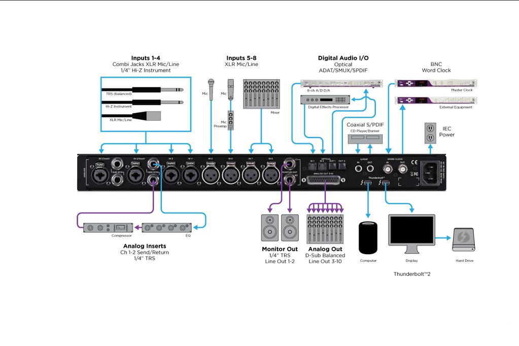
8 Rear Panel 1. Inputs 1-4: Combination (combi) jacks receive XLR or 1/4 connectors a. Use XLR for a microphone or line level input. b. Use 1/4 for high-impedance (Hi-Z) instrument. 5. Analog Out: Balanced outputs Requires a 25-pin D-Sub analog breakout cable. 6. Digital I/O: (page 30) a. Optical (Toslink): Two In/Out Ports i. ADAT, 8-channels per port, k sample rate. ii. SMUX, 4-channels per port, k sample rate. iii. S/PDIF, 2-channels per port, k sample rate. 2. Inputs 5-8: XLR for microphones or line level inputs. 3. Analog Inserts: Channels 1 & 2 (page 28) a. Send (top) - can use balanced TRS or unbalanced TS 1/4 cables. b. Return (bottom) - can use balanced TRS or unbalanced TS 1/4 cables. b. Coaxial i. Provides 2-channels of audio at sample rates of k. 7. BNC Word Clock: Used to transmit or receive word clock signal between Ensemble and other digital devices (page 37). 4. Monitor Out: Balanced TRS outputs for connecting monitor speakers. 8. Thunderbolt 2: (page 10) Two ports for daisy chaining up to six devices. It does not matter which position Ensemble is placed in the chain. Backwards compatible with Thunderbolt 1 (see Thunderbolt Notes on ). 8

9 Display Input Settings Display Screen This screen appears when an Input Select button is held for 1 second. The parameters available will change depending on the channel being viewed, and the settings made. For navigation instructions, see page Input Source a. Mic - XLR input is sent through the microphone preamp b. Inst - 1/4 input is sent through a Hi-Z to Low-Z circuit then to the microphone preamp c. +4dBu/-10dBV - Line level signal from XLR input bypasses preamp circuit. 2. Soft Limit - Attenuates transient peaks of the analog input at a threshold of -4dBfs before the signal is sent to the A/D converter (see page 53). 3. Group - 5 groups available. The gain of input channels set to the same group number are adjusted simultaneously. Any level offsets that exists before inputs are grouped will be preserved after a group is chosen. 4. Insert - Directs signal from the Input 1 or 2 Insert Return jack to the A/D converter (Insert Send is always active and can be utilized as a preamp line-out). 5. (Polarity) - Inverts the input signal s polarity 6. 48v - Toggles phantom power on/off 7. - Toggles High Pass filter (80Hz, 12dB/octave) on/off 9
10 Getting Started Precautions when powering Ensemble On/Off Before powering Ensemble On, ensure that any speakers or amplifiers connected to Ensemble s analog outputs are powered off, or the volume turned down to the minimum setting. This will prevent potential damage to your speakers and other equipment from pops that may occur as the unit boots up Power off speakers Power Ensemble On Power on speakers. Likewise, before powering Ensemble off, ensure any speakers or amplifiers connected to Ensemble s analog outputs are powered off, or the volume turned down to the minimum setting Power off speakers Power Ensemble Off Thunderbolt Notes Two Thunderbolt 2 connections on Ensemble enable daisy-chaining other Thunderbolt devices to your computer. It does not matter which position Ensemble is placed in the chain. Exception: When connecting a mix of Thunderbolt and Thunderbolt 2 devices in a chain, connect Ensemble and other Thunderbolt 2 devices to the computer first. i.e.: Thunderbolt 2 Mac > Thunderbolt 2 devices > Thunderbolt devices Up to 6 peripherals may be connected in a chain. Thunderbolt peripherals continue to operate when Ensemble is powered off. This ensures that displays, hard drives, or other essential equipment doesn t lose connection to the computer when Ensemble is not in use. A non-thunderbolt device (i.e. Firewire, HDMI, DisplayPort, etc.) may be connected to the chain, but it or the adapter for the device must be placed at the end. A Mac is compatible with Ensemble if it has the Thunderbolt logo. The Mini DisplayPort, featured on many prethunderbolt Macs, is the exact same size as the Thunderbolt port but does NOT support Thunderbolt devices. See the difference below: X Mini DisplayPort Thunderbolt Port 10


11 Ensemble Software System Requirements Computer: Thunderbolt equipped Mac Memory: 4 GB RAM minimum, 8 GB RAM recommended OS X or greater Thunderbolt Cable Download and Install Software Before Ensemble will work with the computer, special software must be installed. The latest version of the software can be downloaded from the Apogee website at: The download comes in the form of a dmg image file. Open it to view the contents. Inside you will find four items: Ensemble Thunderbolt Notes.pdf Ensemble Thunderbolt Firmware Updater.app Ensemble Thunderbolt Software Installer.pkg EnsembleThunderboltUninstaller.app Double-click to launch the Ensemble Thunderbolt Software Installer.pkg. A dialog box will appear with a series of steps to proceed. Follow the prompts to complete the installation. You will be required to restart your computer. As a result of the software install: Apogee Maestro controller software is placed in the Mac s Applications folder (see page 39). When connected, Ensemble Thunderbolt appears as an audio input/output device in Mac Sound System Preferences Ensemble Thunderbolt Firmware Updater.app is placed in the Mac s Utilities folder 11


12 Update Ensemble Firmware The first time Ensemble is used after the software installation, you will likely need to update the firmware. Warning: Do not disconnect power or interrupt the firmware update process before it is complete as this may damage the unit. 1. Make sure Ensemble is connected to the computer and is powered on. 2. Open the Ensemble Firmware Updater.app which is inside the.dmg image file downloaded from the Apogee website. There is another copy of the firmware updater app located in the Mac s Applications > Utilities folder. 3. Select Update and follow any prompts that may appear. Ensemble may reboot several times - this is normal. 4. When the progress reaches 100% and says Update Complete, you are done and can quit the updater. 12
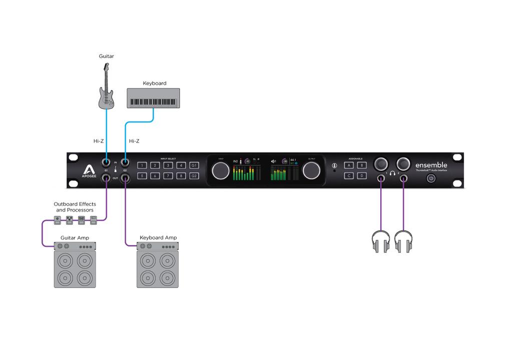
13 Connection Examples Diagram 13
14 Front Panel Controls Many Ensemble settings can be controlled from the front panel. For full control over all settings, use the Maestro software (page 39). Adjust the Input Gain 1. Turn the Input Controller knob to adjust the input gain for the selected channel. 2. Select a different channel by pressing the Input Controller knob repeatedly until the desired input is highlighted. 3. Alternatively, press one of the Input Select buttons to jump directly to that input. Accessing other Input Settings: 1. Hold an Input Select button for at least 1 second to access the Input Settings screen. 2. Turn the Input Controller knob to navigate up and down and highlight the different parameters 3. Press the Input Controller knob to change a parameter to a different setting. 4. To exit the Input Settings screen, hold the Input Select button for at least 1 second. Ensemble will automatically exit after idling for 15 seconds. For more information on the parameters of the Input Settings screen, see page 9. 14


15 Adjust Output Volume 1. Turn the Output Controller, Headphone 1, or Headphone 2 knob to adjust the respective output level. 2. Press the Output Controller, Headphone 1, or Headphone 2 knob to toggle mute on/off. Assignable Buttons Assignable buttons A, B, C, & D can be programmed to perform different functions. Press an Assignable button to perform it s programmed function. Programming of the Assignable Buttons can only be done in the Maestro application s Device Settings tab window. See page 43 and page 32 for more detailed information. The factory default settings are: A - Talkback - must hold button down B - Clear Meters C - Toggle G1/G2 output source between Thru and From Software. D - Toggle Mute function between Monitor Out and Headphones outputs. 15


16 Getting Started with Audio Software Select Ensemble for Mac System Sound Output To get sound from general audio applications such as itunes and Safari to play out of Ensemble, it must be selected as the output device in Mac System Preferences. Make sure you have already installed the most recent Ensemble Thunderbolt Software from the Apogee website before proceeding. 1. Click the apple icon in the upper-left corner of your Mac s display " 3. In the System Preferences control panel, select Sound 2. From the drop-down menu, select System Preferences At the top of the Sound Preferences panel, select the Output tab 5. Under Select a device for sound output: click Ensemble Thunderbolt Now sound from itunes or Safari will come through Ensemble s Monitor Out. For instructions on how to play itunes or Safari through a different Ensemble output, see page

![In the Audio Devices window, [Control+click] on Apogee Ensemble Thunderbolt. 3.](/docs-images/88/114783622/images/17-2.jpg "In the Menu that appears, select Configure Speakers. 4.")

17 Route Mac System Sound to Different Outputs 1. Open the Audio/MIDI Setup Utility, found in the Applications > Utilities folder of your Mac 2. In the Audio Devices window, [Control+click] on Apogee Ensemble Thunderbolt. 3. In the Menu that appears, select Configure Speakers. 4. If playing a stereo audio file, select the Stereo tab. If playing a multi-channel audio file, select the Multichannel tab. 5. Select the desired Ensemble output channel for each speaker assignment. For example, if you want itunes to play out of Ensemble channels 3 & 4, set Left Front to 3 and Right Front to Select the Apply button. 17


18 Select Ensemble in your DAW Most professional applications have their own audio preferences that are separate from the Mac System Preferences. Basic steps for setting up Ensemble are provided. For more detail on this topic, refer to the documentation that comes with your recording program. Select Ensemble in Logic Pro X 1. Go to Logic Pro X > Preferences > Audio. Select Ensemble in ProTools Go to Setup > Playback Engine. 2. In the Devices Tab, select Ensemble Thunderbolt in the Output and Input Device dropdown boxes. 2. In the Playback Engine drop-down box, select Ensemble Thunderbolt. 3. Start by setting the I/O Buffer Size to 64 Samples. This setting may need to be adjusted based on your computer s performance. 4. Select Apply Changes and close the Preferences window. 3. Start by setting the H/W Buffer Size to 64 Samples. This setting may need to be adjusted based on your computer s performance. 4. Select OK. 18


19 Select Ensemble in Ableton 1. Go to Live > Preferences. Select the Audio tab. 2. In Driver Type, select CoreAudio. 3. In Audio Input & Audio Output Device, select Ensemble Thunderbolt. 4. Start by setting the buffer size to 64 samples. This setting may need to be adjusted based on your computer s performance. 19


20 Monitoring the Input Signal Using your DAW to Monitor By default, Ensemble is configured for your recording software or DAW to perform the monitoring duty of passing your input signal on to your output. For instructions on configuring some of the major DAW programs with Ensemble, see page 18. Enable Input Monitor in Logic Pro X 1. Open Logic Pro X > Preferences > Audio Enable Input Monitor in Pro Tools In Pro Tools Native, record enable the track to activate input monitoring. 2. Make sure the box next to Software Monitoring is checked. In Pro Tools HD, the I button enables input monitoring. 3. Select the I button in each track you d like to input monitor. Enable Input Monitor in Ableton Live In the track I/O section, set the Monitor switch to Auto, or In. 20
, then you can use one of the Low-Latency Maestro Mixers built into Ensemble to monitor your signal instead. 1.")
![Open Maestro and select the Output Routing tab (or use the keyboard combination [ +5]). 2.](/docs-images/88/114783622/images/21-1.jpg "To monitor using speakers connected to Ensemble s Monitor Out 1&2: Click the left-most box next to 35")

21 Using Ensemble s Hardware Direct Monitor If you do not have any recording software open, or do not want to use it s monitoring function due to issues such as high latency (see Understanding Latency on page 51), then you can use one of the Low-Latency Maestro Mixers built into Ensemble to monitor your signal instead. 1. Open Maestro and select the Output Routing tab (or use the keyboard combination [ +5]). 2. To monitor using speakers connected to Ensemble s Monitor Out 1&2: Click the left-most box next to Mixer 1. This will cause these outputs to draw signal from the Maestro Mixer To monitor using headphones connected to HP Output 1: Click the box to the far-right of the Software Output Mixer 1 and under Hardware Output Phones 1. This will cause your Phones 1 output to draw signal from the Maestro Mixer 1. You can control the amount of input signal verses audio playback you hear using the Maestro Mixer controls: 1. Select the Mixer tab (or use the keyboard combination [ +6]). 2. Select Mixer 1 3. Adjust the level of input heard by adjusting the Input Fader [Image: Mixer Input Fader] 4. Adjust the level of audio playback from a computer program by adjusting the Software Return Fader. [Image: Software Return Fader/Channel] For a detailed description of the Maestro screens and parameters, see page
22 Guitar I/O Introduction Guitar Input Features Ensemble provides two high impedance (Hi-Z) inputs and two instrument level outputs on the front panel. The capabilities these connections provide are a powerful tool in your recording arsenal. From re-amping to setting up an instrument-level effects loop, the Ensemble s Guitar Inputs and Outputs simplify tasks that previously required specialized equipment with complex setup and configuration steps. Designed to accept a Hi-Z input signal from guitar, bass, keyboards, or other Hi-Z instruments. Dedicated circuit design different than rear panel instrument inputs. Class A JFET preamp circuit that provides the feel and responsiveness characteristic of the input circuit on a quality vintage guitar amplifier. Bootstrapping design provides an ultra-high impedance load, preserving the instrument s tone and frequency response. Assigned to software input channels 11 and 12. Guitar Output Features Impedance balanced instrument-level output designed to connect to guitar or bass amplifiers, or effects such as stomp-box pedals and processors, or similar devices. Dual mode switching Thru setting provides a zero latency direct output for the instrument connected to the guitar input. From Software setting means only non-direct signals such as audio from a DAW or the Maestro Mixer is output. Unity Gain feature takes care of level matching the input vs output signals. Assigned to software output channels 11 and 12. Re-Amping Ensemble provides a powerful way to get your best guitar tracks in a two-stage process. The first stage focuses on capturing your performance in a recording track of your DAW. The second stage routes that performance through your amps and effect pedals, allowing you to tweak settings until it s perfect so it can be recorded into your session. 22
. To keep things simple, leave Ensemble s input gain at 0dB 3. Record the performance in your DAW.")
.")
23 Stage 1: Record the Performance The dry guitar signal is recorded directly onto a track in the DAW. To do this on Ensemble: 1. Connect a guitar to a front panel guitar input on Ensemble. 2. Setup an audio track in your DAW to record from the guitar input (G1 = In 11, G2 = In 12). To keep things simple, leave Ensemble s input gain at 0dB 3. Record the performance in your DAW. Monitoring as you Record For the best performance, many players prefer to hear themselves through a guitar amp as they record. a. Connect a guitar cable from Ensemble s guitar out to an amplifier s input. b. Set the guitar output to Thru. This can be done with the front panel Assignable C button, or in Maestro s Output tab window (page 41). The guitar output when set to Thru sends a direct signal sourced from the guitar input jack. The resulting signal to your effects pedals and/or amplifier produces the same sound as if the guitar was connected directly. 23
. 2. Connect a guitar cable from Ensemble s guitar out to an amplifier s input.")
. 4. Play the DAW track to hear the performance played through the effects and amplifier.")
24 Stage 2, Part 1: Playback Through Your Guitar Rig The dry guitar recording is played out to your effects and/or amplifier. To do this on Ensemble: 1. Route the DAW s guitar track to Ensemble s guitar output (G1 = Out 11, G2 = Out 12). 2. Connect a guitar cable from Ensemble s guitar out to an amplifier s input. You can include effects pedals/ processors between Ensemble and the amplifier if desired. 3. Set the guitar output to From Software. This can be done with the front panel Assignable C button, or in Maestro s Output tab window (page 41). 4. Play the DAW track to hear the performance played through the effects and amplifier. Adjust and tweak the settings of your effects and/or amplifier until the desired sound is achieved. Stage 2, Part 2: Record the amp onto a separate DAW track The sound of the amplifier is recorded, usually with a microphone, onto another track in the DAW. 1. Place a microphone in front of the amp and connect the mic to an input on Ensemble s rear panel. 2. Make the appropriate settings to get the mic input working using Ensemble s Front Panel controls (page 14), or Maestro s Input tab window. 3. In your DAW, setup a new audio track, and set the input source to record the microphone. This process can be repeated several times. Experiment by swapping out amplifiers, changing the order and settings of effects pedals and processors, or moving the microphone in front of the amp to get different sounds. 24
25 Notes about re-amping with Ensemble: If you decide to use Ensemble s guitar input preamp to increase the dry guitar signal level into your DAW, be aware that this will also increase the track s output level to Ensemble s guitar output. If the intention is to keep the signal coming out of Ensemble at the same level as the original input, use the Unity Gain checkbox in Maestro s Output tab window to restore the output level to match the original input. Unity gain does not compensate for any changes made in the DAW. Therefore, do not alter the dry guitar track fader, or change the EQ or insert any plugins as doing so can compromise the signal to Ensemble s guitar output. Why is it important that the Output level be the same as the input level? On many guitar amplifiers, a change in the input level can significantly change the sound of the amp. Since most amps sound best with a guitar connected directly to it, Ensemble was designed to preserve the original guitar signal to achieve this result. Features such as Thru and Unity Gain are used for this purpose. As with many recording techniques, this is more of a guideline than a rule. Feel free to experiment with different levels and settings to achieve unusual sounds and unique results. Unity Gain Guitar I/O Circuit Diagram Unity Gain lowers the guitar output level by the same amount the guitar input is increased by the preamp, maintaining unity in level between the guitar input and guitar output jacks. For example, if the preamp is set to boost the input signal by +10dB, then the attenuator lowers the output by -10dB. Important: Document the preamp gain setting used when the recording is made. Since Ensemble adjusts the attenuator based on the the preamp setting, the preamp gain value may need to be recalled if re-amping at a later date. 25

26 Inserting Effects pedals Ensemble s Front Panel Guitar inputs and outputs are perfect for inserting external hardware processors designed for Hi-Z and instrument level signals - such as pedal style effects - into a track. This is not limited to guitar tracks alone, but allows you to also run vocals, drums, and other recordings through these types of effects for a unique sound. NOTE: If inserting hardware with traditional +4dBu or -10dBV line-level inputs and outputs, it s best to utilize the inputs and outputs on the rear-panel of Ensemble. 1. Route signal from your DAW to the G1 (Out 11) or G2 (Out 12) outputs. 2. Using a regular unbalanced 1/4 instrument cable, connect from the G1 or G2 Output to the Input of your first pedal. 3. Connect another 1/4 cable from the output of your last pedal to Ensemble s G1 or G2 Input. NOTE: If sending from Ensemble s G1 output, use Ensemble s G1 input to return the signal. 26
27 Main Features Analog Audio Inputs Ensemble s 12 analog audio inputs provide a multitude of connectors and options coupled with Apogee s dynamically optimized preamps and premium circuit design that provide for all the interconnections you need with your external gear. Guitar Inputs See the Guitar I/O section on page 22. Channels 1-4 Features Combi Jacks Rear Panel inputs 1-4 feature a combination (combi) input connector that is able to receive an XLR or 1/4 plug through the same jack. Set the input source via Ensemble s front panel controls (page 14), or from the Maestro software (page 40) according to the input connector being used. When using the 1/4 input, the source must be set to Inst. When using the XLR input, the source may be Mic, +4dBu, or -10dBV. When Input Source is set to: Mic - The XLR input is sent to the microphone preamp circuit. Inst - The 1/4 input is sent through a Hi-Z to Low-Z conversion circuit, then the microphone preamp circuit. +4dBu - The XLR input bypasses the microphone preamp circuit and sent to the A/D converter. -10dBV - The XLR input is converted to +4dBu, bypasses the microphone preamp, and sent to the A/D converter. 27
28 Channel 1 & 2 Analog Insert Send/Return jacks The Insert Send and Return jacks are for connecting external equipment - such as a compressors, EQ, or other signal processing gear - into the input signal chain. Engage the Insert via Ensemble s front panel controls (page 14), or from the Maestro software (page 40) according to the input connector being used Connect a 1/4 cable from Insert Send jack to the external hardware s Input jack. Connect another 1/4 cable from the output of the external gear to Ensemble s Insert Return jack. In Maestro, select the Input tab (or use keyboard combination [ +1]). Select the Insert In button to toggle the insert on/off. Special Notes: The Send/Return jacks can accommodate balanced TRS as well as unbalanced TS 1/4 connections. The Send jack is always active and can be used as a Post-Preamp direct line-out (+4dBu). The Return jack can be used as a 1/4 balanced line-in (half-normaled, +4dBu), and is only active when the In button is selected. Channels 5-8 Features Rear-panel inputs 5-8 feature an XLR jack for connecting microphones or line-level signals. Set the input source via Ensemble s front panel controls (page 14), or from the Maestro software (page 40) according to the input connector being used. When Input Source is set to: Mic - The XLR input signal is sent to the microphone preamp circuit. +4dBu - The XLR input signal bypasses the microphone preamp circuit and sent to the A/D converter. -10dBV - The XLR input signal is converted to +4dBu, bypasses the microphone preamp, and sent to the A/ D converter. Analog Input Circuit Diagram 28
29 Built In Mic Ensemble features a built-in mic on the front panel that can be recorded, or used for the Talkback function (page 31). Recording the Built-In Mic Ensemble s Built-In Mic can be recorded into your computer in the same way as the other inputs on the Ensemble. This provides a convenient room mic for enhancing your recordings, or even as a convenience to make a quick recording instead of having to setup an external mic first. Because Ensemble requires inputs to be assigned as pairs, the Built-In Mic is assigned to channels 9/10. Even though the mic assigned to two channels, it is not stereo. Instead the mono signal is duplicated to both channels. In your DAW, set the track s Input Source to Channel 9 or Channel 10. The Built-In Mic gain is controlled from the Input window in Maestro (page 40). Analog Audio Outputs Ensemble provides 12 analog outputs for connecting to your external gear. Monitor Out L1 & R2 Ensemble s Monitor Out L1 & R2 are designed to connect to studio monitor speakers. These outputs are controlled by the Output Controller knob, but can be set to a fixed line-level output via the Maestro software. See the Monitor Control Center section on page 31 for more information on configuring these outputs. Balanced 1/4 TRS outputs Can be configured as a fixed line-out Can be set to +4dBu or -10dBV via Maestro (page 41) Listed as Out 1/2 in Maestro and DAW software Analog Out 3-10 Ensemble provides additional balanced analog outputs via a 25-pin d-sub connector. Connect a analog out breakout cable to this connector to access these outputs. These outputs are set as fixed line-level outputs by default, but outputs 3-6 can be adjusted by the Output Controller knob when multiple speaker sets (page 33) or 5.1 surround monitoring (page 34) is enabled. See the Monitor Control Center section on page 31 for more information on configuring these outputs. Balanced 25-pin D-Sub Output Can be set to +4dBu or -10dBV via Maestro (page 41) 29
30 Guitar Outputs See the Guitar I/O section on page 22. Digital I/O Ensemble provides multiple ports of digital inputs and outputs, providing up to 18 channels of digital I/O for connectivity to your digital gear. Optical Two pairs of optical (Toslink) in and out ports are provided. These ports can be configured independently via the Maestro software (page 47) to use ADAT/SMUX or S/ PDIF protocols, and are capable of sample rates between k. ADAT k Sample Rates - 8 channels of audio provided per port - 16 channels total when using both ports SMUX k Sample Rates - 4 channels of audio provided per port - 8 channels total when using both ports S/PDIF k Sample Rates - 2 channels of audio provided per port - 4 channels total when using both ports Coaxial A coaxial digital in and out port are provided and are capable of sample rates between k. S/PDIF k Sample Rates - 2 channels of audio provided 30
. It can also be activated in Maestro by clicking the button in the Toolbar (pg 39).")
31 Monitor Control Center Ensemble is equipped with several monitoring features to provide for your monitoring needs. Talkback The Talkback feature is activated by holding down an Assignable button (A is default). It can also be activated in Maestro by clicking the button in the Toolbar (pg 39). Using the Built-In Mic for Talkback The Built-In Mic is used for talkback by default. In case this has been changed, here s how to make the appropriate settings to return this function: 1. Open Maestro and select the Device Settings tab at the top (or use the keyboard combination [ +3]). 2. Under Talkback Mic Source, select Built-In Mic from the drop-down box. 3. To adjust the Built-In Mic s Gain setting, click the Input Tab at the top (or use the keyboard shortcut [ +1]). 4. Drag the knob in the Built-In Mic channel up or down to the desired setting. Using an External Talkback Mic An external microphone can be used for the Talkback function. Here s how to configure this option: 1. Connect the microphone to XLR Input 8 on Ensemble s rear panel. 2. Open Maestro and click the Device Settings tab (or use the keyboard combination [ +3]). 3. Under the Talkback section, change the dropdown box from Front Panel to Mic In Select the Input tab (or use the keyboard combination [ +1]). 5. On Input 8, activate phantom power if necessary, and adjust the Gain and other settings to adjust the external Talkback Mic s level. (page 40) Note: Mic settings for input 8 can also be made from Ensemble s front panel. 31
![Choosing the Talkback Mic Destination 1. Open Maestro and select the Device Settings tab at the top (or use the keyboard combination [ +3]). 2.](/docs-images/88/114783622/images/32-0.jpg "Sound from the Talkback Mic can be sent to one or more of the following destinations: Headphone 1 Headphone 2 Analog Output 9-10 Setting an Assignable Button to activate Talkback From the")
. 2.")
32 Choosing the Talkback Mic Destination 1. Open Maestro and select the Device Settings tab at the top (or use the keyboard combination [ +3]). 2. Sound from the Talkback Mic can be sent to one or more of the following destinations: Headphone 1 Headphone 2 Analog Output 9-10 Setting an Assignable Button to activate Talkback From the factory, Assignable A is programmed to activate Talkback. However, any of the Assignable buttons can be set for this function: 1. Open Maestro and and click the Device Settings tab (or use the keyboard combination [ +3]). 2. Under the Assignable Buttons section, click the Button A, B, C, or D drop-down box and select Engage Talkback. 3. The Talkback function is on while the Assignable button is held down (momentary). 32

![Open Maestro and click the Output tab (or use the keyboard combination [ +2]). 2. In the Speaker Output section click the Speaker Output drop-down box and select Line.](/docs-images/88/114783622/images/33-1.jpg "Note: This disable s Ensemble s Monitor Output level control. How to Setup and Use Multiple Speaker Sets It is possible to connect up to three pairs of speaker monitors and toggle between them.")

33 How to set the Monitor Outputs as a fixed Line-Out This setting changes the Monitor Outputs from a variable volume controlled by the Output Controller knob to a fixed output at the full +4dBu or -10dBV reference level. This setting is convenient for connecting Ensemble to an external monitor control device such as a mixer or control center. 1. Open Maestro and click the Output tab (or use the keyboard combination [ +2]). 2. In the Speaker Output section click the Speaker Output drop-down box and select Line. Note: This disable s Ensemble s Monitor Output level control. How to Setup and Use Multiple Speaker Sets It is possible to connect up to three pairs of speaker monitors and toggle between them. This is very useful to check how a mix sounds through different speakers and systems. 1. Connect the first pair of speakers to Monitor Out 1/2, the second pair to Line Out 3/4, and if desired a third pair to Line Out 5/6. 2. Open Maestro and click the Output tab (or use the keyboard combination [ +2]). 3. From the Speaker Output Select drop-down box, select 2 Speaker Sets or 3 Speaker Sets. 4. Click the Speaker Set 1, 2, or 3 button to select which speaker set is active. Note: To activate multiple speaker sets simultaneously, hold down [command ] and select another speaker set button. 33
. 2. Click on the desired Assignable Button dropdown box and choose a speaker set to engage.")


34 Using the Assignable Buttons to Change Speaker Sets The Assignable buttons can be programmed to change speaker sets. 1. Open Maestro and click the Device Settings tab (or use the keyboard combination [ +3]). 2. Click on the desired Assignable Button dropdown box and choose a speaker set to engage. Note: Simultaneous Speaker Sets cannot be engaged by the front panel Assignable Buttons. How to connect and configure a Surround Speaker Setup When using Ensemble with a surround speaker setup, the first six outputs can be configured as speaker outputs suitable for connection to a 5.1 speaker system. With this configuration, turning the Output Controller knob will adjust all six line-outputs simultaneously. 1. Connect your speakers to Ensemble s outputs 1-6. A standard 5.1 surround setup is routed as follows: Output 1: Front Left Output 2: Front Right Output 3: Center Output 4: Sub-woofer Output 5: Left Surround Output 6: Right Surround 2. Open Maestro and click the Output tab (or use the keyboard combination [ +2]). 3. In the Speaker Output section, click the Speaker Output drop-down box and select
35 Adjust for Volume Differences Between Speakers There may be cases where the perceived volume of one of two or three speaker sets, or a speaker in a surround setup, is slightly different from the others. The output Trim controls in Maestro can be used to compensate for this so all speakers produce the same perceived volume levels. 1. Open Maestro and select the Output tab window. 2. Select the Show Trims button. Trims only allow a reduction in signal level. Lower the trim of a speaker or speaker set that is too loud. If a speaker or speaker set is too quiet, then leave the trims of those speakers at maximum, and lower the trim of all the other speakers to match. 35
36 Setup Multiple Headphone/Speaker Mixes via Maestro Mixer Since there are four low-latency mixers in Maestro, these can send different mixes to the various Ensemble audio outputs. For example, send one mix to the Headphone 1 output and a different mix to the Headphone 2 output, as well as different mixes to the rear-panel Monitor Outputs and Analog Outputs. 1. Open Maestro and click the Output Routing tab (or use the keyboard combination [ +5]). 2. Route a Hardware Output listed at the top of the grid to one of the four Mixer Software Outputs available on the left of the grid by clicking the box where they intersect. This places an x in that location. 3. If desired, continue routing other Hardware Outputs to any of the other three Mixer Software Outputs. 4. Select the Mixer tab (or use the keyboard combination [ +6]). 5. On the Left, show or hide the four mixers by selecting the mixer 1, 2, 3, or 4 button. 6. Adjust the mixer channel faders, pan controls, and other settings to achieve the sound desired. 36

![Open Maestro and select the System Setup tab (or use the keyboard combination +7]). 2. In the Clocking Section, set Clock Source to Internal. 3.](/docs-images/88/114783622/images/37-2.jpg "When Ensemble is using it s internal clock, the front panel output display will show INT. Clock signal is sent to all of Ensemble s digital audio outputs and BNC Word Clock output. 4.")
37 Clocking with External Equipment When connecting digital audio cables between Ensemble and another digital audio device, a clocking relationship must also be set. Whether connecting two or more devices, one must be set as the clock master, and all other devices must be set as clock slaves. Configure Ensemble as Clock Master 1. Open Maestro and select the System Setup tab (or use the keyboard combination +7]). 2. In the Clocking Section, set Clock Source to Internal. 3. When Ensemble is using it s internal clock, the front panel output display will show INT. Clock signal is sent to all of Ensemble s digital audio outputs and BNC Word Clock output. 4. Connect a digital audio cable (optical or coaxial) out of Ensemble and into the external equipment. Or connect a BNC Word Clock cable from the OUT of Ensemble to the IN of the external equipment. NOTE: When connecting via BNC cable, make sure you follow appropriate termination practices (page 49). 5. Make the appropriate settings on the external equipment to set it as a slave. The sample rate must match on both devices. Though the Slave device may automatically switch to the appropriate sample rate, this may not always occur and the sample rate will need to be set manually. 37
38 Configure Ensemble as Clock Slave 1. Set the external device as the clock master. 2. Connect a digital audio cable (optical or coaxial) out of the external device and into Ensemble. Or connect a BNC Word Clock* cable out of the external gear to Ensemble s BNC IN port. 3. Open Maestro and select the System Setup tab (or use the keyboard combination +7]). 4. In the Clocking Section, set Clock Source to the appropriate external connection. Set the Clock Source to ADAT, SMUX, or SPDIF Optical when using an optical cable. Ensemble s front panel will also reflect the source. Set the Clock Source to SPDIF Coax when using a coaxial audio cable. Ensemble s front panel will also reflect the source. Set the Clock Source to Word Clock when using a BNC word clock cable. Ensemble s front panel will also reflect the source. * BNC is the preferred method of transferring digital clock. Use this connection whenever possible and make sure to follow appropriate termination practices (page 49). If Ensemble doesn t receive or is unable to lock to a external clock source, the display s clock source indication will turn red, and the sample rate will blink. When this happens, check your connections for a bad or misconfigured cable, and make sure the sample rate of the master and slave devices are set to the same value. Termination Termination only needs to be considered when using Ensemble s BNC word clock connections. See page 49 to determine if termination should be disabled for your particular setup. 38
39 Maestro Apogee Maestro is a controller software for your Ensemble Thunderbolt. Though you do not need Maestro open to use your Ensemble Thunderbolt, it provides access to all of Ensemble s settings and parameters. It s level meters are also a useful diagnostic tool to see which inputs and outputs are receiving and sending signal. Maestro Features While only basic settings may be made from the front panel controls, all Ensemble features are available and can be controlled from Apogee Maestro software. Devices Sidebar Any Maestro-compatible Apogee interface connected to the host computer are displayed in the Devices sidebar. Hardware settings are displayed by first selecting one or more interfaces in the Devices sidebar and then clicking on a tab. Device Icon and ID Button A device icon and ID button is placed adjacent to each row of parameters to identify the hardware unit to which the row belongs. By clicking on the ID button, the corresponding hardware unitʼs front panel will illuminate. Each hardware unit is assigned a Peripheral Prefix (A-Z, found in Maestroʼs Device Settings tab window page 43) which is displayed on the ID button. Toolbar Clear Meters - This button clears all held peak and over indications on all hardware and software meters. 2. System Status - This window displays the sample rate, clock source, and system status of the currently selected system. A system status of Ready indicates that all detected units are properly connected and clocked. 3. Talkback Mic - This button activates the talkback microphone. It must be held down to remain active. 4. Toolbar Monitor Controls - These controls offer immediate access to one peripheral s speaker and headphone volume controls, regardless of the Devices Sidebar selection. 39

40 Input Tab Window Settings for Ensemble s analog and digital inputs are found in the input tab Analog Level - Use this drop down menu to choose the analog level for each A/D conversion channel. Option+click any channel to set the reference for all channels Choose Mic when connecting microphones or direct boxes, or any devices that needs to run through a microphone preamplifier. -XLR Input only Choose Inst when connecting a guitar or keyboard, or any high impedance (Hi-Z) instrument to the 1/4 input (balanced TRS or unbalance TS). The signal is sent through a Hi-Z to Low-Z conversion circuit before sent through the microphone preamplifier circuit. Choose +4dBu when connecting to pro gear, such as en external mic pre, compressor, or EQ, with outputs at a +4dBu nominal level. Choose -10dBV when connecting to semi-pro, hi-fi, or musical instrument gear with outputs at a -10 dbv nominal level. 2. Soft Limit - Select On to engage. This option begins to attenuate transient peaks at a threshold of -4dBfs. 3. Gain Control - Use to adjust the gain of the microphone preamp. Not available when the input is set to +4dBu or -10dBV. 4. Group - The gain of input channels set to the same group number are adjusted simultaneously. Any level offsets that exists before inputs are grouped will be preserved after a group is chosen. 5. Insert In (ch 1/2 only) - When this button is engaged, the signal to the Insert Return jack is routed to the A/D converter. Note that the Insert Send is always active and thus may be used as an analog direct out. 6. Polarity - Use this button to invert the polarity of the input signal Use this button to enable 48 volt phantom power on the corresponding Analog In channel. Condenser mics require 48 volt phantom power to operate. 8. High Pass - Use this button to engage an 80Hz, 12db/octave high-pass filter on the input. 40
41 Output Tab Window Settings and controls for Ensemble s analog and digital outputs are found in the Output tab Analog Level - Use this drop down menu to choose the analog level for each D/A conversion channel. Option+Select any channel to set the reference for all channels. Choose +4dBu when connecting to pro gear with inputs at a +4dBu nominal level. Choose -10dBV when connecting to semi-pro, hi-fi, or musical instrument gear with inputs at a -10 dbv nominal level. 2. Show/Hide Trims - Displays or hides the Trim faders 3. Reset Trims - Resets all Trim faders. 4. D/A Meter - Displays the level of the output before D/A conversion. The following settings control the behavior of the Guitar 1 and Guitar 2 outputs: 5. Output Source - Determines the signal sent to the Guitar Out. Thru: The signal from the guitar input is passed directly to the guitar output. Guitar input signal continues to also pass to the computer s software inputs. From Software: Only audio coming from the computer is heard. This setting is useful for playing back audio from a DAW to an instrument amplifier. 6. Unity Gain: - Attenuates the Guitar Out level to counter the gain boost of the Guitar In preamp. This setting causes the output signal strength to equal the input signal strength and is useful when software monitoring through a DAW. (i.e.: If the Guitar Input preamp gain is set to increase the guitar input signal by +20dB, the guitar output signal is decreased by -20dB.) 41
42 The following settings control the configuration and level of the rear panel analog outputs and front panel headphone outputs. 1. Speaker Level -Controls the speaker output level. 2. Analog Out Format -Sets the format of the analog outputs. Line: Monitor Out 1/2 are configured as line outputs. Functions such as level control, Mute, Dim, and Sum to Mono are disabled. 1 Stereo: Monitor Out 1/2 are configured as speaker outputs (with all monitor functions available). Outputs 3-10 are configured as line outputs. 2 2 Speaker Sets: Monitor Out 1/2 and outputs 3/4 are configured as two pairs of stereo outputs. Switch between the stereo pairs with the Speaker Select buttons. These outputs are adjusted simultaneously with the Output Controller knob. 3 Speaker Sets: Monitor Out 1/2 and outputs 3-6 are configured as three pairs of stereo outputs. Switch between the stereo pairs with the Speaker Select buttons. These outputs are adjusted simultaneously with the Output Controller knob. 5.1: Monitor Outputs 1/2 and Analog outputs 3-6 are configured as speaker outputs, suitable for connection to a 5.1 speaker system. These outputs are adjusted simultaneously with the Output Controller knob Headphone Level -Controls the output level of the corresponding headphone output. 4. Mute -Select M to mute the speaker or headphone output. 5. Dim -Select D to lower the speaker or headphone output level by 15dB. This function is a convenient for briefly lowering the playback volume in the speakers or headphones in order to hold a conversation without completely muting the output. 6. Sum to Mono -Select to combine the left and right channels of the speaker or headphone outputs to mono. This function is useful to check mono compatibility of a stereo signal. Show Trims This button reveals output attenuation controls. Use these trims to compensate for variations in the perceived output level of individual speakers or speaker sets connected to Ensemble s analog outputs. 42
43 Device Settings Tab Window Peripheral Prefix -Choose which Peripheral Prefix (A-Z) is displayed on the ID button. 2. Assignable Buttons -Use these menus to select the parameter controlled by the front panel assignable buttons. Mute: This assigns one of the front panel buttons to mute the speaker and/or headphone outputs. Dim: Assign to headphones or speakers to lower the output volume by -15dB. This function is convenient for briefly lowering the playback volume in the speakers or headphones without completely muting the output. Sum to Mono: This function is used to examine phase relationships on stereo tracks. When engaged, the left and right outpu signals are combined and phase errors between the two become more noticeable. Engage Speaker Set: Choose this option to engage a particular speaker set when a front panel Assignable Button is pressed. Note this only works when the Output format (found in Maestro s Output Tab) is set to either 2 Speaker Sets or 3 Speaker Sets. Toggle Guitar Out Thru - From Software: When selected, the Assignable button will change the Guitar Output source between THRU operation and FROM SOFTWARE operation. Clear Meters: Removes any peak and over indicators in Maestro and on Ensemble s front panel display. Engage Talkback: When selected, the assignable button must be held down to engage talkback. 3. Talkback Mic Source 4. Talkback Mic Destination -Use this menu to select the talkback microphone source. The input source s gain control and other features are adjusted from the Input tab window. -Select the checkbox to route audio from the talkback microphone to Ensemble s Headphone 1, Headphone 2, or Line 9-10 outputs. 5. Optical Format -This determines which audio format is transmitted and received through the optical In and Out ports. SPDIF: The two-channel SPDIF audio format is transmitted and received through the selected port s In and Out connections. This format is capable of utilizing a maximum sample rate of 96kHz. ADAT/SMUX: The multi-channel ADAT or SMUX format is transmitted and received through the selected port s. The ADAT protocol is used for sample rates of 44.1kHz - 48kHz allowing up to 16 channels of digital I/O through both Port 1 and Port 2. The SMUX protocol is used for sample rates of 88.2kHz - 96kHz allowing up to 8 channels of digital I/ O through both Port 1 and Port WC Input Termination -Except for specific situations outlined on page 49, leave this box checked at all times. 43

44 Input Routing Tab Window The number of input channels that are available to a computer recording program is determined by Ensemble s Core Audio driver. The Input Routing window determines how Ensemble s physical hardware inputs are routed to these software inputs Hardware Inputs Columns 2. Software Inputs Rows 3. Software Inputs Labels -The hardware analog and digital inputs of all peripherals connected to Ensemble are displayed in these columns. -Available audio software inputs are displayed in these rows in pairs (1-2, 3-4, etc.) -Once a connection has been made between hardware and software inputs, the software input label (consisting of the peripheral prefix plus the hardware input label) appears in these fields. For these labels to appear in your Audio software input/output assignments, ensure that the software is set to accept labels transmitted through Ensemble s Core Audio driver. 4. Reset Routing - Restores the factory default routing. Audio connections between hardware and software inputs are made by positioning markers on the routing grid at the intersection of the desired hardware and software channels. By default, hardware inputs are routed sequentially to software inputs. Note that the movement of markers is restricted based on the routing capability of the system. On the Input Routing page, one hardware input may be assigned to multiple software inputs (in effect splitting the signal) but multiple hardware inputs may not be assigned to one software input (an operation which would require the summing of input signals). Each markers range of motion is indicated by the horizontal shading on the routing grid, as depicted above by arrows on the input routing grid. 44

45 Output Routing Tab Window The number of output channels that appear to audio programs in the computer is determined by Ensemble s Core Audio driver. The Output Routing tab window determines how these software outputs are routed to Ensemble s physical hardware outputs Hardware - The hardware analog and digital outputs of all peripherals connected to Ensemble are Outputs Columns displayed in these columns. 2. Software Outputs Rows -Available audio software outputs are listed in these rows in pairs (1-2, 3-4, etc.) 3. Mixer 1-4 Outputs -The four low latency mixer outputs appear at the bottom of the Software Outputs list, Rows and may be assigned to one or more hardware output pairs. 4. Software Outputs Labels -Once a connection has been made between software and hardware outputs, the software output label (consisting of the peripheral prefix plus the hardware output label) appears in these fields. 5. Reset Routing - Restores the factory default routing. Manipulation of the Output Routing Tab Window is essentially the same as the Input Routing Tab Window, with the important distinction that one software output may be assigned to multiple hardware outputs but multiple software outputs may not be assigned to one hardware output. Each marker s range of motion is indicated by the vertical shading on the routing grid, as depicted above by arrows on the Output routing grid. Note that each marker represents an odd-even pair of audio signals - it s not possible to route the odd and even signal of a pair to different destinations. 45

46 Mixer Tab Window The Maestro Mixer provides a low latency patch from Ensemble s inputs to its outputs. This is useful for when latency through software audio applications are too long, but also when wanting to monitor your input signal without needing to have an audio software application open at all Four independent mixers are provided for various uses, such as where multiple performers each require a different low latency mix. 1. Mixer 1-4 -Use these buttons to show or hide any of the four mixers from view. 2. Pan -This rotary knob pans the input signal between the left and right sides of the mixer s stereo output. 3. Input Fader and Readout -This slider sets the level of the input signal tin the mixer s stereo output. The level of the fader is indicated in the adjacent window. 4. Input Meter -This bar-graph meter displays the pre-fader input level. 5. Input Solo -This button mutes all input channels whose Solo buttons are not engaged. 6. Input Mute. -This button mutes the input channel 7. Input Custom -Alphanumeric labels may be entered in these text boxes. Label 46


47 Mixer Tab Window (Continued) Software Return -This stereo input channel draws signal from your software audio application. Use the drop down menu to select which stereo pair from software is heard through the mixer. 9. Mixer Master -This section of the mixer provides level control and metering for the mixer s output. System Setup Tab Window In most cases, Ensemble hardware interface is part of a larger Mac-based audio system. Settings that encompass the integrated hardware-software system are found on this tab window. 1. Clock Source -This drop down selects the clock source for Ensemble. The following sources may be selected: Internal: Ensemble is clocked from its internal crystal. Word Clock: Ensemble is clocked from an external word clock signal connected to the rear panel BNC input. SPDIF Coax, SPDIF Optical, ADAT, or SMUX: Ensemble is clocked from a digital audio input. The clock sources listed will vary depending on sample rate and optical input settings. 2. Sample Rate -Selects Ensemble s sample rate. In some cases this setting may be overridden by software running on the computer (i.e. When a DAW session project is open). 3. Peak Hold -Sets the time that peak indications are held on software and front panel meters. 4. Over Hold -Sets the time that over indications are held on software and front panel meters. 5. Keyboard -The audio system may be configured so that the Mac keyboard volume controls set the Volume Control output level of Ensemble s speaker or headphone outputs. 47


48 Menu Bar Menus About Apogee Maestro - Choose this menu item to display version information for all the hardware connected and software elements installed on your Mac. Preferences - Choose this menu item to display Maestro s Preference panel. Launch Maestro automatically when connecting a device - This launches Maestro when an Apogee device is connected to the computer. Display pop-ups - check this box to cause a transparent overlay to appear on your mac screen whenever the speaker or headphone levels are adjusted. Hide Apogee Maestro - Choose this menu item to hide the Maestro application. Hide Others - Choose this menu item to hide all other open applications. Show all - If any open applications have been hidden, choose this menu item to reveal all open applications. Quit Apogee Maestro - Choose this menu item to quit Maestro. Rescan - Choose this menu item to re-initialize the link between Maestro and Apogee hardware connected to the Mac, in the case where the hardware is correctly connected and powered on but not detected by Maestro. Selecting an item in the Window Menu switches to a view of that selection. 48
 Input Termination checkbox located in the Maestro software s Device Settings window (pg 43).")

49 Reference BNC Termination Best Practices Ensemble provides an internal termination mechanism for the BNC input. This mechanism is manipulated by the Word Clock (WC) Input Termination checkbox located in the Maestro software s Device Settings window (pg 43). In general, leave Ensemble s WC Input Termination checked at all times. This applies even when Ensemble is being used as the master clock for other devices. The only time this box should be unchecked is when Ensemble is slaving to external clock AND passing the signal through the BNC Out to another device. Word Clock Input Termination box CHECKED: Ensemble is Master, sending it s internal WC to external devices Ensemble is WC Slave to external clock and is the last device in the chain Word Clock Input Termination box UNCHECKED: Ensemble is slaving to external clock AND passing WC on to another device. 49


50 Why is Word Clock Termination Important? Word Clock is used to determine the timing of when an audio sample is taken. On a standard CD, there are 44,100 audio samples in each second so it s vital that each sample be taken at the appropriate time or the audio will become warped and inaccurate resulting in poor audio clarity. When the Word Clock signal travels over a BNC coaxial cable and arrives at the receiving device, the signal reacts in certain ways: If the receiving device is not terminated, the Word Clock signal reacts like a wave of water hitting a hard wall. The signal bounces off the wall and creates a backwash or reflection that perturbs the incoming signal with extra peaks and troughs and can result in increased jitter and other clock errors. When proper termination is attained, instead of hitting a hard wall, it s like the Word Clock signal hits a pliable gate that absorbs some of the signal and prevents any backwash or reflection from happening, keeping things clean and accurate. For more in-depth information on this topic, see the Big Ben Termination: How and Why pdf document located on the Apogee website at bigben_termination.pdf 50
51 Understanding Latency What is latency? When recording with most computer-based digital audio applications, a delay between the input and output of the recording system often disturbs the timing of the musicians who are performing. This delay, known at latency, means that the musician hears the notes he produces a few milliseconds after having produced them. As anyone who has spoken on a phone call with echo knows, relatively short delays can confuse the timing of any conversation, spoken or musical. To illustrate the effect of latency, Figure A depicts the typical signal path of a vocal overdub session. A vocalist sings into a microphone, which is routed through a hardware interface to the audio software application for recording. In the software application, the vocalist s live signal is mixed with the playback of previously recorded tracks, and routed back through the hardware interface to the vocalist s headphones. Because of the audio application s latency, the vocalist hears his performance delayed by several milliseconds in his headphones. 51
52 How does Maestro resolve latency? By routing the hardware input directly to the hardware output and mixing in playback as shown in Figure B, it s possible to create a headphone listening signal with a much shorter delay. First, the signal being recorded (in this case, a vocal mic) is split in the hardware interface and routed to both the software application for recording and directly back to the hardware outputs without going through the latencyinducing software; this creates a low latency path from mic to headphones. Next, a stereo mix of playback tracks is routed to the low latency mixer and combined with the hardware input(s). This allows the performer to hear both himself without a confusing delay plus the playback needed for overdubbing. Note that the software application s mixer is used to set a stereo mix of playback tracks while the low latency mixer is used to set the balance between the stereo playback mix and the hardware inputs. Do I need the Maestro Mixer? The Maestro mixer serves to provide a low latency listening mix while recording. Therefore if you re using Ensemble to listen to itunes or audio from another program, there s no need to use the mixer. It s also possible that the latency of your particular recording system is low enough to be unnoticeable by you or other performers, especially since Ensemble uses the very efficient Thunderbolt 2 Technology. If you ve set your audio software s input/output buffers according to the guidelines below and latency doesn t bother you or other performers, there s no need to use the Maestro mixer. 52
53 How do I set my software s I/O Buffer? The I/O Buffer setting found in most audio software is one of the most crucial, but often ignored, settings in a Mac-based recording system. When choosing a buffer setting, a compromise between the latency through the application and the amount of computer processor power accessible to the application must be made. A lower Buffer setting results in lower latency but less available processing power. If the application can t access enough processor power, processor overruns may occur, resulting in audible clicks and pops or error messages that interrupt playback and recording. A higher Buffer setting, on the other hand, results in greater amount of accessible processor power (i.e. less chance of overruns) but increases the latency. Determining the best setting requires some trial-and-error in order to find the best compromise. Keep in mind that as tracks and plug-ins are added to a software session, processor requirements increase. Thus, the buffer setting that works during the early stages of a session might result in processor overruns during later stages. The best strategy is to set the buffer to a lower setting during recording and accept certain limitations on plug-in usage, and then raise the buffer during mixing to utilize the computer s full processor power when latency isn t an issue. With the processing power of today s Macs, you may find that adjustment of the Buffer isn t necessary, and you can leave it at a setting for low latency and still access a sufficient amount of processing power when adding tracks and plug-ins. If you do encounter clicks, pops or software errors, don t hesitate to experiment with the Buffer setting. Soft Limit Soft Limit is Apogeeʼs proprietary analog process for taming transients before A/D conversion. By gently rounding transients in a transparent manner, itʼs possible to maximize level BEFORE the A/D conversion stage and prevent unwanted distortion from clipping. When to use Soft Limit Soft Limit is an analog process that instantaneously rounds transient peaks beginning at -4dbfs. For all intents and purposes attack and release times may be considered instantaneous. As with any peak reduction device working at such fast time constants, Soft Limit is most effective with signals whose peak information is much greater than its average (or RMS) information, such as drums, percussion and plucked instruments. Soft Limit may not be the appropriate choice for limiting signals whose crest factor (peak to RMS ratio) is low, such as bass or organ. 53

54 Specifications System Requirements Computer: Intel Thunderbolt Equipped Mac Memory: 4GB RAM minimum, 8GB recommended OS X or later Thunderbolt cable Pinout Diagram for Analog Output 3-10 *Thunderbolt and the Thunderbolt logo are trademarks of Intel Corporation in the U.S. and/or other countries. The Mini DisplayPort, featured on many pre-thunderbolt Macs, is the exact same size as the Thunderbolt port but does NOT support Thunderbolt devices. X Mini DisplayPort Thunderbolt Port Factory Hardware Reset / Initialize To return Ensemble to the factory default settings: 1. Start with Ensemble turned off. 2. Hold down the Output Controller knob. 3. Turn Ensemble on. 4. When the Apogee Splash screen clears and the Display shows the Level Meter screens, let go of the Output Controller knob. This completes the hardware reset of Ensemble. 54
$2495. Ensemble 30x34 Thunderbolt Audio Interface HIGHLIGHTS. For more information, visit apogeedigital.com/products/ensemble
 Ensemble 30x34 Thunderbolt Audio Interface $2495 The new Apogee Ensemble is the first Thunderbolt 2 audio interface to offer superior sound quality, the lowest latency performance and the most comprehensive
ProFire 610. English. User Guide
 English User Guide User Guide Introduction............................................................ 3 What s in the Box........................................................ 3 Your ProFire 610 package
USB AUDIO INTERFACE I T
 USB AUDIO INTERFACE EN DE FR ES IT JA Contents Introduction...3 Contents in this Operation Manual... 3 Features... 3 Panel Controls and Terminals (Details)...4 Rear Panel... 4 Front Panel... 6 Panel Controls
Reference Guide 2014 ZOOM CORPORATION. Copying or reprinting this manual in part or in whole without permission is prohibited.
 Reference Guide 2014 ZOOM CORPORATION Copying or reprinting this manual in part or in whole without permission is prohibited. Introduction is a mixer application designed specifically for the. Using a
3124mb+ All Discrete 4 Channel Mic/Instrument Preamplifier with Stereo Mixer Operator s Manual
 3124mb+ All Discrete 4 Channel Mic/Instrument Preamplifier with Stereo Mixer Operator s Manual Written by Carl J Houde 2015 Table of Contents 1.0 Introduction... 3 2.0 Overview... 4 2.1 3124mb+ Features
LavryBlack Series Model AD11 Stereo Analog to Digital Converter With Microphone Preamplifier
 LavryBlack Series Model AD11 Stereo Analog to Digital Converter With Microphone Preamplifier Lavry Engineering, Inc. P.O. Box 4602 Rolling Bay, WA 98061 http://lavryengineering.com email: techsupport@lavryengineering.com
10 in 10 out PCI Digital Recording System with S/PDIF. User Guide
 10 in 10 out PCI Digital Recording System with S/PDIF User Guide Table of Contents Introduction.............................. 3 What s in the Box?.......................... 3 About the Delta 1010 Digital
Element 78 MPE-200. by Summit Audio. Guide To Operations. for software version 1.23
 Element 78 MPE-200 by Summit Audio Guide To Operations for software version 1.23 TABLE OF CONTENTS IMPORTANT SAFETY AND GROUNDING INSTRUCTIONS COVER 1. UNPACKING AND CONNECTING...3 AUDIO CONNECTIONS...4
ULN-8 Quick Start Guide
 Metric Halo $Revision: 1671 $ Publication date $Date: 2012-7-21 12:42:12-0400 (Mon, 21 Jul 2012) $ Copyright 2012 Metric Halo Table of Contents 1.... 5 Prepare the unit for use... 5 Connect the ULN-8 to
LIO-8 Quick Start Guide
 Metric Halo $Revision: 1051 $ Publication date $Date: 2011-08-08 12:42:12-0400 (Mon, 08 Jun 2011) $ Copyright 2010 Metric Halo Table of Contents 1.... 5 Prepare the unit for use... 5 Connect the LIO-8
SIGNAL PROCESSOR. Operation Manual
 SIGNAL PROCESSOR Operation Manual Using the PDF manual From the Contents on page 2, click on the desired topic to automatically jump to the corresponding page. Click on a link in this manual to jump to
SIGNAL PROCESSOR. Operation Manual
 SIGNAL PROCESSOR Operation Manual Using the PDF manual From the Contents on page 2, click on the desired topic to automatically jump to the corresponding page. Click on a link in this manual to jump to
M-16DX 16-Channel Digital Mixer
 M-6DX 6-Channel Digital Mixer Workshop Getting Started with the M-6DX 007 Roland Corporation U.S. All rights reserved. No part of this publication may be reproduced in any form without the written permission
Mastering Analog to Digital / Digital to Analog Converter. User Manual Including February 2017 Version 8 Firmware and Feature Update
 Mastering Analog to Digital / Digital to Analog Converter User Manual Including February 2017 Version 8 Firmware and Feature Update Lynx Studio Technology, Inc. www.lynxstudio.com support@lynxstudio.com
CFX 12 (12X4X1) 8 mic/line channels, 2 stereo line channels. CFX 16 (16X4X1) 12 mic/line channels, 2 stereo line channels
 8 mic/line channels, 2 stereo line channels. CFX 16 (16X4X1) 12 mic/line channels, 2 stereo line channels") COMPACT CFX MIXERS COMPACT SOUND REINFORCEMENT MIXERS WITH EFX FOR THE GIGGING MUSICIAN THREE MODELS CFX 12 (12X4X1) 8 mic/line channels, 2 stereo line channels CFX 16 (16X4X1) 12 mic/line channels, 2
COMPACT CFX MIXERS COMPACT SOUND REINFORCEMENT MIXERS WITH EFX FOR THE GIGGING MUSICIAN THREE MODELS CFX 12 (12X4X1) 8 mic/line channels, 2 stereo line channels CFX 16 (16X4X1) 12 mic/line channels, 2
OWNERS MANUAL LUNATEC V3 MICROPHONE PREAMPLIFIER AND A/D CONVERTER
 OWNERS MANUAL LUNATEC V3 MICROPHONE PREAMPLIFIER AND A/D CONVERTER LUNATEC 35 +48 35 +48 30 40 30 40 0 25 45 25 45 3 192 1 1 6 176.4 20 50 20 50 9 96 12 PEAK 88.2 55 55 RESET 48 10 60 2 10 60 2 21 44.1
TL AUDIO M4 TUBE CONSOLE
 TL AUDIO M4 TUBE CONSOLE USER MANUAL TL AUDIO M4 TUBE CONSOLE M4 INTRODUCTION... 3 M4 MIXER TECHNICAL SPECIFICATION... 4 Mic Input:... 4 Line Input:... 4 Phase Rev:... 4 High Pass Filter:... 4 Frequency
MadiXtreme / Alpha-Link XLogic I/O system for PC and Mac Setup Guide V1.0 XLogic. This is SSL.
 www.solidstatelogic.com MadiXtreme / Alpha-Link XLogic I/O system for PC and Mac Setup Guide V1.0 XLogic. This is SSL. Document History 82BSA101A March 2012 V1.0 Initial Release Contents Introduction 1
1608-II and 2448 Recording Console Operator s Manual
 Recording Console Operator s Manual Written for Automated Processes ncorporated by Dan Pfeifer Rev. 18-12-30 2018 8301 Patuxent Range Road Jessup, MD 20794 USA 301-776-7879 http://www.apiaudio.com Table
Lynx e22/e44. User Manual Table of Contents
 4/11/2016 Lynx e22/e44 User Manual Table of Contents 1 Introduction...4 1.1 Overview...4 1.2 Features...5 2 Before you begin...6 2.1 In the box...6 2.2 Operational requirements...6 2.2.1 Windows... 7 2.2.2
IOS. Table of Contents
 Table of Contents Introduction...4 1. Getting Started...5 1.1 System Requirements...5 1.2 Registration...5 1.3 Software Installation...6 1.4 Licenses...6 2. Hardware...7 3. Suggested Uses And Configurations...9
CHAPTER 3 AUDIO MIXER DIGITAL AUDIO PRODUCTION [IP3038PA]
![CHAPTER 3 AUDIO MIXER DIGITAL AUDIO PRODUCTION [IP3038PA]](/thumbs/73/68858919.jpg "CHAPTER 3 AUDIO MIXER DIGITAL AUDIO PRODUCTION [IP3038PA]") CHAPTER 3 AUDIO MIXER DIGITAL AUDIO PRODUCTION [IP3038PA] Learning Objectives By the end of this chapter, students should be able to: 1 State the function of the audio mixer in the sound studio. 2 Explain
CHAPTER 3 AUDIO MIXER DIGITAL AUDIO PRODUCTION [IP3038PA] Learning Objectives By the end of this chapter, students should be able to: 1 State the function of the audio mixer in the sound studio. 2 Explain
owner s manual manual Rev H m904 firmware Rev 1.04 m904 RCU firmware Rev 1.05 all contents Grace Design/ Lunatec LLC
 owner s manual manual Rev H m904 firmware Rev 1.04 m904 RCU firmware Rev 1.05 all contents Grace Design/ Lunatec LLC Welcome Thanks for purchasing the Grace Design m904 high fidelity monitoring system.
TF5 / TF3 / TF1 DIGITAL MIXING CONSOLE. TF Editor User Guide
 TF5 / TF3 / TF1 DIGITAL MIXING CONSOLE EN Special notices Copyrights of the software and this document are the exclusive property of Yamaha Corporation. Copying or modifying the software or reproduction
MM-15USB Mini mixer. Owner s Manual
 MM-15USB Mini mixer Owner s Manual Contents Features... 2 Warning... 3 Installation... 4 1. Inspection... 4 2. Power Connection... 4 Controls & Connections... 5 1. Channel Section... 5 2. Main Control
Overview. A 16 channel frame is shown.
 Overview A 16 channel frame is shown. 22 Mono Input Channel 1 - MIC INPUT The mic input accepts XLR-type connectors and is designed to suit a wide range of BALANCED or UNBALANCED signals. Professional
SCM820 Digital IntelliMix Automatic Mixer SEAMLESS MIXING. ADVANCED CONTROL.
 SCM820 Digital IntelliMix Automatic Mixer SEAMLESS MIXING. ADVANCED CONTROL. SCM820 Digital IntelliMix Automatic Mixer The SCM820 is the flagship Shure digital automatic mixer for seamless, natural-sounding
CLOCKAUDIO. MR88 Automatic Microphone Mixer. Version 4.2
 CLOCKAUDIO MR88 Automatic Microphone Mixer Version 4.2 Clockaudio Limited,22 Arnside Road WATERLOOVILLE Hampshire. UK Tel : +44 (0)2392 251193 Fax : +44 (0)2392 251201 Email : sales@clockaudio.co.uk CONTENTS
Recording to Tape (Analogue or Digital)...10
...10") c o n t e n t s DUAL MIC-PRE Green Dual Mic Pre (introduction).............................4 Section (i): Setting Up Power Connections...........................................4 Power Supply................................................5
c o n t e n t s DUAL MIC-PRE Green Dual Mic Pre (introduction).............................4 Section (i): Setting Up Power Connections...........................................4 Power Supply................................................5
CLA MixHub. User Guide
 CLA MixHub User Guide Contents Introduction... 3 Components... 4 Views... 4 Channel View... 5 Bucket View... 6 Quick Start... 7 Interface... 9 Channel View Layout..... 9 Bucket View Layout... 10 Using
y AW4416 Audio Workstation Signal Flow Tutorial
 y AW44 Audio Workstation Signal Flow Tutorial This tutorial will help you learn the various parts of a CHANNEL by following the signal through #1. Use the Signal Flow Diagram included with this document.
S1 Digital/Analogue Radio Broadcast Mixer September 2009
 S1 Digital/Analogue Radio Broadcast Mixer September 2009 www.sonifex.co.uk t: +44 (0)1933 650 700 f: +44 (0)1933 650 726 sales@sonifex.co.uk S1 Radio Digital/Analogue Broadcast Mixer Radio Broadcast Mixer
S1 Digital/Analogue Radio Broadcast Mixer
 S1 Digital/Analogue Radio Broadcast Mixer September 2009 www.sonifex.co.uk t: +44 (0)1933 650 700 f: +44 (0)1933 650 726 sales@sonifex.co.uk S1 Radio Digital/Analogue Broadcast Mixer Radio Broadcast Mixer
Introducing the New Daking Console
 Introducing the New Daking Console Daking The Console that can change from a Legacy Bussing scheme to DAW Direct Routing with the touch of a button. Features: Class A Circuitry Transformer Coupled Pre-Amps
STUDIO Q User Guide. Radial Engineering Ltd Kebet Way, Port Coquitlam BC V3C 5M5 Tel: Fax:
 TM STUDIO Q User Guide 1588 Kebet Way, Port Coquitlam BC V3C 5M5 Tel: 604-942-1001 Fax: 604-942-1010 Email: info@radialeng.com Studio-Q Talk Back Interface Overview... 1 Features...2-3 Making Connections...4-5
DMP3. Users Manuual. Ver. # DMP
 TM AUDIO DMP3 Users Manuual Ver. # DMP3-121701 Table of Contents Introduction.......................................................2 DMP3 Features....................................................2
WAVES Cobalt Saphira. User Guide
 WAVES Cobalt Saphira TABLE OF CONTENTS Chapter 1 Introduction... 3 1.1 Welcome... 3 1.2 Product Overview... 3 1.3 Components... 5 Chapter 2 Quick Start Guide... 6 Chapter 3 Interface and Controls... 7
Reference Guide 2015 ZOOM CORPORATION. Copying or reprinting this manual in part or in whole without permission is prohibited.
 Reference Guide 2015 ZOOM CORPORATION Copying or reprinting this manual in part or in whole without permission is prohibited. Introduction is a mixer application designed specifically for the. Using a
TF5 / TF3 / TF1 DIGITAL MIXING CONSOLE. TF StageMix User's Guide
 TF5 / TF3 / TF1 DIGITAL MIXING CONSOLE EN Note The software and this document are the exclusive copyrights of Yamaha Corporation. Copying or modifying the software or reproduction of this document, by
THE BOX 8 Recording & Mixing Console Operator s Manual
 Recording & Mixing Console Operator s Manual Written for Automated Processes Incorporated by Dan Pfeifer Rev. 19-1-15 2019 8301 Patuxent Range Road Jessup, MD 20794 USA 301-776-7879 http://www.apiaudio.com
AxumVideo 0 intro. Now that you have connected the different AXUM system parts, you are ready to configure the system according to your own needs.
 AxumVideo 0 intro Now that you have connected the different AXUM system parts, you are ready to configure the system according to your own needs. On the left we see the RACK unit and on the right we see
System Interface Unit SIU-100/100T
 System Interface Unit /100T Since its introduction, the Digital Mixer has opened up an entirely new set of opportunities for affordable PA and sound-recording applications. Recognizing the ever-increasing
With Latency Killer TM Technology. Model LK-Solo. HP Amp 2x2 Loop Thru Mixer
 With Latency Killer TM Technology Model LK-Solo HP Amp 2x2 Loop Thru Mixer Lavry Engineering, Inc. P.O. Box 4602 Rolling Bay, WA 98061 www.lavryengineering.com November 20, 2014 Rev 2.0 2 Table of Contents
M A S T E R S E C T I O N. User Manual
 M A S T E R S E C T I O N User Manual Version 1.02: July 2007 Contents. Safety Information.... 3 Welcome.... 4 Connections.... 5 A Basic Set-up 5 Setting Up.... 7 Adjusting Input Levels 7 Taking Account
AUDIOFIRE 2 AUDIOFIRE 4 AUDIOFIRE 8 AUDIOFIRE 12
 AUDIOFIRE 2 AUDIOFIRE 4 AUDIOFIRE 8 AUDIOFIRE 12 Owner s Manual Version 2.0 for Windows Important Safety Instructions 1. Read Instructions Be sure to read all of the safety and operating instructions before
DIGITAL SPEAKER MANAGEMENT UK
 DSM2-6mkII DIGITAL SPEAKER MANAGEMENT 170.659UK Features 96kHz sampling frequency, 32-bit A/D and D/A converter, 24-bit DSP processor Input channel: 6-band parametric EQ, Delay, Polarity Output channel:
Table of Contents. Introduction 2 C valve Features 3. Controls and Functions 4-5 Front Panel Layout 4 Rear Panel Layout 5
 Safety Instructions Table of Contents Introduction 2 C valve Features 3 Controls and Functions 4-5 Front Panel Layout 4 Rear Panel Layout 5 Operating the C valve 6-13 Setting Up the C valve 6-7 Setting
RT-DRIVE DLM808 DIGITAL PROCESSOR AUDIO MATRIX PROCESSOR
 RT-DRIVE DLM808 DIGITAL PROCESSOR AUDIO MATRIX PROCESSOR 2 1. Introduction 2. Features 3. Usefull Data 4. Function Buttons and LED Indicators 5. Rear Panel 6. DSP Control 1. Configuration of IP Address
D-901 PC SOFTWARE Version 3
 INSTRUCTION MANUAL D-901 PC SOFTWARE Version 3 Please follow the instructions in this manual to obtain the optimum results from this unit. We also recommend that you keep this manual handy for future reference.
User Manual. Neve Channel Strip Issue 2. !!!Please read includes important safety instructions!!!
 User Manual Neve 8801 Channel Strip 527 358 Issue 2!!!Please read includes important safety instructions!!! 2007 AMS Neve Ltd own the copyright of all information and drawings contained in this manual
Neve 8801 Channel Strip User Manual
 Neve 8801 Channel Strip User Manual 527-358 Issue 7.3 The 8801 is a combined Mic / Line / Instrument Preamp, with Dynamics processing, EQ and Insert point. The Audio Router function provides a user configurable
DIGITAL MIXING CONSOLE. TF Editor V3.6 User's Guide
 DIGITAL MIXING CONSOLE TF Editor V3.6 User's Guide EN Special notices Copyrights of the software and this document are the exclusive property of Yamaha Corporation. Copying or modifying the software or
USER S GUIDE DSR-1 DE-ESSER. Plug-in for Mackie Digital Mixers
 USER S GUIDE DSR-1 DE-ESSER Plug-in for Mackie Digital Mixers Iconography This icon identifies a description of how to perform an action with the mouse. This icon identifies a description of how to perform
Eventide Inc. One Alsan Way Little Ferry, NJ
 Copyright 2015, Eventide Inc. P/N: 141257, Rev 2 Eventide is a registered trademark of Eventide Inc. AAX and Pro Tools are trademarks of Avid Technology. Names and logos are used with permission. Audio
spider a bit of information
 spider a bit of information Please read this before connecting power to the unit. There are important things about the power cable and cooling that must be done to allow for long life and reliable operation.
1 Prepare to PUNISH! 1.1 System Requirements. Plug-in formats: Qualified DAW & Format Combinations: System requirements: Other requirements:
 Table of Contents 1 Prepare to PUNISH!... 2 1.1 System Requirements... 2 2 Getting Started... 3 2.1 Presets... 3 2.2 Knob Default Values... 5 3 The Punish Knob... 6 3.1 Assigning Parameters to the Punish
HD OMNI Guide. Version 8.1
 HD OMNI Guide Version 8.1 Legal Notices This guide is copyrighted 2010 by Avid Technology, Inc., (hereafter Avid ), with all rights reserved. Under copyright laws, this guide may not be duplicated in whole
TASCAM DM-24. The DM-24 Basics. TEAC Professional Division. Digital Mixing console
 TASCAM TEAC Professional Division DM-24 Digital Mixing console The DM-24 Basics DM-24 SIGNAL FLOW... 3 INPUTS... 3 RETURNS... 3 OPTIONS... 4 OUTPUTS... 5 AUX SENDS... 5 TRACKING OPTIONS... 5 Using AUX
Introduction SAFETY PRECAUTIONS. Contents
 0 0 0 0 9 8 7 6 0 0 9 8 7 6 0 0 9 8 7 6 0 Contents Introduction Safety Precautions Connections System Overview Controls in Detail Inputs Master 7 Advanced Features 8 Initial Setting Up 9 Applications 0
Summit Audio Model TLA-50 Tube Leveling Amplifier
 Summit Audio Model TLA-50 Tube Leveling Amplifier ATTACK FAST SLOW MEDIUM 3 4 5 6 7 TUBE LEVELER 40 60 80 100 VU 3 4 5 6 TLA-50 7 FAST SLOW RELEASE OUTPUT RED. METER 2 1 0 10 GAIN 9 8 7 5 3 1 0 1 2 +3
LX20 OPERATORS MANUAL
 LX20 OPERATORS MANUAL CONTENTS SAFETY CONSIDERATIONS page 1 INSTALLATION page 2 INTRODUCTION page 2 FIRST TIME USER page 3 SYSTEM OPERATING LEVELS page 3 FRONT & REAR PANEL LAYOUT page 4 OPERATION page
Abbey Road TG Mastering Chain User Guide
 Abbey Road TG Mastering Chain User Guide CONTENTS Introduction... 3 About the Abbey Road TG Mastering Chain Plugin... 3 Quick Start... 5 Components... 6 The WaveSystem Toolbar... 6 Interface... 7 Modules
ANALOG RADIO MIXER. Flexible. Affordable. Built To Last.
 ANALOG RADIO MIXER Flexible. Affordable. Built To Last. Audioarts AIR-4 A N A L O G R A D I O M I X E R At Audioarts, value engineering is straightforward: Define the features our customers require. Design
LavryBlack Series Model AD10 Analog to Digital Converter
 LavryBlack Series Model AD10 Analog to Digital Converter Lavry Engineering, Inc. P.O. Box 4602 Rolling Bay, WA 98061 http://lavryengineering.com email: techsupport@lavryengineering.com Rev 1.20 January
T L Audio. User Manual C1 VALVE COMPRESSOR. Tony Larking Professional Sales Limited, Letchworth, England.
 T L Audio User Manual C1 VALVE COMPRESSOR Tony Larking Professional Sales Limited, Letchworth, England. Tel: 01462 490600. International +44 1462 490600. Fax: 01462 490700. International +44 1462 490700.
Quick Start for TrueRTA (v3.5) on Windows XP (and earlier)
 on Windows XP (and earlier)") Skip directly to the section that covers your version of Windows (XP and earlier, Vista or Windows 7) Quick Start for TrueRTA (v3.5) on Windows XP (and earlier) Here are step-by-step instructions to get
Skip directly to the section that covers your version of Windows (XP and earlier, Vista or Windows 7) Quick Start for TrueRTA (v3.5) on Windows XP (and earlier) Here are step-by-step instructions to get
USER MANUAL. Published February 2018 Software Version Deva Zaxcom Deva24. Elevating Recording
 USER MANUAL Published February 2018 Software Version Deva 1.42 Zaxcom Deva24 Elevating Recording 1 FRONT PANEL... 6 LEFT SIDE... 8 RIGHT SIDE... 9 REAR... 10 HOME SCREEN... 11 MAIN MENU... 12 TRACK MIX...
Reason Overview3. Reason Overview
 Reason Overview3 In this chapter we ll take a quick look around the Reason interface and get an overview of what working in Reason will be like. If Reason is your first music studio, chances are the interface
DAN-TX 2-Chan Dante User Guide Transmitter True to the Music
 www.radialeng.com User Guide DAN-TX 2-Chan Dante Transmitter 1588 Kebet Way, Port Coquitlam British Columbia, Canada, V3C 5M5 Tel: 604-942-1001 Fax: 604-942-1010 Email: info@radialeng.com Note: This device
Headphones Boxes Sample rate converter Auto level takers Interboxes Digital Tone generator Digital headphones
 BLACK BOXES INDEX PAGE 2 3,4 5,6 7,8 9,10 11,12 TITLE Headphones Boxes Sample rate converter Auto level takers Interboxes Digital Tone generator Digital headphones The BCD Audio Black-box range provides
The Dangerous Music D-Box user s operating guide
 The Dangerous Music D-Box user s operating guide Thank you for choosing products from the exciting line of Dangerous Music recording equipment. Many years of dependable and trouble-free service can be
Track16 User Guide for Mac
 Track16 User Guide for Mac 1280 Massachusetts Avenue Cambridge, MA 02138 Business voice: (617) 576-2760 Business fax: (617) 576-3609 Web site: www.motu.com Tech support: www.motu.com/support About the
Solid State Logic S O U N D V I S I O N
 Solid State Logic S O U N D V I S I O N SUPERANALOGUE X - R A C K Super-Analogue Outboard XR622 X-Rack Master Module User s Guide This documentation package contains the User s Guide for your new X-Rack
2
 328 328 USER GUIDE NB Before you go any further, please read this first page as it will tell you all you need to know about starting off with the Spirit Digital 328 From all of us to you Thank you for
LavryBlack Series Model DA10 Digital to Analog Converter
 LavryBlack Series Model DA10 Digital to Analog Converter Lavry Engineering, Inc. P.O. Box 4602 Rolling Bay, WA 98061 http://lavryengineering.com email: techsupport@lavryengineering.com January 14, 2008
MX 3BT NF TK MAIN 2TK 2TK BT
 MX.3BT MX 3BT BT MAIN NF03852-1.1 The mains plug or an appliance coupler is used as the disconnect device, the disconnect device shall remain readily operable. 1. INTRODUCTION...4 2. FEATURES...4 3. INSTRUCTION...4
X-Four console. description. features. sound fundamentals. built to defy murphy s law. wide range of configurations
 X-Four console description If your application requires all the features and performance of a thoroughly-professional mixing console, but presents severe spacerestrictions, then the Crest Audio X-Four
IMPORTANT SAFETY INSTRUCTION READ FIRST
 IMPORTANT SAFETY INSTRUCTION READ FIRST This symbol, whenever it appears, This symbol, wherever it appears, alerts alerts you to the presence of uninsulated you to important operating and maintenance dangerous
CMX-DSP Compact Mixers
 CMX-DSP Compact Mixers CMX4-DSP, CMX8-DSP, CMX12-DSP Introduction Thank you for choosing a Pulse CMX-DSP series mixer. This product has been designed to offer reliable, high quality mixing for stage and/or
DP1 DYNAMIC PROCESSOR MODULE OPERATING INSTRUCTIONS
 DP1 DYNAMIC PROCESSOR MODULE OPERATING INSTRUCTIONS and trouble-shooting guide LECTROSONICS, INC. Rio Rancho, NM INTRODUCTION The DP1 Dynamic Processor Module provides complete dynamic control of signals
HA75-DAC USB Digital Audio Converter & Headphone Amp
 HA75-DAC USB Digital Audio Converter & Headphone Amp User Guide Hafler is a division of Radial Engineering Ltd. 1588 Kebet Way, Port Coquitlam BC, Canada V3C 5M5 (604) 942-1001 info@hafler.com www.hafler.com
DRAFT RELEASE FOR BETA EVALUATION ONLY
 IPM-16 In-Picture Audio Metering User Manual DRAFT RELEASE FOR BETA EVALUATION ONLY Ver 0.2 April 2013 1 Contents Introduction...3 In Picture Audio Meter Displays...4 Installation...7 External Audio Board
12 Channel Media Splitter MS12 Mk2 User manual
 12 Channel Media Splitter MS12 Mk2 User manual 01. 12 Channel Media Splitter MS12 Mk2 An audio distribution amplifier primarily designed to feed multiple ENG cameras from a single lectern microphone at
Dan Dugan Sound Design
 Dan Dugan Sound Design Model E-2A Automatic Mixing Controller User Guide Release Date: January 2018 Version: 1.0 Author: Rob Wenig Important Safety Instructions and Warnings The Model E-2A s circuitry
MANUAL DE INICIO RÁPIDO ESPAÑOL ( 7 10 ) GUIDE D UTILISATION RAPIDE FRANÇAIS ( ) MANUALE RAPIDO DI UTILIZZAZIONE ITALIANO ( )
 GUIDE D UTILISATION RAPIDE FRANÇAIS ( ) MANUALE RAPIDO DI UTILIZZAZIONE ITALIANO ( )") QUICKSTART GUIDE ENGLISH ( 6 ) MANUAL DE INICIO RÁPIDO ESPAÑOL ( ) GUIDE D UTILISATION RAPIDE FRANÇAIS ( 4 ) MANUALE RAPIDO DI UTILIZZAZIONE ITALIANO ( 5 ) KURZANLEITUNG DEUTSCH ( 22 ) INTRODUCTION Welcome
QUICKSTART GUIDE ENGLISH ( 6 ) MANUAL DE INICIO RÁPIDO ESPAÑOL ( ) GUIDE D UTILISATION RAPIDE FRANÇAIS ( 4 ) MANUALE RAPIDO DI UTILIZZAZIONE ITALIANO ( 5 ) KURZANLEITUNG DEUTSCH ( 22 ) INTRODUCTION Welcome
Character Users Guide
 Cha r a c t e r Us e r sgui de Character Users Guide Metric Halo $Revision: 1619 $ Publication date $Date: 2012-02-10 20:41:00-0400 (Friday, 10 Feb 2012) $ Copyright 2011 Metric Halo Table of Contents
spiff manual version 1.0 oeksound spiff adaptive transient processor User Manual
 oeksound spiff adaptive transient processor User Manual 1 of 9 Thank you for using spiff! spiff is an adaptive transient tool that cuts or boosts only the frequencies that make up the transient material,
DLM471S-5.1 MULTICHANNEL AUDIO LEVEL MASTER OPERATION MANUAL IB B. (Mounted in RMS400 Rack Mount & Power Supply) (One of 4 Typical Cards)
 (One of 4 Typical Cards)") DLM471S-5.1 (Mounted in RMS400 Rack Mount & Power Supply) MULTICHANNEL AUDIO LEVEL MASTER (One of 4 Typical Cards) OPERATION MANUAL IB6432-02B TABLE OF CONTENTS PAGE 1.0 GENERAL DESCRIPTION 2 2.0 INSTALLATION
DLM471S-5.1 (Mounted in RMS400 Rack Mount & Power Supply) MULTICHANNEL AUDIO LEVEL MASTER (One of 4 Typical Cards) OPERATION MANUAL IB6432-02B TABLE OF CONTENTS PAGE 1.0 GENERAL DESCRIPTION 2 2.0 INSTALLATION
RELEASE NOTES. Introduction. Supported Devices. Mackie Master Fader App V4.5.1 October 2016
 RELEASE NOTES Mackie Master Fader App V4.5.1 October 2016 Introduction These release notes describe changes and upgrades to the Mackie Master Fader app and DL Series mixer firmware since Version 4.5. New
PHOENIX AUDIO. Owner s Manual
 PHOENIX AUDIO Costa Mesa CA 92262 USA Telephone +1 866 302 1091 Email :sales@phoenixaudio.net Owner s Manual Firstly, let us congratulate you on your purchase of the Ascent-Two Microphone Pre- Amplifier.
The 01X Configuration Guide
 The 01X Configuration Guide A Very Brief Introduction Welcome to the world of learning! Like many of you, I have spent countless hours reading and re-reading the 01x and the Cubase SX owner's manuals,
CDM10: Channel USB Mixer. Item ref: UK User Manual
 CDM10:4 19 4 Channel USB Mixer Item ref: 171.135UK User Manual Caution: Please read this manual carefully before operating Damage caused by misuse is not covered by the warranty Introduction Thank you
owner s manual manual Rev G main unit firmware Rev 1.08 RCU firmware Rev 1.07 all contents Grace Design/ Lunatec LLC
 manual Rev G main unit firmware Rev 1.08 RCU firmware Rev 1.07 all contents Grace Design/ Lunatec LLC Welcome! Thanks for purchasing the Grace Design m906 high fidelity 5.1 monitoring system. We build
Tactus Stage Mixing Interface
 Tactus Stage Mixing Interface Operating Manual www.peaveycommercialaudio.com FCC/ICES Compliancy Statement This device complies with Part 15 of the FCC rules and Industry Canada license-exempt RSS Standard(s).
Owners Manual. Microphone Preamplifier and A/D Converter. Manual Rev E
 Owners Manual Microphone Preamplifier and A/D Converter Manual Rev E 2434 30th Street, Boulder, CO 80304 USA tel 303.443.7454 fax 303.444.4634 www.gracedesign.com email: info@gracedesign.com Revision D
SAFETY PRECAUTIONS. The SPIRIT FX16 mixer must only be connected through the Power Supply supplied:
 INTRODUCTION Thank you for purchasing an FX16 mixer, brought to you with pride by the SPIRIT team of Andy, Colin, Chris, Simon, Mukesh, Graham, Martin, Paul, Tony and Peter, with the support of many others
Model 6010 Four Channel 20-Bit Audio ADC Data Pack
 Model 6010 Four Channel 20-Bit Audio ADC Data Pack Revision 3.1 SW v1.0.0 This data pack provides detailed installation, configuration and operation information for the Model 6010 Four Channel 20-bit Audio
Recording & Mixing Console Operator s Manual
 Recording & Mixing Console 11-12-13 Written for Automated Processes Incorporated by Dan Pfeifer 2013 1 Table of Contents 1.0 Overview 2.0 Input Channels 1-4 2.1 Preamp 2.2 Filter, Routing, and Meter 2.2.1
soothe audio processor Manual and FAQ
 soothe audio processor Manual and FAQ Thank you for using soothe! soothe is a spectral processor for suppressing resonances in the mid and high frequencies. It works by automatically detecting the resonances
BMC-2 JET CLOCK DAC & MONITOR CONTROL USER S MANUAL
 BMC-2 JET CLOCK DAC & MONITOR CONTROL USER S MANUAL INTRODUCTION Table of Contents............................3 Introduction................................4 SETUP EXAMPLES Setup Example..............................5