DMX DC-192. User manual. DMX controller
|
|
|
- Robert Patterson
- 5 years ago
- Views:
Transcription

1 User manual
2 Musikhaus Thomann Thomann GmbH Hans-Thomann-Straße Burgebrach Germany Telephone: +49 (0) info@thomann.de Internet: , ID:
3 Table of contents Table of contents 1 General notes Further information Notational conventions Symbols and signal words Safety instructions Features Installation Setup Connections and controls Basics Operating Manual operation Joystick settings Scenes Chases
4 Table of contents 8.5 Copying scene bank and fixtures Fade time MIDI functions Technical specifications Plug and connection assignment Protecting the environment
5 5
6 General notes 1 General notes This manual contains important instructions for the safe operation of the unit. Read and follow the safety instructions and all other instructions. Keep the manual for future reference. Make sure that it is available to all those using the device. If you sell the unit please make sure that the buyer also receives this manual. Our products are subject to a process of continuous development. Thus, they are subject to change. 6
7 General notes 1.1 Further information On our website ( you will find lots of further information and details on the following points: Download Keyword search Online guides Personal consultation Service This manual is also available as PDF file for you to download. Use the search function in the electronic version to find the topics of interest for you quickly. Our online guides provide detailed information on technical basics and terms. For personal consultation please contact our technical hotline. If you have any problems with the device the customer service will gladly assist you. 7
8 General notes 1.2 Notational conventions This manual uses the following notational conventions: Letterings The letterings for connectors and controls are marked by square brackets and italics. Examples: [VOLUME] control, [Mono] button. Displays Texts and values displayed on the device are marked by quotation marks and italics. Examples: 24ch, OFF. 8
9 General notes Instructions The individual steps of an instruction are numbered consecutively. The result of a step is indented and highlighted by an arrow. Example: 1. Switch on the device. 2. Press [Auto]. ð Automatic operation is started. 3. Switch off the device. 1.3 Symbols and signal words In this section you will find an overview of the meaning of symbols and signal words that are used in this manual. 9
10 General notes Signal word DANGER! NOTICE! Warning signs Meaning This combination of symbol and signal word indicates an immediate dangerous situation that will result in death or serious injury if it is not avoided. This combination of symbol and signal word indicates a possible dangerous situation that can result in material and environmental damage if it is not avoided. Type of danger Warning danger zone. 10
11 Safety instructions 2 Safety instructions Intended use This device is used to control spotlights, dimmers, lighting effects equipment, Moving Heads or other DMX-controlled devices. The device is designed for professional use and is not suitable for use in households. Use the device only as described in this user manual. Any other use or use under other operating conditions is considered to be improper and may result in personal injury or property damage. No liability will be assumed for damages resulting from improper use. This device may be used only by persons with sufficient physical, sensorial, and intellectual abilities and having corresponding knowledge and experience. Other persons may use this device only if they are supervised or instructed by a person who is responsible for their safety. 11
12 Safety instructions Safety DANGER! Danger for children Ensure that plastic bags, packaging, etc. are disposed of properly and are not within reach of babies and young children. Choking hazard! Ensure that children do not detach any small parts (e.g. knobs or the like) from the unit. They could swallow the pieces and choke! Never let children unattended use electrical devices. 12
13 Safety instructions NOTICE! External power supply The device is powered by an external power supply. Before connecting the external power supply, ensure that the input voltage (AC outlet) matches the voltage rating of the device and that the AC outlet is protected by a residual current circuit breaker. Failure to do so could result in damage to the device and possibly the user. Unplug the external power supply before electrical storms occur and when the device is unused for long periods of time to reduce the risk of electric shock or fire. NOTICE! Risk of fire Do not block areas of ventilation. Do not install the device near any direct heat source. Keep the device away from naked flames. 13
14 Safety instructions NOTICE! Operating conditions This device has been designed for indoor use only. To prevent damage, never expose the device to any liquid or moisture. Avoid direct sunlight, heavy dirt, and strong vibrations. NOTICE! Possible staining The plasticiser contained in the rubber feet of this product may possibly react with the coating of your parquet, linoleum, laminate or PVC floor and after some time cause permanent dark stains. In case of doubt, do not put the rubber feet directly on the floor, but use felt-pad floor protectors or a carpet. 14
15 Features 3 Features Special features of the device: 192 DMX channels Twelve units with up to 16 DMX channels operable Connection for a fog machine 30 banks with eight freely programmable scenes Twelve programmable chases Eight faders for manual control Joystick to control the PAN and TILT movement Reverse Joystick function Fine tuning for PAN and TILT Assigned or reversed DMX channel preview Blackout master Stand-alone mode Manual overriding of scenes in chases MIDI control for banks, chases and blackout LCD 15
16 Installation 4 Installation NOTICE! Possible staining The plasticiser contained in the rubber feet of this product may possibly react with the coating of your parquet, linoleum, laminate or PVC floor and after some time cause permanent dark stains. In case of doubt, do not put the rubber feet directly on the floor, but use felt-pad floor protectors or a carpet. Unpack and carefully check that there is no transportation damage before using the unit. Keep the equipment packaging. To fully protect the device against vibration, dust and moisture during transportation or storage use the original packaging or your own packaging material suitable for transport or storage, respectively. 16

17 Installation Wiring diagram for fog machines 17
18 Setup 5 Setup Create all connections while the device is off. Use the shortest possible high-quality cables for all connections. Take care when running the cables to prevent tripping hazards. Connecting the power supply Connect the included power adapter to the 9V connector of the unit and then plug the power adapter into a wall outlet. Turning the unit on Turn on the device using the main switch on the rear panel. After turning the device on, the display shows the software version and the operation mode for a short time. The related indicator LEDs light up. 18
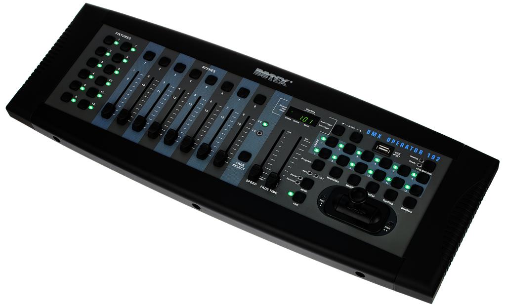
19 Connections and controls 6 Connections and controls 19
20 Connections and controls 1 [FIXTURES] To select the devices relevant for the control. 2 [SCENES] Used for the storage and playback of programmed scenes. 3 Display. The LED display shows you relevant information depending on the respective operation. 4 Buttons for selecting a scene bank or a chase step. Also to view files on a USB flash drive. 5 USB input. 6 Fog machine button. To activate a connected fog machine. 7 Chase buttons For storing and playing chases. 8 Function buttons [Program] To activate and exit the recording mode when programming. [Music/Bkc] To activate the audio mode for chase synchronization and to copy scene banks. 20
21 Connections and controls [Midi/Rec] To record scenes and chase steps. Also for setting the MIDI control. [Auto/Del] To activate the auto mode for automatic scene bank sequences or to delete a scene or a chase. [Tap/Disp] To tap-sync chase playbacks and changing the respective display view. [Blackout] To zero all current output values. 9 Joystick. Usually used to set the X / Y values of the moving light. 10 [MODE] Multifunction button for assigning fader and joystick settings. 11 [FINE] Used in conjunction with the joystick. When the button is pressed, a certain area can be controlled much more precisely with the scanner or the moving light. 21
22 Connections and controls 12 [FADE TIME] Fader to adjust the chase fade time (0 30 seconds) 13 [SPEED] Fader to adjust the chase speed (0.1 seconds 10 minutes per step) 14 [PAGE SELECT] Button to switch between channels 1 8 or Channel fader to control the connected and assigned device. 22
23 Connections and controls 16 [USB] USB connection socket 17 MIDI / DMX operation switch. 18 [AUDIO In] RCA input socket to connect audio equipment for sound control. 19 [DB-9] To connect an optional chase step controller. 23
24 Connections and controls 20 [MIDI In] MIDI input socket. 21 [MIDI Out] MIDI output socket. 22 [FOG MACHINE] To connect a fog machine with analogue interface. 23 [DMX Out] DMX output socket to connect a dimmer or other DMX-controlled devices. 24 [DC In] Connection socket for the 9 V power supply unit. 25 [POWER] Main switch to turn the device on and off. 24
25 Basics 7 Basics This chapter provides basic information about the data transmission using the DMX protocol. Signal transmission DMX signals are generated by a. The signals are transferred over a DMX cable to the connected devices. Each connection can transmit up to 512 channels. For each channel, a value between 0 and 255 is being transmitted. The 512 channels form a so-called DMX universe. Cabling DMX devices are connected serially, that means the sending device transmits signals to all connected receivers (daisy chain). The order of the receivers in the daisy chain does not matter since all devices filter and process the relevant data independently from each other. To create the daisy chain, the DMX input of the first receiver is connected to the DMX output of the controller or another DMX master. The output of the first receiver is connected to the input of the second one, and so on. The output of the last receiver in the DMX chain must be terminated using a resistor (110 Ω, ¼ W). 25
26 Basics If the cable length exceeds 300 m (328 yds.) or the number of devices is greater than 32, the signal must be amplified using a DMX booster. 26
27 Basics Signal processing Each DMX devices operates on a specific number of channels to transfer the incoming control signals into movements, changing of light intensity or colour, and so on. Since all receivers that are part of a DMX daisy chain receive all signals, a start address must be assigned to each DMX device. Starting from this address (a value between 0 and 512) the incoming signals are being evaluated and transferred into the functions of the receiver (internal channel assignment). It is no problem to use a start address more than once in a DMX chain. In that case, the relevant receivers operate synchronously (identical movement, light intensity, colour, and so on). Addressing When setting the DMX address, the counting method of the device determines the first channel. Depending on the device, the channel numbers may start from 0 or from 1. The address range may therefore reach from 0 to 511 or from 1 to
28 Operating 8 Operating 8.1 Manual operation When you turn on the controller, it starts by default in Manual / Blackout mode. All output values are blanked out. To show the values, press [Blackout]. To determine the respective blackout status, there is an indicator in the display that flashes when activated and shows OFF when deactivated. To enable manual operation, turn off Blackout, select the devices to control using the corresponding [FIXTURE] buttons on the left side. Then use the eight channel faders, the joystick and [PAGE SELECT] to manually control the devices. 8.2 Joystick settings Assigning the joystick 1. Keep [Program] pressed for about two seconds or until the PROG indicator flashes on the display. When the indicator flashes, the recording mode is active and you can release the button. 2. Keep [MODE] pressed and press [FINE]. The LEDs for [ASSIGN] and [PAN] should light up now. 28
29 Operating 3. Select the devices you want to assign PAN to. To do so, press the corresponding [FIXTURE] buttons (1 to 12). The LEDs of the selected devices light up. 4. Press [Tap/Disp] to switch between PL.XX and PH.XX. PL.XX stands for the low byte or fine channel, generally listed as the Pan Fine channel. PL.XX stands for the high byte or rough channel, generally listed as the Pan channel. Set PH.XX, press and hold [MODE] and then press the [SCENE] button corresponding to the device's pan channel. For example, if the device's pan channel is 1, you should press the [SCENE] button 1. Please refer to the device's DMX table. If your device has a Pan-Fine channel, press [Tap/Disp] until the display shows PL.XX. Press and hold [MODE] and then press the [SCENE] button corresponding to the device's pan fine channel. For example, if the device's pan fine channel is 2, you should press the [SCENE] button Press the scene bank UP / DOWN buttons to switch between TL.XX and TH.XX. TL.XX stands for the low byte or fine channel, generally listed as the Tilt Fine channel. TH.XX stands for the high byte or rough channel, generally listed as the Tilt channel. Set TH.XX, press and hold [MODE] and then press the [SCENE] button corresponding to the device's tilt channel. For example, if the device's tilt channel is 3, you should press the [SCENE] button 3. Please refer to the device's DMX table. If your device has a Tilt-Fine channel, press [Tap/Disp] until the display shows TL.XX. Press and hold [MODE] and then press the [SCENE] button corresponding to the device's tilt fine channel. For example, if the device's tilt channel is 4, you should press the [SCENE] button 4. 29
30 Operating 6. Keep [Program] pressed for about two seconds or until the PROG indicator stops flashing on the display. As soon as the blackout indicator flashes, the programme mode is deactivated. Assigning the reverse joystick (pan / tilt reversal) 1. Keep [Program] pressed for about two seconds or until the PROG indicator flashes on the display. When the indicator flashes, the recording mode is active and you can release the button. 2. Press and hold [MODE] and press [FINE]. The LEDs for [ASSIGN] and [PAN] should light up now. 3. Press again [MODE] and press [FINE]. The LED for [REVERSE] should light up now. 4. Select the devices you want to assign pan / tilt reversal to. To do so, press the corresponding [FIXTURE] buttons (1 to 12). The LEDs of the selected devices light up. Ideally, you should choose opposing devices for pan / tilt reverse For example, fixtures 1, 3, 5, 7 etc. should be assigned normally. Fixtures 2, 4, 6 etc. should be set up in the reverse direction, so the units will react in the opposite direction when you turn the joystick around. The movement of opposing devices should be in opposite direction. 30
31 Operating 5. Press [Tap/Disp] to switch between PL.XX and PH.XX. PL.XX stands for the low byte or fine channel, generally listed as the Pan Fine channel. PL.XX stands for the high byte or rough channel, generally listed as the Pan channel. Set PH.XX, press and hold [MODE] and then press the [SCENE] button corresponding to the device's pan channel. For example, if the device's pan channel is 1, you should press the [SCENE] button 1. Please refer to the device's DMX table. If your device has a Pan-Fine channel, press [Tap/Disp] until the display shows PL.XX. Keep [MODE] and then press the [SCENE] button corresponding to the device's pan fine channel. For example, if the device's pan fine channel is 2, you should press the [SCENE] button Press the scene bank UP / DOWN buttons to switch between TL.XX and TH.XX. TL.XX stands for the low byte or fine channel, generally listed as the Tilt Fine channel. TH.XX stands for the high byte or rough channel, generally listed as the Tilt channel. Set TH.XX, press and hold [MODE] and then press the [SCENE] button corresponding to the device's tilt channel. For example, if the device's tilt channel is 3, you should press the [SCENE] button 3. Please refer to the device's DMX table. If your device has a Tilt-Fine channel, press [Tap/Disp] until the display shows TL.XX. Keep [MODE] and then press the [SCENE] button corresponding to the device's tilt fine channel. For example, if the device's tilt channel is 4, you should press the [SCENE] button Keep [Program] pressed for about two seconds or until the PROG indicator stops flashing on the display. As soon as the blackout indicator flashes, the programme mode is deactivated. 31
32 Operating Deletion Pan / Tilt joystick settings on selected devices 1. Keep [Program] pressed for about two seconds or until the PROG indicator flashes on the display. When the indicator flashes, the recording mode is active and you can release the button. 2. Keep [MODE] pressed and press [FINE]. The LEDs for [ASSIGN] and [PAN] should light up now. 3. Select the devices you want to delete pan / tilt reversal for. To do so, press the corresponding [FIXTURE] buttons (1 to 12). The assigned LEDs light up. 4. Press and hold [MODE] and press [Auto/Del] to delete the settings of the selected devices. All LEDs flash three times to confirm the deletion. 5. Keep [Program] pressed for about two seconds or until the PROG indicator stops flashing on the display. As soon as the blackout indicator flashes, the programme mode is deactivated. Deletion Pan / Tilt joystick settings on all devices 1. Turn off the controller using the mains switch. 2. Simultaneously press [Auto/Del] and [MODE] and switch the controller back on again. All LEDs flash three times, the settings have been cleared. 32
33 Operating 8.3 Scenes Recording scenes 1. Keep [Program] pressed for about two seconds or until the PROG indicator flashes on the display. When the indicator flashes, the recording mode is active and you can release the button. 2. Select the devices you want to incorporate into your scene. To do so, press the corresponding [FIXTURE] buttons (1 to 12). The LEDs of the selected devices light up. 3. Design your scene using the eight channel faders, the joystick and [PAGE SELECT]. This should be used to switch between channels 1 to 8 and 9 to When you are satisfied with your scene, press [Midi/Rec] to record. 5. Use the scene bank UP / DOWN buttons, select a scene bank for the backup. A total of 30 scene banks are available. These can be seen in the display by looking at the digits on the right outer side. 6. Press one of the [SCENE] buttons (1 to 8) to store. As soon as all the LEDs flash, the scene is saved. Make sure you use a different button each time you save a scene so you do not overwrite what you want to keep. 7. To record additional scenes, repeat steps 2 to 6. 33
34 Operating 8. Keep [Program] pressed for about two seconds or until the PROG indicator stops flashing on the display. As soon as the blackout indicator flashes, the programme mode is deactivated Editing scenes 1. Keep [Program] pressed for about two seconds or until the PROG indicator flashes on the display. When the indicator flashes, the recording mode is active and you can release the button. 2. Use the scene bank UP / DOWN buttons, select the scene bank that contains the scene you want to edit. You can see the active scene bank in the display. 3. Press the [SCENE] button (1 to 8) of the scene you want to edit. 4. Select the device or devices where you want to change the settings for each scene. To do so, press the corresponding [FIXTURE] buttons (1 to 12). The LEDs of the selected devices light up. 5. Use the faders or the joystick to adjust the settings. 6. Press the button [Midi/Rec] and then the [SCENE] button of the scene you want to edit. All LEDs flash three times when the new settings are saved. 34
35 Operating 7. Keep [Program] pressed for about two seconds or until the PROG indicator stops flashing on the display. As soon as the blackout indicator flashes, the programme mode is deactivated Copying a scene 1. Keep [Program] pressed for about two seconds or until the PROG indicator flashes on the display. When the indicator flashes, the recording mode is active and you can release the button. 2. Use the scene bank UP / DOWN buttons to select the scene bank that contains the scene you want to copy. 3. Use the [SCENE] buttons (1 to 8) to select the scene you want to copy. 4. Use the scene bank UP / DOWN buttons to change the scene bank. 5. Press the button [Midi/Rec] and then the [SCENE] button (1 to 8) where you want to copy the scene to. All LEDs flash three times when the scene has been copied. 6. Keep [Program] pressed for about two seconds or until the PROG indicator stops flashing on the display. As soon as the blackout indicator flashes, the programme mode is deactivated. 35
36 Operating Deleting a scene 1. Keep [Program] pressed for about two seconds or until the PROG indicator flashes on the display. When the indicator flashes, the recording mode is active and you can release the button. 2. Use the scene bank UP / DOWN buttons to select the scene bank that contains the scene you want to delete. 3. Press and hold [Auto/Del] and simultaneously press the [SCENE] button (1 to 8) of the scene you want to delete. All LEDs flash three times when the scene has been deleted. 4. Repeat steps 2 and 3 to delete further scenes. 5. Keep [Program] pressed for about two seconds or until the PROG indicator stops flashing on the display. As soon as the blackout indicator flashes, the programme mode is deactivated. 36
37 Operating Deleting all scenes 1. Turn off the controller using the mains switch. 2. Press and hold [Program] while pressing the scene bank AB button and turn the controller back on again. All LEDs flash three times when all scenes have been deleted Scene playback Manual playback 1. When you turn on the controller, it starts by default in Manual / Blackout mode. All output values are blanked out. To show the values, press [Blackout]. To determine the respective blackout status, there is an indicator in the display that flashes when activated and shows OFF when deactivated. Press [Blackout] to stop the display from flashing. 2. Use the scene bank UP / DOWN buttons to select the scene bank that contains the scene you want to play. 3. Use the [SCENE] buttons (1 to 8) to select the scene you want to play. The selected scene is started. Press the same button again to end the scene, or [Blackout] to stop any output. 37
38 Operating 4. Repeat steps 2 and 3 to play additional scenes. Automatic playback 1. Press [Auto/Del]. The indicator for automatic playback in the display lights up. 2. Press the scene bank UP / DOWN buttons to select a desired scene bank for automatic playback. All eight scenes of the selected scene bank are now played one after the other. 3. Using the faders [SPEED] and [FADE] you can adjust the scene playback. You can also press [Tap/Disp] twice to set a number of sequences. The number depends on the bar in which you press [Tap/Disp]. Press again [Auto/Del] to exit the automatic playback mode Audio playback 1. Press [Music/Bkc]. The indicator for automatic playback in the display lights up. 2. Press the scene bank UP / DOWN buttons to select a desired scene bank (1 to 30) or a [CHASE] button (1 to 12). The selected scene bank or chase will start synchronously with the audio playback of the internal microphone or the connected line level input. Press again [Music/Bkc] to exit the audio mode. 38
39 Operating 8.4 Chases Recording chases 1. Keep [Program] pressed for about two seconds or until the PROG indicator flashes on the display. When the indicator flashes, the recording mode is active and you can release the button. 2. To select a chase press the corresponding [CHASE] button (1 to 12). The corresponding LED lights up. 3. Use the scene bank UP / DOWN buttons to first select the desired scene bank and then the scene to be recorded. You can see the scene bank in the display by looking at the digits on the right outer side. You can also adjust the scene using the eight channel faders, the joystick or [PAGE SELECT]. Use [PAGE SELECT] to switch between channels 1 to 8 and 9 to Press [Midi/Rec] to record the chase step. When the chase step is recorded, all LEDs flash three times. 5. Repeat steps 3 and 4 to record further steps. 39
40 Operating 6. Keep [Program] pressed for about two seconds or until the PROG indicator stops flashing on the display. As soon as the blackout indicator flashes, the programme mode is deactivated Recording a scene bank on a chase 1. Keep [Program] pressed for about two seconds or until the PROG indicator flashes on the display. When the indicator flashes, the recording mode is active and you can release the button. 2. To select a chase press the corresponding [CHASE] button (1 to 12). The corresponding LED lights up. 3. Use the scene bank UP / DOWN buttons to select a scene bank to be added to the chase. You can see the scene bank in the display by looking at the digits on the right outer side. 4. Simultaneously press [Music/Bkc] and [Midi/Rec] to include the entire scene bank. When the scene bank is included, all LEDs flash three times. Scenes are included in the same order in which they are stored in the scene bank. 5. Repeat steps 3 and 4 to include further scene banks. 40
41 Operating 6. Keep [Program] pressed for about two seconds or until the PROG indicator stops flashing on the display. As soon as the blackout indicator flashes, the programme mode is deactivated Editing chases Adding a chase step 1. Keep [Program] pressed for about two seconds or until the PROG indicator flashes on the display. When the indicator flashes, the recording mode is active and you can release the button. 2. To select a chase press the corresponding [CHASE] button (1 to 12). The corresponding LED lights up. 3. Press [Tap/Disp], step indicator lights up on the display. 4. Press the scene bank UP / DOWN buttons to move manually through each section of the chase step. Locate the chase step to which you want to add another step. 5. Press [Tap/Disp] to exit the step mode. The step display in the display should then be set to off. 41
42 Operating 6. Use the scene bank UP / DOWN buttons to select the scene bank that contains the scene you want to add. You can see the scene bank in the display by looking at the digits on the right outer side. 7. Press [Midi/Rec] to copy the step into your chase. When the step is added, all LEDs flash three times. 8. Repeat steps 3 to 7 to add further chase steps. 9. Keep [Program] pressed for about two seconds or until the PROG indicator stops flashing on the display. As soon as the blackout indicator flashes, the programme mode is deactivated. Deleting chase steps 1. Keep [Program] pressed for about two seconds or until the PROG indicator flashes on the display. When the indicator flashes, the recording mode is active and you can release the button. 2. To select a chase press the corresponding [CHASE] button (1 to 12). The corresponding LED lights up. 3. Press [Tap/Disp], step indicator lights up on the display. 4. Press the scene bank UP / DOWN buttons to move manually through each section of the chase step. Locate the chase step you want to delete. 42
43 Operating 5. Press the [Auto/Del] to delete the chase step. When the step is deleted, all LEDs flash three times. 6. Repeat steps 4 and 5 to delete further chase steps. 7. Keep [Program] pressed for about two seconds or until the PROG indicator stops flashing on the display. As soon as the blackout indicator flashes, the programme mode is deactivated. Deleting chase 1. Keep [Program] pressed for about two seconds or until the PROG indicator flashes on the display. When the indicator flashes, the recording mode is active and you can release the button. 2. To select a chase press the corresponding [CHASE] button (1 to 12). The corresponding LED lights up. 3. Press and hold [Auto/Del] and press additionally the [CHASE] buttons that you have selected in step 2. When the chase is deleted, all LEDs flash three times. 4. Repeat steps 2 and 3 to delete further chases. 5. Keep [Program] pressed for about two seconds or until the PROG indicator stops flashing on the display. As soon as the blackout indicator flashes, the programme mode is deactivated. 43
44 Operating Deleting all chases 1. Turn off the controller using the mains switch. 2. Press and hold [Program] and the scene bank AB button simultaneously while turning the controller back on again. All LEDs flash three times when all chases have been deleted Playing chases Manual playback 1. When you turn on the controller, it starts by default in Manual / Blackout mode. All output values are blanked out. To show the values, press [Blackout]. To determine the respective blackout status, there is an indicator in the display that flashes when activated and shows OFF when deactivated. Press [Blackout] to stop the display from flashing. 2. Press the [CHASE] button (1 to 12) of the scene you want to play. The corresponding LED lights up. 3. Press the scene bank UP / DOWN buttons to move manually through the chase steps. You can also use the fader [FADE TIME] if you want to have a cross fade between the steps. 4. Repeat steps 2 and 3 to manually play additional scenes. 44
45 Operating Automatic playback 1. Press [Auto/Del]. The indicator for automatic playback in the display lights up. 2. Press the [CHASE] buttons of the chases you want to play. The corresponding LED lights up and playback starts. You can choose more than one chase at a time to create a chase sequence. 3. Using the faders [SPEED] and [FADE] you can adjust the chase playback. You can also press [Tap/Disp] twice to set a number of sequences. The number depends on the bar in which you press [Tap/Disp]. Press again [Auto/Del] to exit the automatic playback mode Audio playback 1. Press [Music/Bkc]. The indicator for automatic playback in the display lights up. 2. Press the [CHASE] buttons (1 to 12) of the chases you want to play. The corresponding LED lights up and playback is started. The selected chase will start synchronously with the audio playback of the internal microphone or the connected line level input. Press again [Music/Bkc] to exit the audio mode. 45
46 Operating 8.5 Copying scene bank and fixtures Copying scene bank 1. Start programme mode. 2. Use the scene bank UP / DOWN buttons, select the scene bank you want to copy. 3. Press [Midi/Rec] and then use the scene bank UP / DOWN buttons to select the scene bank you want to copy to. 4. Press [Music/Bkc]. All LEDs light up three times after copying Copying fixtures 1. Start programme mode. 2. Press the [FIXTURE] button you want to copy. 3. Use the channel faders (1 to 8) or the joystick to set your unit as desired. 46
47 Operating 4. Keep the [FIXTURE] button pressed and then press the [FIXTURE] button to which you want to copy the same settings. 8.6 Fade time 1. Press [MODE] and then [Tap/Disp]. The display now shows ONLY or ALL for 3 seconds, depending on the current settings. ONLY indicates that only the pan / tilt channels are controlled by the [FADE TIME] fader. ALL indicates that all channels are changed by the fader. 2. To switch between ONLY and ALL, press and hold [MODE] while pressing [Tap/Disp]. 47
48 Operating 8.7 MIDI functions MIDI channel setting 1. Keep [Midi/Rec] pressed for two seconds. The display shows the last set MIDI channel. 2. Use the scene UP / DOWN buttons to select a DMX channel that you assign as MIDI channel. 3. Keep [Midi/Rec] pressed for two seconds or until all LEDs light up three times to save the setting. 48
49 Operating Control This unit can receive MIDI data to control or activate scene banks 1 to 30, chases 1 to 12, and the blackout function. Note number Function 00 to 11 Turning chases 1 12 on / off 12 to 19 Turning scenes 1 8 on / off 20 to 49 Selecting scene banks Turning audio on / off 51 Turning auto on / off 52 Turning blackout on / off 49
50 Technical specifications 9 Technical specifications Voltage supply Power adapter (9 V / 500 ma) Connections USB DMX input, DMX output Control DMX512 (192 channels max.) Sound-to-Light Number of cues 240 Dimensions (W H D) 530 mm 120 mm 170 mm Weight 2.8 kg 50

51 Plug and connection assignment 10 Plug and connection assignment Introduction This chapter will help you select the right cables and plugs to connect your valuable equipment so that a perfect light experience is guaranteed. Please take our tips, because especially in Sound & Light caution is indicated: Even if a plug fits into a socket, the result of an incorrect connection may be a destroyed, a short circuit or just a not working light show! DMX socket A female 3-pin XLR socket is used for the DMX output. The figure and the table below show the pin assignment. Pin Assignment 1 Ground (shielding) 2 Signal inverted (DMX, cold ) 3 Signal (DMX+, hot ) 51

. Do not dispose with your normal household waste.")
52 Protecting the environment 11 Protecting the environment Disposal of the packaging material For the transport and protective packaging, environmentally friendly materials have been chosen that can be supplied to normal recycling. Ensure that plastic bags, packaging, etc. are properly disposed of. Do not just dispose of these materials with your normal household waste, but make sure that they are collected for recycling. Please follow the notes and markings on the packaging. Disposal of your old device This product is subject to the European Waste Electrical and Electronic Equipment Directive (WEEE). Do not dispose with your normal household waste. Dispose of this device through an approved waste disposal firm or through your local waste facility. When discarding the device, comply with the rules and regulations that apply in your country. If in doubt, consult your local waste disposal facility. 52
53 Notes 53
54 Notes 54
55
56 Musikhaus Thomann Hans-Thomann-Straße Burgebrach Germany
DMX DC User manual. DMX controller
 User manual Musikhaus Thomann Thomann GmbH Hans-Thomann-Straße 1 96138 Burgebrach Germany Telephone: +49 (0) 9546 9223-0 E-mail: info@thomann.de Internet: www.thomann.de 17.08.2018, ID: 216405 Table of
DMX DC User manual. DMX controller
 User manual Musikhaus Thomann Thomann GmbH Hans-Thomann-Straße 1 96138 Burgebrach Germany Telephone: +49 (0) 9546 9223-0 E-mail: info@thomann.de Internet: www.thomann.de 20.04.2018, ID: 346647 Table of
Achat 115 Sub A active subwoofer. user manual
 Achat 115 Sub A active subwoofer user manual Musikhaus Thomann Thomann GmbH Hans-Thomann-Straße 1 96138 Burgebrach Deutschland Telephone: +49 (0) 9546 9223-0 E-mail: info@thomann.de Internet: www.thomann.de
DSP 18 Sub active subwoofer. user manual
 DSP 18 Sub active subwoofer user manual Musikhaus Thomann Thomann GmbH Hans-Thomann-Straße 1 96138 Burgebrach Germany Telephone: +49 (0) 9546 9223-0 E-mail: info@thomann.de Internet: www.thomann.de 05.11.2018,
FXL8 Pro effects looper. user manual
 FXL8 Pro effects looper user manual Musikhaus Thomann e.k. Treppendorf 30 96138 Burgebrach Germany Telephone: +49 (0) 9546 9223-0 E-mail: info@thomann.de Internet: www.thomann.de 15.09.2014, ID: 337603
Mini Stage Par 4 8W QCL RGBA/RGBW 25 /40 LED PAR. user manual
 Mini Stage Par 4 8W QCL RGBA/RGBW 25 /40 LED PAR user manual Musikhaus Thomann Thomann GmbH Hans-Thomann-Straße 1 96138 Burgebrach Germany Telephone: +49 (0) 9546 9223-0 E-mail: info@thomann.de Internet:
LED Par 36 COB RGBW 12W, LED Par 46 COB RGBW 20W, LED Par 64 COB RGBW 60W, LED Par 56 COB RGBW 30W LED PAR. user manual
 LED Par 36 COB RGBW 12W, LED Par 46 COB RGBW 20W, LED Par 64 COB RGBW 60W, LED Par 56 COB RGBW 30W LED PAR user manual Musikhaus Thomann Thomann GmbH Hans-Thomann-Straße 1 96138 Burgebrach Germany Telephone:
MH-X50+ LED spot moving head. user manual
 MH-X50+ LED spot moving head user manual Musikhaus Thomann e.k. Treppendorf 30 96138 Burgebrach Germany Telephone: +49 (0) 9546 9223-0 E-mail: info@thomann.de Internet: www.thomann.de 02.08.2012 Table
Octagon Theater CW/WW/A 20 6W LED PAR. user manual
 Octagon Theater CW/WW/A 20 6W LED PAR user manual Musikhaus Thomann Thomann GmbH Hans-Thomann-Straße 1 96138 Burgebrach Germany Telephone: +49 (0) 9546 9223-0 E-mail: info@thomann.de Internet: www.thomann.de
LED Pad Bar Compact ST RGB LED lighting set. user manual
 LED Pad Bar Compact ST RGB LED lighting set user manual Musikhaus Thomann Thomann GmbH Hans-Thomann-Straße 1 96138 Burgebrach Germany Telephone: +49 (0) 9546 9223-0 E-mail: info@thomann.de Internet: www.thomann.de
Outdoor Stage PAR 12 4W Quad IR RGBW, 12 3W Quad IR UV LED PAR. user manual
 Outdoor Stage PAR 12 4W Quad IR RGBW, 12 3W Quad IR UV LED PAR user manual Musikhaus Thomann Thomann GmbH Hans-Thomann-Straße 1 96138 Burgebrach Germany Telephone: +49 (0) 9546 9223-0 E-mail: info@thomann.de
Outdoor Stage PAR 12 3W Tri LED PAR. user manual
 Outdoor Stage PAR 12 3W Tri LED PAR user manual Musikhaus Thomann Thomann GmbH Hans-Thomann-Straße 1 96138 Burgebrach Germany Telephone: +49 (0) 9546 9223-0 E-mail: info@thomann.de Internet: www.thomann.de
LED Pot 12 1W RGBW LED PAR. user manual
 LED Pot 12 1W RGBW LED PAR user manual Musikhaus Thomann Thomann GmbH Hans-Thomann-Straße 1 96138 Burgebrach Germany Telephone: +49 (0) 9546 9223-0 E-mail: info@thomann.de Internet: www.thomann.de 31.05.2017,
LED Pot 12 1W QCL RGB WW 15, LED Pot 12 1W QCL RGB WW 40 LED-PAR. user manual
 LED Pot 12 1W QCL RGB WW 15, LED Pot 12 1W QCL RGB WW 40 LED-PAR user manual Musikhaus Thomann Thomann GmbH Hans-Thomann-Straße 1 96138 Burgebrach Deutschland Telephone: +49 (0) 9546 9223-0 E-mail: info@thomann.de
Stage Flood Inst QCL 48x10W LED floodlight. user manual
 Stage Flood Inst QCL 48x10W LED floodlight user manual Musikhaus Thomann Thomann GmbH Hans-Thomann-Straße 1 96138 Burgebrach Germany Telephone: +49 (0) 9546 9223-0 E-mail: info@thomann.de Internet: www.thomann.de
Crown FX PAR 77 LED spotlight. user manual
 Crown FX PAR 77 LED spotlight user manual Musikhaus Thomann Thomann GmbH Hans-Thomann-Straße 1 96138 Burgebrach Germany Telephone: +49 (0) 9546 9223-0 E-mail: info@thomann.de Internet: www.thomann.de 06.02.2018,
LED Flood Panel 150 LED floodlight. user manual
 LED Flood Panel 150 LED floodlight user manual Musikhaus Thomann Thomann GmbH Hans-Thomann-Strasse 1 96138 Burgebrach Germany Telephone: +49 (0) 9546 9223-0 E-mail: info@thomann.de Internet: www.thomann.de
Outdoor Stage PAR 12 3W Tri LED PAR. user manual
 Outdoor Stage PAR 12 3W Tri LED PAR user manual Musikhaus Thomann Thomann GmbH Hans-Thomann-Straße 1 96138 Burgebrach Germany Telephone: +49 (0) 9546 9223-0 E-mail: info@thomann.de Internet: www.thomann.de
LED Bar 240/8 RGB LED floodlight. user manual
 LED Bar 240/8 RGB LED floodlight user manual Musikhaus Thomann Thomann GmbH Hans-Thomann-Straße 1 96138 Burgebrach Germany Telephone: +49 (0) 9546 9223-0 E-mail: info@thomann.de Internet: www.thomann.de
Magic Cube 3D. User manual. effect panel
 Magic Cube 3D User manual Musikhaus Thomann Thomann GmbH Hans-Thomann-Straße 1 96138 Burgebrach Germany Telephone: +49 (0) 9546 9223-0 E-mail: info@thomann.de Internet: www.thomann.de 18.10.2017, ID: 412145
JunoScan MK-II LED scanner. user manual
 JunoScan MK-II LED scanner user manual Musikhaus Thomann Thomann GmbH Hans-Thomann-Straße 1 96138 Burgebrach Germany Telephone: +49 (0) 9546 9223-0 E-mail: info@thomann.de Internet: www.thomann.de 13.08.2015,
Outdoor Stage PAR 12 4 W Quad, 12 3 W UV IR LED PAR. user manual
 Outdoor Stage PAR 12 4 W Quad, 12 3 W UV IR LED PAR user manual Musikhaus Thomann Thomann GmbH Hans-Thomann-Straße 1 96138 Burgebrach Germany Telephone: +49 (0) 9546 9223-0 E-mail: info@thomann.de Internet:
Stage Quad LED Bundle RGBW / RGBWW LED lighting set. user manual
 Stage Quad LED Bundle RGBW / RGBWW LED lighting set user manual Musikhaus Thomann Thomann GmbH Hans-Thomann-Straße 1 96138 Burgebrach Germany Telephone: +49 (0) 9546 9223-0 E-mail: info@thomann.de Internet:
PicoBeam 30 Quad LED moving head
 PicoBeam 30 Quad LED moving head user manual Musikhaus Thomann Thomann GmbH Hans-Thomann-Straße 1 96138 Burgebrach Germany Telephone: +49 (0) 9546 9223-0 E-mail: info@thomann.de Internet: www.thomann.de
JunoScan MK-II LED scanner. user manual
 JunoScan MK-II LED scanner user manual Musikhaus Thomann e.k. Treppendorf 30 96138 Burgebrach Germany Telephone: +49 (0) 9546 9223-0 E-mail: info@thomann.de Internet: www.thomann.de 26.10.2012 Table of
PicoSpot 20 LED moving head. user manual
 PicoSpot 20 LED moving head user manual Musikhaus Thomann Thomann GmbH Hans-Thomann-Straße 1 96138 Burgebrach Germany Telephone: +49 (0) 9546 9223-0 E-mail: info@thomann.de Internet: www.thomann.de 25.01.2017,
Compact LED-Bar 4 TriPAR CLB4 LED lighting set. user manual
 Compact LED-Bar 4 TriPAR CLB4 LED lighting set user manual Musikhaus Thomann Thomann GmbH Hans-Thomann-Straße 1 96138 Burgebrach Germany Telephone: +49 (0) 9546 9223-0 E-mail: info@thomann.de Internet:
SePar QUAD LED RGB UV IR, SePar QUAD LED RGBW LED-PAR. user manual
 SePar QUAD LED RGB UV IR, SePar QUAD LED RGBW LED-PAR user manual Musikhaus Thomann Thomann GmbH Hans-Thomann-Strasse 1 96138 Burgebrach Germany Telephone: +49 (0) 9546 9223-0 E-mail: info@thomann.de Internet:
Stage Flood QCL 24x10W, Stage Flood Inst QCL 24x10W LED floodlight. user manual
 Stage Flood QCL 24x10W, Stage Flood Inst QCL 24x10W LED floodlight user manual Musikhaus Thomann e.k. Treppendorf 30 96138 Burgebrach Germany Telephone: +49 (0) 9546 9223-0 E-mail: info@thomann.de Internet:
RevueLED 120 COB True White LED spotlight. user manual
 RevueLED 120 COB True White LED spotlight user manual Musikhaus Thomann Thomann GmbH Hans-Thomann-Straße 1 96138 Burgebrach Germany Telephone: +49 (0) 9546 9223-0 E-mail: info@thomann.de Internet: www.thomann.de
DJ Lase BlueStar MK-II LED showlaser. user manual
 DJ Lase BlueStar MK-II LED showlaser user manual Musikhaus Thomann Thomann GmbH Hans-Thomann-Straße 1 96138 Burgebrach Germany Telephone: +49 (0) 9546 9223-0 E-mail: info@thomann.de Internet: www.thomann.de
20.12 mixer. user manual
 20.12 mixer user manual Musikhaus Thomann Thomann GmbH Hans-Thomann-Straße 1 96138 Burgebrach Germany Telephone: +49 (0) 9546 9223-0 E-mail: info@thomann.de Internet: www.thomann.de 07.09.2018, ID: 433540
ENGLISH Scanmaster 2 MKII
 MANUAL ENGLISH Scanmaster 2 MKII V1 Highlite International B.V. Vestastraat 2 6468 EX Kerkrade the Netherlands Table of contents Warning...2 Safety Instructions...2 Operating Determinations...3 Connection
Owner s Manual LED COMMANDER 16/2
 Owner s Manual LED COMMANDER 16/2 Content Introduction...2 Technical Specification...2 Maintenance and care...2 Notes on safety...3 Features...4 Overview...5 Installation...6 Operation...6 Channel Assignment...7
Owner s Manual DMX MASTER I & II
 Owner s Manual DMX MASTER I & II Content Introduction...2 Technical Specification...2 Maintenance and care...2 1. Notes on safety...3 2. General Instructions...3 3. Overview...5 4. Operation Guide...7
Star Shot Laser FX. User manual. LED effect
 User manual Musikhaus Thomann Thomann GmbH Hans-Thomann-Straße 1 96138 Burgebrach Germany Telephone: +49 (0) 9546 9223-0 E-mail: info@thomann.de Internet: www.thomann.de 21.02.2018, ID: 416122 Table of
Commander 384. w w w. p r o l i g h t. c o. u k U S E R M A N U A L
 Commander 384 w w w. p r o l i g h t. c o. u k U S E R M A N U A L 1, Before you begin 1.1: Safety warnings...2 3 1.2: What is included...4 1.3: Unpacking instructions...4 2, Introduction 2.1: Features...4
Colour Control48 Order Code: Control48
 Colour Control48 Order Code: Control48 www.cobrainternational.com User Manual Cobra Colour Control 48 Dear Customer, Thank you for purchasing the Cobra Colour Control 48. With decades of experience in
BS-280 R10 BeamSpot moving head
 BS-280 R10 BeamSpot moving head user manual Musikhaus Thomann Thomann GmbH Hans-Thomann-Straße 1 96138 Burgebrach Deutschland Telephone: +49 (0) 9546 9223-0 E-mail: info@thomann.de Internet: www.thomann.de
192 Channel DMX Controller
 DM-X 92 Channel DMX Controller USER MANUAL 54. 9UK Vers ion. D M X 5 2 C O N T R O L L E R S E R I E S Content. Before you begin. What is included.......2 Unpacking instructions....3 Safety instructions...
Dragonfly Quad. User Manual V1.4. Order code: EQLED101
 Dragonfly Quad User Manual V1.4 Order code: EQLED101 Safety advice WARNING FOR YOUR OWN SAFETY, PLEASE READ THIS USER MANUAL CAREFULLY BEFORE YOUR INITIAL START-UP! Before your initial start-up, please
DMX OPERATOR 384 USER S MANUAL
 DMX OPERATOR 384 USER S MANUAL 2015 ADJ Products, LLC all rights reserved. Information, specifications, diagrams, images, and instructions herein are subject to change without notice. ADJ Products, LLC
DMX OPERATOR PRO. User Manual
 User Manual (24-004-1262 Rev 2.0) E-mail: support@elationlighting.com Internet: http://www.elationlighting.com Sections: Table of Contents DMX OPERATOR PRO 1 : General Introduction..... 3 2 : Safety Information
SM DMX LIGHTING CONTROLLER OWNERS MANUAL. May 19, 2009
 SM - 192 DMX LIGHTING CONTROLLER OWNERS MANUAL May 19, 2009 INSTRUCTION MANUAL Page 2 of 8 MAIN FEATURES 192 DMX Channels 30 Scene Banks of 8 programmable scenes each 6 Programmable chases with up to 240
OSO 1612 operator. DMX controller. User manual
 OSO 1612 operator DMX controller User manual Safety instructions WARNING! Always keep this device away from moisture and rain! Hazardous electrical shocks may occur! WARNING! Only connect this device to
Fusion 120 Zoom. User Manual. Order code: EQLED068
 Fusion 120 Zoom User Manual Order code: EQLED068 Safety advice WARNING FOR YOUR OWN SAFETY, PLEASE READ THIS USER MANUAL CAREFULLY BEFORE YOUR INITIAL START-UP! Before your initial start-up, please make
KONTROL channels DMX controller USER MANUAL. For safety, please read this user manual carefully before initial use.
 KONTROL192 192 channels DMX controller USER MANUAL For safety, please read this user manual carefully before initial use. Event Lighting reserves the right to revise the manual at any time. Information
DMX Operator 192-channel lighting controller
 USER MANUAL DMX Operator 192-channel lighting controller CAUTION! Keep this device away from rain and moisture! Unplug mains lead before opening the housing! For your own safety, please read this user
DP-25 digital piano. user manual
 DP-25 digital piano user manual Musikhaus Thomann e.k. Treppendorf 30 96138 Burgebrach Germany Telephone: +49 (0) 9546 9223-0 E-mail: info@thomann.de Internet: www.thomann.de 25.02.2013 Table of contents
DMX192S Controller INSTRUCTION MANUAL. Ref. nr.: V2.1
 DMX192S Controller Ref. nr.: 154.060 INSTRUCTION MANUAL V2.1 2 ENGLISH Congratulations to the purchase of this Beamz product. Please read this manual thoroughly prior to using the product in order to benefit
Stratos Duo RGB. User Manual. Order code: EQLED371
 Stratos Duo RGB User Manual Order code: EQLED1 Safety advice WARNING FOR YOUR OWN SAFETY, PLEASE READ THIS USER MANUAL CAREFULLY BEFORE YOUR INITIAL START-UP! Before your initial start-up, please make
STAGE SETTER-8. User Instructions. Elation Professional 4295 Charter Street Los Angeles Ca
 Introduction STAGE SETTER-8 User Instructions Introduction: Thank you for purchasing the Elation Professional Stage Setter 8. To optimize the performance of this product, please read these operating instructions
Controller DMX DC-1224
 Manual Controller DMX DC-1224 Table of Contents 1. Safety instructions... 4 1.1. FOR SAFE AND EFFICIENT OPERATION... 4 3. Overview... 6 3.1. Front view... 6 3.2. Rear view... 9 4. Operation guide... 10
TRANSCENSION 6-CHANNEL DMX DIMMER PACK (order code: BOTE40) USER MANUAL
 USER MANUAL") www.prolight.co.uk TRANSCENSION 6-CHANNEL PACK (order code: BOTE40) USER MANUAL SAFETY WARNING FOR YOUR OWN SAFETY, PLEASE READ THIS USER MANUAL CAREFULLY BEFORE YOUR INITIAL START-UP! CAUTION! Keep this
www.prolight.co.uk TRANSCENSION 6-CHANNEL PACK (order code: BOTE40) USER MANUAL SAFETY WARNING FOR YOUR OWN SAFETY, PLEASE READ THIS USER MANUAL CAREFULLY BEFORE YOUR INITIAL START-UP! CAUTION! Keep this
DMX48. User s instruction manual. 24 Channel DMX controller
 WWW.LIGHTEMOTIONS.COM.AU DMX48 24 Channel DMX controller User s instruction manual This manual contains important information about the safe installation and use of this product Please read this instruction
ORDER CODE: EQLED65 USER MANUAL
 www.prolight.co.uk ORDER CODE: EQLED65 USER MANUAL Safety WARNING FOR YOUR OWN SAFETY, PLEASE READ THIS USER MANUAL CAREFULLY BEFORE YOUR INITIAL START-UP! CAUTION! Keep this equipment away from rain,
SM-8/2 ORDERCODE 50700
 SM-8/2 ORDERCODE 50700 Congratulations! You have bought a great, innovative product from Showtec. The Showtec SM-8/2 brings excitement to any venue. Whether you want simple plug-&-play action or a sophisticated
2002 Martin Professional A/S, Denmark.
 Freekie user manual 2002 Martin Professional A/S, Denmark. All rights reserved. No part of this manual may be reproduced, in any form or by any means, without permission in writing from Martin Professional
ALO 030 MKII. 30 Watt DMX LED scanner. User manual
 ALO 030 MKII 30 Watt DMX LED scanner User manual Safety instructions WARNING! Always keep this device away from moisture and rain! Hazardous electrical shocks may occur! WARNING! Only connect this device
Spectra Flood Q40. Exterior Fixture User Manual. Order code: LEDJ Version LEDJ284N - 15 Version
 Spectra Flood Q40 Exterior Fixture User Manual Order code: LEDJ284-40 Version LEDJ284N - 15 Version Safety advice WARNING FOR YOUR OWN SAFETY, PLEASE READ THIS USER MANUAL CAREFULLY BEFORE YOUR INITIAL
USER GUIDE 8-CHANNEL DMX CONTROLLER December 2013 Version 1.0 CHASE / STROBE SPEED FADE SPEED RED GREEN BLUE WHITE AMBER DIMMER INSERT
 8-CHANNEL DMX CONTROLLER RED GREEN BLUE YELLOW 1 2 3 4 5 6 CYAN ORANGE PURPLE WHITE RED GREEN BLUE WHITE AMBER DIMMER RECORD INSERT DELETE TAP CLEAR MANUAL MUSIC 1 2 3 5 6 7 AUTO CHASE / STROBE SPEED 4
American DJ DMX OPERATOR
 American DJ DMX OPERATOR User Instructions DMX-512 MIDI C A PA B L E American DJ Los Angeles, CA 90058 - DMX OPERATOR 2000 TABLE OF CTENTS FLOW CHART...3 CTROLS & FUNCTIS...4 REAR CTROLS...6 DMX512 ADDRESSING...6
Spectra Batten (Order code: LEDJ95)
") www.prolight.co.uk Spectra Batten (Order code: LEDJ95) Safety WARNING FOR YOUR OWN SAFETY, PLEASE READ THIS USER MANUAL CAREFULLY BEFORE YOUR INITIAL START-UP! CAUTION! Keep this equipment away from rain,
www.prolight.co.uk Spectra Batten (Order code: LEDJ95) Safety WARNING FOR YOUR OWN SAFETY, PLEASE READ THIS USER MANUAL CAREFULLY BEFORE YOUR INITIAL START-UP! CAUTION! Keep this equipment away from rain,
4LEDKIT-DJ USER MANUAL. LED Tricolor 4-PAR Lighting Kit. Please read this manual carefully and proper take care of this manual.
 4LEDKIT-DJ LED Tricolor 4-PAR Lighting Kit USER MANUAL Please read this manual carefully and proper take care of this manual. Dear customer, First of all thanks for purchasing a SOUNDSATION product. Our
SquareLED - Aura Bar & Matrix Beam Light 100
 SquareLED - Aura Bar & Matrix Beam Light 100 1. SAFETY INSTRUCTIONS Please read these instructions carefully they include the important information about the installation usage and maintenance of this
24 CHANNEL DIMMER CONSOLE USER MANUAL
 PAGE 1 wdmlighting.com CHANNEL DIMMER CONSOLE USER MANUAL WDM LIGHTING 3 OAK LAWN AVE., STE. 1, DALLAS, TX 7519 Improvement and changes to specifications, design and this manual, may be made at any time
STAGE 2412 DMX 24 CHANNELS DMX CONSOLE FOR CONVENTIONAL LIGHTING
 English STAGE 1 DMX User Manual Rev. 11 STAGE 1 DMX CHANNELS DMX CONSOLE FOR CONVENTIONAL LIGHTING This symbol on the product or on its packaging indicates that this product shall not be trated as household
USER'S MANUAL. ADJ R Junostraat EW Kerkrade
 USER'S MANUAL ADJ R Junostraat EW Kerkrade www.adj.com Improvement and changes to specifications, design and this manual, may be made at any time without prior notice. All Rights Reserved Contents Features
GLX DMX-16 MANUAL DMX-16. owners manual
 DMX-16 owners manual Instructions Thanks for choosing the GLX DMX-16 controller. In order to make the best use of your GLX controller, please read the following carefully. The DMX-16 is a standard universal
LIGHT COPILOT II. elationlighting.com Internet:
 LIGHT COPILOT II E-mail: info@ elationlighting.com Internet: http://www.elationlighting.com 1 Introduction Thank you for your purchase of the LIGHT COPILOT II. The LIGHT COPILOT II is an intelligent lighting
English. Light Operator 24 USER'S MANUAL. Please read before use
 English Light Operator USER'S MANUAL Please read before use Contents Light Operator Improvement and changes to specifications, design and this manual, may be may at any time without prior notice. All rights
Mini LED Pin Spot Light Model: PLS00571
 Mini LED Pin Spot Light Model: PLS00571 1 Please read these instructions carefully before use and retain for future reference. IMPORTANT SAFETY INFORMATION When using electrical appliances basic safety
PLAYMATE PROFESSIONAL STEREO 19 MIXER, USB/SD CARD AND BLUETOOTH PLAYER. User Guide and Reference Manual. page 1
 PLAYMATE PROFESSIONAL STEREO 19 MIXER, USB/SD CARD AND BLUETOOTH PLAYER User Guide and Reference Manual page 1 INTRODUCTION Congratulations and thank you for purchasing the NewHank Playmate mixer. This
Techni-Lux. COMMANDER 24&48 24&48 Ch DMX Controllers USER'S MANUAL. Please read before use V1.1
 Techni-Lux COMMANDER & & Ch DMX Controllers USER'S MANUAL Please read before use V1.1 COMMANDER & & Ch DMX Controllers Improvement and changes to specifications, design and this manual, may be made at
4-PROJECTOR BAR WITH 3 X 9W LEDS AND 1 X 1W FLASH LED USER GUIDE
 4-PROJECTOR BAR WITH 3 X 9W LEDS AND 1 X 1W FLASH LED USER GUIDE 10482 - Version 1 / 04-2016 English LIVESET - LIVESET - 4-Projector bar with 3 x 9W LEDs and 1 x 1W Flash LED 1 - Safety information Important
Stage Wash 7x 10W LED Moving Head (RGBW)
") Stage Wash 7x 10W LED Moving Head (RGBW) P/N 612870 User's Manual CONTENTS SAFETY WARNINGS AND GUIDELINES... 3 INTRODUCTION... 4 FEATURES... 5 CUSTOMER SERVICE... 5 PACKAGE CONTENTS... 6 PRODUCT OVERVIEW...
Stage Wash 7x 10W LED Moving Head (RGBW) P/N 612870 User's Manual CONTENTS SAFETY WARNINGS AND GUIDELINES... 3 INTRODUCTION... 4 FEATURES... 5 CUSTOMER SERVICE... 5 PACKAGE CONTENTS... 6 PRODUCT OVERVIEW...
Snapshot. Obey 10 DMX Controller USER MANUAL
 Obey 10 DMX Controller Snapshot Ok on Dimmer Outdoor OK Sound Activated DMX512 Master/Slave 115V/230V Switch Replaceable Fuse User Serviceable Duty Cycle USER MANUAL Chauvet, 3000 N 29 th Ct, Hollywood,
User Instructions. Warning! To prevent or reduce the risk of electrical shock or fire, do not expose this unit to rain or moisture.
 General Information User Instructions Unpacking: Thank you for purchasing the by American DJ. Every has been thoroughly tested and has been shipped in perfect operating condition. Carefully check the shipping
DMX-7 USER MANUAL. Universal DMX Controller
 DMX-7 Universal DMX Controller USER MANUAL Chauvet, 3000 N 29 th Ct, Hollywood, FL 33020 U.S.A (800) 762-1084 (954) 929-1115 FAX (954) 929-5560 www.chauvetlighting.com 2006-03-20/15:55 TABLE OF CONTENT
User Instructions. Warning! To prevent or reduce the risk of electrical shock or fire, do not expose this unit to rain or moisture.
 General Information User Instructions Unpacking: Thank you for purchasing the by American DJ. Every has been thoroughly tested and has been shipped in perfect operating condition. Carefully check the shipping
ALO 060 DMX LED scanner
 ALO 060 DMX LED scanner User manual Safety instructions WARNING! Always keep this device away from moisture and rain! Hazardous electrical shocks may occur! WARNING! Only connect this device to a matching
Professional RGB LED DMX Controller
 Professional RGB LED DMX Controller LC-8PRO Order No. 38.0010 INSTRUCTION MANUAL ELECTRONICS FOR SPECIALISTS ELECTRONICS FOR SPECIALISTS ELECTRONICS FOR SPECIALISTS ELECTRONICS FOR SPECIALISTS Warning...
USER MANUAL Table of Contents
 USER MANUAL Table of Contents Safety Information. 3 Specifications.. 4 Main Power Connection.. 5 DMX-512 Connection...... 5 Main Control Menu... 6 Fixture Addressing... 6 Manual Mode...7 Save Scene...7
Showdesigner 1024 ORDERCODE 50720
 Showdesigner 1024 ORDERCODE 50720 Congratulations! You have bought a great, innovative product from Showtec. The Showtec Showdesigner 1024 brings excitement to any venue. Whether you want simple plug-&-play
LED Thunder S-150 Code 1097
 LED Thunder S-150 Code 1097 User Manual 1 1 SAFETY INSTRUCTIONS This device has left the factory in perfect condition. In order to maintain this condition and to ensure a safe operation, it is absolutely
1ENGLISH P R O Thanks for your reliability on us having acquired a product WORK. We hope it provides you a long and reliable service. The STAGE is a l
 LIGHTING CONTROL MIXER P R O STAGE 1 DMX R STAGE DMX OPERATING INSTRUCTIONS 1ENGLISH P R O Thanks for your reliability on us having acquired a product WORK. We hope it provides you a long and reliable
User Instructions. Warning! To prevent or reduce the risk of electrical shock or fire, do
 7/07 User Instructions American DJ 4295 Charter Street Los Angeles Ca. 90058 www.americandj.com Introduction Unpacking: Thank you for purchasing the by American DJ. Every has been thoroughly tested and
Manual. Kingpad mc-edition light-module. Bus system control pad for installation in the Graupner mc-16 / mc-20 / mc-26 / mc-28 transmitter
 EN Manual Kingpad mc-edition light-module Bus system control pad for installation in the Graupner mc-16 / mc-20 / mc-26 / mc-28 transmitter No. 3974.1 Use example Copyright Graupner/SJ GmbH 2 / 16 Index
Show Designer 3. Software Revision 1.15
 Show Designer 3 Software Revision 1.15 OVERVIEW... 1 REAR PANEL CONNECTIONS... 1 TOP PANEL... 2 MENU AND SETUP FUNCTIONS... 3 CHOOSE FIXTURES... 3 PATCH FIXTURES... 3 PATCH CONVENTIONAL DIMMERS... 4 COPY
TL5024 MEMORY LIGHTING CONSOLE OWNERS MANUAL. Version 1.01
 TL5024 MEMORY LIGHTING CONSOLE OWNERS MANUAL Version 1.01 09/22/2017 Page 2 of 14 SPECIFICATIONS Total channels Operating modes Scene memory Chase 12 or 24 depending on mode 12 channels x 2 manual scenes
STAGE 250. Owner s Manual TRANSPORTABLE PA WITH BUILT-IN MIXER AND 24 BIT EFFECTS
 STAGE 250 Owner s Manual TRANSPORTABLE PA WITH BUILT-IN MIXER AND 24 BIT EFFECTS Important Safety Instructions For your own safety you must read this section in full first! Intended use This device is
VGAD-12 ORDERCODE
 VGAD-12 ORDERCODE 101220 Congratulations! You have bought a great, innovative product from DMT. The DMT Media Spinner brings excitement to any venue. Whether you want simple plug-&-play action or a sophisticated
FD Trinitron Colour Television
 R 4-205-569-32(1) FD Trinitron Television Instruction Manual GB KV-14LM1U 2000 by Sony Corporation NOTICE FOR CUSTOMERS IN THE UNITED KINGDOM A moulded plug complying with BS1363 is fitted to this equipment
LED Beam Moving Head. TWIST-150LED Order No INSTRUCTION MANUAL
 LED Beam Moving Head TWIST-150LED Order No. 38.7970 INSTRUCTION MANUAL MONACOR INTERNATIONAL GmbH & Co. KG Zum Falsch 36 28307 Bremen Germany www.monacor.com 01.30.11.2016 ELECTRONICS FOR SPECIALISTS ELECTRONICS
Hex-color RGBAW+UV LED strip light
 Hex-color RGBAW+UV LED strip light 2 19 SAFETY / GENERAL INSTRUCTIONS INTRODUCTION Features Specifications OVERVIEW : CONNECTIONS Rear view DIMENSIONS INSTALLATION Mounting FUNCTIONS AND SETTINGS Function
Ambient Temperature...3 Electromagnetic Compliance...3
 TABLE OF CONTENTS: SAFETY AND SERVICE... 2 Operational Safety... 2 Location... 2 Ambient Temperature...3 Electromagnetic Compliance...3 Service... 3 Cleaning... 3 Package Contents... 4 Specifications...
LED-BANK4 USER MANUAL. COLORbank 4
 LED-BANK4 COLORbank 4 USER MANUAL CHAUVET, 3000 N 29 th Ct, Hollywood, FL 33020 U.S.A (800) 762-084 (954) 929-5 FAX (954) 929-5560 www.chauvetlighting.com 2006-04-8/6:44 Table of Content BEFORE YOU BEGIN...
User Manual. Xstatic Pro, Inc Essex Street - Brooklyn, NY Version 1.2
 User Manual 0 19372 40968 7 Xstatic Pro, Inc. - 901 Essex Street - Brooklyn, NY 11208 718.237.2299 Version 1.2 NOTICE: 2018 Xstatic Pro, Inc. All rights reserved. ProX Lighting believes that the information
CLF Manuals CLF Colour Par CLF Colour 12 Par CLF Colour Par 12 Version 1.0 November 2012 Version 1.0 1
 CLF Manuals CLF Colour Par 12 CLF Colour Par 12 Version 1.0 November 2012 1 1.BEFORE YOU BEGIN What is included Ø 1 x Fixture Ø 1 x Power cable with plug Ø 1 x User Manua Unpacking Instructions Immediately
SyncGen. User s Manual
 SyncGen User s Manual 1 IMPORTANT SAFETY INSTRUCTION READ FIRST This symbol, whenever it appears, alerts you to the presence of uninsulated dangerous voltage inside the enclosure-voltage that may be sufficient