Nixie Clock Type Quattro'
|
|
|
- Stewart Golden
- 5 years ago
- Views:
Transcription


1 Assembly Instructions And User Guide Nixie Clock Type Quattro' - 1 -
2 Issue Number Date REVISION HISTORY 2 8 Sept 2012 Errors corrected 1 27 July 2012 New document Reason for Issue - 2 -
3 1.1 Nixie Quattro - Features Nixie clock type Nixie Quattro has the following features: - Hours, Minutes and Seconds display - 12 or 24 hour modes - Uses a Quartz Crystal Oscillator as the timebase - Programmable leading zero blanking - Supercapacitor backup. Keeps time during short power outages - Simple time setting using two buttons - Programmable leading zero blanking - Five programmable neon colon settings (Flashing AM/PM indication, illuminated AM/PM indication, both flashing, both on, both off) - Seconds can be reset to zero to precisely the set time - Programmable night mode - blanked or dimmed display to save tubes or prevent sleep disturbance. - Separate modes for colon neons during night mode - Standard, or scrollback display modes - Slot Machine Cathode poisoning prevention routine - Not AC frequency dependent works in all countries - All user preferences stored to non-volatile memory - 3 -
4 1.3 SAFETY DANGER: The clock pcb includes a switched-mode voltage booster circuit. This generates nominally 170 Volts DC. Assembly may only be undertaken by individuals who are suitably qualified and experienced in electronics assembly, and are familiar with safe procedures for working with high voltages. If in doubt, refer to a suitably qualified engineer before proceeding. The voltages generated by this circuit can give a potentially LETHAL ELECTRIC SHOCK. DISCLAIMER: This product is supplied as a kit of parts, intended only for suitably qualified electronic engineers, who are suitably qualified and experienced in electronics assembly, and are familiar with safe procedures for working with high voltages. The supplier, his agents or associates accept no liability for any damage, injury or death arising from the use of this kit of parts. This is not a finished product, and the person assembling the kit is responsible for ensuring that the finished product complies with any applicable local regulations governing electrical equipment, eg. UL, CE, VDE
5 - 5 -
6 2. LIST OF COMPONENTS 2.1 Table of Components Circuit Designation Part Description Resistors R1 4.7 KΩ, ¼ Watt R2 390 KΩ, ¼ Watt R3 4.7 KΩ, ¼ Watt R4 390 KΩ, ¼ Watt R5 - R8 4.7 KΩ, ¼ Watt R9 - R KΩ, ¼ Watt R13 R17 10 KΩ, ¼ Watt R KΩ, ¼ Watt R19, R Ω, ¼ Watt Capacitors C1, C2 100nF Ceramic C3 1uF, 250V, Electrolytic C4 470uF, 16-25V, Electrolytic C5 15pF Ceramic C6 33pF Ceramic C7 100nF Ceramic C8 0.1F C9 100nF Transistors Q1 IRFD220 MOSFET Q2, Q3 MPSA42 Q4, Q5 MPSA92 Q6, Q7 MPSA42 Diodes D1 D3 1N5819 D4 UF4004 D5 - D8 3mm Blue LED ZD1 62V Zener diode Integrated Circuits IC1 78L05 5V voltage regulator IC2 PIC16F bit microcontroller IC3 HV5812 Miscellaneous L1 100uH inductor PM 4mm wire ended neon lamp SET, ADJ Miniature push button IC2 Socket 18 Way narrow IC socket for IC2 IC3 Socket PLCC28 IC socket for IC3 FUSE 500mA fuse Insulation Clear insulation for PM neon NX1 NX4 Z5700M Nixie Tube X KHz watch crystal - 6 -
7 2.2 Parts list / Packing Sheet Part Description Quantity Resistors 270 Ω, ¼ Watt KΩ, ¼ Watt 6 10 KΩ, ¼ Watt KΩ, ¼ Watt 7 Capacitors 33pF, Ceramic 1 15pF, Ceramic 1 100nF, Ceramic 4 1uF, 250V, Electrolytic 1 470uF, 16-25V, Electrolytic 1 0.1F 1 Transistors IRFD220 MOSFET 1 MPSA42 4 MPSA92 2 Diodes 1N UF4004 fast recovery diode 1 3mm Blue LED 4 62V Zener diode 1 Integrated Circuits 78L05 5V voltage regulator 1 PIC16F bit microcontroller 1 HV Miscellaneous 100uH inductor 1 4mm wire ended neon lamp 1 Miniature push button 2 18 way narrow IC Socket for IC2 1 PLCC28 IC Socket for IC mm PCB power socket 1 500mA fuse 1 Clear insulation for neons KHz watch crystal 1-7 -


8 Quick Assembly Guide 1.0 Low Voltage Components: J1, Fuse, D1 - D3, C1, C2, IC1. Test 5V test point for V 1.1 High Voltage Components: C3, C4, R1- R4, D4, L1, ZD1, Q1, IC2 / IC2 socket The two joined pins on Q1 face the inductor. Test HV Point for V 1.2 All remaining components except Tubes and LEDs 1.3 Z570M, Z573M, ZM1080, ZM1082, GN9A Nixie Tubes. It is necessary to clip off two of the Z570M and equivalent tube leads: Clip off the two leads as shown below: This is how the tube will look after removing the leads: - 8 -

9 To facilitate easy insertion of the flying leads into the PCB holes, it helps enormously to trim the remaining flying leads with a pair of scissors as shown below. Start at one of the leads at the back of the tube. Then, working around the tube, cut each sucessive lead approx 2mm shorter than the previous one. This will allow you to feed each lead in in turn. Now you can insert and solder in the tube. 1.4 D5 - D8-9 -
10 10. HOW TO OPERATE THE CLOCK The twp buttons have the following functions: SET: Set time and date; Enter configuration menu; ADJ: Adjust: time, adjust configuration values. Entering configuration mode: The principal settings of the clock are stored in flash memory your preferred configuration is stored even after powering off the clock for extended periods. To access the configuration mode press and hold the SET button. After 2 seconds the seconds will display. Continue holding the button a further 2 seconds until the clock displays in this format: 01-XX. XX is the software verson. eg. 12 means version 1.2 In configuration mode the hours digits diplay the current parameter being adjusted, and the minutes digits display the current value stored against the parameter. For each parameter, and referring to the table below, scroll through the range of possible values by pressing the ADJ button. When the desired value has been reached, move on to the next parameter by pressing the SET button. When the last parameter has been set, pressing SET one more time will revert the clock back to time display mode. The first parameter (0) cannot be changed as it is the software revision number. It will show for several seconds and then move to parameter 1. In all correspondence on support issues, please quote the board type, revision date and software version
11 Parameter Description Values 0 Software revision 10 = version 1.0, 11 = version 1.1 etc 1 12 / 24 Hr mode 0 12 Hr (default) 1 24 Hr 2 Leading zero blanking eg. 01:54:32 0 leading zero blanked (default) 1 leading zero displayed 3 Night Mode start hour Night Mode end hour 0-23 Notes: 5 Night Mode 0 Tubes off 1 Dimmed display (default) 6 PM neon mode 0 AM/PM Indication, flashing 1 AM/PM Indication, illuminated 2 Flashing (default) 3 Illuminated 4 Off 7 PM neon during night dimmed mode 1 0 AM/PM Indication, flashing 1 AM/PM Indication, illuminated 2 Flashing 3 Illuminated (default) 4 Off 0-9 (default 9) 8 LED Tube Lighting Brightness 9 LED Tube Lighting 0-9 (default 3) Brightness (Night Mode) 10 Reserved leave as Reserved leave as Slots Mode 2 0 Slots disabled 1 Slots every minute 2 - Slots every 10 minutes (default) 3 - Slots every hour 4 Slots at midnight 13 Display Mode 0 Standard change of digits 1 Cross-fading digits with scrollback effect (default) 14 Seconds display each minute 0 Off 1 On (default) 3 15 Night Mode Override Period 0 50 (default 0 gives 15 seconds override) 4 15 Restore default settings 0 Keep user settings 1 Restore original default settings 5 1. Night time neon mode is active when night mode is set to dim. During night time blanking the tubes AND PM neon are disabled. 2. Visual effect / cathode poisoning prevention all digits on all tubes are cycled for 10 seconds. Not active during night blanking or dimmed modes. 3. Seconds will be displayed each minute between 55 and 59 seconds past the minute. 4. Press SET briefly during Night Mode to show time for prescribed period. 5. Set this parameter to 1 to restore original default settings. Internal operations will then load all the original settings and restore the value to
12 Setting the Time and Date: From time display mode, press and hold SET button for 2 seconds until the seconds digits are displayed Press the ADJ button to reset seconds to zero. Briefly Press SET again and the minutes will be highlighted Press the ADJ button to set the minutes. Briefly Press SET again and the hours will be highlighted. Press the ADJ button to set the hours. Finally, briefly Press SET again to revert to normal clock operation. Auto Date Display: Setting parameter (14) to 1 will enable auto display of date between 55 and 59 seconds past each minute. Night Blanking Override: During programmed night blanking, the blanking may be overridden to see the time by briefly pressing the SET button. Tubes will remain lit for the period defined in parameter (15)

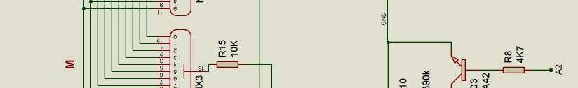
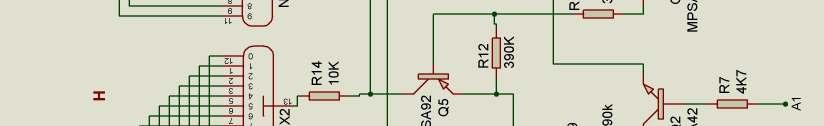
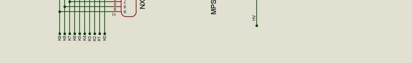
13 13. CIRCUIT DIAGRAM
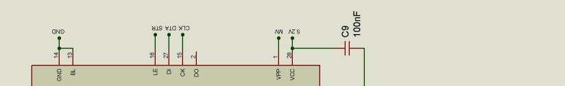
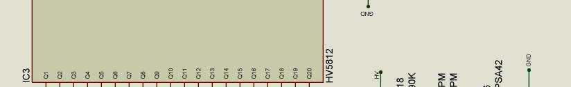
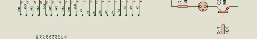
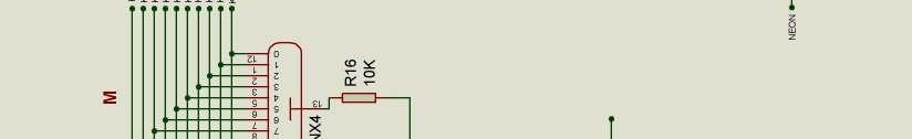

14 - 14 -
Assembly Instructions And User Guide. Nixie FunKlock. FunKlock Issue 4 (1 February 2017)
") Assembly Instructions And User Guide Nixie FunKlock - 1 - Issue Number Date REVISION HISTORY 4 1 February 2017 New diode for D2 3 27 December 2013 C7 / C8 error page 15 2 7 November 2013 Errors corrected
Assembly Instructions And User Guide Nixie FunKlock - 1 - Issue Number Date REVISION HISTORY 4 1 February 2017 New diode for D2 3 27 December 2013 C7 / C8 error page 15 2 7 November 2013 Errors corrected
Nixie Clock Type Frank 2 Z570M
 Assembly Instructions And User Guide Nixie Clock Type Frank 2 Z570M Software version: 7R PCB Revision: 11 April 09-1 - 1. INTRODUCTION 1.1 About the clock Nixie clock type Frank 2 is a compact design with
Nixie Clock Type Frank 3'
 Assembly Instructions And User Guide Nixie Clock Type Frank 3' - 1 - REVISION HISTORY Issue Number Date Reason for Issue 4 16 December 2016 New diode for D2 3 12 November 2012 Improved first clock test
Nixie Clock Type Frank 3
 Assembly Instructions And User Guide Nixie Clock Type Frank 3 Software version: 7R PCB Version: 11 April 09-1 - 1. INTRODUCTION 1.1 About the clock Nixie clock type Frank 3 is a compact design with all
Nixie Clock Type IN-8 & NL840 Nixie'
 Assembly Instructions And User Guide Nixie Clock Type IN-8 & NL840 Nixie' - 1 - REVISION HISTORY Issue Number Date 4 15 December 2016 New diode for D2 3 30 August 2014 Typos 2 25 June 2014 Added NL840
SN-Class Nixie Clock Kits
 Assembly Instructions And User Guide SN-Class Nixie Clock Kits - 1 - REVISION HISTORY Issue Date Reason for Issue Number 1 20 November 2017 New document - 2 - 1. INTRODUCTION 1.1 About the How can the
Nixie Clock Type Nixie QTC
 Assembly Instructions And User Guide Nixie Clock Type Nixie QTC - 1 - REVISION HISTORY Issue Number Date Reason for Issue 12 10 September 2015 C6 changed to 33pF 11a 11 December 2014 C5 changed to 10pF.
Nixie Clock Type SixNix
 Assembly Instructions And User Guide Nixie Clock Type SixNix - 1 - Issue Number Date REVISION HISTORY Reason for Issue 6 20 March 2014 Removed WWVB Support 5 14 July 2012 New Board Issue - 19 July 12 4
Nixie Clock Type Nixie Maestro
 Assembly Instructions and User Guide Nixie Clock Type Nixie Maestro - 1 - Issue Number Date REVISION HISTORY Reason for Issue 4 01 April 2017 New version with neons for AM / PM 3 10 December 2014 Typing
Nixie Tube Clock Type Marsden
 Assembly Instructions And User Guide Nixie Tube Clock Type Marsden Software version: RTC-1.3 PCB Revision: 16 Aug 10-1 - 1. INTRODUCTION 1.1 About the clock Nixie clock type Marsden is a compact design
Nixie Clock Type Nixie QTC Plus
 Assembly Instructions And User Guide Nixie Clock Type Nixie QTC Plus - 1 - REVISION HISTORY Issue Date Number Draft 1 29 August 2018 New document Reason for Issue - 2 - 1. INTRODUCTION 1.1 Nixie QTC Plus
Assembly Instructions And User Guide. Elite Nixie. Nixie Tube Clock Elite Issue 2 (07 June 2018)
") Assembly Instructions And User Guide Elite Nixie - 1 - REVISION HISTORY Issue Number Date Reason for Issue 2 07 June 2018 Added more NL840 details 1 04 May 2018 New document - 2 - 1. INTRODUCTION Here
Assembly Instructions And User Guide Elite Nixie - 1 - REVISION HISTORY Issue Number Date Reason for Issue 2 07 June 2018 Added more NL840 details 1 04 May 2018 New document - 2 - 1. INTRODUCTION Here
Nixie Clock Kit V1.08 Assembly and Operation
 Nixie Clock Kit V1.08 Assembly and Operation Hardware Revision 14.05.2005 Software Version 6.0 Revision 19.04.2006 This document is copyrighted. No parts of this documentation may be used commercially.
Documentation VFD clock 8 a clock
 Documentation VFD clock 8 a clock This documentation is protected by our copyright. It must not be used for commercial purposes. Congratulations on your purchase of your VFD clock. To guarantee success
16 Stage Bi-Directional LED Sequencer
 16 Stage Bi-Directional LED Sequencer The bi-directional sequencer uses a 4 bit binary up/down counter (CD4516) and two "1 of 8 line decoders" (74HC138 or 74HCT138) to generate the popular "Night Rider"
Arduino Nixie Clock Classic Rev4 and Rev5 All In One Modular Rev2
 Arduino Nixie Clock Classic Rev4 and Rev5 All In One Modular Rev2 Operating Instructions Firmware V47 Supported Models: Classic Rev4 Classic Rev5 Modular Rev2 All-In-One NixieClockUserManualV47 About this
Arduino Nixie Clock Classic Rev4 and Rev5 All In One
 Arduino Nixie Clock Classic Rev4 and Rev5 All In One Operating Instructions Firmware V52 Supported Models: Classic Rev4 Classic Rev5 All-In-One NixieClockUserManualV52 About this document This is the user
Arduino Nixie Clock Modular Rev3
 Arduino Nixie Clock Modular Rev3 Operating Instructions Firmware V348 Supported Models: Modular Revision 3 NixieClockUserManualV348 About this document This is the user instruction manual for the Nixie
7 SEGMENT LED DISPLAY KIT
 ESSENTIAL INFORMATION BUILD INSTRUCTIONS CHECKING YOUR PCB & FAULT-FINDING MECHANICAL DETAILS HOW THE KIT WORKS CREATE YOUR OWN SCORE BOARD WITH THIS 7 SEGMENT LED DISPLAY KIT Version 2.0 Which pages of
DDS VFO CONSTRUCTION MANUAL. DDS VFO Construction Manual Issue 1.1 Page 1
 DDS VFO CONSTRUCTION MANUAL DDS VFO Construction Manual Issue 1.1 Page 1 Important Please read before starting assembly STATIC PRECAUTION The DDS VFO kit contains the following components which can be
Introduction 1. Green status LED, controlled by output signal ST. Sounder, controlled by output signal Q6. Push switch on input D6
 Introduction 1 Welcome to the GENIE microcontroller system! The activity kit allows you to experiment with a wide variety of inputs and outputs... so why not try reading sensors, controlling lights or
8 PIN PIC PROGRAMMABLE BOARD (DEVELOPMENT BOARD & PROJECT BOARD)
") ESSENTIAL INFORMATION BUILD INSTRUCTIONS CHECKING YOUR PCB & FAULT-FINDING MECHANICAL DETAILS HOW THE KIT WORKS LEARN ABOUT PROGRAMMING WITH THIS 8 PIN PIC PROGRAMMABLE BOARD (DEVELOPMENT BOARD & PROJECT
ESSENTIAL INFORMATION BUILD INSTRUCTIONS CHECKING YOUR PCB & FAULT-FINDING MECHANICAL DETAILS HOW THE KIT WORKS LEARN ABOUT PROGRAMMING WITH THIS 8 PIN PIC PROGRAMMABLE BOARD (DEVELOPMENT BOARD & PROJECT
WiFi Time Provider v1 for Arduino Nixie Clock Operating Instructions & Construction Manual
 WiFi Time Provider v1 for Arduino Nixie Clock Operating Instructions & Construction Manual Document V001c Contact Information If you want to get in contact with us, please email to: nixie@protonmail.ch
Nixie Clock Kit IN-12B color LED backlit Operation Manual Nixie Clock Kit IN-12B V6.0 ( All Right Reserved 2015 )
") Nixie Clock Kit IN-B color LED backlit Operation Manual Nixie Clock Kit IN-B V. ( All Right Reserved ) - - Operation Manual IN-B Nixie Clock Power for your Nixie Clock The clock does not include a wall
Nixie Clock Kit IN-B color LED backlit Operation Manual Nixie Clock Kit IN-B V. ( All Right Reserved ) - - Operation Manual IN-B Nixie Clock Power for your Nixie Clock The clock does not include a wall
Arduino Nixie Clock Modular Rev3
 Arduino Nixie Clock Modular Rev3 Operating Instructions Firmware V352 Supported Models: Modular Revision 3 NixieClockUserManualV352 About this document This is the user instruction manual for the Nixie
Timer Modules. MEU11 24 Hour Module, MEU17 7 Day Module (Without Housing)
") Timer Modules MEU11 24 Hour Module, MEU17 7 Day Module (Without Housing) EMU11 24 Hour Module, EMU17 7 Day Module (With Housing Giving panel mounting facility) Installation & Operating Instructions 1 1.
Timer Modules MEU11 24 Hour Module, MEU17 7 Day Module (Without Housing) EMU11 24 Hour Module, EMU17 7 Day Module (With Housing Giving panel mounting facility) Installation & Operating Instructions 1 1.
Digital Clock. Perry Andrews. A Project By. Based on the PIC16F84A Micro controller. Revision C
 Digital Clock A Project By Perry Andrews Based on the PIC16F84A Micro controller. Revision C 23 rd January 2011 Contents Contents... 2 Introduction... 2 Design and Development... 3 Construction... 7 Conclusion...
MONO AMPLIFIER KIT ESSENTIAL INFORMATION. Version 2.2 CREATE YOUR OWN SPEAKER DOCK WITH THIS
 ESSENTIAL INFORMATION BUILD INSTRUCTIONS CHECKING YOUR PCB & FAULT-FINDING MECHANICAL DETAILS HOW THE KIT WORKS CREATE YOUR OWN SPEAKER DOCK WITH THIS MONO AMPLIFIER KIT Version 2.2 Build Instructions
Christmas LED Snowflake Project
 Christmas LED Snowflake Project Version 1.1 (01/12/2008) The snowflake is a follow-on from my Christmas star project from a few years ago. This year I decided to make a display using only white LEDs, shaped
Reaction Game Kit MitchElectronics 2019
 Reaction Game Kit MitchElectronics 2019 www.mitchelectronics.co.uk CONTENTS Schematic 3 How It Works 4 Materials 6 Construction 8 Important Information 9 Page 2 SCHEMATIC Page 3 SCHEMATIC EXPLANATION The
Arduino IN-14 Nixie Clock v42 All-In-One Clock Operating Instructions & Construction Manual
 Arduino IN-14 Nixie Clock v42 All-In-One Clock Operating Instructions & Construction Manual NixieClockIN14InstructionManualRev2V42 Contact Information If you want to get in contact with us, please email
DIY KIT MHZ 8-DIGIT FREQUENCY METER
 This kit is a stand-alone frequency meter capable of measuring repetitive signals up to a frequency of 50MHz. It has two frequency ranges (15 and 50 MHz) as well as two sampling rates (0.1 and 1 second).
N3ZI Digital Dial Manual For kit with Backlit LCD Rev 4.00 Jan 2013 PCB
 N3ZI Digital Dial Manual For kit with Backlit LCD Rev 4.00 Jan 2013 PCB Kit Components Item Qty Designator Part Color/Marking PCB 1 LCD Display 1 LCD 1602 Volt Regulator 1 U1 78L05, Black TO-92 Prescaler
Arduino Modular IN-14 Nixie Clock Rev2 V45 All-In-One Modular Clock Operating Instructions & Construction Manual
 Arduino Modular IN-14 Nixie Clock Rev2 V45 All-In-One Modular Clock Operating Instructions & Construction Manual NixieClockModularInstructionManualRev2V45 Contact Information If you want to get in contact
Bill of Materials: Super Simple Water Level Control PART NO
 Super Simple Water Level Control PART NO. 2169109 Design a simple water controller in which electrodes are required to sense high and low water levels in a tank. Whenever the water level falls below the
GUIDE TO ASSEMBLY OF ERICA SYNTHS DELAY MODULE
 If you are reading this, most probably, you are about to build Erica Synths DIY DELAY module. The module is 4mm deep, skiff friendly, has solid mechanical construction and doesn t require wiring. Erica
N3ZI Digital Dial Manual For kit with Serial LCD Rev 3.04 Aug 2012
 N3ZI Digital Dial Manual For kit with Serial LCD Rev 3.04 Aug 2012 Kit properly assembled and configured for Standard Serial LCD (LCD Not yet connected) Kit Components Item Qty Designator Part Color/Marking
Multi-Key v2.4 Multi-Function Amplifier Keying Interface
 Multi-Key v2.4 Multi-Function Amplifier Keying Interface ASSEMBLY & OPERATION INSTRUCTIONS INTRODUCTION The Harbach Electronics, LLC Multi-Key is a multi-function external device designed for the safe
DIY Guide - Building Franky v1.1, the SEGA Audio and Videocard for MSX
 DIY Guide - Building Franky v1.1, the SEGA Audio and Videocard for MSX 2015 FRS & MSXpró. Translation by FRS and Supersoniqs. Table of Contents Introduction... 3 Materials needed... 3 Audio volume boost...
Thank you for purchasing this product. If installing for someone else, please ensure that the instructions are handed to the householder.
 Instruction Manual TPSE201 (181422) - BOSS TM Universal Programmer TPSE101 (569565) - BOSS TM Universal Timeswitch Thank you for purchasing this product. If installing for someone else, please ensure that
Introduction 1. Digital inputs D6 and D7. Battery connects here (red wire to +V, black wire to 0V )
") Introduction 1 Welcome to the magical world of GENIE! The project board is ideal when you want to add intelligence to other design or electronics projects. Simply wire up your inputs and outputs and away
Introduction 1 Welcome to the magical world of GENIE! The project board is ideal when you want to add intelligence to other design or electronics projects. Simply wire up your inputs and outputs and away
7 Day Digital Light Switch with Optional Dusk Start
 7 Day Digital Light Switch with Optional Dusk Start Model: ZV700B Installation & Operating Instructions 1 1. General Information These instructions should be read carefully and retained for further reference
FSM User Guide Page 1 of 28
 FSM User Guide Page 1 of 28 Field Strength Meter User Guide and Kit Assembly Instructions PCB V1.1 Important: Always use or print this document in colour as there are references to the colours of components.
Build A Video Switcher
 Build A Video Switcher VIDEOSISTEMAS serviciotecnico@videosistemas.com www.videosistemas.com Reprinted with permission from Electronics Now Magazine September 1997 issue Copyright Gernsback Publications,
RECORD & PLAYBACK KIT
 TEACHING RESOURCES SCHEMES OF WORK DEVELOPING A SPECIFICATION COMPONENT FACTSHEETS HOW TO SOLDER GUIDE ADD AN AUDIO MESSAGE TO YOUR PRODUCT WITH THIS RECORD & PLAYBACK KIT Version 2.1 Index of Sheets TEACHING
VU-1 VU Meter Kit Volume Unit Meter
 VU-1 VU Meter Kit Volume Unit Meter Simplicity Counts, Detail Matters. No part of this document may be reproduced, either mechanically or electronically, posted online on the Internet, in whole or in part,
VU Meter Buffer DIY Kit
 VU Meter Buffer DIY Kit Warning This document is distributed for educational purposes only. This equipment operates at potentially lethal voltages. Only trained, qualified personnel should operate, maintain,
Parts Checklist - Please note there is no resistor R3. Diodes, LED and transistors are polarized see construction stages
 Xtal Check Kit build Read me first! -------- UPDATED GUIDE------ September 12, 2018--------- The following steps are designed to get your Xtal check kit built and operational. This is a good beginner s
Installation Instructions
 Installation Instructions Product Functional Details Overdrive ODMR0210 Dimmer + Controller Overdrive Dimmer Controller with MOSFET control provides the finest dimming for low light levels and strong lamp
Digital Economy Seven Programmer
 Digital Economy Seven Programmer Model: TRTD7N White Installation & Operating Instructions 1. General Information These instructions should be read carefully and retained for further reference and maintenance.
Operating Manual. Basic Control BC16. two-channel for eco moon
 Operating Manual Basic Control BC16 two-channel for eco moon Dear Customer, Thank you for choosing a WALTRON daytime lighting controller. Your daytime lighting controller is a high-quality product that
Total solder points: 117 Difficulty level: beginner advanced. RGB Controller K8088 ILLUSTRATED ASSEMBLY MANUAL
 Total solder points: 117 Difficulty level: beginner 1 2 3 4 5 advanced RGB Controller K8088 Control incandescent bulbs, LEDs, common anode led strips, etc... ILLUSTRATED ASSEMBLY MANUAL H8088IP-1 Features
SceneStyle2 User Guide
 SceneStyle2 User Guide Mode Lighting (UK) Limited. The Maltings, 63 High Street, Ware, Hertfordshire, SG12 9AD, UNITED KINGDOM. Telephone: +44 (0) 1920 462121 Facsimile: +44 (0) 1920 466881 e-mail: website:
Color Organ Triple Deluxe II.
 http://wwwinstructablescom/id/color-organ-triple-deluxe-ii/ Food Living Outside Play Technology Workshop Color Organ Triple Deluxe II by ledartist on January 13, 2013 Table of Contents Color Organ Triple
ELECTRONIC GAME KIT TEACHING RESOURCES. Version 2.0 BUILD YOUR OWN MEMORY & REACTIONS
 TEACHING RESOURCES SCHEMES OF WORK DEVELOPING A SPECIFICATION COMPONENT FACTSHEETS HOW TO SOLDER GUIDE BUILD YOUR OWN MEMORY & REACTIONS ELECTRONIC GAME KIT Version 2.0 Index of Sheets TEACHING RESOURCES
Introduction 1. Green status LED, controlled by output signal ST
 Introduction 1 Welcome to the magical world of GENIE! The project board is ideal when you want to add intelligence to other design or electronics projects. Simply wire up your inputs and outputs and away
Mal-2 assembly guide v1.0
 Mal-2 assembly guide v.0 SONIC POTIONS Schematic and BOM The BOM can be found on Google Docs Prepare the PCB Separate the PCBs using some pliers. PCB We start with the lower PCB and assemble it beginning
Aspect 2 Circuit Digital Scene Control
 Aspect 2 Circuit Digital Scene Control S p e c i f i c a t i o n 2 circuits of trailing edge dimming 500W total between the two circuits Both circuits feature independent overload, short-circuit and open-circuit
COLOUR CHANGING USB LAMP KIT
 TEACHING RESOURCES SCHEMES OF WORK DEVELOPING A SPECIFICATION COMPONENT FACTSHEETS HOW TO SOLDER GUIDE SEE AMAZING LIGHTING EFFECTS WITH THIS COLOUR CHANGING USB LAMP KIT Version 2.1 Index of Sheets TEACHING
QUIZ BUZZER KIT TEACHING RESOURCES. Version 2.0 WHO ANSWERED FIRST? FIND OUT WITH THIS
 TEACHING RESOURCES SCHEMES OF WORK DEVELOPING A SPECIFICATION COMPONENT FACTSHEETS HOW TO SOLDER GUIDE WHO ANSWERED FIRST? FIND OUT WITH THIS QUIZ BUZZER KIT Version 2.0 Index of Sheets TEACHING RESOURCES
ADD AN AUDIO MESSAGE TO YOUR PRODUCT WITH THIS RECORD & PLAYBACK KIT
 ADD AN AUDIO MESSAGE TO YOUR PRODUCT WITH THIS RECORD & PLAYBACK KIT BUILD INSTRUCTIONS Before you start take a look at the Printed Circuit Board (PCB). The components go in the side with the writing on
XTAL Bank DDS Version 0.02 Sept Preliminary, highly likely to contain numerous errors
 XTAL Bank DDS Version 002 Sept 7 2012 Preliminary, highly likely to contain numerous errors The photo above shows the fully assembled Xtal Bank DDS with 2 DDS modules installed (The kit is normally only
Bill of Materials: Magic Color PART NO
 Magic Color PART NO. 2193838 Magic color is a guessing game. With this game you can surprise your friends and leave them with amazement, how the game guesses what they have in their minds. Only two selections
DTS400B - DZS400BP 3/9/07 10:14 AM Page 1
 DTS400B - DZS400BP 3/9/07 10:14 AM Page 1 18 DTS400B - DZS400BP 3/9/07 10:14 AM Page 3 TABLE OF CONTENTS Section Page Capabilities and Features.......... 1 Installation Instructions............ 2 Instructions
STX Stairs lighting controller.
 Stairs lighting controller STX-1795 The STX-1795 controller serves for a dynamic control of the lighting of stairs. The lighting is switched on for consecutive steps, upwards or downwards, depending on
16 Amp Electronic 24 Hour/7 Day Time Controller
 16 Amp Electronic 24 Hour/7 Day Time Controller Model: ELU56 Installation & Operating Instructions 1 1. General Information These instructions should be read carefully and retained for further reference
This Unit may form part of a National Qualification Group Award or may be offered on a free standing basis.
 National Unit Specification: general information CODE F5JJ 11 SUMMARY The Unit is intended for candidates with little or no prior knowledge of Analogue or Digital Electronic Circuits. It provides an opportunity
Modellbahn Digital Peter Stärz
 Modellbahn Digital Peter Stärz Dresdener Str. 68 D-02977 Hoyerswerda +49 3571 404027 www.firma-staerz.de info@firma-staerz.de 8-fold Track Occupancy Detector for digital systems with two-wire track (e.g.
Tube Cricket Build Guide
 Tube Cricket Build Guide The Tube Cricket is a small-wattage amp that puts out about 1 watt of audio power. With a 12AU7 tube-preamp and a JRC386 power amp, the Tube Cricket gives you great tone in a compact
7 Day Digital Programmer 3 Channel Surface Mount
 7 Day Digital Programmer 3 Channel Surface Mount Model: TRT038N Installation & Operating Instructions 1. General Information These instructions should be read carefully and retained for further reference
MAKE AN RGB CONTROL KNOB.
 MAKE AN RGB CONTROL KNOB. This is a knob based colour changing controller that uses a custom programmed microcontroller to pack a lot of features into a small affordable kit. The module can drive up to
Model Number Structure
 Cycle Control Units CSM DS_E_7_1 Refer to Safety Precautions for All Power Controllers. Used in Combination with the to Enable High-precision Temperature Control Use cycle control to achieve power control
VGA display tester check those computer displays
 TEST & MEASUEMENT GA display tester check those computer displays The portable test instrument described in this article supplies G test signals for GA colour displays as used in many of today s computer
Timer Modules. EL11 24 Hour Module EL17 7 Day Module. Installation & Operating Instructions
 Timer Modules EL11 24 Hour Module EL17 7 Day Module Installation & Operating Instructions 1 1. General Information These instructions should be read carefully and retained for further reference and maintenance.
EPROM pattern generator with "Genlock"
 EPROM pattern generator with "Genlock" This generator uses an EPROM to store several pictures that can then be selected by means of a thumb-wheel switch. Alternatively, if the pictures stored are in a
The tracer - A dual range tester for semiconductors and other components.
 The tracer - A dual range tester for semiconductors and other components. Introduction The Electro resales tracer is a modern implementation of a testing device developed originally to assist service professionals
FN:4181NX_M1.DOC MC4181NX MASTER CLOCK MC4181NX
 FN:4181NX_M1.DOC MC4181NX MASTER CLOCK MC4181NX TABLE OF CONTENTS 1.0 INTRODUCTION 2.0 SPECIFICATIONS 3.0 INSTALLATION 4.0 GETTING STARTED 4.1 The Auto-Prompt Display 4.2 The Cursor, Entering Data 4.3
VK-P10SE WARRANTY REGISTRATION FORM
 VK-P10SE WARRANTY REGISTRATION FORM Unit Serial Number: Customer Name: Address: Date of Purchase: Purchased From: Dealer Name: Address: IMPORTANT NOTE: In order to receive the full five-year product warranty,
Figure 1: AHK1421 Evaluation Board Pictures.
 Introduction EVALUATION BOARD DATA SHEET The AHK evaluation board demonstrates functionality of the AHK and its application as a white LED backlight driver under Skyworks' S Cwire serial digital interface
FN:4181M5.DOC MC4181N SERIES MASTER CLOCKS MC4181N
 FN:4181M5.DOC MC4181N SERIES MASTER CLOCKS MC4181N TABLE OF CONTENTS 1.0 INTRODUCTION 2.0 SPECIFICATIONS 3.0 INSTALLATION 4.0 GETTING STARTED 4.1 The Auto-Prompt Display 4.2 The Cursor, Entering Data 4.3
LED Array Board.
 LED Array Board www.matrixtsl.com EB087 Contents About This Document 2 General Information 3 Board Layout 4 Testing This Product 5 Circuit Description 6 Circuit Diagram 7 About This Document This document
Figure 1: Device components
 Order No. : 2860 10 Order No. : 2830 10 Operation- and Assembly Instructions 1 Safety instructions Electrical equipment may only be installed and fitted by electrically skilled persons. Failure to observe
Pixel LED SPI Digital Controller
 Pixel LED SPI Digital Controller Part number: The Mini LED Pixel Controller provides a wide array of color changing and chasing effects for both PixelPro and PixelControl products. The 32 different effects
Total solder points: 123 Difficulty level: beginner 1. advanced AUDIO ANALYZER K8098. audio gea Give your. . high-tech ILLUSTRATED ASSEMBLY MANUAL
 Total solder points: 123 Difficulty level: beginner 1 2 3 4 5 advanced AUDIO ANALYZER K8098 ra audio gea Give your. look high-tech ILLUSTRATED ASSEMBLY MANUAL H8098IP-1 Features & Specifications Features
Integrated Circuit for Musical Instrument Tuners
 Document History Release Date Purpose 8 March 2006 Initial prototype 27 April 2006 Add information on clip indication, MIDI enable, 20MHz operation, crystal oscillator and anti-alias filter. 8 May 2006
Specifications. FTS-260 Series
 Specifications DVB-S2 NIM Tuner Date : 2014. 03. 26. Revision F2 #1501, Halla sigma Valley, 442-2 Sangdaewon-dong, Jungwon-gu, Sungnam City, Gyeonggi-do, Korea, 462-807 Tel. 86-755-26508927 Fax. 86-755-26505315-1
Light Emitting Diodes (LEDs)
") Light Emitting Diodes (LEDs) Example: Circuit symbol: Function LEDs emit light when an electric current passes through them. Connecting and soldering LEDs must be connected the correct way round, the diagram
Light Emitting Diodes (LEDs) Example: Circuit symbol: Function LEDs emit light when an electric current passes through them. Connecting and soldering LEDs must be connected the correct way round, the diagram
Electrical connection
 Splice sensor Dimensioned drawing en 04-2014/06 50116166-01 4mm 12-30 V DC We reserve the right to make changes DS_IGSU14CSD_en_50116166_01.fm Reliable detection of splice on paper web or plastic web With
OPERATION NOTES FOR PSIDEX AUDIO PGP-1A PRE-AMPLIFIER DESCRIPTION INSTALLATION
 OPERATION NOTES FOR PSIDEX AUDIO PGP-1A PRE-AMPLIFIER DESCRIPTION The Psidex Audio Laboratory PGP- 1A is a vacuum tube based microphone preamp and program line amplifier designed to provide solid, robust
The UK sequence is shown below. The duration of each phase can be easily adjusted during the programming to suit.
 The Traffic Light Controller has been designed to replicate the traffic light sequence as used in the UK and on the continent for junction control and road-works. The UK sequence is shown below. The duration
INSTALLATION & USER GUIDE
 INSTALLATION & USER GUIDE Digidim 458 8-Channel Dimmer STEP 1 Assemble Dimmer Unit STEP 2 Mount Dimmer Chassis STEP 3 Electrical Installation STEP 4 Attach Module and Make Connections STEP 5 Replace Cover
Installation and User Guide 458/CTR8 8-Channel Ballast Controller Module
 Installation and User Guide 458/CTR8 8-Channel Ballast Controller Module Helvar Data is subject to change without notice. www.helvar.com i Contents Section Page Introduction 1 Installation 2 1. Attach
Brief Description of Circuit Functions. The brief ckt. description of V20 107E5 17 Monitor
 Exhibit 4 Brief Description of Circuit Functions The brief ckt. description of V20 107E5 17 Monitor 0. Functional Block Diagram 1. General Description 2. Description of Circuit Diagram A. Power Supply
Part No. ENC-LAB01 Users Manual Introduction EncoderLAB
 PCA Incremental Encoder Laboratory For Testing and Simulating Incremental Encoder signals Part No. ENC-LAB01 Users Manual The Encoder Laboratory combines into the one housing and updates two separate encoder
E8Y. Micropressure Sensor with Easy-to-Read Digital Display. Differential Pressure Sensor. Ordering Information. Sensors
 Differential Sensor Micropressure Sensor with Easy-to-Read Digital Repeat accuracy of ±1% FS (setting resolution: 0.01 kpa), high-precision pressure control available. Compact design (31 mm) saves mounting
RSH27 Nixie Tube Socket with LED
 Contents: 1. Applications of the socket 2. Solder instructions of the socket 3. Drawing of the assembled socket 4. Section drawing of the socket with IN-8 tube 5. Drawing and technical data of the tube
Is Now Part of To learn more about ON Semiconductor, please visit our website at
 Is Now Part of To learn more about ON Semiconductor, please visit our website at www.onsemi.com ON Semiconductor and the ON Semiconductor logo are trademarks of Semiconductor Components Industries, LLC
NCV NIXIE CLOCK
 NCV3.1-16 NIXIE CLOCK Assembling manual & user's guide UG-02-16-REV-E FW-REV-02 This page intentionally left blank 1. Introduction TubeHobby congratulates you on your choice and wishes enjoyable assembling
Australian Technical Production Services
 Australian Technical Production Services Dual Rail Crowbar Copyright notice. These notes, the design, schematics and diagrams are Copyright Richard Freeman, 2015 While I am happy for the notes to be printed
LED Backlight for Technics amplifiers
 LED Backlight for Technics amplifiers Technics SE-A900S Technics SE-A900SM2 Technics SE-A909S Technics SE-A1000 Technics SE-A1000M2 Technics SE-A1010 Rev. 1.2 B Description The LED module is designed to