TKEY-K16. Touch CW automatic electronic keyer. (No moving parts no contacts) Assembly manual. Last review: March 15, 2018
|
|
|
- Janice Watson
- 5 years ago
- Views:
Transcription

1 TKEY-K16 Touch CW automatic electronic keyer (No moving parts no contacts) Assembly manual Last review: March 15, 2018 Commands and use manual of the K16 and Updates and news: Thanks for purchasing the TKEY-K16 kit Enjoy building! 73 Javier Solans, ea3gcy TKEY-K16 Touch CW electronic keyer Page 1

2 SPECIFICATIONS Conmutación: actuando sobre superficie táctil. Activación: capacitativa. No se ve afectado por la humedad, sequedad o suciedad. Ideal para diseños con palas personalizadas. SMT parts pre-installed Speed range: 5-50 WPM QRSS Speed LOWFER Messages: 236 letters/12 slots Modes: Bug, Iambic A or B and Ultimatic keyer Inter letters space adjust Auto-space Weight adjustment Keying compensation Serial number with auto-increment Command for reversing blades Sidetone output Adjustable Sidetone frequency Quick change of the speed by paddles. Power supply: 3 to 5V KIT includes: 5 PCBs (base, switches and paddles) and all parts + Speaker for Sidetone + 3V battery and socket No included: Box, in/out connectors or wires. PCB Size: 55 x 40mm TKEY-K16 Touch CW electronic keyer Page 2

3 PARTS LIST Electronic components Qty Reference Value Component type Ident. 2 R1,R2 22K 22K resistors red-red-orange 3 R3, R4, R8 10K 10K resistors brown-black-orange 2 R5, R Ωresistors brown-black-brown 1 R for Switches board Ωresistor yellow-violet-brown 2 R6, R7 4K7 4K7 resistors 4K7 yellow-violet-red 4 R10, 11, 12, 13 1K 1% 1K 1% resistors brown-black-blackbrown-brown 2 C1, C2 2n2 2200pf capacitors 0.022, 2n2, 2K2 or 222K 6 C3,C4,C6,C7,C8,C9 100nf 100n capacitors 104 or C5 10nf 10nf capacitor 103 or C10 10nf 10nf 5% capacitor BLUE Blue 103 or D1 1N4148 Diode Q1, Q2, Q3 BC547 NPN transistors BC547 2 IC1,IC2 AT42QT1011 Touch sensor IC (pre-installed) AT42QT IC3 K16 chip K16 chip electronic keyer -- 1 IC3 socket -- 4 pins Socket for IC Push mini switches -- Push micro switches -- 1 Green led -- 3mm green Led Terminal-pins -- Terminal-pins Battery and socket -- 3V Battery and socket -- 1 Piezo speaker -- Mini Piezo speaker -- 4 M3 Spacers + screws -- Hex spacers + M3x4 screws + M3 nuts -- 4 M2x12 Screws -- M2x12 srews -- 4 M2 Nuts -- M2 nuts -- 1 TKEY-K16 PCB set -- 5 boards set TKEY-K16 -- TKEY-K16 Touch CW electronic keyer Page 3
4 TIPS FOR FIRST TIME BUILDERS Tools required: - Small tipped soldering iron of about W rating, small side cutters, wire strippers, pliers, long nosed pliers, sharp hobby knife, and screw driver for the M3 bolt. - You will also need good lighting and a magnifying glass to read the fine print on some parts. Soldering: There are two important things which need to be done to ensure the successful operation of a kit: one is to put the right part into the proper place on the board; the other is good soldering. To properly solder you must use the correct type of iron and the right quality of solder. Use a small tipped soldering iron whose bit is short and pointed at the end. The iron should be about W (if it is not thermostatically controlled). Only use multicored solder for electronics. NEVER use any extra flux. You should hold the hot iron in contact with both the board and the part lead for about two seconds to heat them up. Then, keeping the iron in place, touch the solder onto the junction of lead and track and wait about two seconds or so until the solder flows along the lead and track to form a good joint. Now remove the iron. The iron should have been in contact with the part and circuit track for a total time of about 4 seconds. It is a good idea to drag the tip of the iron up the component lead as you remove it from the joint, this helps to pull any excess solder up with it and enables good flow along the component lead. Finding the right part: IC s The board outline for ICs has a U notch on one end. This indicates the pin 1 end of the IC. There is also a notch on one end of the sockets. This end goes over the U notch outline on the board. ICs have usually pin 1 marked with a round dimple or dot. This end of IC will go towards the notch on the socket or U on the outline. Electrolytic capacitors: These must be installed with the correct polarity. The positive (+) lead is always the long lead. The negative (-) lead is marked by a stripe on the body of the capacitor can. Make sure the plus end of the cap goes toward the hole labeled with the (+). Transistors and diodes: The transistors have the silhouette printed on the board. The diodes must be placed in the correct polarity position, they have a color band on their body that must match the printed drawing on the board. TKEY-K16 Touch CW electronic keyer Page 4
5 RECOMMENDED ASSEMBLY SEQUENCE COMPONENT PLACEMENT 1.- Install and solder R1 to R13 resistors following the components list. R1 to R4 are placed horizontally, bend their terminals so that the resistance easily enters the space provided on the board and remains touching it. R5 to R13 are placed vertically, bend their terminals so that they remain as shown in the images. R10 to R13 are 1K and are marked only with the numbers from 10 to 13 (without R), these resistors are tolerance 1% and a little different from the rest. 2.- Place and solder D1 diode. This component are placed in a vertical position. Have a dark band around them that corresponds to the stripe printed on the board (see photos and board layout drawing). Before soldering them, make sure that this is placed in your correct position. 3.- Following the parts list, install and solder C1 to C10 capacitors. Note that there are two capacitors of 10nf (103) value, C5 and C10 but C10 is a 5% precision capacitor and it is blue. 4.- Place and solder Q1 to Q3 BC547 transistors in place printed on the board. Your printed silhouette should match the body of the transistor. 5.- Place the socket for IC3 and insert the integrated circuit K16. Pay attention to placing them in their correct position. The socket and the integrated circuit have a mark that must match the silhouette printed on the board. 7.- The IC1 and IC2 are of the SMT type and are pre-installed. The PCB already has these components soldered. 8.- Place and solder the terminals pin. Turn the board over and fasten them by holding them on the other side so they do not fall (use something to protect your fingers). 9.- Place and solder the miniature push-buttons on the small board, the 470 ohms resistor (yellow-violetbrown) and the led (optional) as seen in the images. Note that the long terminal of the led is positive + and goes to the drill next to the resistor. Now you can run the TKEY-K16 and try it! POWER-UP AND MOUNTING THE PADDLES Conecte la alimentación en los pins 3-5V y el zumbador/altavoz en los pins SP y GND. Do not yet solder the printed circuit board pieces that will be used as paddles. For now you can test it with your fingers directly touching the rectangular printed circuit board "islands" marked L and R. See the images. You should hear the dots and dashes on the speaker. TKEY-K16 Touch CW electronic keyer Page 5

, connect it to the positive + pole on the power switch.")
6 PUSH BUTTONS BOARD If this works correctly, you can place "push buttons" board as shown in the following image. Place and solder the four miniature push buttons. Note that this board incorporates a Led and 470 ohms resistor (yellow-violet-brown), which can be used as an "ON" LED (optional), connect it to the positive + pole on the power switch. The long terminal of the Led is the "+" and it has to go in the drill next to the resistor. TKEY-K16 Touch CW electronic keyer Page 6

7 ASSEMBLY OF THE PADDLES When you are sure that your key is working correctly and you have decided how you are going to use it, you can solder the three pieces of PCB that make up the key paddles. You do not have to use the paddle system that is included in the kit; you can use your creativity and customize the type of paddles that you wish to use. Keep in mind that this circuit can be placed in many types of boxes and/or supports; it can be integrated with a transmitter of your own construction, etc. If needed, you can use short pieces of cable (unshielded only) to connect the circuit to your custom paddles. If you do a Google search, you will be able to see many ideas! IMPORTANT NOTE: It is highly recommended that the box be metallic so that the circuit is shielded from the external RF fields. The following work is easy, but you need to do it carefully and think about how you want the paddles positioned (how much separation between them) before soldering them in place. Once they are soldered it is not easy remove them! 1.- With a drop of solder on each of the faces of the small piece of board that will connect to the two paddles, solder it to the main board. Obviously, it is very important that it is as vertical as possible and centered on the main circuit board. There are lines printed on the circuit board to help you. TKEY-K16 Touch CW electronic keyer Page 7


8 2.- Solder one of the paddles in its place (the two paddles are the same, because their two faces are the same). You may choose the separation between the two paddles. There are lines printed on the circuit board to help you. Decide on the position before soldering and place the two paddles so that they are centered and totally vertical with respect to the main board. As the photos show, the paddles are soldered to the main board and to the vertical board which functions as the back wall. TKEY-K16 Touch CW electronic keyer Page 8

9 CONNECTIONS 1.- The 3 to 5V power supply is connected to "+" and the symbol "GND" terminals on the board. Note: The supplied "button" battery delivers up to about 200mA and is suitable to work close to 100 hours. If you are going to work a lot of time and every day with the TKEY-K16, it may be a good idea to use a 3.6V LS14250 battery that can supply mA depending on the model. 2.- The output to the KEY input of the transceiver is through the "KOUT" terminals. You must prepare the right cable and jack for your equipment. Normally the equipment uses a Jack of 3.5 or 5 mm diameter. Theoretically, the output of the TKEY-K16 will be adapted with 99.9% of equipment on the market. However, if you have any questions regarding the connection to your transceiver, you can to EA3GCY kits at ea3gcy@gmail.com 3.- The "SP" and "AF" outputs are for monitoring the keyer. In the "SP" terminal and in the "GND" symbol you can connect the piezoelectric speaker that is included in the kit or a small conventional speaker. 4.- The AF output it is low level and is intended to excite a separate amplifier or to drive the signal into the audio stage of the transceiver. 5.- The "GND", "CM", "M2", "M3" and "M4" terminals are for connecting to the push buttons. "CM" is used to enter command mode and also to activate Message 1. "M2", "M3" and "M4" are for activating Messages 2, 3 and 4. Connect these terminals to the "push button board" in its corresponding places as seen in the image. The hole marked "+ LED" on the "push button board" can be used as an "ON" LED (optional), connect it to the positive pole on the power switch. TKEY-K16 Touch CW electronic keyer Page 9
.")

10 TERMINAL S Use of potentiometer for speed adjustment Normally, the "S" terminal is not used and this terminal is connected to GND through a small track on the PCB (see the following image). The speed adjustment is easily done through the K16 commands and it is not necessary to install the potentiometer. If you wish to use the speed adjustment potentiometer you must connect a 10K potentiometer to the "S" terminal and MUST cut the circuit board track that connects the pin with GND. TKEY-K16 Touch CW electronic keyer Page 10

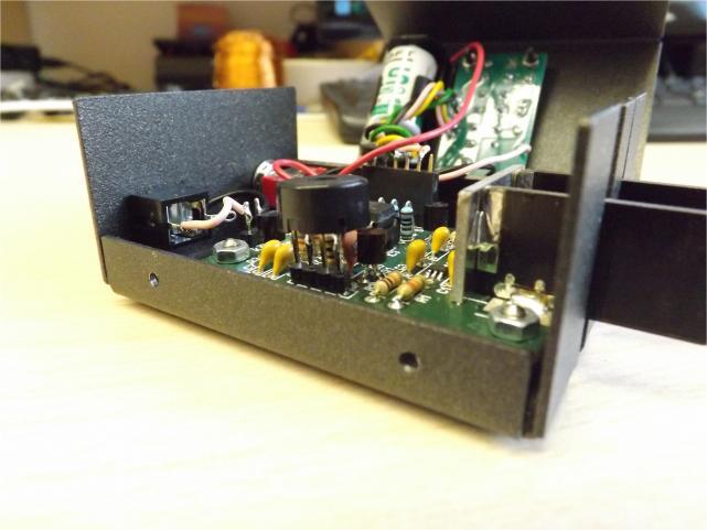
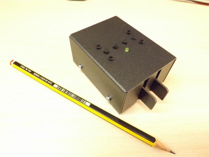
11 TKEY-K16 USE The basic use of the TKEY-K16 electronic keyer is very simple, however if you want to use all its functions you should read carefully the K16 user guide where you can see all the programming commands and functions in great detail. You can download it from here: ANNEXED. INSTALLATION IN THE BOX The installation of the TKEY-K16 in its box is a simple job. See the following images that give you an idea of how to make the wiring. 1.- The battery is glued with double-sided adhesive tape as shown in the images. The red (+) battery wire must go to the ON / OFF switch and the black wire (-) to the "GND" terminal of the "3-5V" input. 2.- The "K OUT" output will go to the output Jack connector. 3.- The led cable will go to the ON / OFF switch and the "3-5V" input. 4.- Solder the terminals wires "GND", "CMD", "M2", "M3", "M4" to the push-button panel. 5.- Solder the Piezo-speaker directly to the terminals "S" and "GND" 6.- For the fastening of the push-button board, 4 x M2 screws and nuts. TKEY-K16 Touch CW electronic keyer Page 11

12 TKEY-K16 Touch CW electronic keyer Page 12
13 LIMITED WARRANTY Please read carefully BEFORE building your kit All electronic components and hardware supplied with the kit are under warranty in case of any manufacturing defect for the period of one year after purchase. The warranty does not include the transmitter final amplifier transistor. The original purchaser has the option of examining the kit and manual for 10 days. If, within this period, the buyer decides not to build the kit, he/she may return the entire unassembled kit at their own expense for the shipping expenses. The shipping expenses and sales commissions (i.e. bank, Ebay, and Paypal commissions) included in the purchase price will not be returned. Please, BEFORE returning a product, request instructions by at: ea3gcy@gmail.com Javier Solans, EA3GCY, warrants this device to function according to the specifications, provided that it is assembled and adjusted as described in this documentation, and used correctly according to all provided instructions. It is your responsibility to follow all the instructions in the manual, to identify all the components correctly, and to use good workmanship and proper tools and instruments in the construction and adjustment of this kit. REMEMBER: This kit will not work as a commercially manufactured product; however, if can often give similar results. Do not expect great performance, BUT YOU ARE SURE TO HAVE LOTS OF FUN! If you believe that there is a missing component for the kit, please do a thorough inventory of all parts using the parts list in the manual. Check all bags, envelopes and boxes carefully. If needed, you may me and I will replace any component that you are missing. Even if you can find the exact part locally, please let me know so that we are aware of the problem to help other customers. I can also supply any part that you have lost, damaged or broken accidently. If you find any errors in this manual or would like to make a comment, please do not hesitate to contact me at: ea3gcy@gmail.com THANK YOU for building the TKEY-K16 kit. Enjoy QRP! 73 Javier Solans, EA3GCY TKEY-K16 Touch CW electronic keyer Page 13
14 SCHEMATIC TKEY-K16 Touch CW electronic keyer Page 14
DL-1A. RF dummy load - 50Ω 20W. Assembly manual. Last update: May 1, Thank you for constructing the DL-1A dummy load kit
 DL-1A RF dummy load - 50Ω 20W Assembly manual Last update: May 1, 2016 ea3gcy@gmail.com Updates and news at: www.qsl.net/ea3gcy Thank you for constructing the DL-1A dummy load kit Have fun assembling it
Introduction 1. Green status LED, controlled by output signal ST. Sounder, controlled by output signal Q6. Push switch on input D6
 Introduction 1 Welcome to the GENIE microcontroller system! The activity kit allows you to experiment with a wide variety of inputs and outputs... so why not try reading sensors, controlling lights or
Mini-Yack Iambic Keyer
 Mini-Yack Iambic Keyer Assembly Instructions Mini-Yack is a "bare bones" Iambic keyer for embedding into QRP and home brew equipment. The keyer has the following features: Keying from 1-50WPM YACK memory
Introduction 1. Digital inputs D6 and D7. Battery connects here (red wire to +V, black wire to 0V )
") Introduction 1 Welcome to the magical world of GENIE! The project board is ideal when you want to add intelligence to other design or electronics projects. Simply wire up your inputs and outputs and away
Introduction 1 Welcome to the magical world of GENIE! The project board is ideal when you want to add intelligence to other design or electronics projects. Simply wire up your inputs and outputs and away
Introduction 1. Green status LED, controlled by output signal ST
 Introduction 1 Welcome to the magical world of GENIE! The project board is ideal when you want to add intelligence to other design or electronics projects. Simply wire up your inputs and outputs and away
VU-1 VU Meter Kit Volume Unit Meter
 VU-1 VU Meter Kit Volume Unit Meter Simplicity Counts, Detail Matters. No part of this document may be reproduced, either mechanically or electronically, posted online on the Internet, in whole or in part,
Bill of Materials: Super Simple Water Level Control PART NO
 Super Simple Water Level Control PART NO. 2169109 Design a simple water controller in which electrodes are required to sense high and low water levels in a tank. Whenever the water level falls below the
Total solder points: 123 Difficulty level: beginner 1. advanced AUDIO ANALYZER K8098. audio gea Give your. . high-tech ILLUSTRATED ASSEMBLY MANUAL
 Total solder points: 123 Difficulty level: beginner 1 2 3 4 5 advanced AUDIO ANALYZER K8098 ra audio gea Give your. look high-tech ILLUSTRATED ASSEMBLY MANUAL H8098IP-1 Features & Specifications Features
Mal-2 assembly guide v1.0
 Mal-2 assembly guide v.0 SONIC POTIONS Schematic and BOM The BOM can be found on Google Docs Prepare the PCB Separate the PCBs using some pliers. PCB We start with the lower PCB and assemble it beginning
Installing The PK-AM keyer and. from Jackson Harbor Press Operating: A Morse code keyer chip with pot speed control
 Installing The PK-AM keyer and from Jackson Harbor Press Operating: A Morse code keyer chip with pot speed control The PK-AM keyer is a modification for the PK-AM kit, it changes the AM transmitter to
ADD AN AUDIO MESSAGE TO YOUR PRODUCT WITH THIS RECORD & PLAYBACK KIT
 ADD AN AUDIO MESSAGE TO YOUR PRODUCT WITH THIS RECORD & PLAYBACK KIT BUILD INSTRUCTIONS Before you start take a look at the Printed Circuit Board (PCB). The components go in the side with the writing on
Main PCB (The small one)
") Thanks for choosing our kits! This manual is written taking with the problems that we usually find in our workshops in mind. Also the order is meant to make assembly as easy as possible. Some steps are
Thanks for choosing our kits! This manual is written taking with the problems that we usually find in our workshops in mind. Also the order is meant to make assembly as easy as possible. Some steps are
Build A Video Switcher
 Build A Video Switcher VIDEOSISTEMAS serviciotecnico@videosistemas.com www.videosistemas.com Reprinted with permission from Electronics Now Magazine September 1997 issue Copyright Gernsback Publications,
MONO AMPLIFIER KIT ESSENTIAL INFORMATION. Version 2.2 CREATE YOUR OWN SPEAKER DOCK WITH THIS
 ESSENTIAL INFORMATION BUILD INSTRUCTIONS CHECKING YOUR PCB & FAULT-FINDING MECHANICAL DETAILS HOW THE KIT WORKS CREATE YOUR OWN SPEAKER DOCK WITH THIS MONO AMPLIFIER KIT Version 2.2 Build Instructions
Parts Checklist - Please note there is no resistor R3. Diodes, LED and transistors are polarized see construction stages
 Xtal Check Kit build Read me first! -------- UPDATED GUIDE------ September 12, 2018--------- The following steps are designed to get your Xtal check kit built and operational. This is a good beginner s
TECHNOLOGY WILL SAVE US: THE LUMIPHONE
 TECHNOLOGY WILL SAVE US: THE LUMIPHONE This is a step-by-step guide to soldering your own Lumiphone. The equipment you should have at your station: goggles, soldering mat, soldering Iron, solder and side
VEC-201K Owner's Manual CW Keyer Kit CW - Keyer VEC-201
 CW - Keyer VEC-20 IMPORTANT WARRANTY INFORMATION! PLEASE READ Return Policy on Kits When Not Purchased Directly From Vectronics: Before continuing any further with your VEC kit check with your Dealer about
Atari PICO Composite Mod Board Installation Instructions:
 Atari PICO Composite Mod Board Installation Instructions: Installation Guide 6 Switch Atari 2600 6 Switch Video Mod Installation Guide Disclaimer: I am not responsible for any damage done to your Atari.
Multi-Key v2.4 Multi-Function Amplifier Keying Interface
 Multi-Key v2.4 Multi-Function Amplifier Keying Interface ASSEMBLY & OPERATION INSTRUCTIONS INTRODUCTION The Harbach Electronics, LLC Multi-Key is a multi-function external device designed for the safe
MAIN PCB (The small one) OPEN MAIN BOARD BAG A
 OPEN MAIN BOARD BAG A") THANKS FOR CHOOSING ONE OF OUR KITS! This manual has been written taking into account the common issues that we often find people experience in our workshops. The order in which the components are placed
THANKS FOR CHOOSING ONE OF OUR KITS! This manual has been written taking into account the common issues that we often find people experience in our workshops. The order in which the components are placed
DIY KIT MHZ 8-DIGIT FREQUENCY METER
 This kit is a stand-alone frequency meter capable of measuring repetitive signals up to a frequency of 50MHz. It has two frequency ranges (15 and 50 MHz) as well as two sampling rates (0.1 and 1 second).
Hamcrafters K44 CW Keyboard/Reader Kit Assembly Guide Revision A.0
 Introduction Figure 1 Assembled K44 This document will describe how to assemble and test a K44 Kit. The assembly requires reasonably good soldering skill. Before you start working, gather the following
DIY Guide - Building Franky v1.1, the SEGA Audio and Videocard for MSX
 DIY Guide - Building Franky v1.1, the SEGA Audio and Videocard for MSX 2015 FRS & MSXpró. Translation by FRS and Supersoniqs. Table of Contents Introduction... 3 Materials needed... 3 Audio volume boost...
While the parts are already inventoried at the factory, please verify the inventory check as you go:
 Thank you for purchasing the kit for building the WJ9J DTMF controller. After building, you should read the document on operation (WJ9JDTMFControllerV5.pdf) in order to use. This is also in the link in
NewScope-7A Operating Manual
 2016 SIMMCONN Labs, LLC All rights reserved NewScope-7A Operating Manual Preliminary May 13, 2017 NewScope-7A Operating Manual 1 Introduction... 3 1.1 Kit compatibility... 3 2 Initial Inspection... 3 3
AT-AUTO (tm) QRO Keyline Upgrade Kit Installation Manual
 QRO Keyline Upgrade Kit Installation Manual") AT-AUTO (tm) QRO Keyline Upgrade Kit Installation Manual P.O. Box 341543 Beavercreek, Ohio 45434 5 September, 2015 Copyright 2015 ii Contents 1 Introduction 2 1.1 General Description and Purpose........................
AT-AUTO (tm) QRO Keyline Upgrade Kit Installation Manual P.O. Box 341543 Beavercreek, Ohio 45434 5 September, 2015 Copyright 2015 ii Contents 1 Introduction 2 1.1 General Description and Purpose........................
Documentation VFD clock 8 a clock
 Documentation VFD clock 8 a clock This documentation is protected by our copyright. It must not be used for commercial purposes. Congratulations on your purchase of your VFD clock. To guarantee success
Tube Cricket Build Guide
 Tube Cricket Build Guide The Tube Cricket is a small-wattage amp that puts out about 1 watt of audio power. With a 12AU7 tube-preamp and a JRC386 power amp, the Tube Cricket gives you great tone in a compact
8 PIN PIC PROGRAMMABLE BOARD (DEVELOPMENT BOARD & PROJECT BOARD)
") ESSENTIAL INFORMATION BUILD INSTRUCTIONS CHECKING YOUR PCB & FAULT-FINDING MECHANICAL DETAILS HOW THE KIT WORKS LEARN ABOUT PROGRAMMING WITH THIS 8 PIN PIC PROGRAMMABLE BOARD (DEVELOPMENT BOARD & PROJECT
ESSENTIAL INFORMATION BUILD INSTRUCTIONS CHECKING YOUR PCB & FAULT-FINDING MECHANICAL DETAILS HOW THE KIT WORKS LEARN ABOUT PROGRAMMING WITH THIS 8 PIN PIC PROGRAMMABLE BOARD (DEVELOPMENT BOARD & PROJECT
Constructing and Operating: The Island Keyer
 Constructing and Operating: The Island Keyer Construction: General notes about building: The components should be inserted a few at a time, soldered in place and then the leads are clipped. Note that all
QUIZ BUZZER KIT TEACHING RESOURCES. Version 2.0 WHO ANSWERED FIRST? FIND OUT WITH THIS
 TEACHING RESOURCES SCHEMES OF WORK DEVELOPING A SPECIFICATION COMPONENT FACTSHEETS HOW TO SOLDER GUIDE WHO ANSWERED FIRST? FIND OUT WITH THIS QUIZ BUZZER KIT Version 2.0 Index of Sheets TEACHING RESOURCES
The NorCal SMT Dummy Load Assembly and Operating Manual Rev. 1.0 January 4, 2005
 The NorCal SMT Dummy Load Assembly and Operating Manual Rev. 1.0 January 4, 2005 Copyright 2005 W3CD 1 1. Introduction The NorCal SMT Dummy Load is a practice kit for anyone wishing to gain some experience
Fixed Audio Output for the K2 Don Wilhelm (W3FPR) & Tom Hammond (NØSS) v August 2009
 & Tom Hammond (NØSS) v August 2009") Fixed Audio Output for the K2 Don Wilhelm (W3FPR) & Tom Hammond (NØSS) v. 2.1 06 August 2009 I have had several requests to provide a fixed audio output from the K2. After looking at the circuits that
Fixed Audio Output for the K2 Don Wilhelm (W3FPR) & Tom Hammond (NØSS) v. 2.1 06 August 2009 I have had several requests to provide a fixed audio output from the K2. After looking at the circuits that
TATTLE-TALE TELEPHONE RECORDER KIT
 TATTLE-TALE TELEPHONE RECORDER KIT Ramsey Electronics Model No. TT1C Ever want to tape that annoying or obscene phone call? Want to find out who is making those long distance calls from your phone? Or
ELECTRONIC GAME KIT TEACHING RESOURCES. Version 2.0 BUILD YOUR OWN MEMORY & REACTIONS
 TEACHING RESOURCES SCHEMES OF WORK DEVELOPING A SPECIFICATION COMPONENT FACTSHEETS HOW TO SOLDER GUIDE BUILD YOUR OWN MEMORY & REACTIONS ELECTRONIC GAME KIT Version 2.0 Index of Sheets TEACHING RESOURCES
ELECTRONIC GAME KIT ESSENTIAL INFORMATION. Version 2.0 BUILD YOUR OWN MEMORY & REACTIONS
 ESSENTIAL INFORMATION BUILD INSTRUCTIONS CHECKING YOUR PCB & FAULT-FINDING MECHANICAL DETAILS HOW THE KIT WORKS BUILD YOUR OWN MEMORY & REACTIONS ELECTRONIC GAME KIT Version 2.0 Build Instructions Before
COLOUR CHANGING USB LAMP KIT
 TEACHING RESOURCES SCHEMES OF WORK DEVELOPING A SPECIFICATION COMPONENT FACTSHEETS HOW TO SOLDER GUIDE SEE AMAZING LIGHTING EFFECTS WITH THIS COLOUR CHANGING USB LAMP KIT Version 2.1 Index of Sheets TEACHING
GUIDE TO ASSEMBLY OF ERICA SYNTHS DELAY MODULE
 If you are reading this, most probably, you are about to build Erica Synths DIY DELAY module. The module is 4mm deep, skiff friendly, has solid mechanical construction and doesn t require wiring. Erica
Industrial Monitor Update Kit
 Industrial Monitor Update Kit (Bulletin Number 6157) Installation Instructions 2 Table of Contents Table of Contents Industrial Monitor Update Kit... 3 Overview... 3 Part 1 - Initial Preparation... 5 Part
Assembly Instructions And User Guide. Nixie FunKlock. FunKlock Issue 4 (1 February 2017)
") Assembly Instructions And User Guide Nixie FunKlock - 1 - Issue Number Date REVISION HISTORY 4 1 February 2017 New diode for D2 3 27 December 2013 C7 / C8 error page 15 2 7 November 2013 Errors corrected
Assembly Instructions And User Guide Nixie FunKlock - 1 - Issue Number Date REVISION HISTORY 4 1 February 2017 New diode for D2 3 27 December 2013 C7 / C8 error page 15 2 7 November 2013 Errors corrected
RECORD & PLAYBACK KIT
 TEACHING RESOURCES SCHEMES OF WORK DEVELOPING A SPECIFICATION COMPONENT FACTSHEETS HOW TO SOLDER GUIDE ADD AN AUDIO MESSAGE TO YOUR PRODUCT WITH THIS RECORD & PLAYBACK KIT Version 2.1 Index of Sheets TEACHING
7 SEGMENT LED DISPLAY KIT
 ESSENTIAL INFORMATION BUILD INSTRUCTIONS CHECKING YOUR PCB & FAULT-FINDING MECHANICAL DETAILS HOW THE KIT WORKS CREATE YOUR OWN SCORE BOARD WITH THIS 7 SEGMENT LED DISPLAY KIT Version 2.0 Which pages of
Nixie Tube Clock Type Marsden
 Assembly Instructions And User Guide Nixie Tube Clock Type Marsden Software version: RTC-1.3 PCB Revision: 16 Aug 10-1 - 1. INTRODUCTION 1.1 About the clock Nixie clock type Marsden is a compact design
ILER-DDS. for ILER & EGV kits Assembly manual. Last review: October 01, 2014 Translated by Jon EA2SN
 ILER-DDS for ILER & EGV kits Assembly manual Last review: October 01, 2014 Translated by Jon EA2SN ea3gcy@gmail.com Latest updates and news: www.qsl.net/ea3gcy Thanks for purchasing the ILER-DDS VFO kit.
Nixie Clock Type Frank 2 Z570M
 Assembly Instructions And User Guide Nixie Clock Type Frank 2 Z570M Software version: 7R PCB Revision: 11 April 09-1 - 1. INTRODUCTION 1.1 About the clock Nixie clock type Frank 2 is a compact design with
Operatinq Instructions
 Introduction Welcome to the world of effortless CW. With the MFJ-403 you will have a professional sounding fist in no time! Whether you are a Novice or seasoned Extra, the MFJ-403 has the features you
The Morse Code Trainer Reaching the pinnacle of CW Operations!
 The Morse Code Trainer Reaching the pinnacle of CW Operations! Finally an all in one tool for learning and increasing Morse code operations. The Morse Code Trainer enhances the learning experience by immersing
SN-Class Nixie Clock Kits
 Assembly Instructions And User Guide SN-Class Nixie Clock Kits - 1 - REVISION HISTORY Issue Date Reason for Issue Number 1 20 November 2017 New document - 2 - 1. INTRODUCTION 1.1 About the How can the
[ Photos ] [ Wares ] [ Library ] [ Dave's Web ] [ Matt's Web ] Wares [ SWISH ] [ Simple Search ] [ Trunk Calc ]
![[ Photos ] [ Wares ] [ Library ] [ Dave's Web ] [ Matt's Web ] Wares [ SWISH ] [ Simple Search ] [ Trunk Calc ]](/thumbs/85/91698811.jpg "[ Photos ] [ Wares ] [ Library ] [ Dave's Web ] [ Matt's Web ] Wares [ SWISH ] [ Simple Search ] [ Trunk Calc ]") [ Photos ] [ Wares ] [ Library ] [ Dave's Web ] [ Matt's Web ] Wares [ SWISH ] [ Simple Search ] [ Trunk Calc ] Realistic PRO-2006 Hardware Modifications Note Edited on January 1st, 1970, 00:00 UT. Improper
[ Photos ] [ Wares ] [ Library ] [ Dave's Web ] [ Matt's Web ] Wares [ SWISH ] [ Simple Search ] [ Trunk Calc ] Realistic PRO-2006 Hardware Modifications Note Edited on January 1st, 1970, 00:00 UT. Improper
DSO138mini Troubleshooting Guide
 DSO138mini Troubleshooting Guide Applicable main board: 109-13800-00I Applicable analog board: 109-13801-00H 1. Frequently Found Problems 1) LCD completely dark. No backlight 2) LCD lights up but no display
DEM 9ULNACK 3.4 GHz. PHEMT LNA amplifier complete kit assembly guide
 DEM 9ULNACK 3.4 GHz. PHEMT LNA amplifier complete kit assembly guide SPECIFICATIONS Noise Figure: < 0.8 db Gain: > 15 db Frequency Range: 3400-3500 MHz Input Voltage: 7-16 VDC Description: The 9ULNACK
Nixie Clock Type Frank 3
 Assembly Instructions And User Guide Nixie Clock Type Frank 3 Software version: 7R PCB Version: 11 April 09-1 - 1. INTRODUCTION 1.1 About the clock Nixie clock type Frank 3 is a compact design with all
COMPONENT PREPARATION AND MANUAL INSERTION TRAINING CERTIFICATION TEST (DVD-44C) v.2
 v.2") This test consists of fifteen multiple-choice questions. All questions are from the video: Component Preparation and Manual Insertion (DVD-44C). Each question has only one most correct answer. Circle the
This test consists of fifteen multiple-choice questions. All questions are from the video: Component Preparation and Manual Insertion (DVD-44C). Each question has only one most correct answer. Circle the
Christmas LED Snowflake Project
 Christmas LED Snowflake Project Version 1.1 (01/12/2008) The snowflake is a follow-on from my Christmas star project from a few years ago. This year I decided to make a display using only white LEDs, shaped
Galilean Moons. dual amplitude transmutator. DIY ASSEMBLY MANUAL v1.02
 Galilean Moons dual amplitude transmutator DIY ASSEMBLY MANUAL v1.02 Contents Contents... 2 Introduction... 3 Eurorack Kit Assembly... 4 Resistors... 4 IC Sockets... 5 Ceramic/Film Capacitors... 5 Transistors
PR-101 STEREO PREAMPLIFIER Phono Preamp ASSEMBLY MANUAL
 PR-101 STEREO PREAMPLIFIER Phono Preamp ASSEMBLY MANUAL 2016 AkitikA LLC All rights reserved Revision 1p18 March 12, 2016 Page 1 of 24 Table of Contents Table of Contents... 2 Table of Figures... 2 Section
Total solder points: 117 Difficulty level: beginner advanced. RGB Controller K8088 ILLUSTRATED ASSEMBLY MANUAL
 Total solder points: 117 Difficulty level: beginner 1 2 3 4 5 advanced RGB Controller K8088 Control incandescent bulbs, LEDs, common anode led strips, etc... ILLUSTRATED ASSEMBLY MANUAL H8088IP-1 Features
Bill of Materials: 7-Segment LED Die with Arduino PART NO
 7-Segment LED Die with Arduino PART NO. 2190194 This project is based on the Arduino environment so that you can manipulate a die with a simple common anode 7-segment LED, a transistor PNP-2N3906, 10 resistors
H2633IP-1 RELAY CARD K2633
 H2633IP-1 RELAY CARD K2633 Control up to 4 high-power circuits from a low-power drive circuit. Features & Specifications The connection of a few relays to the outputs of an electronic circuit might be
Azatrax Model Railroad Track Signal Control - Single Track
 Installation Guide Azatrax Model Railroad Track Signal Control - Single Track TS2 What it is: The TS2 operates one or two trackside block signals (one in each direction) on one track to simulate the block
ANTUMBRA FADE MANUAL
 ANTUMBRA FADE MANUAL TABLE OF CONTENTS 01. INSTALLATION 4 02. BACK 5 03. FRONT 6 04. USE 7 05. LINK 8 06. BILL OF MATERIALS 9 07. BUILD NOTES 10 08. BACK 11 09. FRONT 14 10. MODIFICATION 15 11. FINISHED
Ten-Tec (865) Service Department:(865)
 Service Department:(865)") Ten-Tec (865) 453-7172 Service Department:(865) 428-0364 Installation Instructions for Ten-Tec Jupiter AT538K Tuner Kit The installation of the AT538K is divided into two steps. The first step is to reprogram
Ten-Tec (865) 453-7172 Service Department:(865) 428-0364 Installation Instructions for Ten-Tec Jupiter AT538K Tuner Kit The installation of the AT538K is divided into two steps. The first step is to reprogram
MAKE AN RGB CONTROL KNOB.
 MAKE AN RGB CONTROL KNOB. This is a knob based colour changing controller that uses a custom programmed microcontroller to pack a lot of features into a small affordable kit. The module can drive up to
These are the illustrated step-by-step guidelines for upgrading your Quad 34 with the Dada Electronics upgrade-kit.
 Quad 34 DIY illustrated guidelines version 2.12 These are the illustrated step-by-step guidelines for upgrading your Quad 34 with the Dada Electronics upgrade-kit. The Quad 34 is a very good preamplifier,
SEP Bright Pi v1.0 Assembly Instructions
 SEP Bright Pi v1.0 Assembly Instructions When you purchased your Bright Pi v1.0 kit, you should have received an anti-static bag with some components in it which will require soldering together in order
Build Your Own Clone Super 8 Kit Instructions
 Build Your Own Clone Super 8 Kit Instructions Warranty: BYOC, Inc. guarantees that your kit will be complete and that all parts and components will arrive as described, functioning and free of defect.
Bill of Materials: Magic Color PART NO
 Magic Color PART NO. 2193838 Magic color is a guessing game. With this game you can surprise your friends and leave them with amazement, how the game guesses what they have in their minds. Only two selections
STROBOSCOPE LIGHT EFFECT KIT
 STROBOSCOPE LIGHT EFFECT KIT Easy to build stroboscope for general applications Flash frequency: 5 to 15 flashes per second Power supply: 110VAC Power consumption: 13W max. PCB dimensions: 50 x 75mm modifications
Obtained from Omarshauntedtrail.com
 http://www.cindybob.com/halloween/ledlighting/ledspotlights/ Introduction In our 2005 haunt providing 120V AC power to the various lights and props requiring it became a fairly large problem. Extension
Analog Style LED Clock
 Analog Style LED Clock Operation and Assembly Manual For use with PCB Rev 2.1 Copyright 2018 All Rights Reserved. Manual version 2.1c, for use with PCB revision 2.1, Software version 2.0.0. The electronic
UAV Ultimate Atari Video A7800
 UAV Ultimate Atari Video A7800 Basic Install guide because this is really easy mod to do! The UAV is a wonderful piece of tech for what it can do. To summarize, the UAV is a replacement video encoder and
N3ZI Digital Dial Manual For kit with Serial LCD Rev 3.04 Aug 2012
 N3ZI Digital Dial Manual For kit with Serial LCD Rev 3.04 Aug 2012 Kit properly assembled and configured for Standard Serial LCD (LCD Not yet connected) Kit Components Item Qty Designator Part Color/Marking
Elecraft KXAT2 Automatic Antenna Tuner Installation Instructions
 Elecraft KXAT2 Automatic Antenna Tuner Installation Instructions Revision A, May 23, 2016 E740294 Copyright 2016, Elecraft, Inc. All Rights Reserved Introduction The KXAT2 internal automatic antenna tuner
MUK REAR PANEL ASSEMBLY ASSEMBLY INSTRUCTIONS
 Rev B. 13 August 2017 ASSEMBLY INSTRUCTIONS The Midnight Ultimate Keyer (MUK) consists of two functional assemblies: Rear Panel containing the interface and power connectors. Front Panel containing the
MOD028 GLOCKENSPIEL TECHNO-MUSIC-OLOGY
 MOD028 GLOCKENSPIEL TECHNO-MUSIC-OLOGY MOD028 - Techno-music-ology Kit Contents Motor Controller PCBs 14 220R (red red brown gold) resistors 2 330R (orange orange brown gold) resistors 16 1N4001 diodes
Etherwave Plus Field Upgrade Instructions
 Etherwave Plus Field Upgrade Instructions The Etherwave Plus Field Upgrade is an advanced project for upgrading a standard Moog Music Etherwave theremin to the Etherwave Plus. The new features of the Etherwave
TR-Plus T/R Switch Assembly and Operation Manual. Introduction
 TR-Plus T/R Switch Assembly and Operation Manual Revised: 7 February 2015 2015 Tucson Amateur Packet Radio Corporation Introduction The TAPR TR-Plus is a transmit/receive ( T/R ) switch that connects a
Frequency counter / Digital Dial
 Frequency counter / Digital Dial The Digital Dial is primarily intended to be used as a simple means of adding a digital frequency read out to single band QRP radios. A programmable IF offset feature allows
VU Meter Buffer DIY Kit
 VU Meter Buffer DIY Kit Warning This document is distributed for educational purposes only. This equipment operates at potentially lethal voltages. Only trained, qualified personnel should operate, maintain,
N3ZI Digital Dial Manual For kit with Backlit LCD Rev 4.00 Jan 2013 PCB
 N3ZI Digital Dial Manual For kit with Backlit LCD Rev 4.00 Jan 2013 PCB Kit Components Item Qty Designator Part Color/Marking PCB 1 LCD Display 1 LCD 1602 Volt Regulator 1 U1 78L05, Black TO-92 Prescaler
Hardware installation
 Hardware installation 5. Place and fix the OMT to the interface without tightening the screws. Figure 291: Place and fix the OMT to the interface Note: Take care to place the OMT with the engraved ARROW
FSM User Guide Page 1 of 28
 FSM User Guide Page 1 of 28 Field Strength Meter User Guide and Kit Assembly Instructions PCB V1.1 Important: Always use or print this document in colour as there are references to the colours of components.
Australian Technical Production Services
 Australian Technical Production Services Dual Rail Crowbar Copyright notice. These notes, the design, schematics and diagrams are Copyright Richard Freeman, 2015 While I am happy for the notes to be printed
Color Organ Triple Deluxe II.
 http://wwwinstructablescom/id/color-organ-triple-deluxe-ii/ Food Living Outside Play Technology Workshop Color Organ Triple Deluxe II by ledartist on January 13, 2013 Table of Contents Color Organ Triple
Nixie Clock Kit IN-12B color LED backlit Operation Manual Nixie Clock Kit IN-12B V6.0 ( All Right Reserved 2015 )
") Nixie Clock Kit IN-B color LED backlit Operation Manual Nixie Clock Kit IN-B V. ( All Right Reserved ) - - Operation Manual IN-B Nixie Clock Power for your Nixie Clock The clock does not include a wall
Nixie Clock Kit IN-B color LED backlit Operation Manual Nixie Clock Kit IN-B V. ( All Right Reserved ) - - Operation Manual IN-B Nixie Clock Power for your Nixie Clock The clock does not include a wall
CMD197C GHz Distributed Driver Amplifier
 Features Functional Block Diagram Wide bandwidth High linearity Single positive supply voltage On chip bias choke Pb-free RoHs compliant 4x4 mm SMT package Description The CMD197C4 is a wideband GaAs MMIC
Blinky Eyes Animated Display
 Blinky Eyes Animated Display Ramsey Electronics Model No. BE66 A super eye-catching display that is sure to attract attention. Microcontroller selects from different animations for startling or scary displays.
Bas Gialopsos Atari PureVideo Encoder Module 2600VECr5.2
 Bas Gialopsos 2014 Atari PureVideo Encoder Module 2600VECr5.2 Table of Contents Description Disclaimer Technical and Signal Identification Installation Instructions Tools Required Caution Installation
DDS VFO CONSTRUCTION MANUAL. DDS VFO Construction Manual Issue 1.1 Page 1
 DDS VFO CONSTRUCTION MANUAL DDS VFO Construction Manual Issue 1.1 Page 1 Important Please read before starting assembly STATIC PRECAUTION The DDS VFO kit contains the following components which can be
"Sophisticated Model Railroad Electronics"
 LOGIC RAIL TM "Sophisticated Model Railroad Electronics" TECHNOLOGIES 21175 Tomball Pkwy Phone: (281) 251-5813 Suite 287 email: info@logicrailtech.com Houston, TX 77070 http://www.logicrailtech.com Block
On-screen display signal strength meter Version 1.02
 OSD-SSM On-screen display signal strength meter Version 1.02 Copyright 2000 Intuitive Circuits, LLC D escription OSD-SSM is an on-screen display overlay board with analog to digital circuitry which continuously
Dust Sensor using GP Y
 Dust Sensor using GP Y Dust sensors detect fine dust ( aerosol ) floating in the air. They are used to determine air quality indoor and outdoor. Limits of the GP2Y10 The GP2Y10 sensor was developed to
Nixie Clock Kit V1.08 Assembly and Operation
 Nixie Clock Kit V1.08 Assembly and Operation Hardware Revision 14.05.2005 Software Version 6.0 Revision 19.04.2006 This document is copyrighted. No parts of this documentation may be used commercially.
Building the BX24-AHT
 Building the BX24-AHT file:///f /LASER/build-it.htm (1 of 8) [03/04/2002 5:21:52 PM] file:///f /LASER/build-it.htm (2 of 8) [03/04/2002 5:21:52 PM] Tips & Tricks Use a 25W or smaller soldering iron with
CUBE 2001 WORLD S SMALLEST HIGH POWER TV TRANSMITTER KIT
 CUBE 2001 WORLD S SMALLEST HIGH POWER TV TRANSMITTER KIT Ramsey Electronics Model No. C2001 Transmits perfect video - and you can hide it under a quarter! Fully assembled, just add a camera and battery
Building a MidiBox LCD Cable
 Building a MidiBox LCD Cable By Jim Henry, 3-Apr-2004 An LCD panel may be connected to the Core module by a 16 conductor flat ribbon cable. A 16 pin insulation displacement connector (IDC) terminates one
Nixie Clock Type SixNix
 Assembly Instructions And User Guide Nixie Clock Type SixNix - 1 - Issue Number Date REVISION HISTORY Reason for Issue 6 20 March 2014 Removed WWVB Support 5 14 July 2012 New Board Issue - 19 July 12 4
Lab 7: Soldering - Traffic Light Controller ReadMeFirst
 Lab 7: Soldering - Traffic Light Controller ReadMeFirst Lab Summary The two-way traffic light controller provides you with a quick project to learn basic soldering skills. Grading for the project has been
Pixie Construction Notes
 Pixie Construction Notes PCB V2a February 4 th 2015 Please note that this document is still currently under revision and we apologise for any errors or omissions. Readers should feel free to e-mail any
Service Call: Fiber Optic Installation and Repair
 Service Call: Fiber Optic Installation and Repair Tools Required: Tools available from www.bohlinger.biz Cable: Terex P/N 453830 Stripper Block: P/N 65-020-01 Termination Block: P/N 65-020-02 Utility Knife