EECS 151/251A Spring 2018 Digital Design and Integrated Circuits Instructors: N. Weaver & J. Wawrzynek. Lecture 2 EE141
|
|
|
- Gyles Webb
- 5 years ago
- Views:
Transcription
1 EECS 151/251A Spring 2018 Digital Design and Integrated Circuits Instructors: N. Weaver & J. Wawrzynek Lecture 2
2 Class Schedule - UPDATE Discussions: Friday 11am-12, 106 Moffit Library LAB A (ASIC): W 5-8pm (125 Cory) - Taehwan LAB B (FPGA): W 2-5pm (125 Cory) - Arya Th 2-5pm (125 Cory) - Arya Office Hours: Nick : Mo 1-3pm Soda John : Tu, Th 2:30pm-3:30pm Soda Taehwan: TBD Arya: TBD Homework out today, due: next Friday at 11:59PM 2
3 Schedule for this week First discussion this Friday Labs starting this week 3
4 Outline Methodology Basics Digital Logic Basic Concepts Early Design Design Implementation Alternatives Design Flows ASICs FPGAs 4
5 Methodology Basics
6 Basic Design Tradeoffs Improve on one at the expense of the others Tradeoffs exist at every level in the system design Design Specification Functional Description Performance, cost, power constraints Designer must make the tradeoffs needed to achieve the function within the constraints 6
7 Design Space & Optimality Pareto Optimal Frontier Performance (tasks/sec) high-performance at high-cost low-performance at low-cost Cost (# of components) 7

8 Design Methodologies Top-Down Design Starts at the top (root) and works down by successive refinement. Bottom-up Design Starts at the leaves & puts pieces together to build up the design. Which is better? In practice both are needed & used Top-down to handle the complexity (divide and conquer) Bottom-up since structure influenced by available primitives (in a well designed system) 8
9 Digital Logic Basic Concepts
 32 KByte Instruction and Data L1 caches Dual")

10 Digital Integrated Circuit Example (Old) PowerPC microprocessor microphotograph Superscalar (3 instructions/cycle) 6 execution units (2 integer and 1 double precision IEEE floating point) 32 KByte Instruction and Data L1 caches Dual Memory Management Units (MMU) External L2 Cache interface with integrated controller and cache tags. Comprises only transistors and wires. Connections to outside world (ex. motherboard) Memory interface Power (Vdd, GND) Clock input 10
11 Clock Signal Τ represents the time of one clock cycle. A source of regularly occurring pulses used to measure the passage of time. Waveform diagram shows evolution of signal value (in voltage) over time. Usually comes from an off-chip crystal-controlled oscillator. One main clock per chip/system. Distributed throughout the chip/system. Heartbeat of the system. Controls the rate of computation by directly controlling all data transfers. 11
12 Data Signals Random adder circuit at a random point in time: Observations: Most of the time, signals are in either low- or high-voltage position. When the signals are at the highor low-voltage positions, they are not all the way to the voltage extremes (or they are past). Changes in the signals correspond to changes in clock signal (but don t change every cycle). The facts: 1. Low-voltage represents binary 0 and high-voltage, binary Circuits are designed and built to be tolerant of noise and restoring. Deviations from ideal voltages are ignored. Outputs close to ideal. 3. In synchronous systems, all changes follow clock edges. 12
13 Circuit Delay Digital circuits cannot produce outputs instantaneously. In general, the delay through a circuit is called the propagation delay. It measures the time from when inputs arrive until the outputs change. The delay amount is a function of many things. Some out of the control of the circuit designer: Processing technology, the particular input values. And others under her control: Circuit structure, physical layout parameters. 13
14 Combinational Logic Blocks Example four-input function: Output a function only of the current inputs (no history). Truth-table representation of function. Output is explicitly specified for each input combination. In general, CL blocks have more than one output signal, in which case, the truth-table will have multiple output columns. a b c d y F(0,0,0,0) F(0,0,0,1) F(0,0,1,0) F(0,0,1,1) F(0,1,0,0) F(0,1,0,1) F(0,1,1,0) F(0,1,1,1) F(1,0,0,0) F(1,0,0,1) F(1,0,1,0) F(1,0,1,1) F(1,1,0,0) F(1,1,0,1) F(1,1,1,0) F(1,1,1,1) Truth Table 14
15 Example CL Block 2-bit adder. Takes two 2-bit integers and produces 3-bit result. Think about truth table for 32-bit adder. It s possible to write out, but it might take a while! a1 a0 b1 b0 c2 c1 c Theorem: Any combinational logic function can be implemented as a networks of logic gates. 15
16 Logic Gates AND ab c ab c OR NOT a b NAND ab c NOR ab c XOR ab c Logic gates are often the primitive elements out of which combinational logic circuits are constructed. In some technologies, there is a one-to-one correspondence between logic gate representations and actual circuits (ASIC standard cells have gate implementations). Other times, we use them just as another abstraction layer (FPGAs have no real logic gates). How about these gates with more than 2 inputs? Do we need all these types? 16
17 Example Logic Circuit a b c y a b c y How do we know that these two representations are equivalent? Will come back to this later! 17


18 Logic Gate Implementation Logic circuits have been built out of many different technologies. If we have a basic logic gate (AND or OR) and inversion we can build a complete logic family. DTL Hydraulic CMOS Gate Mechanical LEGO logic gates. A clockwise rotation represents a binary one while a counter-clockwise rotation represents a binary zero. 18
19 Restoration/Regeneration A necessary property of any suitable technology for logic circuits is "Restoration or Regeneration Circuits need: to ignore noise and other non-idealities at the their inputs, and generate "cleaned-up" signals at their output. Otherwise, each stage propagates input noise to their output and eventually noise and other non-idealities would accumulate and signal content would be lost. 19
20 Inverter Example of Restoration Example (look at 1-input gate, to keep it simple): Idealize Inverter Actual Inverter VIN VOUT Inverter acts like a non-linear amplifier The non-linearity is critical to restoration Other logic gates act similarly with respect to input/output relationship. 20
21 State Elements: circuits that store info Examples: registers, memories Register: Under the control of the load signal, the register captures the input value and stores it indefinitely. load input register output often replace by clock signal (clk) n n The value stored by the register appears on the output (after a small delay). Until the next load, changes on the data input are ignored (unlike CL, where input changes change output). These get used for short term storage (ex: register file), and to help move coordinate data movement. 21

22 Register Transfer Level Abstraction (RTL) Any synchronous digital circuit can be represented with: Combinational Logic Blocks (CL), plus State Elements (registers or memories) State elements are mixed in with CL blocks to control the flow of data. clock Address Input Data Write Control Output Data Register file or Memory Block Sometimes used in large groups by themselves for long-term data storage. 22
23 Early Design
. These were IC processing companies.")
24 IC Design in the 70 s and early 80 s Circuit design, layout, and processing tightly linked. Logic design and layout was all done by-hand in an ad-hoc way Chip design was the domain of industry (Fairchild, Intel, Texas Instruments, ). These were IC processing companies. Those who controlled the physics controlled the creative agenda! Federico Faggin, Ted Hoff, Stan Mazor Introduced to help sell memory chips! The Intel 4004 microprocessor, which was introduced in The 4004 contained 2300 transistors and performed 60,000 calculations per second. Courtesy: Intel. 24
 the transparent covering.")
25 Early Design Practice Initially, designs were represented by hand drawings. Then masks where made by transferring drawings to rubylith. Base layer of heavy transparent dimensionally stable Mylar. A thin film of deep red cellophane-like material covers the base layer. Patterns formed by cutting (often by hand) the transparent covering. Later transition to an electronic format (CIF, GDS) meant: Layouts easily be stored and transmitted. Written to tape and transferred to manufacturer (tapeout).transmitted over the network (new idea back then). Software could automatically check for layout errors. Generated from a program - huge idea. 25

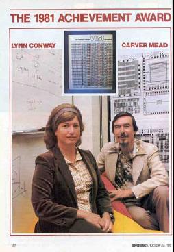
26 The start of the IC Design Revolution 26

. Sufficiently small set that designers could memorize.")
27 Geometric Design Rules Early on, to generate the mask information for fabrication, the designer needed intimate knowledge of the manufacturing process. Even once this knowledge was distilled to a set of Geometric Design Rules, this set of rules was voluminous with many special cases. Academics (C. Mead and others) came up with a much simplified set of design rules (single page description). A sort of API or abstraction of the process (back-end processing could automatically convert this information into masks). Sufficiently small set that designers could memorize. Sufficiently abstract to allow process engineers to shrink the process and preserve existing layouts. Process resolution becomes a parameter, λ. 27
 Simple standard geometric design rules where the key: these form the contract between the designer and manufacturer.")
28 Key Development: Silicon Foundries Separate the designer from the fabricator: Modeled after the printing industry. (Very few authors actually own and run printing presses!) Simple standard geometric design rules where the key: these form the contract between the designer and manufacturer. Designer sends the layout (in CIF format), foundry manufactures the chip and send back. Designer promises not to violate the design rules. Foundry promises to accurately follow layout. A scalable model for the industry: IC fab is expensive and complex. Amortizes the expense over many designers (batch processing with deep queues help). Designers and companies not held back by need to develop and maintain large expensive factories. fabless semiconductor companies - lots of these and very few foundries. TSMC, Global Foundries, UMC, Samsung, SMIC, 28
.")
.")
29 Computer Aided Design (1) Several advances lead to the development of interactive tools for generating layout: Computer based layout representation (CIF, GDS). Advances in computer graphics (thanks to Ivan Sutherland and friends) and display devices. Personal workstation (Xerox Alto - Chuck Thacker). Back room computers didn t have the necessary bandwidth to the display. Berkeley version - MAGIC 29
30 Early 80 s Design Methodology and Flow Schematic + Full- Custom Layout SPICE for timing, switch-level simulation for overall functionality, hand layout, no power analysis, layout verified with geometric Design Rule Checker (DRC) and later also Layout versus Schematic (LVS) Checkers Transistor Schematics SPICE Specification switch simulator layout vs. schematic hand layout CIF file geometric design rule checker 30
31 Computer Aided Design (2) For some time after CIF was invented: Layout was generated by hand, then typed in as a CIF file with a text editor. Layout compilers Soon some designers started embedding CIF primitives in conventional programming languages: LISP, pascal, fortran, C. This allows designers to write programs that generated layout. Such programs could be parameterized: define GENERATE_RAM(rows, columns) { for I from 1 to rows for J from 1 to columns (GENERATE_BITCELL)} GENERATE_RAM(128, 32); Lead to circuit/layout generation from higher level descriptions. Eventually, Cadence and Synopsys formed out of Berkeley. 31
32 Implementation Alternatives & Design Flow
33 Implementation Alternative Summary Full-custom: Standard-cell: Gate-array (structured ASIC): All circuits/transistors layouts optimized for application. Arrays of small function blocks (gates, FFs) automatically placed and routed. Partially prefabricated wafers customized with metal layers or vias. FPGA: Microprocessor: Domain Specific Processor: Wh Prefabricated chips customized with loadable latches or fuses. Instruction set interpreter customized through soft ware. Special instruction set interpreters (ex: DSP, NP, GPU). These days, ASIC almost always means Standard-cell. 33

34 The Important Distinction Instruction Binding Time When do we decide the functions (what operation is to be performed)? A. DeHon General Principles Earlier the decision is bound, the less area, delay/energy required for the implementation. Later the decision is bound, the more flexible the device. 34


35 Full-Custom Circuit styles and transistors are custom sized and drawn to optimize die, size, power, performance. High NRE (non-recurring engineering) costs Time-consuming and error prone layout Hand-optimizing the layout can result in small die for low per unit costs, extreme-lowpower, or extreme-high-performance. Common today for analog design. Requires full set of custom masks. High NRE usually restricts use to highvolume applications/markets or highlyconstrained and cost insensitive markets. 35

.")

36 Standard-Cell* Based around a set of pre-designed (and verified) cells Ex: NANDs, NORs, Flip-Flops, counters slices, buffers, Each cell comes complete with: layout (perhaps for different technology nodes and processes), Simulation, delay, & power models. Chip layout is automatic, reducing NREs (usually no hand-layout). Less optimal use of area and power, leading to higher per die costs than full-custom. Commonly used with other design implementation strategies (large blocks for memory, I/O blocks, etc.) 36
37 Gate Array Prefabricated wafers of active & gate layers & local interconnect, comprising, primarily, rows of transistors. Customize as needed with back-end metal processing (contact cuts, metal wires). Could use a different factory. CAD software understands how to make gates and registers. 37
 and higher per die costs.")
38 Gate Array Shifts large portion of design and mask NRE to vendor. Shorter design and processing times, reduced time to market for user. Highly structured layout with fixed size transistors leads to large sub-circuits (ex: Flip-flops) and higher per die costs. Memory arrays are particularly inefficient, so often prefabricated, also: Sea-of-gates, structured ASIC, master-slice. 38

39 Field Programmable Gate Arrays (FPGA) Two-dimensional array of simple logicand interconnectionblocks. Typical architecture: Look-up-tables (LUTs) implement any function of n-inputs (n=3 in this case). Optional connected Flip-flop with each LUT. Fuses, EPROM, or Static RAM cells are used to store the configuration. Here, it determines function implemented by LUT, selection of Flip-flop, and interconnection points. Many FPGAs include special circuits to accelerate adder carry-chain and many special cores: RAMs, MAC, Enet, PCI, SERDES, CPUs,... 39
40 FPGA versus ASIC total cost FPGAs cost effective ASICs cost effective volume FPGA ASIC ASIC: Higher NRE costs (10 s of $M). Relatively Low cost per die (10 s of $ or less). FPGAs: Low NRE costs. Relatively low silicon efficiency high cost per part (> 10 s of $ to 1000 s of $). Cross-over volume from cost effective FPGA design to ASIC was often in the 100K range. 40

 Synthesizable RTL model ( soft core, available in HDL) Their implementation hosted on a")
41 Microprocessors Where relatively low performance and/or high flexibility is needed, a viable implementation alternative: Software implements desired function Microcontroller, often with built in nonvolatile program memory and used as single function. Furthermore, instruction set processors are an abstraction level. Two ways: Instruction Set Architecture (ISA) Synthesizable RTL model ( soft core, available in HDL) Their implementation hosted on a variety of implementation platforms: standard-cell, gate-array, FPGA, other processors? 41
 permit easy integration of many blocks.")

42 System-on-chip (SOC) Brings together: standard cell blocks, custom analog blocks, processor cores, memory blocks, embedded FPGAs, Standardized on-chip buses (or hierarchical interconnect) permit easy integration of many blocks. Ex: AXI, AMBA, Sonics, IP Block business model: Hard- or softcores available from third party designers. ARM, inc. is the shining example. Hardand synthesizable RISC processors. ARM and other companies provide, Ethernet, USB controllers, analog functions, memory blocks, Qualcomm Snapdragon Pre-verified block designs, standard bus interfaces (or adapters) ease integration - lower NREs, shorten TTM. 42
43 Modern ASIC Methodology and Flow RTL Synthesis Based HDL specifies design as combinational logic + state elements Logic Synthesis converts hardware description to gate and flip-flop implementation Cell instantiations needed for blocks not inferred by synthesis (typically RAM) Event simulation verifies RTL Formal verification compares logical structure of gate netlist to RTL Place & route generates layout Timing and power checked statically Layout verified with LVS and GDRC RTL (Verilog/VHDL) + cell instantiations formal verification logic synthesis cell place & route GDSII Specification event simulator gate netlist (with area/perf/pwr estimates) GDRC, LVS, other checks timing/ power analysis 43
44 FPGAs
45 FPGA: Xilinx Virtex-5 XC5VLX110T Virtex-5 die photo A die is an unpackaged part


")

46 From die to PC board... Ball Grid rray (BGA) Flip-Chip Package 46

47 FPGA Overview Basic idea: two-dimensional array of logic blocks and flip-flops with a means for the user to configure (program): 1. the interconnection between the logic blocks, 2. the function of each block. Simplified version of FPGA internal architecture 47
48 Why are FPGAs Interesting? Technical viewpoint: For hardware/system-designers, like ASICs - only better: Tape-out new design every few minutes/hours. reconfigurability or reprogrammability may offer other advantages over fixed logic? In-field reprogramming? Dynamic reconfiguration? Self-modifying hardware, evolvable hardware? 48
49 Why are FPGAs Interesting? Staggering logic capacity growth (10000x): Year Introduced Device Logic Cells logic gate equivalents 1985 XC XC7V2000T 1,954,560 15,636,480 FPGAs have tracked Moore s Law better than any other programmable device. 49

50 Why are FPGAs Interesting? Logic capacity now only part of the story: on-chip RAM, high-speed I/Os, hard function blocks,... Modern FPGAs are reconfigurable systems Xilinx Virtex-5 LX110T 10GBps Serdes Ethernet MACs PCI express Phy 64 ALUs Kb SRAM Blocks 50


51 FPGAs are in widespread use Far more designs are implemented in FPGA than in custom chips.


52 User Programmability Latch-based (Xilinx, Altera, ) + reconfigurable volatile relatively large. Latches are used to: 1. control a switch to make or break cross-point connections in the interconnect 2. define the function of the logic blocks 3. set user options: within the logic blocks in the input/output blocks global reset/clock Configuration bit stream is loaded under user control 52
53 Background (review) for upcoming A MUX or multiplexor is a combinational logic circuit that chooses between 2 N inputs under the control of N control signals. A latch is a 1-bit memory (similar to a flip-flop). 53
 implements combinational logic functions Register optionally stores output of")
54 Idealized FPGA Logic Block Function defined by configuration bit-stream 4-input look up table (LUT) implements combinational logic functions Register optionally stores output of LUT 54
 are normally loaded with values from user s configuration bit stream. Inputs to mux control are the CLB inputs.")
55 4-LUT Implementation n-bit LUT is implemented as a 2 n x 1 memory: inputs choose one of 2 n memory locations. memory locations (latches) are normally loaded with values from user s configuration bit stream. Inputs to mux control are the CLB inputs. Result is a general purpose logic gate. n-lut can implement any function of n inputs! 55


56 LUT as general logic gate An n-lut as a direct implementation of a function truth-table. Each latch location holds the value of the function corresponding to one input combination. Example: 4-lut Example: 2-lut Implements any function of 2 inputs. How many of these are there? How many functions of n inputs? 56
 followed by, Partition, place, and route to create configuration bit-stream file Design verification: Optionally use simulator to check function, Load design onto FPGA device (cable")
57 FPGA Generic Design Flow Design Entry: Create your design files using: schematic editor or HDL (hardware description languages: Verilog, VHDL) Design Implementation: Logic synthesis (in case of using HDL entry) followed by, Partition, place, and route to create configuration bit-stream file Design verification: Optionally use simulator to check function, Load design onto FPGA device (cable connects PC to development board), optional logic scope on FPGA check operation at full speed in real environment. 57
58 Example Partition, Placement, and Route Idealized FPGA structure: Example Circuit: collection of gates and flip-flops Circuit combinational logic must be covered by 4-input 1-output LUTs. Flip-flops from circuit must map to FPGA flip-flops. (Best to preserve closeness to CL to minimize wiring.) Best placement in general attempts to minimize wiring. Vdd, GND, clock, and global resets are all prewired. 58

59 Example Partition, Placement, and Route OUT IN Example Circuit: collection of gates and flip-flops A A B B Two partitions. Each has single output, no more than 4 inputs, and no more than 1 flip-flop. In this case, inverter goes in both partitions. Note: the partition can be arbitrarily large as long as it has not more than 4 inputs and 1 output, and no more than 1 flip-flop. 59

60 Xilinx FPGAs (interconnect detail) 60
Why FPGAs? FPGA Overview. Why FPGAs?
 Transistor-level Logic Circuits Positive Level-sensitive EECS150 - Digital Design Lecture 3 - Field Programmable Gate Arrays (FPGAs) January 28, 2003 John Wawrzynek Transistor Level clk clk clk Positive
Outline Synchronous Systems Introduction Field Programmable Gate Arrays (FPGAs) Introduction Review of combinational logic
 Introduction Review of combinational logic") EECS150 - igital esign Lecture 2 - Synchronous igital Systems and FPGAs January 24, 2013 John Wawrzynek Electrical Engineering and Computer Sciences University of California, Berkeley http://www-inst.eecs.berkeley.edu/~cs150
EECS150 - igital esign Lecture 2 - Synchronous igital Systems and FPGAs January 24, 2013 John Wawrzynek Electrical Engineering and Computer Sciences University of California, Berkeley http://www-inst.eecs.berkeley.edu/~cs150
L12: Reconfigurable Logic Architectures
 L12: Reconfigurable Logic Architectures Acknowledgements: Materials in this lecture are courtesy of the following sources and are used with permission. Frank Honore Prof. Randy Katz (Unified Microelectronics
L11/12: Reconfigurable Logic Architectures
 L11/12: Reconfigurable Logic Architectures Acknowledgements: Materials in this lecture are courtesy of the following people and used with permission. - Randy H. Katz (University of California, Berkeley,
EECS150 - Digital Design Lecture 2 - CMOS
 EECS150 - Digital Design Lecture 2 - CMOS January 23, 2003 John Wawrzynek Spring 2003 EECS150 - Lec02-CMOS Page 1 Outline Overview of Physical Implementations CMOS devices Announcements/Break CMOS transistor
TKK S ASIC-PIIRIEN SUUNNITTELU
 Design TKK S-88.134 ASIC-PIIRIEN SUUNNITTELU Design Flow 3.2.2005 RTL Design 10.2.2005 Implementation 7.4.2005 Contents 1. Terminology 2. RTL to Parts flow 3. Logic synthesis 4. Static Timing Analysis
Field Programmable Gate Arrays (FPGAs)
") Field Programmable Gate Arrays (FPGAs) Introduction Simulations and prototyping have been a very important part of the electronics industry since a very long time now. Before heading in for the actual
Field Programmable Gate Arrays (FPGAs) Introduction Simulations and prototyping have been a very important part of the electronics industry since a very long time now. Before heading in for the actual
EECS150 - Digital Design Lecture 3 Synchronous Digital Systems Review. Announcements
 EECS150 - Digital Design Lecture 3 Synchronous Digital Systems Review September 1, 2011 Elad Alon Electrical Engineering and Computer Sciences University of California, Berkeley http://www-inst.eecs.berkeley.edu/~cs150
nmos transistor Basics of VLSI Design and Test Solution: CMOS pmos transistor CMOS Inverter First-Order DC Analysis CMOS Inverter: Transient Response
 nmos transistor asics of VLSI Design and Test If the gate is high, the switch is on If the gate is low, the switch is off Mohammad Tehranipoor Drain ECE495/695: Introduction to Hardware Security & Trust
Combinational vs Sequential
 Combinational vs Sequential inputs X Combinational Circuits outputs Z A combinational circuit: At any time, outputs depends only on inputs Changing inputs changes outputs No regard for previous inputs
FPGA Design with VHDL
 FPGA Design with VHDL Justus-Liebig-Universität Gießen, II. Physikalisches Institut Ming Liu Dr. Sören Lange Prof. Dr. Wolfgang Kühn ming.liu@physik.uni-giessen.de Lecture Digital design basics Basic logic
Digital Systems Design
 ECOM 4311 Digital Systems Design Eng. Monther Abusultan Computer Engineering Dept. Islamic University of Gaza Page 1 ECOM4311 Digital Systems Design Module #2 Agenda 1. History of Digital Design Approach
Objectives. Combinational logics Sequential logics Finite state machine Arithmetic circuits Datapath
 Objectives Combinational logics Sequential logics Finite state machine Arithmetic circuits Datapath In the previous chapters we have studied how to develop a specification from a given application, and
CS250 VLSI Systems Design
 CS250 VLSI Systems Design Fall 2012 John Wawrzynek, Jonathan Bachrach with Krste Asanovic, John Lazzaro and Rimas Avizienis (TA) Why CS250 and not EE250 Put IC design expertise into the hands of those
Reconfigurable Architectures. Greg Stitt ECE Department University of Florida
 Reconfigurable Architectures Greg Stitt ECE Department University of Florida How can hardware be reconfigurable? Problem: Can t change fabricated chip ASICs are fixed Solution: Create components that can
March 13, :36 vra80334_appe Sheet number 1 Page number 893 black. appendix. Commercial Devices
 March 13, 2007 14:36 vra80334_appe Sheet number 1 Page number 893 black appendix E Commercial Devices In Chapter 3 we described the three main types of programmable logic devices (PLDs): simple PLDs, complex
Sharif University of Technology. SoC: Introduction
 SoC Design Lecture 1: Introduction Shaahin Hessabi Department of Computer Engineering System-on-Chip System: a set of related parts that act as a whole to achieve a given goal. A system is a set of interacting
Outline. EECS150 - Digital Design Lecture 27 - Asynchronous Sequential Circuits. Cross-coupled NOR gates. Asynchronous State Transition Diagram
 EECS150 - Digital Design Lecture 27 - Asynchronous Sequential Circuits Nov 26, 2002 John Wawrzynek Outline SR Latches and other storage elements Synchronizers Figures from Digital Design, John F. Wakerly
Report on 4-bit Counter design Report- 1, 2. Report on D- Flipflop. Course project for ECE533
 Report on 4-bit Counter design Report- 1, 2. Report on D- Flipflop Course project for ECE533 I. Objective: REPORT-I The objective of this project is to design a 4-bit counter and implement it into a chip
VLSI Design: 3) Explain the various MOSFET Capacitances & their significance. 4) Draw a CMOS Inverter. Explain its transfer characteristics
 Explain the various MOSFET Capacitances & their significance. 4) Draw a CMOS Inverter. Explain its transfer characteristics") 1) Explain why & how a MOSFET works VLSI Design: 2) Draw Vds-Ids curve for a MOSFET. Now, show how this curve changes (a) with increasing Vgs (b) with increasing transistor width (c) considering Channel
1) Explain why & how a MOSFET works VLSI Design: 2) Draw Vds-Ids curve for a MOSFET. Now, show how this curve changes (a) with increasing Vgs (b) with increasing transistor width (c) considering Channel
CSE140L: Components and Design Techniques for Digital Systems Lab. CPU design and PLDs. Tajana Simunic Rosing. Source: Vahid, Katz
 CSE140L: Components and Design Techniques for Digital Systems Lab CPU design and PLDs Tajana Simunic Rosing Source: Vahid, Katz 1 Lab #3 due Lab #4 CPU design Today: CPU design - lab overview PLDs Updates
Integrated Circuit Design ELCT 701 (Winter 2017) Lecture 1: Introduction
 Lecture 1: Introduction") 1 Integrated Circuit Design ELCT 701 (Winter 2017) Lecture 1: Introduction Assistant Professor Office: C3.315 E-mail: eman.azab@guc.edu.eg 2 Course Overview Lecturer Teaching Assistant Course Team E-mail:
1 Integrated Circuit Design ELCT 701 (Winter 2017) Lecture 1: Introduction Assistant Professor Office: C3.315 E-mail: eman.azab@guc.edu.eg 2 Course Overview Lecturer Teaching Assistant Course Team E-mail:
Chapter 7 Memory and Programmable Logic
 EEA091 - Digital Logic 數位邏輯 Chapter 7 Memory and Programmable Logic 吳俊興國立高雄大學資訊工程學系 2006 Chapter 7 Memory and Programmable Logic 7-1 Introduction 7-2 Random-Access Memory 7-3 Memory Decoding 7-4 Error
CS/EE 6710 Digital VLSI Design CAD Assignment #3 Due Thursday September 21 st, 5:00pm
 CS/EE 6710 Digital VLSI Design CAD Assignment #3 Due Thursday September 21 st, 5:00pm Overview: In this assignment you will design a register cell. This cell should be a single-bit edge-triggered D-type
High Performance Microprocessor Design and Automation: Overview, Challenges and Opportunities IBM Corporation
 High Performance Microprocessor Design and Automation: Overview, Challenges and Opportunities Introduction About Myself What to expect out of this lecture Understand the current trend in the IC Design
EECS150 - Digital Design Lecture 18 - Circuit Timing (2) In General...
 In General...") EECS150 - Digital Design Lecture 18 - Circuit Timing (2) March 17, 2010 John Wawrzynek Spring 2010 EECS150 - Lec18-timing(2) Page 1 In General... For correct operation: T τ clk Q + τ CL + τ setup for all
EECS150 - Digital Design Lecture 18 - Circuit Timing (2) March 17, 2010 John Wawrzynek Spring 2010 EECS150 - Lec18-timing(2) Page 1 In General... For correct operation: T τ clk Q + τ CL + τ setup for all
FPGA Laboratory Assignment 4. Due Date: 06/11/2012
 FPGA Laboratory Assignment 4 Due Date: 06/11/2012 Aim The purpose of this lab is to help you understanding the fundamentals of designing and testing memory-based processing systems. In this lab, you will
Boolean, 1s and 0s stuff: synthesis, verification, representation This is what happens in the front end of the ASIC design process
 (Lec 11) From Logic To Layout What you know... Boolean, 1s and 0s stuff: synthesis, verification, representation This is what happens in the front end of the ASIC design process High-level design description
Adding Analog and Mixed Signal Concerns to a Digital VLSI Course
 Session Number 1532 Adding Analog and Mixed Signal Concerns to a Digital VLSI Course John A. Nestor and David A. Rich Department of Electrical and Computer Engineering Lafayette College Abstract This paper
Electrical & Computer Engineering ECE 491. Introduction to VLSI. Report 1
 Electrical & Computer Engineering ECE 491 Introduction to VLSI Report 1 Marva` Morrow INTRODUCTION Flip-flops are synchronous bistable devices (multivibrator) that operate as memory elements. A bistable
EECS150 - Digital Design Lecture 10 - Interfacing. Recap and Topics
 EECS150 - Digital Design Lecture 10 - Interfacing Oct. 1, 2013 Prof. Ronald Fearing Electrical Engineering and Computer Sciences University of California, Berkeley (slides courtesy of Prof. John Wawrzynek)
COMP2611: Computer Organization. Introduction to Digital Logic
 1 COMP2611: Computer Organization Sequential Logic Time 2 Till now, we have essentially ignored the issue of time. We assume digital circuits: Perform their computations instantaneously Stateless: once
FPGA Design. Part I - Hardware Components. Thomas Lenzi
 FPGA Design Part I - Hardware Components Thomas Lenzi Approach We believe that having knowledge of the hardware components that compose an FPGA allow for better firmware design. Being able to visualise
Lossless Compression Algorithms for Direct- Write Lithography Systems
 Lossless Compression Algorithms for Direct- Write Lithography Systems Hsin-I Liu Video and Image Processing Lab Department of Electrical Engineering and Computer Science University of California at Berkeley
Lecture 2: Basic FPGA Fabric. James C. Hoe Department of ECE Carnegie Mellon University
 18 643 Lecture 2: Basic FPGA Fabric James. Hoe Department of EE arnegie Mellon University 18 643 F17 L02 S1, James. Hoe, MU/EE/ALM, 2017 Housekeeping Your goal today: know enough to build a basic FPGA
CPS311 Lecture: Sequential Circuits
 CPS311 Lecture: Sequential Circuits Last revised August 4, 2015 Objectives: 1. To introduce asynchronous and synchronous flip-flops (latches and pulsetriggered, plus asynchronous preset/clear) 2. To introduce
Sequencing. Lan-Da Van ( 范倫達 ), Ph. D. Department of Computer Science National Chiao Tung University Taiwan, R.O.C. Fall,
, Ph. D. Department of Computer Science National Chiao Tung University Taiwan, R.O.C. Fall,") Sequencing ( 范倫達 ), Ph. D. Department of Computer Science National Chiao Tung University Taiwan, R.O.C. Fall, 2013 ldvan@cs.nctu.edu.tw http://www.cs.nctu.edu.tw/~ldvan/ Outlines Introduction Sequencing
Sequencing ( 范倫達 ), Ph. D. Department of Computer Science National Chiao Tung University Taiwan, R.O.C. Fall, 2013 ldvan@cs.nctu.edu.tw http://www.cs.nctu.edu.tw/~ldvan/ Outlines Introduction Sequencing
Asynchronous IC Interconnect Network Design and Implementation Using a Standard ASIC Flow
 Asynchronous IC Interconnect Network Design and Implementation Using a Standard ASIC Flow Bradley R. Quinton*, Mark R. Greenstreet, Steven J.E. Wilton*, *Dept. of Electrical and Computer Engineering, Dept.
Innovative Fast Timing Design
 Innovative Fast Timing Design Solution through Simultaneous Processing of Logic Synthesis and Placement A new design methodology is now available that offers the advantages of enhanced logical design efficiency
RELATED WORK Integrated circuits and programmable devices
 Chapter 2 RELATED WORK 2.1. Integrated circuits and programmable devices 2.1.1. Introduction By the late 1940s the first transistor was created as a point-contact device formed from germanium. Such an
Memory, Latches, & Registers
 Memory, Latches, & Registers 1) Structured Logic Arrays 2) Memory Arrays 3) Transparent Latches 4) How to save a few bucks at toll booths 5) Edge-triggered Registers L13 Memory 1 General Table Lookup Synthesis
Testability: Lecture 23 Design for Testability (DFT) Slide 1 of 43
 Slide 1 of 43") Testability: Lecture 23 Design for Testability (DFT) Shaahin hi Hessabi Department of Computer Engineering Sharif University of Technology Adapted, with modifications, from lecture notes prepared p by
Testability: Lecture 23 Design for Testability (DFT) Shaahin hi Hessabi Department of Computer Engineering Sharif University of Technology Adapted, with modifications, from lecture notes prepared p by
High Performance Carry Chains for FPGAs
 High Performance Carry Chains for FPGAs Matthew M. Hosler Department of Electrical and Computer Engineering Northwestern University Abstract Carry chains are an important consideration for most computations,
CDA 4253 FPGA System Design FPGA Architectures. Hao Zheng Dept of Comp Sci & Eng U of South Florida
 CDA 4253 FPGA System Design FPGA Architectures Hao Zheng Dept of Comp Sci & Eng U of South Florida FPGAs Generic Architecture Also include common fixed logic blocks for higher performance: On-chip mem.
Comparative Analysis of Stein s. and Euclid s Algorithm with BIST for GCD Computations. 1. Introduction
 IJCSN International Journal of Computer Science and Network, Vol 2, Issue 1, 2013 97 Comparative Analysis of Stein s and Euclid s Algorithm with BIST for GCD Computations 1 Sachin D.Kohale, 2 Ratnaprabha
WINTER 15 EXAMINATION Model Answer
 Important Instructions to examiners: 1) The answers should be examined by key words and not as word-to-word as given in the model answer scheme. 2) The model answer and the answer written by candidate
DIGITAL CIRCUIT LOGIC UNIT 9: MULTIPLEXERS, DECODERS, AND PROGRAMMABLE LOGIC DEVICES
 DIGITAL CIRCUIT LOGIC UNIT 9: MULTIPLEXERS, DECODERS, AND PROGRAMMABLE LOGIC DEVICES 1 Learning Objectives 1. Explain the function of a multiplexer. Implement a multiplexer using gates. 2. Explain the
CSE140L: Components and Design Techniques for Digital Systems Lab. FSMs. Tajana Simunic Rosing. Source: Vahid, Katz
 CSE140L: Components and Design Techniques for Digital Systems Lab FSMs Tajana Simunic Rosing Source: Vahid, Katz 1 Flip-flops Hardware Description Languages and Sequential Logic representation of clocks
COE328 Course Outline. Fall 2007
 COE28 Course Outline Fall 2007 1 Objectives This course covers the basics of digital logic circuits and design. Through the basic understanding of Boolean algebra and number systems it introduces the student
Chapter 5 Flip-Flops and Related Devices
 Chapter 5 Flip-Flops and Related Devices Chapter 5 Objectives Selected areas covered in this chapter: Constructing/analyzing operation of latch flip-flops made from NAND or NOR gates. Differences of synchronous/asynchronous
EN2911X: Reconfigurable Computing Topic 01: Programmable Logic. Prof. Sherief Reda School of Engineering, Brown University Fall 2014
 EN2911X: Reconfigurable Computing Topic 01: Programmable Logic Prof. Sherief Reda School of Engineering, Brown University Fall 2014 1 Contents 1. Architecture of modern FPGAs Programmable interconnect
Laboratory 1 - Introduction to Digital Electronics and Lab Equipment (Logic Analyzers, Digital Oscilloscope, and FPGA-based Labkit)
") Massachusetts Institute of Technology Department of Electrical Engineering and Computer Science 6. - Introductory Digital Systems Laboratory (Spring 006) Laboratory - Introduction to Digital Electronics
Massachusetts Institute of Technology Department of Electrical Engineering and Computer Science 6. - Introductory Digital Systems Laboratory (Spring 006) Laboratory - Introduction to Digital Electronics
LFSRs as Functional Blocks in Wireless Applications Author: Stephen Lim and Andy Miller
 XAPP22 (v.) January, 2 R Application Note: Virtex Series, Virtex-II Series and Spartan-II family LFSRs as Functional Blocks in Wireless Applications Author: Stephen Lim and Andy Miller Summary Linear Feedback
EEC 116 Fall 2011 Lab #5: Pipelined 32b Adder
 EEC 116 Fall 2011 Lab #5: Pipelined 32b Adder Dept. of Electrical and Computer Engineering University of California, Davis Issued: November 2, 2011 Due: November 16, 2011, 4PM Reading: Rabaey Sections
11. Sequential Elements
 11. Sequential Elements Jacob Abraham Department of Electrical and Computer Engineering The University of Texas at Austin VLSI Design Fall 2017 October 11, 2017 ECE Department, University of Texas at Austin
2.6 Reset Design Strategy
 2.6 Reset esign Strategy Many design issues must be considered before choosing a reset strategy for an ASIC design, such as whether to use synchronous or asynchronous resets, will every flipflop receive
A Fast Constant Coefficient Multiplier for the XC6200
 A Fast Constant Coefficient Multiplier for the XC6200 Tom Kean, Bernie New and Bob Slous Xilinx Inc. Abstract. We discuss the design of a high performance constant coefficient multiplier on the Xilinx
CS 61C: Great Ideas in Computer Architecture
 CS 6C: Great Ideas in Computer Architecture Combinational and Sequential Logic, Boolean Algebra Instructor: Alan Christopher 7/23/24 Summer 24 -- Lecture #8 Review of Last Lecture OpenMP as simple parallel
Low Power VLSI Circuits and Systems Prof. Ajit Pal Department of Computer Science and Engineering Indian Institute of Technology, Kharagpur
 Low Power VLSI Circuits and Systems Prof. Ajit Pal Department of Computer Science and Engineering Indian Institute of Technology, Kharagpur Lecture No. # 29 Minimizing Switched Capacitance-III. (Refer
Static Timing Analysis for Nanometer Designs
 J. Bhasker Rakesh Chadha Static Timing Analysis for Nanometer Designs A Practical Approach 4y Spri ringer Contents Preface xv CHAPTER 1: Introduction / 1.1 Nanometer Designs 1 1.2 What is Static Timing
Sequential Logic. Introduction to Computer Yung-Yu Chuang
 Sequential Logic Introduction to Computer Yung-Yu Chuang with slides by Sedgewick & Wayne (introcs.cs.princeton.edu), Nisan & Schocken (www.nand2tetris.org) and Harris & Harris (DDCA) Review of Combinational
More Digital Circuits
 More Digital Circuits 1 Signals and Waveforms: Showing Time & Grouping 2 Signals and Waveforms: Circuit Delay 2 3 4 5 3 10 0 1 5 13 4 6 3 Sample Debugging Waveform 4 Type of Circuits Synchronous Digital
Lecture 17: Introduction to Design For Testability (DFT) & Manufacturing Test
 & Manufacturing Test") Lecture 17: Introduction to Design For Testability (DFT) & Manufacturing Test Mark McDermott Electrical and Computer Engineering The University of Texas at Austin Agenda Introduction to testing Logical
Lecture 17: Introduction to Design For Testability (DFT) & Manufacturing Test Mark McDermott Electrical and Computer Engineering The University of Texas at Austin Agenda Introduction to testing Logical
EECS150 - Digital Design Lecture 17 - Circuit Timing. Performance, Cost, Power
 EECS150 - Digital Design Lecture 17 - Circuit Timing March 10, 2011 John Wawrzynek Spring 2011 EECS150 - Lec16-timing Page 1 Performance, Cost, Power How do we measure performance? operations/sec? cycles/sec?
CS 110 Computer Architecture. Finite State Machines, Functional Units. Instructor: Sören Schwertfeger.
 CS 110 Computer Architecture Finite State Machines, Functional Units Instructor: Sören Schwertfeger http://shtech.org/courses/ca/ School of Information Science and Technology SIST ShanghaiTech University
Computer Systems Architecture
 Computer Systems Architecture Fundamentals Of Digital Logic 1 Our Goal Understand Fundamentals and basics Concepts How computers work at the lowest level Avoid whenever possible Complexity Implementation
Lecture 6: Simple and Complex Programmable Logic Devices. EE 3610 Digital Systems
 EE 3610: Digital Systems 1 Lecture 6: Simple and Complex Programmable Logic Devices MEMORY 2 Volatile: need electrical power Nonvolatile: magnetic disk, retains its stored information after the removal
Digital Integrated Circuits EECS 312
 14 12 10 8 6 Fujitsu VP2000 IBM 3090S Pulsar 4 IBM 3090 IBM RY6 CDC Cyber 205 IBM 4381 IBM RY4 2 IBM 3081 Apache Fujitsu M380 IBM 370 Merced IBM 360 IBM 3033 Vacuum Pentium II(DSIP) 0 1950 1960 1970 1980
Design and Implementation of FPGA Configuration Logic Block Using Asynchronous Static NCL
 Design and Implementation of FPGA Configuration Logic Block Using Asynchronous Static NCL Indira P. Dugganapally, Waleed K. Al-Assadi, Tejaswini Tammina and Scott Smith* Department of Electrical and Computer
12-bit Wallace Tree Multiplier CMPEN 411 Final Report Matthew Poremba 5/1/2009
 12-bit Wallace Tree Multiplier CMPEN 411 Final Report Matthew Poremba 5/1/2009 Project Overview This project was originally titled Fast Fourier Transform Unit, but due to space and time constraints, the
Modeling Latches and Flip-flops
 Lab Workbook Introduction Sequential circuits are digital circuits in which the output depends not only on the present input (like combinatorial circuits), but also on the past sequence of inputs. In effect,
Digital Integrated Circuits EECS 312
 14 12 10 8 6 Fujitsu VP2000 IBM 3090S Pulsar 4 IBM 3090 IBM RY6 CDC Cyber 205 IBM 4381 IBM RY4 2 IBM 3081 Apache Fujitsu M380 IBM 370 Merced IBM 360 IBM 3033 Vacuum Pentium II(DSIP) 0 1950 1960 1970 1980
EECS150 - Digital Design Lecture 15 Finite State Machines. Announcements
 EECS150 - Digital Design Lecture 15 Finite State Machines October 18, 2011 Elad Alon Electrical Engineering and Computer Sciences University of California, Berkeley http://www-inst.eecs.berkeley.edu/~cs150
24. Scaling, Economics, SOI Technology
 24. Scaling, Economics, SOI Technology Jacob Abraham Department of Electrical and Computer Engineering The University of Texas at Austin VLSI Design Fall 2017 December 4, 2017 ECE Department, University
COMP12111: Fundamentals of Computer Engineering
 COMP2: Fundamentals of Computer Engineering Part I Course Overview & Introduction to Logic Paul Nutter Introduction What is this course about? Computer hardware design o not electronics nothing nasty like
Hardware Design I Chap. 5 Memory elements
 Hardware Design I Chap. 5 Memory elements E-mail: shimada@is.naist.jp Why memory is required? To hold data which will be processed with designed hardware (for storage) Main memory, cache, register, and
The basic logic gates are the inverter (or NOT gate), the AND gate, the OR gate and the exclusive-or gate (XOR). If you put an inverter in front of
, the AND gate, the OR gate and the exclusive-or gate (XOR). If you put an inverter in front of") 1 The basic logic gates are the inverter (or NOT gate), the AND gate, the OR gate and the exclusive-or gate (XOR). If you put an inverter in front of the AND gate, you get the NAND gate etc. 2 One of the
1 The basic logic gates are the inverter (or NOT gate), the AND gate, the OR gate and the exclusive-or gate (XOR). If you put an inverter in front of the AND gate, you get the NAND gate etc. 2 One of the
Microprocessor Design
 Microprocessor Design Principles and Practices With VHDL Enoch O. Hwang Brooks / Cole 2004 To my wife and children Windy, Jonathan and Michelle Contents 1. Designing a Microprocessor... 2 1.1 Overview
VHDL Design and Implementation of FPGA Based Logic Analyzer: Work in Progress
 VHDL Design and Implementation of FPGA Based Logic Analyzer: Work in Progress Nor Zaidi Haron Ayer Keroh +606-5552086 zaidi@utem.edu.my Masrullizam Mat Ibrahim Ayer Keroh +606-5552081 masrullizam@utem.edu.my
VGA Controller. Leif Andersen, Daniel Blakemore, Jon Parker University of Utah December 19, VGA Controller Components
 VGA Controller Leif Andersen, Daniel Blakemore, Jon Parker University of Utah December 19, 2012 Fig. 1. VGA Controller Components 1 VGA Controller Leif Andersen, Daniel Blakemore, Jon Parker University
Using on-chip Test Pattern Compression for Full Scan SoC Designs
 Using on-chip Test Pattern Compression for Full Scan SoC Designs Helmut Lang Senior Staff Engineer Jens Pfeiffer CAD Engineer Jeff Maguire Principal Staff Engineer Motorola SPS, System-on-a-Chip Design
Digital Integrated Circuits EECS 312. Review. Remember the ENIAC? IC ENIAC. Trend for one company. First microprocessor
 14 12 10 8 6 IBM ES9000 Bipolar Fujitsu VP2000 IBM 3090S Pulsar 4 IBM 3090 IBM RY6 CDC Cyber 205 IBM 4381 IBM RY4 2 IBM 3081 Apache Fujitsu M380 IBM 370 Merced IBM 360 IBM 3033 Vacuum Pentium II(DSIP)
EEM Digital Systems II
 ANADOLU UNIVERSITY DEPARTMENT OF ELECTRICAL AND ELECTRONICS ENGINEERING EEM 334 - Digital Systems II LAB 3 FPGA HARDWARE IMPLEMENTATION Purpose In the first experiment, four bit adder design was prepared
Go BEARS~ What are Machine Structures? Lecture #15 Intro to Synchronous Digital Systems, State Elements I C
 CS6C L5 Intro to SDS, State Elements I () inst.eecs.berkeley.edu/~cs6c CS6C : Machine Structures Lecture #5 Intro to Synchronous Digital Systems, State Elements I 28-7-6 Go BEARS~ Albert Chae, Instructor
Lecture 23 Design for Testability (DFT): Full-Scan
: Full-Scan") Lecture 23 Design for Testability (DFT): Full-Scan (Lecture 19alt in the Alternative Sequence) Definition Ad-hoc methods Scan design Design rules Scan register Scan flip-flops Scan test sequences Overheads
Lecture 23 Design for Testability (DFT): Full-Scan (Lecture 19alt in the Alternative Sequence) Definition Ad-hoc methods Scan design Design rules Scan register Scan flip-flops Scan test sequences Overheads
University of California at Berkeley College of Engineering Department of Electrical Engineering and Computer Science. EECS150, Spring 2011
 University of California at Berkeley College of Engineering Department of Electrical Engineering and Computer Science EECS150, Spring 2011 Homework Assignment 2: Synchronous Digital Systems Review, FPGA
Introduction Actel Logic Modules Xilinx LCA Altera FLEX, Altera MAX Power Dissipation
 Outline CPE 528: Session #12 Department of Electrical and Computer Engineering University of Alabama in Huntsville Introduction Actel Logic Modules Xilinx LCA Altera FLEX, Altera MAX Power Dissipation
UNIT IV CMOS TESTING. EC2354_Unit IV 1
 UNIT IV CMOS TESTING EC2354_Unit IV 1 Outline Testing Logic Verification Silicon Debug Manufacturing Test Fault Models Observability and Controllability Design for Test Scan BIST Boundary Scan EC2354_Unit
 UNIT 1 NUMBER SYSTEMS AND DIGITAL LOGIC FAMILIES 1. Briefly explain the stream lined method of converting binary to decimal number with example. 2. Give the Gray code for the binary number (111) 2. 3.
IE1204 Digital Design. F11: Programmable Logic, VHDL for Sequential Circuits. Masoumeh (Azin) Ebrahimi
 Ebrahimi") IE1204 Digital Design F11: Programmable Logic, VHDL for Sequential Circuits Masoumeh (Azin) Ebrahimi (masebr@kth.se) Elena Dubrova (dubrova@kth.se) KTH / ICT / ES This lecture BV pp. 98-118, 418-426, 507-519
IE1204 Digital Design F11: Programmable Logic, VHDL for Sequential Circuits Masoumeh (Azin) Ebrahimi (masebr@kth.se) Elena Dubrova (dubrova@kth.se) KTH / ICT / ES This lecture BV pp. 98-118, 418-426, 507-519
LFSR Counter Implementation in CMOS VLSI
 LFSR Counter Implementation in CMOS VLSI Doshi N. A., Dhobale S. B., and Kakade S. R. Abstract As chip manufacturing technology is suddenly on the threshold of major evaluation, which shrinks chip in size
Performance Evolution of 16 Bit Processor in FPGA using State Encoding Techniques
 Performance Evolution of 16 Bit Processor in FPGA using State Encoding Techniques Madhavi Anupoju 1, M. Sunil Prakash 2 1 M.Tech (VLSI) Student, Department of Electronics & Communication Engineering, MVGR
Programmable Logic Design I
 Programmable Logic Design I Introduction In labs 11 and 12 you built simple logic circuits on breadboards using TTL logic circuits on 7400 series chips. This process is simple and easy for small circuits.
Testing Digital Systems II
 Testing Digital Systems II Lecture 2: Design for Testability (I) structor: M. Tahoori Copyright 2010, M. Tahoori TDS II: Lecture 2 1 History During early years, design and test were separate The final
ELEC 4609 IC DESIGN TERM PROJECT: DYNAMIC PRSG v1.2
 ELEC 4609 IC DESIGN TERM PROJECT: DYNAMIC PRSG v1.2 The goal of this project is to design a chip that could control a bicycle taillight to produce an apparently random flash sequence. The chip should operate
9 Programmable Logic Devices
 Introduction to Programmable Logic Devices A programmable logic device is an IC that is user configurable and is capable of implementing logic functions. It is an LSI chip that contains a 'regular' structure
Digital Electronics II 2016 Imperial College London Page 1 of 8
 Information for Candidates: The following notation is used in this paper: 1. Unless explicitly indicated otherwise, digital circuits are drawn with their inputs on the left and their outputs on the right.
Integrated circuits/5 ASIC circuits
 Integrated circuits/5 ASIC circuits Microelectronics and Technology Márta Rencz Department of Electron Devices 2002 1 Subjects Classification of Integrated Circuits ASIC cathegories 2 Classification of
More on Flip-Flops Digital Design and Computer Architecture: ARM Edition 2015 Chapter 3 <98> 98
 More on Flip-Flops Digital Design and Computer Architecture: ARM Edition 2015 Chapter 3 98 Review: Bit Storage SR latch S (set) Q R (reset) Level-sensitive SR latch S S1 C R R1 Q D C S R D latch Q
CHAPTER1: Digital Logic Circuits
 CS224: Computer Organization S.KHABET CHAPTER1: Digital Logic Circuits 1 Sequential Circuits Introduction Composed of a combinational circuit to which the memory elements are connected to form a feedback