DEVELOPMENT OF A 10 MW SHEET BEAM KLYSTRON FOR THE ILC*
|
|
|
- Marvin Maxwell
- 5 years ago
- Views:
Transcription
1 DEVELOPMENT OF A 10 MW SHEET BEAM KLYSTRON FOR THE ILC* D. Sprehn, E. Jongewaard, A. Haase, A. Jensen, D. Martin, SLAC National Accelerator Laboratory, Menlo Park, CA 94020, U.S.A. A. Burke, SAIC, San Jose, CA 95110, U.S.A. Work supported by the Department of Energy under contract No. DE-AC02-76SD00515 Slide 1
2 ILC Sheet Beam Klystron Plug compatible alternative for ILC source Better Could be a talk unto itself If possible, use permanent magnets Challenges - Everything is 3D! 3D PIC takes a LONG time Discover how to use 2D effectively Concern of 3D gun perform BSD first Adjustable gun during prototype experiment Slide 2
 XP3 HV seal and PEP collector parts Horizontal")
3 In brief PCM to focus SBK (115kV, 130A, 5Hz, 1.6ms, 1.3GHz) XP3 HV seal and PEP collector parts Horizontal operation Slide 3

4 Electron Gun Features 2A/cm 2 Gradients ~BFK Linear convergence For experiments Adjustable A-K gap during operation Adjustable upper/lower bias voltages ~0 to -1kV Easily removable FE for possible upgrade Split anode to measure interception of top or bottom of beam Downside definitely for prototype Oil cooling required to accommodate the For Experiments Slide 4


5 F.E. bias allows for some recovery from mechanical misalignments Slide 5

6 Tank and gun showing K-A gap adjustment mechanism Slide 6

7 Electron Gun construction and F.E. mounting Slide 7

8 Electron Gun measure hot mechanical movements Slide 8

9 Anode For experiments Isolated to measure interception from top and bottom planes separately Easily removable for possible upgrade Downside definitely for prototype Complex: cooling, isolated, removable Requires precise alignment to F.E. Slide 9
10 Beam Sampling Device (BSD) Requirements 8mil diameter, 1kV biased, carbon cup 3 axis scanning of beam (z-axis is limited) Removable: Experiments go between it and gun Operates microsecond pulse lengths Slide 10

11 Static BSD test Slide 11

12 Magnetic PCM with BSD test on tank Slide 12

13 BSD Probe detail Slide 13
14 Ceramic seal Maintain old BFK gradients Original smaller diameter BFK seal run at 83.5 kv Use the XP3 seal Change inner corona ring to Whale tail to reduce gradients to old BFK levels Result Gradients at old BFK levels Slide 14

15 Spent beam power using a PEP collector Cylindrical collector used since we have one available. 80 kw/cm 2 on the edge of the side zones X-Compression: By field is introduced from step in last polepiece to allow the beam to spread in y-direction before impact 30kW/cm 2 Slide 15


16 Cavities Loss coupler for setting the Q Cold test and simulation agree on the modes Slide 16
 Hybrid use")

17 Cu Output Cavity Q = 40, R/Q = 20, M = 0.89 (R/Q & M averaged over beam) Hybrid use between output window and load to optimize the output cavity match for best performance Slide 17


18 Windows and waveguide Gradients <= other designs Multipactor and trapped modes were analyzed and deemed not an issue LSBK Window SWR-.04R SWR-no R VSWR Frequency (GHz) Slide 18


19 Magnet Structure Requirements Common magnets and pole pieces Shielded to external fields Tunable to taper field and zero the axis Can be measured ~exactly as it is used Fast replacement-don t have to pull tube Slide 19
20 Translation between codes looks very reasonable MAGIC3D Michelle MagNet ANSYS Slide 20

21 Beam entrance to PCM stack, edge focusing, and earth s field Slide 21


22 Edge Focusing Selection Too little Too much Just right Slide 22
23 Entrance tilt Selection MICHELLE z=84cm MICHELLE z=84cm with Px(z=0) = 0 Slide 23
 0.1 0.08 0.06 0.04 0.")

24 Earth field cancellation No cancellation With cancellation (coil 20 A Turns) sum - on axis sum - beam edge sum - flush - on axis sum - flush - beam edge -0.1 Slide 24
 Peak emission current density = 2.")
25 Sensitivity simulation #3 thermal beam Gun stem (cathode + FE) twist w.r.t. anode A-K gap = 46 mm (nominal) Twist = 0.1 (Cathode and FE w.r.t. anode) Bias = -500 V (nominal) Perveance = A (-0.4%) Peak emission current density = 2.2 A/cm 2 Zero intercepted current through z = 18 cm (end of model) MICHELLE model: Full geometry Mesh elements = 2,146,000; Mesh nodes = 2,192,290 Electrostatic DOF = 2,115,731; Magnetostatic DOF = 6,346,175 Particles = 189,164 before decimation; 63,088 after 3x decimation (memory limitation); (4 emission sites/mesh; 6 thermal rays/emission site) Iteration cycles = 58 (Runtime = 5 days 18 hours) Data file: _SensSimNo3_thermal.RLB Slide 25
26 Start by getting agreement with 1D, 2D and 3D simulations using a sheet beam geometry with a solenoid done I1/Io z (m) Slide 26
 Field Scaling Factor 1.8 1.6 1.4 1.2 1 0.8 0 0.1 0.2 0.3 0.4 0.5 0.")
27 Field profile and 2D MAGIC runs of PCM SBK using 2D MAGNET and a symmetry plane at the y=0 axis Ramp Normalized Field Normalized Field (using 3D R/Q Values) Field Scaling Factor z (m) Slide 27
 Normalized Field Normalized Field (using 3D R/Q Values) 0 0.1 0.2 0.3 0.4 0.5 0.6 0.7 0.8 0.9 1 1.1 1.2 z (m) Slide 28")
28 Field ramp and beam of 3D MAGIC runs using 3D MAGNET and a symmetry plane at the y=0 axis. Field Scaling Factor Normalized Field (using 2D R/Q Values) Normalized Field Normalized Field (using 3D R/Q Values) z (m) Slide 28
 K.L.")
29 Removing the symmetry plane and beam symmetry is broken. This caused a slight detour of the original design (alter B and drift tube size). Some Theoretical analysis has been done for 2-cavity system at lower current, see Friday 8: poster session (FR5RFP082) K.L.F Bane et al Slide 29


30 The frequency of the trapped mode is a function of cavity spacing and only lightly couples to the cavities. The Q has to be < ~30 for no oscillations to form. Slide 30
31 Practical Mitigation of the TE Mode Increase confinement field Solenoid works at low fields PCM more difficult, has transport bands Increase drift tube PCM more difficult Spoils the rf coupling at some point Combine Add loss or chokes Tail chase (may not eliminate all modes) Slide 31
32 Make sure the rf design is still valid! Nominal 2x Drift Height 3x Drift Height Nominal 2x Drift Height 3x Drift Height M^2 * R/Q (N o rm a liz e d ) M^2 * R/Q (Normalized) Gap Length (mm) Gap Length (mm) Nominal Cavity Geometry Output Cavity Geometry Slide 32


33 Backup plan use a solenoid. Will a 400G Solenoid Beam Transport down to the output cavity plane at 85cm without doing anything different? Yes, with a slight tilt. X-y view of 1x Drift X-y view of 2x Drift Slide 33
 shows stable operation at 10MW")
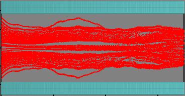
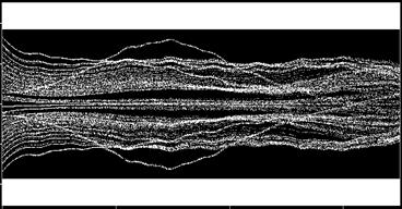
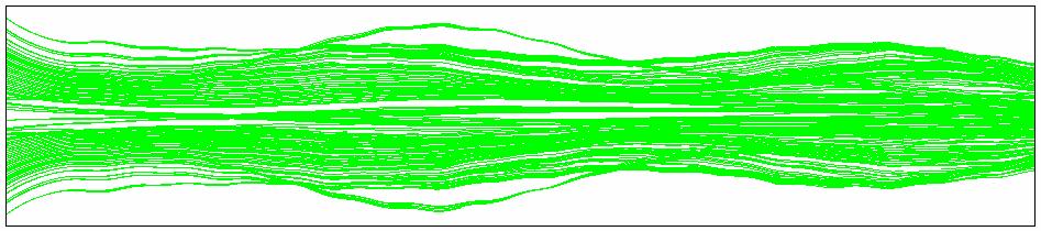
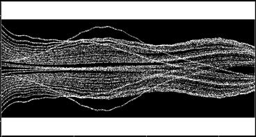
34 Long 2D 2x drift tube runs for the klystron (B=390G Solenoid) shows stable operation at 10MW Slide 34

35 Long 2D 2x drift tube runs for the klystron (B=390G RMS PCM) shows stable operation Without RF With RF, Just shy of 10MW, in process of fine tuning Slide 35
36 BSD Testing Alteration of original plan to validate latest TE mode interception data for a 2-cavity system 3500 Time to Interception (ns) PPM 2D (RMS, 1x Drift) PPM 3D (RMS, 1x Drift) Magnetic Field (G) Point much easier to build now than solenoid, many parts in house, keeps plan on track Slide 36

37 BSD test to begin Monday, May 11 Slide 37
38 Summary Challenges - Everything is 3D! Good 1, 2 & 3D code agreement BSD testing this Monday 2-Cavity PCM transport BSD test coming next Plug compatible alternative for ILC source PCM preference, solenoid backup TE mode: increase drift tube and field Design meets spec, now need to build it Slide 38
X-Band Klystron Development at
 X-Band Klystron Development at SLAC Slide 1 The Beginning X-band klystron work began at SLAC in the mid to late 80 s to develop high frequency (4x SLAC s-band), high power RF sources for the linear collider
Development of Multiple Beam Guns for High Power RF Sources for Accelerators and Colliders
 SLAC-PUB-10704 Development of Multiple Beam Guns for High Power RF Sources for Accelerators and Colliders R. Lawrence Ives*, George Miram*, Anatoly Krasnykh @, Valentin Ivanov @, David Marsden*, Max Mizuhara*,
A HIGH POWER LONG PULSE HIGH EFFICIENCY MULTI BEAM KLYSTRON
 A HIGH POWER LONG PULSE HIGH EFFICIENCY MULTI BEAM KLYSTRON A.Beunas and G. Faillon Thales Electron Devices, Vélizy, France S. Choroba DESY, Hamburg, Germany Abstract THALES ELECTRON DEVICES has developed
INFN School on Electron Accelerators. RF Power Sources and Distribution
 INFN School on Electron Accelerators 12-14 September 2007, INFN Sezione di Pisa Lecture 7b RF Power Sources and Distribution Carlo Pagani University of Milano INFN Milano-LASA & GDE The ILC Double Tunnel
Evaluation of Performance, Reliability, and Risk for High Peak Power RF Sources from S-band through X-band for Advanced Accelerator Applications
 Evaluation of Performance, Reliability, and Risk for High Peak Power RF Sources from S-band through X-band for Advanced Accelerator Applications Michael V. Fazio C. Adolphsen, A. Jensen, C. Pearson, D.
45 MW, 22.8 GHz Second-Harmonic Multiplier for High-Gradient Tests*
 US High Gradient Research Collaboration Workshop. SLAC, May 23-25, 2007 45 MW, 22.8 GHz Second-Harmonic Multiplier for High-Gradient Tests* V.P. Yakovlev 1, S.Yu. Kazakov 1,2, and J.L. Hirshfield 1,3 1
DEVELOPMENT OF X-BAND KLYSTRON TECHNOLOGY AT SLAC
 DEVELOPMENT OF X-BAND KLYSTRON TECHNOLOGY AT SLAC George Caryotakis, Stanford Linear Accelerator Center P.O. Box 4349 Stanford, CA 94309 Abstract * The SLAC design for a 1-TeV collider (NLC) requires klystrons
RF Power Generation II
 RF Power Generation II Klystrons, Magnetrons and Gyrotrons Professor R.G. Carter Engineering Department, Lancaster University, U.K. and The Cockcroft Institute of Accelerator Science and Technology Scope
Tutorial: Trak design of an electron injector for a coupled-cavity linear accelerator
 Tutorial: Trak design of an electron injector for a coupled-cavity linear accelerator Stanley Humphries, Copyright 2012 Field Precision PO Box 13595, Albuquerque, NM 87192 U.S.A. Telephone: +1-505-220-3975
DESIGN AND PERFORMANCE OF L-BAND AND S-BAND MULTI BEAM KLYSTRONS
 DESIGN AND PERFORMANCE OF L-BAND AND S-BAND MULTI BEAM KLYSTRONS Y. H. Chin, KEK, Tsukuba, Japan. Abstract Recently, there has been a rising international interest in multi-beam klystrons (MBK) in the
Dark current and multipacting trajectories simulations for the RF Photo Gun at PITZ
 Dark current and multipacting trajectories simulations for the RF Photo Gun at PITZ Introduction The PITZ RF Photo Gun Field simulations Dark current simulations Multipacting simulations Summary Igor Isaev
Detailed Design Report
 Detailed Design Report Chapter 4 MAX IV Injector 4.6. Acceleration MAX IV Facility CHAPTER 4.6. ACCELERATION 1(10) 4.6. Acceleration 4.6. Acceleration...2 4.6.1. RF Units... 2 4.6.2. Accelerator Units...
Development of klystrons with ultimately high - 90% RF power production efficiency
 Development of klystrons with ultimately high - 90% RF power production efficiency A. Baikov (MUFA), I. Syratchev (CERN), C. Lingwood, D. Constable (Lancaster University) Introduction FCC has high power
4.4 Injector Linear Accelerator
 4.4 Injector Linear Accelerator 100 MeV S-band linear accelerator based on the components already built for the S-Band Linear Collider Test Facility at DESY [1, 2] will be used as an injector for the CANDLE
CEPC Klystron Development
 CEPC Klystron Development Zusheng Zhou On behalf of High Efficiency RF Source R&D Collaboration Institute of High Energy Physics Sep. 26, 2018, HKUST, Hong Kong 1 Outline Strategy and plan 650MHz/800kW
Pulsed Klystrons for Next Generation Neutron Sources Edward L. Eisen - CPI, Inc. Palo Alto, CA, USA
 Pulsed Klystrons for Next Generation Neutron Sources Edward L. Eisen - CPI, Inc. Palo Alto, CA, USA Abstract The U.S. Department of Energy (DOE) Office of Science has funded the construction of a new accelerator-based
A SHEET-BEAM KLYSTRON PAPER DESIGN
 SLAC-PUB-8967 A SHEET-BEAM KLYSTRON PAPER DESIGN G. Caryotakis Stanford Linear Accelerator Center, Stanford University, Stanford Ca. 94309 Abstract What may be the first detailed cold test and computer
KLYSTRON GUN ARCING AND MODULATOR PROTECTION
 SLAC-PUB-10435 KLYSTRON GUN ARCING AND MODULATOR PROTECTION S.L. Gold Stanford Linear Accelerator Center (SLAC), Menlo Park, CA USA Abstract The demand for 500 kv and 265 amperes peak to power an X-Band
DESIGN AND TECHNOLOGICAL ASPECTS OF KLYSTRON DEVELOPMENT
 DESIGN AND TECHNOLOGICAL ASPECTS OF KLYSTRON DEVELOPMENT Dr. L M Joshi Emeritus Scientist CSIR-CEERI, PILANI lmj1953@gmail.com 22 February 2017 IPR 1 Schemetic Diagram 22 February 2017 IPR 2 Basic Principle
NEW METHOD FOR KLYSTRON MODELING
 NEW METHOD FOR KLYSTRON MODELING Y. H. Chin, KEK, 1-1 Oho, Tsukuba-shi, Ibaraki-ken, 35, Japan Abstract We have developed a new method for a realistic and more accurate simulation of klystron using the
Effect on Beam Current on varying the parameters of BFE and Control Anode of a TWT Electron Gun
 International Journal of Photonics. ISSN 0974-2212 Volume 7, Number 1 (2015), pp. 1-9 International Research Publication House http://www.irphouse.com Effect on Beam Current on varying the parameters of
Final Report. U.S. Department of Energy Grant Number DE-FG02-04ER83916
 Development of a 200 MHz Multiple Beam Klystron Final Report U.S. Department of Energy Grant Number DE-FG02-04ER83916 July 2004 - March 2005 Calabazas Creek Research, Inc. 20937 Comer Drive Saratoga, CA
Next Linear Collider. The 8-Pack Project. 8-Pack Project. Four 50 MW XL4 X-band klystrons installed on the 8-Pack
 The Four 50 MW XL4 X-band klystrons installed on the 8-Pack The Demonstrate an NLC power source Two Phases: 8-Pack Phase-1 (current): Multi-moded SLED II power compression Produce NLC baseline power: 475
RF plans for ESS. Morten Jensen. ESLS-RF 2013 Berlin
 RF plans for ESS Morten Jensen ESLS-RF 2013 Berlin Overview The European Spallation Source (ESS) will house the most powerful proton linac ever built. The average beam power will be 5 MW which is five
TECHNICAL SPECIFICATION Multi-beam S-band Klystron type BT267
 TECHNICAL SPECIFICATION Multi-beam S-band Klystron type BT267 The company was created for the development and manufacture of precision microwave vacuum-electron-tube devices (VETD). The main product areas
THE NEXT LINEAR COLLIDER TEST ACCELERATOR: STATUS AND RESULTS * Abstract
 SLAC PUB 7246 June 996 THE NEXT LINEAR COLLIDER TEST ACCELERATOR: STATUS AND RESULTS * Ronald D. Ruth, SLAC, Stanford, CA, USA Abstract At SLAC, we are pursuing the design of a Next Linear Collider (NLC)
X-Band klystron development at the Stanford Linear Accelerator Center
 SLAC-PUB-8346 March 2000 X-Band klystron development at the Stanford Linear Accelerator Center D. Sprehn, G. Caryotakis, E. Jongewaard, R. M. Phillips, and A. Vlieks Stanford Linear Accelerator Center
Oak Ridge Spallation Neutron Source Proton Power Upgrade Project and Second Target Station Project
 Oak Ridge Spallation Neutron Source Proton Power Upgrade Project and Second Target Station Project Workshop on the future and next generation capabilities of accelerator driven neutron and muon sources
150-MW S-Band Klystron Program at the Stanford Linear Accelerator Center1
 SLAC Pub 7232 July 1996 4 15-MW S-Band Klystron Program at the Stanford Linear Accelerator Center1 D. SPREHN, G. CARYOTAKS, and R. M. PHLLPS Stanford Linear Accelerator Center Stanford Universiw, Stanford,
Solid State Modulators for X-Band Accelerators
 Solid State Modulators for X-Band Accelerators John Kinross-Wright Diversified Technologies, Inc. Bedford, Massachusetts DTI X-Band Experience Developed and built two completely different NLC-class modulator
This work was supported by FINEP (Research and Projects Financing) under contract
 under contract") MODELING OF A GRIDDED ELECTRON GUN FOR TRAVELING WAVE TUBES C. C. Xavier and C. C. Motta Nuclear & Energetic Research Institute, São Paulo, SP, Brazil University of São Paulo, São Paulo, SP, Brazil Abstract
MODELING OF A GRIDDED ELECTRON GUN FOR TRAVELING WAVE TUBES C. C. Xavier and C. C. Motta Nuclear & Energetic Research Institute, São Paulo, SP, Brazil University of São Paulo, São Paulo, SP, Brazil Abstract
IOT RF Power Sources for Pulsed and CW Linacs
 LINAC 2004 Lübeck, August 16 20, 2004 IOT RF Power Sources H. Bohlen, Y. Li, Bob Tornoe Communications & Power Industries Eimac Division, San Carlos, CA, USA Linac RF source property requirements (not
Pseudospark-sourced Micro-sized Electron Beams for High Frequency klystron Applications
 Pseudospark-sourced Micro-sized Electron Beams for High Frequency klystron Applications H. Yin 1*, D. Bowes 1, A.W. Cross 1, W. He 1, K. Ronald 1, A. D. R. Phelps 1, D. Li 2 and X. Chen 2 1 SUPA, Department
L-Band RF R&D. SLAC DOE Review June 15 th, Chris Adolphsen SLAC
 L-Band RF R&D SLAC DOE Review June 15 th, 2005 Chris Adolphsen SLAC International Linear Collider (ILC) RF Unit (TESLA TDR Layout) Gradient = 23.4 MV/m Bunch Spacing = 337 ns Fill Time = 420 µs Train Length
Low Frequency Gyrotrons for Fusion
 13th Joint Workshop on Electron Cyclotron Emission and Electron Cyclotron Resonance Heating Nizhny Novgorod, Russia May 17-20, 2004 РАН Low Frequency Gyrotrons for Fusion НПП ГИКОМ V.E. Zapevalov, Yu.K.
Design, Fabrication and Testing of Gun-Collector Test Module for 6 MW Peak, 24 kw Average Power, S-Band Klystron
 Available online www.ejaet.com European Journal of Advances in Engineering and Technology, 2014, 1(1): 11-15 Research Article ISSN: 2394-658X Design, Fabrication and Testing of Gun-Collector Test Module
Recent ITER-Relevant Gyrotron Tests
 Journal of Physics: Conference Series Recent ITER-Relevant Gyrotron Tests To cite this article: K Felch et al 2005 J. Phys.: Conf. Ser. 25 13 View the article online for updates and enhancements. Related
INTERNATIONAL JOURNAL OF ELECTRONICS AND COMMUNICATION ENGINEERING & TECHNOLOGY (IJECET)
") INTERNATIONAL JOURNAL OF ELECTRONICS AND COMMUNICATION ENGINEERING & TECHNOLOGY (IJECET) International Journal of Electronics and Communication Engineering & Technology (IJECET), ISSN 0976 6464(Print)
INTERNATIONAL JOURNAL OF ELECTRONICS AND COMMUNICATION ENGINEERING & TECHNOLOGY (IJECET) International Journal of Electronics and Communication Engineering & Technology (IJECET), ISSN 0976 6464(Print)
The PEFP 20-MeV Proton Linear Accelerator
 Journal of the Korean Physical Society, Vol. 52, No. 3, March 2008, pp. 721726 Review Articles The PEFP 20-MeV Proton Linear Accelerator Y. S. Cho, H. J. Kwon, J. H. Jang, H. S. Kim, K. T. Seol, D. I.
Experience with the Cornell ERL Injector SRF Cryomodule during High Beam Current Operation
 Experience with the Cornell ERL Injector SRF Cryomodule during High Beam Current Operation Matthias Liepe Assistant Professor of Physics Cornell University Experience with the Cornell ERL Injector SRF
CLIC Feasibility Demonstration at CTF3
 CLIC Feasibility Demonstration at CTF3 Roger Ruber Uppsala University, Sweden, for the CLIC/CTF3 Collaboration http://cern.ch/clic-study LINAC 10 MO303 13 Sep 2010 The Key to CLIC Efficiency NC Linac for
Operating Experience and Reliability Improvements on the 5 kw CW Klystron at Jefferson Lab
 Operating Experience and Reliability Improvements on the 5 kw CW Klystron at Jefferson Lab Richard Walker & Richard Nelson Jefferson Lab, Newport News VA Jefferson Lab is a $600M Department of Energy facility
Experimental results and recent developments on the EU 2 MW 170 GHz coaxial cavity gyrotron for ITER
 Experimental results and recent developments on the EU 2 MW 170 GHz coaxial cavity gyrotron for ITER S. Kern 1, J.-P. Hogge 2, S. Alberti 2, K. Avramides 3, G. Gantenbein 1, S. Illy 1, J. Jelonnek 1, J.
TOSHIBA Industrial Magnetron E3328
 TOSHIBA E3328 is a fixed frequency continuous wave magnetron intended for use in the industrial microwave heating applications. The average output power is 3kW in the frequency range from 2450 to 2470
THE X-BAND KLYSTRON PROGRAM AT SLAC'
 SLAC-PUB-7 146 April 1996 THE X-BAND KLYSTRON PROGRAM AT SLAC' George Caryotakis ' Stanford Linear Accelerator Center Stanford University, Stanford, CA 9439 The X-band r f source development at SLAC can
A New 4MW LHCD System for EAST
 1 EXW/P7-29 A New 4MW LHCD System for EAST Jiafang SHAN 1), Yong YANG 1), Fukun LIU 1), Lianmin ZHAO 1) and LHCD Team 1) 1) Institute of Plasma Physics, Chinese Academy of Sciences, Hefei, China E-mail
LCLS RF Reference and Control R. Akre Last Update Sector 0 RF and Timing Systems
 LCLS RF Reference and Control R. Akre Last Update 5-19-04 Sector 0 RF and Timing Systems The reference system for the RF and timing starts at the 476MHz Master Oscillator, figure 1. Figure 1. Front end
Klystron Tubes. Two forms of such a device, also called linear beam klystron, are given in the following figure.
 Klystron Tubes Go to the klystron index The principle of velocity-variation, first used in Heil oscillators, was also used in other microwave amplifying and oscillating tubes. The application for klystron
XFEL High Power RF System Recent Developments
 XFEL High Power RF System Recent Developments for the XFEL RF Group Outline XFEL RF System Requirements Overview Basic Layout RF System Main Components Multibeam Klystrons Modulator RF Waveguide Distribution
RF Design of the LCLS Gun C.Limborg, Z.Li, L.Xiao, J.F. Schmerge, D.Dowell, S.Gierman, E.Bong, S.Gilevich February 9, 2005
 RF Design of the LCLS Gun C.Limborg, Z.Li, L.Xiao, J.F. Schmerge, D.Dowell, S.Gierman, E.Bong, S.Gilevich February 9, 2005 Summary Final dimensions for the LCLS RF gun are described. This gun, referred
J/NLC Progress on R1 and R2 Issues. Chris Adolphsen
 J/NLC Progress on R1 and R2 Issues Chris Adolphsen Charge to the International Linear Collider Technical Review Committee (ILC-TRC) To assess the present technical status of the four LC designs at hand,
LASERTRON SIMULATION WITH A TWO-GAP OUTPUT CAVITY*
 SLAC/AP-41 April 1985 CAP) LASERTRON SMULATON WTH A TWO-GAP OUTPUT CAVTY* W. B. Herrmannsfeldt Stanford Linear Accelerator Center Stanford University, Stanford, California 94305 Abstract: With a two-gap
These tests will be repeated for different anode positions. Radiofrequency interaction measurements will be made subsequently. A.
 VI. MICROWAVE ELECTRONICS Prof. L. D. Smullin Prof. L. J. Chu A. Poeltinger Prof. H. A. Haus L. C. Bahiana C. W. Rook, Jr. Prof. A. Bers R. J. Briggs J. J. Uebbing D. Parker A. HIGH-PERVEANCE HOLLOW ELECTRON-BEAM
!"!3
 Abstract A single-mode 500 MHz superconducting cavity cryomodule has been developed at Cornell for the electronpositron collider/synchrotron light source CESR. The Cornell B-cell cavity belongs to the
The field cage for a large TPC prototype
 EUDET The field cage for a large TPC prototype T.Behnke, L. Hallermann, P. Schade, R. Diener December 7, 2006 Abstract Within the EUDET Programme, the FLC TPC Group at DESY in collaboration with the Department
Linac 4 Instrumentation K.Hanke CERN
 Linac 4 Instrumentation K.Hanke CERN CERN Linac 4 PS2 (2016?) SPL (2015?) Linac4 (2012) Linac4 will first inject into the PSB and then can be the first element of a new LHC injector chain. It will increase
Towards an X-Band Power Source at CERN and a European Structure Test Facility
 Towards an X-Band Power Source at CERN and a European Structure Test Facility Erk Jensen and Gerry McMomagle CERN The X-Band Accelerating Structure Design and Test-Program Workshop Day 2: Structure Testing
RF Solutions for Science.
 RF Solutions for Science www.thalesgroup.com State-of-the-art RF sources for your scientific needs High-power klystrons HIGH KLYSTRONS WITH RF LONG PULSE above 50 μs Thales has been one of the leading
RF POWER GENERATION FOR FUTURE LINEAR COLLIDERS* 1. Introduction
 SLAC-PUB-5282 June 1990 (A) RF POWER GENERATION FOR FUTURE LINEAR COLLIDERS* W. R. Fowkes, M. A. Allen, R. S. Callin, G. Caryotakis, K. R. Eppley, K. S. Fant, Z. D. Farkas, J. Feinstein, K. Ko, R. F. Koontz,
3 cerl. 3-1 cerl Overview. 3-2 High-brightness DC Photocathode Gun and Gun Test Beamline
 3 cerl 3-1 cerl Overview As described before, the aim of the cerl in the R&D program includes the development of critical components for the ERL, as well as the construction of a test accelerator. The
LHC Beam Instrumentation Further Discussion
 LHC Beam Instrumentation Further Discussion LHC Machine Advisory Committee 9 th December 2005 Rhodri Jones (CERN AB/BDI) Possible Discussion Topics Open Questions Tune measurement base band tune & 50Hz
The SLAC Polarized Electron Source *
 SLAC-PUB-9509 October 2002 The SLAC Polarized Electron Source * J. E. Clendenin, A. Brachmann, T. Galetto, D.-A. Luh, T. Maruyama, J. Sodja, and J. L. Turner Stanford Linear Accelerator Center, 2575 Sand
High Brightness Injector Development and ERL Planning at Cornell. Charlie Sinclair Cornell University Laboratory for Elementary-Particle Physics
 High Brightness Injector Development and ERL Planning at Cornell Charlie Sinclair Cornell University Laboratory for Elementary-Particle Physics June 22, 2006 JLab CASA Seminar 2 Background During 2000-2001,
PEP II Design Outline
 PEP II Design Outline Balša Terzić Jefferson Lab Collider Review Retreat, February 24, 2010 Outline General Information Parameter list (and evolution), initial design, upgrades Collider Ring Layout, insertions,
CNT FIELD EMISSION CATHODE CATALOG. XinRay Systems Inc. April 2014
 CNT FIELD EMISSION CATHODE CATALOG April 2014 Version 1 1 TABLE OF CONTENTS: 1. ABBREVIATIONS... 2 2. INTRODUCTION... 3 3. PRODUCT AT A GLANCE... 6 4. CARBON NANOTUBE (CNT) CATHODE INFORMATION CHART*...
Conceptual Design for the New RPI 2020 Linac
 !! SLAC&PUB&16137! Conceptual Design for the New RPI 2020 Linac RPI 2020 Linac Design Study Group October 29, 2014 Prepared for BMPC-KAPL under purchase order number 103313 by SLAC National Accelerator
w. B. HERRMANNSFELDT and K. R. EPPLEY
 Particle Accelerators, 199, Vol. 3, pp. 197-29 Reprints available directly from the publisher Photocopying permitted by license only 199 Gordon and Breach, Science Publishers, Inc. Printed in the United
The Elettra Storage Ring and Top-Up Operation
 The Elettra Storage Ring and Top-Up Operation Emanuel Karantzoulis Past and Present Configurations 1994-2007 From 2008 5000 hours /year to the users 2010: Operations transition year Decay mode, 2 GeV (340mA)
SLS RF operation report 2003
 SLS RF operation report 2003 M. Pedrozzi, Jean-Yves Raguin Paul Scherrer Institute, 5232 Villigen PSI, Switzerland SUMMARY LINAC report SR Superconducting Third Harmonic system report SR 500 MHz system
Design of a 50 MW Klystron at X-Band*
 SLAC-PUB-954676 July 1995 Background Eight Next Linear Collider (NLC) prototype klystrons, known as the XC-series Design of a 50 MW Klystron at X-Band* klystrons, have been evaluated at SLAC with a goal
18 GHz, 2.2 kw KLYSTRON GENERATOR GKP 24KP 18GHz WR62 3x400V
 18 GHz, 2.2 kw KLYSTRON GENERATOR GKP 24KP 18GHz WR62 3x400V With its characteristics of power stability whatever the load, very fast response time when pulsed (via external modulated signal), low ripple,
SLAC R&D Program for a Polarized RF Gun
 ILC @ SLAC R&D Program for a Polarized RF Gun SLAC-PUB-11657 January 2006 (A) J. E. CLENDENIN, A. BRACHMANN, D. H. DOWELL, E. L. GARWIN, K. IOAKEIMIDI, R. E. KIRBY, T. MARUYAMA, R. A. MILLER, C. Y. PRESCOTT,
Experimental Results of the Coaxial Multipactor Experiment. T.P. Graves, B. LaBombard, S.J. Wukitch, I.H. Hutchinson PSFC-MIT
 Experimental Results of the Coaxial Multipactor Experiment T.P. Graves, B. LaBombard, S.J. Wukitch, I.H. Hutchinson PSFC-MIT Summary A multipactor discharge is a resonant condition for electrons in an
RF Power Klystrons & 20 Year Look. R. Nelson 7/15/15
 RF Power Klystrons & 20 Year Look R. Nelson 7/15/15 RF Power klystrons 8 x 13 kw klystrons Page 2 Why A klystron? Best (only) choice at the time - 1988 Easy to use: Input (drive), output (to CM), power
14 GHz, 2.2 kw KLYSTRON GENERATOR GKP 22KP 14GHz WR62 3x400V
 14 GHz, 2.2 kw KLYSTRON GENERATOR GKP 22KP 14GHz WR62 3x400V With its characteristics of power stability independent of the load, very fast response time when pulsed (via external modulated signal), low
EPJ Web of Conferences 95,
 EPJ Web of Conferences 95, 04012 (2015) DOI: 10.1051/ epjconf/ 20159504012 C Owned by the authors, published by EDP Sciences, 2015 The ELENA (Extra Low Energy Antiproton) project is a small size (30.4
SLAC-PUB-2380 August 1979 (A)
") 1979 LINEAR ACCELERATOR CONFERENCE RF SOURCES DEVELOPMENTS* Jean V. Lebacqz Stanford Linear Accelerator Center Stanford University, Stanford, California 94305 SLAC-PUB-2380 August 1979 (A) Abstract The
1979 LINEAR ACCELERATOR CONFERENCE RF SOURCES DEVELOPMENTS* Jean V. Lebacqz Stanford Linear Accelerator Center Stanford University, Stanford, California 94305 SLAC-PUB-2380 August 1979 (A) Abstract The
Lecture 17 Microwave Tubes: Part I
 Basic Building Blocks of Microwave Engineering Prof. Amitabha Bhattacharya Department of Electronics and Communication Engineering Indian Institute of Technology, Kharagpur Lecture 17 Microwave Tubes:
CPI Gyrotrons For Fusion EC Heating
 CPI Gyrotrons For Fusion EC Heating H. Jory, M. Blank, P. Borchard, P. Cahalan, S. Cauffman, T. S. Chu, and K. Felch CPI, Microwave Power Products Division 811 Hansen Way, Palo Alto, CA 94303, USA e-mail:
The FLASH objective: SASE between 60 and 13 nm
 Injector beam control studies winter 2006/07 talk from E. Vogel on work performed by W. Cichalewski, C. Gerth, W. Jalmuzna,W. Koprek, F. Löhl, D. Noelle, P. Pucyk, H. Schlarb, T. Traber, E. Vogel, FLASH
LCLS Injector Technical Review
 LCLS Injector Technical Review Stanford Linear Accelerator Center November 3&4 2003 Review Committee Members: Prof. Patrick O Shea Chair University of Maryland Dr. E. Colby Stanford Linear Accelerator
A Unique Power Supply for the PEP II Klystron at SLAC*
 I : SLAC-PUB-7591 July 1997 A Unique Power Supply for the PEP II Klystron at SLAC* R. Case1 and M. N. Nguyen Stanford Linear Accelerator Center Stanford University, Stanford, CA 94309 Presented at the
IOT OPERATIONAL EXPERIENCE ON ALICE AND EMMA AT DARESBURY LABORATORY
 IOT OPERATIONAL EXPERIENCE ON ALICE AND EMMA AT DARESBURY LABORATORY A. Wheelhouse ASTeC, STFC Daresbury Laboratory ESLS XVIII Workshop, ELLETRA 25 th 26 th November 2010 Contents Brief Description ALICE
PEP-I1 RF Feedback System Simulation
 SLAC-PUB-10378 PEP-I1 RF Feedback System Simulation Richard Tighe SLAC A model containing the fundamental impedance of the PEP- = I1 cavity along with the longitudinal beam dynamics and feedback system
Summary of the 1 st Beam Line Review Meeting Injector ( )
") Summary of the 1 st Beam Line Review Meeting Injector (23.10.2006) 15.11.2006 Review the status of: beam dynamics understanding and simulations completeness of beam line description conceptual design of
Summary of the 1 st Beam Line Review Meeting Injector (23.10.2006) 15.11.2006 Review the status of: beam dynamics understanding and simulations completeness of beam line description conceptual design of
Upgrading LHC Luminosity
 1 Upgrading LHC Luminosity 2 Luminosity (cm -2 s -1 ) Present (2011) ~2 x10 33 Beam intensity @ injection (*) Nominal (2015?) 1 x 10 34 1.1 x10 11 Upgraded (2021?) ~5 x10 34 ~2.4 x10 11 (*) protons per
DELIVERY RECORD. Location: Ibaraki, Japan
 DELIVERY RECORD Client: Japan Atomic Energy Agency (JAEA) High Energy Accelerator Research Organization (KEK) Facility: J-PARC (Japan Proton Accelerator Research Complex) Location: Ibaraki, Japan 1 October
RF Upgrades & Experience At JLab. Rick Nelson
 RF Upgrades & Experience At JLab Rick Nelson Outline Background: CEBAF / Jefferson Lab History, upgrade requirements & decisions Progress & problems along the way Present status Future directions & concerns
Current status of XFEL/SPring-8 project and SCSS test accelerator
 Current status of XFEL/SPring-8 project and SCSS test accelerator Takahiro Inagaki for XFEL project in SPring-8 inagaki@spring8.or.jp Outline (1) Introduction (2) Key technology for compactness (3) Key
UNIT-3 Part A. 2. What is radio sonde? [ N/D-16]
![UNIT-3 Part A. 2. What is radio sonde? [ N/D-16]](/thumbs/88/116973079.jpg "UNIT-3 Part A. 2. What is radio sonde? [ N/D-16]") UNIT-3 Part A 1. What is CFAR loss? [ N/D-16] Constant false alarm rate (CFAR) is a property of threshold or gain control devices that maintain an approximately constant rate of false target detections
UNIT-3 Part A 1. What is CFAR loss? [ N/D-16] Constant false alarm rate (CFAR) is a property of threshold or gain control devices that maintain an approximately constant rate of false target detections
CHAPTER 4: HIGH ENERGY X-RAY GENERATORS: LINEAR ACCELERATORS. Jason Matney, MS, PhD
 CHAPTER 4: HIGH ENERGY X-RAY GENERATORS: LINEAR ACCELERATORS Jason Matney, MS, PhD Objectives Medical electron linear accelerators (often shortened to LINAC) The Basics Power Supply Magnetron/Klystron
Report on the LCLS Injector Technical Review
 Report on the LCLS Injector Technical Review Stanford Linear Accelerator Center November 3&4, 2003 Committee Members Prof. Patrick G. O Shea, Chair, University of Maryland Dr. Eric Colby, Stanford Linear
Optimization of a triode-type cusp electron gun for a W-band gyro-twa
 Optimization of a triode-type cusp electron gun for a W-band gyro-twa Liang Zhang, 1, a) Craig R. Donaldson, 1 and Wenlong He 1 Department of Physics, SUPA, University of Strathclyde, Glasgow, G4 0NG,
Recent developments in cyclotrons for proton therapy at IBA
 Recent developments in cyclotrons for proton therapy at IBA Yves Jongen. Founder & CRO IBA sa We Protect, Enhance and Save Lives. A typical PT center 30-55 millions for equipment 45-100 millions for the
SECTION I INTRODUCTION
 SECTION I INTRODUCTION This handbook analyzes the operation of EIMAC power grid tubes and provides design and application information to assist the user of these tubes to achieve long tube life, maximum
ILC RF System R&D. Chris Adolphsen, SLAC. Section of 1.3 GHz SC Linac. June 29, 2007 PAC07 Talk FRYC01
 ILC RF System R&D Chris Adolphsen, SLAC June 29, 2007 PAC07 Talk FRYC01 Section of 1.3 GHz SC Linac ILC Main Linac RF Unit (1 of 560) RF System Gradient = 31.5 MV/m Rep Rate = 5 Hz Beam Current = 9.0 ma
RF considerations for SwissFEL
 RF considerations for H. Fitze in behalf of the PSI RF group Workshop on Compact X-Ray Free Electron Lasers 19.-21. July 2010, Shanghai Agenda Introduction RF-Gun Development C-band development Summary
Performance of a DC GaAs photocathode gun for the Jefferson lab FEL
 Nuclear Instruments and Methods in Physics Research A 475 (2001) 549 553 Performance of a DC GaAs photocathode gun for the Jefferson lab FEL T. Siggins a, *, C. Sinclair a, C. Bohn b, D. Bullard a, D.
650MHz/800kW Klystron Development at IHEP
 650MHz/800kW Klystron Development at IHEP Shilun Pei, IHEP On behalf of HERSC (High Efficiency RF Source R&D Collaboration) in China Presentation at the IAS Program on High Energy Physics January 22, 2018,
Teltron Delection Tube D
 Teltron Delection Tube D 1011119 Overview The electron-beam deflection tube is intended for investigating the deflection of electron beams in electrical and magnetic fields. It can be used to estimate