Instruction manual FA1...
|
|
|
- Megan Richardson
- 5 years ago
- Views:
Transcription

1 Instruction manual FA1... NAN-KD-0006-en_V /09/2015
2 Issue NORIS Automation GmbH Issue Information on issue Document ID NAN-KD-0006-de/en Issue V02.04 Date August 2015 Issued by NORIS Automation GmbH Muggenhofer Str Nuremberg Germany Phone: Fax: info@noris-group.com 2 / 49 Instruction manual FA1...
3 NORIS Automation GmbH Table of contents Table of contents 1 General information 5 2 General information on this instruction manual Scope of validity Subject of the operating instructions Design and use of safety and warning notes Scope of delivery Accessories and spare parts Type code 9 Type code FAJ11 9 Type code FAJ12 10 Type code FAH11 11 Type code FAH12 12 Type code FAHZ Product description Scope of application Measuring principle Peculiarities and differences Speed sensor design General structure Connection variants Signal types and output level Elementary circuit diagram 19 4 Technical data Technical data type FAH11 (Extract) Technical data type FAH12 (Extract) Technical data type FAJ11 (Extract) Technical data type FAJ12 (Extract) Technical data FAHZ11 (Extract) 24 5 Installation Information on avoiding faults and damage Preparing for installation Dimensions Checking the scanning object Checking the installation holes Preparing tools and ressources Mounting speed sensors Mounting speed sensors with inductive-magnetic principle, type FAJxx Mounting speed sensors with differential Hall principle, type FAHxx Connection and cable laying Connection concept Important information on connection and cable installation Connection variants 37 Instruction manual FA1... iii
4 Table of contents NORIS Automation GmbH 6 Commissioning Tools and equipment Checking the operating voltage Checking the power consumption Checking operation Checking the phase angle Checking the shielding 44 7 Maintenance 45 8 De-installation and disposal 46 9 Troubleshooting Recommended procedure Considerations for troubleshooting Frequent causes of fault Service 49 iv Instruction manual FA1...
5 NORIS Automation GmbH General information 1 1 General information Use for intended purpose The product may only be used for the applications specified in this document and in the technical documentation. Transportation with due care and attention, correct storage and installation as well as careful use and maintenance during operation of the product must be ensured to guarantee trouble-free and safe operation. The product must be used at all times in agreement with the technical specifications. In particular, compliance with the ambient conditions recommended in the technical documentation must be ensured. Installation, assembly, repair and maintenance work Installation, assembly, repair and maintenance work must be carried out exactly according to the installation and maintenance instructions applicable to the individual products in order to guarantee their functional reliability and avoid installation errors and damage. Installation, assembly, repair and maintenance work must only be performed by qualified and authorised technical personnel in accordance with the relevant documentation, especially the safety and warning information contained therein. Make sure that no excess parts (screws, tools, etc) are left behind in or on products after performing installation, assembly, repair or maintenance work. Non-compliance with this requirement may cause malfunctions and/or damage to the products or the system. Make sure a function test is carried out on completion of installation, assembly, repair and maintenance work to ensure trouble-free operation of the products. Suitable tools and equipment Only suitable tools and equipment, especially materials provided by NO- RIS, are to be used for installation, assembly, repair and maintenance work. Damaged products or components are to be replaced only by genuine NORIS components or parts. NORIS shall accept no liability whatsoever for any damage incurred as the result of using unauthorised spare parts. This will invalidate the warranty. Modification of products NORIS shall accept no liability whatsoever if unauthorised modifications have been made to the products. This will also invalidate the warranty. Therefore, consult our technical staff before undertaking any modifications. Appropriate storage and packaging Products that are sent in for repair must be appropriately packaged to prevent damage (from impacts, moisture, static charge, etc). Make sure that all spare parts are stored correctly. Refer to the corresponding technical information for further information. Instruction manual FA / 49
6 1 General information NORIS Automation GmbH Disclaimer We review the contents of our technical documentation at regular intervals to ensure it agrees with our products. Nevertheless, variations cannot be completely ruled out. NORIS therefore cannot guarantee complete agreement of the documentation contents with the hardware and software. Changes and corrections will be included in subsequent issues of the technical documentation. 6 / 49 Instruction manual FA1...
7 NORIS Automation GmbH General information on this instruction manual 2 2 General information on this instruction manual 2.1 Scope of validity This instruction manual applies to the Series 11 and 12 sensors listed below: Sensor type FAH11 FAH12 FAJ11 FAJ12 FAHZ11 Product revision B B C C D Important information on the use of this instruction manual and supplementary information Please note that the sensors are often adapted to customer-specific requirements. The connection cables, cable lengths, connectors etc. described in this instruction manual may vary in terms of the features on your specific product. Therefore always first refer to the information in the customer-specific drawing for installation, commissioning and operation. 2.2 Subject of the operating instructions The subject of these operating instructions is the installation, commissioning, operation and maintenance of Series 11 and 12 speed sensors. This manual also contains important troubleshooting information. Instruction manual FA / 49
8 2 General information on this instruction manual NORIS Automation GmbH 2.3 Design and use of safety and warning notes DANGER Warning about the type and source of danger that lead to serious injuries or even to death when disregarding the given precautions. Folgen CAUTION Warning about the type and source of danger that lead to minor physical injury when disregarding the given precautions. Folgen NOTICE Warning about the type and source of danger that lead to material damages when disregarding the given precautions. Folgen 2.4 Note on customer-specific scope of delivery Scope of delivery The scope of delivery of your product may vary from the specifications below. The scope of delivery is individually adapted to your specific requirements. In addition certain items are dependent on other factors, e.g. the number of retaining clips on the cable length, the size of the retaining clips on the calve diameter. Refer to the corresponding parts list for a detailed overview of the scope of delivery for your product. The standard scope of delivery contains: Speed sensor, packed in an polyethylene bag. 2 nuts for fixing the sensor Thread protection 2.5 Available accessories Available spare parts Accessories and spare parts In addition to the installation material, no further accessories are available for Series 11 and 12 speed sensors. Available spare parts include installation material and connectors. For detailed information please contact our Service department or marketing team at sales@noris-group.com. 8 / 49 Instruction manual FA1...
9 NORIS Automation GmbH General information on this instruction manual Type code Type code structure Type code FAJ11 FAJ A -S0 Example: FAJ A-S0 Nominal length L1 and L2 of the sensor tube Thread type Electrical connection Shielding Type code FAJ11- Nominal length 02 L1 = 60 mm, L2 = 5 mm 03 L1 = 80 mm, L2 = 5 mm 04 L1 = 100 mm, L2 = 20 mm 05 L1 = 120 mm, L2 = 40 mm Thread type 13 M14x1 22 M16x M18x1 23 M18x /8 18 UNF Electrical connection Shielding -A DIN43650-A, pin connector, 3 terminals + PE (solenoid valve30x30) -C MIL 14-5PN VG95234, pin connector, 5 terminals -E Euro M12x1, pin connector, 5 terminals, contact gold plated -H1 DIN72585 Bajonette, pin connector, 4 terminals, Coding 1(BK) -X03 Cable end with sheath length 0.5 m -X05 Cable end with sheath length 2.0 m -X06 Cable end with sheath length 3.0 m -X07 Cable end with sheath length 5.0 m -X08 Cable end with sheath length 7.5 m -X09 Cable end with sheath length 10.0 m Without code: Shielding is attached to the sensor housing -S0 Shielding is not attached to the sensor housing FAJ _ Example: FAJ A (preferred type) Preferred types Features marked with a symbol at the end of the line (see previous table) are preferred features. If you select a preferred feature for each placeholder, the device is specified as preferred type. Preferred types are available quickly from stock. Other types will be delivered according to scheduled appointments. Instruction manual FA / 49
10 2 General information on this instruction manual NORIS Automation GmbH Special types If our standard types do not correspond with your expectation, we are pleased to develop a special solution together with you. Type code FAJ12 Type code structure FAJ A -S0 Example: FAJ A-S0 Nominal length L1 and L2 of the sensor tube Thread type Electrical connection Shielding Type code FAJ12- Nominal length 02 L1 = 60 mm, L2 = 5 mm 03 L1 = 80 mm, L2 = 5 mm 04 L1 = 100 mm, L2 = 20 mm 05 L1 = 120 mm, L2 = 40 mm Thread type 13 M14x1 22 M16x M18x1 23 M18x /8 18 UNF Electrical connection Shielding -A DIN43650-A, pin connector, 3 terminals + PE (solenoid valve30x30) -C MIL 14-5PN VG95234, pin connector, 5 terminals -E Euro M12x1, pin connector, 5 terminals, contact gold plated -H1 DIN72585 Bajonette, pin connector, 4 terminals, Coding 1(BK) -X03 Cable end with sheath length 0.5 m -X05 Cable end with sheath length 2.0 m -X06 Cable end with sheath length 3.0 m -X07 Cable end with sheath length 5.0 m -X08 Cable end with sheath length 7.5 m -X09 Cable end with sheath length 10.0 m Without code: Shielding is attached to the sensor housing -S0 Shielding is not attached to the sensor housing FAJ _ Example: FAJ A 10 / 49 Instruction manual FA1...
11 NORIS Automation GmbH General information on this instruction manual 2 Type code structure Type code FAH11 FAH A -S0 Example: FAH A-S0 Nominal length L1 and L2 of the sensor tube Thread type Electrical connection Shielding Type code FAH11- (Standard types and preferred types) Nominal length 02 L1 = 60 mm, L2 = 5 mm 03 L1 = 80 mm, L2 = 5 mm 04 L1 = 100 mm, L2 = 20 mm 05 L1 = 120 mm, L2 = 40 mm Thread type 13 M14x1 22 M16x M18x1 23 M18x /8 18 UNF Electrical connection Shielding -A DIN43650-A, pin connector, 3 terminals + PE (solenoid valve30x30) -C MIL 14-5PN VG95234, pin connector, 5 terminals -E Euro M12x1, pin connector, 5 terminals, contact gold plated -H1 DIN72585 Bajonette, pin connector, 4 terminals, Coding 1(BK) -X03 Cable end with sheath length 0.5 m -X05 Cable end with sheath length 2.0 m -X06 Cable end with sheath length 3.0 m -X07 Cable end with sheath length 5.0 m -X08 Cable end with sheath length 7.5 m -X09 Cable end with sheath length 10.0 m Without code: Shielding is attached to the sensor housing -S0 Shielding is not attached to the sensor housing FAH _ Example: FAH A (preferred type) Preferred types Features marked with a symbol at the end of the line (see previous table) are preferred features. If you select a preferred feature for each placeholder, the device is specified as preferred type. Preferred types are available quickly from stock. Other types will be delivered according to scheduled appointments. Special types If our standard types do not correspond with your expectation, we are pleased to develop a special solution together with you. Instruction manual FA / 49
12 2 General information on this instruction manual NORIS Automation GmbH Type code structure Type code FAH12 FAH A -S0 Example: FAH A-S0 Nominal length L1 and L2 of the sensor tube Thread type Electrical connection Shielding Type code FAH12- Nominal length 02 L1 = 60 mm, L2 = 5 mm 03 L1 = 80 mm, L2 = 5 mm 04 L1 = 100 mm, L2 = 20 mm 05 L1 = 120 mm, L2 = 40 mm Thread type 13 M14x1 22 M16x M18x1 23 M18x /8 18 UNF Electrical connection Shielding -A DIN43650-A, pin connector, 3 terminals + PE (solenoid valve30x30) -C MIL 14-5PN VG95234, pin connector, 5 terminals -E Euro M12x1, pin connector, 5 terminals, contact gold plated -H1 DIN72585 Bajonette, pin connector, 4 terminals, Coding 1(BK) -X03 Cable end with sheath length 0.5 m -X05 Cable end with sheath length 2.0 m -X06 Cable end with sheath length 3.0 m -X07 Cable end with sheath length 5.0 m -X08 Cable end with sheath length 7.5 m -X09 Cable end with sheath length 10.0 m Without code: Shielding is attached to the sensor housing -S0 Shielding is not attached to the sensor housing FAH _ Example: FAH A 12 / 49 Instruction manual FA1...
13 NORIS Automation GmbH General information on this instruction manual 2 Type code structure Type code FAHZ11 FAHZ C -M10 -S0 Example: FAHZ C-M10-S0 Nominal length L1 and L2 of the sensor tube Thread type Electrical connection Module Shielding Type code FAHZ11- (Standard types and preferred types) Nominal length 02 L1 = 60 mm, L2 = 5 mm 03 L1 = 80 mm, L2 = 5 mm 04 L1 = 100 mm, L2 = 20 mm 05 L1 = 120 mm, L2 = 40 mm Thread type 15 M18x1 23 M18x1.5 Electrical connection -C MIL 14-5PN VG95234, pin connector, 5 terminals -E Euro M12x1, pin connector, 5 terminals, contact gold plated -X03 Cable end with sheath length 0.5 m -X05 Cable end with sheath length 2.0 m -X06 Cable end with sheath length 3.0 m -X07 Cable end with sheath length 5.0 m -X08 Cable end with sheath length 7.5 m -X09 Cable end with sheath length 10.0 m Module -M10 Module M1 -M12 Module M1.25 -M15 Module M1.5 Without code means module M2 -M25 Module M2.5 -M30 Module M3 Shielding Without code: Shielding is attached to the sensor housing -S0 Shielding is not attached to the sensor housing FAHZ _ Example: FAHZ E (preferred type) Preferred types Features marked with a symbol at the end of the line (see previous table) are preferred features. If you select a preferred feature for each placeholder, the device is specified as preferred type. Preferred types are available quickly from stock. Other types will be delivered according to scheduled appointments. Instruction manual FA / 49
14 2 General information on this instruction manual NORIS Automation GmbH Special types If our standard types do not correspond with your expectation, we are pleased to develop a special solution together with you. 14 / 49 Instruction manual FA1...
15 NORIS Automation GmbH Product description Product description Scope of application Series 11 and 12 speed sensors are mainly used in the following areas: Shipbuilding industry, transport technology and mechanical engineering. The sensors can be used for registering movements of any ferromagnetic components, such as gearwheels with various tooth shapes screw heads holes, apertures, grooves pulse bands on smooth shafts (accessories) 3.2 Measuring principle Series FAH sensors operate in accordance with the differential Hall principle: Two closely spaced Hall elements are located on the sensor chip. The field of the magnet generates a constant voltage in the Hall elements. Ferromagnetic objects with an interrupted surface moving past the Hall elements cause the Hall voltage to change. When the moving part covers a Hall element and the other does not, a differential voltage is generated to provide a measuring signal. The frequency of this signal is proportional to the speed of movement (rotational speed). The difference-hall-effect principle is direction sensitive. Series FAJ sensors operate in accordance with the inductive-magnetic principle: The measuring element consists of a sensing coil and an iron core with a permanent magnet mounted. Ferromagnetic objects with an interrupted surface as they pass the sensor cause the constant field of the magnet to be changed and induce a voltage in the sensing coil. The frequency of this signal is proportional to the speed of movement (rotational speed). The inductive-magnetic principle is direction-insensitive. Instruction manual FA / 49
16 3 Product description NORIS Automation GmbH 3.3 Peculiarities and differences The next table shows the features and differences between the sensors of the construction type 11 and 12. FAH11 FAH12 Robust housing: IP66/67 Robust and high quality housing: IP68 pressure-tight and individually tested at 5 bar (see technical data) Sensor tube: Brass Sensor tube: Stainless steel Measuring principle: Difference-hall-effect principle ence-hall-effect principle Measuring principle: Differ- Installation mode Direction-sensitive Installation mode Direction-sensitive FAJ11 Robust housing: IP66/67 Sensor tube: Brass Measuring principle: Inductive magnetic Installation mode Direction independent FAJ12 Robust and high quality housing: IP68 pressure-tight and individually tested at 5 bar (see technical data) Sensor tube: Stainless Steel Measuring principle: Inductive magnetic Installation mode Direction independent FAHZ11 Robust and high quality housing: IP68 pressure-tight and individually tested at 5 bar (see technical data) Sensor tube: Brass Measuring principle: Difference-hall-effect principle, 2 x square wave signals, level approx. UB Installation mode Direction-sensitive 16 / 49 Instruction manual FA1...

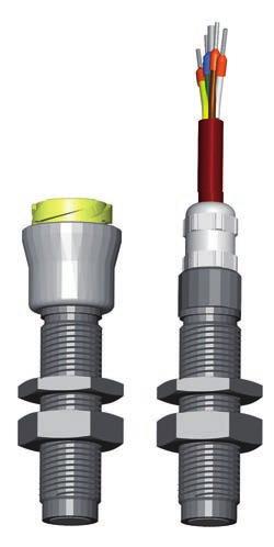
17 NORIS Automation GmbH Product description Speed sensor design General structure 1: FAx1x Design A B C D E Connecting plug (see connection variants) Threaded tube Counter nut Nut for fixation Sensor head (measuring area) Type series FAx11: Sensor tube: Brass Type series FAx12: Sensor tube: Stainless steel Information on customer-specific connections Connection variants Series 11 and 12 speed sensors are available with different connections. The connection variants are defined by the type code of the appropriate sensor type. Refer to the customer drawing for your connection variant. Standard: e. g. Euro M18x1 or cable end (see preferred types in type code). Instruction manual FA / 49
18 3 Product description NORIS Automation GmbH Signal types and output level Speed sensors type FAx1x (e. g. FAH11, FAH12, FAJ11, FAJ12) have a square wave output signal. 2: Signal type FAx1x_Q1 Output level FAH11 U High UB VDC, 10 ma, 24 C U Low VDC, 10 ma, 24 C Output level FAH12 U High UB VDC, 10 ma, 24 C U Low VDC, 10 ma, 24 C Output level FAJ11 U High UB VDC, 10 ma, 24 C U Low VDC, 10 ma, 24 C Output level FAJ12 U High UB VDC, 10 ma, 24 C U Low VDC, 10 ma, 24 C Speed sensors type FAHZ11 have two square wave output signals, Q2 is 90 face-shifted to Q1. Q1 Q2 90 t 3: FAHZ11 Phasendiagramm Output level FAHZ11 U High Per channel: UB VDC, 10 ma, 24 C U Low Per channel: VDC, 10 ma, 24 C 18 / 49 Instruction manual FA1...
19 NORIS Automation GmbH Product description Elementary circuit diagram +UB Push-pull output stage Note: NPN- and PNP-inputs can be connected. Ri Qn -UB (0V) Instruction manual FA / 49
20 4 Technical data NORIS Automation GmbH 4 Technical data 4.1 Technical data type FAH11 (Extract) Electrical connection Supply voltage U S Nominal voltage U NOM Current consumption I S Reverse voltage protection Over voltage protection Connection Recommended cable length VDC 24 VDC < 10 ma (without output current PNP) Yes Used cable cross section 0.33 mm², shielded Electrical output Output channels 1 Output signal Square wave signal Output stage Push-pull amplifier Galvanic separation One channel Output current (Sink) I L max. -50 ma Output PNP (Load) I L max. 50 ma Internal resistance 45 Ω Yes DIN 43650A, Mil14-5PN, Euro M12x1, DIN or cable end (see customer drawing) < 100 m Signal acquisition Measuring principle Scan type Scan object - material Scan object - distance Frequency range Difference-hall-effect principle Non-contacting Ferromagnetic materials Tooth wheel: Module m1 to m3; tooth face > 7 mm (spur gear DIN867) ; Hole: Ø 5 mm, web 2 mm, depth 4 mm ; Groove: Ø 4 mm, web 2 mm, depth 4 mm mm; recommended: 1.0 ± 0.5 mm ,000 Hz Environmental influences Operating temperature C 20 / 49 Instruction manual FA1...
21 NORIS Automation GmbH Technical data Technical data type FAH12 (Extract) Electrical connection Supply voltage U S Nominal voltage U NOM Current consumption I S Reverse voltage protection Over voltage protection Connection Recommended cable length VDC 24 VDC < 15 ma (without output current PNP) Yes Used cable cross section 0.33 mm², shielded Electrical output Output channels 1 Output signal Square wave signal Output stage Push-pull amplifier Galvanic separation One channel Output current (Sink) I L max. -50 ma Output PNP (Load) I L max. 50 ma Internal resistance 45 Ω Yes DIN 43650A, Mil14-5PN, Euro M12x1, DIN or cable end (see customer drawing) < 100 m Signal acquisition Measuring principle Scan type Scan object - material Scan object - distance Frequency range Difference-hall-effect principle Non-contacting Ferromagnetic materials Tooth wheel: Module m1 to m3; tooth face > 7 mm (spur gear DIN867) ; Hole: Ø 5 mm, web 2 mm, depth 4 mm ; Groove: Ø 4 mm, web 2 mm, depth 4 mm mm; recommended: 1.0 ± 0.5 mm ,000 Hz Environmental influences Operating temperature C (status LED near cable connection up to 100 C) Instruction manual FA / 49
22 4 Technical data NORIS Automation GmbH 4.3 Technical data type FAJ11 (Extract) Electrical connection Supply voltage U S Nominal voltage U NOM Current consumption I S Reverse voltage protection Over voltage protection Connection Recommended cable length VDC 24 VDC < 6 ma (without output current PNP) Yes Used cable cross section 0.33 mm², shielded Electrical output Output channels 1 Output signal Square wave signal Output stage Push-pull amplifier Galvanic separation One channel Output current (Sink) I L max. -50 ma Output PNP (Load) I L max. 50 ma Internal resistance 45 Ω Yes DIN 43650A, Mil14-5PN, Euro M12x1, DIN or cable end (see customer drawing) < 100 m Signal acquisition Measuring principle Scan type Scan object - material Scan object - distance Frequency range Inductive magnetic Non-contacting Ferromagnetic materials Tooth wheel: Module m1.5; tooth face width 5 mm (spur gear DIN867) ; Hole: Ø 5 mm, web 2 mm, depth 4 mm ; Groove: Ø 4 mm, web 2 mm, depth 4 mm See diagram See diagram; 5 Hz...10,000 Hz depending from module and scan distance; under optimal conditions up to 15 khz Environmental influences Operating temperature C 22 / 49 Instruction manual FA1...
23 NORIS Automation GmbH Technical data Technical data type FAJ12 (Extract) Electrical connection Supply voltage U S Nominal voltage U NOM Current consumption I S Reverse voltage protection Over voltage protection Connection Recommended cable length VDC 24 VDC < 7 ma (without output current PNP) Yes Used cable cross section 0.33 mm², shielded Electrical output Output channels 1 Output signal Square wave signal Output stage Push-pull amplifier Galvanic separation One channel Output current (Sink) I L max. -50 ma Output PNP (Load) I L max. 50 ma Internal resistance 45 Ω Yes DIN 43650A, Mil14-5PN, Euro M12x1, DIN or cable end (see customer drawing) < 100 m Signal acquisition Measuring principle Scan type Scan object - material Scan object - distance Frequency range Inductive magnetic Non-contacting Ferromagnetic materials Tooth wheel: Module m1.5; tooth face width 5 mm (spur gear DIN867) ; Hole: Ø 5 mm, web 2 mm, depth 4 mm ; Groove: Ø 4 mm, web 2 mm, depth 4 mm ; See diagram See diagram; 5 Hz...10,000 Hz depending from module and scan distance; under optimal conditions up to 15 khz Environmental influences Operating temperature C (status LED near cable connection up to 100 C) Instruction manual FA / 49
24 4 Technical data NORIS Automation GmbH 4.5 Technical data FAHZ11 (Extract) Electrical connection Supply voltage U B Nominal voltage U NENN Current consumption I B Reverse voltage protection Over voltage protection Connection Recommended cable length Used cable cross section Electrical output Output channels Output signal Output stage Galvanic separation Output current (Sink) I L Output PNP (Load) I L Internal resistance Signal acquisition Measuring principle Scan type Scan object - material Scan object - distance Frequency range VDC 15 VDC < 20 ma (without output current PNP) Yes Yes Mil14-5PN, Euro M12x1 or cable end (see customer drawing) < 100 m 0.33 mm², shielded 2 channels 2 x square wave signals, level approx. UB Push-pull amplifier No Per channel: max. 50 ma Per channel: max. 50 ma 50 Ω Difference-hall-effect principle Non-contacting Ferromagnetic materials Tooth wheel: Module m1 to m3; tooth face width > 7 mm (spur gear DIN867) Hole: Ø 5 mm, web 2 mm, depth 4 mmgroove: Ø 4 mm, web 2 mm, depth 4 mm mm; recommended: 1.0 ± 0.5 mm 0.2 Hz...20,000 Hz Environmental influences Operating temperature C 24 / 49 Instruction manual FA1...
25 NORIS Automation GmbH Installation Installation Information on avoiding faults and damage Protective Cap NOTICE Ensure that you remove the protective cap only when mounting the sensor. Otherwise the sensor may be damaged. At delivery the sensor is equipped with a protective cap to protect the measurement area and the electronic parts against mechanical and electrical hazard. NOTICE Ensure that the measurement area is not soiled. A soiled measurement area may lead to signal loss or even damage the sensor. Also note the recommendations in the maintenance section. Sensor mounting When mounting the sensor make sure that the screw connections are tightened appropriately. Therefore note the instructions in section "Installing the speed sensor [} 28]". NOTICE Use appropriate tools and do not apply excessive force to secure the sensor. The sensor may otherwise be damaged. Scanning distance Observe the permissible scanning distance. NOTICE Make sure that the specified scanning distance is maintained. Signal distortion and signal loss may occur or the sensor or the scanning object may even be damaged if the scanning distance is too small. Signal distortion and signal loss may also occur if the scanning distance is too great. Connection and securing connectors When installing the speed sensor, the data and information on the customer drawings always have priority over the information in this instruction manual. Instruction manual FA / 49
26 5 Installation NORIS Automation GmbH NOTICE Do not touch electronical parts of the sensor (connector pins, open cable end, etc.) without appropriate measures to ground your body (e. g. ESD wristband). Otherwise electrostatic discharge may damage the sensors electronic components. NOTICE Do not loosen the cable gland. Otherwise humidity and dust may damage the sensors electronic components. NOTICE The connections are to be made and connectors secured exactly as described on the technical drawings and in this manual. Incorrect wiring and incorrectly or inappropriately tightened screw connections can result in signal loss or damage to the sensor or connection. Cable installation NOTICE Make sure that the connection cable is installed correctly. Incorrectly installed connection cables can result in signal loss or damage to the sensor. NOTICE Note the minimum cable bending radius when laying the cable. Otherwise the connection cable may be damaged. READ You will find further information on cable installation under Connection and cable Installation. 26 / 49 Instruction manual FA1...
27 NORIS Automation GmbH Installation Preparing for installation Dimensions Explanation to the illustration Please note the possible combination of L1 and L2 for the nominal length in the type code. L1: 60, 80, 100, 120 mm L2: 5, 20, 40 mm G1: M18x1; M18x1.5; 5/8 18 UNF L1 L2 G Checking the scanning object NOTICE To ensure trouble-free operation, the scanning object must not be damaged. Damaged scanning objects can result in signal distortion, signal loss or even damage to the sensor. Make sure that the scanning object is in perfect condition. A. Check that the scanning object is undamaged (e.g. no scratches, material unevenness, etc.). If this is not the case, you must first rectify these faults before you continue with the installation of the sensor. Instruction manual FA / 49
28 5 Installation NORIS Automation GmbH Checking the installation holes Check the hole before you install the sensor. NOTICE A faulty hole can result in signal distortion, signal loss or even damage to the sensor. Therefore, carry out the following procedure: A. Check the installation tapped hole for the sensor tube. The hole must be without sharp edges and there must be no roughness on the surface of the hole. B. Fit the sensor carefully in the installation hole for testing purposes. The check is finished. You can now continue with the installation Preparing tools and ressources For installation prepare the following tools: Proper screw-wrenches according to the thread Torque wrench 5.3 Mounting speed sensors Mounting speed sensors with inductive-magnetic principle, type FAJxx Mount the sensor according to the following instructions: Prerequisite: The system is switched off. Prerequisite: The bore holes and the scanning object have been checked before mounting the sensor. A. Remove the thread protection. B. Screw the sensor carefully into the appropriate mounting bore hole and position the sensor exactly to the scanning object. The mounting of the sensor is not direction sensitive. C. Maintain the distance to the scanning object. D. If the scanning object is not visible: screw the speed sensor clockwise to the end stop (until the sensor touches the scanning object). NO- TICE! Attention: The scanning object must stand still!!! Now screw the sensor anti-clockwise according to its thread type to get the correct scanning distance (e. g. with thread type M18x1 one rotation correlates 1 mm, with thread type M18x1.5 one rotation correlates 1.5 mm, etc.). 28 / 49 Instruction manual FA1...
29 NORIS Automation GmbH Installation 5 The cover ration of sensor and scanning object should amount min. 2:3. E. With modules > m2 the recommended scanning distance has to be increased to get a valid output signal (see also the following diagram). 4: FAJ Diagram max. scanning distance - frequency NOTICE A too close scanning distance may lead to signal distortion, signal loss or may even damage the sensor. Thus, maintain the recommended scanning distance (> 0.2 mm). F. Fix the sensor with screw nut and counter screw nut. Screw the nuts with the correct torque (see next table). NOTICE Do not use disproportionately force to fix the screws. This may damage the sensor. This will invalidate the manufacturer s warranty. The mounting is finished. Thread Material Screw nut type Torque M18x1 Brass Nm Nm Stainless steel Nm 20 Nm M18x1,5 Stainless steel Nm Nm Instruction manual FA / 49
30 5 Installation NORIS Automation GmbH Thread Material Screw nut type Torque M16x1,5 Brass Nm M14x1 Brass Nm M14x1,5 Stainless steel Nm 5/8-18UNF Brass Nm 30 / 49 Instruction manual FA1...
31 NORIS Automation GmbH Installation Mounting speed sensors with differential Hall principle, type FAHxx Mount the sensor according to the following instructions: Prerequisite: The system is switched off. Prerequisite: The bore holes and the scanning object have been checked before mounting the sensor. A. Remove the thread protection. B. Screw the sensor carefully into the appropriate mounting bore hole and position the sensor exactly to the scanning object. C. Maintain the recommended distance to the scanning object "(see Section Technical Data) [} 20]". NOTICE A too close scanning distance may lead to signal distortion, signal loss or may even damage the sensor. Thus, maintain the recommended scanning distance (> 0.2 mm). D. If the scanning object is not visible: screw the speed sensor clockwise to the end stop (until the sensor touches the scanning object). NO- TICE! Attention: The scanning object must stand still!!! Now screw the sensor anti-clockwise according to its thread type to get the correct scanning distance (e. g. with thread type M18x1 one rotation correlates 1 mm, with thread type M18x1.5 one rotation correlates 1.5 mm, etc.). E. The mounting of this sensor type is direction sensitive. Note the position of the marking. Now screw the sensor clockwise or anti-clockwise (note the shortest screw direction) that the marking of the sensor is positioned in direction of rotation of the scanning object (see next Fig., Pos. B). Instruction manual FA / 49
32 5 Installation NORIS Automation GmbH B ±15 A The cover ration of sensor and scanning object should amount min. 2:3. F. Fix the sensor with screw nut and counter screw nut. Screw the nuts with the correct torque (see next table). NOTICE Do not use disproportionately force to fix the screws. This may damage the sensor. This will invalidate the manufacturer s warranty. The mounting is finished. Thread Material Screw nut type Torque M18x1 Brass Nm Nm Stainless steel Nm 20 Nm M18x1,5 Stainless steel Nm Nm 32 / 49 Instruction manual FA1...
33 NORIS Automation GmbH Installation 5 Thread Material Screw nut type Torque M16x1,5 Brass Nm M14x1 Brass Nm M14x1,5 Stainless steel Nm 5/8-18UNF Brass Nm Instruction manual FA / 49
34 5 Installation NORIS Automation GmbH 5.4 Connection and cable laying Connection concept In general: The connection concepts mentioned in this section are recommendations from the manufacturer. Variations for the individual application make quite sense and have to be discussed individually according to local environmental conditions. Thus, each connection concept can only be a reasonable compromise for the current conditions of the application Connection concept for strong electromagnetic fields The signal inputs and the supply voltage of the sensor and the processing electronic are galvanically isolated. The connections must be shielded to an adequate extent and conduct well UB Q1 0 V Schirmung / Shielding Elektronik / Electonics Klemmkasten Motor / Terminal box motor Klemmkasten Elektronik / Terminal box electronics Galvanisch getrennt / Galvanically isolated 5: Concept with connected shielding at both sides, type FAx1x 34 / 49 Instruction manual FA1...
35 NORIS Automation GmbH Installation Connection concept for weak electromagnetic fields The signal inputs and the supply voltage of the sensor and the processing electronic are not galvanically isolated. The shielding is not consistent and not connected to the sensor. This connection type has to be ordered separately (see "type code [} 9]") UB Q1 Schirmung Shielding 0 V Schirmung / Shielding Elektronik / Electonics Klemmkasten Motor / Terminal box motor Klemmkasten Elektronik / Terminal box electronics 6: Concept with connected shielding at one side, type FAx1x -S Important information on connection and cable installation NOTICE Refer to the information on the customer drawings as well as the information and technical data on the corresponding sensor type as provided in this instruction manual. The connection instructions provided in this section apply to speed sensors types mentioned in the Section Scope of Application. Make sure your body is correctly earthed (!electrostatic discharge!) before you touch the sensor connections. The cabling, connector or the sensor may otherwise be damaged. Sensors must be connected to the system with no interruptions. The connections must be shielded to an adequate extent and conduct well. Unshielded wires have to be kept as short as possible. Cable connections must be uninterrupted, i.e. no terminals between sensor and system. Cable connections must be direct, i.e. shortest route without cable loops. Shielded cables must be used, as specified in the corresponding technical drawings (see technical drawing for sensor). Maintain the minimum bending radius to avoid damaging the connecting cables. Instruction manual FA / 49
36 5 Installation NORIS Automation GmbH Observe the maximum permissible cable length. Do not install the cable in the vicinity of electromagnetic fields or power lines. Signal and control lines have to be laid separately from each other to avoid coupling tracks (optimum is 20 cm or more). If the local separation of sensor and motor lines is not possible, then a plate or a metal tube has to be used for separation. In the cabinet the lines has to be laid near the cabinet housing (earth) or on the mounting plates to avoid crosstalk of the signals. Avoid tension, pressure and torsion stress on the cables. Make sure that no sharp-edged objects can come in contact with the connection cables. Extensive cable shielding is required. The speed sensor is always a part of the motor or machine unit. Therefore make sure that the equipotential bonding or the sensor is part of the overall shielding concept. Make sure that no compensating current flows via the cable shielding due to the potential differences between the motor/machine and electrical ground connections. Therefore take suitable precautions, e. g. equipotential bonding lines with large cable cross section (minimum 10 mm 2 ). Note that the shielding can be placed several times. Also in the switchgear cabinet it can be connected several times with the cabinet housing. 36 / 49 Instruction manual FA1...
37 NORIS Automation GmbH Installation Connection variants Speed sensors type series 11 and 12 are available in different connection variants: Connecting plugs for type FAx11 (e. g. FAH11, FAJ11, etc.) FA -A: Connector DIN43650 A BA PE A: Diameter 30 mm B: Length 18 mm 1: +U B 2: -U B (0V) 3: Signal Q PE: Shielding Note: On delivery supplied with female connector. FA -C: Connector MIL 14-5PN A B A: Diameter 29 mm B: Length 26 mm 1: Shielding 2: -U B (0V) 3: Signal Q 4: Signal Q 5: +U B 6: Coding nib Note: On delivery without any female connector (accessories set ZL4-1A) FA -E: Connector Euro M12x1 A B Optionally with degree of protection IP69K A: Diameter 18 mm B: Length 16 mm 1: +U B 2: not used 3: -U B (0V) 4: Signal Q 5: Shielding 6: Coding nib Note: On delivery without any female connector (accessories set ZL4-2A) Instruction manual FA / 49
38 5 Installation NORIS Automation GmbH FA -H: Connector DIN72585 Bajonette A B A: Diameter 29 mm B: Length 26 mm 1: +U B 2: -U B (0V) 3: Signal Q 4: Shielding 5: Coding nib Note: On delivery without any female connector (accessories set ZL4-5) FA -X: Cable end A B A: Approx. 40 mm B: 80 ± 10 mm C: Ø 5 ± 0.5 mm D: 3 x 0.33 mm 2 D1: Approx. 18 mm K1: Cable sheath ± 5 % Brown: +U B Green: -U B (0V) White: Signal Q Shielding C D Connecting plugs for type FAxZ11 FA -C: Connector MIL 14-5PN A B A: Diameter 29 mm B: Length 26 mm 1: Shielding 2: -U B (0V) 3: Signal Q 4: Signal Q 5: +U B 6: Coding nib Note: On delivery without any female connector (accessories set ZL4-1A) 38 / 49 Instruction manual FA1...
39 NORIS Automation GmbH Installation 5 FA -E: Connector Euro M12x1 A B Optionally with degree of protection IP69K A: Diameter 18 mm B: Length 16 mm 1: +U B 2: not used 3: -U B (0V) 4: Signal Q 5: Shielding 6: Coding nib Note: On delivery without any female connector (accessories set ZL4-2A) FA -X: Cable end A B A: Approx. 40 mm B: 80 ± 10 mm C: Ø 5 ± 0.5 mm D: 3 x 0.33 mm 2 D1: Approx. 18 mm K1: Cable sheath ± 5 % Brown: +U B Green: -U B (0V) White: Signal Q1 Yellow: Signal Q2 Shielding C D Connecting plugs for type FAx12 (e. g. FAH12, FAJ12) FA -A: Connector DIN43650 A BA C PE A: Diameter 30 mm B: Length 18 mm C: Status LED 1: +U B 2: -U B (0V) 3: Signal Q PE: Shielding Note: On delivery supplied with female connector. Instruction manual FA / 49
40 5 Installation NORIS Automation GmbH FA -C: Connector MIL 14-5PN A B C A: Diameter 29 mm B: Length 26 mm C: Status LED 1: Shielding 2: -U B (0V) 3: Signal Q 4: Signal Q 5: +U B 6: Coding nib Note: On delivery without any female connector (accessories set ZL4-1A). FA -E: Connector Euro M12x1 A B C Optionally with degree of protection IP69K A: Diameter 18 mm B: Length 16 mm C: Status LED 1: +U B 2: not used 3: -U B (0V) 4: Signal Q 5: Shielding 6: Coding nib Note: On delivery without any female connector (accessories set ZL4-2A) FA -H: Connector DIN72585 Bajonette A B C A: Diameter 29 mm B: Length 26 mm C: Status LED 1: +U B 2: not used 3: -U B (0V) 4: Signal Q 5: Shielding 6: Coding nib Note: On delivery without any female connector (accessories set ZL4-5) 40 / 49 Instruction manual FA1...
41 NORIS Automation GmbH Installation 5 FA -X: Cable end A B E A: Approx. 40 mm B: 80 ± 10 mm C: Ø 5 ± 0.5 mm D: 3 x 0.33 mm 2 D1: Approx. 18 mm E: Status-LED K1: Cable sheath ± 5 % Brown: +U B Green: -U B (0V) White: Signal Q Shielding C D Instruction manual FA / 49

42 6 Commissioning NORIS Automation GmbH Commissioning Tools and equipment Have the following tools and equipment ready for commissioning: Multimeter 2-channel oscilloscope NOTICE Make sure that the tools and equipment are in perfect working order. Otherwise the results of the measurements described below may be falsified. 6.2 Checking the operating voltage You require the following tools and equipment: Multimeter Check that the operating voltage U nominal corresponds to specifications: 7: Checking operating voltage A. Switch to the measuring range for direct voltage. B. Connect multimeter [+] to sensor [+] and multimeter [-] to sensor [-]. C. Switch on the operating voltage. Result: The multimeter shows U nominal. Result: U nominal is within the predefined tolerance (see Technical Data). Pay attention to reverse polarity. 42 / 49 Instruction manual FA1...
 Check whether the power consumption I B is within the predefined tolerance: 8: Checking")
43 NORIS Automation GmbH Commissioning Checking the power consumption You require the following tools and equipment: Multimeter Simulator (load) Check whether the power consumption I B is within the predefined tolerance: 8: Checking power consumption Prerequisite: You simulate the load for this measurement. A. Switch the measuring range to direct current. B. Connect the multimeter in series in the power supply line [+]. C. Set to 200 ma, it may be necessary to reduce the range. Result: Power consumption I B is within the predefined tolerance (see Technical Data). 6.4 Checking operation You require the following tools and equipment: Oscilloscope Check whether the output signal is a perfect square wave signal: A. Connect oscilloscope [-] to sensor [-]. B. Connect oscilloscope [+] to sensor [Q]. C. Perform this measurement without and with the electronic evaluator connected. Result: The output signal is in both cases a distinct square wave signal with no interference. Please note: Without connected evaluator the power consumption is not in the specified tolerance range while testing with the oscilloscope. If the sensor is not connected to the electronic evaluator, the outlet lines Q[..] to the negative pole must be terminated with a 2.2 kω resistor in order to achieve a distinct output signal. Instruction manual FA / 49
44 6 Commissioning NORIS Automation GmbH Electrical interference can often be reduced by increasing or decreasing the scanning distance. Therefore observe the minimum scanning frequency. 6.5 Checking the phase angle Checking the phase angle is relevant for sensors with 2 or more output signals. You require the following tools and equipment: 2-channel oscilloscope Check whether the measured phase angle of the signals agrees with the specification. A. Connect oscilloscope [-] to sensor [-]. B. Connect oscilloscope channel [-1] to sensor [Q1]. C. Connect oscilloscope channel [+2] to sensor [Q2]. Perform this measurement with the electronic evaluator connected. Result: The output signal is a distinct square wave signal with phase shift as specified on the customer drawing. 6.6 Checking the shielding You require the following tools and equipment: Multimeter Check whether the volume resistance is < 2 Ω: A. Unplug the sensor connector. B. Connect multimeter [-] to the sensor housing. Connect multimeter [+] to the connector shielding connection (check against customer drawing) [-]. C. Start the continuity check. Result: Volume resistance < 2 Ω. 44 / 49 Instruction manual FA1...
45 NORIS Automation GmbH Maintenance 7 7 Maintenance Speed sensors contain no moving parts and are therefore classified as 'maintenance-free devices' by the manufacturer. Nevertheless, bear in mind that speed sensors are part of a system and are therefore subject to various ambient factors (heat, cold, motor abrasion, etc.). They are therefore included in the servicing concept as part of system maintenance. Connections and cabling. their installation as well as downstream processing and evaluation components in particular are to be included in the maintenance concept. The manufacturer recommends to check the speed sensors at regular intervals as part of system maintenance. The sensors should be cleaned if soiled. If on inspection the speed sensors is found to be damaged, replacement is recommended even if the damage does not directly cause failure or signal loss. Damaged connections and cabling should also be replaced immediately. Function tests should then be carried out to ensure trouble-free operation. This preventative maintenance avoids failures and consequential damage. Instruction manual FA / 49
46 8 De-installation and disposal NORIS Automation GmbH 8 De-installation and disposal De-installation of sensors NOTICE If the sensor is removed for maintenance purposes, the protective cap should be replaced on the sensor head immediately after removal. The sensor may otherwise be damaged. Disposal of defective sensors Electric devices should not be disposed of together with normal waste. Dispose of the sensors in accordance with local requirements for electronic equipment. 46 / 49 Instruction manual FA1...
47 NORIS Automation GmbH Troubleshooting Troubleshooting Recommended procedure When troubleshooting the system, it is essential to precisely identify the source of faults. Faults are often suspected in the wrong place. Targeted fault localisation is therefore indispensable. A reliable method is the exclusion procedure: 1. Temporarily replace suspect components by new components. 2. Temporarily interchange signal paths in order to locate the fault. If the fault migrates, the cause of the fault can be clearly determined in most cases. 9.2 Considerations for troubleshooting Questions that can help you to quickly limit the scope of troubleshooting 1. What kind of fault is it? Is no measuring signal applied? Is the sensor defective? Is the signal distorted, faulty or weak? 2. Can the sensor be clearly identified as the cause of the fault (continue with Question 4) or could the fault be attributed to conditions on site or in the system, e.g. faulty cabling (continue with Question 3)? if possible, try replacing the sensor by a new fully functional sensor to rule out the sensor as the cause of fault. 3. Is the installation and/or cabling on site OK? (If so, continue with Question 4) Further questions concerning installation and cabling: Have you checked whether the installation is correct (correct installation direction, correct scanning distance, correct screw connection, operating voltage supply, etc.)? Is the cabling uninterrupted (no terminal connections, etc.)? Are the cables damaged (abraded, breaks, kinks, etc.)? Is the shielding correct? Is the system shielding concept coherent? Is the connector OK (e.g. no pushed-in contact pins) or the plug connection OK? Is the connector adequately sealed? Is the sensor head clean (no metal chips)? 4. Are there signs of mechanical damage on the sensor? If so, what kind of damage is it? (If not, continue with Question 5) Instruction manual FA / 49
48 9 Troubleshooting NORIS Automation GmbH If there is external damage on the sensor, it is recommended to replace the sensor to ensure reliable operation of the system and to avoid subsequent failure or consequential damage. 5. Have you checked the sensor technically? A simple basic function test can already provide an indication as to whether the sensor is functioning correctly or not. Such function tests are described in this instruction manual (see "Commissioning [} 42]"). 9.3 Frequent causes of fault General causes of fault Is the correct type of sensor installed? Is it suitable for the rotor module? Do the sensor operating conditions conform to the specification (environmental influences, scope of application)? Electrical causes of fault Does the power source supply sufficient current? Is the sensor connected correctly (cable break, loose screws, etc.)? Is the load too high (output signal unclear)? Is the scanning frequency overshot or undershot? Mechanical causes of fault Check rotor: Is the rotor made from ferromagnetic material? Is the rotor in good working order (no burrs, no deformation, not covered)? Is the rotor running correctly (bearing play)? Does the rotor have a radial run-out error? Check sensor Is the sensor installed in the correct position? Is the distance from the sensor to the rotor correct? Is the resonance within the predefined tolerance (fit of locknut)? 48 / 49 Instruction manual FA1...
Speed sensor MiniCoder GEL 2471
 Speed sensor MiniCoder GEL 2471 for electrically conducting toothed-wheels Technical information version 10.02 The MiniCoder family from Lenord + Bauer offers spacesaving solutions for the contactless
Operating Manual (Edition 04/2004) sinamics. Line Reactors SINAMICS G130
 sinamics. Line Reactors SINAMICS G130") Operating Manual (Edition 04/2004) sinamics Line Reactors SINAMICS G130 Contents 1. Safety Information 2 2. General 5 3. Mechanical Installation 6 4. Electrical Installation 8 5. Technical Specifications
Operating Manual (Edition 04/2004) sinamics Line Reactors SINAMICS G130 Contents 1. Safety Information 2 2. General 5 3. Mechanical Installation 6 4. Electrical Installation 8 5. Technical Specifications
Installation Manual IPT Installation of skillet systems with 125 A track current. MV a-E.
 www.wampfler.com Page 1 of 27 Index Page 1 Basics...4 2 Basic understanding of an IPT -system...5 3 General rules regarding metal parts in close proximity...6 3.1 Envelope free of ferromagnetic material...6
SINAMICS G130. dv/dt filter plus Voltage Peak Limiter. Operating Instructions 03/2013 SINAMICS
 SINAMICS G130 Operating Instructions 03/2013 SINAMICS s dv/dt filter plus Voltage Peak Limiter Safety information 1 General 2 SINAMICS SINAMICS G130 Operating Instructions Mechanical installation 3 Electrical
Guide for installers. METTLER TOLEDO MultiRange System solution analog Ex1. Hazardous area. Safe area
 Guide for installers METTLER TOLEDO MultiRange System solution analog Ex1 Hazardous area Safe area System solution analog Ex1 Contents Contents Page 1 Safety precautions... 2 2 System overview... 3 2.1
Inductive sensor NI3-EG08K-Y1-H1341
 ATEX category II 1 G, Ex zone 0 ATEX category II 1 D, Ex zone 20 SIL2 (Low Demand Mode) acc. to IEC 61508, PL c acc. to ISO 13849-1 at HFT0 SIL3 (All Demand Mode) acc. to IEC 61508, PL e acc. to ISO 13849-1
MICROMASTER Encoder Module
 MICROMASTER Encoder Module Operating Instructions Issue 01/02 User Documentation Foreword Issue 01/02 1 Foreword Qualified Personnel For the purpose of this Instruction Manual and product labels, a Qualified
Photoelectrics Through-beam Type PA18C.T..., DC
 Photoelectrics Through-beam Type, DC Miniature sensor range Range: 20 m (Axial), 16 m (Radial) Sensitivity adjustment by potentiometer Modulated, infrared light 850 nm Supply voltage: to 30 VDC Output:
Inductive sensor NI10-M18-Y1X-H1141
 ATEX category II 1 G, Ex zone 0 ATEX category II 1 D, Ex zone 20 SIL2 (Low Demand Mode) acc. to IEC 61508, PL c acc. to ISO 13849-1 at HFT0 SIL3 (All Demand Mode) acc. to IEC 61508, PL e acc. to ISO 13849-1
NetterVibrotron SRF. Operating Instructions for. Series SRF. These operating instructions apply to. Netter Static Adjustable Frequency Control
 Operating Instructions for Netter Static Adjustable Frequency Control Series SRF July 2016 No.1451E Page 1/23 These operating instructions apply to Netter Static Adjustable Frequency Control NetterVibrotron
DMP 335 DMP 335. Industrial Pressure Transmitter. Welded, Dry Stainless Steel Sensor. Pressure Transmitter. Industrial
 DMP 5 Industrial Pressure Transmitter Welded, Dry Stainless Steel Sensor accuracy according to IEC 60770: 0.5 % FSO Industrial Pressure Transmitter Nominal pressure from 0... 6 bar up to 0... 600 bar Output
Cable installation guidelines
 The Quality Connection Cable installation guidelines Business Unit Industrial Projects 2 Cable installation guidelines www.leoni-industrial-projects.com GENERAL Installation methods Many different methods
Colour Explosion Proof Video Camera USER MANUAL VID-C
 Colour Explosion Proof Video Camera USER MANUAL VID-C Part Number: MAN-0036-00 Rev 4 Copyright 2002 Net Safety Monitoring Inc. Printed in Canada This manual is provided for informational purposes only.
Slot-type Photomicrosensor with connector or pre-wired models (Non-modulated) *1. configuration. Dark-ON/Light-ON
 *1. configuration. Dark-ON/Light-ON") Slot-type Photomicrosensor with connector or pre-wired models (Non-modulated) * EE-SX/6 Photomicrosensor with 0- to 00-mA direct switching capacity for built-in application. Series includes models that
Slot-type Photomicrosensor with connector or pre-wired models (Non-modulated) * EE-SX/6 Photomicrosensor with 0- to 00-mA direct switching capacity for built-in application. Series includes models that
Operating Instructions 07/2007 Edition. SINAMICS G130/G150 Line harmonics filter. sinamics
 Operating Instructions 07/2007 Edition SINAMICS G130/G150 Line harmonics filter sinamics s Safety information 1 General 2 SINAMICS SINAMICS G130/G150 Operating Instructions Mechanical installation 3 Electrical
Guide for installers. METTLER TOLEDO MultiRange System solution Point Ex.
 Guide for installers METTLER TOLEDO MultiRange System solution Point Ex www.mt.com/support System solution Point Ex Contents Contents Page 1 Safety precautions... 4 2 System overview... 5 2.1 Using the
E6CP-A. An Absolute Encoder at About the Same Price as an Incremental Encoder. Ideal for robot limit signals. Low-cost Encoder with Diameter of 50 mm
 Low-cost Encoder with Diameter of 50 mm CSM DS_E An Absolute Encoder at About the Same Price as an Incremental Encoder. Ideal for robot limit signals. High-precision detection of automatic machine timing.
Contactless Encoder Incremental: ppr RI360P0-QR24M0- INCRX2-H1181
 Compact, rugged housing Many mounting possibilities Status displayed via LED Immune to electromagnetic interference 1024 pulses per revolution (default) 360, 512, 1000, 1024, 2048, 2500, 3600, 4096, parametr.
LVDT. Inductive Position Transducer - Hydraulic Series. SM-HYD Hydraulic Series. Key-Features:
 HM 1808 LVDT Inductive Position Transducer - Hydraulic Series SM-HYD Hydraulic Series Key-Features: Content: - Screw flange M18x1,5 / M30x1,5 or plug-in flange Ø18 - Pressure up to 400 bar - Measurement
DMP 335. Industrial Pressure Transmitter. Welded, Dry Stainless Steel Sensor. accuracy according to IEC 60770: 0.5 % FSO.
 DMP 5 Industrial Pressure Transmitter Welded, Dry Stainless Steel Sensor accuracy according to IEC 60770: 0.5 % FSO Nominal pressure from 0... 6 bar up to 0... 600 bar Output signals -wire: 4... 0 ma -wire:
Inductive sensor BI1.5-EG08K-Y1
 ATEX category II 1 G, Ex zone 0 ATEX category II 1 D, Ex zone 20 SIL2 (Low Demand Mode) acc. to IEC 61508, PL c acc. to ISO 13849-1 at HFT0 SIL3 (All Demand Mode) acc. to IEC 61508, PL e acc. to ISO 13849-1
Contactless Encoder IO-Link Ri360P0-QR24M0-IOLX2-H1141
 Compact, rugged housing Many mounting possibilities Status displayed via LED Immune to electromagnetic interference 16 bits singleturn Process value in 32 bit telegram 3 error bits 16 bits singleturn 15
Contactless encoder RI360P0-QR24M0-INCRX2-H1181
 Compact, rugged housing Many mounting possibilities Status displayed via LED LED indicates measuring range Immune to electromagnetic interference 1024 pulses per revolution (default) 360, 512, 1000, 1024,
Material: Weight: IP Rating: Cable: Connector:
 Automation / Mini Hollow Shaft Encoder - Ø 24 mm Hollow Bore: Ø 2 mm to Ø 6 mm Resolution up to 7.500 ppr IP 64 rating (IP 50 for flat cable option) Electrical Specifications Code: Resolution: Supply Voltage:
Inductive sensor. 2-wire, analog output BI8-M18-LI-EXI
 ATEX category II 1 G, Ex-zone 0 ATEX category II 2 D, Ex-zone 21 Threaded barrel, M18 x 1 Chrome-plated brass 2-wire, 14 30 VDC Analog output 4 20 ma Cable connection Wiring diagram Type code Ident no.
SE22HR Small Encoder High Resolution 5V optical encoder up to 2048 CPR
 SE22HR Small Encoder High Resolution 5V optical encoder up to 2048 CPR Description SE22HR is a very high performance hollow shaft encoder; a high resolution is achievable in a small space with a good performance/price
LCD Thermometer / Clock S No. 1253
 Installation and Operating Manual LCD Thermometer / Clock S No. 1253 The 3 fold thermometer with crystal clock is purpose build for the mounting in caravans, boats and intervention vehicles. Please read
Your Global Automation Partner. Ultrasonic Sensors. Operating Instructions
 Your Global Automation Partner RU CK40 RU CP40 Ultrasonic Sensors Operating Instructions Contents 2 Hans Turck GmbH & Co. KG T +49 208 4952-0 F +49 208 4952-264 more@turck.com www.turck.com Contents 1
LMP 305. Slimline Probe. Stainless Steel Sensor. accuracy according to IEC 60770: standard: 0.35 % FSO option: 0.25 % FSO.
 Slimline Probe Stainless Steel Sensor accuracy according to IEC 60770: standard: 0.35 % FSO option: 0.25 % FSO Nominal pressure from 0... mh 2 O up to 0... 250 mh 2 O Output signals 2-wire: 4... 20 ma
CONTACT-DUO-PROFILE. Contact-Duo-Profile overview
 13 6.3 13 6.3 4.7 20.7 24.6 +1/-0 24.6 +1/-0 2.5 24.6 +1/-0 20.7 4.3 +0.3-0.4 3.6 ±0.3 32.5 32.5 32.5 5 2 CONTACT-DUO-PROFILE Contact-Duo-Profile overview 13 6.3 13 6.3 4.7 2.5 16±0.8 4.7 2.5 4.7 2.5 2.6
Absolute Encoders Multiturn
 The Sendix 5863 and 5883 multiturn encoders with SSI or BiSS-C interface and optical sensor technology can achieve a resolution of max. 29 bits. A through hollow shaft up to 4 mm and a blind hollow shaft
Ordering Information. Absolute 60-mm-dia. Rotary Encoder E6F-A. High Accuracy and Durability for Automatic Equipment.
 Absolute 60-mm-dia. Rotary Encoder A High Accuracy and Durability for Automatic Equipment Stronger shaft and greater durability (120 N in the radial direction and 50 N in the thrust direction) than previous
1 Inductive proximity switches. 5 Connecting cables. Highlights: New:
 Highlights: - All-metal housings - Miniature sizes - Long operating distances - Extreme environmental conditions - Analog outputs New: - All-metal devices for food industry and sea-water applications -
EGM Einthoven Goldberger Module Type 701
 Operating Instructions for the PLUGSYS Module EGM Einthoven Goldberger Module Type 701 ECG amplifier for bipolar extremity leads after Einthoven and unipolar extremity leads after Goldberger (Version:
SINAMICS G130 / G150. Line harmonics filter. Operating Instructions 05/2010 SINAMICS
 SINAMICS G130 / G150 Line harmonics filter Operating Instructions 05/2010 SINAMICS s Safety information 1 General 2 SINAMICS SINAMICS G130 / G150 Operating Instructions Mechanical installation 3 Electrical
DMP 339. Pressure Transmitter. with G ¼" flush diaphragm. Pressure Transmitter. Industrial. accuracy according to IEC 60770: 0.
 DMP 9 Industrial Pressure Transmitter with G ¼" flush diaphragm accuracy according to IEC 60770: 0.5 % FSO Industrial Pressure Transmitter DMP 9 Nominal pressure from 0... 60 bar up to 0... 600 bar Output
PROXIMITY SWITCHES INDUCTIVE TUBULAR SENSOR M30 SERIES HIGHLIGHTS APPLICATIONS
 INDUCTIVE TUBULAR SENSOR M30 SERIES There are millions of inductive sensors deployed in almost every area of factory automation. They detect metal objects contactless and are distinguished by a long operating
TRF STEP-DOWN TRANSFORMER USER MANUAL
 TRF STEP-DOWN TRANSFORMER USER MANUA www.ventilation-system.com 2013 ! WARNING The present operation manual consisting of the technical details, operating instructions and technical specification applies
Magnetic Sensor - Incremental EHP
 small design: 12 x 13 x 35 mm stainless steel case resolution up to 0,5 μm; hysteresis ± 1μm pole pitch:1; 2 mm output signal: Digital (TTL-RS422) or analog (1 Vpp) direct connection to control / display
Innovation in Magnetic Measuring Instruments. Operation Manual for. Mag648 and Mag649 Low Power Three-Axis Magnetic Field Sensors.
 Innovation in Magnetic Measuring Instruments Operation Manual for Mag648 and Mag649 Low Power Three-Axis Magnetic Field Sensors www.bartington.com Table of Contents 1. Legal notices 3 1.1. Copyright 3
Material: Weight: Bearing Life: Shaft Speed: Storage Temp.: Shock: Vibration: Bump: Humidity: IP Rating: Cable: Connector: Flat Cable:
 Automation / Mini Type 2RMHF Hollow Shaft Encoder - Ø 24 mm Hollow Bore: Ø 2 mm to Ø 1/4 inch Resolution up to 7.500 ppr IP 64 rating (IP 50 for flat cable option) Electrical Specifications Code: Resolution:
Material: Weight: Shaft Speed: Starting Torque: Storage Temp.: Shock: Vibration: Bump: Humidity: IP Rating: Cable: Connector: Flat Cable:
 Automation / Mini Type 2RMHF Hollow Shaft Encoder - Ø 24 mm Hollow Bore: Ø 2 mm to Ø 1/4 inch Resolution up to 7.500 ppr IP 64 rating (IP 50 for flat cable option) Electrical Specifications Code: Resolution:
Electrical connection
 Splice sensor Dimensioned drawing en 04-2014/06 50116166-01 4mm 12-30 V DC We reserve the right to make changes DS_IGSU14CSD_en_50116166_01.fm Reliable detection of splice on paper web or plastic web With
Selection matrix for electronic pressure switches
 Selection matrix for electronic pressure switches Type / series 0500 050 050 05 050 0570 050 05 05 05 050 05 05 05 055 056 Page 09 09 7 0 5 5 5 5 9 9 9 9 9 9 Technology Measuring cell ceramic / thick-film
3 Cleaning. 4 Technical data
 EXC+ EXC- Sig- SIG+ SEN- SEN+ 2.4 Attaching cable to the analog board Attaching cable of the weighing cell to the system solution Connect the cable to the appropriate terminal strip of the Ex1 system solution
APPLICATIONS. Automatic warehouse. Trasportation lines
 INDUCTIVE TUBULAR SENSOR M12 SERIES There are millions of inductive sensors deployed in almost every area of factory automation. They detect metal objects contactless and are distinguished by a long operating
Up to 85% higher Service Life due to efficient sealing method.
 Robot Accessories Feeding through Up to 85% higher Service Life due to efficient sealing method. 346 Robot Accessories Feeding through Feeding through DDF 2 Rotary Feed-through Series Size Page DDF 2 348
Peak Atlas IT. RJ45 Network Cable Analyser Model UTP05. Designed and manufactured with pride in the UK. User Guide
 GB05-7 Peak Atlas IT RJ45 Network Cable Analyser Model UTP05 Designed and manufactured with pride in the UK User Guide Peak Electronic Design Limited 2001/2013 In the interests of development, information
Contactless Encoder Analog RI360P0-QR24M0-ELIU5X2-H1151
 Compact, rugged housing Many mounting possibilities Status displayed via LED Measuring range indicated via LED Immune to electromagnetic interference Measuring range programmable via Easy Teach Output
Panel-mounting Thermostats EM Series
 Postal address: 3603 Fulda, Germany Phone: +44 279 6333 Fax: +44 279 63262 Phone: 3-697-JUMO -800-4-JUMO Fax: 3-697-867 Page /2 Panel-mounting Thermostats EM Series with, 2, 3 or 4 single-pole snap-action
1.5mm amplitude at 10 to 55Hz frequency in each X, Y, Z direction for 2 hours 500m/s² (approx. 50G) in each X, Y, Z direction for 3 times
 in each X, Y, Z direction for 3 times") Color Mark Color Mark Feature Outstanding color matching accuracy - RGB light emitting diodes and 12-bit resolution - 2 detection modes (color only / color + intensity) - -step sensitivity adjustment for
Color Mark Color Mark Feature Outstanding color matching accuracy - RGB light emitting diodes and 12-bit resolution - 2 detection modes (color only / color + intensity) - -step sensitivity adjustment for
Swiveling unit. Smooth and precise swiveling
 NEW Swiveling unit RSP-FLEX Smooth and precise swiveling Swiveling unit RSP-FLEX Especially with automated loading and unloading of machine tools, the RSP-Flex swivel units offer an alternative to expensive
Sentronic PLUS Electronic Pressure Regulator. Installation Manual
 Sentronic PLUS Electronic Pressure Regulator Installation Manual Sentronic PLUS ASCO NUMATICS Sentronic PLUS Electronic Pressure Regulator Electrical Characteristics * Max. ripple: 10 % Specifications
DMP 343. Industrial Pressure Transmitter. Without Media Isolation. accuracy according to IEC 60770: 0,35 % FSO. Nominal pressure
 DMP 4 Industrial Pressure Transmitter Without Media Isolation accuracy according to IEC 60770: 0,5 % FSO Nominal pressure from 0... 0 mbar up to 0... 000 mbar Product characteristics excellent linearity
TRANSCENSION 6-CHANNEL DMX DIMMER PACK (order code: BOTE40) USER MANUAL
 USER MANUAL") www.prolight.co.uk TRANSCENSION 6-CHANNEL PACK (order code: BOTE40) USER MANUAL SAFETY WARNING FOR YOUR OWN SAFETY, PLEASE READ THIS USER MANUAL CAREFULLY BEFORE YOUR INITIAL START-UP! CAUTION! Keep this
www.prolight.co.uk TRANSCENSION 6-CHANNEL PACK (order code: BOTE40) USER MANUAL SAFETY WARNING FOR YOUR OWN SAFETY, PLEASE READ THIS USER MANUAL CAREFULLY BEFORE YOUR INITIAL START-UP! CAUTION! Keep this
Operating instructions
 108183 2017-05-17 Page 1 0359 Operating instructions TPPL-EX series Hazardous environments luminaires Please read the instructions carefully before starting any works! Content: 1. Safety instructions 2.
OPERATOR MANUAL OSD8865 DIGITAL TRIPLE VIDEO FIBER OPTIC RECEIVER
 OPERATOR MANUAL OSD8865 DIGITAL TRIPLE VIDEO FIBER OPTIC RECEIVER INDEX 1 1 TECHNICAL SUMMARY... 4 1.1 BRIEF DESCRIPTION... 4 1.1.1 OVERVIEW... 4 1.1.2 APPLICATIONS... 4 1.1.3 FEATURES AND BENEFITS...
ELECTRICAL. DATA AND INDEX Not all complements shown A shown for reference. Index A leads B, CW (from shaft end) TERMINAL CONNECTIONS COM VCC CASE
 TERMINAL CONNECTIONS COM VCC CASE") NorthStar brand SERIES HD35R Heavy Duty Encoder Key Features Phased Array Sensor for Reliable Signal Output Rugged Design with Wide-Spaced Oversized Bearings Unbreakable Code Disc up to 5000PPR Improved
NorthStar brand SERIES HD35R Heavy Duty Encoder Key Features Phased Array Sensor for Reliable Signal Output Rugged Design with Wide-Spaced Oversized Bearings Unbreakable Code Disc up to 5000PPR Improved
CSM Color sensors. Color sensors for the detection of a single color in restricted space conditions
 CSM Color sensors Color sensors for the detection of a single color in restricted space conditions Due to its compact design, the CSM can be used in the most confined of spaces. The choice of color tolerance
DMP 331 DMP 331. Industrial Pressure Transmitter. for Low Pressure. Stainless Steel Sensor. Pressure Transmitter. Industrial. tri-matic.
 DMP Industrial Pressure Transmitter for Low Pressure Stainless Steel Sensor accuracy according to IEC 60770: standard: 0.5 % FSO option: 0.5 / 0. % FSO Industrial Pressure Transmitter from 0... 00 mbar
Tube Rotator. User Guide. Version 1.2
 Tube Rotator User Guide Version 1.2 Figure 1: Fixed Speed Model Tube holder spindle Tilt adjustment wheel IEC power inlet socket (at rear) Power on/off switch Figure 2: Variable Speed Model Tube holder
3B SCIENTIFIC PHYSICS
 3B SCIENTIFIC PHYSICS Complete Fine Beam Tube System 1013843 Instruction sheet 10/15 SD/ALF If it is to be expected that safe operation is impossible (e.g., in case of visible damage), the apparatus is
USER MANUAL. WARNING Read the instructions before using the machine. EN (Original Instruction) / 1704
 / 1704") USER MANUAL European Models American Models 60/100/120 3/4/5 24/40/48 3/4/5 Read the instructions before using the machine. EN (Original Instruction) 9124097 / 1704 KEEP THIS USER MANUAL FOR FUTURE USE
USER MANUAL European Models American Models 60/100/120 3/4/5 24/40/48 3/4/5 Read the instructions before using the machine. EN (Original Instruction) 9124097 / 1704 KEEP THIS USER MANUAL FOR FUTURE USE
- special pressure ranges - variety of electrical and mechanical. Characteristics. - other versions on request
 DMP Industrial Pressure Transmitter for Low Pressure piezoresistive stainless steel sensor O p t i o n : f l u s h v e r s i o n accuracy: 0.75 %, 0.5 %, 0.0 %, 0.05 % FSO BFSL (0.5 %, 0.5 %, 0. %, 0.
User s Manual Model WF100 Extension Cable for EXA100
 User s Manual Model WF100 Extension Cable for EXA100 1st Edition User s Manual Model WF100 Extension Cable for EXA100 1st Edition Safety Precautions Introduction This instruction manual covers the Extension
Filters for Power Lines (Low Leakage Current)
") Filters for Power Lines (Low Leakage Current) 40 to 100 A, 100 db from 150 khz Series/Type: Date: January 2004 EPCOS AG 2015. Reproduction, publication and dissemination of this publication, enclosures
Filters for Power Lines (Low Leakage Current) 40 to 100 A, 100 db from 150 khz Series/Type: Date: January 2004 EPCOS AG 2015. Reproduction, publication and dissemination of this publication, enclosures
NEW SWIVELING UNIT RSP-FLEX. Smooth and precise swiveling
 NEW SWIVELING UNIT RSP-FLEX Smooth and precise swiveling SWIVELING UNIT RSP-FLEX Especially with automated loading and unloading of machine tools, the RSP-Flex swivel units offer an alternative to expensive
SmartMix Manual V5350A
 SmartMix Manual V5350A 3 Table of contents Overview................................................... 4 Features.................................................... 4 Scope of delivery................................................
ER-100 Eurorack 8 Channel Stereo, Transformer Balanced Out Summing Mixer User Manual
 ER-100 Eurorack 8 Channel Stereo, Transformer Balanced Out Summing Mixer User Manual Issue 0.1 SAFETY INSTRUCTIONS WARNING Always follow the precautions listed below to avoid any possibility of serious
SCREEN WINCH SYSTEM INSTALLATION MANUAL FOR SCREENS UP TO 300 cm. of width
 SCREEN WINCH SYSTEM INSTALLATION MANUAL FOR SCREENS UP TO 300 cm. of width Before installing the screen winch system, please read the following instructions carefully: The screen winch system must be used
DS 400 P. Intelligent Electronic Pressure Switch in Hygienic Stainless Steel Ball Housing. on hygienic process connections
 Intelligent Electronic Pressure Switch in Hygienic Stainless Steel Ball Housing Description The electronic pressure switch is the successful combination of hygienic process connections with flush welded
APPLICATIONS. Automatic warehouse. Trasportation lines
 INDUCTIVE TUBULAR SENSOR M8 SERIES There are millions of inductive sensors deployed in almost every area of factory automation. They detect metal objects contactless and are distinguished by a long operating
SCREEN WINCH SYSTEM INSTALLATION MANUAL FOR SCREENS UP TO 300 cm. of width
 SCREEN WINCH SYSTEM INSTALLATION MANUAL FOR SCREENS UP TO 300 cm. of width Before installing the screen winch system, please read the following instructions carefully: The screen winch system must be used
XS_-EU. M8 and M12 Sensor Connectors. Ordering Information
 M8 and M Sensor Connectors XS_-EU For a wide range of applications the XS_-EU family of M8 and M sensor connectors provides the high performance and features making the family the ideal choice for standard
High Resolution Multicolor Contrast Scanner. Dimensioned drawing
 Specifications and description KRTM 20 High Resolution Multicolor Contrast Scanner Dimensioned drawing en 01-2011/06 50116669 12mm 20mm 50mm 12-30 V DC 50 / 25 khz We reserve the right to make changes
V 180 Series Photoelectric Switches
 D A T A S H E E T V 180 Series Photoelectric Switches VS 180 / VE 180 1 m x VL 180 m 1 m*) *) with polarizing filter v VT 180 110 mm 00 mm n Photoelectric switches of cylindrical design in threaded metal
Linear encoders without bearings incremental System for linear motion feedback
 Features Robust magnetic sensing method Output signals A 90 B with index signal Output circuits: HTL/push-pull and TTL/RS422 Resolution up to 5 µm (4-times evaluation) Non-contact, wear-free sensing system
LED Thunder S-150 Code 1097
 LED Thunder S-150 Code 1097 User Manual 1 1 SAFETY INSTRUCTIONS This device has left the factory in perfect condition. In order to maintain this condition and to ensure a safe operation, it is absolutely
Contactless encoder Ri360P0-QR24M0-HESG25X3-H1181
 Compact, rugged housing Many mounting possibilities Status displayed via LED Positioning element and aluminium ring not incl. SSI output 25 bit, Gray-coded SSI clock rate: 62.5 KHz 1 MHz Single or multiturn,
R87B. Box Fan. Comprehensive Lineup of Single, Double, and Triple Axial Fans with Easy One-step Mounting. Ordering Information. Model Number Structure
 Box Fan R87B CSM_R87B_DS_E_4_2 Comprehensive Lineup of Single, Double, and Triple Axial Fans with Easy One-step Mounting Mounts in a square cutout and conceals the hole-cut to simplify installation work.
Index. Index. 1.0 Introduction...2 This Manual Operation Finger Lift Cable Lift Pneumatic Operation...
 Li nearenc oder s wi t httlout put Us ermanual Index 1.0 Introduction..........................2 This Manual...........................2 2.0 Safety Summary......................3 Terms in this Manual....................3
Contactless Encoder SSI RI360P0-QR24M0-HESG25X3-H1181
 Compact, rugged housing Many mounting possibilities Status displayed via LED Positioning element and aluminium ring not incl. output 25 bit, Gray-coded clock rate: 62.5 KHz 1 MHz Single or multiturn, length
e 604 Instruction manual Stage Microphones
 e 604 Instruction manual Stage Microphones A B 1 2 C 60 90 120 0 0 0 5 10 15 20 25 db 0 0 60 90 120 125 Hz 250 Hz 500 Hz 1,000 Hz 2,000 Hz 4,000 Hz 8,000 Hz 16,000 Hz 150 180 180 150 dbv - 40-50 - 60-70
LMP 331 LMP 331. Screw-In Transmitter with piezoresistive Stainless Steel Sensor
 LMP Screw-In Transmitter with piezoresistive Stainless Steel Sensor flush diaphragm hydrostatic level measurement of clean, thin fluid media nominal pressure ranges from 0... 40 mbar up to 0... 40 bar
(1) (2) (3) Bedienungs- und Montageanleitung. Safety instructions. Structure of the device
 (2) (3) Bedienungs- und Montageanleitung. Safety instructions. Structure of the device") 3 x cinch/s-video socket Order no. 33 1532 xx USB/3.5 mm audio socket Order no. 33 1539 xx VGA socket Order no. 33 1540 xx VGA socket with screw-in lift terminals Order no. 33 1541 xx High definition socket
3 x cinch/s-video socket Order no. 33 1532 xx USB/3.5 mm audio socket Order no. 33 1539 xx VGA socket Order no. 33 1540 xx VGA socket with screw-in lift terminals Order no. 33 1541 xx High definition socket
OM2000N INSTALLATION MANUAL
 OM2000N INSTALLATION MANUAL 2 1 Figure A 1 2 Laser Beam Output Window Power Cable 821001342 (Rev. B) DESCRIPTION The OM2000N oscillating mirror is an accessory for the 2000N family laser scanners: DS2100N,
Sentronic PLUS. Electronic Pressure Regulator. Installation Manual
 Sentronic PLUS Electronic Pressure Regulator Electronic Pressure Regulator Sentronic PLUS Sentronic PLUS Electronic Pressure Regulator General Electrical Characteristics Nominal Diameter DN (mm) Voltage
LINK-RAY TM MODULATORS FOR CONSTANT- VOLTAGE. LinkRay Modulators 12 V / 24 V Constant-voltage Applications MODULATORS
 MUSIUM RESTAURANT SOUVENIR SHOP EXIT LinkRay Modulators 12 V / 24 V Constant-voltage Applications LINK-RAY TM MODULATORS FOR CONSTANT- VOLTAGE LINK-RAY TM MODULATORS FOR CONSTANT-VOLTAGE APPLICATIONS 186755
NewScope-7A Operating Manual
 2016 SIMMCONN Labs, LLC All rights reserved NewScope-7A Operating Manual Preliminary May 13, 2017 NewScope-7A Operating Manual 1 Introduction... 3 1.1 Kit compatibility... 3 2 Initial Inspection... 3 3
ENCODER. Incremental Angle Transducer. Series A36, A58. Key-Features:
 ENCODER Incremental Angle Transducer Series A36, A58 Key-Features: Content: Technical Data A36...2 Technical Data A58...4 Elektrical Data...6 Accessories...7 Measuring Wheels...8 Order Code...9 - Incremental
Electrical connection
 (I)GSU 14C Ultrasonic Label Fork Dimensioned drawing en 06-2011/12 50109234-01 4mm 12-30 V DC 4 m/s We reserve the right to make changes DS_IGSU_14C_en.fm Ultrasonic forked sensor for universal application
DS 200 P DS 200 P. Electronic Pressure Switch with Flush Process Connection
 with Flush Process Connection piezoresistive pressure sensor up to independent contacts, configurable optional: analogue output Exprotection (for wire) cooling element up to 00 C nominal pressure ranges
>Inductive. REFERENCE guide. Proximity
 >Inductive REFEREE guide Proximity DATALOGIC: SOLUTIONS FOR INDUSTRIAL AUTOMATION Datalogic Industrial Automation is an industry-leader in products and solutions for material handling, traceability, inspection
KHT 1000C HV-Probe Calibrator. Instruction Manual
 KHT 1000C HV-Probe Calibrator Instruction Manual Copyright 2015 PMK GmbH All rights reserved. Information in this publication supersedes that in all previously published material. Specifications are subject
Safety Light Curtain C 4000
 O P E R A T I N G I N S T R U C T I O N S Safety Light Curtain C 4000 Operating Instructions Chapter 2 On safety 2 On safety This chapter deals with your own safety and the safety of the equipment operators.!
User Guide. HDMI Fiber Optic Extender. DVI-7350a
 User Guide HDMI Fiber Optic Extender DVI-7350a Table of Contents Section Page Product Safety.................................... 1 1.0 Introduction...2 2.0 Specifications...3 3.0 Package Contents...3 4.0
Inductive sensor With analog output BI15-M30-LI-EXI
 ATEX category II 1 G, Ex-zone 0 ATEX category II 2 D, Ex-zone 21 Threaded barrel, M30 x 1.5 Chrome-plated brass 2-wire, 14 30 VDC Analog output 4 20 ma Cable connection Wiring Diagram Type designation
Backlight Replacement
 Installation Instructions Backlight Replacement Catalog Numbers 2711P-RL7C, 2711P-RL7C2, 2711P-RL10C, 2711P-RL10C2, 2711P-RL12C, 2711P-RL12C2, 2711P-RL15C Topic Page About This Publication 1 Important
OPERATOR MANUAL OSD351 FIBRE OPTIC CCTV TRANSMITTER CARD
 OPERATOR MANUAL OSD351 FIBRE OPTIC CCTV TRANSMITTER CARD OSD351 FIBRE OPTIC CCTV TRANSMITTER CARD Document No:10103701 PAGE 2 C O N T E N T S 1. TECHNICAL SUMMARY...4 1.1 BRIEF DESCRIPTION...4 1.2 TECHNICAL
MG-XV operating instruction. Measuring of norm signals, 4-8-digit. Panel instrument type MG-BV Construction instrument type MG-AV
 MG-XV operating instruction Measuring of norm signals, 4-8-digit Panel instrument type MG-BV Construction instrument type MG-AV Contents 1. Brief description... 3 2. Safety instructions... 3 2.1. Proper