OPERATING MANUAL. including
|
|
|
- James Wilkins
- 5 years ago
- Views:
Transcription


1 OPERATING MANUAL including &
2 If a portable or temporary three phase mains supply is used to power this desk, we recommend that the desk mains plug is removed before connecting or disconnecting the supply. Serious damage will occur if the desk is connected across two phases. This equipment is designed for use as a lighting control desk only, and is unsuitable for any other purpose. It should only be used by, or under the supervision of, an appropriately qualified or trained person. Zero 88 reserves the right to make changes to the equipment described in this manual without prior notice. E & OE. Federal Communications Commission This equipment has been tested and found to comply with the limits for a Class A digital device, pursuant to part 15 of the FCC rules. These limits are designed to provide reasonable protection against harmful interference when the equipment is operated in a commercial environment. This equipment generates, uses, and can radiate radio frequency energy and, if not installed and used in accordance with the instruction manual, may cause harmful interference to radio communications. Operation of this equipment in a residential area is likely to cause unacceptable interference in which case the user will be required to correct the interference at the operators expense. Issue 2.0 May 2008 Manual Stock No Zero Zero 88 Usk House Llantarnam Park Cwmbran Gwent NP44 3HD United Kingdom Tel: +44 (0) * Fax: +44 (0) sales@zero88.com Web: * 24 hour answerphone 2 of Issue 2.0
3 Contents Introduction... 4 This Manual... 4 The JesterML... 5 Master Controls and Displays... 6 Turning on the Desk... 7 Numeric Entry... 7 Preset Mode... 8 Two Preset Operation... 9 Wide Mode Program Mode Scene Memories Chase Memories Run Mode Contents List Fixture Control DMX Input Setup Mode MIDI Control Other Features Online Help Software Updates Glossary (A to Z of the JesterML) Technical Specification Index Issue of 73
4 Introduction Introduction This Manual This manual describes the operation and programming of the JesterML, JesterML24 and JesterML48 lighting desks. It begins with a general description of the desks, the master controls, turning on the desk and the default state. The main sections cover the different operating modes of the desk, namely PRESET, PROGRAM and RUN. Each of these sections contains a basic description of the relevant front panel controls and displays, and a step by step guide to the various functions available. The manual then moves on to more specific areas of the desk such as Fixture Control, DMX Input, and concludes with sections on the SETUP functions and the technical specification of the desk. This manual refers to all three desks in the JesterML range as simply JesterML. Almost all of the operational details are common to the three desks the bigger desks simply have additional channel / submaster faders and buttons. Where specific differences exist between the desks, these will be noted in the text. It is worth noting here that with an external desk (e.g. a Jester24/48) connected to the DMX-Input as a fader wing, a JesterML can control the same number of channels and submasters as a JesterML48. This manual is written for software version 2.0 and later. If your desk is running older software it is strongly recommended that you update to the latest version to take full advantage of the new features. The software version can be found in the SETUP menu. See the section on Software Updates for further details. 4 of Issue 2.0
.")
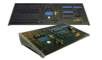
5 Introduction The JesterML The JesterML lighting desks are compact user-friendly memory desks which record channel levels and fixture information, and provide both theatre style sequential memory access and sub-master style access, as well as colour, beamshape and position palettes. Memories and Submasters can be recorded as scenes or sequences (chases). Crossfade times and chase speed, direction and attack can be adjusted as required. The JesterML can control 48 generic (dimmer) control channels, plus 30 intelligent fixtures (moving lights). Regardless which particular JesterML desk you are using, all 48 dimmer channels can be controlled by connecting another desk (wing) to the DMX Input. The output from the desk is by DMX512-A only Issue of 73
.")

6 Introduction Master Controls and Displays These controls set the general operating conditions for the desk. MODE The MODE button is used to select the operational mode of the desk. The red LEDs to the left of the button show the current operating mode (SETUP, PRESET, PROGRAM, RUN). GRAND MASTER The GRAND MASTER fader is used for overall control of the maximum output levels from all brightness channels of the desk. BLACKOUT The BLACKOUT button makes all the brightness channels output zero. Pressing the BLACKOUT button toggles between Blackout (all channels at zero) and normal desk outputs. The LED in the BLACKOUT button indicates the current state (Flashing = 6 of Issue 2.0
7 Introduction Blackout, Off = Normal). This is also replicated on the monitor, with flashing BLACKOUT text on the screen. Both Blackout and the Grand Master do not affect LTP (fixture attribute) channels or channels grabbed from the DMX-input. PROGRAM/GO The PROGRAM/GO button is a multi-coloured, multi-function button which adapts to the mode in which the desk is currently set. In Preset Mode, the button is inactive although when set to wide mode, it functions as a preset store button, and is coloured yellow. In Program Mode, the PROGRAM/GO button functions as a program (record) button, and is coloured red. In Run mode, the PROGRAM/GO button acts as a go/pause button and is coloured green. Turning on the Desk 1. Connect the DMX cable and monitor (if required). Although the monitor is optional, you will find the desk easier to use with a monitor attached. 2. Connect the power supply to the desk and switch it on at the mains. 3. Ensure that Blackout is not active (the red LED in the Blackout button is off). 4. Set the A MASTER and B MASTER faders to zero. 5. Set the GRAND MASTER fader to full. Numeric Entry Numeric fields can be completed by using the Multi-Function-Keys. Firstly navigate to the required field, then press ENTER. The Multi-Function-Keys now function as number buttons. Once the number is entered, press ENTER to confirm. If preferred, the Preset B Flash buttons on the JesterML24 and JesterML48 can also be used for numeric entry when the Multi-Function-Keys are displaying number buttons. A USB keyboard can also be connected to speed up entering names and numbers. Note that due to internal resource limitations, the USB Keyboard will not operate when MIDI is enabled, or when in the Setup menus which require access to a USB Memory Stick (e.g. Load/Save) Issue of 73
8 Preset Mode Preset Mode PRESET Mode allows direct control of the fixtures, replay of palettes, and control of the 48 preset channels. Whichever desk you are using, you can connect another desk (wing) - e.g. a Jester24/48 to the DMX Input to control the preset channels. See the section on DMX Input for further details. The operation is almost identical whether the faders and buttons are on the desk itself, or on a wing. When the desk is in PRESET Mode all the memory functions are disabled, offering a completely manual control system. The desk can be operated in either two-preset, or single-preset mode. In Two Preset operation, separate scenes are set up on PRESET A and PRESET B using the individual channel faders. The A MASTER and B MASTER faders are used to crossfade between the two scenes. By pressing PAGE B, wide mode is selected, indicated by the lower LED next to the PAGE B button being lit. In wide mode, it is still possible to crossfade between two scenes. The first scene is set up on the PRESET A and PRESET B faders and is stored in the desk temporarily using the yellow PROGRAM/GO (Store) button. Once stored, another scene can be set up on the PRESET A and PRESET B faders. The A MASTER and B MASTER faders are used to crossfade between the stored scene and the scene on the PRESET faders. Crossfades between scenes can be manual or timed. As with all operating modes of the desk, overall output of the brightness channels is under the control of the GRAND MASTER. PRESETS A AND B In two-preset mode, the PRESET A and PRESET B faders both control the same set of channels. In single-preset mode (wide mode), the PRESET A faders control the first half of the channels, and the PRESET B faders control the second half of the channels. CHANNEL FLASH BUTTONS Each fader has a CHANNEL FLASH button, which is used to flash individual channels. By selecting SPECIAL, these buttons can be disabled, or switched to SOLO mode (note that SOLO mode does not apply to FLASH buttons on a wing). A MASTER AND B MASTER In two preset mode, the A MASTER controls the output level from the PRESET A faders and the B MASTER controls the output level from the PRESET B faders. In wide mode, the A MASTER and B MASTER faders control the output level from both the PRESET A and PRESET B faders, and the stored scene. The B MASTER is reversed (100% at the bottom of its travel) to facilitate manual crossfades when moving the A MASTER and B MASTER in tandem. FADE TIME The fade time is set using the wheels when SPECIAL is selected, and determines the fade time when crossfading between scenes. The control can be set to Manual or to a time between 0.1 second and 5 minutes. This time is indicated on the LCD above the wheels. The PROGRAM/GO button (used as a STORE button will blink yellow when a timed crossfade is taking place. PROGRAM/GO The PROGRAM/GO button is used in wide mode as a STORE button. This button is used to control which master (A MASTER or B MASTER) has control of the PRESET faders, and which master has control of the stored scene. The Main LCD indicates the current state (A FADERS, B STORED or B FADERS, A STORED). 8 of Issue 2.0
9 Preset Mode Two Preset Operation In two preset operation the PRESET A and PRESET B faders, the A MASTER and B MASTER and the GRAND MASTER are used to control the output levels from the desk. The fade time set with the middle wheel when SPECIAL is selected, is used to determine the crossfade time between the preset masters. Setting up for Two Preset Operation 1. If the desk is not already in PRESET Mode, press and hold the MODE button for 1 second. The PRESET LED next to the MODE button will come on. 2. Ensure the upper LED next to the PAGE B button is lit, and the fade time (press SPECIAL and use the middle wheel) is set to Manual. To Output a Scene from Preset A 1. Set the required levels for each channel on the PRESET A faders. 2. Set the A MASTER to full. The scene set up on PRESET A is output live. To Output a Scene from Preset B 1. Check that the B MASTER is set to Set the required levels for each channel on the PRESET B faders. This action is performed without the output levels of the desk changing. 3. Set the B MASTER to full. The scene set up on PRESET B is output live, mixed with the scene on PRESET A. 4. To remove the scene on PRESET A, bring the A MASTER to zero. Manual Fading between Scenes 1. Ensure that the fade time (press SPECIAL and use the middle wheel) is set to Snap. 2. Set up a scene using the PRESET A faders. 3. Set the A MASTER to full, and the B MASTER to zero. The scene set on the PRESET A faders will be output. 4. Set up a different scene on the PRESET B faders. This is done blind, without the output levels changing. 5. To crossfade to the new scene set up on PRESET B, simultaneously move the A MASTER to zero and the B MASTER to full. You have direct control over the speed of the crossfade. As the master faders are moved in tandem the scene setup on PRESET B will fade in and the scene set on PRESET A will fade out. This crossfade is dipless. 6. A new scene can then be set up on PRESET A without affecting the outputs. 7. To crossfade to the new scene on PRESET A, simultaneously move the A MASTER to full and the B MASTER to zero. 8. As the A and B master faders are moved in tandem the scene set up on PRESET B will fade out and the new scene set on PRESET A will fade in. The crossfade is dipless Issue of 73
10 Preset Mode Timed Crossfades between Scenes 1. Set the A MASTER and B MASTER to zero. 2. Set up a scene using the PRESET A faders. 3. Set up a different scene on the PRESET B faders. 4. Set the fade time required to fade scene A in, by pressing SPECIAL and moving the middle wheel. 5. Quickly move the A MASTER to full. The scene on the PRESET A faders will fade in and be output live. (The time taken for the fade to complete is determined by the fade time setting). 6. The STORE button will blink yellow while the dipless crossfade is taking place. 7. To crossfade to the scene on PRESET B, quickly move the A MASTER to zero and the B MASTER to full. The scene on PRESET B will fade in and the scene on PRESET A will fade out in the set fade time. The STORE button will blink yellow while during the crossfade. 8. A new scene can then be set up on PRESET A without affecting the outputs. 9. To crossfade to the scene on PRESET A, quickly move the A MASTER to full and the B MASTER to zero. The scene on PRESET A will fade in and the scene on PRESET B will fade out in the set fade time. The STORE button will blink yellow while the dipless crossfade is taking place. Flashing Channels Two Preset Mode 1. Ensure that the Flash function is active this is set using the Multi-Function-Keys when SPECIAL is selected. 2. Press and hold an individual CHANNEL FLASH button. (Those below the PRESET A faders or PRESET B faders can be used). The channel is then added to the scene at the level set on the GRAND MASTER. 3. Release the CHANNEL FLASH button. The channel returns to its previous (fader) level. FLASH: The selected channels will be sent to full when the button is pressed, and will be returned to its fader level when the button is released. No other channels are affected. SOLO: The selected channels will be sent to full and all other brightness channels will be sent to blackout. When the button is released, all brightness channels are returned to their normal levels. NOTES Flash buttons on a wing The flash mode not apply to FLASH buttons on a wing. 10 of Issue 2.0
11 Preset Mode Wide Mode When operating in Wide Mode, you are able to crossfade between or combine two scenes which use all the faders on the desk. A scene is set up using the PRESET A and PRESET B faders. The PRESET A faders control the first half of the channels whilst the PRESET B faders control the second half of the channels. This scene is then stored temporarily by pressing the PROGRAM/GO (STORE) button. A second scene can then be set up on the PRESET A and PRESET B faders. The A MASTER and B MASTER faders can then be used to crossfade between the two scenes. The PROGRAM/GO button is used to control which master has control of the PRESET channel faders, and which the stored scene. The GRAND MASTER is used to control the final output levels from the desk. The fade time set when SPECIAL is selected is used to determine the crossfade time between the two scenes. Setting up for Wide Operation 1. If the desk is not already in PRESET Mode, press and hold the MODE button for 1 second. The PRESET LED next to the MODE button will come on. 2. Activate Wide Mode. To do this, ensure that the lower LED next to the PAGE B button is lit. On first invoking wide, the PRESET faders will be assigned to the A MASTER, and the stored scene assigned to the B MASTER. The Main LCD will indicate this (A FADERS, B STORED). The temporarily stored scene will be cleared. Storing and Cross Fading Scenes 1. Set the A MASTER and GRAND MASTER to full and the B MASTER to zero. Press SPECIAL and set the fade time to Snap using the middle wheel. 2. Ensure that the Main LCD indicates A FADERS, B STORED (if there is no indication on the Main LCD, you re not in Wide mode, and if the Main LCD indicates B FADERS, A STORED, press the PROGRAM/GO button) 3. Set up a scene using the PRESET A and PRESET B faders. This scene will be output. 4. To store the scene press the PROGRAM/GO button, which in preset mode is coloured yellow to indicate its function as STORE. The fader levels are temporarily stored and the Main LCD will change to indicate B FADERS, A STORED. The A MASTER is now assigned to the stored scene and the B MASTER assigned to the faders, so the outputs remain the same. 5. Set up the next scene using the PRESET A and PRESET B faders. (The outputs are not affected since the B MASTER is currently at zero). 6. To crossfade between the stored scene and the scene on the PRESET faders, simultaneously move the A MASTER to zero and the B MASTER to full. A dipless crossfade will occur. 7. If the PROGRAM/GO button is pressed again, the output levels are saved into the temporary store (overwriting the previous values) and the Main LCD will change to indicate A FADERS, B STORED. The B MASTER is now assigned to the stored scene and the A MASTER assigned to the PRESET faders, so the outputs remain the same Issue of 73
12 Preset Mode 8. The operations described in steps 5-8 can then be repeated to set up a new scene on the faders, crossfade to the new scene, and save it to a temporary store etc. Manual and Timed Crossfades Crossfading between the scene set up on the PRESETS and the stored scene is achieved by moving the A MASTER and B MASTER faders in tandem. If the fade time set when SPECIAL is selected is set to Snap, the crossfade time is determined by the speed at which the A MASTER and B MASTER faders are moved. You have direct control over the speed of the crossfade. The crossfade time can be changed from 0.1 seconds and 5 minutes using the middle wheel when SPECIAL is selected. Flashing Channels - Wide mode 1. Ensure that the Flash function is active this is set using the Multi-Function-Keys when SPECIAL is selected. 2. Press and hold an individual CHANNEL FLASH button. The buttons below the PRESET A faders control the first half of the channels, those below the PRESET B faders control the second half of the channels. The corresponding channel is then added to the scene at the level set on the GRAND MASTER. Dependant on the flash mode, the other channels may or may not be affected see below. 3. Release the CHANNEL FLASH button. All channels return to their previous level. FLASH: The selected channels will be sent to full when the button is pressed, and will be returned to its fader level when the button is released. No other channels are affected. SOLO: The selected channels will be sent to full and all other brightness channels will be sent to blackout. When the button is released, all brightness channels are returned to their normal levels. NOTES Stored Scene Any stored scene being output in PRESET Mode will be removed from the outputs if the desk is changed to PROGRAM, RUN or SETUP Modes. Flash buttons on a wing The flash mode not apply to FLASH buttons on a wing. 12 of Issue 2.0
13 Program Mode Program Mode Introduction Program Mode on the desk is used to select and create new memories or submasters and enter moving light data into Palettes. Once an item has been created it can be modified within Program Mode, and the contents re-stored. Memory Types There are two memory types which can be programmed on the JesterML desk. They are SCENE memories and CHASE memories. A SCENE memory consists of a single static state, recording the output look. A CHASE memory consists of a number of steps (maximum of 999). Each step consists of a single static state, recording the output look. The up or down cursor buttons are used to select the required memory, whilst the Main LCD displays the <Mem:> field. The Main LCD shows the selected memory number, along with its associated fade time(s) and its name. If the memory being programmed is a CHASE, the Main LCD also shows the current step number. The fixture controls and PRESET faders are used to set the output look and the PROGRAM/GO button used to save the look to memory. Submaster Types Scenes and Chases can also be recorded onto Submaster faders. These faders allow you to fade in scenes or chases on a single fader, whilst in Run mode. Pressing a Channel Flash button whilst in Program Mode allows you to select the required submaster for programming. Submasters can also be selected by pressing PAGE B, and then using the Multi-Function-Keys. The JesterML has 20 pages of 24 submasters, totalling 480. The operation of the Channel Flash buttons is as follows: JesterML JesterML24 JesterML48 Preset A Not available use Subs 1-12 Subs 1-24 Preset B Multi-Function-Keys Subs Subs 1-24 When programming submasters, it is important to remember which ones on each page will be accessible on faders in Run Mode: JesterML JesterML24 JesterML48 See DMX Input Wing Width in SETUP Press PAGE B to put the Multi-Function-Keys into Submasters mode and select the current page. The Page Up, Page Down and 7-segment display by the Multi- Function-Keys select the submaster page (1 to 20). The current submaster page is displayed on the external monitor at all times. Low Memory Warning The JesterML has a maximum capacity of 500 memories, plus 480 submasters, plus 30 each of Colour, Beamshape and Position palettes. Each memory may be a SCENE or a CHASE. The number of CHASE steps, or a large number of fixture Issue of 73
14 Program Mode channels in use, may cause the total number of memories to be less than 500. The desk software monitors the amount of memory used and displays a warning when the memory available is getting low, and when there is none left. NOTES Tagging By default, all fixture intensities and preset channels are recorded into every memory or submaster, and are mixed on a highest-takes-precedence (HTP) basis when replayed. Fixture parameters (LTP channels) are only recorded if they are tagged. This behaviour can be changed in Setup (Record Options) if required. It is very important to consider what is tagged when working with moving lights. Further details are given in the section on Fixture Control, which it is recommended that you read fully. Program Controls and Displays PRESET A AND PRESET B The PRESET A faders control the first half of the channels. The PRESET B faders control the second half of the channels. CHANNEL FLASH BUTTONS Each of the PRESET faders has a corresponding CHANNEL FLASH button. They are used to select a submaster for editing. By pressing PAGE B, the Multi-Function-Keys can also be used to select submasters. A MASTER and B MASTER The A and B MASTER faders are disabled in PROGRAM mode. Main LCD The Main LCD indicates the selected memory, submaster or palette number and the current step number (if applicable). An asterix (*) after the number indicates that the item is unprogrammed, whilst a plus (+) indicates the memory or submaster includes captured DMX data from the DMX-in port. DMX-Input data is not recorded into palettes. MONITOR The monitor displays the selected memory or submaster with a yellow bar and the current step number, in the steps column. An asterix (*) after a number indicates that the item is unprogrammed. Names for both submasters and memories are displayed on the monitor output, as are the fade up & down times for a memory, and the output levels. CLEAR This button is used to clear a memory, submaster or palette, or to clear a step from a chase memory/submaster. Hold the button for 1 second to delete a scene, step or palette, hold for 1s with SHIFT to delete a chase, and tap to backspace when entering names. PROGRAM/GO In Program Mode, this button is used to save the output levels and fade times into the selected memory or submaster (no fade times are stored for submasters or palettes). If the memory or submaster is a chase, the output levels are saved into the current step and the chase modifiers are stored for the entire chase. EDIT This button loads the currently selected item onto the outputs. If it is a chase, then the chase is run. When EDIT is active, the LED in the button is lit. To save changes back to the original location, simply 14 of Issue 2.0
15 Program Mode press the button again, and the LED will go out. To save changes to a new location, first select that location using: Memory: cursor buttons Submaster: Flash buttons, or PAGE B then Multi-Function-Keys Palette: COLOUR, BEAMSHAPE or POSITION then Multi-Function-Keys then press PROGRAM/GO to store to the new location. Again the LED will go out as the desk is no longer in edit mode. This provides a Copy function. The EDIT button also works in RUN Mode, so that quick edits can be made to the selected memory/submaster, with the desk returning automatically to RUN Mode once the edit is complete Issue of 73
16 Program Mode Setting up the Desk for Programming 1. If the desk is in RUN Mode, press the MODE button to switch to PROGRAM Mode. If the desk is in any other mode, press and hold the MODE button for 1 second to enter PROGRAM Mode. The red LEDs next to the MODE button indicate the current mode. 2. Set all the PRESET faders to zero 3. Set the GRAND MASTER to full and ensure that blackout is not active (LED in the BLACKOUT button is off). NOTES Editing Live When changing from RUN Mode to PROGRAM Mode, it is the NEXT memory which will be selected for editing. To make an edit to the current memory without sudden output changes, simply set the NEXT memory to the same as the CURRENT memory, before changing from RUN Mode to PROGRAM Mode. Selecting a Memory Number The Main LCD shows the selected memory number <Mem: #>. This is replicated on the monitor by the selection having a yellow bar. An unprogrammed memory has an asterix (*) after the memory number. An unprogrammed memory is always a scene memory, but can be converted to a chase easily. The up or down cursor buttons are used to select the required memory number to program. Scene Memories Programming a New Scene Memory 1. Set up the desk for programming as described above. 2. Use the up or down cursor buttons to select an unprogrammed memory. 3. Use the fixture controls and PRESET faders to set the required look. 4. Press SPECIAL and set the required fade time using the wheels. 5. Press the PROGRAM/GO button. The output levels and fade times are now stored in the selected memory. If the next memory in the stack is unprogrammed, the Main LCD and monitor will now select it, ready for programming. The outputs remain unaltered. Programming a New Scene Submaster 1. Set up the desk for programming as described above. 2. Press the CHANNEL FLASH button below a submaster you wish to program. You can also press PAGE B and use the Multi-Function-Keys to select a submaster. 3. Use the fixture controls and PRESET faders to set the required look. 4. Press the PROGRAM/GO button. The output levels are now stored in the selected submaster. The outputs remain unaltered. NOTES Tagging 16 of Issue 2.0
17 Program Mode After programming a new scene memory or submaster, the JesterML will automatically clear the tag states ready for you to start programming the next item. Split Fade Times Sometimes you may wish a scene to have different up and down fade times. The JesterML allows you to define these times using the wheels. 1. Select the memory you wish to alter the fade times of. 2. Select SPECIAL. The fade times will be shown on the LCD above the wheels, and also on the Main LCD and monitor. 3. Use the first finger wheel to set the Fade Up time, and the second finger wheel to set the Fade Down time. The thumb wheel can be used to edit both times together. If both times are equal, or no split time has been defined, no down time is shown on the Main LCD and monitor. 4. Overwrite the memory. To do this, press and hold the PROGRAM/GO button for 1 second. See note on page 18 for more information on overwriting memories. Overwriting a Programmed Scene 1. Set up the desk for programming as described above. 2. Use the up or down cursor buttons to select a programmed memory. 3. Press EDIT to output the selected memory, if required. The LED in the EDIT button will come on. 4. Use the fixture controls and PRESET faders to set the required look. If a channel is higher than the current fader level, push the fader up to grab the level, then pull it down to the required level. Channel levels are displayed at the bottom of the monitor output. 5. To save the edits back to the original memory, press the EDIT button again. The outputs remain unaltered. 6. To save the edits to a different location, select that location using: Memory: cursor buttons Submaster: Flash buttons, or PAGE B then Multi-Function-Keys Palette: COLOUR, BEAMSHAPE or POSITION then Multi-Function-Keys Then press the PROGRAM/GO button if the selected item is already programmed, the Main LCD asks you if you wish to overwrite it. Press the PROGRAM/GO button again, or hit ENTER. The new levels are now stored in the selected location. The original contents of that location are overwritten. The outputs remain unaltered. Overwriting a Programmed Submaster 1. Set up the desk for programming as described above. 2. Press the CHANNEL FLASH button below the submaster you wish to overwrite. You can also press PAGE B and use the Multi-Function-Keys to select a submaster. 3. Press EDIT to output the selected submaster, if required. The LED in the EDIT button will come on. 4. Use the fixture controls and PRESET faders to set the required look. If a channel is higher than the current fader level, push the fader up to grab the level, then pull it down to the required level. Channel levels are displayed at the bottom of the monitor output Issue of 73
18 Program Mode 5. To save the edits back to the original submaster, press the EDIT button again. The outputs remain unaltered. 6. To save the edits to a different location, select that location using: Memory: cursor buttons Submaster: Flash buttons, or PAGE B then Multi-Function-Keys Palette: COLOUR, BEAMSHAPE or POSITION then Multi-Function-Keys Then press the PROGRAM/GO button if the selected item is already programmed, the Main LCD asks you if you wish to overwrite it. Press the PROGRAM/GO button again, or hit ENTER. The new levels are now stored in the selected location. The original contents of that location are overwritten. The outputs remain unaltered. Editing Channel Levels in a Scene If you wish to make changes to a scene memory or submaster, the easiest way is to follow these simple steps. 1. Select the item to be edited using: Memory: cursor buttons Submaster: Flash buttons, or PAGE B then Multi-Function-Keys Press the EDIT button to output the selected scene. 2. Use the fixture controls and PRESET faders to set the required look. To gain control of a channel you will need to push the fader up above the level of the channel in the scene, to grab the channel, then move it to its new value. 3. Once you have made all the required edits, press the PROGRAM/GO button. The Main LCD and monitor will ask you to confirm whether you d like to overwrite the memory or make the memory into a chase. Select <Overwrite> and press ENTER. NOTES Overwriting The JesterML has four methods of overwriting a memory: - Press PROGRAM, then press ENTER at the prompt. - Press PROGRAM, then press PROGRAM again at the prompt. - Hold PROGRAM for a few seconds. - Press SHIFT and PROGRAM together. Deleting a Scene Memory 1. Use the cursor buttons to select the programmed memory you wish to clear. 2. Hold the CLEAR button for 1 second. The memory will be cleared and the asterix (*) will appear next to the memory number in the Main LCD to indicate that the memory is now unprogrammed. Deleting a Scene Submaster 1. Press the CHANNEL FLASH button under the Submaster you wish to clear. You can also press PAGE B and use the Multi-Function-Keys to select a submaster. 2. Hold the CLEAR button for 1 second. The Submaster will be cleared and the asterix (*) will appear next to the submaster number in the Main LCD to indicate that the submaster is now unprogrammed.. 18 of Issue 2.0
19 Program Mode Deleting a Palette 1. Use the Multi-Function-Keys to select the programmed palette you wish to clear. If you don t want the palette to be played when it is selected, first ensure that no fixtures are selected. 2. Hold the CLEAR button for 1 second. The palette will be cleared, and the asterix (*) will appear next to the palette number in the Main LCD to indicate that the palette is now unprogrammed Issue of 73
20 Program Mode Chase Memories Programming a New Chase 1. Set up the desk for programming as described above. 2. Select an unprogrammed item using: Memory: cursor buttons Submaster: Flash buttons, or PAGE B then Multi-Function-Keys 3. Use the fixture controls and PRESET faders to set the required output levels for the step. The output will appear live. 4. Press the PROGRAM/GO button. The output levels are stored as the first step of the chase. You will now have to reselect the memory (the submaster will stay selected). Use the up or down cursor buttons to select the memory you wish to make into a chase. 5. Use the fixture controls and PRESET faders to set the required output levels for the next step. The output will appear live. 6. Press the PROGRAM/GO button to save the current output levels. The first time you do this, the Main LCD will ask you if you wish to overwrite the existing memory, convert the memory to a chase, or cancel the operation. Use the cursor buttons to select the <Make Chase> option, and press ENTER. The current outputs will be stored as step2, and the desk will increment to show step3 as the next available step. 7. Repeat steps 5 and 6 until all steps in the Chase have been programmed. 8. Press the left cursor button to move away from the <Step> field, and back to the memory/submaster number. 9. Press EDIT and the chase will start to run sequentially. Ensure CHASES is selected, and adjust the speed by using the middle wheel. If required, you can also adjust the following using the Multi-Function-Keys: Direction: Forwards, Backwards, Bounce or Random Brightness Attack: Snap, Ramp Down, Ramp Up, or CrossFade Colour/Beamshape/Position Attack: Snap or Fade NOTES Tagging and Chases All steps of a chase must have the same Tag states when programming in Partial Mode. To ensure this, the tags from the most recently programmed step (regardless of it s position in the chase) are used for the entire chase. The JesterML automatically clears the tag states after programming a scene memory. When <Make Chase> is selected, the JesterML merges the tag states from the scene (Step 1) with the new tag states (Step 2). The JesterML does not automatically clear the tag states when you program subsequent steps. Naming Memories, Submasters & Palettes Memories, Submaster & Palettes can all be named. To add a name, first select the item required, then move to the Name field (indicated as < > on the Main LCD) and press ENTER. The JesterML enters Name Mode. When naming items, the Multi-Function-Keys become letter entry keys, using multiple presses to select 20 of Issue 2.0
21 Program Mode between groups of letters. You can also use the cursor up or down buttons to alter the letter of the selected character, and the cursor left and right buttons to select different characters. If preferred, the Preset B Flash buttons on the JesterML24 and JesterML48 can also be used for name entry when the Multi-Function-Keys are displaying letters. To enter a capital letter, press SHIFT with the button required. When you have finished entering the name, press ENTER to confirm. 1, 1 2 a b c 2 3 d e f 3 4 g h i 4 5 j k l 5 6 m n o 6 7 p q r s 7 8 t u v 8 9 w x y z 9 10 _ 0 11 ( ) ! # A USB keyboard can also be connected to speed up entering names and numbers. Note that due to internal resource limitations, the USB Keyboard will not operate when MIDI is enabled, or when in the Setup menus which require access to a USB Memory Stick (e.g. Load/Save). Inserting Memories 1. Use the up or down cursor buttons to select the required memory (if you wish to insert 3.5, select memory 3). 2. Press the INSERT button. 3. Use the up or down cursor buttons to navigate to the required memory number. All memories between 3.1 and 3.9 will be available. The Main LCD shows the memory number with an asterix (*), indicating that it is unprogrammed. 3. Use the fixture controls and PRESET faders to set the required output levels for the new step. The output will appear live. 4. Press the PROGRAM/GO button to save the output levels and fade time(s) into the new memory. The asterix disappears from the Main LCD, and the next memory is selected. Inserting a Step 1. Use the up or down cursor buttons to select the required chase memory. 2. Press the right cursor button to select the step field. 3. Use the cursor up or down buttons to select the step before the one you wish to insert, (eg, to insert a step between steps 4 and 5, select step 4). 4. Press the INSERT button. The Main LCD shows the inserted step number with an asterix (*), indicating that it is unprogrammed. 5. Use the fixture controls and PRESET faders to set the required output levels for the new step. The output will appear live. 6. Press the PROGRAM/GO button to save the output levels into the new step. The asterix disappears from the Main LCD. Deleting a Step 1. Use the up or down cursor buttons to select the required chase memory. 2. Press the right cursor button to select the step field. 3. Use the cursor up or down buttons to select the step to be deleted. 4. Hold the CLEAR button for 1 second. The selected step will be removed from the chase. The Main LCD will show the previous step number Issue of 73
22 Program Mode Overwriting a Step 1. Use the up or down cursor buttons to select the required chase memory. 2. Press the right cursor button to select the Step field. 3. Use the cursor up or down buttons to select the step to overwrite. 4. Press the EDIT button if you wish to load the existing contents of the step. The LED in the EDIT button will come on. 5. Use the fixture controls and PRESET faders to set the required output levels. The output is live. 6. If you used the EDIT button to load the existing step, press it again to save the changes, and the LED in the EDIT button will go out. Otherwise press the PROGRAM/GO button to save the changes. The Main LCD asks you if you wish to overwrite the step, select <Overwrite> and press ENTER. Overwrite can be forced by holding the PROGRAM/GO button or by using SHIFT+PROGRAM/GO. NOTES Adding Steps A new step cannot be added until the current step has been saved by pressing PROGRAM/GO Renumbering Steps Any original steps in a Chase after an inserted step will be renumbered accordingly. For example, if you started with a 10 step Chase and added a step between steps 4 and 5, the new step becomes step 5 and the original steps 5-10 become steps Any steps in a Chase after a deleted step will be renumbered accordingly. For example, if you start with a 10 step Chase and delete step 5, original steps 6 10 become steps 5-9. Inserting Steps The INSERT button can only insert a step after the current step. If you wish to insert a step before Step 1 of a Chase then following actions must be performed: Select Step 1 and press the EDIT button. Insert a new step after Step 1 using the INSERT button. Press the PROGRAM button to save the contents of Step 1 to the new Step 2. Set up the new look for Step 1, and re-program it using the PROGRAM button. Deleting Last Step If there is only one step in the chase, it will be automatically converted to a scene memory. The last step should be deleted in the same way you would delete a normal scene. Maximum Steps Programmed If an attempt is made to insert a step into the Chase when the maximum 999 steps have been programmed, the Main LCD displays a warning. The chase and outputs are unaffected. Deleting a Chase Memory 1. Use the cursor up or down buttons to select the chase memory to be deleted. 2. Press and hold SHIFT with the CLEAR button for 1 second. The memory will change to an unprogrammed scene memory. Deleting a Chase Submaster 22 of Issue 2.0
23 Program Mode 1. Press the CHANNEL FLASH button under the Submaster you wish to clear. You can also press PAGE B and use the Multi-Function-Keys to select a submaster. 2. Press and hold SHIFT with the CLEAR button for 1 second. The Submaster will be cleared. NOTES Viewing Steps It is possible to scroll through the steps of a chase memory or submaster, using the cursor up or down buttons when the Step field is selected. Steps are output by pressing the EDIT button. DMX Input The JesterML allows you to input a full universe of DMX and capture this to any memory or submaster, allowing the JesterML to act as a backup console. When a DMX input is attached to the desk, the JesterML automatically re-transmits any unpatched channels on the DMX output. Channels which are patched to the Preset Faders are mixed highest-takes-precedence. Channels which are patched to the Fixtures are ignored for this reason it is recommended that when using as a backup console, that no fixtures are patched. When a memory (or submaster) is recorded with a DMX-input present, the memory (or submaster) will store all 512 channels, including any unpatched channels. The memory or submaster will show a +, to indicate the additional data has been stored. This will then act as a backup memory or submaster, allowing you to replicate the scene at any required time. DMX-In channels do not crossfade their outputs and instead trigger when the memory or submaster is triggered. DMX-Input is not recorded into palettes. When a DMX Input Wing Width is set in Setup, the DMX Input operates in Wing Mode, and additional channels are not recorded into memories and submasters. In this case, the +DMXin indication on the monitor screen will be replaced with +WingNN, where NN is the wing width. See the section on DMX Input for further details Issue of 73
24 Run Mode Run Mode Introduction Run Mode on the desk is used to replay the previously recorded memories, submasters, and palettes. The programmed memories are stored in a stack and can be replayed one at a time in ascending numerical order. This allows the complete show to be replayed in order, simply by pressing the PROGRAM/GO button. The cursor buttons can also be used to select a particular memory, which can then be output by pressing the PROGRAM/GO button. The Main LCD shows the current and next memory to be output. The crossfade time, chase speed and attack can be adjusted using the various front panel controls. The brightness output levels are determined by the programmed levels in the memory, the MEMORY MASTER and the GRAND MASTER. The brightness levels in a Submaster are controlled directly by the submaster and the GRAND MASTER fixture parameter (LTP) channels are triggered when the submaster fader is raised above 5%. All 24 submasters may be controlled from the faders on a wing see the section on DMX Input for further details. Run Mode Controls and Displays PRESET A AND PRESET B The PRESET A faders control the first or second half of the channels, depending on the PAGE A setting. The PRESET B faders control submasters. CHANNEL FLASH BUTTONS The PRESET A flash buttons are used to flash the first or second half of the channels, depending on the PAGE A setting. The PRESET B flash buttons are used to flash the corresponding submaster, depending on the current page. By pressing PAGE B, the Multi-Function-Keys can also be used to flash submasters. By selecting SPECIAL, these buttons can be disabled, or switched to SOLO mode. Note that SOLO mode does not apply to FLASH buttons on a wing. A MASTER AND B MASTER The A MASTER is used to control the maximum output level from the PRESET A faders. The B MASTER fader is inactive in RUN mode. MEMORY MASTER The MEMORY MASTER fader is used to control the output level of the brightness channels in the current memory in the stack. FADE TIME The fade time setting (set using the wheels when SPECIAL is selected) is used for several things in RUN Mode: To determine the rate at which the current memory will fade out and next memory fade in when the PROGRAM/GO button is pressed, and to determine the fade time of submaster faders and the PRESET A master. Palettes are replayed instantly (Snap) without a fade time. Main LCD The Main LCD shows details of the current and next memory to be output. If a submaster is selected then the name of that submaster will be displayed. 24 of Issue 2.0
25 Run Mode MONITOR The monitor shows details of the current and next memories, as well as all submasters. SPEED The speed setting (set using the wheels when CHASES is selected) is used to adjust the speed of all currently active chases. A relative adjustment is made to each chase. If Manual is selected on the speed, then the INSERT button is used to step chases on the memory stack. If the Flash Mode (set using the Multi-Function-Keys when SPECIAL is selected) is set to Go, then the submaster flash buttons can be used to step chases on submasters. By pressing PAGE B, the Multi-Function-Keys can also be used for submasters in this way. If the SHIFT button is held down when the speed is adjusted, then only the selected chase is affected. DIRECTION The direction options (set using the Multi-Function-Keys when CHASES is selected) can be used to override the direction of all currently active chases. If the SHIFT button is held down when the direction is adjusted, then only the selected chase is affected. ATTACK The attack options (set using the Multi-Function-Keys when CHASES is selected) can be used to override the attack options of all currently active chases. If the SHIFT button is held down when the attack options are adjusted, then only the selected chase is adjusted. PROGRAM/GO The PROGRAM/GO button is used to initiate a crossfade between the memory currently being output and the next memory as indicated by the Main LCD. Pressing the PROGRAM/GO button automatically increments the memory number in the Main LCD, and the selection on the monitor. Pressing PROGRAM/GO with SHIFT held down acts as a PAUSE button, stopping the crossfade which is currently active. The crossfade can then be restarted by pressing the PROGRAM/GO button again. The PROGRAM/GO button is normally illuminated green in Run Mode. When a crossfade is paused, it flashes green. While a crossfade is in progress, it blinks from green to yellow. EDIT The EDIT button also works in RUN Mode, to allow the selected memory/submaster to be quickly edited. When pressed, the desk will temporarily change to PROGRAM Mode. Once edits have been saved, the desk will automatically return to RUN Mode. NOTES Remote Go Pressing a switch connected to the Remote Input jack socket on the back panel has the same effect as pressing the PROGRAM/GO button, by default. This can be altered in SETUP. Entering Run Mode 1. If the desk is in PRESET Mode or SETUP Mode, press and hold the MODE button for 1 second. The desk will change to PROGRAM Mode. When the desk is in PROGRAM Mode press the MODE button to enter RUN Mode. 2. Set all the PRESET faders to zero. 3. Set the A MASTER and B MASTER to zero, and set the MEMORY MASTER to full Issue of 73
26 Run Mode 4. Set the GRAND MASTER to full and ensure that blackout is not active (the LED in the BLACKOUT button is off). NOTES Editing Live When changing from RUN Mode to PROGRAM Mode, it is the NEXT memory which will be selected for editing. To make an edit to the current memory without sudden output changes, simply set the NEXT memory to the same as the CURRENT memory, before changing from RUN Mode to PROGRAM Mode. Selecting the Next Memory The Main LCD and monitor both display data about the current and next memories. The cursor up or down buttons are used to select the next memory to be output. Pressing the cursor down button will take you to the next programmed memory. When the last programmed memory is reached, pressing the cursor down button will take you to the first programmed memory. Pressing the cursor up button will take you to the previous programmed memory. When the first programmed memory is reached, pressing the cursor up button will take you to the last programmed memory. Pressing cursor up and cursor down together will select the first programmed memory. To Determine the Current Memory The Main LCD display shows the current memory number in the left hand side of the display <C: #>. This is also shown on the monitor, highlighted with a green bar. Outputting a Programmed Memory The cursor up or down buttons are used to select the next memory to be output. The PROGRAM/GO button is used in Run Mode as the GO button, which will initiate a dipless crossfade between the current memory and the next memory. The Main LCD automatically selects the next programmed memory, and changes the current (C:) memory to the one which is now being output. The crossfade takes its time from the programmed Fade times for the incoming cue. This crossfade times can be manually overridden by selecting SPECIAL and adjusting with the wheels. Pausing a Crossfade 1. Use the cursor buttons to select the next memory to be output. 2. Press the PROGRAM/GO button. This initiates a crossfade to the selected memory, in the time defined by the memory. While the crossfade is taking place, the PROGRAM/GO button blinks from green to yellow. 3. To pause the crossfade, press and hold the SHIFT button and press the PROGRAM/GO button. The PROGRAM/GO button will flash green and the outputs remain static. 5. To restart the crossfade, press the PROGRAM/GO button again. The crossfade continues, with the PROGRAM/GO button blinking from green to yellow. When the crossfade is complete, the PROGRAM/GO button will illuminate green. NOTES Selecting Memories 26 of Issue 2.0
27 Run Mode Only programmed memories are selectable. ignored. Any unprogrammed memories are Presets in Run Mode When in Run Mode, the preset faders (Preset A) function as highest takes precedence (HTP) channels. Each channel can be increased in brightness by raising its appropriate fader (remember that Preset A will be controlled overall by the A MASTER). The channels can also be flashed, using the Flash Mode set under SPECIAL. As the desk has two pages of channels, the PAGE A button is used to switch between the two pages. When you switch to a new page of channels, all the faders reset in software to the level of the presets on that page. In order to adjust these levels, you must first grab the level that the preset is currently at. Once the level has been grabbed, you can increase or decrease the brightness as required. Submasters in Run Mode When in Run Mode, the submaster faders (Preset B) function as highest takes precedence (HTP) faders for the programmed brightness channels. Each submaster can be pushed up, and it s programmed brightness channels are raised proportional to the level of the fader. Fixture parameter (LTP) channels are triggered when the submaster is raised above 5%. The submasters can also be flashed, using the Flash Mode set under SPECIAL. The desk has 20 pages of 24 submasters. The faders available on each page are: JesterML JesterML24 JesterML48 See DMX Input Wing Width in SETUP Press PAGE B to put the Multi-Function-Keys into Submasters mode and select the current page. Both LEDs next to the PAGE B button come on to indicate this. The Page Up, Page Down and 7-segment display by the Multi-Function-Keys select the submaster page (1 to 20). The current submaster page is displayed on the external monitor at all times. All 24 submasters on each page are accessible using the Multi-Function-Keys. The Multi-Function-Keys act in the same way as the flash buttons, according to the flash mode set when SPECIAL is active: Flashing, soloing, stepping, setting a beat. When SHIFT is held, they can be used to select submasters (preview on the external monitor). Only programmed submasters are displayed on the Multi-Function-Keys. The page and number of the submaster are displayed above it s name to make it clear which submaster the Multi-Function-Key relates to. The Multi-Function-Keys show submasters currently being output (the page overlay feature means that submasters remain outputting from the page on which they are active, even though the submaster page showing on the 7-segment display may be different) Issue of 73
28 Run Mode The Wheel LCD will indicate the operation of the PAGE B button: Page 7 : Submasters 1>10 Press PAGE B for 11>20 Repeated presses of the PAGE B button changes which submasters from the current page are available on the Multi-Function-Keys. When you switch to a new page of submasters, the faders remain outputting from the previous page until brought down to zero, at which point they change to the new page. The LED in the submaster flash button (or Multi-Function-Key) will blink to indicate that the submaster is outputting from a different page. If a submaster includes a chase, this will automatically be started when you raise the submaster. NOTES Submaster chases and Movement Effects Submaster chases and movement effects only run when the Submaster fader is raised, the Grand Master is raised, and Blackout is not active. Flash buttons on a wing The flash mode not apply to FLASH buttons on a wing Outputting a Chase Memory 1. Use the cursor buttons to select a chase memory to be output. 2. Press the PROGRAM/GO button to initiate a crossfade to the selected memory. The transition between the current memory and the selected memory depends on the programmed fade time(s). You can alter the fade time(s) of the next memory by pressing SPECIAL and adjusting with the wheels. 3. When a Chase memory is being output, the rate of advance (speed), transition between steps and direction can be adjusted by selecting CHASES as described below. NOTES Memory chases and Movement Effects Memory chases and movement effects only run when the Memory Master fader is raised, the Grand Master is raised, and Blackout is not active. Moving between Chase Steps - Manual Stepping 1. First select the memory or submaster containing the chase you wish to step though. 2. Press CHASES, and ensure that the speed is set to Manual using the middle wheel. If you wish to adjust only the chase speed of the selected memory (as opposed to all active chases), ensure you hold down SHIFT whilst adjusting the speed. 3. Press the INSERT button each time to move to the next step. Moving between Chase Steps - Automatic Stepping 1. First select the memory or submaster containing the chase you wish to run. 28 of Issue 2.0
29 Run Mode 2. Press CHASES, and then move the middle wheel to set the desired speed. If you wish to adjust only the chase speed of the selected memory (as opposed to all active chases), ensure you hold down SHIFT whilst adjusting the speed. Beat Setting Sometimes it is desirable to set a chase to match the beat of music. To do this, firstly you need to set the Flash Mode to Beat. Press SPECIAL, and select the Beat option on the Multi-Function-Keys. Once this is done, press the INSERT button twice (once on each down-beat of the music) to override the speed of the chase running on the memory stack. If a chase is running on a submaster and you wish to set a beat, set the Flash Mode to Beat then use the channel flash button under the required submaster to set the beat. You can also press PAGE B and use the Multi-Function-Keys for this purpose. The JesterML measures the time between one button press and the next, and takes that as the time for the chase, until another option is defined. Using Sound Input A chase can be advanced in time with the bass beat of a music source, or the basic speed of the chase can be set and the bass beat from the music source used to increment extra steps. 1. Connect a suitable music source to the audio input on the desk. You may find it useful to use a graphic-equaliser in line with the audio signal to optimise the response for the particular music source being used. 2. Ensure that the sound function is active. See the Setup section of this manual for more information on activating the sound function. 3. To use only the sound to trigger the chase, press CHASES and ensure that the speed is set to Manual. 4. To use a combination of sound and automatic, press CHASES and set the basic speed using the middle wheel. NOTES Insert Button The INSERT button is active at all times while a chase is running. It can be used to advance the chase running on the memory stack by one step. To advance a manual chase on a submaster, use the submaster flash button, with the Flash Mode (set using the Multi-Function-Keys when SPECIAL is active) set to Go. You can also press PAGE B and use the Multi-Function-Keys for this purpose. Sound Input If an external sound source attached to the desk is used to advance a chase, the sound function must be activated. This is done in Setup. Removing Sound Input If the external sound source is removed, the chase will advance at the original rate set by the speed setting when CHASES is selected. If this was set to Manual, the chase will stop. Attack The JesterML allows you to have several different types of chase Issue of 73
30 Run Mode The brightness attack (for dimmer channels and fixture intensities) can be set using the Multi-Function-Keys to one of the following, when CHASES is selected: Snap: Snap on-snap off Ramp Down: Snap on-fade off Ramp Up: Fade on-snap off Cross Fade: Fade on-fade off The attack for colour/beamshape/position can be individually set using the Multi- Function-Keys to one of the following, when CHASES is selected: Snap: Instant transition Fade: Crossfade Controlling Chase Direction The direction of a Chase can be set to one of the following, when CHASES is selected: Forwards Backwards Auto-Reverse (Bounce or Ping-Pong) Random (steps are selected in a random order) Previewing a Memory If you have a monitor connected, an indication of the preset channel levels in the next memory can be obtained by previewing the memory. Select the memory you wish to preview by using the cursor up or down buttons. The Preview field (above the Outputs field) displays the preset channel levels in the selected memory. On the monitor, the number of channels shown in the Outputs and Preview fields is as follows: JesterML JesterML24 JesterML48 No preset channels patched Not shown Any channels from 1-24 patched Any channels from patched Note that the display of the Outputs and Preview fields on the monitor is not dependant on the Wing Width setting, or whether DMX Input is active at the time. Previewing a Submaster If you have a monitor connected, an indication of the preset channel levels in a submaster can be obtained by previewing the submaster. To do this, press and hold SHIFT+CHANNEL FLASH button under the submaster you wish to preview. You can also press PAGE B, then hold SHIFT and press the corresponding Multi-Function-Key for this purpose. The Preview field (above the Outputs field) displays the preset channel levels in the selected submaster. 30 of Issue 2.0
31 Fixture Control Fixture Control Introduction The JesterML provides 30 buttons (3 pages of 10) which can be assigned to control intelligent fixtures (moving lights). Because each type of fixture has a different DMX channel allocation, the desk needs be told which sort of fixture it is controlling on each button, together with it s DMX address. This is done in Setup. Using Fixtures The JesterML divides its fixture channels into 4 groups Brightness, Colour, Beamshape and Position. These 4 attribute groups can be selected by pressing the relevant button on the front panel (Brightness is associated with the Fixture button). First you must select the fixtures required using the Multi-Function-Keys, then adjust the brightness using the middle wheel. Not all fixtures have a brightness (dimmer) channel, so pressing HOME is often a good way to start, to get the selected fixtures to open their shutters etc. Select the attribute required by pressing the relevant button and then adjust the parameters required using the three wheels. The exact parameters displayed will depend upon the fixtures you have patched (see the chapter on Setup for information on assigning and patching fixtures). For fixtures with more than 3 Colour, Beamshape or Position parameters, pressing the relevant button more than once will cycle to the next page of parameters and make these available on the wheels. As each wheel is moved, it will tag that parameter channel for programming. The default behaviour is that for Colour & Position, moving one parameter (eg Cyan) will tag the other parameters of that attribute (eg Magenta & Yellow). For Beamshape, these parameters are kept separate, so changing the gobo will not necessarily involve recording the Focus, Prism, Iris, etc. This behaviour can be changed in Setup (Record Options) if required. When an item is programmed, only the tagged parameters will be stored. Note that by default, all intensities are stored in all memories and submasters Issue of 73
32 Fixture Control NOTES Multiple Fixture Selection Multiple fixtures can be quickly selected by holding down the Multi-Function-Key for the first fixture, and pressing the Multi-Function-Key for the last fixture. This works in both directions. Be careful not to hold the Multi-Function-Key for too long or you may tag or untag the fixture see description of Tagging / Untagging later on. The LCD above the wheels can only show the output values for one fixture at a time. This fixture is called the primary fixture. It is indicated by the LED in it s selection button flashing when FIXTURES is selected. Other selected fixtures are indicated by the LED in their selection buttons not flashing. Fan Modes When multiple fixtures are selected and a wheel is moved, there are several options for how the change is applied to the fixtures. For Brightness, Colour and Beamshape, the change is applied as an Absolute change, i.e. the new value for the primary fixture is applied to all selected fixtures. For Position, the change is applied as a Relative change, i.e. the change is applied separately to the current value for each of the selected fixtures. The current edit mode is indicated on the left hand side of the LCD above the wheels; ABS for absolute, and REL for relative. If SHIFT is held down, then a Shifted Wheel Edit Mode is used. The type of Shifted Wheel Edit Mode selected is indicated on the left hand side of the LCD above the wheels: ABS REL FANF FANM FANL FANV Absolute Relative Fan-First - the lowest numbered fixture is locked, and higher numbered fixtures are moved increasing amounts from that point. Fan-Middle - the middle fixture is locked, and other fixtures are moved increasing amounts from that point (in opposite directions for lower and higher numbered fixtures). Fan-Last - the highest numbered fixture is locked, and lower numbered fixtures are moved increasing amounts from that point Fan-V - the middle fixture is locked, and other fixtures are moved increasing amounts from that point (lower and higher numbered fixtures are both moved in the same direction). This can be used to create visual effects such as rainbows or arches with a line of fixtures. It is also very useful for fanning the Offset parameter of movement effects, to quickly create Mexican-wave type effects. You can set the Shifted Wheel Edit Mode for each attribute, by holding down SHIFT, and pressing the relevant attribute button. The Wheel Edit Modes will be displayed on the Multi-Function-Keys, and you can select the new shifted edit mode for that attribute. 32 of Issue 2.0
33 Fixture Control The Home Button The HOME button can be used for quickly sending the moving lights into their default position as defined in the fixture personality data loaded from the library. Typically this will be 50/50 Pan/Tilt, Open Colour, Gobo, Shutter, etc, and full Brightness. By pressing HOME, the selected fixtures will instantly move to these values and all parameters will be tagged for programming. To home just the parameters of a given attribute for the selected fixtures, press HOME while holding down the required attribute button (Fixtures for brightness, Colour, Beamshape or Position). Fade Times with Moving Lights When a moving light is programmed into a Memory or a Submaster, each of the attribute types (Colour, Beamshape & Position) can take either the Fade Up time, Fade Down time, or Snap. These are set up under SPECIAL, on the Multi Function Keys. Select SPECIAL, then adjust the Fade Up/Down times as required. Then select the Multi-Function-Key for Colour, Beamshape or Position and the text above it will display Fade(U), Fade(D) or Snap. Pressing the Multi-Function-Key multiple times will cycle through the available options. Once the required option is selected, the Memory or Submaster can be programmed as normal. Palettes When programming with moving lights, it is often preferable to program Palettes as building blocks for your show. A Palette is a small memory which contains information about how to create a particular aspect of the show (for example, the colour Red, or the position Downstage Centre). On the JesterML there are 30 each of Colour, Beamshape and Position palettes, stored on the Multi Function Keys. These are divided into 3 pages of 10, enabling you to quickly access any of the programmed palettes used in creating your show. To program a Palette, select the palette required by pressing the attribute button (Colour, Beamshape, Position) and then press the Multi-Function-Key required. The Multi-Function-Keys function as palettes after pressing an attribute button, and the page indicator will indicate the current page use the Page Up and Page Down buttons to set the page required. Once a palette is selected, adjust the parameters required and press the PROGRAM button. Note that only Colour channels will be stored into Colour palettes, Beamshape channels into Beamshape palettes and Position channels into Position palettes. Palettes can be replayed in all 3 operating modes of the desk (Preset, Program and Run) the results are different in each mode. In Preset Mode, a palette applies to the selected fixture(s), adjusting the parameters to their programmed levels, but cannot be stored (this can be considered Live mode) Issue of 73
34 Fixture Control In Program Mode, applying a palette sets all the channels of the selected fixtures to their programmed values, and tags them for programming. These are tagged as references to the palette, so if a palette is updated at a later date, the new values will be automatically updated in all memories and submasters programmed using that palette. In Run Mode, applying a palette takes over the selected fixtures from any Memories or Submasters programmed (until another memory or submaster is triggered). Effects Moving Lights on the JesterML have access to a powerful effects generator, based on the Pan/Tilt of a fixture. The effects generator is found after the Position channels of the fixture. Press the POSITION button multiple times to cycle the wheels to the effects parameters. There are 6 parameters for effects, and they are explained below: Effect Can be Ellipse, Quad, Triangle or Figure 8. Size X The horizontal movement element of the effect, specifies the amount of the channel to use (0-100%) Size Y The vertical movement element of the effect, specifies the amount of the channel to use (0-100%) Speed How fast the effect runs Offset Where (in time) in the effect the selected fixture starts (0-100%) Rotation Allows you to rotate an effect (0-360 ) To start a basic effect, set the Size X and Size Y to around 20%, set the Speed to around 15%, and select an effect. Note that some effects do not work particularly well when a moving head is pointing at its home position (50/50 Pan/Tilt) so it might be best to set the position first, using Pan/Tilt, before selecting the effect required. These effects can be treated as normal position channels and can therefore be stored into Memories, Submasters and Palettes and recalled as normal. A movement effect is tagged as one item, it is not possible to individually tag or untag individual movement effect control parameters. More complex moving light effects can be achieved by programming chases using particular channels of a moving light, for example a rainbow can be achieved by programming multiple colour steps. 34 of Issue 2.0
35 Fixture Control LTP When playing back moving light parameters, they are adjusted on the desk using a Latest Takes Precedence (LTP) philosophy. This means that when you play back a memory, submaster or palette which contains information for a moving light channel (or you take direct control with a wheel or the HOME button), it will change the parameters to their required values. This channel will now be set to that value until another memory, submaster or palette is triggered to adjust the parameter to another value (or you take direct control with a wheel or the HOME button). Therefore, on raising a submaster, the parameter is triggered, and on lowering the submaster, the parameter remains at its value until another trigger is detected. Moving light parameters are triggered when a submaster reaches 5% and when a memory GO trigger is received. Tagging & Untagging When the desk is operating in Partial Mode (the default Mode, which can be changed in Setup Record Options if required), parameters must be tagged to be recorded. Tagging is particularly important when using submasters, to ensure that only the desired fixtures change when using that submaster. Tagging is also important when overlaying palettes on each other to build up looks. For example some palettes may contain commonly used gobo wheels, and other palettes may contain commonly used gobo rotation speeds. Because both of these control parameters would normally be in the Beamshape attribute, you need to ensure that only the desired parameters are tagged when each palette is recorded. Untagged parameters are not recorded. Tagging is different to fixture selection, and it is important to understand the distinctions between the two. Tagging is indicated by the parameter or fixture name being displayed in inverse graphics on the LCDs, and shows what will be recorded. Fixture selection is indicated by the LEDs in the Multi-Function-Keys being lit or flashing, and shows what will be adjusted with the wheels, home button or palettes. Moving a fixture wheel or applying a palette will TAG the parameter for programming. To UNTAG a parameter from programming, hold down the TAG/UNTAG button and move the wheel. The Wheel LCD will swap from inverse graphics (blue text on white background) to normal graphics (white text on a blue background) to indicate that the parameter is untagged. Attributes can be tagged & untagged together by holding TAG/UNTAG and pressing COLOUR, BEAMSHAPE or POSITION. This will untag all of the parameters for the attribute you pressed. Fixtures can be tagged & untagged by holding down the fixture s Multi-Function-Key when FIXTURES is selected, until the LCD above the Multi-Function-Key indicates that the tag state for the fixture has changed. In a similar way as multiple fixture selection, multiple fixtures can be tagged and untagged by holding down the first fixture button, and then holding down the last Issue of 73
36 Fixture Control fixture button, until the LCD above the Multi-Function-Keys indicates that the tag state for the fixtures has changed. NOTES 16-bit parameters The Most-Significant-Byte (MSB) and Least-Significant-Byte (LSB) of 16-bit parameters are tagged or untagged together. It is not possible to tag or untag the MSB separately from the LSB. 36 of Issue 2.0
37 DMX Input DMX Input There are 2 distinct modes that the DMX Input can work in. This is set using the Setup option DMX Input Setup: Wing Width 0 Displayed as <--->, this is the default setting, the 48 preset channels (defined by the patch) from the DMX Input are HTP mixed with the local presets, and do not operate in 2-Preset Mode or control Submasters. Any channels not used by fixtures are recorded LTP. Use this mode when using the JesterML as a backup console. Wing Width 1-24 When a wing width is set, the preset channels (defined by the patch) from the DMX Input are HTP mixed with the local faders (if present). This is subtly different from mixing with the outputs and gives the following benefits: Preset Mode The DMX Input can be used for 2-preset operation, and levels are subject to the A Master and B Master faders. Program Mode The DMX Input can pick-up and reduce channel levels, as if the faders on the remote desk (wing) were part of the JesterML itself. Memories and submasters are not recorded with additional LTP channels grabbed from the DMX input in this case, to avoid wasting storage space. Run Mode The top bank of faders is paged by the Page A button, and levels are subject to the A Master fader. The bottom bank of faders is paged by the Page B button, and controls submasters. The Wing Width setting tells the JesterML where the split is between the top and bottom banks of faders on the desk (wing) connected to the DMX Input. So for example if you have Jester12/24 desk connected, set this to 12, and if you have a Jester24/48 desk connected, set this to 24. When a desk is connected to the DMX input and a Wing Width is set in Setup, the +DMXin indication on the monitor will be replaced with +WingNN, where NN is the Wing Width. Channel levels received from the wing will be treated simply as fader positions, the JesterML does not attempt to detect flash button presses from the wing. Thus the flash buttons on the wing can not be used for the following: Soloing (Preset Mode and Run Mode). Submaster selection (Program Mode and Run Mode). Press PAGE B to use the Multi-Function-Keys for this. Channel selection (DMX Patch menu in Setup) the cursor keys can instead be used to select channels. Name / number entry the Multi-Function-Keys, Cursor Keys or USB Keyboard can be used for this Issue of 73
38 Setup Mode For DMX Input, only the first address specified in the DMX Patch is used to extract a brightness level for the channel. Duplicate addresses are ignored for the DMX Input. DMX Input Tutorial The example given below shows how to set up a Jester24/48 with a JesterML. Connect Up Connect up as shown below: PSU PSU VGA Monitor DMX OUT DMX IN DMX OUT DMX TO DIMMERS AND MOVING LIGHTS Jester24/48 JesterML Setting up the Jester24/48 Clear the desk to defaults to ensure a 1:1 patch. (NB: if you wish to save any old show data to USB, do this first). To clear the desk, go into Super User (hold SHIFT and MODE for a few seconds), then select Reset Desk, select <OK>, and confirm the warning pop-up. Once back in the main Super User menu, hold MODE for a few seconds to leave Super User. Make sure the desk is in Preset Mode (hold MODE for a couple of seconds if in Run Mode or Program Mode). Set all the preset faders to zero, the A Master to full, and the B Master to zero. Raise the Grand Master to full, and ensure that Blackout is not active. Set the fade time and speed pots to Manual (click off). Press the Page B button so that is selected and the STORE button lights up orange. Make sure that the A FADERS, B STORED LED is lit, if not, press the STORE button so that it is. Setting up the JesterML Set a 1:1 patch for all 48 preset channels. This is done in the DMX Patch menu in Setup (hold SHIFT and MODE for a few seconds to enter Setup). You can either do this manually if you wish to keep your fixture patch addresses, or hold down CLEAR for a few seconds to set the default patch (which will unpatch the fixtures). To auto-patch the fixtures consecutively after the 48 preset channels, hold down SHIFT and CLEAR for a few seconds. 38 of Issue 2.0
39 DMX Input Return to the main Setup menu, and scroll down to find the DMX Input Setup menu. In this menu, set the Wing Width to 24. Return to the main Setup menu, and hold MODE for a few seconds to leave Setup. Testing the Setup Put the JesterML into Preset Mode. Set the A Master to full, and the B Master to zero. Raise the Grand Master to full, and ensure that Blackout is not active. On the JesterML, press the Page B button so that the bottom LED is lit and the STORE button lights up orange. On the JesterML, make sure that A FADERS, B STORED is displayed on the main LCD, if not, press the STORE button so that it is. Move the channel faders on the Jester24/48 to fade the channels up and down. The results can be seen on your dimmers, and on the monitor screen connected to the JesterML. When programming, all operations are performed on the JesterML. Only the preset faders are used on the Jester24/48. Saving Shows All show data is recorded on the JesterML, and so shows should be saved to a USB memory stick from the JesterML. You may save the default setup of the Jester24/48 too if you wish, but there is no real need since this will only contain the default 1:1 patch on that desk. Memories & Submasters on the JesterML will include the preset channels recorded from the Jester24/48. Other channels from the DMX Input are ignored and not recorded in this simple setup these will all be at zero anyhow Issue of 73
40 Setup Mode Setup Mode Introduction In SETUP Mode the presets and memory functions are disabled. You have the options of assigning fixtures and patching them, saving and loading show data, clearing all the programmed memories/submasters, clearing (resetting) the entire desk, as well as setting up numerous other options. Entering Setup Mode To enter Setup Mode press and hold SHIFT and the MODE button together. The SETUP LED next to the MODE button comes on. The monitor and Main LCD show the software version (e.g. JesterML24 V2.0) and the Desk Serial Number (e.g ), as well as the first two options in Setup. Exiting Setup Mode To exit SETUP mode press and hold the MODE button for 1 second. The desk will return to the last operating mode. Saving Show Data 1. Ensure that a memory stick is connected to the USB socket on the front panel of the desk. 2. Use the cursor buttons to select <Load/Save Show> and press ENTER. 3. Move to select <Save Show> and press ENTER. 4. Give the file an appropriate name (using the Multi-Function-Keys) and press ENTER. You can also use the cursor up and down buttons to select a file already on the memory stick to overwrite. All the show data, including fixture assignment, DMX patch, palettes, memories, submasters and setup options, are saved onto the memory stick. 5. Once complete, you can move to select <OK> and press ENTER. You will be returned to the Setup menu. Loading Show Data 1. Ensure that a memory stick is connected to the USB socket on the front panel of the desk. 2. Use the cursor buttons to select <Load/Save Show> and press ENTER. 3. Move to select <Load Show> and press ENTER. 4. Select the show you wish to load, using the cursor up and down buttons and press ENTER. All the show data, including fixture assignment, DMX patch, palettes, memories, submasters and setup options, are loaded from the memory stick. 5. Once complete, you can move to select <OK> and press ENTER. You will be returned to the Setup menu. Erasing Show Data 1. Use this option to delete show files from the memory stick if there is insufficient space left on it to store new shows. Note that the show data stored in the desk is 40 of Issue 2.0
41 Setup Mode unaffected by this operation. Plug the memory stick into the USB socket on the front panel of the desk. 2. Use the cursor buttons to select <Load/Save Show> and press ENTER. 3. Move to select <Erase Show> and press ENTER. 4. Select the show you wish to erase, using the cursor buttons and press ENTER. The show will be deleted from the memory stick. 5. Once complete, you can move to select <OK> and press ENTER. You will be returned to the Setup menu. DMX Patching Fixtures are unassigned and unpatched by default. The JesterML24 has a default 1:1 patch for the first 24 preset channels (preset channel 1 is patched to DMX channel 1, preset channel 2 patched to DMX channel 2 etc.). The JesterML48 has a default 1:1 patch for all 48 preset channels. Each fixture may be patched to up to 10 different DMX start addresses. Fixtures occupy a block of DMX channels beginning at the start address - the number of channels in the block depends on the number of control channels that the fixture uses, which is defined in it s personality information loaded from the fixture library. For example, fixture 1, if it uses no more than 20 control channels, it could be patched to DMX start addresses 20, 40, 60. A fixture may also be unpatched such that it is no longer patched to any DMX addresses. Each preset channel may be patched to up to 10 different DMX addresses. For example, preset channel 1 could be patched to DMX addresses 1, 101, 201. A preset channel may also be unpatched such that it is no longer patched to any DMX addresses. Each DMX channel can only have one preset channel or fixture channel assigned to it. The desk will not allow preset or preset channels to be patched where they would overlap other fixtures or preset channels. The DMX patch may be changed at any time without affecting the fixture assignment or memory data stored in the desk. The DMX patch is stored as part of the show data when the show is saved onto a USB memory stick. The DMX Patch information is also used to extract brightness levels for the preset channels from the DMX Input. Only the first address is used. Additional (duplicate) addresses are ignored. See the section on DMX Input for further details. Patching the Fixtures Use the cursor buttons to select the menu option <DMX Patch>, and press ENTER. Select the fixture you wish to patch using the Multi-Function-Keys. Note that only assigned fixtures may be selected for patching. If the fixture is patched, then it s DMX address(es) will be shown on the Main LCD. Otherwise <---> will be shown. Use the cursor buttons to highlight the DMX address, and press ENTER to edit it. If the fixture was previously unpatched, then it s DMX address will be automatically filled in by the desk to the first available DMX address with sufficient space to patch the fixture. The DMX address can now be entered using the Multi-Function-Keys, or Issue of 73
42 Setup Mode using the up and down cursor buttons. Press ENTER when the DMX address has been set. The next fixture may now be patched by selecting it using the Multi- Function-Keys. The desk will not accept a DMX address which would an overlap with another patched fixture or preset channel. Overlapping DMX addresses must be first unpatched before they can be re-used. To unpatch a fixture, press the CLEAR button. <---> will be shown in the DMX address field. To add an additional DMX address (duplicate) for a fixture, first select that fixture, and then press the INSERT button. Then enter the duplicate DMX address in the usual way. Up to 10 DMX addresses may be specified for a fixture, the desk will give a warning if you try to exceed this. Duplicate DMX addresses are shown with a +n (where n is the number of the duplicate) after the DMX address to indicate the duplicate number. Duplicate DMX addresses can be selected using the up and down cursor buttons. To remove an additional DMX address (duplicate) for a fixture, first select the fixture, then select the DMX address to be removed, then press the CLEAR button. The duplicate DMX address will be removed from the list. Patching Multi-Part Fixtures Multi-part fixtures are fixtures which have more than one DMX Address, for example a Lamp + Scroller fixture. The parts of the fixture are patched separately, in the same way as that described above for normal fixtures. When a multi-part fixture is selected with the Multi-Function-Keys, the first part is selected, and this is indicated on the Main LCD, e.g. Lamp. Use the left and right cursor buttons to select the other parts (e.g. Scroll) of the fixture for patching. Patching the Preset Channels The operation to patch preset channels is identical to that described above for fixtures. Channels can be selected either by using the left and right cursor buttons, or on the JesterML24 and JesterML48, by using the Channel FLASH buttons. Setting the default patch To clear the DMX patch back to default, press and hold the clear button for 1 second. All fixtures will be unpatched. The preset channels will be patched as follows: JesterML JesterML24 JesterML48 No DMX Input Not patched : :1 DMX Input present : : :1 Note that the default patch is not dependant on the Wing Width setting. Auto patch To automatically patch all fixtures sequentially according to their channel usage, hold down the SHIFT and CLEAR buttons together for 1 second. The previous patch will 42 of Issue 2.0
43 Setup Mode be cleared, and a new patch automatically created. The preset channels will be patched as shown in the default patch table above, and the fixtures will be begin at the next available DMX address. Previewing the patch While in DMX Patch Mode, the brightness of the selected fixture is set to 100%, so that the fixture can be identified in the rig and the patch visually confirmed. Other fixtures are set to 0%. To make it easier to identify fixtures in DMX Patch, you may wish to first Home all of the fixtures in a normal operating mode before entering Setup. This will ensure all LTP channels are set to default values. All of the preset faders are active in DMX patch mode, so that they can be faded up and down to test the patch easily. If a wing is in use, faders on the wing can be used. For the outputs to be seen, the Grand Master must be raised, and the desk must not have Blackout active. Leaving DMX Patch Mode To leave DMX Patch Mode, use the cursor buttons to move to select <OK> then press ENTER. You will be returned to the Setup menu. If you wish to discard any changes that you have made to the DMX Patch and restore the previous patch, then use the cursor buttons to move to select <OK>, and while holding down SHIFT, then press ENTER. Assigning Fixtures The JesterML has a comprehensive built-in library of over 1700 different fixture types from 125 manufacturers. This library is regularly added to and updates are available from the Zero 88 website. If the fixture you want to use cannot be found on the desk, you can create the personality information for it using the Fixture Type Editor utility supplied on the CD with the desk (a Windows PC and a USB Memory Stick are required). This is also available from the Zero 88 website, together with a support forum where you may find another user has already created the fixture personality information you need and uploaded it. 1. To assign your fixtures, you must first enter Setup. To do this, hold down SHIFT and press the MODE button for 1 second. Once in Setup, use the cursor buttons to navigate to <Assign Fixtures> and press ENTER 2. Now press the Multi-Function-Key of the fixture you wish to assign. 3. Press the down cursor button to move to the next line on the LCD, and then use the left & right cursor buttons to select the manufacturer of the fixture. 4. If instead of using fixture personalities from the main library, you wish to load personalities from a file you have created with the Fixture Type editor, select Load From USB at this point, and select the filename using the left & right cursor buttons. The desk will take an internal copy of the file so that it can be used again in future without the need to reload it again from memory stick. 5. If instead of using fixture personalities from the main library, you wish to load personalities from a file you have previously assigned fixtures from on the desk, select Load User File at this point, and select the filename using the left & right Issue of 73
44 Setup Mode cursor buttons. Note that old files stored internally can be cleared from the <Update Fixture Lib> menu if required. 6. Having selected the manufacturer of the fixture, press the down cursor button to move to the next line, and then use the left & right cursor buttons to select the fixture model. For fixtures with multiple modes, it is very important to ensure that the mode selected on the fixture matches that of the fixture personality file. 7. Once the fixture model has been selected, press the down cursor button to move to the <Assign> button, and press ENTER. The name of the fixture will now appear on the LCD above the corresponding Multi-Function-Key. 8. If you need to un-assign a fixture, simply select it using the Multi-Function-Key, and hold down the CLEAR button for a short duration until it s name is blanked. 9. Repeat steps 2-7 above for all fixtures you wish to assign. When you ve finished, navigate to <Exit> and press ENTER. You will be returned to the Setup menu. 10. Fixtures must now be patched to their DMX addresses see the DMX Patch menu option for details. Record Options By default the desk operates in Partial mode. This means that parameters must be tagged to be recorded. Parameters are automatically tagged by the desk when they are changed, or you can manually tagged/untag them. Additional options allow you to define how the tagging is treated for each attribute. By switching the desk into Full mode, everything is recorded and tagging is not used, however this results in less flexibility particularly for Palettes and Submasters. To change these options, use the cursor buttons to select <Record Options> and press ENTER. The Mode setting allows you to choose between the Partial and Full recording modes described above. Select this field and press ENTER to toggle the recording mode. When Partial is selected, the following 4 options will be presented: Brightness: All/Channel When set to All, fixture intensity channels and preset channels are always recorded. When set to Channel, fixture intensity channels and preset channels must be tagged to be recorded. The default setting is All. Since all brightness channels are mixed HTP and thus can be excluded by simply programming at 0%, it should not normally be necessary to change this setting. Colour: All/Channel When set to All, if one colour parameter is changed by moving a wheel, then all colour parameters for the currently selected fixtures are automatically also tagged by the desk. When set to Channel, only the adjusted colour parameter is tagged by the desk. The default setting for colour is All. Beamshape: All/Channel When set to All, if one beamshape parameter is changed by moving a wheel, then all beamshape parameters for the currently selected fixtures are automatically also tagged by the desk. When set to Channel, only the adjusted 44 of Issue 2.0
45 Setup Mode beamshape parameter is tagged by the desk. The default setting for beamshape is Channel. Position: All/Channel When set to All, if one position parameter is changed by moving a wheel, then all position parameters for the currently selected fixtures are automatically also tagged by the desk. When set to Channel, only the adjusted position parameter is tagged by the desk. The default setting for position is All. Note that movement effects are always tagged or untagged in their entirety, it is not possible to separately tag or untag individual control parameters of a movement effect. To leave the Record Options menu, press the down cursor button until <OK> is selected, and press ENTER. If you have changed the recording Mode, then the desk will need to process all recorded data to ensure channels are programmed. Any unprogrammed channels will be programmed by the desk at their default values (0% for brightness channels, Home value for LTP channels). A pop-up warning will ask you to confirm that this is OK, since the changes to recorded data cannot be undone Issue of 73
46 Setup Mode Locking / Unlocking the desk The JesterML can be locked with a 4 digit code to prevent unauthorised modification to recorded data. When locked, memories, submasters and palettes cannot be programmed, edited or cleared. Additionally no Setup options (such as assigning fixtures or changing the DMX Patch) can be performed while the desk is locked. It is still however possible to replay memories, submasters and palettes normally. To lock/unlock the desk, select <Lock/Unlock>, and press ENTER. If the desk is unlocked, you must now enter the lock code using the Multi-Function- Keys and press ENTER. The default lock code for the JesterML is Once the correct lock code has been entered, you will be presented with 2 options: Lock Desk To lock the desk and prevent any changes to the recorded data, select <Lock Desk>, press ENTER. The desk is now locked, and you will be returned to the Setup menu. Change Code It is recommended that you change the lock code from the default to something that you will be able to easily remember. To do this, select <Change Code>, press ENTER, then type in the new code using the Multi-Function-Keys and press ENTER again. You will be returned to the Setup menu. If the desk is locked, then you will be prompted to enter the 4 digit unlock code, using the Multi-Function-Keys. If this is entered correctly then the desk will be unlocked and you will be returned to the Setup menu. Changes to the recorded data can now be made as normal. If you forget the lock code for your JesterML, please contact Zero 88 Technical Support for assistance, and have the desk s serial number to hand. You may be asked some questions to verify your identity and ensure that you have genuine reason to unlock a desk without knowing it s lock code. Clearing Memories and Submasters If you wish to clear the memories and submasters, select <Clear Mems/Subs>. Press ENTER and the desk will ask you to confirm whether you wish to clear these areas of the desk. Use the cursor buttons to select <OK>, and press ENTER. The memories and submasters will be cleared, and you will be returned to the Setup menu. Clearing Palettes If you wish to clear the palettes, select <Clear Palettes>. Press ENTER and the desk will ask you to choose which attributes to clear. Use the COLOUR, BEAMSHAPE and POSITION keys to toggle the setting for each attribute; <Yes> means that all palettes of that attribute will be cleared, <No> means that palettes of that attribute will not be cleared. Use the cursor buttons to select <OK>, and press ENTER. Palettes of the chosen attributes will be cleared, and you will be returned to the Setup menu. 46 of Issue 2.0
47 Setup Mode Just before clearing the palettes, the desk will first search all memories and submasters for references to those palettes. If any references are found, then they will be removed and replaced with the value from the palette before the palette is cleared. Once cleared, the link between memories / submasters and palettes on which they were built is permanently broken. Resetting the Desk If you wish to clear ALL memories, submasters, palettes, the fixture assignment and DMX patch, and all Setup options; use the cursor buttons to select <Reset Desk>. Press ENTER. The desk will ask you to confirm the action use the cursor buttons to select <OK>, and press ENTER. The desk will be returned to factory defaults, and you will be returned to the main Setup menu. Updating the Fixture Library The JesterML has a comprehensive built-in library of over 1700 different fixture types from 125 manufacturers. This library is regularly added to and updates are available from the Zero 88 website. To see which version of the library is installed on the desk, select <Update Fixture Lib> and press ENTER. The version number of the library will be displayed on the Main LCD. If no library is installed (this may happen if a previous update failed for some reason), then V--.-- will be displayed. If you wish to update the library with a newer version from the Zero 88 website, then download the file and unzip it to the root directory on a USB Memory Stick. The USB Memory Stick must contain the.ift file the JesterML is not able to unzip a.zip file itself, nor navigate subdirectories. Plug the USB Memory Stick into the desk, then use the cursor buttons to select <Update Library> and press ENTER. Now choose the correct.ift file using the up and down cursor buttons. With <OK> selected, press ENTER, and the new version of the fixture library will be installed on the desk. Once complete, press ENTER, and you will be returned to the previous menu and the new library version will be displayed. The JesterML also stores User Fixture Type files internally when they are used from the <Assign Fixtures> menu. This allows them to be easily used again in the future. To remove any unwanted files that are stored on the desk, select the <Delete User Files> option under <Update Fixture Lib> and press ENTER. If there are any User Fixture Type Files on the desk, these can be browsed using the up & down cursor buttons. Select <OK> and press ENTER to delete the selected file from the desk. You will be returned to the previous menu. To leave the <Update Fixture Lib> menu and return to Setup, select <OK> and press ENTER. Setting Memory Recovery Mode Recovery mode determines whether the JesterML stores the current & next memories when restarted. If Recovery Mode is On - the desk remembers which of the memories was current, and which was next, and on restart these memories will automatically be selected. If Recovery Mode is Off - the desk will start in the first programmed memory, and the next memory will be selected as the second programmed memory Issue of 73
48 Setup Mode 1. Select the <Memory Recovery> menu option using the cursor buttons, then press ENTER. 2. The mode can be toggled by pressing ENTER, then using the up or down cursor buttons to toggle between Memory Recovery On and Off. Once you ve set the recovery mode as you require, press ENTER, use the cursor buttons to select <OK> and then press ENTER. Remote Input The remote input can be set to behave as any button on the front panel of the desk. Use the cursor buttons to select <Remote Input> and press ENTER. Now press ENTER and the button you want the remote input to trigger. The default is Program/Go. Once you ve set the input as you require, use the cursor buttons to select <OK> and press ENTER. To disable remote input, press SHIFT and ENTER with the button field selected. The display will read <Disabled>. Sound Input Setup allows you to enable or disable the Sound2Lite input on the back of the desk. Use the cursor buttons to select <Sound Input> and press ENTER. Now press ENTER and use the up or down cursor buttons to toggle between <Enabled> and <Disabled>. Once the option you wish is showing, press ENTER, then move to <OK> and press ENTER again. MIDI Setup The MIDI input can be configured in Setup. Select the <MIDI Setup> menu option and press ENTER. The Main LCD/Monitor display three settings: Enabled/Disabled This option specifies whether the MIDI input is enabled. Select this option using the cursor buttons, press ENTER, and use the up & down cursor buttons to enable or disable MIDI. Press ENTER when done. Note that due to internal resource limitations, a USB Keyboard cannot be used when MIDI is enabled. Channel This selects the MIDI channel which is received, Select <Channel> using the cursor buttons, press ENTER, and use the up & down cursor buttons to set the MIDI channel number (or enter this using the Multi-Function-Keys). Press ENTER when done. To set MIDI to receive on all channels, select <Channel> using the cursor buttons, hold down SHIFT and press ENTER, and <--> will be displayed as the MIDI channel number. Note This sets the MIDI note which corresponds to the first preset/submaster on the desk. To change this, select <Note> using the cursor buttons, press ENTER, and use the up & down cursor buttons to set the MIDI note number (or enter this using the Multi-Function-Keys). Middle C is note 60. Press ENTER when done. To set MIDI to map octaves (which have 12 notes since they include both the black and white notes on a piano keyboard) to presets/submasters, select <Note> using the cursor buttons, hold down SHIFT and press ENTER, and <---> will be displayed as the MIDI note number. 48 of Issue 2.0
49 Setup Mode For further information on what each parameter does, see the MIDI section of this manual. Select <OK> and press ENTER to return to the Setup menu. DMX Input Setup The Wing Width setting under this menu tells the JesterML where the split is between the top and bottom banks of faders on the desk (wing) connected to the DMX Input. So for example if you have Jester12/24 desk connected, set this to 12, and if you have a Jester24/48 desk connected, set this to 24. When set to thedefault setting of 0 (displayed as <--->), wing mode is disabled, and unpatched DMX input channels are recorded with memories and submasters. See the section on DMX Input for further information. Set Date/Time You can set the Date & Time on the JesterML by using the <Set Date/Time> option in Setup. Use the cursor buttons to select <Set Date/Time> then press ENTER. You can now cycle through the date and time and use the up/down cursor buttons to alter the values as required. Select <OK> and press ENTER to return to the Setup menu. There are no real-time triggers built into the JesterML, and this time is only used for the system clock, visible in the bottom right of the monitor output. LCD setup In the <LCD Backlight> and <LCD Contrast> menus you can configure the brightness and contrast of the LCDs. Use the cursor buttons to navigate to the required menu option, and press ENTER. Selecting the numeric values allows you to raise and lower them using the cursor buttons, or type them using the Multi-Function-Keys. The default settings can be restored by pressing ENTER whilst selecting <Default>. If the LCD Backlight or Contrast have been set to unreadable values, you will need to connect a monitor to be able to navigate to this menu and set readable values. USB Host The JesterML uses a CoProcessor to provide the USB Host functionality required for USB Storage. You can see the version number of the USB Host CoProcessor by selecting <UCB Host> and pressing ENTER. If the JesterML software contains an updated version of this firmware, then an <Upgrade> button will appear. Further instructions will be given in the software release notes if it is necessary to perform this update. Select <OK> and press ENTER to return to the Setup menu. Help Language The <Help Language> menu allows different languages to be selected for the Online Help. Use the cursor buttons to select <Help Language>, and press ENTER. Now press ENTER and use the up or down cursor buttons to select the required language (English, Deutsch, Francais or Nederlands). Other languages may be added in future software updates. Once the option you wish is showing, press ENTER, then move to <OK> and press ENTER again to return to the Setup menu Issue of 73
50 Setup Mode Test Mode This option is provided primarily for factory and dealer servicing only. It allows the hardware of the JesterML to be tested in isolation from setup options or programming in the show data, which can be useful in diagnosing some problems. Pressing a button will display it s name on the Main LCD, optionally toggle nearby LEDs, and optionally display the level of a nearby fader. The 7-segment displays will show a count pattern Wheel levels will be displayed on the wheel LCD. The DMX Input and Output ports will be tested (this test may fail if a DMX-Input source is present). Shaded colour bar patterns are displayed on the monitor output. MIDI test messages are transmitted if MIDI is enabled. Press ENTER to leave test mode and return to the Setup menu. 50 of Issue 2.0
51 MIDI Control MIDI Control Simple MIDI Before using MIDI, you must first activate it in Setup. To do this, press and hold SHIFT and MODE, then navigate to the <MIDI Setup> option and press ENTER, then toggle the <Disabled> to read <Enabled>. Once MIDI is activated, plug in a MIDI cable from a keyboard to the MIDI IN socket and set the desk to Preset mode. Any note played on the keyboard will turn a channel on. If this doesn t work, someone may have been experimenting with the MIDI settings on the desk, go into Setup and perform a desk reset (to clear all settings to default), then re-activate MIDI. Note that due to internal resource limitations, a USB Keyboard cannot be used when MIDI is enabled. The introduction to MIDI below will help if you need or want to know the technical details. Introduction to MIDI MIDI (Musical Instrument Digital Interface) was originally designed as a means of communication between electronic musical instruments. Some of the concepts involved are important to understand before starting to program the desk to respond in a particular way to MIDI commands. Communication MIDI is a means of two way communication between musical instruments. Transmit and Receive Channels MIDI has separate Transmit and Receive channels numbered 1 to 16. By setting Receive to a particular channel, only the signals that are wanted will be received. Alternatively, Receive may be set to respond to all channels <--> so that any MIDI information transmitted will be received. The Transmit channel must be set to a specific value on the sending instrument. For two MIDI instruments to communicate with each other in a system with many other instruments connected, they must be set up to use Transmit and Receive channels that are not used by other instruments. Note Numbers The MIDI standard assigns Note Numbers to musical notes. Middle C is number 60. By default, octaves are mapped to the 12 presets/submasters (there are 12 notes in a MIDI octave since it includes both the black and white notes on a piano keyboard). However, this setting can be changed so that a specific MIDI Note is mapped to the first preset /submaster Issue of 73
52 MIDI Control Velocity Sensing Some keyboards have this function. It enables the musician to control the loudness of the music by playing notes and chords delicately for soft music or hard for loud music. The MIDI signal that is transmitted by such instruments consists of a Velocity in the range 0 to 127. If the instrument does not have Velocity sensing, the Velocity is fixed by the manufacturer, often at 63 rather than 127 so that the music that is being played is not too loud. /p18/3 Summary MIDI instruments send a stream of signals from their OUT port. The signals sent principally consist of Note On and Note Off messages which consist of Note Numbers and Velocities. There may be the occasional Program Change signal if the voice is changed. MIDI and the JesterML The JesterML is designed only to receive MIDI information. It cannot transmit MIDI information to another device, although a THRU port is provided to allow daisy chaining. MIDI Received In Preset mode: The first note of any octave will drive channel 1, the second note of any octave will drive channel 2 and so on. The Receiving Channel is set to <--> by default. This means that the desk will accept commands on any of the 16 channels. The velocity information is used to determine the fade rate of a channel. In Run mode: The first note of any octave will drive submaster 1, the second note of any octave will drive submaster 2 and so on. The velocity information is used to determine the fade rate of the submaster. You can disable MIDI control completely by setting MIDI to <Disabled> in Setup. This is the default value, so if MIDI does not function, check it is Enabled first. 52 of Issue 2.0

53 Other Features Other Features Online Help The JesterML has an online help section built into the desk. To access Online Help at any time, press SHIFT+LEFT+RIGHT and the JesterML will display a basic summary help screen. You can navigate around the help screens to view other topic areas. The language for the online help can be selected in Setup. Software Updates When software updates become available for the JesterML, announcements will be posted on the Zero 88 website detailing how and where to get the updates. If you are unsure if you are running the latest software, visit the download section of the Zero 88 website. It is important to keep the console up to date as often software updates may mean exciting new features as well as critical updates when required. To perform a software update on the JesterML, first download the file from the Zero 88 website and unzip it to the root directory on a USB Memory Stick. The USB Memory Stick must contain the.jos file the JesterML is not able to unzip a.zip file itself, nor navigate subdirectories. Next, boot the JesterML with the memory stick in the USB port, and with the left and right cursor buttons held down. The update will begin after a few seconds, and you will be guided through the process. After the update is complete, you can remove the memory stick and the desk will load the new software. Always read the release notes accompanying a release to familiarise yourself with the new features, and to be aware of any special instructions related to the new version. Zero 88 consoles have a long history of user-inspired development. If you have a suggestion for a feature which is not currently included in the JesterML or any of our other products, visit the Zero 88 website, follow the link to our forums and make a suggestion. Membership is free and information about software updates will be posted online when they become available Issue of 73
THE FROG SERIES OPERATING MANUAL
 THE FROG SERIES OPERATING MANUAL THE FROG SERIES OPERATING MANUAL If a portable or temporary three phase mains supply is used to power this desk, we recommend that the desk mains plug is removed before
SCENEMASTER 3F QUICK OPERATION
 SETTING PRESET MODE SCENEMASTER 3F QUICK OPERATION 1. Hold [RECORD], and press [CHNS] (above the Channels Master) to set Scenes, Dual, or Wide mode. WIDE MODE OPERATION In Wide mode, both CHANNELS and
AVOLITES DIAMOND II OPERATION MANUAL SOFTWARE VERSION 3.x
 AVOLITES DIAMOND II OPERATION MANUAL SOFTWARE VERSION 3.x revision 3.01 Useful phone numbers:- Avolites England sales and service (+44) (0) 181 965 8522 service out of hours (+44) (0) 831 17 88 88 fax
Show Designer 3. Software Revision 1.15
 Show Designer 3 Software Revision 1.15 OVERVIEW... 1 REAR PANEL CONNECTIONS... 1 TOP PANEL... 2 MENU AND SETUP FUNCTIONS... 3 CHOOSE FIXTURES... 3 PATCH FIXTURES... 3 PATCH CONVENTIONAL DIMMERS... 4 COPY
American DJ. Show Designer. Software Revision 2.08
 American DJ Show Designer Software Revision 2.08 American DJ 4295 Charter Street Los Angeles, CA 90058 USA E-mail: support@ameriandj.com Web: www.americandj.com OVERVIEW Show Designer is a new lighting
DMX-LINK QUICK OPERATION
 DMX-LINK QUICK OPERATION RESETTING THE CURRENT PATCH TO A ONE-TO-ONE OR ZERO PATCH The current Patch List may be initialised as a One-to-One or Zero patch as follows: 1. Ensure the Record LED is on. If
Control Console User Manual. Version 1.1.2
 Control Console User Manual Version 1.1.2 Copyright Electronic Theatre Controls, Inc. All Rights reserved. Product information and specifications subject to change. Part Number: 7219M1200-1.1.2 Rev A Released:
Control Console User Manual. Version 1.6
 Control Console User Manual Version 1.6 Copyright Electronic Theatre Controls, Inc. All Rights reserved. Product information and specifications subject to change. Part Number: 7219M1200-1.6.0 Rev A Released:
VERSION 2.A 10/21/1999. Lightronics Inc. 509 Central Drive, Virginia Beach, VA TEL
 7/ 0(025< /,*+7,1*&21752/ &2162/( 2:1(56Ã0$18$/ VERSION 2.A 10/21/1999 Contents DESCRIPTION OF CONTROLS 3 OPERATION 4 USING THE MENU SYSTEM 5 MENU FUNCTIONS 5 RECORDING SCENES 7 USING SCENES 8 RECORDING
Lightcommander 12 / 2. User s Manual
 Lightcommander 12 / 2 User s Manual Version 1.X June 15., 1995 The following symbols are used in this manual: Important Information! Read carefully. Here, a function will be explained more detailed. Hints
TABLE OF CONTENTS. 2 SGM Light Technology 23/08/1999 Ver. 2.00
 Version 2.0 TABLE OF CONTENTS 2 SGM Light Technology 23/08/1999 Ver. 2.00 STUDIO SC USER GUIDE To Clear All the Memory...5 Manual Preset Section...6 The single or double preset:...7 To set the Single or
Made for LEDs. Quick Start. Version 1.3 Software
 Made for LEDs Quick Start Version 1.3 Software Copyright & disclaimer This product is approved for use in Europe and Australia/New Zealand and conforms to the following standards: EN55103-1 EN55103-2 EN60950
Manual Addendum For Rerun V1.1 software 12/12/2006, RERUN-A = Serial #06A068, RERUN-P = Serial #06A031
 Manual Addendum For Rerun V1.1 software 12/12/2006, RERUN-A = Serial #06A068, RERUN-P = Serial #06A031 The Rerun product manual was written for V1.0 software. The new release, V1.1, adds a number of new
Lighting Control Desks Models S & M Operator Manual
 Lighting Control Desks Models S & M Operator Manual Version 3.00 May 2008 LSC Lighting Systems (Aust) Pty. Ltd. ABN 21 090 801 675 Building 3, 66-74 Micro Circuit Dandenong South, Victoria 3175 Australia
Chapter 23 Dimmer monitoring
 Chapter 23 Dimmer monitoring ETC consoles may be connected to ETC Sensor dimming systems via the ETCLink communication protocol. In this configuration, the console operates a dimmer monitoring system that
Stage CL. Made for LEDs. Version 1.0
 Stage CL Made for LEDs Version 1.0 Copyright & disclaimer This product is approved for use in Europe, Australia and New Zealand To ensure continued compliance with EMC Directive 89/336 and the Australian
DMX48. User s instruction manual. 24 Channel DMX controller
 WWW.LIGHTEMOTIONS.COM.AU DMX48 24 Channel DMX controller User s instruction manual This manual contains important information about the safe installation and use of this product Please read this instruction
NCM 7216 / 7232 Console OPERATIONS MANUAL
 Console OPERATIONS MANUAL Leviton Mfg. NSI Corporation P.O. Box 2210 Tualatin, OR 97062 Technical Service Phone 800-864-2502 WWW.NSICORP.COM MEMORY LIGHTING CONTROLLER OPERATION MANUAL Document Revised:
DMX OPERATOR PRO. User Manual
 User Manual (24-004-1262 Rev 2.0) E-mail: support@elationlighting.com Internet: http://www.elationlighting.com Sections: Table of Contents DMX OPERATOR PRO 1 : General Introduction..... 3 2 : Safety Information
MC 7516 MC 7524 MC 7516 / 7524 / 7532 MEMORY LIGHTING CONTROLLERS USER GUIDE
 MC 7516 MC 7524 MC 7532 MC 7516 / 7524 / 7532 MEMORY LIGHTING CONTROLLERS USER GUIDE Software Revision 1.29 and above Copyright 2003 Leviton Manufacturing Co., Inc. Page PK-93382-10-00-0A 1 of 32 Page
CE Controller - Club64
 CE Controller - Club64 Contents Contents 1. THE ABSTRACT CE CONTROLLER 6 2. A QUICK GUIDE TO THE CONTROLLER 8 3.1 WHAT IS A HEAD, AND HOW DOES THE CONTROLLER TALK TO THEM? 8 3.2 HOW DO I MAKE THE HEADS
ColorSource AV Console
 ColorSource AV Console User Manual v1.1.1 Part Number: 7225M1210-1.1.1 Rev: A Released: 2017-03 ETC, and ColorSource, are either registered trademarks or trademarks of in the United States and other countries.
ecast for IOS Revision 1.3
 ecast for IOS Revision 1.3 1 Contents Overview... 5 What s New... 5 Connecting to the 4 Cast DMX Bridge... 6 App Navigation... 7 Fixtures Tab... 8 Patching Fixtures... 9 Fixture Not In Library... 11 Fixture
The Complete Guide to Music Technology using Cubase Sample Chapter
 The Complete Guide to Music Technology using Cubase Sample Chapter This is a sample of part of a chapter from 'The Complete Guide to Music Technology', ISBN 978-0-244-05314-7, available from lulu.com.
Lighting Control for LEDs, Moving Lights & Dimmers. Operator Manual
 Lighting Control for LEDs, Moving Lights & Dimmers Operator Manual Version V 1.3 November 2017 MantraLite Operator Manual Document number: Man-T02U-A3 DISCLAIMER LSC Lighting Systems (Aust) Pty. Ltd. has
USER'S MANUAL. ADJ R Junostraat EW Kerkrade
 USER'S MANUAL ADJ R Junostraat EW Kerkrade www.adj.com Improvement and changes to specifications, design and this manual, may be made at any time without prior notice. All Rights Reserved Contents Features
Commander 384. w w w. p r o l i g h t. c o. u k U S E R M A N U A L
 Commander 384 w w w. p r o l i g h t. c o. u k U S E R M A N U A L 1, Before you begin 1.1: Safety warnings...2 3 1.2: What is included...4 1.3: Unpacking instructions...4 2, Introduction 2.1: Features...4
USER MANUAL. Manua l Version Software Version Internet:
 USER MANUAL Manua l Version 1.0 3 Software Version 1.08 e-mail: service@glp.de Internet: http://www.glp.de For your notes: GLP German Light Products GmbH Anleitungs-Version 1.08 2 Table of Contents I.
192 Channel DMX Controller
 DM-X 92 Channel DMX Controller USER MANUAL 54. 9UK Vers ion. D M X 5 2 C O N T R O L L E R S E R I E S Content. Before you begin. What is included.......2 Unpacking instructions....3 Safety instructions...
Controller DMX DC-1224
 Manual Controller DMX DC-1224 Table of Contents 1. Safety instructions... 4 1.1. FOR SAFE AND EFFICIENT OPERATION... 4 3. Overview... 6 3.1. Front view... 6 3.2. Rear view... 9 4. Operation guide... 10
PaletteOS Release Notes Software Version
 Welcome to PaletteOS 10.8.1 Welcome to the PaletteOS 10.8.1 software release. There are many changes and enhancements in this release. Here are some highlights of this highly anticipated software upgrade.
USER MANUAL. Manua l Version Software Version Internet:
 USER MANUAL Manua l Version 1.0 3 Software Version 1.08 e-mail: service@glp.de Internet: http://www.glp.de For your notes: GLP German Light Products GmbH Anleitungs-Version 1.08 2 Table of Contents I.
2002 Martin Professional A/S, Denmark.
 Freekie user manual 2002 Martin Professional A/S, Denmark. All rights reserved. No part of this manual may be reproduced, in any form or by any means, without permission in writing from Martin Professional
Grand-Master Flash! User s Guide
 Grand-Master Flash! User s Guide Artistic Licence (UK) Ltd. Manual Revision V4.08 for Software Revision V4.12 Artistic Licence (UK) Ltd. Grand-Master Flash! User Guide 2 / 135 Artistic Licence (UK) Ltd.
Colour Control48 Order Code: Control48
 Colour Control48 Order Code: Control48 www.cobrainternational.com User Manual Cobra Colour Control 48 Dear Customer, Thank you for purchasing the Cobra Colour Control 48. With decades of experience in
Owner s Manual LED COMMANDER 16/2
 Owner s Manual LED COMMANDER 16/2 Content Introduction...2 Technical Specification...2 Maintenance and care...2 Notes on safety...3 Features...4 Overview...5 Installation...6 Operation...6 Channel Assignment...7
General Information. Specifications. Introduction. Safety Instructions
 General Information Introduction Thank you for your purchase of the DMX ANALYZER! That success of DMX ANALYZER is the useful features of stylish design, versatility and highly competitive price tag. There
STAGE 2412 DMX 24 CHANNELS DMX CONSOLE FOR CONVENTIONAL LIGHTING
 English STAGE 1 DMX User Manual Rev. 11 STAGE 1 DMX CHANNELS DMX CONSOLE FOR CONVENTIONAL LIGHTING This symbol on the product or on its packaging indicates that this product shall not be trated as household
24 CHANNEL DIMMER CONSOLE USER MANUAL
 PAGE 1 wdmlighting.com CHANNEL DIMMER CONSOLE USER MANUAL WDM LIGHTING 3 OAK LAWN AVE., STE. 1, DALLAS, TX 7519 Improvement and changes to specifications, design and this manual, may be made at any time
KONTROL channels DMX controller USER MANUAL. For safety, please read this user manual carefully before initial use.
 KONTROL192 192 channels DMX controller USER MANUAL For safety, please read this user manual carefully before initial use. Event Lighting reserves the right to revise the manual at any time. Information
Titan Training Course Notes. Level 1
 Titan Training Course Notes Level 1 CONTENTS: CHAPTER 1: INTRODUCTION CHAPTER 2: WORKSPACES CHAPTER 3: PATCHING CHAPTER 4: GROUPS CHAPTER 5: CONTROLLING FIXTURES CHAPTER 6: PALETTES CHAPTER 7: PLAYBACKS
Artistic Licence Engineering Ltd Firmware Version V3.03 Manual Revision V1-9
 Light-Switch & Switch-Edit Artistic Licence Engineering Ltd Firmware Version V3.03 Manual Revision V1-9 Artistic Licence Engineering Ltd. Switch-Edit Manual 2/47 Artistic Licence Engineering Ltd. Switch-Edit
1.General Introduction Thank you for Purchasing Trio Customer Service General Information Safety
 4/10 TABLE OF CONTENTS 1.General Introduction...3 1.1 Thank you for Purchasing...3 1.2 Customer Service...3 2. General Information...4 2.1 Safety...4 2.2 Compliance...4 2.3 Abbreviations...4 3. Introduction...5
Preset 10 Ethernet Interface Configuration & Owner s Manual
 Preset 10 Ethernet Interface Configuration & Owner s Manual model: PRE10E-A Doug Fleenor Design, Inc. 396 Corbett Canyon Road Arroyo Grande, CA 93420 (805) 481-9599 Voice and FAX Manual Revision 0 September
English. Light Operator 24 USER'S MANUAL. Please read before use
 English Light Operator USER'S MANUAL Please read before use Contents Light Operator Improvement and changes to specifications, design and this manual, may be may at any time without prior notice. All rights
ENGLISH Creator 2048
 MANUAL ENGLISH Creator 2048 V2 Highlite International B.V. Vestastraat 2 6468 EX Kerkrade the Netherlands Table of contents Installation... 3 Unpack... 3 Safety instructions... 3 Connection with the mains...
User s Guide. Dimensions 4000 Series Control System. Topics at a Glance
 User s Guide Dimensions 4000 Series Control System Topics at a Glance Installation...See Installation Guide Quick Start Configuration...11 User Interface...8 Initial Setup...19 Scheduling...63 Scene Recording...54
VIBRIO. User Manual. by Toast Mobile
 VIBRIO User Manual by Toast Mobile 1 Welcome Why Vibrio? Vibrio is a lighting control software for the ipad. One intuitive solution to handle lighting for your venue or show. It connects to the lights
Techni-Lux. COMMANDER 24&48 24&48 Ch DMX Controllers USER'S MANUAL. Please read before use V1.1
 Techni-Lux COMMANDER & & Ch DMX Controllers USER'S MANUAL Please read before use V1.1 COMMANDER & & Ch DMX Controllers Improvement and changes to specifications, design and this manual, may be made at
USER GUIDE. [part no. I197GB issue 1]
![USER GUIDE. [part no. I197GB issue 1]](/thumbs/86/94473980.jpg "USER GUIDE. [part no. I197GB issue 1]") USER GUIDE [part no. ] Celco PATHFINDR Console User Guide Document EPD01021 (08/03/96) Copyright 1996 Celco, The Live Entertainment Divison of Electrosonic Ltd. All rights reserved. No part of this documentation
USER GUIDE [part no. ] Celco PATHFINDR Console User Guide Document EPD01021 (08/03/96) Copyright 1996 Celco, The Live Entertainment Divison of Electrosonic Ltd. All rights reserved. No part of this documentation
LIGHTING BYTESIZE 483 / BIGTOP. User s Manual
 LIGHTING BYTESIZE 483 / BIGTOP User s Manual VERSION 8.13 REVISION 3 JANUARY 2001 DOCUMENT NO. 801_023_3002 CONTACT DETAILS Head Office 23-31 Fonceca Street, Mordialloc Victoria 3195, Australia Telephone:
Diamond 4 Titan. Operator s Manual. Version 3.0
 Diamond 4 Titan Operator s Manual Version 3.0 Useful Avolites phone numbers:- Avolites England Sales and service* (+44) (0) 20 8965 8522 Service out of hours* (+44) (0) 831 17 8888 Fax (+44) (0) 20 8965
PRESET 10 PORTABLE OWNERS MANUAL
 PRESET 10 PORTABLE OWNERS MANUAL Doug Fleenor Design 396 Corbett Canyon Road Arroyo Grande, CA 93420 (805)-481-9599 Software Version 2.0 Revision 4 February, 2006 > Serial Number 062119 PRODUCT DESCRIPTION
TABLE OF CONTENTS. Rev. 9 2 Stage Designer 50
 User Manual TABLE OF CONTENTS Table of Contents... 2 WHAT IS INCLUDED... 3 UNPACKING INSTRUCTIONS... 3 MANUAL CONVENTIONS... 3 ICONS... 3 SAFETY INSTRUCTIONS... 4 FEATURES... 4 ADDITIONAL FEATURES... 4
STAGE SETTER-8. User Instructions. Elation Professional 4295 Charter Street Los Angeles Ca
 Introduction STAGE SETTER-8 User Instructions Introduction: Thank you for purchasing the Elation Professional Stage Setter 8. To optimize the performance of this product, please read these operating instructions
ENGLISH Scanmaster 2 MKII
 MANUAL ENGLISH Scanmaster 2 MKII V1 Highlite International B.V. Vestastraat 2 6468 EX Kerkrade the Netherlands Table of contents Warning...2 Safety Instructions...2 Operating Determinations...3 Connection
Element Console Programming. Level 1: Essentials. Workbook. V2.5.0 Rev. A.
 Element Console Programming Level 1: Essentials Workbook V2.5.0 Rev. A www.etcconnect.com/education Part Number: 4330M4211-2.5.0 Rev: A Released: 2016-12 Table of Contents: PURPOSE OF THE CLASS... 4 GETTING
SHOW DESIGNER 1. user manual. ELATION SHOW DESIGNER 1 user manual
 SHOW DESIGNER 1 user manual ELATION SHOW DESIGNER 1 user manual 2015 ELATION PROFESSIONAL all rights reserved. Information, specifications, diagrams, images, and instructions herein are subject to change
TL5024 MEMORY LIGHTING CONSOLE OWNERS MANUAL. Version 1.01
 TL5024 MEMORY LIGHTING CONSOLE OWNERS MANUAL Version 1.01 09/22/2017 Page 2 of 14 SPECIFICATIONS Total channels Operating modes Scene memory Chase 12 or 24 depending on mode 12 channels x 2 manual scenes
Edit Menu. To Change a Parameter Place the cursor below the parameter field. Rotate the Data Entry Control to change the parameter value.
 The Edit Menu contains four layers of preset parameters that you can modify and then save as preset information in one of the user preset locations. There are four instrument layers in the Edit menu. See
About The Innovator PART I: GETTING STARTED 1
 TABLE OF CONTENTS About The Innovator About This Manual How to Use This Manual Text Conventions Used in this Manual About the User Guide About the Appendices About the Reference Section vii x x x xi xii
Programming Moving Lights User Guide
 Programming Moving Lights User Guide Copyright Electronic Theatre Controls, Inc. All Rights reserved. Product information and specifications subject to change. Rev A Released: June 2004 ETC, Emphasis,
Setup. Connecting to a DMX Interface
 User Guide V0.2 Setup 3 Connecting to a DMX Interface 3 Creating a Project 4 Adding Fixtures 5 Addressing your Fixtures 5 Changing the order of fixtures 5 Controlling with the Faders 6 Setting Pan/Tilt
USER GUIDE 8-CHANNEL DMX CONTROLLER December 2013 Version 1.0 CHASE / STROBE SPEED FADE SPEED RED GREEN BLUE WHITE AMBER DIMMER INSERT
 8-CHANNEL DMX CONTROLLER RED GREEN BLUE YELLOW 1 2 3 4 5 6 CYAN ORANGE PURPLE WHITE RED GREEN BLUE WHITE AMBER DIMMER RECORD INSERT DELETE TAP CLEAR MANUAL MUSIC 1 2 3 5 6 7 AUTO CHASE / STROBE SPEED 4
DMX-7 USER MANUAL. Universal DMX Controller
 DMX-7 Universal DMX Controller USER MANUAL Chauvet, 3000 N 29 th Ct, Hollywood, FL 33020 U.S.A (800) 762-1084 (954) 929-1115 FAX (954) 929-5560 www.chauvetlighting.com 2006-03-20/15:55 TABLE OF CONTENT
TELEVISION. Entertainment Plans. Interactive Guide and DVR (Digital Video Recorder) Manual ARVIG arvig.net
 Manual ARVIG arvig.net") TELEVISION Entertainment Plans Interactive Guide and DVR (Digital Video Recorder) Manual 888.99.ARVIG arvig.net . TABLE OF CONTENTS Interactive Guide Remote Control... 3 Changing the Channel... 4 Picture-In-Picture
TELEVISION Entertainment Plans Interactive Guide and DVR (Digital Video Recorder) Manual 888.99.ARVIG arvig.net . TABLE OF CONTENTS Interactive Guide Remote Control... 3 Changing the Channel... 4 Picture-In-Picture
THEATRE LIGHTING CONTROL. Strand Lighting
 THEATRE LIGHTING CONTROL Strand Lighting The Standard By Which Others Are Judged Since its introduction, Galaxy has been the unquestioned international leader in memory lighting control systems. There
SM-8/2 ORDERCODE 50700
 SM-8/2 ORDERCODE 50700 Congratulations! You have bought a great, innovative product from Showtec. The Showtec SM-8/2 brings excitement to any venue. Whether you want simple plug-&-play action or a sophisticated
ON TEST MA LIGHTING DOT2 CONSOLE
 connectors, for connecting to touchscreens, mice, keyboards or USB storage. Power in is through an IEC connector which will accept either standard or locking IEC plugs - the increasingly common Powercon
Quick Start Guide. Soundcraft Si Series Quick Start Guide Issue 1010
 Quick Start Guide Soundcraft Si Series Quick Start Guide Issue 1010 Page 1 INTRODUCTION IMPORTANT Please read this manual carefully before using your mixer for the first time. Firstly, thanks for choosing
11/09/98 Martin Casemanual (version 6.21) Programming...
 Programming...") 4.1 In general The fixture control channel values can be put in PRESETS. On the console, you can program 70 Pan/tilt presets, 70 Color presets, 70 Gobo presets and 70 effect generator presets. This is
4.1 In general The fixture control channel values can be put in PRESETS. On the console, you can program 70 Pan/tilt presets, 70 Color presets, 70 Gobo presets and 70 effect generator presets. This is
1ENGLISH P R O Thanks for your reliability on us having acquired a product WORK. We hope it provides you a long and reliable service. The STAGE is a l
 LIGHTING CONTROL MIXER P R O STAGE 1 DMX R STAGE DMX OPERATING INSTRUCTIONS 1ENGLISH P R O Thanks for your reliability on us having acquired a product WORK. We hope it provides you a long and reliable
This guide gives details of the effects available on the FX selection DMX channels 15 and 17 in the MAC Aura.
 MAC Aura FX Guide This guide gives details of the effects available on the FX selection DMX channels 15 and 17 in the MAC Aura. Aura Sync Dimmer sync DMX values 10-12 Percent 4 Input parameters Dimmer
DMX DC User manual. DMX controller
 User manual Musikhaus Thomann Thomann GmbH Hans-Thomann-Straße 1 96138 Burgebrach Germany Telephone: +49 (0) 9546 9223-0 E-mail: info@thomann.de Internet: www.thomann.de 20.04.2018, ID: 346647 Table of
Digital Video Recorder From Waitsfield Cable
 www.waitsfieldcable.com 496-5800 Digital Video Recorder From Waitsfield Cable Pause live television! Rewind and replay programs so you don t miss a beat. Imagine coming home to your own personal library
Snapshot. User Manual. Use on Dimmer Outdoor Use Sound Activated DMX Master/Slave 115 V / 230 V Switch Replaceable Fuse User Serviceable Duty Cycle
 Snapshot Use on Dimmer Outdoor Use Sound Activated DMX Master/Slave 115 V / 230 V Switch Replaceable Fuse User Serviceable Duty Cycle User Manual Chauvet, 5200 NW 108th, FL 33020 U.S.A. (800) 762-1084
SM DMX LIGHTING CONTROLLER OWNERS MANUAL. May 19, 2009
 SM - 192 DMX LIGHTING CONTROLLER OWNERS MANUAL May 19, 2009 INSTRUCTION MANUAL Page 2 of 8 MAIN FEATURES 192 DMX Channels 30 Scene Banks of 8 programmable scenes each 6 Programmable chases with up to 240
Shifty Manual. Shifty. Voice Allocator Hocketing Controller Analog Shift Register Sequential/Manual Switch. Manual Revision:
 Shifty Voice Allocator Hocketing Controller Analog Shift Register Sequential/Manual Switch Manual Revision: 2018.10.14 Table of Contents Table of Contents Compliance Installation Installing Your Module
RD RACK MOUNT DIMMER OWNERS MANUAL VERSION /09/2011
 RD - 122 RACK MOUNT DIMMER OWNERS MANUAL VERSION 1.3 03/09/2011 Page 2 of 14 TABLE OF CONTENTS UNIT DESCRIPTION AND FUNCTIONS 3 POWER REQUIREMENTS 3 INSTALLATION 3 PLACEMENT 3 POWER CONNECTIONS 3 OUTPUT
Mackie Control and Cubase SX/SL
 Mackie Control and Cubase SX/SL - 1 - The information in this document is subject to change without notice and does not represent a commitment on the part of Steinberg Media Technologies AG. The software
Jinx! LED Matrix Control
 User Manual Version 0.95a 2013 Sven Karschewski http://www.live-leds.de Table of Contents Features... 3 Quick start... 4 Matrix Size... 4 Output Devices... 4 Patch Matrix... 5 Start Output... 6 Main Window...
Inspire Station. Programming Guide. Software Version 3.0. Rev A
 Inspire Station Programming Guide Software Version 3.0 Rev A Copyright 2016 Electronic Theatre Controls, Inc. All rights reserved. Product information and specifications subject to change. Part Number:
Ion Console Programming
 Ion Console Programming Level 1: Essentials V2.4.0 Rev. A www.etcconnect.com/education Table of Contents: 3 Table of Contents: PURPOSE OF THE CLASS... 4 GETTING ACQUAINTED... 5 EXPLORING THE BACK OF THE
USER GUIDE FOR NETmc MARINE X-Ops
 USER GUIDE FOR NETmc MARINE X-Ops Rev.2.2 Firmware v.1.2.8 X-Ops, 1.2.9 Pipeline September 2013 NETmc Marine X-Ops Manual-Rev.2.2 September 2013 1 of 17 Contents 1. Introduction... 3 1.1 Multi-channel
CHASE 10 CHASE CHASE CHASE 9
 American DJ User Instructions TP-DMXF Ch. DMX/Analog Programmable Touch Panel 0 9 5 RECORD 5 7 9 0 FLASH BLIND DIMMER SECOND MINUTE 5 7 9 0 PAGE PAGE MANUAL SIGNAL MIX 0 0.SEC SEC SEC 5 SEC 0 SEC 0 SEC
DMX DC User manual. DMX controller
 User manual Musikhaus Thomann Thomann GmbH Hans-Thomann-Straße 1 96138 Burgebrach Germany Telephone: +49 (0) 9546 9223-0 E-mail: info@thomann.de Internet: www.thomann.de 17.08.2018, ID: 216405 Table of
Controller, Scheduler-Timer Model UCS-01. User Guide
 Model UCS-01 User Guide QUICK REFERENCE GUIDE Time Date IDLE SCREEN 03:50PM [RUN] 05/09/06 Tue Day of the Week Schedule Mode (change via 'Set Time') [OFF] = No Events Operate [RUN] = Run 'R' Events Operate
Celect Communications. Complete TV Users Guide
 Celect Communications Complete TV Users Guide 1 Contents Setting up your Remote... 4 Remote Guide... 5 Using the Guide Button... 8 Searching...10 Reminders...12 DVR Guide...13 Important Note...26 TV Main
Copyright and Disclaimer
 Copyright and Disclaimer All rights reserved. No part of this publication may be reproduced, stored in a retrieval system, or transmitted in any form or by any means electronic, mechanical, photocopying,
GLX DMX-16 MANUAL DMX-16. owners manual
 DMX-16 owners manual Instructions Thanks for choosing the GLX DMX-16 controller. In order to make the best use of your GLX controller, please read the following carefully. The DMX-16 is a standard universal
Complete TV Users Guide
 Celect Communications Complete TV Users Guide Connected Your pathway to the world 1 2 Contents Setting up your Remote... 4 Remote Guide... 5 Using the Guide Button... 8 Searching...10 Reminders...12 DVR
Snapshot. Obey 10 DMX Controller USER MANUAL
 Obey 10 DMX Controller Snapshot Ok on Dimmer Outdoor OK Sound Activated DMX512 Master/Slave 115V/230V Switch Replaceable Fuse User Serviceable Duty Cycle USER MANUAL Chauvet, 3000 N 29 th Ct, Hollywood,
V4.7 Software Quick Start Guide
 V4.7 Software Quick Start Guide INTRODUCTION TO V4.7 The 4.7 software update for the Vi Series includes a major update to the functionality of the Vi4 console in particular, bringing a new level of power
CH1 CH2 CH3 CH4. Master /Fade CH5. 600s CH6. 60s SC1 SC2 SC4 SC3 SC5. SC6 Off/Pro. AL Fade 6 Pro. User guide
 1 1 CH1 CH2 1 1 CH4 CH 1 CH3 6s Master /Fade CH6 1 SC1 6s SC4 SC2 SC SC3 SC6 Off/Pro AL Fade 6 Pro User guide CONTENTS INTRODUCTION...2 Welcome 2 Safety 2 Supplied items 3 INSTALLATION...4 Mounting 4
microvision FX Lighting control system Version 1.33
 microvision FX Lighting control system Version 1.33 User Manual Copyright 1991-95 Electronic Theatre Controls 4080M1002 Revised June 1995 Limited warranty Electronic Theatre Controls (ETC) warrants to
Part No. ENC-LAB01 Users Manual Introduction EncoderLAB
 PCA Incremental Encoder Laboratory For Testing and Simulating Incremental Encoder signals Part No. ENC-LAB01 Users Manual The Encoder Laboratory combines into the one housing and updates two separate encoder
Eos/Gio Console Programming. Level 1: Essentials. V2.6.0 Rev. A. Part Number: 4350M Rev: A Released:
 Eos/Gio Console Programming Level 1: Essentials V2.6.0 Rev. A www.etcconnect.com/education Part Number: 4350M4211-2.6.0 Rev: A Released: 2017-10 Table of Contents: 3 Table of Contents: TABLE OF CONTENTS:...
LEDBlinky Animation Editor Version 6.5 Created by Arzoo. Help Document
 Version 6.5 Created by Arzoo Overview... 3 LEDBlinky Website... 3 Installation... 3 How Do I Get This Thing To Work?... 4 Functions and Features... 8 Menus... 8 LED Pop-up Menus... 16 Color / Intensity
VF-STB IP Appliance User Guide
 VF-STB IP Appliance User Guide Copyright 2007 Video Furnace, Inc. All Rights Reserved. Copyright 2002-2007 Video Furnace, Inc. All Rights Reserved This document refers to the current published version
American DJ DMX OPERATOR
 American DJ DMX OPERATOR User Instructions DMX-512 MIDI C A PA B L E American DJ Los Angeles, CA 90058 - DMX OPERATOR 2000 TABLE OF CTENTS FLOW CHART...3 CTROLS & FUNCTIS...4 REAR CTROLS...6 DMX512 ADDRESSING...6