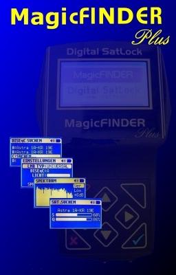
RS232 Connection. Graphic LCD Screen. Power Button. Charger Adapter Input LNB Output. MagicFINDER Digital SatLock Operating Manual
|
|
|
- Linette Leonard
- 5 years ago
- Views:
Transcription
1
 with Quantity and Bar. Display of timing detection and shift.")
2 GENERAL FEATURES Easy-to-understand user-friendly menu and keypad. LNB short circuit protection. Display of Analog Signal Level, Digital Signal Quality with % and Bar, audible notification. Timer Lock, Data Lock and Digital Signal FEC type display. Display of Digital Signal QBER (Bit Error Ratio) with Quantity and Bar. Display of timing detection and shift. Display of true carrier wave frequency and shift. Rapid spectrum analysis and display and satellite recognition function. Language options of Turkish, English, Dutch, and German. Satellite and TP list updating with the RS232 connection. Automatic shut down function. Quick charge system and long term use with a single charge. DiseqC Command support and DiseqC scanning function for Multiswitch and DiseqC switches. 32 Satellites, 256 TP Memories RS232 Connection Graphic LCD Screen Power Button Value Change Buttons Function Selection Buttons Back Button Charger Adapter Input OK Button LNB Input LNB Output
3 Turning the device ON/OFF To turn the device ON, hold the Power Button pressed for approximately 2 seconds. The logo will be displayed on the screen and the device will become ready for use. To turn the device OFF, at the Main Menu, hold the Power Button pressed for approximately 2 seconds. The device will shut down. If the battery level is very low, the device may not turn ON. Please wait until the charging process is completed. If the battery level drops below the critical level while the device is in use, the device will shut down automatically. This may be monitored with the flashing battery image on the top right-hand corner when the critical level is reached. Automatic Shut Down Function The SatLock device is equipped with the automatic shut down function to prevent unnecessary energy consumption. If the device is idle for approximately 5 minutes in any menu without pressing any keys, it will first automatically exit the menu in use and return to the main menu. If no operation is performed for the 5 minutes after this, the device will shut down automatically. Battery Charge System The SatLock device is supported with high technology Lithium-Ion batteries. This allows a long period of measuring and adjustment with a single charge. Furthermore, as these batteries have no memory impact, they may be charged whenever desired. There is no need to wait until they are completely discharged. The SatLock device charges batteries in two stages. The charging process will start when you attach the 12VDC charger adapter or the vehicle charger apparatus provided with the device to the Charger Adapter Input. According to the state of the battery, first, quick charge will be applied, and later the 100% section of the battery capacity will be filled in a healthy way with slow charge. If the device is OFF when the charge process is started, a battery image will be displayed on the screen and the charge status can be monitored with the moving bar in the battery. If the charge process is started when the device is ON, the same visual monitoring may be performed with the battery icon in the top right-hand corner. A moving bar will be displayed in the battery when quick charge is continuing. When the quick charge process is completed, a full battery image is displayed, which means that 80% of the device battery has been filled and the device is ready for use. However, there is benefit in leaving the device on charge for 1 more hour for the battery capacity to be 100% full with the slow charge process. The total charge time for completely discharged batteries may exceed 2 hours. If the device is in use during the charging process, the charge time will be longer. If the device is not going to be used for a long time, you must fully charge it in order to prevent the lifespan of batteries from shortening. Even if the device is not going to be used for a long time, it is recommended that you charge it max. once every three months. Because if lithium-ion batteries are left uncharged for long periods, their lifespan may shorten. Do not apply voltage higher than 24VDC on the charge input. Use a min. charger adapter of 1A. Adapters with a lower value may not charge the batteries fully even if you see the charging message on the screen. It is recommended that you do not use the device during the charging process. Because the ground returns between the network to which the charger adapter is connected and the networks of sources such as LNB, Receiver, Multiswitch with which measures are taken may cause serious damage on the device. The device must be simultaneously grounded from a single point only. There may be decrease in the battery performance in very cold weathers due to the chemical structure of lithium-ion batteries. This is normal.


4 LNB Short Circuit Protection The SatLock device LNB power supply unit is equipped with an active short circuit protection system. When the LNB input is short circuited or draws an above normal current during measurement, the short circuit protection is enabled and SHORT CIRCUIT is displayed on the screen. Also, an audible alert is sounded with a constant beep. When the short circuit or the over current state is eliminated, the device returns to the last function in which measurement was made, and the measurement process is stopped. The measurement process should be restarted after troubleshooting. Short circuits do not cause any damage to the device. MAIN MENU You can select the menu that you want to use with the Function Selection Buttons, and by pressing the OK Button you enter the selected menu. When in this screen, the device may be turned OFF by holding the Power Button pressed for 2 seconds. Other buttons are nonfunctional in this screen. MANUAL SEARCH In line 1, one of the 32 satellites in the memory are selected. To change the satellite, you move to the UYD (satellite) line with the Function Selection Buttons, and change the satellite with the Value Change Buttons. By holding the Value Change Buttons, you can change quickly between the satellites. In line 2, one of the 8 TP s entered for the relative satellite is selected. The selection method is the same. You go to the PRG line with the Function Selection Buttons and change the TP with the Value Change" Buttons. In line 3, as TP is changed, the Frequency, Polarization, and Symbol Rate will be displayed for the selected TP. The OK Button is used to start the signal measurement process. The Back Button may be used to return to the main menu. In the measurement screen, S and the Analog Signal Level are displayed as % and Bar. If the digital carrier cannot be caught, SEARCHING is displayed in line 2. When the Timing Value for the Digital Signal is caught, the key icon is displayed under PRG, and the Digital Signal / Band Noise rate is given in the bottom line with Q. Also, an increasing audible alert and LNB setting may be made as the Signal/Noise rate increases. If both Timing and Data are caught, the LOCK icon appears next to the key icon. In this case it means that the LNB setting is completed.


5 You may use the OK Button to reach detailed information such as more precise setting and QBER, True Frequency. SATELLITE DETECTION / IDENTIFICATION When you enter the sensitive adjustment screen, the TP name selected in the title section is displayed. Respectively, FQR and the true carrier frequency in which the broadcast is, BDR and the true Symbol/Seconds ratio for the broadcast, the FEC Value, and the QBER rate are displayed. The frequency shift LNB may be determined by checking the values in the first two lines. Also, the key values for the Carrier Wave and Timing loop are specified with the key icons to the right of the lines. If a question mark is displayed, this means that the carrier wave or the timing value has not been determined. In the BER section, the error rate is displayed in writing and with the Bar. The lower the BER rate, the better and cleaner the quality of the broadcast. Sensitive adjustment may be made in LNB with the BER indicator. The Back Button is used to exit these screens. On this screen, the S and Q show the Analog Signal Level and the Digital noise rate like in the Manual search menu. If a digital data is caught, and if there is an attempt to identify which satellite this data belongs to, and the attempt is a successful one, the name of the satellite identified is written on the screen. This is how the satellite identification system works: At the moment any digital data is identified, it is compared to the first TP information for the top 12 satellites in the memory. If any of the top 12 satellites are in accord with the TP's in the top rows, the name of the satellite in accord is written. Therefore, do not forget that when updating TP information from the PC, only the top 12 satellites are used in this function. Also, since only the first TP information for the top 12 satellites are going to be compared, make sure that the first TP information are current. Otherwise, this function will not operate well. Furthermore, to accelerate the speed of Satellite identification, make sure that the Symbol rate for the first TP information is high. Because TP s with high symbol rates can technically be detected much quicker. The recommended Symbol rate is at least 22MS/Seconds. Finally, to prevent incorrect identification on this screen, make sure that the first TP information that you have entered does not conflict amongst different satellites. For example, if there is a TP on Hotbird and Turksat with the same frequency and symbol rate, do not write this in the first row. The Back Button is used to exit from this screen.


6 DiseqC SEARCH SPECTRUM ANALYSIS In Multiswitch systems, this menu is used to figure out which satellite is in which channel. The potential 4 DiseqC port is scanned. If any digital data is caught, an attempt is made to identify which satellite the data belongs to, and if identified, it is written next to the relative DiseqC port. The satellite identification system is identical with the "Satellite Search / Identification" menu. Thus, the same measures are valid for this screen as well. The Back Button is used to exit from this screen. Spectrum Analysis is the screen which enables the display of the analog signal levels received by scanning the frequency band in the MHz range on the graphic screen. The peak points on the screen show the parts that are strong in terms of the signal. With the options on the right-hand side of the screen, respectively, the Horizontal/Vertical polarization selection, Upper-Lower band selection, Signal level, Noise Filter, DiseqC port selection may be made. You can move to the desired option with the Function Selection Buttons, and make the selection with the Value Change Buttons. The graph on the screen is examined after the Polarization and Band selection is made. If the signal levels are very low or very high, the db value may be changed to enable easy monitoring. Generally the noise section that remains low at the spectrum curve does not mean anything. The Noise Filter may be activated to prevent the display of this field. In this case, SUPP will be displayed in line 4, and the section remaining under the curve will not be drawn. With the DiseqC option in the last line, any DiseqC port may be selected. Through this, signals received from various ports may be compared. The spectrum screen may be used during satellite search as it operated fast. After LNB is set in a way that the values on the screen are at the highest level, it is possible to find to which satellite the curve belongs to with the Quick Satellite Identification function. Pressing the OK Button is enough for this process.


7 SETTINGS If the satellite can be identified, the satellite name will be written on top of the Spectrum Graph. The satellite identification system operates similarly to the previous menus. Thus, the same precautions are valid for this screen as well. The Back Button is used to exit from these screens. This is the section in which all device settings are made. The required parameter is selected with the Function Selection Buttons, and the value may be changed with the Value Change Buttons. In line 1, the LNB Type is selected. In line 2, the DiseqC port selection is made. It must be left closed at times it is not used. Measurement operations will be accelerated because of this. If a value is selected here, the device will spend time to send the required DiseqC commands before each measurement. In line 3, the intensity of the screen backlight may be adjusted. It is recommended that you do not keep it any higher than necessary. Because it will decrease the lifespan of your battery even if by little. In line 4, the device volume output may be turned up and down. In line 5, the device language may be selected. If the OK Button is pressed after the selections are made, the changes are saved and the device returns to the Main Menu. If the Back Button is used, you will return to the Main Menu without saving the changes that were made.
8 Technical Specifications Battery 8.4V 2000mA Lithium-Ion Type LNB Signal Level -65dBm / -25dBm LNB Input Socket F Female Type LNB Feeder 13/18V, Max 600mA 0/22KHz 1Vpp modulation With short circuit protection LNB Input Impedance 75Ohm Symbol Rate Ksymbol/Seconds Supported FEC 1/2, 2/3, 3/4, 5/6, 7/8 (Automatic) Frequency Range MHz Polarization Selection 13/18 V (LNB, DiseqC Switch) DiseqC (Multiswitch) Band Selection 0/22KHz (LNB, DiseqC Switch) DiseqC (Multiswitch) DiseqC Interface 2.0 Satellite Memory 32 Number of TP s Per Satellite 8 (Total 32x8=256 TP) Supported LNB s Universal OneTouch Single C Single Keypad Keys Charger Adapter 12VDC 1A SMPS
9
SATFINDER 3 HD SLIM USER GUIDE
 SATFINDER 3 HD SLIM USER GUIDE INDEX General Safety..... 3 Key Features..... 4 Panel Keypads... 5 Accesory.. 6 Satellite Search...... 7 Spectrum..... 8 Cross Polarisation... 9 Packet TP Levels.... 9 Multi
SATFINDER4 INTRODUCTION USER GUIDE AND CERTIFICATE OF GUARANTEE
 SATFINDER4 INTRODUCTION USER GUIDE AND CERTIFICATE OF GUARANTEE CONTENTS : General Safety...... 3 Basic Properties.... 4 Front Panel Keys... 5 Back Panel Details 5 Charger Adapters.. 6 Utilization of Satfinder4......
ATLANTA ASF 2033HD+ DVB-S/S2 METER. User`s Manual
 ATLANTA ASF 2033HD+ DVB-S/S2 METER User`s Manual Buttons and Indicators... 2 How to measure... 3 Main menu... 4 LNB Setting... 4 Edit Satellite... 6 Spectrum Chart... 7 Constellation... 9 Angle Calculation...
User s Manual of Signal Level Meter TABLE OF CONTENTS
 TABLE OF CONTENTS A OVERVIEW OF SIGNAL LEVEL METER...2 B FEATURES OF SIGNAL LEVEL METER...2 C PRECAUTIONS...2 D PANEL AND LCD...3 E INSTRUCTIONS OF KEYS...3 1. SINGLE-CHANNEL MEASUREMENT...4 2. SINGLE-FREQUENCY
Owner s Manual. Sat-Meter MSK 15. Order No.:
 Owner s Manual Sat-Meter MSK 15 Order No.: 217 100 13 Thank you for choosing our latest and most innovative satellite meter. It has been designed and manufactured to a very high standard and offers a UNIQUE
PCM-1210 DVB COMBO METER User`s Manual
 PCM-1210 DVB COMBO METER User`s Manual 1. Main Features... 1 2. Buttons and Indicators... 2 3. How to measure... 3 4. Home menu... 4 5. Satellite... 4 5.1 Satellite Measure... 4 5.2 LNB Setting... 5 5.3
STM 17 HD. DVB-S2+T2/C Compact Meter. User Manual. Ref R13. CAHORS Digital CS Cahors Cedex 9 FRANCE.
 STM 17 HD DVB-S2+T2/C Compact Meter User Manual Ref 0145131R13 DVB COMBO METER 1. Main Features... 2 2. Buttons and Indicators... 3 3. How to measure... 4 4. Home menu... 5 5. Satellite... 5 5.1 Satellite
SZU OPERATING INSTRUCTIONS SAT NAVI
 SZU 21-00 O P ER ATI N G I N S T R U C T I O N S SAT NAVI Operation Instructions SZU 21-00 Safety Notes Turn off the receiver or any used power supply before installing, to avoid short-circuit. Installation
DIGITAL SATELLITE METER
 DIGITAL SATELLITE METER THE PROFESSIONAL EQUIPMENT DIGITAL SATELLITE METER THE PROFESSIONAL EQUIPMENT USER S MANUAL Product Description 1.Guide 2. Menu 1.1 Face Panel & Button 1.2 Power On/Off 1.3Power
Horizon HD-STM. Combo Signal Analyzer TEST REPORT
 TEST REPORT Combo Signal Analyzer Horizon HD-STM can be used intuitively, manual is not needed perfect workmanship optimized for the day-to-day work of an installer gives all the "Must-Have" informations
XR-3 QAM 8VSB. Modular Test Instrument. XR-3 Rugged Adaptable Economically Efficient Configurable to test: and more
 XR-3 Modular Test Instrument XR-3 Rugged Adaptable Economically Efficient Configurable to test: and more QAM 8VSB XR-3 Modular Test Instrument GENERAL FEATURES Durable case with rubber shock guards Color
DIGISAT MULTI USER MANUAL
 DIGISAT MULTI USER MANUAL CONTENTS: Meter specifications page 3 Accessories included page 3 Description page 4 Charging the batteries page 5 Controls and Features page 6 Hi Resolution Mode page 7 Audio
Xsarius Satmeter Pro. Manual
 Xsarius Satmeter Pro Manual 1 2 Directory of content Introduction Directory of content 3 Introduction 3 Satmeter Pro 02 Frontpanel & buttons 6 Xsarius provides high quality products that enable you to
SM-10 SAT Level Meter User s Manual
 SM-10 SAT Level Meter User s Manual DAGATRONICS CORPORATION 263-1 DUCKIDONG, ILSAN, KOYANG, KYUNGKIDO, KOREA TEL: +82-31-916-8005 FAX: +82-31-916-8080 Email: dagatron@dagatron.com Website: www.dagatron.com
Specifications. Dual Satellite Tracking Meter. With a built in 22Khz tone generator. Overview
 Dual Satellite Tracking Meter 38.8 With a built in Khz tone generator Specifications Power demand over 800 ma will result in an Over Current indication. Compatible With STARBAND Receivers Input Frequency:
SATELLITE FINDER SK-3200 USER MANUAL
 SATELLITE FINDER SK-3200 USER MANUAL CONTENTS 1. GUIDE...1 1.1 IMPORTANT SAFETY INSTRUCTIONS... 1 1.2 UNPACKING...1 1.3 PRODUCT OVERVIEW & ILLUSTRATION... 2 2. OUTLINE...4 3. THE MENU OSD INSTRUCTION...5
Satellite locator WS-6933
 R Satellite locator WS-6933 User's Manual English CONTENTS 1. GUIDE...2 1.1 IMPORTANT SAFETY INSTRUCTIONS...2 1.2 UNPACKING...2 1.3 PRODUCT OVERVIEW&ILLUSTRATION...3 2. OUTLINE...4 3. THE MENU OSD INSTRUCTION...5
Super Installer Lite USER MANUAL
 Super Installer Lite USER MANUAL Contents Super Installer Lite - Description..... page 3 Getting Started........ page 4 Power On/Off Power Supply and Battery How to use the meter Menu.......... page 7
15 Inch CGA EGA VGA to XGA LCD Wide Viewing Angle Panel ID# 833
 15 Inch CGA EGA VGA to XGA LCD Wide Viewing Angle Panel ID# 833 Operation Manual Introduction This monitor is an open frame LCD Panel monitor. It features the VESA plug & play system which allows the monitor
Digital Terrestrial Alignment & Installation Meter
 Digital Terrestrial Alignment & Installation Meter Instruction Booklet Version 3 - February 2005 www.horizonhge.com Thank you for choosing our latest and most innovative terrestrial meter. It has been
All the functions you need in your hand
 All the functions you need in your hand Rely on H30FLEX for installation and troubleshooting. Robust, light-weight and extremely easy to use. Carry out installation, maintenance and troubleshooting tasks
Owner's Manual. All information in this publication is based on the latest product information available at the time of printing.
 STARLOOK- D Manual You are entitled to the manufacturer's limited express warranty, if any, that accompanies the product. DAWNco makes no additional or independent warranty. All other warranties, express
Sattracker Digital Satellite Receiver
 SATTRACKER DIGITAL SATELLITE RECEIVER INDEX 1. GENERAL INTRODUCTION 2. KEY SET AND SPECIALITIES 3. MENUS 4.GENERAL USAGE 5. MANUEL SATELLITE FINDER 6. SATELLITE FINDER 7. PACKAGE CONTROL 8. SPECTRUM 9.
SATFINDER 3 HD USER GUIDE
 INDEX General Safety..... 3 Key Features..... 4 Panel Keypads... 5 Accesory.. 6 Satellite Search...... 7 Spectrum..... 8 Cross Polarisation... 9 Packet TP Levels.... 9 Multi Levels....... 9 Constellation.....
HD-TM PLUS HORIZON DIGITAL TERRESTRIAL METER
 HD-TM PLUS OFF MENU INPUT ON HORIZON DIGITAL TERRESTRIAL METER Horizon Global Electronics Ltd. Unit 3, West Side Flex Meadow Harlow, Essex CM19 5SR Phone: +44(0) 1279 417005 Fax: +44(0) 1279 417025 Issue
Dragon. manual version 1.6
 Dragon manual version 1.6 Contents DRAGON TOP PANEL... 2 DRAGON STARTUP... 2 DRAGON STARTUP SCREEN... 2 DRAGON INFO SCREEN... 3 DRAGON MAIN SCREEN... 3 TURNING ON A TRANSMITTER... 4 CHANGING MAIN SCREEN
WS-6932 USER S MANUAL USER S MANUAL
 WS-6932 USER S MANUAL USER S MANUAL Product Description CONTENTS GUIDE 1.1 Face Panel & Button 1.2 Power On/Off 1.3Power Supply & Battery Menu 2.1 Satellite Search 2.2 Multimedia 2.3 System Setting 2.4
HD Satellite Finder Meter
 WS-6922 HD Satellite Finder Meter HD Satellite Finder Meter USER S MANUAL WS-6922 USER S MANUAL Product Description 1.Guide 2. Menu CONTENTS 1.1 Face Panel & Button 1.2 Power On/Off 1.3Power Supply & Battery
HD-CM HORIZON DIGITAL CABLE METER
 HD-CM OFF! Max RF i/p = +17dBm 75Ω Max AC/DC i/p = 120Vrms MENU INPUT ON HORIZON DIGITAL CABLE METER Horizon Global Electronics Ltd. Unit 3, West Side Flex Meadow Harlow, Essex CM19 5SR Phone: +44(0) 1279
SNG-2150C User s Guide
 SNG-2150C User s Guide Avcom of Virginia SNG-2150C User s Guide 7730 Whitepine Road Revision 001 Richmond, VA 23237 USA GENERAL SAFETY If one or more components of your earth station are connected to 120
Noise Detector ND-1 Operating Manual
 Noise Detector ND-1 Operating Manual SPECTRADYNAMICS, INC 1849 Cherry St. Unit 2 Louisville, CO 80027 Phone: (303) 665-1852 Fax: (303) 604-6088 Table of Contents ND-1 Description...... 3 Safety and Preparation
innovative technology to keep you a step ahead Tailored to Simplify Installation and Troubleshooting of RF Signals
 Tailored to Simplify Installation and Troubleshooting of RF Signals Intuitive Color Display with Simple Pass/ Fail Indicators Reduce Installer Entry Errors and Improves Decision Making Autotests Streamline
Model Three Signal Level Meter. Operation Manual
 Model Three Signal Level Meter Operation Manual Trilithic Company Profile Trilithic is a privately held manufacturer founded in 1986 as an engineering and assembly company that built and designed customer-directed
STM 26 HD. DVB-S2+T2/C Compact meter User Manual. Ref R13. CAHORS Digital CS Cahors Cedex 9 FRANCE
 STM 26 HD DVB-S2+T2/C Compact meter User Manual Ref 0145225R13 Preface USER MANUAL Please read this manual carefully before using your Digital Sat meter for the first time. This operating manual will help
Hardware & software Specifications
 Hardware & software Specifications Réf : PRELIMINARY JUNE 2007 Page 2 of 17 1. PRODUCT OVERVIEW...3 2. TERMINOLOGY...4 A. THE FRONT PANEL...4 B. THE REAR PANEL...5 3. SCREENS DESCRIPTION...5 A. MAIN SCREEN
INSTRUCTION MANUAL SATELLITE. Version V4.0. NTi R. NTi. 13V[] 17V[] 22Kc[]> TBrst[] DiSEqC[] ü. Edition 11/2004 DILAN 2150 SAT LEVEL METER
![INSTRUCTION MANUAL SATELLITE. Version V4.0. NTi R. NTi. 13V[] 17V[] 22Kc[]> TBrst[] DiSEqC[] ü. Edition 11/2004 DILAN 2150 SAT LEVEL METER](/thumbs/85/92438894.jpg "INSTRUCTION MANUAL SATELLITE. Version V4.0. NTi R. NTi. 13V[] 17V[] 22Kc[]> TBrst[] DiSEqC[] ü. Edition 11/2004 DILAN 2150 SAT LEVEL METER") C/N FEC dbuv VITERBI REED-SOLOMON DVB MPEG-2 QPSK BER FEC QPSK C/N FEC dbuv VITERBIREED-SOLOMON DVB MPEG- 2 QPSK BER C/N FEC dbuv VITERBI REED- SOLOMON DVB MPEG QPSK C/N FEC dbuv VITERBI REED-SOLOMON DVB
C/N FEC dbuv VITERBI REED-SOLOMON DVB MPEG-2 QPSK BER FEC QPSK C/N FEC dbuv VITERBIREED-SOLOMON DVB MPEG- 2 QPSK BER C/N FEC dbuv VITERBI REED- SOLOMON DVB MPEG QPSK C/N FEC dbuv VITERBI REED-SOLOMON DVB
ST-4000 SIGNAL LEVEL METER
 ST-4000 SIGNAL LEVEL METER Table of Contents Features / Specifications.... 1 Keypad Illustration....... 2 Keypad Controls.... 2 Getting Started: Powering the Meter.... 3 Quick Use Instructions.. 3 Main
CATV & DOCSIS3.0 Meter / Analyzer. Purchase from:
 EN CATV & DOCSIS3.0 Meter / Analyzer Overview Introducing the H30. New from Televes, a go-to meter designed with the needs of a Cable TV operator in mind. The H30 is a light weight, rugged unit, packed
26 Inch CGA/EGA/VGA/DVI to WXGA/1080p LCD - ID#703
 26 Inch CGA/EGA/VGA/DVI to WXGA/1080p LCD - ID#703 Operation Manual Introduction This monitor is an open frame LCD Panel monitor. It features the VESA plug & play system which allows the monitor to automatically
Single cable multiswich programmer PC102W
 Single cable multiswich programmer PC102W 1. Product description The PC102W - single cable multiswich programmer (in the text - programmer) is useful instrument while configuring and troubleshooting SAT
8dtek DSM Desired. Business Voucher Direct Contact to Sales Manager. TELE-satellite Magazine
 TEST REPORT 该独家报道由技术专家所作 Satellite Signal Analyzer 8dtek DSM Desired includes features normally only found in much higher priced products shows constellation and spectrum handles all DiSEqC variants including
Component Video Matrix Switcher Series ITEM NO.: YS04MA, YS04MD
 Component Video Matrix Switcher Series ITEM NO.: YS04MA, YS04MD Our component video switcher allows four different component video and stereo/digital audio sources to share two video displays. Manage multiple
High Performance Outdoor Test Translators
 Input Output LO Frequency Frequency Frequency Model (GHz) (GHz) (GHz) Number RF Transmit-Band to RF Receive-Band 5.85 6.425 3.625 4.2 2.225 DN-WS-6.1/3.9 5.85 6.65 3.4 4.2 2.45 DN-WS-6.25/3.8 6.725 7.025
2W Wireless Mobile Video Transmitter (ST6000TKMD) User Manual
 User Manual") 2W Wireless Mobile Video Transmitter (ST6000TKMD) User Manual TENG YUANZHI SHENZHEN ELECTRONICS CO.,LTD. 2010.10.23 1 Features Low system latency COFDM modulation, Stable transmission MPEG-2 video compression,
2W Wireless Mobile Video Transmitter (ST6000TKMD) User Manual TENG YUANZHI SHENZHEN ELECTRONICS CO.,LTD. 2010.10.23 1 Features Low system latency COFDM modulation, Stable transmission MPEG-2 video compression,
Satellite Signal Meter TEST REPORT 该独家报道由技术专家所作. 8dtek DSM Gifted. 30 TELE-satellite Global Digital TV Magazine 06-07/2011
 TEST REPORT 该独家报道由技术专家所作 Satellite Signal Meter 8dtek DSM Gifted 30 TELE-satellite Global Digital TV Magazine 06-07/2011 www.tele-satellite.com measures all tv signals in DVB-S, DVB-S2 and even the old
Universal DiSEqC controller USER MANUAL
 Universal USER MANUAL SAT CONTROL 1. INTRODUCTION Satellite television is one of most favourite and popular medium in today s world. But reception 36.000 km away from the sky is more technically difficult.
Universal DiSEqC controller USER MANUAL SAT CONTROL
 USER MANUAL SAT CONTROL SAT CONTROL Dear customer, If you have not been able to put the system into operation or have problems installing it, call the Technical Assistance phone as indicated on the first
innovative technology to keep you a step ahead Tailored to Simplify Installation and Troubleshooting of RF Signals
 Tailored to Simplify Installation and Troubleshooting of RF Signals Intuitive Color Display with Simple Pass/ Fail Indicators Reduce Installer Entry Errors and Improve Decision Making Autotests Streamline
VM-100R. 1 RU HEIGHT PROGRAMMABLE 70 AND 140 MHz HIGH-PERFORMANCE VIDEO/AUDIO MODULATOR
 VM-100R 1 RU HEIGHT PROGRAMMABLE 70 AND 140 MHz HIGH-PERFORMANCE VIDEO/AUDIO MODULATOR OPTIONS Up to four internal programmable audio subcarrier modulators Support full I:N redundant multiformat configurations,
Unicable II Programmer. IDLU-PROG01-OOOOO-OPP Item: Installation & User Guide
 Unicable II Programmer IDLU-PROG01-OOOOO-OPP Item: 5273 Installation & User Guide 1 2 Thank you for purchasing Inverto s advanced Unicable II programmer. Before installing and using the programmer, please
MODEL OTM-4870 FREQUENCY AGILE 870MHz F.C.C. COMPATIBLE TELEVISION MODULATOR
 MODEL OTM-4870 FREQUENCY AGILE 870MHz F.C.C. COMPATIBLE TELEVISION MODULATOR USERS MANUAL Phone: (209) 586-1022 (800) 545-1022 Fax: (209) 586-1026 E-Mail: salessupport@olsontech.com 025-000412 Rev. B www.olsontech.com
Super Buddy Operation Manual
 Operation Manual Revision 2.00 Date 10/23/2007 1. INTRODUCTION...4 CONNECTIONS... 4 IRD CONNECTION... 5 PC CONNECTION... 5 2. RUN SCREEN...5 DISPLAYED DATA... 5 SOFT KEYS... 6 CHANGING SATELLITES... 6
User Guide. TMDS 5x C Digital SCR Multiswitch for SkyQ. Version B Date 02/2016 EN TMDS 54 C TMDS 58 C
 User Guide TMDS 5x C Digital SCR Multiswitch for SkyQ Model Item no. TMDS 54 C 307370 TMDS 58 C 307378 Version 891601B Date 02/2016 Attention! Failure to comply with the specified precautionary measures
COMBOLOOK. Manual English. Version: 2.00
 COMBOLOOK Manual English Version: 2.00 1 Owner's Manual Thank You for purchasing a Emitor AB COMBOLOOK-instrument. This manual covers the operation and maintenance of the Emitor AB COMBOLOOKinstrument
ST-4000D SIGNAL LEVEL METER
 ST-4000D SIGNAL LEVEL METER Rev 100606 Table of Contents Features / Specifications.... 1 Keypad Illustration....... 2 Keypad Controls.... 2 Getting Started: Powering the Meter...... 3 Quick Use Instructions.....
M5-H002. Multiview T-35. DVB-T to PAL / 5 channels on all TV s
 120531 M5-H002 Multiview T-35 DVB-T to PAL / 5 channels on all TV s Contents Multiview... 3 Features... 3 Caution... 3 Front & Rear Panel... 4 Connecting... 5 Programming... 6 Information... 7 Installation...8
V/L V/H H/L H/H. Satellite - Input. Programmable Cascadable switch. with 32 User Bands with Terrestrial input & 1 Legacy port
 : 47-862MHz For default UB frequencies: Unicable II Multiswitch 32 User Bands with & 1 Legacy port Installation manual 1 2 Thank you for purchasing Inverto s advanced multiswitch and we are certain it
12.1 Inch CGA EGA VGA SVGA LCD Panel - ID #492
 12.1 Inch CGA EGA VGA SVGA LCD Panel - ID #492 Operation Manual Introduction This monitor is an open frame LCD Panel monitor. It features the VESA plug & play system which allows the monitor to automatically
Model Two and Model Two Lite Signal Level Meters OPERATION MANUAL
 Model Two and Model Two Lite Signal Level Meters OPERATION MANUAL Trilithic Company Profile Trilithic is a privately held manufacturer founded in 1986 as an engineering and assembly company that built
TV4U QUAD DVB-S2 to DVB-C TRANSMODULATOR
 INSTRUCTION MANUAL Features of the new DVB-C transmodulators line Through the use of the FPGA technology the transmodulators provides the highest performance at the lowest price. Four carriers are formed
SAM. Satellite Meter. User Manual. Ver: 0814us
 Ver: 0814us SAM Satellite Meter User Manual Notes. 3 Table of contents 1. Introduction... 2 Chapter Page 2. Supplied items... 3 3. Getting started 1. Creating a Maxpeak user profi le... 4 2. Product registration,
What's included? RCU. Easy Setup Guide. HDMI Cable. Loop-through Cable. Power Cord. SATA Cable. RCU Battery
 English What's included? RCU Easy Setup Guide HDMI Cable SATA Cable Power Cord Loop-through Cable RCU Battery 1 Front Panel LCD Display Displays graphic logos of channels and uploaded user s favorite images.
Redcare signal strength tester user manual.
 Redcare signal strength tester user manual. Page 1 Issue Apr 2012 Product description. The redcare GSM/GPRS Signal Strength Tester has been developed to help Security and Fire Alarm installers or engineers
INT-DS2 DVB-S/S2 SATELLITE MODULATOR DVB MODULATOR
 INT-DS2 DVB-S/S2 SATELLITE MODULATOR Key Features In compliance with DVB-S/S2/DSNG and in partial compliance with DVB-S2x standards. Supporting up to 200Mbps at ASI and 80Mbps at TSoIP input. Capable to
RF4432 wireless transceiver module
 RF4432 wireless transceiver module 1. Description RF4432 adopts Silicon Lab Si4432 RF chip, which is a highly integrated wireless ISM band transceiver. The features of high sensitivity (-121 dbm), +20
RF Explorer RackPRO. User Manual. Introduction. Greetings fellow traveler on the RF spectrum.
 RF Explorer RackPRO User Manual Introduction Greetings fellow traveler on the RF spectrum. The RF Explorer RackPRO (referred to in this document in shorthand as RackPRO ) has been designed to be intuitive
Sunrise Telecom, Hukk Division
 Established 1981 Advanced Test Equipment Rentals www.atecorp.com 800-404-ATEC (2832) Sunrise Telecom, Hukk Division CR1200R Manual Contents (Rev. B) CHAPTER 1 - GENERAL INFORMATION A general description
Ku-Band Redundant LNB Systems. 1:1 System RF IN (WR75) TEST IN -40 db OFFLINE IN CONTROLLER. 1:2 System POL 1 IN (WR75) TEST IN -40 db POL 2 IN
 TEST IN -40 db OFFLINE IN CONTROLLER. 1:2 System POL 1 IN (WR75) TEST IN -40 db POL 2 IN") BRK-1000 Series Ku-Band Redundant LNB Systems Introduction Redundant LNB systems minimize system downtime due to LNB failure by providing a spare LNB and an automatic means of switching to the spare upon
BRK-1000 Series Ku-Band Redundant LNB Systems Introduction Redundant LNB systems minimize system downtime due to LNB failure by providing a spare LNB and an automatic means of switching to the spare upon
Advanced HDTV System Analyzers
 H45 FIRST HANDHELD System Analyzer WITH DIGITAL PROCESSING Advance SERIES Advanced HDTV System Analyzers HDTV testing made simple - One single tool covers every testing need MPEG-4 FULL HD 1080P CABLE
2 MHz Lock-In Amplifier
 2 MHz Lock-In Amplifier SR865 2 MHz dual phase lock-in amplifier SR865 2 MHz Lock-In Amplifier 1 mhz to 2 MHz frequency range Dual reference mode Low-noise current and voltage inputs Touchscreen data display
Rack-Mount Receiver Analyzer 101
 Rack-Mount Receiver Analyzer 101 A Decade s Worth of Innovation No part of this document may be circulated, quoted, or reproduced for distribution without prior written approval from Quasonix, Inc. Copyright
JD725A Cable and Antenna Analyzer - Dual Port
 COMMUNICATIONS TEST & MEASUREMENT SOLUTIONS JD725A Cable and Antenna Analyzer - Dual Port Key Features Portable and lightweight handheld instrument Built-in wireless frequency bands as well as the most
MSK 120 From software version V1.3
 Operating manual DIGITAL-SAT-METER MSK 120 From software version V1.3 FOREWORD/IMPORTANT INSTRUCTIONS Dear customer, thank you for choosing the Kathrein MSK 120 satellite meter. Please read the following
OMNISTAR GX2. GX2-LM1000E Series 1310 nm Broadcast Transmitter DATA SHEET BENEFITS. 1 GHz bandwidth
 DATA SHEET BENEFITS OMNISTAR GX2 GX2-LM1000E Series 1310 nm Broadcast Transmitter 1 GHz bandwidth High module density up to 16 transmitter modules in a 4 RU housing High performance: Advanced predistortion
1. Update Software in Meter
 12/13/2016 Limit Scan Feature Revision Brief for the AI Turbo S2 Satellite Meter 1. Update Software in Meter To obtain the software that contains the revised Limit Scan feature as described in the document
Rain+Birdt. Landscape Irrigation & Maintenance Remote System. Quick Start Guide 4.00 F G H K 9X. c n. System Components
 Rain+Birdt Landscape Irrigation & Maintenance Remote System Quick Start Guide 4.00 D System Components A Transmitter (TX) B Receiver (RX) C Quick Connect (QC) 6-Pin Quick Connect (QC) for use with ESP-Modular
English CONTENTS 1. GUIDE OUTLINE THE MENU OSD INSTRUCTION TECHNICAL SPECIFICATION TROUBLE SHOOTING...
 English CONTENTS 1. GUIDE...2 1.1 IMPORTANT SAFETY INSTRUCTIONS...2 1.2 UNPACKING...2 1.3 PRODUCT OVERVIEW& ILLUSTRATION...3 1.4 INSTALLATION OF METER...4 2. OUTLINE...5 3. THE MENU OSD INSTRUCTION...6
Portable TV Meter (LCD) USER S MANUAL
 USER S MANUAL") 1 Portable TV Meter User Manual (LCD) Portable TV Meter (LCD) USER S MANUAL www.kvarta.net 1 / 19 2 Portable TV Meter User Manual (LCD) Contents 1. INTRODUCTION... 3 1.1. About KVARTA... 3 1.2. About DVB...
1 Portable TV Meter User Manual (LCD) Portable TV Meter (LCD) USER S MANUAL www.kvarta.net 1 / 19 2 Portable TV Meter User Manual (LCD) Contents 1. INTRODUCTION... 3 1.1. About KVARTA... 3 1.2. About DVB...
Quick installation and configuration guide STC
 Quick installation and configuration guide STC 200 REF. 4466 Contents 4 Introduction 4 General description 5 General use of the headend 6 Initial installation and configuration 6 Assembly, connection
Unicable II Cascadable switch with Terrestrial input and 4x Sky dscr/satcr/legacy+terrestrial outputs
 Unicable II Cascadable switch with Terrestrial input and 4x Sky dscr/satcr/legacy+terrestrial outputs Model: ISKY-UST110-CUO4O-16P Item: 5412 The Multiswitch unit connects to a Quattro LNB and offers a
OTM FREQUENCY AGILE 750MHz F.C.C. COMPATIBLE TELEVISION MODULATOR INSTRUCTION MANUAL
 OTM-4000 FREQUENCY AGILE 750MHz F.C.C. COMPATIBLE TELEVISION MODULATOR INSTRUCTION MANUAL Phone: (209) 586-1022 (800) 545-1022 Fax: (209) 586-1026 E-Mail: salessupport@olsontech.com 025-000331 REV B www.olsontech.com
XCOM1002JE (8602JE) Optical Receiver Manual
 Optical Receiver Manual") XCOM1002JE (8602JE) Optical Receiver Manual - 2 - 1. Product Summary XCOM1002JE (8602JE) outdoor optical receiver is our latest 1GHz optical receiver. With wide range receiving optical power, high output
XCOM1002JE (8602JE) Optical Receiver Manual - 2 - 1. Product Summary XCOM1002JE (8602JE) outdoor optical receiver is our latest 1GHz optical receiver. With wide range receiving optical power, high output
S7000 Series TV Analyzer Operation Manual
 S7000 Series TV Analyzer Operation Manual Version 1.51 TianJin Deviser Electronics Instrument Co., Ltd. All rights reserved. Printed in CHINA. Contents 1. The Basics... 1 1.1 General Information... 2
Quick Start. RSHS1000 Series Handheld Digital Oscilloscope
 Quick Start RSHS1000 Series Handheld Digital Oscilloscope General Safety Summary Carefully read the following safety precautions to avoid personal injury and prevent damage to the instrument or any products
Inmarsat Downconverter Narrowband Downconverter
 Visit us at www.w ork-microw ave.de Inmarsat Downconverter Narrowband Downconverter L-Band to 70/140 MHz S-Band to 725 MHz 140 MHz to 15 MHz Single Conversion Dual Channel Converters also available. These
THE ART OF ENGINEERING
 THE ART OF ENGINEERING L-Band Distributing Matrix 16² The final product may vary from the above image depending on the options selected. Product: DEV 1985/16x16 DEV 1985/16x8 16x16 Distributing Matrix
Field Strength Meter. Multimetter FSM 500. Ref
 Field Strength Meter Multimetter FSM 500 U s e r M a n u a l Ref. 5903 www.televes.com Index.................................................. Pg. 1.- INSTALLATION..........................................................
RF Mogul. Quick Start. Model: SDC1. Satellite Dish Controller
 RF Mogul Satellite Dish Controller Model: SDC1 Quick Start 29 February 2012 Minimum required hardware to find a Satellite! This Quick Start document is for connecting and operating a General Dynamics C125M
S7000L. TV & Satellite Analyzer. All IN ONE. Satellite & Terrestrial. Key Features. Model Guide
 S7000 TV & Satellite Analyzer Key Features All standards in one: QAM(J.83A/B/C), 8VSB, DVB-T/H/T2, DVB-S/ S2 Digital/Analog TV and Satellite TV analysis MPEG2 Transport stream analyzer and monitoring via
D R M A X - 2 DDS FREQUENCY SYNTHESIZED DRM MW TRANSMITTER. User s Guide (Please read carefully before using for the first time!)
") D R M A X - 2 DDS FREQUENCY SYNTHESIZED DRM MW TRANSMITTER User s Guide (Please read carefully before using for the first time!) Copyright 2018 by ASPiSYS Ltd. DRMAX2 is a low-power DRM MW transmitter.
D R M A X - 2 DDS FREQUENCY SYNTHESIZED DRM MW TRANSMITTER User s Guide (Please read carefully before using for the first time!) Copyright 2018 by ASPiSYS Ltd. DRMAX2 is a low-power DRM MW transmitter.
Instructions for setting up Freesat V7HD or V8 Golden
 Setting up the dish: The V8 Installation Menu / V7 Main Menu Instructions for setting up Freesat V7HD or V8 Golden Adding a Satellite: V8 Satellite list / V7 Satellite Installation Menu Press the red button
KVE vector Vector Impedance Antenna analyzer User's Manual ( V for Kve60C and Kve520A )
") KVE vector Vector Impedance Antenna analyzer User's Manual ( V20150108 for Kve60C and Kve520A ) 1.0 Introduction Features and Functions: The KVE anlyzer breaks the size barrier for RF-analyzers by delivering
KVE vector Vector Impedance Antenna analyzer User's Manual ( V20150108 for Kve60C and Kve520A ) 1.0 Introduction Features and Functions: The KVE anlyzer breaks the size barrier for RF-analyzers by delivering
EX04-000D. DVB-T/2xT/T2 MODULATOR DVB MODULATOR
 EX04-000D DVB-T/2xT/T2 MODULATOR Key Features Capable of transmitting one DVB-T2 or two independent DVB-T signals at the same time. In full compliance with the last version of EN300744 (DVB-T) and EN302755
SEFRAM 7870 series The feeling of a new way of measurement
 SEFRAM 7870 series The feeling of a new way of measurement 2 New aluminium housing with excellent robustness 10 inch panoramic touch screen HD TV decoding for all standards High brightness which makes
MSP 200PRO Quick Start
 MSP 200PRO Quick Start Touch Screen control Output a range of signal types Set and select from a range of common output formats Audio output test included Genlock Y&HS outputs Input live signals for preview
HDMI Matrix Switches. Product Data Sheet. Basic Features. Overview. Ordering Information
 AVSW-HDMI8X8-X AVSW-HDMI-RX VSW-HDMI4X4-B VSW-HDMI8X8-B Product Data Sheet HDMI Matrix Switches Overview The 4x4 or 8x8 HDMI Matrix Switch (VSW-HDMI4X4-B or VSW-HDMI8X8-B) from Black Box provides unrivaled
Please feel free to download the Demo application software from analogarts.com to help you follow this seminar.
 Hello, welcome to Analog Arts spectrum analyzer tutorial. Please feel free to download the Demo application software from analogarts.com to help you follow this seminar. For this presentation, we use a
English CONTENTS 1. GUIDE OUTLINE THE MENU OSD INSTRUCTION TECHNICAL SPECIFICATION...17
 USER S MANUAL English CONTENTS 1. GUIDE...2 1.1 IMPORTANT SAFETY INSTRUCTIONS...2 1.2 UNPACKING...2 1.3 PRODUCT OVERVIEW& ILLUSTRATION...3 1.4 INSTALLATION OF METER...4 2. OUTLINE...5 3. THE MENU OSD INSTRUCTION...6
AMIGO- 8VSB (ATSC) digital Modulator
 digital Modulator") - 8VSB (ATSC) digital Modulator With Linear & Non-Linear Pre-Distortion for HDTV Overview The LUMANTEK line of Solid State VHF/UHF 8VSB Digital Modulators offers an unparallel combination of features and
- 8VSB (ATSC) digital Modulator With Linear & Non-Linear Pre-Distortion for HDTV Overview The LUMANTEK line of Solid State VHF/UHF 8VSB Digital Modulators offers an unparallel combination of features and
DisplayMax 5000 P/A MER BER C/N MODEM INGRESS LEAKAGE CHANNEL FREQUENCY FAVORITE CHANNELS. DisplayMax 5000 SIGNAL LEVEL METER.
 Sadelco Signal Level Meters DisplayMax 5000 SLM Dig P/A MER BER C/N MODEM INGRESS LEAKAGE FAVORITE CHANNELS CHANNEL FREQUENCY ENTER MODEM 1 2 3 4 5 6 7 8 9 0. ESCAPE ON OFF Sadelco DisplayMax 5000 SIGNAL