User s manual. Digital control relay SVA
|
|
|
- Michael Reeves
- 5 years ago
- Views:
Transcription

1 User s manual Dgtal control relay
2 DISIBEINT ELECTRONIC S.L, has been present n the feld of the manufacture of components for the ndustral automaton for more than years, and mantans n constant evoluton ther wde range of products structured n fve famles: Sensors, magnetc swtches and transducers Level relays for lquds and solds Tmers Control, survellance and logc relays Dgtal control relay Data transmsson Our permanent preoccupaton s to gve a sutable answer to the problems that appear n the automaton of the dfferent ndustral processes, provdng the most sutable materal for each applcaton. GUARANTEE The products provded by DISIBEINT has a guarantee perod of two years, aganst all defect due to the materals or to the manufacture of the equpment. It does not cover the defects caused durng the transport or by a bad applcaton, nether the elements subject to wearng down, nor the drect or ndrect consequences caused n the nstallaton by the nadequate use of the equpment. Rev.0/00 0/0/0 DISIBEINT reserves the rght to modfy the specfcatons stated n ths document wthout prevous notce.
3 INDEX Descrpton and parts of the equpment... Techncal data... Qualty certfcate... Conventons used n ths manual... General concepts... Types of screen... Fast gude for beggnng... User programs... Advanced programmng... MENUS AND SCREENS Set up menu... Total number of modules... State of the relay s contact... State of the relay n alarm mode... Detecton/Release by modules... Detecton and release module... Detecton and/or release tmng... Readng unts... Top of scale... Loop -0 ma... RS... Optons menu... Save program... User program... Programs and... See screen... Edton of the user screen... Informaton of the model and verson... Screen refresh... Lockng parameters... Language... Complementary functons... Error messages... Outputs communcaton... Your notes
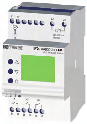
4 DESCRIPTION OF THE EQUIPMENT The model s a dgtal control relay for sngle phase voltages. The parameters that can be controlled are: - Maxmum and / or mnmum voltage. RMS value. - Maxmum and / or mnmum frequency. - Maxmum DC component. Operatons under the control of dfferent parameters can be assocated wth three relays, a -0 ma current loop or RS/RS seral communcaton. Each of the three avalable relays can be assgned the shot by one or more parameters. PARTS OF THE EQUIPMENT Phases nput Optons selecton Screen s selecton Change of values Text edton Supply voltage nput LCD screen Enter Sgnalng of the supply voltage and state of the relay Relays output

5 TECHNICAL DATA (/) Functon Workng mode Dsplay to read value Output Detecton/ Release Tmer Repeatblty Tme range Precson VAC Frequency Precson -0 ma Voltage relay for sngle-phase lnes. Control of own supply voltage. User confgurable. Each of the three relays avalable can be assgned ts drve for one or more magntudes, makng t the frst stuaton to occur. By the followng status dsplays: TENSION: Tenson lína. FREQUENCY: Frequency of the lne. DC COMPONENT: contnuous component of the lne - From.. ndependent relays - Analog -0 ma (optonal) - Communcaton RS - RS (optonal) All fgures may be desgnated the detect and/or replacement value. It s assocated wth the acton of the relay. Adjustable detecton and/or replacement. Multple functons. ± 0 ppm 0,0.., s 0,0.., m 0,.., h Taken on the value beng measured 0 Hz: 0.% 60 Hz: 0.% 0.% % addtonal to the equpment value. Connecton Dmensons
6 TECHNICAL DATA (/) Output relays Resstve load Inductve AC DC AC load DC Mechancal lfe Mech. swtchng rate Elect. lfe at full load Contact materal Operatng voltage Volt. between contacts Volt. col/contact Isolaton resstance Indcaton 6 A / 0 V 6 A / V A / 0 V A / V > 6 oper..000 oper. / hour 60 oper. / hour AgSnO Alloy 0 VAC ( ºC) 00 VAC 000 VAC > 0 MW (00 VDC) red led for relay Supply voltage Galvanc solaton Frequency Operatng margns Consumpton Power on tme Detecton tme Reset Indcaton ~ L A A N 000 V..0 Hz ±%, VA at 0 Hz: 0 ms at 60 Hz: 6,6 ms at 0 Hz: ms at 60 Hz:,6 ms net cycle or -0% of the nomnal voltage Green led Constructves and ambentals dats Overvoltage category Rated mpulse voltage Polluton degree Protecton Approxmate weght Storage temperature Operatng temperature Humdty Housng Socket Leds cover Button, termnal block, clp Pns of the termnal block Desgned and manufactured under EEC normatve. Drectves referred: Electromagnetc compatblty: EMC 00//EEC. Low voltage: LVD 006//EEC. Hazardous substances: 0/6/EEC Plastcs: UL V0 I I I (EN6) kv (EN6) IP 0 0 g ºC ºC < % HR Cycoloy - Lght grey Lexan - Transparent Technyl - Dark blue Brass 0, Nm
7
8 CONVENTIONS USED IN THIS MANUAL Symbols It refers to the nformaton own of the theme that s treated.! Indcate mportant warnngs to take nto account. It refers to how the keys must be pressed to perform the actons ndcated n the examples. General nformaton about the controller or about ths manual, too. Screens In the pages where s explaned how to access to the dfferent screens and menus (pages..), t s shown the way to come to the resoluton of every opton. Ths way s hghlghted by a dark background of the of the screens related n that opton. The unon of several screens by means of a dashed lne, means that the opton s vald for all of them. 6
9 GENERAL CONCEPTS Loop -0 ma (optonal): The value sent by the -0mA loop can be whchever of the followng ones: - Voltage - Frequency - DC component See the page 0- to assocate a value to the current loop. Communcaton wth PC (optonal): It s possble to communcate to the controllers SVO and SVP wth a computer va the seral port RS for ts remote programmng or to process the data that t generates. For a standngalone communcaton, the programmng nterface CBPZ s requred. For a multple communcaton (up to equpments) an RS-RS conversor must be used, reference SBAZ. Dsplay s llumnaton: The dsplay remans llumnated whle ts s accessed to the dfferent screens. If a key s not pressed for longer than 0 seconds, the lght turns off. In order to turn the lght on, t s enough to press any key once only. Workng mode: After settng up the controller s parameters, t can be back to the normal workng mode by executng the opton from the menu. The status screens can be also vsualzed f any key s not pressed for longer than mnutes. Interactve menus: Only those optons that can be confgured are accessble n menus, beng the rest of the they no vsble. Ths characterstc s nteractve, ths s, that t s produced automatcally n functon of the actve optons at each moment. Change of values: The screens used to change a numercal value contan the margns between that value can be adjusted. These margns can depend on another optons, so that they can vsualze dfferent values n functon of another prevous relatons. Assgnaton of magntudes: Each relay can be actvated by the control of one or varous magntudes. For exemple, t can be assgned to the acton by maxmum voltage and mnmum frequency, althongh when the relay s actvated, t s not possble to know whch magntude has provoked t.
10 TYPES OF SCREENS (/). Status screen VOLTAGE Vdc 0.00 Number to current screen Number to total screens Name of the magntude Current value Unts Maxmum lmt Graphcal bar Mnmum lmt The status screens show the actual values of the magntudes that the equpment controls. In the normal workng mode, the equpment shows the status screen that the user has chosen lke preferrng magntude of vsualzaton. In order to move around among the dfferent status screens of status, press. By pressng from anyone, t s entered to the set up menu. The default status screen s the one shown when the equpment s powered or when any key s pressed for longer than mnutes. To select t, execute the opton SEE SCREEN (see page ).. User screen USER SCREEN WRITE HERE YOUR TEXT PERSONALIZED The text edted n the user screen s the one that wll be shown next to the status screens when the equpment s the normal workng mode. The characters that can be used are the followng: A B C D E F G H I J K L M N O P Q R S T U V W X Y Z Å Æ ß Ç Ñ Ø - / # % < = > 0 6 Pressng and the desred character s selected and becomes valdated by pressng, movng up to the followng poston of the rght hand or to the lne below. The repeated pulsaton of provokes the advance of the cursor.! A valdated character can not get modfed, that means that s not possble to move back. In order to modfy a text, s necessary to enter agan nto the edton screen. In order to abandon ths screen s essental to advance untl the last poston of the last row.
11 TYPES OF SCREEN (/). Screen of optons menu RELAY RELAY Number to selected opton Number total of optons Ttle of the menu Descrpton of the optons. Selecton of optons menu Are those n whch a seres of optons s vsualzed, lne by lne. The selecton of one opton carres to a new menu. The dgts placed at the top of the screen ndcate, from top to down, the number of the selected opton and the total number of optons. The optons are dsposed n an endless loop, n such a way than after the last opton t comes to the frst one of the seres. In the same way, movng back from the frst opton t comes to the last one of the seres. RELAY RELAY RELAY RELAY RELAY RELAY Press the keys untl the cursor ndcate the desred value and to valdate t and jump to a new menu. In order to abandon a menu of optons and to return the precedng screen, the opton must selected. RELAY RELAY RELAY
12 TYPES OF SCREENS (/). Informatve screen of numercal value TIMER RELEASE.00 S Number of the selected opton Number total of optons Ttle of the menu Descrpton of the opton Current value Unts Lockng state. Screen for changng a numercal value RELEASE..00 S 0.0 Parameter to modfy Current value Unts Mnmum value Maxmum value Once placed on the screen that shows the parameter we want to modfy ts value, press n order to access to the screen for changng the value. Snce the modfcaton s done dgt by dgt and not lke a complete value, the frst dgt at left remans blnkng. Press to modfy the value and to valdate t and to advance to the followng dgt. When the last dgt becomes valdated the precedng screen s vsualzated agan. ORIGIN VALUE TIMER RELEASE.00 S NEW VALUE TIMER RELEASE.0 S RELEASE..00 S 0.0 RELEASE..0 S 0.0
13 TYPES OF SCREENS (/). Informatve screen of alphanumerc value CONTACT RELAY OFF RELAY ON Parameter to modfy Optons. Screen for changng an alphanumercal value STATE OF CONTACT RELAY OFF Number of the selected opton Number total of optons Ttle of the menu Descrpton of the opton Current value Lockng state Once placed on the screen that shows the parameter we want to modfy ts value, press n order to access to the screen for changng the value. Press untl the cursor ndcates the desured value and to valdate t and return to the precedng screen. ORIGIN VALUE STATE OF CONTACT RELAY OFF NEW VALUE STATE OF CONTACT RELAY ON CONTACT RELAY OFF RELAY ON CONTACT RELAY ON RELAY OFF
14 TYPES OF SCREENS (/). Screens menus Are those n whch s vsualzed a seres of screens, all them related under the same concept. The dgts placed at the top of the screen ndcate, from top to down, the number of the selected screen and the total number of screens. The screens are dsposed n an endless loop, n such a way than after the last screen t comes to the frst one of the seres. In the same way, movng back from the frst screen t comes to the last one of the seres. Each one of the screens usually dsplays the defnton of a parameter and ts actual value. Press the keys to move to a new screen and to modfy the value vsualzed n t. If no-one value s vsualzed on the screen, pressng t s accessed to a new menu. In order to abandon a screens menu and return to the precedng one, the screen must be selected. RELE VOLTAGE DETEC/MAX 6.0. Vdc VOLTAGE RELEASE/MAX Vdc TIMER DETECTION 00.0 S TIMER RELEASE
15 QUICK START - Apply supply voltage to termnals A and A. Be sure to match wth the value marked on the equpment. The green LED s lt. Now t does not matter f the red LEDs for relays or not llumnated. - Set the parameters that your applcaton needs. You can now choose between two solutons: set each parameter ndvdually (see Advanced Programmng, pg. ) or use the "user programs" whch, by way of example, contan most of the parameters already confgured for some applcatons "type" and where you only need to modfy those that do not ft your applcaton. Please read the descrpton of these programs to see f t suts your needs. (See pages.. 6). - Verfy that the relay status s desred, checkng the red LEDs on the front. - If correct, dsconnect the power supply and connect the output relays under the terms of ther applcaton. Reapplyng voltage, the team wll be ready to work.
16 RAMS (/) User programs are permanent n the devce. In order to modfy them, load the program you desre (for example, number ) nto memory by means of the sequence --PROGRAM. Modfy the parameters, values, tmers, etc. and do the opportune checkngs untl everythng work correctly. Bear n mnd that the dsconnecton of the supply voltage does not provoke the loss of data. For your safety, save your changes by means of the sequence SET UP--. (see page ). Remember than every tme that Program s loaded nto memory, the default factory parameters wll be restored. If the User Program s loaded (- -PROG USER), you wll obtan the parameters that you modfed (see page ). It s not requred to load any user program when the equpment turns on: t s kept the same confguraton that was operatve the last tme that the equpment was turned off.
17 RAMS (/) PROGRAM : Control for overvoltage and undervoltage. It s suposed a voltage of 00 v. : Control for overvoltage. STATE OF CONTACT DEFINITION WORKING MODE V DETEC / MAX V RELEASE / MAX DETECTION TIMER RELEASE TIMER = ON = = 0 Vac = Vac = 0, s = 0, s ALARM STATE = OFF V MAXIMUM = OPERATIVE V MINIMUM = NON OPERATIVE FREQUENCY MAXIMUM = NON OPERATIVE FREQUENCY MINIMUM = NON OPERATIVE DC COMPONENT MAXIMUM = NON OPERATIVE DETECTION MODE = DELAYED TIME RANGE DETECTION = SECONDS RELEASE MODE = DELAYED TIME RANGE RELEASE = SECONDS RELAY : Control for mnmum. STATE OF CONTACT DEFINITION WORKING MODE V DETEC / MIN V RELEASE / MIN DETECTION TIMER RELEASE TIMER = ON = = 60 Vac = 6 Vac = 0, s = 0, s ALARM STATE = OFF V MAXIMUM = NON OPERATIVE V MINIMUM = OPERATIVE MAXIMUM FREQUENCY = NON OPERATIVE MINIMUM FREQUENCY = NON OPERATIVE DC COMPONENT MAXIMUM = NON OPERATIVE DETECTION MODE = DELAYED TIME RANGE DETECTION = SECONDS RELEASE MODE = DELAYED TIME RANGE RELEASE = SECONDS RELAY : Control for overvoltage and mnmum STATE OF CONTACT = ON DEFINITION WORKING MODE = V DETEC / MAX = 0 Vac V RELEASE / MAX = Vac V DETEC / MIN = 60 Vac V RELEASE / MIN = 6 Vac DETECTION TIMER = 0, s RELEASE TIMER = 0, s ALARM STATE = OFF V MAXIMUM = OPERATIVE V MINIMUM = OPERATIVE MAXIMUM FREQUENCY = NON OPERATIVE MINIMUM FREQUENCY = NON OPERATIVE DC COMPONENT MAXIMUM = NON OPERATIVE DETECTION MODE = DELAYED TIME RANGE DETECTION = SECONDS RELEASE MODE = DELAYED TIME RANGE RELEASE = SECONDS NOTE: Optons n talcs are only avalable accordng to the ones selected n DEFINITION WORKING MODE.
18 RAMS (/) PROGRAM : Control for overvoltage, DC component, undervoltage and frequency. It s supose a voltage of 00 v. : Control for overvoltage and mnmum. STATE OF CONTACT = ON DEFINITION WORKING MODE = V DETEC / MAX = 0 Vac V RELEASE / MAX = Vac V DETEC / MIN = 60 Vac V RELEASE / MIN = 6 Vac DETECTION TIMER = 0, s RELEASE TIMER = 0, s RELAY : Control for DC component ALARM STATE = OFF V MAXIMUM = OPERATIVE V MINIMUM = OPERATIVE FREQUENCY MAXIMUM = NON OPERATIVE FREQUENCY MINIMUM = NON OPERATIVE DC COMPONENT MAXIMUM = NON OPERATIVE DETECTION MODE = DELAYED TIME RANGE DETECTION = SECONDS RELEASE MODE = DELAYED TIME RANGE RELEASE = SECONDS STATE OF CONTACT DEFINITION WORKING MODE DC DETEC / MAX DC RELEASE / MAX DETECTION TIMER RELEASE TIMER = ON = =.00 Vdc = 0.0 Vdc = 0, s = 0, s ALARM STATE = OFF V MAXIMUM = NON OPERATIVE V MINIMUM = NON OPERATIVE FREQUENCY MAXIMUM = NON OPERATIVE FREQUENCY MINIMUM = NON OPERATIVE DC COMPONENT MAXIMUM = OPERATIVE DETECTION MODE = DELAYED TIME RANGE DETECTION = SECONDS RELEASE MODE = DELAYED TIME RANGE RELEASE = SECONDS RELAY : Control for frequency STATE OF CONTACT = ON DEFINITION WORKING MODE = FREQUENCY DETEC / MAX =.0 Hz FREQUENCY RELEASE / MAX =.0 Hz FREQUENCY DETEC / MIN =.0 Hz FREQUENCY RELEASE / MIN =.0 Hz DETECTION TIMER = 0, s RELEASE TIMER = 0, s ALARM STATE = OFF V MAXIMUM = NON OPERATIVE V MINIMUM = NON OPERATIVE FREQUENCY MAXIMUM = OPERATIVE FREQUENCY MINIMUM = OPERATIVE DC COMPONENT MAXIMUM = NON OPERATIVE DETECTION MODE =DELAYED TIME RANGE DETECTION = SECONDS RELEASE MODE = DELAYED TIME RANGE RELEASE = SECONDS NOTE: Optons n talcs are only avalable accordng to the ones selected n DEFINITION WORKING MODE. 6
19 ADVANCED PROGRAMMING If you want to program by your own the devce, t s not necessary to load any program. Set the parameters showed n the screens that appear when puttng the equpment on for the frst tme. Follow the steps below before begnnng to program: - Determne what acton wll make each relay (Ex.: relay to control the overvoltage, relay to control the phases cycle, ). Bear n mnd the followng characterstcs:. - Dfferent relays can control relés the same magntude (Ex.: To set up two set ponts for a mnmum voltage, actve the detecton by mnmum voltage for the relays and, and set a dfferent value to each one of them).. - Dferent magntudes can be assocated to the same relay. - Determne what actons wll have tmng (Ex.: seconds when detectng overvoltage, seconds f the phases are unbalanced, ). - Begn to program. Remember that certan optons wll be avalable accordng to whch are settled n other prevous optons. Enter to the menu and select. Look for the screen DEFINITION WORKING MODE and select t. Actve and deactve the optons of the screens of ths menu accordng to your prevous plannng. If you want to add tmng to the detecton or to the release, set the screens MODE DETECTION or MODE RELEASE lke DELAYED, respectvely. In the followng screen you wll be able to set the tme unts. Select the screen to return to the prevous menu and program the rest of the optons that you have actved for. - Proceed n the same way for the rest of relays, n case that you are gong to use them. - Consult the followng pages to know the rest of programmng possbltes offered by the devces.
20 MENU RELAY RELAY * * RELAY RELAY LOOP -0mA RELAY RELAY LOOP -0mA RS RELAY LOOP -0mA RS LOOP -0mA RS ALARM FREQ 6 RS ALARM FREQ ALARM FREQ ALARM FREQ RELAY * Is the man menu from whch s possble to set up all the parameters nvolved n the equpment. It s accessed from the status screens when pressng the button Enter. It s also possble to arrve by chosng the succesves optons ncluded n whchever of the rest of menus or screens. These optons depend on the selected equpment, t means that they cannot be avalable n the one you have.
21 STATE OF THE RELAY CONTACTS RELAY RELAY RELAY RELAY RELAY LOOP -0mA RELAY RELAY LOOP -0mA RS RELAY LOOP -0mA RS STATE OF CONTACT RELAY ON DEFINITION WORKING MODE CONTACT RELAY ON RELAY OFF CONTACT RELAY OFF RELAY ON Exstng nformaton on ths page and n the subsequent confguraton referred, RELAY extend to RELAY and, beng necessary to set the parameters of each relay ndependently. The state of the relay (OFF/ON) ndcates the poston of the contacts of the relay when the controller s turned on. The state of the contact of the relay must be set up accordng to the requred operaton you need to perform.
22 STATE OF CONTACT IN ALARM RELAY DEFINITION WORKING MODE MODE STATE ALARM RELAY OFF ALARM RELAY ON RELAY OFF RELAY RELAY STATE CONTACT RELAY ON MODE VOLTAGE MAXIMUM NON OPERATIVE ALARM RELAY OFF RELAY ON RELAY RELAY LOOP -0mA MODE VOLTAGE MINIMUM NON OPERATIVE RELAY RELAY LOOP -0mA RS MODE FREQUENCY MAXIMUM NON OPERATIVE RELAY LOOP -0mA RS MODE FREQUENCY MINIMUM Is defned as "alarm condton" that happens n any of the followng cases: - There was an error n the nternal memory of the computer or other component that alters the normal functonng. - The frequency of the network vares to such an extent that t loses the accuracy of work ndcated (See 'Techncal Data' on page. Ths wll put the relay n alarm only when t has any actve voltage parameter, and the opton of''frequency devaton alarm s actvated''. (See page ) Snce the computer could be left wth conflctng nformaton usng ths opton you can set the status relay contacts when there are such crcumstances. 0
23 MAX. AND/OR MIN. VOLTAGE (/) RELAY STATE OF CONTACT RELAY ON MODE STATE OF ALARM RELAY OFF MAX VOLTAGE NON OPERATIVE OPERATIVE RELAY RELAY RELAY DEFINITION WORKING MODE MODE VOLTAGE MAXIMUM NON OPERATIVE MAX VOLTAGE OPERATIVE NON OPERATIVE RELAY RELAY LOOP -0mA MODE VOLTAGE MINIMUM NON OPERATIVE RELAY RELAY LOOP -0mA RS 6 MODE FREQUENCY MAXIMUM NON OPERATIVE MIN VOLTAGE NON OPERATIVE OPERATIVE RELAY LOOP -0mA RS MIN VOLTAGE OPERATIVE NON OPERATIVE Actvaton To make the relay operates when the controller detects a determnate maxmum and/or mnmum voltage, set ths opton as OPERATIVE.
24 MAX. AND/OR MIN. VOLTAGE (/) RELAY RELAY RELAY RELAY RELAY LOOP -0mA RELAY RELAY LOOP -0mA RS RELAY LOOP -0mA RS 6 STATE OF CONTACT RELAY ON DEFINITION WORKING MODE VOLTAGE DETEC/MAX 6. VOLTAGE RELEASE/MAX. VOLTAGE DETEC/MIN.. Vca Vac Vac VOLTAGE RELEASE/MIN Vac DETEC/MAX RELEASE/MAX DETEC/MIN. 0.. RELEASE/MIN. 0.. Vac Vac Vac Vac Prevous condton VOLTAGE MAXIMUM = [ OPERATIVE ] VOLTAGE MINIMUM = [ OPERATIVE ] Adjustement It allows to set the value (VAC) for the detecton and/or the release of the max. and/or mn. voltage. When settng the workng values for Maxmum, the release value must be lower than the detecton value.
25 MAXIMUM AND/OR MINIMUM FREQUENCY (/) RELAY STATE CONTACT RELAY OFF MODE STATE ALARM RELAY OFF RELAY RELAY DEFINITION WORKING MODE MODE VOLTAGE MAXIMUM NON OPERATIVE FREC MAX NON OPERATIVE OPERATIVE RELAY RELAY LOOP -0mA MODE VOLTAGE MINIMUM NON OPERATIVE FREC MAX OPERATIVE NON OPERATIVE RELAY RELAY LOOP -0mA RS MODE MAXIMUM FREQUENCY NON OPERATIVE RELAY LOOP -0mA RS MODE MINIMUJM FREQUENCY NON OPERATIVE FREC MIN NON OPERATIVE OPERATIVE 6 MODE DETECTION MODE NON OPERATIVE FREC MIN OPERATIVE NON OPERATIVE! Actvaton For the relay to act when your computer to read a certan maxmum frequency and/or mnmum frequency, set ths opton to OPERATIVE. Regardless of the status of ths opton, f the frequency vares to such an extent that t loses the specfed precson (see 'Techncal Data' on page ), the relay has an actve tenson parameter, and the opton of 'frequency devaton alarm' s actve, t swtches to alarm state. See page 0 for detals.
26 MAXIMUM AND/OR MINIMUM FREQUENCY (/) RELAY RELAY RELAY RELAY RELAY LOOP -0mA RELAY RELAY LOOP -0mA RS RELAY LOOP -0mA RS 6 STATE CONTACT RELAY OFF DEFINITION MODE WORK RELAY OFF FREQUENCY DETEC/MAX.0Hz FREQUENCY RELEASE/MAX.0Hz FREQUENCY DETEC/MIN.0Hz FREQUENCY RELEASE/MAX.0Vcc DEFINITION WORKING MODE DETEC/MAX Hz.0 RELEASE/MAX.0 0.0Hz.0 DETEC/MIN.0 0.0Hz.0 RELEASE/MIN.0 0.0Hz.0 Prevous condtons MAXIMUM FREQUENCY = [ OPERATIVE ] MINIMUM FREQUENCY = [ OPERATIVE] Adjustment It allows to set the value (Hz) for the detecton and/or the release of the maxmum and/or mnmum frequency. When settng the workng values for Maxmum, the release value must be lower than the detecton value. When settng the workng values for Mnmum, the release value must be hgher than the detecton value.
27 DC COMPONENT MAXIMUM (/) RELAY STATE OF CONTACT RELAY OFF MODE ALARM STATE RELAY OFF RELAY RELAY DEFINITION MODE WORKING MODE VOLTAGE MAXIMUM DESACTIVADO DC COMPONENT NON OPERATIVE OPERATIVE RELAY RELAY LOOP -0 ma MODO RELE FREQUENCY MINIMUM NON OPERATIVE DC COMPONENT OPERATIVE NON OPERATIVE RELAY RELAY LOOP -0 ma RS 6 MODE DC COMPONENT MAX OPERATIVE LOOP -0 ma RS MODE MODE DETECTION Actvaton For the relay to act when your computer to read a certan maxmum contnuous component, set ths opton to OPERATIVE.
28 DC COMPONENT MAXIMUM (/) CONFIGURACION RELAY RELAY RELAY RELAY RELAY LOOP -0 ma RELAY RELAY LOOP -0 ma RS LOOP -0 ma RS STATATE CONTACT RELE OFF DEFINITION MODE WORK RELAY OFF DC COMPONENT DETEC/MAX Vdc DC COMP RELEASE/MAX Vdc DETEC/MAX Vdc RELEASE/MAX Vdc 0.00 Prevous condtons MAXIMUM DC COMPONENT = [ OPERATIVE ] Ajuste Set the value (Vdc) for the detecton and/or replacement of the maxmum contnuous component. When you set values for maxmum work, the replacement value should be below detecton. 6
29 DELAY ON DETECTION AND/OR ON RELEASE (/) RELAY STATE CONTACT RELAY ON MODE STATE ALARM DETEC MODE INSTANTANEOUS DELAYED RELAY RELAY RELAY RELAY LOOP -0mA RELAY RELAY LOOP -0mA RS RELAY LOOP -0mA RS DEFINITION WORKING MODE PHASES MODE CYCLE OPERATIVE MODE MODE DETECTION INSTANTANEOUS MODE MODE RELEASE INSTANTANEOUS MODE DETEC MODE DELAYED INSTANTANEOUS RELEASE MODE INSTANTANEOUS DELAYED RELEASE MODE DELAYED INSTANTANEOUS! Actvaton To ncorporate a tme delay to the detecton and/or to the release the optons MODE DETEC and/or MODE RELEASE must be set as DELAYED. The relay wll not operate untl the sgnal wll be kept (at the detecton) and/or lost (at the release) for a tme longer than the adjusted one. The tme delay s related to the relay and not to the magntude assocated to the relay. It means that a tmed relay wth two magntudes assocated (for example, overvoltage and frequency) wll start the tmer for whchever of them, the frst who occurs. It means, too, that n the case that both magntudes occurs at the same tme, the delay wll be unque.
30 DELAY ON DETECTION AND/OR ON RELEASE (/) RELAY STATE CONTACT RELAY ON MODE STATE ALARM RELAY OFF TIME RANGE SECONDS MINUTES HOURS RELAY RELAY DEFINITION WORKING MODE MODE V L-Lj MAXIMUM NON OPERATIVE TIME RANGE MINUTES HOURS SECONDS RELAY RELAY LOOP -0mA TIMER DETECTION.0S MODE MODE DETECTION DELAYED TIME RANGE HOURS SECONDS MINUTES RELAY RELAY LOOP -0mA RS TIMER RELEASE 0.0S MODE TIME RANGE DETECTION SECONDS RELAY LOOP -0mA RS MODE MODE RELEASE DELAYED MODE TIME RANGE RELEASE SECONDS MODE MAXIMUM COMP CONTINUA NON OPERATIVE MODE Ranges The tme ranges for the detecton and/or for the release can be set as SECONDS, MINUTES or HOURS.
31 DELAY ON DETECTION AND/OR ON RELEASE (/) 6 MODULES RELAY MODULES RELAY RELAY RELAY RELAY UNITS RELAY RELAY UNITS END OF SCALE RELAY UNITS END OF SCALE STATE OF CONTACT RELAY ON MODULE DETECTION TIMER DETECTION.0 S TIMER RELEASE 0.0 S DETECTION..0 S 0.0 RELEASE S 0.0 It allows to set the exact tme for the detecton and/or the release. The tme margns depend on the prevously selected range, and can be adjusted between the followng values: Tme SECONDS MINUTES 0... HOURS
32 LOOP -0 ma (/) RELAY RELAY LOOP -0mA RELAY RELAY LOOP -0mA RS RELAY LOOP -0mA RS LOOP -0mA RS LOOP -0mA DEFINITION WORKING MODE VOLTAGE L-L LOOP -0mA ma VALUE 0Vca LOOP -0mA 0mA VALUE 0Vca LOOP -0mA SELECTED VOLTAGE FREQUENCY DC COMPONENT SELECTED FREQUENCY DC COMPONENT VOLTAGE SELECTED DC COMPONENT VOLTAGE FREQUENCY 6 RS Assgnaton! Throught ths opton s set the magntude related wth the -0 ma current loop, and t can be whchever of the followng ones: Voltage Frequency DC Component Ths feature s unque to models wth ths method of communcaton. Consult the connecton at page 0. 0
33 LOOP -0 ma (/) RELAY RELAY LOOP -0mA RELAY RELAY LOOP -0mA RS RELAY LOOP -0mA RS LOOP -0mA RS RS LOOP -0mA DEFINITION WORKING MODE VOLTAGE LOOP -0mA ma VALUE 0Vca LOOP -0mA 0mA VALUE 0Vca LOOP -0mA ma VALUE. 0Vca 0.0 0mA VALUE. 0Vca 0.0! Adjustment Ths opton allows to defne the operatng margns for the - 0 ma loop current. It s requred to set by separate a countervalue for ma and for 0 ma. It s possble to nvert the loop sense by settng to ma a countervalue hgher than to 0 ma. Ths feature s unque to models wth ths method of communcaton.
34 RS TOP OF SCALE LOOP -0mA RS RS NODE ID. NODE ID. 00 LOOP -0mA RS RS 6 RS! Is possble to communcate the controller wth a computer va the seral port RS for the remote programmng or to process the generated data. W th the opton RS can be connected up to equpments n the same net, beng equal or dfferent among them. A node number, exclusve dentfcaton number, must be assgned to each equpment. Is essental to employ the converter RS-RS (reference SBAZ). For extended nformaton relatve to programmng wth a computer, consult the manual decom. Ths feature s unque to models wth ths method of communcaton. Consult the connecton at page.
35 MENU LOOP -0 ma RS RS PROGRAM PROGRAM PROGRAM PROGRAM PROGRAM PROGRAM PROGRAM USER SCREEN PROGRAM USER SCREEN USER SCREEN USER SCREEN Usng the menu optons are confgured parameters that are not basc to the functonng of the team. Screens are also accessed for nformaton.
36 RAM LOOP -0 ma RS OPTIONES PROGRAM NO YES 6 RS PROGRAM PROGRAM PROGRAM PROGRAM PROGRAM PROGRAM USER SCREEN PROGRAM USER SCREEN YES NO 6 USER SCREEN USER SCREEN It stores the changes done n the dfferent parameters and optons. Each tme that RAM s executed, the values stored n the user program are overwrtten.! You wll fnd more nformaton related to the user program n the pages..6.
37 RAMS LOOP -0 ma RS RS PROGRAM PROGRAM PROGRAM PROGRAM PROGRAM NO YES YES NO PROGRAM PROGRAM USER SCREEN PROGRAM USER SCREEN 6 USER SCREEN USER SCREEN! It loads nto memory the program that was stored wth the opton RAM, becomng the workng program. Each tme that ths opton s executed, the values stored n the memory are overwrtten. You wll fnd more nformaton related to the user program n the pages..6.
38 PROGRAM AND 6 LOOP -0 ma RS OPTIONES RS RAM PROGRAM RAM PROGRAM PROGRAM PROG USER PROGRAM PROGRAM PROGRAM PROGRAM USER SCREEN NO YES YES NO PROGRAM PROGRAM PROGRAM SCREEN USUER 6 SCREEN USUER SCREEN USUER RAM RAM RAM It loads nto memory the selected program, becomng the workng program. Each tme that ths opton s executed, the values stored n the memory are overwrtten.! You wll fnd more nformaton related to the user program n the pages..6. 6
39 6 LOOP -0 ma RS OPTIONES RS PROGRAM PROGRAM PROGRAM PROGRAM PROGRAM PROGRAM PROGRAM SCREEN USER PROGRAM SEE USER VOLTAGE FREQUENCY DC COMPONENT FREQUENCY DC COMPONENT VOLTAGE DC COMPONENT VOLTAGE FREQUENCY USER SCREEN 6 PANT USER FABRICA Ths opton allows to set whch wll be the default screen n the status screens menus (normal workng mode).
40 EDIT USER SCREEN LOOP -0 ma RS OPTIONES PROGRAM SCREEN EDIT NO YES 6 RS PROGRAM PROGRAM SCREEN EDIT YES NO USER SCREEN PROGRAM PROGRAM PROGRAM PROGRAM SCREEN USER PROGRAM SEE USER USER SCREEN 6 PANT USER FABRICA In ths screen t can be edted any text to dentfcate the equpment. It can be used lnes and characters each. To learn whch are the avalable characters and the way to edt them see. USER SCREEN at page.
41 FREQUENCY DEVIATION ALARM CONFIGURACION RS ALARM FREQ ALARM FREQ ALARM FREQ FREQUENCY ALARM ACTIVE ALARM FREQ ALARM FREQ ACTIVE NON ACTIVE ALARM FREQ NON ACTIVE ACTIVE ALARM FREQ Prevous condton Ths opton affects the relays that have enabled some tenson parameter. By default, ths opton s actvated. Place the relay n alarm when a frequency devaton of ± 0. Hz n the detecton process, and ± 0. Hz for the replacement. For these devatons n the frequency of the network the workng precson s reduced. A greater devaton n the frequency of the network, worse readng accuracy of your voltage.! If ths opton s off, remember that readng the detals of stress parameters decrease when the frequency wavers from ther nomnal values (0 Hz / 60 Hz). You should consder ths reducton n accuracy when settng the values of detecton and/or replacement.
42 INFORMATION OF MODEL AND VERSION 6 LOOP -0 ma RS OPTIONES RS PROGRAM PROGRAM PROGRAM PROGRAM PROGRAM 6 PROGRAM PROGRAM SCREEN USER PROGRAM SEE USER USER SCREEN PANT USER VERSION REFRESH REFRESH VERSION INFORMATION MODEL A000V VERSION VERSION REFRESH Access to ths opton f you want to know the exact reference of the model and the verson of the bult-n software. Ths s an nformatve screen. It s actve for seconds and returns automatcally to the prevous screen once the tme has elapsed. 0
43 SCREEN REFRESH LOOP -0 ma RS OPTIONES PROGRAM 6 RS PROGRAM PROGRAM PROGRAM PROGRAM USER SCREEN VERSION REFRESH REFRESH VERSION VERSION REFRESH REFRESH SCREEN REFRESH /s REFRESCO /s /s /s /s /s /s /s /s REFRESH REFRESH PANT USER /s /s /s /s REFRESH /s /s /s /s REFRESH It s defned as the tme of regeneraton of the nformaton showed n the LCD. Only the status screens are affected for ths opton. The value ndcates the tmes that the screen s regenerated each second. So, wth the value /s the screen s regenerated tme per second, and wth the value /s t s done tmes per second.
44 OUT OF BOUNDS VALUES LOOP -0mA RS PROGRAM VERSION REFRESH OUT OF BOUNDS MAX VOLTAGE. Vac.. 6 RS 6 USER SCREEN VERSION REFRESH OUT OF BOUNDS MAX FREQ 0.0Hz USER SCREEN REFRESH OUT OF BOUNDS VERSION MIN FREQ 0.0Hz PROG USER OUT OF BOUNDS VERSION REFRESH MAX DC COMP 0. Vdc By means of ths opton s possble to read the hghest values regstered snce the frst tme that the controller was turned on. A value hgher than the stored one overwrtes t. The magntudes to be controlled are: - Voltage - Frequency The stored values do not depend of the controller s operaton margns and they can be hgher than them. If a value overtakes the dsplayng capacty of the controller, t wll show the text. n the case of the voltage and. n the case of the frequency.! Ths screen s just nformatve and the values can t be modfed usng nether the buttons nor the programng software.
45 ING PARAMETERS CONFIGURACION RS FREQ ALARM ING PARAMETERS NON ACTIVE ACTIVE NON ACTIVE ALARM FREQ NON ACTIVE ALARM FREQ All devce parameters can be locked so that t can not be changed accdentally. The LCD status parameters ndcated by the followng symbols: - Lockng parameters: - Unlockng parameters: You can change the value of a parameter that s blocked wthout havng to access the above sequence. To do ths, once located on the screen that shows the parameter whose value has to change, hold the button for seconds to access the screen for changng the value. Once valdated the change back to the screen from becomng blocked agan parameter. TIMER DETECTION 0.0 S TIMER DETECTION S. 0.0 S S 0.00 DETECTION DETECTION S
46 MODULS MODULS RETORNO SELECTED ESPAÑOL SELECTED CATALA ESPAÑOL ENGLISH FRANÇAIS SELECTED ESPAÑOL ENGLISH FRANÇAIS CATALA SELECTED ENGLISH FRANÇAIS CATALA ESPAÑOL SELECTED FRANÇAIS CATALA ESPAÑOL ENGLISH The model ncorporates four dfferent languages wth whch to dsplay the text on the screen. Three of them are always present n every team: Englsh, Spansh and French, the fourth opton on request.
47 Complementary Functons (/) AUXILIARY CONTACT The relays that are not related wth any magntude can be used to perform complementary functons. RELAY RELAY RELAY RELAY RELAY LOOP -0mA RELAY RELAY LOOP -0mA RS RELAY LOOP -0mA RS STATE OF CONTACT RELAY OFF DEFINITION WORKING MODE CONTACT RELAY OFF RELAY ON CONTACT RELAY ON RELAY OFF Prevous condtons STATE OF CONTACT = [ RELAY ON ] VOLTAGE MAXIMUM = [ NON OPERATIVE ] VOLTAGE MINIMUM = [ NON OPERATIVE ] FREQUENCY MAXIMUM = [ NON OPERATIVE ] FREQUENCY MINIMUM = [ NON OPERATIVE ] MODE DETECTION = [ CANCELED ] MODE RELEASE = [ CANCELED ] MAXIMUM DC COMPONENT = [ NON OPERATIVE ] When the supply voltage s connect the contact of the relay operates nstantaneously and reman n ths state untl the supply voltage dsconnects.
48 Complementary Functons (/) DELAY ON CONNECTION RELAY RELAY RELAY RELAY RELAY LOOP -0mA RELAY RELAY LOOP -0mA RS RELAY DEFINITION WORKING MODE STATE CONTACT RELAY TIMER DETECTION.00S RELAY RELAY OFF RELAY DETECTION S RELAY LOOP -0mA RS Prevous condton STATE CONTACT = [ RELAY OFF ] VOLTAGE MAXIMUM = [ NON OPERATIVE ] VOLTAGE MINIMUM = [ NON OPERATIVE ] FREQUENCY MAXIMUM = [ NON OPERATIVE ] FREQUENCY MINIMUM = [ NON OPERATIVE ] MODE DETECTION = [ DELAYED ] MODE RELEASE = [ CANCELED ] MAXIMUM DC COMPONENT = [ NON OPERATIVE ] When the supply voltage s connected the relay remans released and the tme crcut starts up. Once the tme has elapsed the relay operates. It can reman n ths state for an undefned tme. 6
49 Complementary Functons (/) DELAY ON INTERVAL RELAY RELAY RELAY RELAY RELAY LOOP -0mA RELAY RELAY LOOP -0mA RS RELAY LOOP -0mA RS STATE CONTACT RELAY ON RELAY RELAY DEFINITION WORKING MODE RELAY TIMER DETECTION.0S RELAY DETECTION S Prevous condtons STATE CONTACT = [ RELAY ON ] VOLTAGE MAXIMUM = [ NON OPERATIVE ] VOLTAGE MINIMUM = [ NON OPERATIVE ] FREQUENCY MAXIMUM = [ NON OPERATIVE ] FRECUENCY MINIMUM = [ NON OPERATIVE ] MODE DETECTION = [ DELAYED ] MODE RELEASE = [ CANCELED ] MAXIMUM DC COMPONENT = [ NON OPERATIVE ] When the supply voltage s connected the relay operates nstantaneously and the tme crcuts starts up. Once the tme has elapsed the relay releases. It can reman n ths state for an undefned tme.
50 Complementary Functons (/) RECYCLER TIMER RELAY RELAY RELAY RELAY RELAY LOOP -0mA STATE CONTACT RELAY ON RELAY DEFINITION WORKING MODE TIMER DETECTION.00S DETECTION S RELAY RELAY LOOP -0mA RS RELAY LOOP -0mA RS RELAY TIMER DETECTION. 0.0S.0S 0.0 RELAY RELEASE Prevous condtons Cycle OFF-ON Same as to page except: MODE DETECTION = [ DELAYED ] MODE RELEASE = [ DELAYED ] STATE OF CONTACT = [ RELAY OFF ] When the supply voltage s connected the tme adjusted n TIMER DETECTION starts up. Once the tme has elapsed the relay operates untl the tme adjusted n TIME RELEASE elapses. The cycle repeates non-stop tself. Cycle ON-OFF STATE OF CONTACT = [ RELAY ON ] When the supply voltage s connected the relay operates nstantaneously and the tme crcut adjusted n TIMER DETECTION starts up. Once the tme has elapsed the relay releases and remans n ths state untl the tme adjusted n TIME RELEASE elapses. The cycle repeates non-stop tself.
51 ERROR SCREENS AND INFORMATION In front of certan stuatons the controller SNI dsplays nformatve screens, usually related wth errors or unapropated actons. INFORMATION OUT OF RANGE VALUE Cause It has been ntroduced a value out of the allowed lmts n the magntude whch s beng adjusted. Soluton Introduce whchever value between the allowed lmts. INFORMATION PARA CARGAR PROG USUARIO ES NECESARIO GUARDAR PROG It has attempted to load nto memory the user program, but ths was not loaded prevously. Save an user program. ERROR MEMORY FAIL An error n the nternal memory of the controller has been produced. Contact wth the manufacturer.


52 OUTPUTS COMMUNICATION (/) Communcaton (Accordng optons) Standard RS RS -0 ma Code 0 Code Code Code Supply voltage..0 VDC. ma CBPZ SBAZ ACCESORIOS Interface for remote programmng from a PC. It allows the connecton between whchever dgtal relay not provded wth bus and a PC. Not requred for devces provded wth bus RS, RS or wth -0mA output. RS to RS sgnal converter for the remote programmng or for the data capture and vsualzaton from a PC. It allows the connecton of up to dgtal control relays provded wth RS communcaton bus, to get an unque codfed RS output. 0
 Seen")
 Seen from the cable entry # # # SBAZ RxD TxD GND *RS- wre RxD TxD")

53 OUTPUTS COMMUNICATION (/) REMOTE PROGRAMMING FROM PC STANDARD MODE CBPZ CBPZ *RS- wre *Seral adapter/usb RS COMMUNICATION *Conector RJ (6 pns) Seen from the cable entry * TxD RxD GND RxD TxD GND RS COMMUNICATION *Conector RJ ( pns) Seen from the cable entry # # # SBAZ RxD TxD GND *RS- wre RxD TxD GND *Seral adapter/usb * Dsbent not supply cables or connectors. You can fnd these products n stores specalzng n computer equpment. GND TxD RxD RxD TxD GND
54 Your Notes
55 Manufacturng program Sensors A wde varety of types of sensors allows an easy way to fnd out the effcent soluton for the control of the level n a large number of products. Level relays Its combnaton wth the level sensors s the sutable complement for the control of the level n wells, tanks and reservors. Tmers From the common functons of tmng and passng through the multfuncton models, t s arrved to elements wth specfc functons Control relays Ths wde famly who contrbutes to confdence and yeld n complex nstallatons where the securty s the essental element. Dgtal control relays Ths famly of controllers combnes the own characterstcs of the classc relays and mprove them by addng new benefts. Data transmsson Ths famly of controller combnes the own characterstcs of the classc relays and them mprovement addng sophstcated benefts.
56
Standard RS232 RS ma
 1 / 5 CONTROL AND VISUALIZATION OF AC CURRENT IN SINGLE PHASE LINES BY EXTERNAL SHUNT Function Operating mode Current control Frequency control DC component control Shunt Timer Resolution Current precision
QUICK START GUIDE v0.98
 QUICK START GUIDE v0.98 QUICK HELP Q A 1 STEP BY STEP 3 GLOSSARY 2 A B C 1 INSTALLATION 1. Make sure that the hardware nstallaton s performed by a certfed vendor 2. Install OTOTRAK app from Apple s App
Product Information. Manual change system HWS
 Product Informaton HWS HWS Flexble. Compact. Productve. HWS manual change system Manual tool change system wth ntegrated ar feed-through and optonal electrc feed-through Feld of applcaton Excellently sutable
Product Information. Manual change system HWS
 Product Informaton HWS HWS Flexble. Compact. Productve. HWS manual change system Manual tool change system wth ntegrated ar feed-through and optonal electrc feed-through Feld of applcaton Excellently sutable
Conettix D6600/D6100IPv6 Communications Receiver/Gateway Quick Start
 Conettx / Communcatons Recever/Gateway Quck Start.0 Parts Lst able : Conettx System Components Qty. Descrpton Conettx Communcatons Recever/Gateway AC power cord Battery cable P660 I/O cable P660 Rack mount
INSTRUCTION MANUAL FOR THE INSTALLATION, USE AND MAINTENANCE OF THE REGULATOR GENIUS POWER COMBI
 NSTRUCTON MANUAL FOR THE NSTALLATON, USE AND MANTENANCE OF THE REGULATOR GENUS POWER COMB (TRANSLATON OF THE ORGNAL NSTRUCTON MANUAL N TALAN) PRELMNARY VERSON WARRANTY The devce s guaranteed 24 months
Color Monitor. L200p. English. User s Guide
 Color Montor L200p User s Gude Englsh Frst Edton (February / 2003) Note : For mportant nformaton, refer to the Montor Safety and Warranty manual that comes wth ths montor. Contents ENGLISH Safety (Read
T541 Flat Panel Monitor User Guide ENGLISH
 T541 Flat Panel Montor User Gude ENGLISH Frst Edton (June / 2002) Note : For mportant nformaton, refer to the Montor Safety and Warranty manual that comes wth ths montor. Ths publcaton could contan techncal
Instructions for Contributors to the International Journal of Microwave and Wireless Technologies
 Instructons for Contrbutors to the Internatonal Journal of Mcrowave and Wreless Technologes Frst A. Author 1, Second Author 1,2, Thrd Author 2 1 Cambrdge Unversty Press, Ednburgh Buldng, Shaftesbury Road,
tj tj D... '4,... ::=~--lj c;;j _ ASPA: Automatic speech-pause analyzer* t> ,. "",. : : :::: :1'NTmAC' I
 ASPA: Automatc speech-pause analyzer* D. GERVERt and G. DNELEY Unversty of Durham, Durham, England ASPA: The Programs Snce the actual detals of nterface samplng, dsk storage routnes, etc., wll depend upon
www. ElectricalPartManuals. com l Basler Electric VOLTAGE REGULATOR FEATURES: CLASS 300 EQUIPMENT AVC63 4 FEATURES AND APPLICATIONS
 Using enhanced technology, the AVC63-4 voltage regulator is designed for use on 50/60 Hz brushless generators. This encapsulated regulator is economical, small in size, ruggedly constructed, and incorporates
AMP-LATCH* Ultra Novo mm [.025 in.] Ribbon Cable 02 MAR 12 Rev C
![AMP-LATCH* Ultra Novo mm [.025 in.] Ribbon Cable 02 MAR 12 Rev C](/thumbs/89/99827660.jpg "AMP-LATCH* Ultra Novo mm [.025 in.] Ribbon Cable 02 MAR 12 Rev C") AMP-LATCH* Ultra Novo Applcaton Specfcaton Receptacle Connectors for 114-40056 0.64 mm [.025 n.] Rbbon Cable 02 MAR 12 All numercal values are n metrc unts [wth U.S. customary unts n brackets]. Dmensons
AMP-LATCH* Ultra Novo Applcaton Specfcaton Receptacle Connectors for 114-40056 0.64 mm [.025 n.] Rbbon Cable 02 MAR 12 All numercal values are n metrc unts [wth U.S. customary unts n brackets]. Dmensons
3 Part differentiation, 20 parameters, 3 histograms Up to patient results (including histograms) can be stored
 can be stored") st Techncal Specfcatons Desgned n France Wth a rch past and a professonal experence bult-up over 35 years, SFRI s a French nvatve company commtted to developng preon In Vtro Dst solutons. SFRI has bult
st Techncal Specfcatons Desgned n France Wth a rch past and a professonal experence bult-up over 35 years, SFRI s a French nvatve company commtted to developng preon In Vtro Dst solutons. SFRI has bult
SWS 160. Moment loading. Technical data. M x max Nm M y max Nm. M z max Nm
 Moment loadng M x max. 7170 Nm M y max. 7170 Nm M z max. 3800 Nm Ths s the max. sum of all forces and moments (from acceleraton forces and moments, process forces or moments, emergency stop stuatons, etc.)
Product Information. Universal swivel units SRU-plus
 Product Informaton Unversal swvel unts SRU-plus SRU-plus Unversal swvel unts Robust. Fast. Hgh Performance. SRU-plus unversal rotary actuator Unversal unt for pneumatc swvel and turnng movements. Feld
INTERCOM SMART VIDEO DOORBELL. Installation & Configuration Guide
 INTERCOM SMART VIDEO DOORBELL Installaton & Confguraton Gude ! Important safety nformaton Read ths manual before attemptng to nstall the devce! Falure to observe recommendatons ncluded n ths manual may
current activity shows on the top right corner in green. The steps appear in yellow
 Browzwear Tutorals Tutoral ntroducton Ths tutoral leads you through the best practces of color ways operatons usng an llustrated step by step approach. Each slde shows the actual applcaton at the stage
Craig Webre, Sheriff Personnel Division/Law Enforcement Complex 1300 Lynn Street Thibodaux, Louisiana 70301
 DATE OF APPLCATON: Craig Webre, Sheriff Personnel Division/Law Enforcement Complex 1300 Lynn Street Thibodaux, Louisiana 70301 N GENERAL EMAL ADDRESS: For Local Calls - (985) 532-4380 (985) 446-2255 (985)
www. ElectricalPartManuals. com l Basler Electric P. 0. BOX 269 HIGHLAND, ILLINOIS 62249, U.S.A. PHONE FAX
 - L M limn The BE1- Ground Fault Overvoltage Relay provides sensitive protection for ungrounded and high resistance grounded systems. ADVANTAGES Provides 1 00% stator ground fault protection. 100/120 Vac
Turn it on. Your guide to getting the best out of BT Vision
 Avalable n Bralle, large prnt and audo CD. Please call FREE on 8 8 15 for your copy. Turn t on Your gude to gettng the best out of www.bt.com/btvson V.2 28656 Enchantng flms to entertan all the famly Flms
zenith Installation and Operating Guide HodelNumber I Z42PQ20 [ PLASHATV
 Installaton and Operatng Gude HodelNumber I Z42PQ20 PLASHATV To vew the extended verson of owner's manual that contans the advanced features of ths TV set, vst our webste at http://www.enthservce.com Ths
Product Information. Miniature rotary unit ERD
 Product Informaton ERD ERD Fast. Compact. Flexble. ERD torque motor Powerful torque motor wth absolute encoder and electrc and pneumatc rotary feed-through Feld of applcaton For all applcatons wth exceptonal
Technical Information
 CHEMCUT Techncal Informaton CORPORATION Introducton The Chemcut CC8000 etcher has many new features desgned to reduce the cost of manufacturng and, just as mportantly, the cost of ownershp. Keepng the
System of Automatic Chinese Webpage Summarization Based on The Random Walk Algorithm of Dynamic Programming
 Send Orders for Reprnts to reprnts@benthamscence.ae The Open Cybernetcs & Systemcs Journal, 205, 9, 35-322 35 Open Access System of Automatc Chnese Webpage Summarzaton Based on The Random Walk Algorthm
User Manual ANALOG/DIGITAL, POSTIONER RECEIVER WITH EMBEDDED VIACCESS AND COMMON INTERFACE
 User Manual ANALOG/DIGITAL, POSTIONER RECEIVER WITH EMBEDDED VIACCESS AND COMMON INTERACE CONTENTS. Safety nstructons -------------------------------------------------------------------. eatures -------------------------------------------------------------------------------.
Modular Plug Connectors (Standard and Small Conductor)
") Modular Plug Connectors (Standard and Small Conductor) Applcaton Specfcaton 114-6016 04 APR 11 All numercal values are n metrc unts [wth U.S. customary unts n brackets]. Dmensons are n mllmeters [and nches].
Modular Plug Connectors (Standard and Small Conductor) Applcaton Specfcaton 114-6016 04 APR 11 All numercal values are n metrc unts [wth U.S. customary unts n brackets]. Dmensons are n mllmeters [and nches].
DT-500 OPERATION MANUAL MODE D'EMPLOI MANUAL DE MANEJO MANUAL DE OPERA(_._,O. H.-,lri-D PROJECTOR PROJECTEUR PROYECTOR PROJETOR
 TM PROJECTOR PROJECTEUR PROYECTOR PROJETOR DT-500 OPERATION MANUAL MODE D'EMPLOI MANUAL DE MANEJO MANUAL DE OPERA(_._,O 8 f f 8 H.-,lr-D _I_H DEFINmON_TIM_IA I_T_RFACE Before usng the projector, please
RIAM Local Centre Woodwind, Brass & Percussion Syllabus
 8 RIAM Local Centre Woodwnd, Brass & Percusson Syllabus 2015-2018 AURAL REQUIREMENTS AND THEORETICAL QUESTIONS REVISED FOR ALL PRACTICAL SUBJECTS AURAL TESTS From Elementary to Grade V ths area s worth
Optimized PMU placement by combining topological approach and system dynamics aspects
 Optmzed PU placement by combnng topologcal approach and system dynamcs aspects Jonas Prommetta, Jakob Schndler, Johann Jaeger Insttute of Electrcal Energy Systems Fredrch-Alexander-Unversty Erlangen-Nuremberg
Product Information. Universal swivel units SRU-plus 25
 Product Informaton SRU-plus Robust. Fast. Hgh Performance. SRU-plus unversal rotary actuator Unversal unt for pneumatc swvel and turnng movements. Feld of applcaton Can be used n ether clean or contamnated
Integration of Internet of Thing Technology in Digital Energy Network with Dispersed Generation
 Amercan Scentfc Research Journal for Engneerng, Technology, and Scences (ASRJETS) ISS (Prnt) 2313-4410, ISS (Onlne) 2313-4402 Global Socety of Scentfc Research and Researchers http://asrjetsjournal.org/
User Manual. AV Router. High quality VGA RGBHV matrix that distributes signals directly. Controlled via computer.
 User Manual AV Router Hgh qualty VGA RGBHV matrx that dstrbutes sgnals drectly. Controlled va computer. Notce: : The nmaton contaned n ths document s subject to change wthout notce. SmartAVI makes no warranty
Printer Specifications
 : Characterfonts:! Fort Pont 7P 0.5 pl Ptch 5cpl, Ocpl, 2cpl Proptlonel Epson Draf!o 0 lo j Epson Cower 0 0 0 Epson Roman O O O 0 Epson San6 Sent 0 O O O Epson Presllge j0 0 ~Epson Scnpt O 0 Epson Sormt
S Micro--Strip Tool in. S Combination Strip Tool ( ) S Cable Holder Assembly (Used only
 S Cable Holder Assembly (Used only") Instructon Sheet LghtCrmp* Plus LC 408-10103 (for Jacketed Cable) Connectors 18 AUG 09 Rear Protectve Cap Termnaton CoverG Boot Connector Assembly Crmp Eyelet Duplex Clp G Connector kt s shpped wth these
Instructon Sheet LghtCrmp* Plus LC 408-10103 (for Jacketed Cable) Connectors 18 AUG 09 Rear Protectve Cap Termnaton CoverG Boot Connector Assembly Crmp Eyelet Duplex Clp G Connector kt s shpped wth these
A Scalable HDD Video Recording Solution Using A Real-time File System
 H. L et al.: A Scalable HDD Vdeo Recordng Soluton Usng A Real-tme Fle System A Scalable HDD Vdeo Recordng Soluton Usng A Real-tme Fle System Hong L, Stephen R. Cumpson Member, IEEE, Robert Jochemsen, Jan
Simon Sheu Computer Science National Tsing Hua Universtity Taiwan, ROC
 Mounr A. Tantaou School of Electrcal Engneerng and Computer Scence Unversty of Central Florda Orlando, FL 3286-407-823-393 tantaou@cs.ucf.edu Interacton wth Broadcast Vdeo Ken A. Hua School of Electrcal
Operating Instructions. TV. Television HomeMultiMedia DVD/Video Audio Telekommunikation. Calida 5784 ZP Planus 4663 Z Planus 4670 ZW Planus 4672 ZP
 Operatng Instructons. Calda 5784 ZP Planus 4663 Z Planus 4670 ZW Planus 4672 ZP TV. Planus 4872 Z 233 29374.020 Prnted n Germany Televson Homeulteda DVD/Vdeo Audo Telekommunkaton 1 Contents Remote control
A Comparative Analysis of Disk Scheduling Policies
 A Comparatve Analyss of Dsk Schedulng Polces Toby J. Teorey and Tad B. Pnkerton Unversty of Wsconsn* Fve well-known schedulng polces for movable head dsks are compared usng the performance crtera of expected
User guide. Receiver-In-The-Ear hearing aids, rechargeable Hearing aid charger. resound.com
 User gude Recever-In-The-Ear hearng ads, rechargeable Hearng ad charger resound.com 400973011US-18.08-Rev.A.ndd 1 01-08-2018 14:18:12 Left Hearng Ad Rght Hearng Ad Seral number Seral number Model number
Loewe bild 7.65 OLED. Set-up options. Loewe bild 7 cover Incl. Back cover. Loewe bild 7 cover kit Incl. Back cover and Speaker cover
 Product nformaton Loewe bld 7.65 Page of March 07 Loewe bld 7.65 OLED EU energy effcency class: B Screen dagonal (n cm) / Screen dagonal (n nch): 64 / 65 Power consumpton ON (n W): 80 Annual energy consumpton
User guide. Receiver-In-The-Ear hearing aids, rechargeable Hearing aid charger. resound.com
 User gude Recever-In-The-Ear hearng ads, rechargeable Hearng ad charger resound.com Seral number Model number Recever type Left Hearng Ad Low Power Medum Power Hgh Power Ultra Power Seral number Model
Failure Rate Analysis of Power Circuit Breaker in High Voltage Substation
 T. Suwanasr, M. T. Hlang and C. Suwanasr / GMSAR Internatonal Journal 8 (2014) 1-6 Falure Rate Analyss of Power Crcut Breaker n Hgh Voltage Substaton Thanapong Suwanasr, May Thandar Hlang and Cattareeya
HMC TRAFFIC CONTROLLER
 THE. PRODUCTS Rr:FERENCED HERt:N l\re NO LONGER MANUFACTURED BY HONEYWEll 1 THE RGHTS WTH REGARD THERETO HAV BEEN SOLD TO TRACONEX NC. HONEYWaL NC. S NOT RESPONSBLE FOR WARRAN11ES OR OTHER MAnERS CONCERNNG
Product Bulletin 40C 40C-10R 40C-20R 40C-114R. Product Description For Solvent, Eco-Solvent, UV and Latex Inkjet and Screen Printing 3-mil vinyl films
 Product Bulletn 40C Revson D, Effectve February 2016 (Replaces C, Apr. 15) 40C-10R 40C-20R 40C-114R Product Descrpton For Solvent, Eco-Solvent, UV and Latex Inkjet and Screen Prntng 3-ml vnyl flms Quck
Decision Support by Interval SMART/SWING Incorporating. Imprecision into SMART and SWING Methods
 Decson Support by Interval SMART/SWING Incorporatng Imprecson nto SMART and SWING Methods Abstract: Interval judgments are a way of handlng preferental and nformatonal mprecson n multcrtera decson analyss.
Hybrid Transcoding for QoS Adaptive Video-on-Demand Services
 732 IEEE Transactons on Consumer Electroncs, Vol. 50, No. 2, MAY 2004 Hybrd Transcodng for QoS Adaptve Vdeo-on-Demand Servces Ilhoon Shn and Kern Koh Abstract Transcodng s a core technque that s used n
Loewe bild 5.55 oled. Modular Design Flexible configuration with individual components. Set-up options. TV Monitor
 Product nformaton Loewe bld 5.55 oled Page of 3 Loewe bld 5.55 oled EU energy effcency class: B Screen dagonal (n cm) / Screen dagonal (n nch): 39 / 55 Power consumpton ON (n W): 50 Annual energy consumpton
Detecting Errors in Blood-Gas Measurement by Analysiswith Two Instruments
 CLIN. CHEM. 33/4, 512-517 (1987) Detectng Errors n Blood-Gas Measurement by Analysswth Two Instruments LouIs F. Metzger, Wllam B. Stauffer, Ann V. Kruplnskl, Rchard P. MIIlman,3 George S. Cembrowskl,2
PRINCIPLES AND APPLICATIONS
 GENERATION & NETWORK Digital Automation Measuring and Control Devices AMS7000 PROCOM The optimum operation of an electrical network depends particularly on the reliability and the availability of the protection,
User Manual CC DC 24 V 5A. Universal Control Unit UC-1-E. General Information SET. Universal Control Unit UC-1 Of Central Lubrication PAUSE CONTACT
 Universal Control Unit UC-1-E User Manual General Information Universal Control Unit UC-1 Of Central Lubrication CC DC 24 V 5A / M 15 SL /MK 31 M Z 30 General Information Contents Universal Control Unit
All Devices Discontinued!
 GAL 26V2 Device Datasheet September 200 All Devices Discontinued! Product Change Notifications (PCNs) have been issued to discontinue all devices in this data sheet The original datasheet pages have not
JTAG / Boundary Scan. Multidimensional JTAG / Boundary Scan Instrumentation. Get the total Coverage!
 JTAG / Boundary Scan Multdmensonal JTAG / Boundary Scan Instrumentaton IEEE 1149.6 IEEE 1149.1 IEEE 1149.7 Multdmensonal JTAG / Boundary Scan Instrumentaton IEEE 1149.4 IEEE 1532 Get the total Coverage!
Statistics AGAIN? Descriptives
 Cal State Northrdge Ψ427 Andrew Answorth PhD Statstcs AGAIN? What do we want to do wth statstcs? Organze and Descrbe patterns n data Takng ncomprehensble data and convertng t to: Tables that summarze the
Critical Path Reduction of Distributed Arithmetic Based FIR Filter
 Crtcal Path Reducton of strbuted rthmetc Based FIR Flter Sunta Badave epartment of Electrcal and Electroncs Engneerng.I.T, urangabad aharashtra, Inda njal Bhalchandra epartment of Electroncs and Telecommuncaton
Sealed Circular LC Connector System Plug
 Sealed Crcular LC Connector System Plug Instructon Sheet Kt 1828618- [ ], Receptacle Kt 1828619- [ ], 408-10079 and EMI Receptacle Kt 1985193- [ ] 07 APR 11 Plug Kt 1828618 -[ ] Cable Fttng Receptacle
THE IMPORTANCE OF ARM-SWING DURING FORWARD DIVE AND REVERSE DIVE ON SPRINGBOARD
 THE MPORTANCE OF ARM-SWNG DURNG FORWARD DVE AND REVERSE DVE ON SPRNGBOARD Ken Yokoyama Laboratory of Bomechancs Faculty ofeducaton Kanazawa Unversty Kanazawa, Japan J unjro Nagano Department of Physcal
02/11/2015
 DIN Rail Mount 17.5 mm MUS/MUSF 80 AC/DC Part number 84872141 Control relays monitoring their own power supply - MUS : Over/undervoltage control Selectable latching (memory) function - MUSF : Over/undervoltage
User guide. Receiver-In-Ear hearing aids. resound.com
 User gude Recever-In-Ear hearng ads resound.com 400786011US-17.07-Rev.A.ndd 1 20-07-2017 12:52:40 Left Hearng Ad Rght Hearng Ad Seral number Seral number Model number Model number Recever type Recever
Operating instructions Electronic preset counter Type series 717
 Operating instructions Electronic preset counter Type series 717 1. Description 5.98.3_gb 6-digit adding/subtracting counter with two presets Very bright 8mm high LED display Counting and preset range
ISOMAG THE FRIENDLY MAG METER. Gas, mists or vapours Zone 0 1G Gas, mists or vapours Zone 1 2G. Gas, mists or vapours Zone 2 3G
 ISOMAG THE FRIENDLY MAG METER Converter EX CONVERTER Hazardous area Categories according to 94/9/CE Directive Gas, mists or vapours Zone 0 1G Gas, mists or vapours Zone 1 2G Gas, mists or vapours Zone
KW11-P program.m~ble real-time clock Illtlior user's manual LPA b (~ (Etch Rev F and up)
") (,, " KW11-P program.m~ble real-time clock lltlior user's manual LPA b (~ (Etch Rev F and up.. EK-KW1 PF-OP-001 KW11-P programl.tl~ble real-time clock jjbior user's manual,lpa b
(,, " KW11-P program.m~ble real-time clock lltlior user's manual LPA b (~ (Etch Rev F and up.. EK-KW1 PF-OP-001 KW11-P programl.tl~ble real-time clock jjbior user's manual,lpa b
Process Transmitter RMA 422
 Technical Information TI 072R/24/ae Process Transmitter RMA 422 Multi-functional 1-2 channel top hat DIN rail unit with loop power supply, alarm set point monitoring, mathematics function and 1-2 analog
IN DESCRIBING the tape transport of
 Apparatus For Magnetc Storage on Three-Inch Wde Tapes R. B. LAWRANCE R. E. WILKINS R. A. PENDLETON IN DESCRIBING the tape transport of the DATAmatc 1, t s perhaps well to begn by revewng the nfluental
Accepted Manuscript. An improved artificial bee colony algorithm for flexible job-shop scheduling problem with fuzzy processing time
 Accepted Manuscrpt An mproved artfcal bee colony algorthm for flexble ob-shop schedulng problem wth fuzzy processng tme Ka Zhou Gao, Ponnuthura Nagaratnam Suganthan, Quan Ke Pan, Tay Jn Chua, Chn Soon
The UCD community has made this article openly available. Please share how this access benefits you. Your story matters!
 Provded by the author(s) and Unversty College Dubln Lbrary n accordance wth publsher polces., Please cte the publshed verson when avalable. tle Dynamc Complexty Scalng for Real-me H.264/AVC Vdeo Encodng
SONG STRUCTURE IDENTIFICATION OF JAVANESE GAMELAN MUSIC BASED ON ANALYSIS OF PERIODICITY DISTRIBUTION
 SOG STRUCTURE IDETIFICATIO OF JAVAESE GAMELA MUSIC BASED O AALYSIS OF PERIODICITY DISTRIBUTIO D. P. WULADARI, Y. K. SUPRAPTO, 3 M. H. PUROMO,,3 Insttut Teknolog Sepuluh opember, Department of Electrcal
Installing the FOREST SHUTTLE S / L
 2 Installing the FOREST SHUTTLE S / L 1 Assemble the track 2 Install the brackets and fix the track onto the brackets 3 Do not attach the drapery yet. Attach the drapery only after the end positions have
(12) Ulllted States Patent (10) Patent N0.: US 8,269,970 B2 P0lid0r et a]. (45) Date of Patent: Sep. 18, 2012
![(12) Ulllted States Patent (10) Patent N0.: US 8,269,970 B2 P0lid0r et a]. (45) Date of Patent: Sep. 18, 2012](/thumbs/85/91932471.jpg "(12) Ulllted States Patent (10) Patent N0.: US 8,269,970 B2 P0lid0r et a]. (45) Date of Patent: Sep. 18, 2012") US008269970B2 (12) Ulllted States Patent (10) Patent N0.: P0ld0r et a]. (45) Date of Patent: Sep. 18, 12 (54) OPTICAL COMPARATOR WITH DIGITAL 6,945,652 B2 9/05 sakqta et a1 GAGE 7,058,109 B2* 6/06 Davs.....
US008269970B2 (12) Ulllted States Patent (10) Patent N0.: P0ld0r et a]. (45) Date of Patent: Sep. 18, 12 (54) OPTICAL COMPARATOR WITH DIGITAL 6,945,652 B2 9/05 sakqta et a1 GAGE 7,058,109 B2* 6/06 Davs.....
Error Concealment Aware Rate Shaping for Wireless Video Transport 1
 Error Concealment Aware Rate Shapng for Wreless Vdeo Transport 1 Trsta Pe-chun Chen and Tsuhan Chen 2 Abstract Streamng of vdeo, whch s both source- and channel- coded, over wreless networks faces the
LOW-COMPLEXITY VIDEO ENCODER FOR SMART EYES BASED ON UNDERDETERMINED BLIND SIGNAL SEPARATION
 LOW-COMPLEXITY VIDEO ENCODER FOR SMART EYES BASED ON UNDERDETERMINED BLIND SIGNAL SEPARATION Jng Lu, Fe Qao *, Zhjan Ou and Huazhong Yang Department of Electronc Engneerng, Tsnghua Unversty ABSTRACT Ths
Intelligent Security and Fire Ltd
 User Manual Product ranges covered by this manual Vi-P14 Vi-P14A Document Reference Date Firmware Vi-Q4C1 Viq601a.doc 26/11/2009 From Viq001a21 Videoswitch Telephone 01252-851510 Ocean House, Redfields
Following a musical performance from a partially specified score.
 Followng a muscal performance from a partally specfed score. Bryan Pardo and Wllam P. Brmngham Artfcal Intellgence Laboratory Electrcal Engneerng and Computer Scence Dept. and School of Musc The Unversty
Why Take Notes? Use the Whiteboard Capture System
 Why Take Notes? Use the Whteboard Capture System L-we He Zhengyou Zhang and Zcheng Lu September, 2002 Techncal Report MSR-TR-2002-89 Mcrosoft Research Mcrosoft Corporaton One Mcrosoft Way Redmond, WA 98052
CONNECTIONS GUIDE. To Find Your Hook.up Turn To Page 1
 CONNECTIONS GUIDE To Fnd Your Hook.up Turn To Page 1 Connectng TV to Antenna (or Cable Wthout Cable Box) and No VCR (Hook-up 1A)... 2 Monaural VCR (Hook-up 1B)... 3 StereoVCR (Hook-up 1C)... 4 Cable Wth
INSTALLATION & USER GUIDE
 INSTALLATION & USER GUIDE Digidim 458 8-Channel Dimmer STEP 1 Assemble Dimmer Unit STEP 2 Mount Dimmer Chassis STEP 3 Electrical Installation STEP 4 Attach Module and Make Connections STEP 5 Replace Cover
JTAG / Boundary Scan. Multidimensional JTAG / Boundary Scan Instrumentation
 JTAG / Boundary Scan Multdmensonal JTAG / Boundary Scan Instrumentaton 2 GOEPEL electronc & JTAG / Boundary Scan COMPANY GOEPEL electronc GmbH GOEPEL electronc s a global company that has been developng
UDC100 Universal Digital Controller. Specification. Overview. Features. Features, continued /99 Page 1 of 4
 UDC100 Universal Digital Controller 51-52-03-29 11/99 Page 1 of 4 Specification Overview The UDC100 Universal Digital Controller is a microprocessor-based 1/4 DIN low cost temperature controller. It combines
Step 3: Select a Class
 R Step 1: Roll Ablty Scores a. ndcate dce-rollng method (p. 13):. Roll 3d6 sx tmes, n order. 11. Roll 3d6 twce per ablty, select ether. 111. Roll 3d6 sx tmes and assgn to abltes as desred. V. Roll 3d6
MC6845P I 1.5. ]Vs ,.~
![MC6845P I 1.5. ]Vs ,.~](/thumbs/92/110192374.jpg "MC6845P I 1.5. ]Vs ,.~") MC6845 - CRT CONTROLLER (CRTC) The MCW5 CRT controller performs the nterface between an MPU and a raster-scan CRT dsplay. t s ntended for use n MPU-based controllers for CRT termnals n stand-alone or cluster
MC6845 - CRT CONTROLLER (CRTC) The MCW5 CRT controller performs the nterface between an MPU and a raster-scan CRT dsplay. t s ntended for use n MPU-based controllers for CRT termnals n stand-alone or cluster
A question of character. Loewe Connect ID.
 A queston of character. Loewe Connect ID. Modern. Etquette you can learn, character s nnate. You make a clear dstncton between good manners and genune style. Your s s lke yourself: unfussy, busnesslke
BE1-81O/U Frequency Protection. Washington State University Hands-On Relay School.
 Frequency Protection Washington State University Hands-On Relay School www.basler.com Relay Benefits As many as four independent, adjustable frequency setpoints and time delays Each setpoint has output
Electronic converter for level transmitters MT03L Instructions manual
 Electronic converter for level transmitters MT03L Instructions manual R-MI-MT03L Rev.: 1 English version PREFACE Thank you for choosing the MT03L converter from MT03 series of Tecfluid S.A. This instruction
2000 W, 2450 MHz Microwave Generator GMP 20K SM 56M230 FST 3 IR
 2000 W, 2450 MHz Microwave Generator GMP 20K SM 56M230 FST 3 IR Power supply It is based upon the latest switch mode power supply technology, offering size reduction (i.e. 19 rack, 3U power supply), good
AF-300 E11 Adjustable Frequency Drive
 AF-300 E11 Adjustable Frequency Drive The AF-300 E11 adjustable frequency drive is GE s new generation of micro drives. GE recognized your need for a high-performance, full-featured compact drive and designed
Reduce Distillation Column Cost by Hybrid Particle Swarm and Ant
 From the SelectedWorks of Dr. Sandp Kumar Lahr Summer July 20, 2016 Reduce Dstllaton Column Cost by Hybrd Partcle Swarm and Ant Dr. Sandp k lahr chnmaya lenka Avalable at: https://works.bepress.com/sandp_lahr/33/
Technical data. General specifications. Indicators/operating means
 Model Number Single head system Features Sensor head bidirectional and rotatable Function indicators visible from all directions Quick mounting bracket Selectable sound lobe width Programmable Diagrams
MK4 S CONTACTLESS MAGNETOSTRICTIVE LINEAR POSITION TRANSDUCER (SYNCHRONOUS SERIAL OUTPUT)
") MK4 S CONTACTLESS MAGNETOSTRICTIVE LINEAR POSITION TRANSDUCER (SYNCHRONOUS SERIAL OUTPUT) TECHNICAL DATA Measurement taken Position read sampling time (typical) Shock test DIN IEC68T2-27 Vibrations DIN
MK4 S CONTACTLESS MAGNETOSTRICTIVE LINEAR POSITION TRANSDUCER (SYNCHRONOUS SERIAL OUTPUT) TECHNICAL DATA Measurement taken Position read sampling time (typical) Shock test DIN IEC68T2-27 Vibrations DIN
Multifunction devices
 devices devices devices, electronic Type Page LED multifunction displays pulse, frequency, time (DC) Codix 524 240 pulse, frequency, time (AC+DC) Codix 544 243 LCD multifunction preset counters 1 or 2
TRADE-OFF ANALYSIS TOOL FOR INTERACTIVE NONLINEAR MULTIOBJECTIVE OPTIMIZATION Petri Eskelinen 1, Kaisa Miettinen 2
 Internatonal Conference 20th EURO Mn Conference Contnuous Optmaton and Knowledge-Based Technologes (EurOPT-2008) May 20 23, 2008, Nernga, LITHUANIA ISBN 978-9955-28-283-9 L. Saalausas, G.W. Weber and E.
Cost-Aware Fronthaul Rate Allocation to Maximize Benefit of Multi-User Reception in C-RAN
 Cost-Aware Fronthaul Rate Allocaton to Maxmze Beneft of Mult-User Recepton n C-RAN Dora Bovz, Chung Shue Chen, Sheng Yang To cte ths verson: Dora Bovz, Chung Shue Chen, Sheng Yang. Cost-Aware Fronthaul
FRQM-2 Frequency Counter & RF Multimeter
 FRQM-2 Frequency Counter & RF Multimeter Usage Instructions Firmware v2.09 Copyright 2007-2011 by ASPiSYS Ltd. Distributed by: ASPiSYS Ltd. P.O.Box 14386, Athens 11510 (http://www.aspisys.com) Tel. (+30)
Sensopress LCD Special English
 Sensopress LCD Special English edition 2-09/2004 - code 5878 1/16 Sensopress LCD with sensor Power Supply Voltage 117 V~ 50 60 Hz 230V~ 50 60 Hz Code TSL00X0100 TSL00Y0100 Consumption 5,5 VA Display LCD
Table of Contents. 1. Safety Use. 2. General Description. 3. Connection Diagram. 4. Operations and Management. 4.1 Display Status. 4.
 DTM-HD01 Thank you for buying this encoder modulator. Please read this manual carefully to install, use and maintain the encoder modulator in the best conditions of performance. Keep this manual for future
Installation and User Guide 458/CTR8 8-Channel Ballast Controller Module
 Installation and User Guide 458/CTR8 8-Channel Ballast Controller Module Helvar Data is subject to change without notice. www.helvar.com i Contents Section Page Introduction 1 Installation 2 1. Attach
VIDEO ALARM VERIFICATION UNIT VIVER
 VIDEO ALARM VERIFICATION UNIT VIVER viver_en 09/08 The VIVER module provides remote video alarm verification, based on image sequences transmitted from cameras installed in the protected facility. The
Time-Lag Relays. User s Handbook (General Model)
") Time-Lag Relays User s Handbook (General Model) 651.601.387 Rev: V39 Date: 09/2016 Electrotécnica Arteche Smart Grid, S.L. This document, including texts, photos, graphics and any other content, is protected
Time-Lag Relays User s Handbook (General Model) 651.601.387 Rev: V39 Date: 09/2016 Electrotécnica Arteche Smart Grid, S.L. This document, including texts, photos, graphics and any other content, is protected
A Quantization-Friendly Separable Convolution for MobileNets
 arxv:1803.08607v1 [cs.cv] 22 Mar 2018 A Quantzaton-Frendly Separable for MobleNets Abstract Tao Sheng tsheng@qt.qualcomm.com Xaopeng Zhang parker.zhang@gmal.com As deep learnng (DL) s beng rapdly pushed
Study on the location of building evacuation indicators based on eye tracking
 Study on the locaton of buldng evacuaton ndcators based on eye trackng Yue L Tsnghua Unversty yue-l5@malstsnghuaeducn Png hang Tsnghua Unversty zhangp@malstsnghuaeducn Hu hang Tsnghua Unversty, zhhu@tsnghuaeducn
PQ-Box 100 Quick Start Instructions
 PQ-Box 100 Quick Start Instructions These instructions are provided for the purpose on providing a quick start to PQ-Box 100 installation and operation. Please refer to the user handbook for full details.
Noise Detector ND-1 Operating Manual
 Noise Detector ND-1 Operating Manual SPECTRADYNAMICS, INC 1849 Cherry St. Unit 2 Louisville, CO 80027 Phone: (303) 665-1852 Fax: (303) 604-6088 Table of Contents ND-1 Description...... 3 Safety and Preparation