C 30 STEREO PREAMPLIFIER
|
|
|
- Deborah Harrison
- 5 years ago
- Views:
Transcription

1 C 30 STEREO PREAMPLIFIER
2
3 VARIOUS REGULATORY AGENCIES REQUIRE THAT WE BRING THE FOLLOWING INFORMATION TO YOUR ATTENTION. PLEASE READ IT CAREFULLY. WARNING: TO PREVENT FIRE OR SHOCK HAZARD, DO NOT EXPOSE THIS UNIT TO RAIN OR MOISTURE. CAUTION: TO PREVENT ELECTRIC SHOCK DO NOT USE THE (POLARIZED) PLUG ON THIS UNIT WITH AN EXTENSION CORD, RECEPTACLE OR OTHER OUTLET UNLESS THE BLADES CAN BE FULLY INSERTED TO PREVENT BLADE EXPOSURE. The serial number, purchase date, and Mclntosh Laboratory Service Contract number are important to you for possible insurance claim or future service. Record this information here. Serial Number Purchase date C 30 STEREO PREAMPLIFIER Service Contract Number Upon application, Mclntosh Laboratory provides a Service Contract to the original purchaser. Your Mclntosh Authorized Service Agency can expedite repairs when you provide the Service Contract with the instrument for repair
4 Your C 30 Stereo Preamplifier will give you many years of pleasant and satisfactory performance. If you have any questions, please contact: Contents CUSTOMER SERVICE Mclntosh Laboratory Inc. 2 Chambers Street Binghamton, New York Phone: Take Advantage of 3 years of Contract Service... Fill in the Application NOW. INTRODUCTION 3 INSTALLATION 4&5 HOW TO CONNECT 6, 8 & 9 CONNECTING DIAGRAMS... 7, 10 & 11 THE FRONT PANEL CONTROLS and HOW TO USE THEM.. 12, 13 & 14 REAR PANEL CONTROLS 15 PERFORMANCE LIMITS and RATINGS 16 PERFORMANCE CHARTS 17 & 18 TECHNICAL DESCRIPTION 19 & 20 BLOCK DIAGRAM 22 & 23 MclNTOSH THREE YEAR SERVICE CONTRACT An application for A THREE YEAR SERVICE CONTRACT is included with this manual. The terms of the contract are: 1. Mclntosh will provide all parts, materials and labor needed to return the measured performance of the instrument to the original performance limits. The SER- VICE CONTRACT does not cover any shipping costs to and from the authorized service agency or the factory. 2. Any Mclntosh authorized service agency will repair Mclntosh instruments at normal service rates. To receive service under the terms of the SERVICE CON- TRACT, the SERVICE CONTRACT CER- TIFICATE must be presented when the instrument is taken to the service agency. 3. Always have service done by a Mclntosh authorized service agency. If the instrument is modified or damaged as a result of unauthorized repair, the SERVICE CONTRACT will be cancelled. Damage by improper use or mishandling is not covered by the SERVICE CONTRACT. 4. The SERVICE CONTRACT is issued to you as the original purchaser. To protect you from misrepresentation, this contract cannot be transferred to a second owner. 5. To receive the SERVICE CONTRACT, your purchase must be made from a Mclntosh franchised dealer. 6. Your completely filled in application for the SERVICE CONTRACT must be postmarked within 30 days of the date of purchase of the instrument. 7. To receive the SERVICE CONTRACT, all information on the application must be filled in. The SERVICE CONTRACT will be issued when the completely filled in application is received by Mclntosh Laboratory Incorporated in Binghamton, New York. 8. Units in operation outside the United States and Canada are not covered by the Mclntosh SERVICE CONTRACT, regardless of the place of purchase. Nor are units acquired outside the U.S.A. and Canada, the purchasers of which should consult with their dealer to ascertain what, if any, service contract or warranty may be available locally. Copyright 1985 by Mclntosh Laboratory Inc. 2
5 Introduction Why the C 30 costs more but its VALUE TRIPLES other preamplifiers. The Mclntosh C 30 is a superb quality, high performance stereo preamplifier. Its design has been governed by insistence on great flexibility, versatility and high performance with long life. This outstanding preamplifier will serve you best when you understand its functions and what it is designed to do. Some time invested with this manual will be valuable in obtaining the most from your C 30. The C 30 provides many features for your listening enjoyment. They include: 1. High level inputs to accommodate the traditional as well as all the latest audio sources such as compact disc players and the high quality audio from video recorders and laser video disc players. 2. A specially designed low noise switching system operates the inputs, the mode circuits and the tape monitor circuit. This system uses a pair of cascaded field effect transistors (FET). The input connecting leads are now very short, one twentieth (1/20} of their previous length. The advantages of this arrangement includes, source to source isolation, lower distortion, and freedom from hum, noise and high power TV and radar signals. 3. Any one of seven input sources can be selected using electronic switching. The seven input sources are turntable, tuner, compact disc player, laser video disc player, television audio, video tape recorder and one auxiliary. 4. Electronic tape monitor switches for two tape recorders allow either tape recorder to be heard from the main output. 5. A five band program equalizer permits the adjustment and improvement of the loudness contrast of the five most important frequency ranges. Musical balance of source material can be adjusted to compensate for room recording differences or listener preferences. 6. A precision main output volume control is electronically trimmed during manufacture to maintain channel balance accuracy to a fraction of a decibel (db). This high order of accuracy assures continuing program balance as the listening volume is changed. 7. A precision headphone-line output volume control allows headphone-line volume to be adjusted independently of the main volume. The construction and performance of this control is identical to the main volume control. 8. An active circuit loudness control is electrically independent of the volume control. Close conformity to the Fletcher-Munson equal loudness curves can be attained regardless of the main volume control position. 9. A band pass filter switch reduces high frequency noise and low frequency rumble at a 12dB per octave roll off rate. 10. Front panel tape recorder jacks allow simple plug-in of an additional tape recorder without disconnecting your regular system. This makes playback from or copying to a portable recorder very convenient. 11. An automatic AC power control circuit can conveniently turn off the entire stereo system when the turntable turns off. 12. A built-in headphone amplifier, with two front panel jacks, powers two pairs of dynamic headphones. 13. Two speaker output pushbuttons control the operation of two sets of loudspeakers (when used with the optional SCR-2 speaker control relay) or two sets of power amplifiers connected to the rear panel 1 or 2 output jacks. 14. Electronically regulated power supplies maintain stable operation even during periods of low or changing line voltage. 15. Rear panel switching signal processing jacks for both tape out and main out. A noise reduction unit or other signal processing device can be connected to each section. 3


6 Installation A study in convenience, simplicity and security. The PANLOC system of installing equipment conveniently and securely, is a product of Mclntosh research. By depressing the two PANLOC buttons on the front panel, the instrument can be locked firmly in place or it can be unlocked so that the chassis can slide forward, giving you easy access to the top and rear panels. The trouble-free life of an electronic instrument is greatly extended by providing sufficient ventilation to prevent the build-up of high internal temperatures that cause deterioration of component parts. You should allow enough clearance so that cool air can enter at the bottom of the cabinet and be vented from the top. With adequate ventilation the instrument can be mounted in any position. The recommended minimum space for installation is 15 inches (38.1 cm) deep, 17 inches (43.2 cm) wide, and 6 inches (15.2 cm) high. To install the instrument in a Mclntosh cabinet, follow the instructions that are enclosed with the cabinet. For any other type of installation follow these instructions: 1. Unpack from Carton Open the carton and remove the PANLOC brackets, hardware package, and mounting template. Remove the unit from its plastic bag and place it upside down on the shipping pallet, then unscrew the four plastic feet from the bottom of the chassis. 2. Mark the Cabinet Panel. Place the mounting template in the position on the cabinet panel where the instrument is to be installed, and tape it in place. The broken lines that represent the outline of the rectangular cutout also represent the outside dimensions of the chassis. Make sure these lines clear shelves, partitions, or any equipment. With the template in place, first mark the six A and B holes and the four small holes that locate the corners of the cutout. Then, join the four corner markings with pencil lines, using the edge of the template as a straightedge. 3. Drill Holes Use a drill with a 3/16 inch (5 mm) bit held perpendicular to the panel and drill the six A and B holes. 4


7 Then, using a drill bit slightly larger than the tip of your saw blade, drill one hole at each of two diagonally opposite corners. The holes should barely touch the inside edge of the penciled outline. Before taking the next step, make sure that the six A and B holes have been drilled. 4. Saw the Panel Cutout Saw carefully on the inside of the penciled lines. First make the two long cuts and then the two short cuts. After the rectangular opening has been cut out, use a file to square the corners and smooth any irregularities in the cut edges. 5. Install the Mounting Strips In the hardware package you will find two mounting strips, and two sets of machine screws. For panels that are less than 1/2 inch (12.7 mrn) thick, use the 3/4 inch (19.1 mm) screws; for panels that are more than 1/2 inch (12.7 mm) thick, use the 1-1/4 inch (31.8 mm) screws. Starting at the right-hand side of the panel, insert a screw of the proper length into the center hole in the panel, marked B on the template. On the back of the panel, align a mounting strip with the holes in the panel and tighten the screw until the screwhead is pulled into the wood. Repeat this procedure to attach the mounting strip to the left side of the panel. 6. Attach the PANLOC Brackets Using two screws of the proper length in the A holes on each side, attach the PANLOC brackets to the cabinet panel; the short flange is mounted against the front (face) of the cabinet panel. The screws pass through the PANLOC bracket flange, the cabinet panel, and then through the mounting strips previously mounted. 7. install the Instrument Guide the AC power cord through the panel opening to the back of the cabinet; then, slide the instrument into the opening carefully so that the rails on the bottom of each side of the chassis engage the tracks on the mounting brackets. Continue to slide the instrument into the cabinet until it is stopped by the intermediate position latches. Press the latches inward, this permits the instrument to slide into the cabinet until its front panel is flush with the cabinet panel. Depress the PANLOC buttons at the lower left and right corners of the instrument panel to lock the unit firmly in the cabinet. Depressing the PANLOC buttons again will unlock the instrument so that it can slide outward to the intermediate position; if you press inward on the intermediate position latches then you can remove the instrument from the cabinet. 5

8 How to Connect Rear panel input jacks are provided for a stereo turntable, PH; a stereo tuner, TUNER; a compact disc player, CD; a laser video disc player, LASER; a TV receiver, TV; a video cassette recorder, VCR; an auxiliary high level source, AUX, and two stereo tape recorders, TAPE 1 and TAPE 2. Rear panel output jacks are provided to feed two tape recorders, TAPE 1 and TAPE 2; three 2.5 volt main outputs, MAIN, OUTPUT 1, OUTPUT 2; and a line (headphone circuit) output, LINE. Two sets of jacks, EXTERNAL PROCESSORS: (one set for MAIN and one set for TAPE,) are provided to connect noise reduction or other signal processing units to the main and tape record circuits. HOW TO CONNECT A TURNTABLE: Connect the cable from the left channel of the turntable to the left PH jack. Connect the cable from the right channel of the turntable to the right PH jack. The C 30 uses automatic shorting jacks for the phono inputs. If the inputs are not connected, shorting plugs are not needed. HOW TO CONNECT A STEREO TUNER: Connect the cable from the tuner left channel output to the left TUNER INPUT jack. Connect the cable from the tuner right channel output to the right TUNER INPUT jack. HOW TO CONNECT A COMPACT DISC PLAYER: Connect the cable from the CD player left channel output to the left CD INPUT jack. Connect the cable from the CD player right channel output to the right CD INPUT jack. HOW TO CONNECT A LASER VIDEO DISC PLAYER: Connect the cable from the laser video disc player left channel audio output to the left LASER INPUT jack. Connect the cable from the laser video disc player right channel audio output to the right LASER INPUT jack. HOW TO CONNECT A TV MONITOR: Connect the cable from the left channel TV audio output to the left channel TV INPUT jack. Connect the cable from the right channel TV audio output to the right channel TV INPUT jack. HOW TO CONNECT A VCR: Connect the cable from the left channel video cassette recorder audio output to the left VCR IN- PUT jack. Connect the cable from the right channel video cassette recorder audio output to the right VCR IN- PUT jack. HOW TO CONNECT TAPE RECORDERS TO RECORD: Connect a cable from the C 30 left TAPE 1 OUT- PUT jack to the left high level input of a tape recorder. Connect a cable from the C 30 right TAPE 1 OUTPUT jack to the right high level input of a tape recorder. Connect a second tape recorder in the same manner to the TAPE 2 OUTPUT jacks. TO PLAYBACK OR MONITOR TAPE: Connect a cable from a tape recorder left channel output to the C 30 left TAPE 1 INPUT jack. Connect a cable from a tape recorder right channel OUTPUT to the C 30 right TAPE 1 INPUT jack. Connect a second tape recorder in the same manner to the C 30 TAPE 2 INPUT jacks. FRONT PANEL TAPE RECORDER JACKS: TAPE 2 input and output connections are also available at the TAPE 2 IN-OUT jacks on the front panel. When a plug is inserted in the front panel TAPE IN jack, the circuits to the rear panel TAPE 2 INPUTS will be disconnected. Inserting a plug in the front panel TAPE OUT jack does not disconnect the rear panel TAPE 2 OUTPUT. Thus, it is possible to record from the front panel TAPE OUT jack and the rear panel TAPE 2 OUTPUT jack at the same time. However, it is not possible to listen (or monitor) from both the front and rear TAPE 2 INPUT jacks at the same time. Metal shielded 1/4" stereo phone plugs may be used. Connections are tip: left signal, ring; right signal, and sleeve: common ground. HOW TO CONNECT AUX: Connect the left channel cable from any high level source (tuner, TV set, recorder, etc.) to the left AUX INPUT jack. Connect the right channel cable to the right AUX INPUT jack. 6


9 TAPE RECORDER 2 VIDEO CASSETTE RECORDER TV FM ANTENNA TAPE RECORDER 1 TUNER AC POWER OTHER AC SWITCHED OUTLETS FOR TV, TAPE RECORDERS, VCR, AND TUNER AC POWER LASER VIDEO DISC PLAYER CD PLAYER AC POWER TO TURNTABLE CONNECTIONS FOR TURNTABLE AND HIGH LEVEL PROGRAM SOURCES TURNTABLE 7
10 HOW TO CONNECT EXTERNAL SIGNAL PROCESSORS: There are two sets of EXTERNAL PROCESSOR jacks. One set is for the main listening circuits and the other set is for the tape record circuits. These jacks are used to connect to and from a noise reduction unit or to and from any other signal processing device. Be sure to match left to left and right to right channels when connecting external processors. When connections are made to an EXTERNAL PROCESSOR, the signal path is automatically broken by the C 30 switching jacks. The SIGNAL PROCESSOR MUST BE TURNED ON FOR THE PRO- GRAM TO PASS THROUGH THE PREAMPLIFIER CIRCUITS, HOW TO CONNECT TO POWER AMPLIFIERS: Connect a cable from the left C 30 MAIN OUTPUT jack to the left power amplifier INPUT jack. Connect a cable from the right MAIN OUTPUT jack to the right power amplifier INPUT jack. Two additional stereo power amplifiers may be connected in the same fashion to the OUTPUT 1 and OUTPUT 2 jacks. Audio output signal is supplied to these jacks only when the front panel pushbutton SPEAKER/OUTPUT No. 1 and/or No. 2 pushbuttons are pressed. This arrangement is useful for large systems where separate amplifiers and loudspeakers are used at remote locations. Additional amplifiers can serve remote areas such as selected living areas, workshop or outdoor recreational facilities. Other devices can be controlled such as a rear channel reverberation unit. SPEAKER CONTROL RELAY (an optional accessory) The SPEAKER CONTROL RELAY, or SCR, is designed to provide both speaker control switching and high power switched AC outlets. To control loudspeakers, SPEAKERS 1 and 2 pushbuttons on the front panel must be used. When this is done, OUTPUT jacks 1 and 2 on the C 30 are normally not used. The operation of output jacks and speaker control will otherwise interfere with each other. Plug the cable from the SCR into the C 30 back panel SPEAKER CONTROL RELAY receptacle. Connect the power amplifier output to the FROM POWER AMPLIFIER terminals on the SCR. Observe correct channel identification as well as correct polarity. The MAIN speakers (controlled by SPEAKER 1 pushbutton) are connected at the TO MAIN SPEAKER terminals. The REMOTE speakers (controlled by SPEAKER 2 pushbutton) are connected at the TO REMOTE SPEAKERS terminals. Again, observe correct channel identification and polarity. SPEAKER 1 AND 2 USING THE SCR: When pushbutton 1 is IN and pushbutton 2 is OUT, the main speakers will be connected to the power amplifier via the relays in the SCR. When pushbutton 1 is OUT and pushbutton 2 is IN, the remote speakers will be connected instead. When both pushbuttons 1 and 2 are IN, both sets of speakers will be connected. CAUTION: When both sets of speakers are connected at the same time, their combined parallel impedance must not be too low to properly match the power amplifier output impedance. For example: if both sets of speakers are 8 ohms, connections to the power amplifier must be to the 4 ohm tap. If the amplifier does not have different impedance taps, it must be able to deliver power to a 4 ohm load as well as an 8 ohm load. The SCR also has two AC power outlets that provide additional capacity of 2400 watts switched by the C 30. Use these outlets to supply AC power to amplifiers or other components whenever the total load to be switched by the C 30 exceeds the rating of 1200 watts. Plug the SCR heavy line cord directly into a wall outlet. When the C 30 is turned on, power from the C 30 will energize a relay in the SCR which connects the two SCR AC outlets directly to the wall outlet. Do not plug the C 30 power cord into the SCR as the preamplifier cannot function when so connected. HOW TO CONNECT AC POWER: Plug the preamplifier AC power cord into a 120 volt 60Hz wall outlet. A polarized attachment plug is used. Be certain that the plug blades can be fully inserted in the outlet to prevent blade exposure. See the caution notice on page 1. Three types of AC power outlets are provided on the back panel of the C 30. Six are black, one is red and one is green. The black outlets are switched on and off when the C 30 is turned on and off. These are intended for power amplifiers, CD players, equalizers and other accessories totaling up to 1200 watts capacity. The red outlet is on at all times. For example, a VCR can be plugged into this outlet for recording a TV program when the main system is not turned on. The green AC power outlet is on at all times and is for use only with a turntable. Do not use this outlet for any other purpose. The turntable can be used as a power switch as described in the following section. 8
11 HOW TO USE THE TURNTABLE AS A POWER SWITCH: If a turntable is used with the C 30, it can be used to turn your entire system on and off. The turntable must be plugged into the green AC outlet at the rear of the C 30. The AUTO/MANUAL switch also at the rear must be in the AUTO position. When you switch on the power to the turntable, a special sensor circuit will detect the current drain of the turntable and will turn on the C 30 the same way the red POWER pushbutton does. The red pushbutton must be in the OFF or out position to do this. Read the section on AUTO-ON SENSITIVITY on page (14) before using this feature. HOW TO CONNECT PROGRAM GROUNDS: A GROUND post is provided to connect the grounds from record changers, tape decks, etc. To prevent hum pick-up, the left and right program cables and the ground wire from that source should be wound or twisted together. Make sure the ground wire does not make any connection to the shields of the left and right program cables as they run between the source and the input of the preamplifier. FUSE: A 1.0 AMP fuse protects the C 30 turntable current sensing circuits and the green AC turntable outlet. The fuse does not protect equipment connected to the black AC outlets. This fuse must be replaced with the same type and rating. A 1.0 AMP fast acting or SLO BLO fuse may be used. 9
 NOISE REDUCTION PROCESSORS MAIN TAPE POWER AMPLIFIERS CONNECTIONS")


12 MAIN SPEAKERS POWER AMPLIFIER CUSTOM ENVIRONMENTAL EQUALIZER (FOR MAIN SPEAKERS) NOISE REDUCTION PROCESSORS MAIN TAPE POWER AMPLIFIERS CONNECTIONS FOR POWER AMPLIFIERS AND LOUDSPEAKERS USING MAIN SPEAKERS AND ENVIRONMENTAL EQUALIZER. ALSO SHOWN FOR REMOTE SPEAKERS USING SEPARATE POWER AMPLIFIERS AND CONNECTIONS FOR EXTER- NAL NOISE REDUCTION SIGNAL PROCESSORS. REMOTE AREA 1 (CONTROLLED BY SPEAKER 1 PUSHBUTTON) REMOTE AREA 2 (CONTROLLED BY SPEAKER 2 PUSHBUTTON) 10
")
")

13 TO AC LINE REMOTE SPEAKERS (CONTROLLED BY SPEAKER 2 PUSHBUTTON) POWER AMPLIFIER MAIN SPEAKERS (CONTROLLED BY SPEAKER 1 PUSHBUTTON) CONNECTIONS FOR POWER AMPLIFIERS AND LOUDSPEAKERS USING SPEAKER CONTROL RELAY (SCR) 1 1

14 The Front Panel Controls and How to Use Them INPUT SELECTOR: The INPUT selector switch is located at the upper left on the front panel. This switch selects the input desired for normal listening. The input program selected will also appear at the TAPE OUTPUT jacks. MODE SELECTOR: The MODE SELECTOR allows you to identify each stereo channel, create monophonic program material, and direct program material to one channel or the other. This switch controls the main outputs only, and not the tape outputs. The switch controls the program in seven ways. L TO L&R: Connects the left input to both left and right output circuits. R TO L&R: Connects the right input to both left and right output circuits. STEREO REV: Connects the left input to the right output circuit and the right input to the left output circuit. STEREO: Connects the left input to the left output circuit and the right input to the right output circuit. Use this STEREO position for normal listening. MONO (L+R): Adds the left and right inputs together to produce a monophonic program and connects to both output circuits. L + R TO L: Connects the left plus right program to the left output circuit only. L + R TO R: Connects the left plus right program to the right output circuit only. EQUALIZER FREQUENCY CONTROLS: Each of five EQUALIZER FREQUENCY controls raises or lowers the amplitude of a band of frequencies centered on the frequency marked above the control. Both left and right channels are affected. The center, or flat position of the control has a detent for easy reference. At detent, the equalizer band is removed from the preamp circuit. Use the EQUALIZER FREQUENCY controls to modify the sound and balance of program material. Here are some suggestions from which to start. ADJUSTMENT TO EQUALIZER CORRECTION Make a deep bass louder Raise 30 Make all bass louder Raise 30 and 150 Reinforce voices Hum on program Brighten violins and trumpets Emphasize cymbals Lower 150 and raise 500 Reduce 30 and 150 Raise 1500 Raise 10 K HEADPHONE VOLUME: This control allows independent adjustment of the headphone volume (as well as LINE OUTPUT) without affecting the main listen volume. The main volume control does affect headphone volume and must be turned up to a reasonable level prior to adjusting the headphone volume control. VOLUME CONTROL: The VOLUME control is a precision step control 12
15 manufactured for Mclntosh Laboratory. It has 32 steps with a 70dB range, plus volume off. Left and right channel tracking are within a fraction of 1dB. This extreme accuracy is obtained through special electronically controlled resistance element trimming. BALANCE AND LOUDNESS: The BALANCE and LOUDNESS controls are concentric. The BALANCE control (large outer knob) adjusts the volume of the channels relative to each other. L...turning the control to the left accents the left channel by reducing the right channel output. R...turning the control to the right accents the right channel by reducing the left channel output. LOUDNESS: The LOUDNESS control (small center knob) provides a frequency response contour which compensates for the hearing characteristic of the human ear at lower listening levels. This contour is accurately modeled after the family of "equal loudness" curves identified by Fletcher and Munson. At the fully counterclockwise detented FLAT position, the loudness contour is electrically flat. As the control is turned clockwise, both bass and treble frequencies increase in the correct proportion. The contour is not affected by different settings of the VOLUME control. After setting the VOLUME control for the desired listening level, adjust the loudness control for the preferred compensation. TAPE PUSHBUTTONS: IMPORTANT: When the C 30 is operated with either MONITOR pushbutton at the IN position, the program heard will be that from the tape recorders only. Signal from any other source will not be heard from the loudspeakers. To hear any other source, make sure the MONITOR pushbuttons are OUT. The MONITOR switches are mechanically interlocked to prevent simultaneous monitoring from two tape recorders. If one button is at the in position, it must be pushed again to release it to the out position before the other button can be pushed. The C 30 is designed so that it may be used with two tape recorders. The four pushbuttons to the left, control the signal output of these recorders. They permit recordings to be monitored as they are being recorded, or copying of tapes from one recorder to another while listening to a separate program or the playback of either recorder. MONITOR TAPE 1 pushbutton out: The program source as selected by the INPUT SELECTOR is fed to the power amplifiers and heard through the loudspeakers; pushbutton in: Signal from a tape recorder plugged into INPUT TAPE 1 is fed to the power amplifiers and heard through the loudspeakers. MONITOR TAPE 2 pushbutton: Functions similarly to monitor Tape 1. It also controls the program from a tape recorder plugged into the front panel TAPE IN and OUT jacks. When a tape recorder is plugged into the front jacks the TAPE 2 IN jacks on the rear panel are automatically disconnected. The TAPE 2 outputs are connected at both front and rear jacks. TAPE COPY T1 T2 pushbutton in: connects the output from tape recorder 1 to the input of tape recorder 2 without affecting the program being heard from the speakers. In this position a copy of the the program on tape recorder 1 can be made on tape recorder 2. To monitor the original, use MONITOR TAPE 1 pushbutton and to monitor the copy use MONITOR TAPE 2 pushbutton. When both MONITOR pushbuttons are out, you hear the program from the Input Selector. TAPE COPY T2 T1 pushbutton in: connects the output from tape recorder 2 to the input of tape recorder 1 without affecting the program being heard from the speakers. In this position a copy of the tape program on recorder 2 can be made on recorder 1. To monitor the original use MONITOR TAPE 2 pushbutton and to monitor the copy use MONITOR TAPE 1 pushbutton. SPEAKER OUTPUT 1 AND 2: The SPEAKER/OUTPUT 1 and 2 pushbuttons can be used to control either the OUTPUT jacks 1 and 2, or the main and remote speakers when the optional SPEAKER CONTROL RELAY (SCR) is connected. The SPEAKER/OUTPUT pushbuttons should not be used to control connections to the 1 and 2 jacks and an SCR for speaker switching at the same time. The operation of the output jacks and the speaker control will interfere with each other. POWER ON: The POWER ON pushbutton shares AC power control, through a current detecting switch circuit, with the AC power switch on a turntable. On the rear panel the TURNTABLE AUTO/MANUAL switch selects the mode of operation. When the switch is in the AUTO position and a turntable is plugged into the green AC power outlet, the AC power to the preamp and to the black AC power outlets can be controlled by the turntable on/off switch. When the turntable power switch is turned on, the preamplifier and the SWITCHED black AC power outlets are turned on. The system will remain on until the turntable is turned off. The POWER ON pushbutton switch parallels the automatic turntable power control feature. The POWER ON pushbutton is used to turn power on and off when the turntable is not used. The POWER ON pushbutton must be out or off for the turntable to control the AC power. In the MANUAL position only the POWER ON pushbutton will turn power on or off to the preamplifier and the black AC power outlets. 13
16 FRONT PANEL PUSHBUTTON INDICATOR LAMPS: In all cases of use of C 30 front panel pushbuttons, the IN or ON position is indicated by a red lamp above the switch. TAPE RECORDER FRONT PANEL CONNECTION: Input and output facilities are available at the TAPE IN-OUT jacks on the front panel. These front panel jacks make connections without having to have access to the rear panel. When using the front panel jacks, the rear panel TAPE 2 INPUT jacks are disconnected automatically. A metal shielded 1/4 inch stereo phone plug is used for best shielding. Connections follow the industry standards and are tip: left signal, ring: right signal, and sleeve: common ground. HEADPHONES: The front panel HEADPHONE jack has been designed to feed low impedance dynamic headphones. Electrostatic headphones generally require higher power than dynamic headphones and are connected to the output terminals on the power amplifier. Plug headphones into either front panel HEAD- PHONE jack. Adjust the front panel headphone VOLUME control for comfortable headphone listening. The main volume control also affects headphone volume and must be turned up to a reasonable level prior to adjusting the headphone volume control. An amplifier in the C 30 provides the power that feeds both the HEADPHONE jacks on the front panel and the LINE OUTPUT jacks on the rear panel. PANLOC: Mclntosh developed PANLOC mounting brings professional installation technique to home stereo systems. When the PANLOC brackets are installed in the cabinet, the unit slides easily in place to the intermediate position. Latches on the sides of the unit snap into position at this point. By pressing these spring latches inward, they release and allow the unit to slide completely into the cabinet. Then depress the front panel PANLOC buttons to their IN position to lock the unit into the cabinet. Depressing the PANLOC buttons again causes them to release to their OUT position, allowing the unit to be removed to the intermediate position. Press the intermediate latches again to allow the unit to be removed from the cabinet. 14

17 Rear Panel Controls AUTO MANUAL SWITCH: In the MANUAL position, the green AC outlet supplys normal line voltage at all times and the turntable operation has no effect on the C 30 operation. In the AUTO position, when the turntable turns on and off, it will also cause the C 30 and the entire system to turn on and off. AUTO-ON SENSITIVITY: The AUTO-ON SENSITIVITY control is located on the right rear of the back panel. For normal operation with most turntables, the control can be left at mid-position. Some turntables, however, have electronic circuits that draw current whether they are turned "off" or not. The C 30 AUTO-ON SENSITIVITY control can be used to "fine tune" for the smaller difference between on and "off" currents. If your turntable does not control the AUTO-ON feature of the C 30 correctly, use one of the following procedures: 1. Switch on the turntable. If the C 30 does not go on, or goes on but does not stay on, rotate the AUTO- ON SENSITIVITY control clockwise towards MAX until the C 30 goes on and stays on. Then check for proper operation. 2. Switch off the turntable. If the C 30 does not go off, rotate the AUTO-ON SENSITIVITY control counterclockwise towards MIN until it does go off. Check for proper operation. If this doesn't correct the problem, your turntable probably has electronic circuits that draw the same or nearly the same current whether on or off. AUTO- ON control is not possible when using this turntable. The green AC outlet can still be used but the AUTO/MANUAL switch must be set in the MANUAL position. The red POWER pushbutton must be used instead. 15
18 Performance Limits and Ratings PERFORMANCE LIMITS Performance limits are the maximum deviation from perfection permitted for a Mclntosh instrument. We promise you that when you purchase a new C 30 from a Mclntosh franchised dealer, it will be capable of or can be made capable of performance at or exceeding these limits or you can return the unit and get your money back. Mclntosh is the only manufacturer that makes this statement. FREQUENCY RESPONSE + 0, -0.5dB from 20Hz to 20,000Hz MAXIMUM VOLTAGE OUTPUT Main and Tape Output- 10V from 20 to 20,000Hz Line / Headphone Output- 9V (1.3V with 8 ohm headphones) from 20 to 20,000Hz TOTAL HARMONIC DISTORTION.007% maximum from 20 to 20,000Hz at 2.5V rated output SENSITIVITY Phono- 2mV for 2.5V rated output (0.4mV IHF) High Level- 200mV for 2.5V rated output (40mV IHF) SIGNAL TO NOISE RATIO, A-WEIGHTED Phono- 90dB below 10mV input (84dB IHF) High Level- 100dB below rated output (86dB IHF) MAXIMUM INPUT SIGNAL Phono- 100mV High Level- 10V INPUT IMPEDANCE Phono- 47k ohms and 65pF capacitance High Level- 22k ohms VOLTAGE GAIN Phono to Tape- 40dB Phono to Main- 62dB Phono to Headphone / Line- 68dB (51dB with 8 ohm headphones) High Level to Tape- 0dB High Level to Main- 22dB High Level to Headphone / Line- 28dB (11dB with 8 ohm headphones) EQUALIZATION CONTROL Variable 12dB boost to 12dB cut at center frequencies of 30, 150, 500, 1500, 10kHz LF-HF FILTER Flat or roll-off at 12dB per octave below 50Hz and above 7,000Hz General Information SEMICONDUCTOR COMPLEMENT 28 Bipolar Transistors 66 Field Effect Transistors 15 Integrated Circuits 91 Diodes 1 Silicon Controlled Rectifier (SCR) AC POWER OUTLETS 1 Turntable current-sensing, green, 100 watts 6 Switched, black, and 1 unswitched, red, 1200 watts total POWER REQUIREMENTS 120 volts, 50/60Hz, 25 watts Mechanical Information SIZE Front panel measures 16 inches wide (40.6 cm) by 5-7/16 inches high (13.8 cm). Depth of unit from mounting surface is 13 inches (33.0 cm) including PANLOC shelf and back panel connectors. Knob clearance required is 1-1/4 inches (3.2 cm) in front of the mounting panel. FINISH Front panel is anodized gold and black with special gold/teal nomenclature illumination. Chassis is black. MOUNTING Exclusive Mclntosh developed professional PANLOC WEIGHT 18 pounds (8.2kg) net, 30 pounds (13.6kg) in shipping carton 16


19 Performance Charts 0 FREQUENCY RESPONSE AUX IN TO MAIN OUT LF AND HF FILTERS RESPONSE IN db K FREQUENCY IN HERTZ 10K 100K 20 RESPONSE IN db LOUDNESS CONTROL RESPONSE FOR VARIOUS CONTROL POSITIONS K FREQUENCY IN HERTZ 10K 20K 20 EQUALIZER FREQUENCY RESPONSE CONTROLS SET AT MAXIMUM AND MINIMUM EQUALIZER FREQUENCY RESPONSE CONTROLS SET AT MAXIMUM AND MINIMUM RESPONSE IN db K FREQUENCY IN HERTZ 10K 20K 1 7

20 20 RESPONSE IN db RIAA EQUALIZATION CURVE K FREQUENCY IN HERTZ 10K 20K.05 HARMONIC DISTORTION AUX IN TO MAIN OUT HARMONIC DISTORTION IN PERCENT RMS OUTPUT VOLTS 18
21 Technical Description FULL ELECTRONIC SWITCHING: All input switching including tape, tape-to-tape and mode is done electronically using J-FET field effect analog switches. All the front panel switches control small amounts of DC voltage which turn the FET analog switches on and off. The critical audio signals are switched silently with instantaneous muting between switch positions. No transient switching noises or pops are present with this superior design. PHONO AMPLIFIER: The phono amplifier uses a high technology integrated circuit operational amplifier. Its differential input stage has been optimized for low noise and low distortion performance. Open loop gain of this integrated circuit is 100,000. With high open loop gain a large amount of negative feedback can be used around the phono amplifier to further reduce noise and distortion. The feedback network also provides precision RIAA frequency compensation. The network uses 1% metal film resistors and 5% poly film capacitors. To achieve low noise performance it is essential that the feedback network be very low impedance. As a consequence, the preamplifier must be capable of operating as a power amplifier to drive this impedance. The actual power output capability of this preamplifier stage is more than 100 milliwatts, a great margin beyond that which is required. Input sensitivity of the phono amplifier is 2 millivolts. The gain of the amplifier is 40dB at 1000Hz. The phono amplifier has a very wide dynamic range. At 1000Hz the phono input circuit will accept 100 millivolts without overload, a voltage far greater than the output of any current magnetic phono cartridge. Phono input overload therefore is virtually impossible. A signal level of 10 millivolts at the phono input at 1000Hz will produce 1 volt at the tape output. The tape output has a source impedance of 200 ohms, designed to operate into a load impedance of 10,000 ohms or greater. HIGH LEVEL AMPLIFIER: At the input to the high level or loudness amplifier the signal passes through the mode switch matrix, then through the volume control, and into the amplifier. In the past loudness controls have typically used simple passive circuits connected to a tap on the volume control. As a consequence, compensation accuracy was dependent on many variables such as volume control position and differences in input level. The C 30 uses active circuitry. The same type of integrated circuit operational amplifier that is used in the phono amplifier is used here. It has two feedback loops. One feedback loop has flat response. The other feedback loop conforms to the Fletcher-Munson equal loudness compensation. A potentiometer is placed between these two feedback loops making it possible to select any combination of the two from a flat response to full loudness compensation. The overall gain of the stage is 15dB and is not affected at mid frequencies by the position of the loudness control. EQUALIZER AMPLIFIER; The equalizer amplifier uses high technology integrated circuit operational amplifiers. Its output stage has been optimized for the best transient performance and minimum distortion. Five other operational amplifiers are each arranged in a circuit configuration that is the equivalent of series tuned circuits, one at each of the five center frequencies. Each series tuned circuit is inserted via the control potentiometer in either the input circuit or feedback circuit of the operational amplifier thereby providing a boost and cut capability of 12dB for each band of frequencies. The overall gain of the stage is 7dB. FILTER AMPLIFIER; The C 30 band-pass filter amplifier affects the frequency response at the two extremes of the audio range. Each channel of the filter amplifier uses the same type operational amplifier as in the phono stage and high level amplifier. The resistive and capacitive elements form a 12dB per octave active RC filter. High frequencies roll off above 7000Hz, and low frequencies below 50Hz. The non linear distortion of the active filter elements in the C 30 is very low, even at the cutoff frequencies. HEADPHONE AMPLIFIER: The C 30 headphone amplifier is capable of driving two pairs of dynamic headphones and the line output with less than.007% harmonic distortion. Maximum output is 9 volts at the line and headphone jacks, (1.3 volts with 8 ohm headphones). Internal impedance of the headphone amplifier is 47 ohms at each headphone output and 100 ohms at the line output. This feature allows the line outputs to be used with much longer than normal shielded connecting cables without adversley affecting the frequency response. TURN ON DELAY: The C 30 has a completely transient free turn on and off. The C 30 is electronically muted for approximately 2 seconds after the AC power is turned on. This circuit also has a very short turn off time constant, which mutes the output at turn off before the preamplifier's main power supply has a chance to 19
22 discharge. Another special feature of the on-off circuit is the instantaneous return to a 2 second delay, even if the AC pushbutton is pushed off and back on very quickly. On and off switching transients are never heard from the C 30. AUTO TURN ON: A turntable plugged into the green outlet at the rear of the C 30 can control the on-off operation of the C 30. Current flow to the turntable is sensed and controls a silicon control rectifier (SCR). When the SCR conducts a relay closes. This relay turns on power to the C 30 and to the black AC power outlets. A current sensing sensitivity control allows calibration of the Auto Turn-On circuit to the turntable. Power is also controlled by the C 30 Power On pushbutton. The Auto Turn-On circuit may be switched off for manual power control. POWER SUPPLY: To eliminate possibility of hum radiation, the power transformer is double shielded with a copper strap and steel end housings. The transformer main output voltage is fed to a full wave bridge rectifier. Filtering is done with two 3300 microfarad filter capacitors to provide the +30 volts and -30 volts DC. The plus and minus 18 volts needed for low level and operational stages is stabilized by integrated circuit voltage regulators. 20
23 See next page for Block Diagram 21

24 Block Diagram C 30 STEREO 22
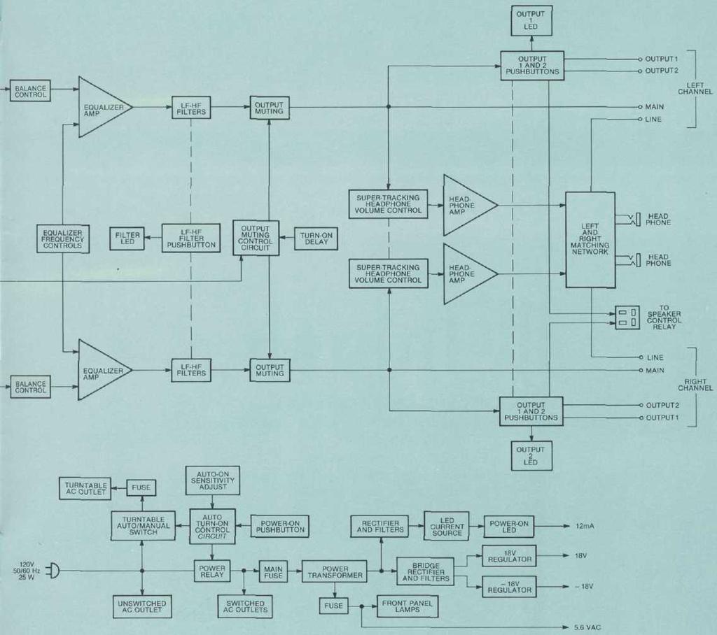
25 PREAMPLIFIER 23

26 MclNTOSH LABORATORY INC. 2 CHAMBERS ST., BINGHAMTON, N.Y The continuous improvement of its products is the policy of Mclntosh Laboratory Incorporated who reserve the right to improve design without notice. Printed in U.S.A BE
27
28
THE MclNTOSH C 504 STEREO PREAMPLIFIER
 THE MclNTOSH C 504 STEREO PREAMPLIFIER Reading Time: 30 Minutes Price: $2.00 VARIOUS REGULATORY AGENCIES REQUIRE THAT WE BRING THE FOLLOWING INFORMATION TO YOUR ATTENTION. PLEASE READ IT CAREFULLY. WARNING:
THE MclNTOSH MQ101 ENVIRONMENTAL EQUALIZER
 THE MclNTOSH MQ101 ENVIRONMENTAL EQUALIZER Price $1.25 Your MQ101 Environmental Equalizer will give you many years of pleasant and satisfactory performance. If you have any questions concerning the operation
MclNTOSH MODEL C-4 and C-4P
 INSTRUCTION MANUAL MclNTOSH MODEL C-4 and C-4P AUDIO COMPENSATORS McINTOSH LABORATORY, INC. 320 Water St. Binghamton, N. Y. U.S.A. - 1 - INSTRUCTION MANUAL McINTOSH MODEL C-4 and C-4P AUDIO COMPENSATORS
IMPORTANT SAFETY INSTRUCTIONS THESE INSTRUCTIONS ARE TO PROTECT YOU AND THE MCINTOSH INSTRUMENT. BE SURE TO FAMILIARIZE YOURSELF WITH THEM.
 IMPORTANT SAFETY INSTRUCTIONS THESE INSTRUCTIONS ARE TO PROTECT YOU AND THE MCINTOSH INSTRUMENT. BE SURE TO FAMILIARIZE YOURSELF WITH THEM. 1. Read all instructions - Read the safety and operating instructions
COHERENCE ONE PREAMPLIFIER
 COHERENCE ONE PREAMPLIFIER OWNER S MANUAL TABLE OF CONTENTS Introduction Features Unpacking Instructions Installation Phono Cartridge Loading Basic Troubleshooting Technical Specifications Introduction
CR10 REMOTE CONTROL SYSTEM
 CR10 REMOTE CONTROL SYSTEM CR10 REMOTE CONTROL SYSTEM IMPORTANT SAFETY INSTRUCTIONS THESE INSTRUCTIONS ARE TO PROTECT YOU AND THE MclNTOSH INSTRUMENT. BE SURE TO FAMILIARIZE YOURSELF WITH THEM 1. Read
Sphinx II. Owner s Manual. Tube Hybrid Integrated Power Amplifier. Rogue Audio, Inc. 3 Marian Lane Brodheadsville, PA Issue date: 08/01/16
 Sphinx II Tube Hybrid Integrated Power Amplifier Owner s Manual Rogue Audio, Inc. 3 Marian Lane Brodheadsville, PA 18322 Issue date: 08/01/16 TABLE OF CONTENTS 1) Introduction 2 2) Unpacking the Sphinx
MODEL PA II-R (1995-MSRP $549.00)
") F O R T H E L O V E O F M U S I C MODEL PA II-R (1995-MSRP $549.00) OWNER'S MANUAL AND INSTALLATION GUIDE INTRODUCTION To aid in the exciting and custom installs which installers are performing all over
F O R T H E L O V E O F M U S I C MODEL PA II-R (1995-MSRP $549.00) OWNER'S MANUAL AND INSTALLATION GUIDE INTRODUCTION To aid in the exciting and custom installs which installers are performing all over
C22 Stereophonic Preamplifier Owner s Manual
 McIntosh Laboratory, Inc. 2 Chambers Street Binghamton, New York C22 Stereophonic Preamplifier Owner s Manual 13903-2699 Phone: 607-723-3512 www.mcintoshlabs.com 2 The lightning flash with arrowhead, within
RoHS. Atma-Sphere Music Preamplifier. model P-2 OWNER'S MANUAL. Please study this document carefully before using equipment
 1742 Selby Av. St. Paul, MN 55104 651 690 2246 atma sphere.com Atma-Sphere Music Preamplifier model P-2 OWNER'S MANUAL Please study this document carefully before using equipment RoHS CONGRATULATIONS!
Technical Specifications
 INSTALLATION SHEET AND OPERATORS MANUAL General Description: The is a mixer/preamplifier that includes 6 channels that each include a microphone input at screw terminals and an aux input at an RCA jack.
Phono Amplifier brinkmann «EDISON» Manual.
 Phono Amplifier brinkmann «EDISON» ----------------------------------------------------------------------------------------------- Manual Preface We congratulate you on the purchase of our «EDISON» phono
CP1 OAD. Owner s Manual. Stereo Control Preamplifier. Ultrafidelity
 OAD Ultrafidelity CP1 Stereo Control Preamplifier Owner s Manual Contents Section Page No. Introduction........................................................................ 1 Warnings.................................................................................
Table of Contents. Read This First.2. Introduction by Jim Fosgate...3. Unpacking..4. Tubes and Tube shield Installation 5. Product Placement...
 Owner s Manual Table of Contents Read This First.2 Introduction by Jim Fosgate...3 Unpacking..4 Tubes and Tube shield Installation 5 Product Placement...6 Connecting your Fosgate Signature..7 Phono stage
CR-6 MIXER USER MANUAL ENGLISH. Order Code: MIXE01
 CR-6 MIXER P R O F E S S I O N A L 1 9 R A C K M I X E R Order Code: MIXE01 w w w. p r o l i g h t. c o. u k USER MANUAL ENGLISH WARNING FOR YOUR OWN SAFETY, PLEASE READ THIS USER MANUAL CAREFULLY BEFORE
110LP MOON Series. Phono Preamplifier. Owner s Manual
 Phono Preamplifier Owner s Manual Owner s Manual I Table of Contents Introduction 4 Unpacking 5 Installation & Placement 5 Circuit Board Layout s 6 Internal Adjustments 7 Rear Panel Connections 8 Operating
J R Sky, Inc. tel: fax:
 STEREO OPTICAL RECORDING SYSTEM N UOPTIX STEREO OPTICAL RECORDING MONITOR LEFT SYSTEM MODE PREVIEW RECORD BIAS RECORD REV SETUP TEST RIGHT INPUT SETUP INPUT BIAS SETUP BIAS INPUT STEREO AUX MONO DIRECT
Low Noise Solid State Phono Preamplifier User's Guide and Operating Information
 Bel Canto Design PHONO 1 Low Noise Solid State Phono Preamplifier User's Guide and Operating Information Bel Canto Design 212 Third Avenue North Suite 345 Minneapolis, MN 55401 Phone: (612) 317.4550 Fax:
508 Phono Preamplifier. Boulder Amplifiers, Inc. 255 S. Taylor Ave. Louisville, CO (303) /1/2018 Rev. 1.
 /1/2018 Rev. 1.") 508 Phono Preamplifier 6/1/2018 Rev. 1.0 P/N: 91053 Boulder Amplifiers, Inc. 255 S. Taylor Ave. Louisville, CO 80027 (303) 449-8220 www.boulderamp.com About About Boulder Amplifiers, Inc. Boulder was founded
508 Phono Preamplifier 6/1/2018 Rev. 1.0 P/N: 91053 Boulder Amplifiers, Inc. 255 S. Taylor Ave. Louisville, CO 80027 (303) 449-8220 www.boulderamp.com About About Boulder Amplifiers, Inc. Boulder was founded
Mapletree Audio Design
 Ultra 4C Preamplifier Mapletree Audio Design Ultra 4C Stereo Phono/Line Preamplifier PS 2D Power Supply User s Manual Rev. Mar. 22, 2019 Mapletree Audio Design R. R. 1, Seeley's Bay, Ontario, Canada, K0H
Various regulation agencies require us to bring the following information to your attention. Please read carefully.
 1 We would like to take this opportunity to thank you for selecting the CDA823 CD-player. We at Copland wish you many enjoyable hours in the company of fine music. Please read this owners manual before
Owner s Manual. Model PH8 Phono Preamplifier
 Owner s Manual Model PH8 Phono Preamplifier 2 Contents Model PH8 Phono Preamplifier Illustrations 4 Preface 5 Warnings 5 Packaging 5 Front Panel Controls 5 6 Remote Control Functions 6 Connections 6 Installation
Owner's Manual. Model PH6 PHONO PREAMPLIFIER.
 Owner's Manual Model PH6 PHONO PREAMPLIFIER 3900 ANNAPOLIS LANE NORTH / PLYMOUTH, MINNESOTA 55447-5447 / PHONE: 763-577-9700 FAX: 763-577-0323 www.audioresearch.com Contents Model PH6 Page No. Preface.......................................................1
ModWright Instruments, Inc. PH 150 Tube Phono Stage Owner s Manual
 ModWright Instruments, Inc. PH 150 Tube Phono Stage Owner s Manual Manufactured by ModWright Instruments, Inc. 21919 399th St., Amboy, WA 98601 USA www.modwright.com 1 CAUTIONS: Do not operate or power
Flat-Bed Module Recorders
 Flat-Bed Module Recorders Model No. 08376-50 08376-55 08376-60 0115-0192 4/28/00 Table of Contents Introduction...3 Power Requirements...3 Chart Paper Installation...3 Pen Installation...5 Grounding...5
MASTR II BASE STATION 12/24V POWER SUPPLY 19A149979P1-120 VOLT/60 Hz 19A149979P2-230 VOLT/50 Hz
 Mobile Communications MASTR II BASE STATION 12/24V POWER SUPPLY 19A149979P1-120 VOLT/60 Hz 19A149979P2-230 VOLT/50 Hz CAUTION THESE SERVICING INSTRUCTIONS ARE FOR USE BY QUALI- FIED PERSONNEL ONLY. TO
bel canto SEP2 Single Ended Triode Tube Preamplifier User's Guide and Operating Information
 bel canto SEP2 Single Ended Triode Tube Preamplifier User's Guide and Operating Information Bel Canto Design 212 Third Avenue North, Suite 274 Minneapolis, MN 55401 USA Phone: 612 317.4550 Fax: 612.359.9358
T L Audio. User Manual C1 VALVE COMPRESSOR. Tony Larking Professional Sales Limited, Letchworth, England.
 T L Audio User Manual C1 VALVE COMPRESSOR Tony Larking Professional Sales Limited, Letchworth, England. Tel: 01462 490600. International +44 1462 490600. Fax: 01462 490700. International +44 1462 490700.
+41 * 2 db. GENERAL The Shure M675 Broadcast Production Master is designed for use in conjunction with a Shure M67 or
 2 2 2 HARTREY AVE., EVANSTON, IL. 6 0 2 0 4 U.S.A. GENERAL The Shure M675 Broadcast Production Master is designed for use in conjunction with a Shure M67 or M67-2E Professional Microphone Mixer, M63 Audio
USER MANUAL GOLDMUND PH3 Phono Preamplifier
 USER MANUAL GOLDMUND PH3 Phono Preamplifier Congratulations. Thank you for purchasing the Goldmund PH3 Phono Preamplifier. You have acquired the best Phono Preamplifier ever made for professional and domestic
music hall pa2.2 INSTRUCTION MANUAL music hall
 music hall pa2.2 INSTRUCTION MANUAL music hall http://www.musichallaudio.com CONGRATULATIONS ON YOUR PURCHASE You have selected an exceptional phono preamplifier. Each component used in the construction
Utility Amplifier GA6A Model
 Utility Amplifier GA6A Model Installation and Use Manual 2004 Bogen Communications, Inc. All rights reserved. Specifications subject to change without notice. 54-5757-03D 1503 NOTICE: Every effort was
Pre1. Balanced Control Preamplifier. User's Guide and Operating Information
 Pre1 Balanced Control Preamplifier User's Guide and Operating Information Bel Canto Design 212 Third Avenue North Suite 345 Minneapolis, MN 55401 Phone: (612) 317.4550 Fax: (612) 359.9358 Email: Info@BelCantoDesign.com
222 HARTREY AVE., EVANSTON, IL U.S.A. AREA CODE 312/ CABLE: SHUREMlCRO. Copyright 1973, Shure Brothers Inc.
 222 HARTREY AVE., EVANSTON, IL. 60204 U.S.A. AREA CODE 312/328-9000 CABLE: SHUREMlCRO General: The Shure Model M63 Audio Master is a unit designed to give maximum flexibility in the control of volume,
TABLE OF CONTENTS. 1) Introduction 2. 2) Unpacking the Ares 2. 3) Installing the Ares in your system 3. 4) Setting the Operational Parameters 4
 Introduction 2. 2) Unpacking the Ares 2. 3) Installing the Ares in your system 3. 4) Setting the Operational Parameters 4") TABLE OF CONTENTS 1) Introduction 2 2) Unpacking the Ares 2 3) Installing the Ares in your system 3 4) Setting the Operational Parameters 4 5) High Output MM/MC Cartridge Setup 6 6) Medium Output Cartridge
TABLE OF CONTENTS 1) Introduction 2 2) Unpacking the Ares 2 3) Installing the Ares in your system 3 4) Setting the Operational Parameters 4 5) High Output MM/MC Cartridge Setup 6 6) Medium Output Cartridge
BP2-MM MM Phono Preamplifier Owner s Manual
 BP2-MM MM Phono Preamplifier Owner s Manual Important Safety Instructions The lightning flash with arrowhead symbol within an equilateral triangle, is intended to alert the user to the presence of un-insulated
USER MANUAL Goldmund PH3.8 Phono Preamplifier
 USER MANUAL Goldmund PH3.8 Phono Preamplifier Congratulations. Thank you for purchasing the Goldmund PH3.8 Phono Preamplifier. You have acquired the best Phono Preamplifier ever made for professional and
OWNER MANUAL PV9 VACUUM TUBE PREAMPLIFIER. conrad-johnson design
 OWNER MANUAL PV9 VACUUM TUBE PREAMPLIFIER conrad-johnson design 703-698-8581 Congratulations on your purchase of the conrad-johnson model PV9 vacuum tube preamplifier. In it, you have acquired one of the
McINTOSH LABORATORY INC., 2 CHAMBERS STREET, BINGHAMTON, NEW YORK 13903
 BEST PERFORMANCE GREATEST MUSICAL SATISFACTION LONGEST PROTECTION HIGHEST RELIABILITY RIGOROUS QUALITY CONTROL METICULOUS MANUFACTURE PAINSTAKING ENGINEERING LONG LIFE STYLING HIGHEST VALUE AT TRADE TIME
CONSONANCE PREAMPLIFIER OWNER S MANUAL
 CONSONANCE PREAMPLIFIER OWNER S MANUAL TABLE OF CONTENTS Introduction Initial Inspection Features Installation Input Impedance Adjustments Preamplifier Internal View Impedance Adjustment Diagram Overall
INTRODUCTION PRODUCT CONCEPT AND DESCRIPTION
 1 INTRODUCTION PRODUCT CONCEPT AND DESCRIPTION The Audio Suite is a mainframe which accepts up to ten modular sections thereby permitting individualized selection of preamplifier features and functions.
THE NOVA PHONOMENA MUSICAL SURROUNDINGS PRESENTS: PHONOGRAPH PREAMPLIFIER OWNER S MANUAL. Musical Surroundings. status
 MUSICAL SURROUNDINGS PRESENTS: THE NOVA PHONOMENA PHONOGRAPH PREAMPLIFIER Musical Surroundings Nova Phonomena Phono Preamplifier status OWNER S MANUAL TABLE OF CONTENTS 1.0) INTRODUCTION..3 2.0) INTERNAL
Operating Manual. Mark Levinson Nº25 Dual Monaural Phono Preamplifier. Madrigal Audio Laboratories, Inc. 1
 Operating Manual Mark Levinson Nº25 Dual Monaural Phono Preamplifier Madrigal Audio Laboratories, Inc. 1 WARNING: TO REDUCE THE RISK OF FIRE OR ELECTRIC SHOCK, DO NOT EXPOSE THIS APPLIANCE TO RAIN OR MOISTURE.
Concert Series ORDERCODE D3470 ORDERCODE D3471 ORDERCODE D3472 D3470 D3471 D3472
 Concert Series ORDERCODE D3470 ORDERCODE D3471 ORDERCODE D3472 D3470 D3471 D3472 Congratulations! You have bought a great, innovative product from DAP Audio. The DAP Audio Concert Series brings excitement
LDG M-7600 External Meter for Icom IC-7600
 M-7600 OPERATIONS MANUAL MANUAL REV A LDG M-7600 External Meter for Icom IC-7600 LDG Electronics 1445 Parran Road St. Leonard MD 20685-2903 USA Phone: 410-586-2177 Fax: 410-586-8475 ldg@ldgelectronics.com
A y r e. K-1x Preamplifier. Owner s Manual
 A y r e K-1x Preamplifier Owner s Manual Table of Contents Welcome to Ayre........................... 2 Installation and Operation......................... 3 Optimizing the Phono Stage........................
INSTRUCTIONS FOR USE Pro-Ject Tube Box DS2
 INSTRUCTIONS FOR USE Pro-Ject Tube Box DS2 Dear music lover, Thank you for purchasing a tube phono preamplifier from Pro-Ject Audio Systems. In order to achieve maximum performance and reliability you
X D M PREAMP MIXER
 User Instructions X D M - 3 5 2 PREAMP MIXER Thank you for purchasing this American DJ product. The XDM-352 is ready to be used, there is no assembly required. Please read the following instructions before
BP2-MM/MC Phono Preamplifier Owner s Manual
 BP2-MM/MC Phono Preamplifier Owner s Manual Important Safety Instructions The lightning flash with arrowhead symbol within an equilateral triangle, is intended to alert the user to the presence of un-insulated
PREAMPLIFIER INTRODUCTION INSTRUCTIONS FOR USE. Thank you for purchasing the Musical Fidelity A3 CR remote control preamplifier.
 INTRODUCTION A3 CR PREAMPLIFIER INSTRUCTIONS FOR USE Thank you for purchasing the Musical Fidelity A3 CR remote control preamplifier. Used properly and carefully, it should give you many years of outstanding
Issue date : 9/11/00. Rogue Audio Tempest Vacuum Tube Integrated Amplifier. Owners Manual. Vacuum Tube Amplifiers
 Issue date : 9/11/00 Rogue Audio Tempest Vacuum Tube Integrated Amplifier Owners Manual Vacuum Tube Amplifiers TABLE OF CONTENTS 1) Introduction 1 2) Setting up your amplifier 1 3) Using an external preamplifier
RMX-44 & RMX-62 MIXING MATRIX. Installation & Operation Manual
 RMX-44 & RMX-6 MIXING MATRIX Installation & Operation Manual TABLE OF CONTENTS RMX-44 & RMX-6 INTRODUCTION... RMX-44 CALLOUTS... RMX-44 BLOCK DIAGRAM... RMX-6 CALLOUTS... 4 RMX-6 BLOCK DIAGRAM... 5 RMX-44
PX-600 Multi-Room Preamp/Controller
 PX-600 Multi-Room Preamp/Controller PX-600 Multi-Room Preamp/Controller Power Tuner CD Tape Aux Video Mute All Off Madrigal Audio Laboratories 2081 South Main Street Middletown, CT 06457 A Harman International
INSTRUCTIONS FOR USE Pro-Ject Tube Box DS2
 INSTRUCTIONS FOR USE Pro-Ject Tube Box DS2 Dear music lover, Thank you for purchasing a tube phono preamplifier from Pro-Ject Audio Systems. In order to achieve maximum performance and reliability you
The Phono Box SUMIKO Fifth Street Berkeley, CA sumikoaudio.com
 The Phono Box SUMIKO 2431 Fifth Street Berkeley, CA 94710 510.843.4500 sumikoaudio.com In the past, all audio system control components (integrated amplifiers, receivers and system pre-amplifiers) had
Phono 2-SB Owner s Manual
 Phono 2-SB Owner s Manual Table of Contents Owner s Manual for the LKV Phono 2-S... 2 1. Installation... 2 2. Unit Configuration... 3 2-A. Overview... 3 Figure 2 Circuit board for one channel.... 4 Figure
DM900 BLUE DOG OWNER S MANUAL
 Professional Disc Jockey Products DM900 BLUE DOG OWNER S MANUAL NUMARK INDUSTRIES 11 Helmsman Road, North Kingstown, RI 02852 http://www.numark.com CONGRATULATIONS! You have purchased the DM900 Blue Dog
PROFESSIONAL 2-CHANNEL MIXER WITH EFFECTS LOOP
 PROFESSIONAL 2-CHANNEL MIXER WITH EFFECTS LOOP QUICKSTART GUIDE ENGLISH ( 1 4 ) GUÍA DE INICIO RÁPIDO ESPAÑOL ( 5 8 ) GUIDE D UTILISATION SIMPLIFIÉ FRANÇAIS ( 9 12 ) GUIDA RAPIDA ITALIANO ( 13 16 ) KURZANLEITUNG
LX20 OPERATORS MANUAL
 LX20 OPERATORS MANUAL CONTENTS SAFETY CONSIDERATIONS page 1 INSTALLATION page 2 INTRODUCTION page 2 FIRST TIME USER page 3 SYSTEM OPERATING LEVELS page 3 FRONT & REAR PANEL LAYOUT page 4 OPERATION page
Operating Manual. Mark Levinson Nº28 Preamplifier. Madrigal Audio Laboratories, Inc. 15
 Operating Manual Mark Levinson Nº28 Preamplifier Madrigal Audio Laboratories, Inc. 15 WARNING: TO REDUCE THE RISK OF FIRE OR ELECTRIC SHOCK, DO NOT EXPOSE THIS APPLIANCE TO RAIN OR MOISTURE. CAUTION RISK
Summit Audio Model TLA-50 Tube Leveling Amplifier
 Summit Audio Model TLA-50 Tube Leveling Amplifier ATTACK FAST SLOW MEDIUM 3 4 5 6 7 TUBE LEVELER 40 60 80 100 VU 3 4 5 6 TLA-50 7 FAST SLOW RELEASE OUTPUT RED. METER 2 1 0 10 GAIN 9 8 7 5 3 1 0 1 2 +3
Owner s Manual. Reference Phono 2 SE Phono Preamplifier
 Owner s Manual Reference Phono 2 SE Phono Preamplifier 2 Contents Model Reference Phono 2 SE Phono Preamplifier Illustrations 4 Preface 5 Warnings 5 Packaging 5 Front Panel Controls 5 6 Remote Control
Overview. A 16 channel frame is shown.
 Overview A 16 channel frame is shown. 22 Mono Input Channel 1 - MIC INPUT The mic input accepts XLR-type connectors and is designed to suit a wide range of BALANCED or UNBALANCED signals. Professional
BEFORE PROCEEDING WITH COMPLETE UNPACKING AND SETUP, CONSULT UNPACKING AND INSPECTION INSTRUCTIONS ON PAGE 8. Model LA 4 COMPRESSOR/LIMITER
 BEFORE PROCEEDING WITH COMPLETE UNPACKING AND SETUP, CONSULT UNPACKING AND INSPECTION INSTRUCTIONS ON PAGE 8 Model LA 4 COMPRESSOR/LIMITER EFFECTIVE WITH SERIAL +3196 United Recording Electronics Industries
Please take a few minutes to read this manual so that you will better understand the featues and capabilities of your MF80. MF80 Owner s Manual 1
 Congratulations on your purchase of the Conrad-Johnson MF80 amplifier. You have acquired one of the finer pieces of musical reproduction equipment available today. The MF80 is the result of over a decade
INSTRUCTIONS FOR USE Pro-Ject Tube Box DS2
 INSTRUCTIONS FOR USE Pro-Ject Tube Box DS2 Dear music lover, Thank you for purchasing this tube phono preamplifier from Pro-Ject Audio Systems. In order to achieve maximum performance and reliability you
TDM 24CX-2 24CX-3 24CX-4 ELECTRONIC CROSSOVER OWNER S MANUAL A U D I O
 TDM A U D I O 24CX-2 24CX-3 24CX-4 ELECTRONIC CROSSOVER OWNER S MANUAL TDM AUDIO INC. 7270 BELLAIRE AVE. NORTH HOLLYWOOD, CA 91605 (818) 765-6200 TDMAUDIO.COM IMPORTANT! *** Read Before Using *** CAUTION:
SW 50. Powered Subwoofer with Built-in Stereo Crossover
 Owner s Manual SW 50 ed Subwoofer with Built-in Stereo Crossover Congratulations on your new purchase and welcome to the AudioSource family of satisfied customers. We trust you will continue to enjoy the
USB Phono Plus. Project Series USER S MANUAL. Audiophile Computer Interface
 USB Phono Plus Audiophile Computer Interface Project Series USER S MANUAL IMPORTANT SAFETY INSTRUCTION READ FIRST This symbol, whenever it appears, alerts you to the presence of uninsulated dangerous voltage
Chameleon Labs Model 7720
 Chameleon Labs Model 7720 Stereo Compressor Owner s Manual 704 228 th Avenue NE, # 826 Sammamish, WA 98074 206-264-7602 www.chameleonlabs.com Revision C - December, 2007 UNPACKING AND INSPECTION Carefully
The performance of a lifetime. Owner s Manual MOON 110LP v2 Phono Preamplifier
 The performance of a lifetime Owner s Manual MOON 110LP v2 Phono Preamplifier MOON by Simaudio simaudio.com Simaudio Ltd 1345 Newton Road, Boucherville, Québec J4B 5H2 CANADA Date Code: 20180831 01 INTRODUCTION
POWERED MIXER MPM 4130 OWNER S MANUAL 4 CHANNEL POWERED MIXER
 POWERED MIXER OWNER S MANUAL MPM 4130 4 CHANNEL POWERED MIXER MPM 4130 4 CHANNEL POWERED MIXER Congratulations on your choice of a powered mixer you have purchased one of the finest powered mixers on the
Ios english manual:ios english manual.qxd 07/08/ :35 Page 1
 Ios english manual:ios english manual.qxd 07/08/2008 10:35 Page 1 Ios english manual:ios english manual.qxd 07/08/2008 10:35 Page 2 Contents Introduction...1 Design Innovation...2-3 Installation...3 Ventilation...4
ANALOG RADIO MIXER. Flexible. Affordable. Built To Last.
 ANALOG RADIO MIXER Flexible. Affordable. Built To Last. Audioarts AIR-4 A N A L O G R A D I O M I X E R At Audioarts, value engineering is straightforward: Define the features our customers require. Design
XO-231 USER S MANUAL. Crossover ENGLISH
 XO-231 Crossover ENGLISH USER S MANUAL IMPORTANT SAFETY INSTRUCTIONS For your own safety you should read this section in full first! Risk of electrical shock! Connect the device only to a properly wired
IMPORTANT SAFETY INSTRUCTIONS
 IMPORTANT SAFETY INSTRUCTIONS When using this electronic device, basic precautions should always be taken, including the following: 1. Read all instructions before using the product. 2. Do not use this
ECP1 MC / MM PHONO PREAMPLIFIER OWNERS MANUAL
 ECP1 MC / MM PHONO PREAMPLIFIER OWNERS MANUAL WARNING: To reduce risk of fire or electric shock, do not expose this appliance to rain or moisture. Do not remove cover. No user serviceable parts inside.
INTEGRATED AMPLIFIER INSTRUCTIONS FOR USE
 INTEGRATED AMPLIFIER INSTRUCTIONS FOR USE Thank you for purchasing the Musical Fidelity Amplifier. Used properly and carefully, it should give you many years of outstanding musical reproduction. The is
INSTRUCTIONS FOR USE Pro-Ject Phono Box DS2 USB
 INSTRUCTIONS FOR USE Pro-Ject Phono Box DS2 USB Dear music lover, thank you for purchasing a Pro-Ject Audio phono amplifier. In order to achieve maximum performance and reliability you should study these
MIC CUE MIC 1 MIC 2 TREBLE BASS MIC1/2 Tone Controls GROUND
 /V-/ Hz Your PYRAMID Series Performance Mixer is a sophisticated control center, perfect for mixing sound from multiple playback sources such as microphones, tuners, CD players, turntables or the audio
Reference 150 LINEAR
 Reference 150 LINEAR USER GUIDE Congratulations on your new CONSONANCE! Our products are based on a simple philosophy: The component shall reproduce the original musical sound, purely and naturally. The
RSL MusicPower Plug-In Installation Manual For Naim NAC 72 Preamp
 RSL MusicPower Plug-In Installation Manual For Naim NAC 72 Preamp (Updated to reflect the adjustable gain output boards Z200V) www.ryansoundlab.com RSL MusicPower Plug-In Installation Manual for Naim NAC
Owner s Manual. Model REFERENCE PHONO 2 P R E A M P L I F I E R
 Owner s Manual Model REFERENCE PHONO 2 P R E A M P L I F I E R 3900 ANNAPOLIS LANE NORTH / PLYMOUTH, MINNESOTA 55447-5447 / PHONE: 763-577-9700 FAX: 763-577-0323 www.audioresearch.com Contents 1 Model
Oxygen ORDERCODE D2150
 Oxygen ORDERCODE D2150 Congratulations! You have bought a great, innovative product from DAP Audio. The DAP Audio Oxygen brings excitement to any venue. Whether you want simple plug-&-play action or a
USER MANUAL. GOLDMUND LOGOS 1N-2N SPEAKER SYSTEM Active Speaker
 USER MANUAL GOLDMUND LOGOS 1N-2N SPEAKER SYSTEM Active Speaker Thank you for purchasing the Goldmund LOGOS 1N-2N SPEAKER SYSTEM The Goldmund Logos line fully incorporates the technological expertise developed
Hi-fi for music lovers...
 REGA RESEARCH LIMITED QUALITY HI-FI DESIGNED AND BUILT IN ENGLAND SINCE 1973. Hi-fi for music lovers... Rega Research Ltd first started making specialist Hi-Fi equipment in 1973. Back then life and the
VK-P10SE WARRANTY REGISTRATION FORM
 VK-P10SE WARRANTY REGISTRATION FORM Unit Serial Number: Customer Name: Address: Date of Purchase: Purchased From: Dealer Name: Address: IMPORTANT NOTE: In order to receive the full five-year product warranty,
Connevans.info. DeafEquipment.co.uk. This product may be purchased from Connevans Limited secure online store at
 Connevans.info Solutions to improve the quality of life Offering you choice Helping you choose This product may be purchased from Connevans Limited secure online store at www.deafequipment.co.uk DeafEquipment.co.uk
LAMM INDUSTRIES, INC.
 LAMM INDUSTRIES, INC. TheLP1Si gnat ur e phono preamplifier LAMM INDUSTRIES, INC. LP1 Signature dual monaural phono preamplifier The dual monaural phono preamplifier model LP1 Signature is the ultimate
Audio Control Center
 Audio Control Center C45 Owner s Manual McIntosh Laboratory, Inc. 2 Chambers Street Binghamton, New York 13903-2699 Phone: 607-723-3512 FAX: 607-724-0549 The lightning flash with arrowhead, within an equilateral
clipping; yellow LED lights when limiting action occurs. Input Section Features
 ELX-1A Rack-Mount Mic/Line Mixer Four inputs, one output in a single rack space Very-highery-high-quality audio performance High reliability Extensive filtering circuitry and shielding protect against
CPH-10 SUBWOOFER OWNERS MANUAL
 CPH-10 SUBWOOFER OWNERS MANUAL www.artcoustic.com Welcome to the world of Artcoustic! Congratulations with your purchase of the Artcoustic CPH-10 Subwoofer. The CPH-10 has an efficient design, producing
SATRI AMPLIFIER AMP-51R. Owner s Manual
 SATRI AMPLIFIER AMP-51R Owner s Manual contents SAFETY INSTRUCTIONS 4 INTRODUCTION 6 OVERVIEW (FRONT PANEL) 8 OVERVIEW (REAR PANEL) 9 OVERVIEW (REMOTE CONTROL) 1 1 OPERATION 12 TROUBLESHOOTING 13 SPECIFICATION
CLASSÉ AUDIO CP-60 REMOTE CONTROL BALANCED PREAMPLIFIER CP-60 OWNER'S MANUAL
 CLASSÉ AUDIO CP-60 REMOTE CONTROL BALANCED PREAMPLIFIER CP-60 OWNER'S MANUAL CLASSÉ DESIGN PHILOSOPHY 1. REPEATED LISTENING DESIGN SESSIONS: Fine tuning of sound by exchanging and mixing of parts (transistors,
MODEL PA-2 AUDIOPATH ENHANCHER (1998-MSRP $399.00)
") F O R T H E L O V E O F M U S I C MODEL PA-2 AUDIOPATH ENHANCHER (1998-MSRP $399.00) OPERATION INSTALLATION MANUAL INTRODUCTION After countless hours of analyzing the performance of existing car audio
F O R T H E L O V E O F M U S I C MODEL PA-2 AUDIOPATH ENHANCHER (1998-MSRP $399.00) OPERATION INSTALLATION MANUAL INTRODUCTION After countless hours of analyzing the performance of existing car audio
GATES AMPLIFIERS. Plug -in. Audio. Solid- Statesman Series HARRIS INTERTYPE CORPORATION. Six Premium Quality Transistorized Products
 Six Premium Quality Transistorized Products 6300 Series Solid- Statesman Audio HARRIS INTERTYPE CORPORATION GATES AMPLIFIERS THE GATES M -6337 TELEVISION AUDIO CON- TROL CONSOLE marks a significant advance
Stereo Cassette Deck
 3-864-650-12(1) Stereo Cassette Deck Operating Instructions TC-TX333 1998 by Sony Corporation WARNING To prevent fire or shock hazard, do not expose the unit to rain or moisture. To avoid electrical shock,
2.0 Wall Mount TV Soundbar Instruction Manual
 8010275 2.0 Wall Mount TV Soundbar Instruction Manual Read all of the instructions before using this soundbar and keep the manual in a safe place for future reference. Safety Information CA UT IO N RISK
FF DUAL FORMAT DJ MIXER USERS MANUAL
 FF - 4000 DUAL FORMAT DJ MIXER USERS MANUAL FF - 4000 INTRODUCTION The features and layout of the FF-4000 were determined in collaboration with leading loudspeaker manufacturers Funktion One, who canvassed
AG 500SC. Owners Manual. Manual Version 1.7
 AG 500SC Owners Manual Manual Version 1.7 1. Table of Contents I. Getting Started page 3. A. Safety Instructions B. Manual Conventions C. Basic Setup D. Protection Modes II. Features and Functions page