StrataSync. DSAM 24 Hour POP Report
|
|
|
- Aileen Young
- 5 years ago
- Views:
Transcription
1 DSAM 24 Hour POP Report Thursday, January 28, 2016 Page 1 of 19
2 Table of Contents Table of Contents... 2 Introduction... 3 POP Test Configuration Location File, Channel Plan, Limit Plan... 4 POP Reports Limits... 6 POP Default Report Limits... 7 POP Reports Units of Measure... 8 Executing POP Tests on DSAM... 9 Generating POP Reports Example POP Report - HTML Example POP Report - Excel APPENDIX A. DSAM 24 Hour POP Report Details When does a 24 hour POP report fails? APPENDIX B. Summary of FCC Proof of Performance Test Overview of FCC Proof of Performance Test Requirements Who must run the tests? When do the tests need to be run? How many channels need to be tested? How are the test channels selected? How many test sites do we need? Where, in the system, are the tests conducted? Are there specified procedures for each test? Where do we send the test results? What happens if we don't pass? Where do I go for more information on Proof Testing? Page 2 of 19
3 Introduction The term Proof of Performance tests may have different interpretations depending on your geographic locality. In North America, Proof of Performance tests can tie directly to testing mandated by the Federal Communications Commission (FCC); however, in other localities Proof of Performance test may simply refer to having the ability to run test over various times and physical constraints such as weather and/or temperature. The DSAM meter can perform Proof of Performance tests immediately or over any set of time intervals that you desire. This is particularly useful when you are running the 24- Hour test required by the FCC in the US and by other international governing bodies. It is a fact that all cable systems need to be able to consistently check measurements in their network during various times and over a wide temperature range. The DSAM together with provides a seamless way for operators to conduct Proof of Performance. This document will provide key step-by-step instructions on setting up to work in conjunction with the DSAM to deliver the Proof of Performance functionality. Page 3 of 19

. 3.")
4 POP Test Configuration Location File, Channel Plan, Limit Plan Proof of Performance testing is configured using. A typical Location File configuration for performing Proof of Performance test is shown below. These same steps are similar when configuring the Channel Plan and Limit Plan configurations. 1. Select Assets -> Manage Templates -> DSAM 2. Select the Location File link in the left panel in the Global Archive section (or you can chose a named Template instead). 3. Create a new Proof Location File by clicking on the + New Location File link. 4. Customize the Proof of Performance configuration file name, Initial Values and/or Field Names. Page 4 of 19


5 5. Save the Location File. 6. On the Global Archive list page, select that Location File, open the Actions dropdown and select Deploy. 7. Select the desired DSAMs to deploy to. Press Next. Confirm your selections and press Deploy. 8. Synchronize selected meters with the Server. Page 5 of 19

6 POP Reports Limits Below are the editable limits, applies these modified limits while performing the DSAM 24 hour POP report. On the top of your browser window, select System Settings. These instructions assume you have permissions to view/edit these settings. From the left panel, select DSAM 24 Hour Report Limits. This page allows a user to edit POP FCC limits that are used in validating POP tests. Click on Done to save changes to any edited fields. To restore default FCC limits, click on Restore To Default button at the top of page followed by click on the Done button to save changes. A description of the Analog Delta Video Offset and Digital Delta Video Offset can be found in Appendix A. Remaining limits that are visible after scrolling: Page 6 of 19
7 POP Default Report Limits Below table lists the default POP limit values used by. Limit Name Limit Value Comment 24 Hour Deviation 8 db Maximum Adjacent Channel 3 db Maximum Analog Delta Video 10 db Analog Delta Video Offset 1 db For bandwidth > 300 MHz, Offset will be added to Maximum Analog Delta Video limit for each additional 100 MHz above 300 MHz Maximum Digital Delta Video 10 db Digital Delta Video Offset 1 db For bandwidth > 300 MHz, Offset will be added to Maximum Analog Delta Video limit for each additional 100 MHz above 300 MHz Minimum Video Level 3 dbmv Video level for analog channels. Minimum Digital Level -10 dbmv Video level for digital/docsis channels. Minimum Standard Video/Aural Carrier 10 db Level Delta Maximum Standard Video/Aural Carrier Level Delta 17 db Page 7 of 19

8 POP Reports Units of Measure Below are the editable units of measure, applies these while creating the DSAM 24 hour POP report. If your user has ever visited the My Preferences -> Measurement Units page and pressed Done, then that data will override the System Settings values. On the top of your browser window, select My Preferences. From the left panel, select Measurement Units. Click on Done to save changes to any edited fields. On the top of your browser window, select System Settings. These instructions assume you have permissions to view/edit these settings. From the left panel, select Measurement Units. Click on Done to save changes to any edited fields. Page 8 of 19


9 Executing POP Tests on DSAM Key steps in running the Proof of Performance test on the DSAM include the following: 1. Press the AutoTest button on the DSAM 2. Scroll down to and select proof of performance 3. Configure the Proof of Performance Test Channel Plan, Limit Plan, Filename to save to, Ambient Temp, etc. Name entered in Filename to save to field will become folder name for the proof of performance files. 4. Configure Proof of Performance Test Scheduling via Scheduled Soft Key Page 9 of 19


10 Meter shuts down until time of Auto Test and wakes itself Input start time, interval, date, etc... 4 sessions over a 24 hour period 5. Input location data (i.e. Location, Location Type, Area, Trunk, AMP ID ) 6. Start Proof of Performance Test 7. Monitor progress and Review Results. Page 10 of 19

11 8. Results are saved in an appropriately named folder as entered in Filename to save to field in step3. 9. Sync the DSAM to the Server to transfer test results to the server Page 11 of 19
 When 1 asset took all 4 POP test data files: i.")

")
12 Generating POP Reports 1) Retrieve the appropriate test data list. This is available in 2 methods: a) When 1 asset took all 4 POP test data files: i. Select Asset -> Asset List from the top menu. ii. Find the DSAM asset that took all of the results iii. Double click that asset row to get the asset details page. iv. In the right panel named Most Recent Test Data, click the link Create DSAM 24 Hour Report b) Otherwise: i. Select Test Data -> Test Data List ii. Under the Asset Type column header, click the empty box and select the DSAM asset type and Apply. Page 12 of 19


13 iii. Under the Data Type column header, click the empty box, type Pro and select the Proof Of Performance data type and click the test data list (Optionally select one of the following instead: TechComplete Home Certification Test, AutoTest - Video Channels or AutoTest Combo). 2) Select exactly 4 files from the test data list by checking the checkbox in the left column of a desired row. Selections can be made on multiple pages. 3) Click the Actions dropdown and select Reports -> DSAM 24 hour report Example POP Report - HTML Page 13 of 19

14 Page 14 of 19
 and then save to the XLS")
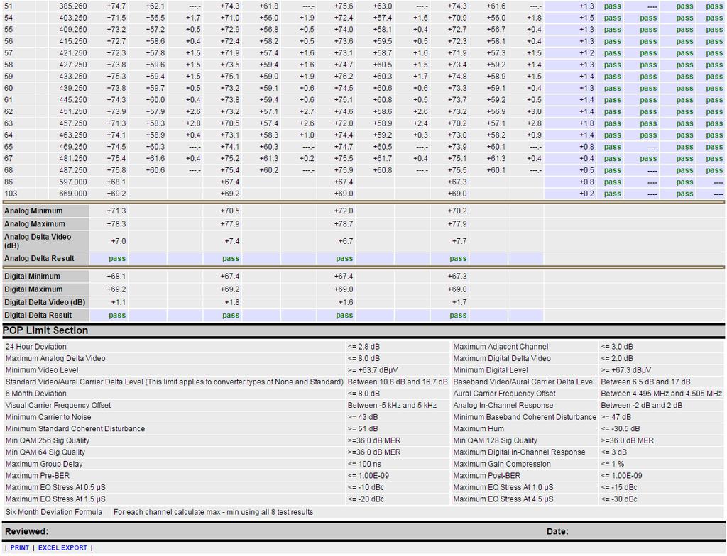
15 Example POP Report - Excel You may also Print or Export-to-Excel the results. When exporting to Excel, it is recommended that you open the results in Excel (which does a conversion from HTML to Excel format) and then save to the XLS or CSV formats as desired. Snapshot of 24 hour POP report in Excel Page 15 of 19
16 APPENDIX A. DSAM 24 Hour POP Report Details When does a 24 hour POP report fails? 24 hour POP report status is fail if: 1. Channel type or frequency does not match among measurements 2. Missing channels in measurement files 3. 4 measurement files are not used 4. If measurements are not with in 6, 12, and 18 hours from the 1st test (plus or minus 1 hour). 5. If 24 hour deviation is not with in 24 Hour Deviation Limit as set in POP Reports Settings page. The default value is 8dB. 6. If Adjacent Visual Signal Level a.k.a Adjacent Channel is not with in Maximum Adjacent Channel limit as set in POP Reports Settings page. The default value is 3dB. This 3dB is applicable for both analog and digital channels. 7. If there are pair of analog (TV or Dual) channels which happen to be with in 6 MHz frequency separation and there is no adjacent channel data measured. 8. If Minimum Visual Signal Level is less than Minimum Video Level Limit as set in POP Reports Settings page. The default value is 3dBmV. 9. If Minimum Digital Level is less than Minimum digital Level Limit as set in POP Reports Settings page. The default value is -10dBmV. 10. If Aural Carrier Level a.k.a V/A Level is not in between MINIMUM STANNDARD VIDEO/AURAL CARRIER LEVEL DELTA and MAXIMUM STANDARD VIDEO/AURAL CARRIER LEVEL DELTA. Default min and max are 10dB and 17 db respectively. 11. If Analog Delta Video is not with in Maximum Analog Delta Video Limit. Maximum Analog Delta Video Limit is calculated as follows using Maximum Analog Delta Video and Analog Delta Video Offset as set in POP reports settings page: If bandwidth > 300MHz then Maximum Analog Delta Video Limit = Maximum Analog Delta Video + Analog Delta Video Offset for each additional 100MHz above 300 MHz. else Maximum Analog Delta Video Limit = Maximum Analog Delta Video The default limit and offset are 10dB and 1dB respectively. 12. If Digital Delta Video is not with in Maximum Digital Delta Video Limit. Maximum Digital Delta Video Limit is calculated as follows using Maximum Digital Delta Video anddigital Delta Video Offset as set in POP reports settings page: If bandwidth > 300MHz then Page 16 of 19
17 Maximum Digital Delta Video Limit = Maximum Digital Delta Video + Digital Delta Video Offset for each additional 100MHz above 300 MHz. else Maximum Digital Delta Video Limit = Maximum Digital Delta Video Note: - If there are no analog channels i.e. only digital channels are present or if there exists analog channels that do not fall in 6 MHz separation with analog channel next to it, and if there is no Adjacent Visual Signal data for any channel then Adjacent Visual Signal status is displayed as No data and it is not taken into consideration for the overall report status calculation. Page 17 of 19
18 APPENDIX B. Summary of FCC Proof of Performance Test Overview of FCC Proof of Performance Test Requirements For details of the Proof of Performance test requirements, refer to the Code of Federal Regulations (CFR) 47, part 76. This book is available from the US Government Printing Office, Mail Stop: SSOP, Washington, DC Many cities in the US have US Government Printing Office stores that sell Government publications directly to the public. Who must run the tests? All systems with 1000 or more subscribers. Smaller systems are required to comply with the Cumulative Leakage Index requirements (including quarterly measurements) but are not normally required to demonstrate proof of performance of the other technical standards. The technical standards are expected to be met by all systems -- but small systems don't need to prove it. When do the tests need to be run? Most tests need to be conducted "at least twice each calendar year (at intervals not to exceed seven months)". The "24 hour" tests "shall be measured and recorded, along with the date and time of the measurement, once every six hours (at intervals of not less than five hours nor more than seven hours after the previous measurement), to include the warmest and the coldest times, during a 24 hour period in January or February and in July or August". The 24 hour test is the only one required during those particular months. The color tests (Chrominance to Luminance Delay Inequality, Differential Gain, and Differential Phase), need to be conducted at least triennially (once every three years). How many channels need to be tested? Many tests are required on all "NTSC or similar video channels" of the system. Other tests are required "a minimum of four (4) channels plus one additional channel for every 100 MHz, or fraction thereof, of cable distribution system upper frequency limit (e.g. 5 channels for cable system upper frequency limit of 101 to 216 MHz; 6 channels for cable television systems with a cable distribution system upper frequency limit of MHz; 7 channels for cable television systems with a cable distribution upper frequency to 300 to 400 MHz, etc.)." All channels are required to meet all of the technical standards. However, for certain of the technical standards, you only need to demonstrate "proof of performance" on a sampling of the channels... How are the test channels selected? "The channels selected must be representative of all the channels within the cable television system." Generally, systems select channels from across the system's spectrum. How many test sites do we need? For systems from 1000 to 12,500 subscribers, tests "... shall include measurements taken at six (6) widely separated points. However, within each cable system, one additional test point shall be added for every additional 12,500 subscribers or fraction thereof (e.g., 7 test points if 12,501 to 25,000 subscribers, etc.). " Also, there must be at least one test point "for each portion of the cable system served by a technically integrated microwave hub". Page 18 of 19
19 Note that this does not mean a test point for each fiber node. Where, in the system, are the tests conducted? Test points "shall be balanced to represent all geographic areas served by the cable system. At least onethird of the test points shall be representative of subscriber terminals most distant from the system input and from each microwave receiver (if microwave transmissions are employed), in terms of cable length". Measurements may be made at convenient monitoring points in the system so long as the data reflects system performance for nearby subscribers. Some measurements (visual signal level and 24 hour tests) are required to be measured "at the end of a 30 meter (100 foot) cable drop that is connected to the subscriber tap,..." Usually, all tests in the field are conducted at the end of a 100 foot drop cable. The 100 foot drop cable simulates typical drops provide to homes. For tests at the output of a set-top converter, connect the converter to the end of the drop cable. Are there specified procedures for each test? In general, no. However, good engineering practices are to be used for all tests. For some measurements, the rules refer to documents such as the "NCTA Recommended Practices for Measurements on Cable Television Systems, 2nd edition, November 1989". A review of that document is an excellent starting point. Of course, measurement equipment and techniques are continually evolving. There is a lot of test equipment available today that make the tests much easier than some of the procedures described in the NCTA documents. Before you decide to use any procedure, you should of course, have a thorough understanding of the test requirements and the algorithms used by your test gear. Do not blindly trust automated test gear simply because it provides "numbers"! Where do we send the test results? Unless told otherwise by the FCC or your franchise authorities, you simply keep the data on file for at least five years. The test data is required to be made available to the FCC or local franchise authorities upon request. What happens if we don't pass? Tests have been run on over 50 systems, many of them multiple times. So far, one system has "passed" all the requirements (it passed one of the two times in which tests were run on it). Given the complexity of today's cable systems, the thousands of mechanical connections involved the number of back hoes and other rodents in our society; something, somewhere, is likely to be broken at any given point in time. The most important thing is to run the tests, find the problems, fix them, and keep a log of the whole process. Of course, carrier leakage problems should be addressed as soon as they are discovered. Authorities tend to frown when aircraft start honing in on bad splices. Where do I go for more information on Proof Testing? Page 19 of 19
Application Note - TechComplete Test Productivity Pack. POP Reporting
 Application Note - TechComplete Test Productivity Pack Page 1 of 61 Table of Contents Introduction... 5 POP Test Configuration... 6 Executing POP Tests on DSAM... 7 Accessing POP Reports... 9 POP Reports
FCC Required Technical Standards for Analog & Digital Signals
 FCC Required Technical Standards for Analog & Digital Signals Robert Schaeffer, President Technology Planners, LLC robert.schaeffer@techplanners.com SCTE IEEE Senior Consultant to NCTC Cable TV Pioneers
Review of the Comcast. Fort Collins Cable System. Technical Characteristics
 Review of the Comcast Fort Collins Cable System Technical Characteristics Prepared by: January 30, 2004 Dick Nielsen Senior Engineer CBG Communications, Inc. Introduction and Background CBG Communications,
SAWM60 AUDIO/VIDEO MODULATOR
 SAWM60 LIMITED WARRANTY Holland Electronics LLC, warrants that the product enclosed with this Limited Warranty statement will conform to the manufacturer s specifications and be free of defects in the
HMA-860H AGILE MODULATOR
 HMA-860H AGILE MODULATOR LIMITED WARRANTY Holland Electronics LLC, warrants that the product enclosed with this Limited Warranty statement will conform to the manufacturer s specifications and be free
MODEL OTM-4870 FREQUENCY AGILE 870MHz F.C.C. COMPATIBLE TELEVISION MODULATOR
 MODEL OTM-4870 FREQUENCY AGILE 870MHz F.C.C. COMPATIBLE TELEVISION MODULATOR USERS MANUAL Phone: (209) 586-1022 (800) 545-1022 Fax: (209) 586-1026 E-Mail: salessupport@olsontech.com 025-000412 Rev. B www.olsontech.com
Getting started with
 Getting started with Electricity consumption monitoring single phase for homes and some smaller light commercial premises OVERVIEW: The OWL Intuition-e electricity monitoring system comprises of three
Updates to the Form and Filing System
 FCC Form 481 Updates to the Form and Filing System Program Year 2016 High Cost Program FCC Form 481 1 Welcome Housekeeping Use the Audio section of your control panel to select an audio source and connect
OTM FREQUENCY AGILE 750MHz F.C.C. COMPATIBLE TELEVISION MODULATOR INSTRUCTION MANUAL
 OTM-4000 FREQUENCY AGILE 750MHz F.C.C. COMPATIBLE TELEVISION MODULATOR INSTRUCTION MANUAL Phone: (209) 586-1022 (800) 545-1022 Fax: (209) 586-1026 E-Mail: salessupport@olsontech.com 025-000331 REV B www.olsontech.com
Autotask Integration Guide
 Autotask Integration Guide Updated May 2015 - i - Welcome to Autotask Why integrate Autotask with efolder? Autotask is all-in-one web-based Professional Services Automation (PSA) software designed to help
Operating Instructions
 Operating Instructions HAEFELY TEST AG KIT Measurement Software Version 1.0 KIT / En Date Version Responsable Changes / Reasons February 2015 1.0 Initial version WARNING Introduction i Before operating
Getting started with
 PART NO. CMA11 3 MADE IN CHINA 1. Measuring CAT II 2. Max. voltage 250V ~ 3. Max. current 71 Amp Getting started with Electricity consumption & Solar PV generation monitoring single phase, for homes fitted
EndNote Essentials. EndNote Overview PC. KUMC Dykes Library
 EndNote Essentials EndNote Overview PC KUMC Dykes Library Table of Contents Uses, downloading and getting assistance... 4 Create an EndNote library... 5 Exporting citations/abstracts from databases and
HyperMedia User Manual
 HyperMedia User Manual Contents V3.5 Chapter 1 : HyperMedia Software Functions... 3 1.1 HyperMedia Introduction... 3 1.2 Main Panel... 3 1.2.2 Information Window... 4 1.2.3 Keypad... 4 1.2.4 Channel Index...
Introduction to EndNote Online
 Introduction to EndNote Online Creating an EndNote Online account Go to EndNote Online. Click on the Access EndNote Online button and, if prompted, enter your Warwick username and password to confirm you
USB Mini Spectrum Analyzer User s Guide TSA5G35
 USB Mini Spectrum Analyzer User s Guide TSA5G35 Triarchy Technologies, Corp. Page 1 of 21 USB Mini Spectrum Analyzer User s Guide Copyright Notice Copyright 2011 Triarchy Technologies, Corp. All rights
Challenges of Launching DOCSIS 3.0 services. (Choice s experience) Installation and configuration
 Installation and configuration") (Choice s experience) Installation and configuration (cont.) (Choice s experience) DOCSIS 3.0 Components M-CMTS deployment DTI Server Edge QAM Modular CMTS I-CMTS Integrated CMTS Integrated DOCSIS 3.0
(Choice s experience) Installation and configuration (cont.) (Choice s experience) DOCSIS 3.0 Components M-CMTS deployment DTI Server Edge QAM Modular CMTS I-CMTS Integrated CMTS Integrated DOCSIS 3.0
SNG-2150C User s Guide
 SNG-2150C User s Guide Avcom of Virginia SNG-2150C User s Guide 7730 Whitepine Road Revision 001 Richmond, VA 23237 USA GENERAL SAFETY If one or more components of your earth station are connected to 120
TSG 90 PATHFINDER NTSC Signal Generator
 Service Manual TSG 90 PATHFINDER NTSC Signal Generator 070-8706-01 Warning The servicing instructions are for use by qualified personnel only. To avoid personal injury, do not perform any servicing unless
Reducing Waste in a Converting Operation Timothy W. Rye P /F
 Reducing Waste in a Converting Operation Timothy W. Rye P. 770.423.0934/F. 770.424.2554 RYECO Incorporated Trye@ryeco.com 810 Pickens Ind. Dr. Marietta, GA 30062 Introduction According to the principles
VISSIM Tutorial. Starting VISSIM and Opening a File CE 474 8/31/06
 VISSIM Tutorial Starting VISSIM and Opening a File Click on the Windows START button, go to the All Programs menu and find the PTV_Vision directory. Start VISSIM by selecting the executable file. The following
ENGINEERING COMMITTEE
 ENGINEERING COMMITTEE Interface Practices Subcommittee SCTE STANDARD SCTE 45 2017 Test Method for Group Delay NOTICE The Society of Cable Telecommunications Engineers (SCTE) Standards and Operational Practices
CI-218 / CI-303 / CI430
 CI-218 / CI-303 / CI430 Network Camera User Manual English AREC Inc. All Rights Reserved 2017. l www.arec.com All information contained in this document is Proprietary Table of Contents 1. Overview 1.1
IP Broadcasting System. User manual
 IP Broadcasting System User manual 1. IP Broadcast System Hardware and Operating System Demands 1.1 Lowest Demands of Computer Hardware I. CPU : Intel Core Quad 3.0GHz II. RAM : 4GB III. Standard sound
0.56" 4 Digital Blue LED Panel Meter (rescalable) User s Guide
 User s Guide") 0.56" 4 Digital Blue LED Panel Meter (rescalable) User s Guide 2004-2009 Sure Electronics Inc. ME-SP037B_Ver1.0 0.56" 4 DIGITAL BLUE LED PANEL METER (RESCALABLE) USER S GUIDE Table of Contents Chapter
0.56" 4 Digital Blue LED Panel Meter (rescalable) User s Guide 2004-2009 Sure Electronics Inc. ME-SP037B_Ver1.0 0.56" 4 DIGITAL BLUE LED PANEL METER (RESCALABLE) USER S GUIDE Table of Contents Chapter
innovative technology to keep you a step ahead Tailored to Simplify Installation and Troubleshooting of RF Signals
 Tailored to Simplify Installation and Troubleshooting of RF Signals Intuitive Color Display with Simple Pass/ Fail Indicators Reduce Installer Entry Errors and Improves Decision Making Autotests Streamline
Installation and Users Guide Addendum. Software Mixer Reference and Application. Macintosh OSX Version
 Installation and Users Guide Addendum Software Mixer eference and Application Macintosh OSX Version ynx Studio Technology Inc. www.lynxstudio.com support@lynxstudio.com Copyright 2004, All ights eserved,
MIGRATION TO FULL DIGITAL CHANNEL LOADING ON A CABLE SYSTEM. Marc Ryba Motorola Broadband Communications Sector
 MIGRATION TO FULL DIGITAL CHANNEL LOADING ON A CABLE SYSTEM Marc Ryba Motorola Broadband Communications Sector ABSTRACT Present day cable systems run a mix of both analog and digital signals. As digital
Analyzing and Saving a Signal
 Analyzing and Saving a Signal Approximate Time You can complete this exercise in approximately 45 minutes. Background LabVIEW includes a set of Express VIs that help you analyze signals. This chapter teaches
innovative technology to keep you a step ahead Tailored to Simplify Installation and Troubleshooting of RF Signals
 Tailored to Simplify Installation and Troubleshooting of RF Signals Intuitive Color Display with Simple Pass/ Fail Indicators Reduce Installer Entry Errors and Improve Decision Making Autotests Streamline
System Requirements SA0314 Spectrum analyzer:
 System Requirements SA0314 Spectrum analyzer: System requirements Windows XP, 7, Vista or 8: 1 GHz or faster 32-bit or 64-bit processor 1 GB RAM 10 MB hard disk space \ 1. Getting Started Insert DVD into
TRAINING DOCUMENT LOS ANGELES UNIFIED SCHOOL DISTRICT (LAUSD) BELL SCHEDULING SYSTEM
 BELL SCHEDULING SYSTEM") Introduction TRAINING DOCUMENT LOS ANGELES UNIFIED SCHOOL DISTRICT (LAUSD) BELL SCHEDULING SYSTEM Prepared by CMCI Version 4 4/23/2017 This document is intended to be a comprehensive guide towards describing
Introduction TRAINING DOCUMENT LOS ANGELES UNIFIED SCHOOL DISTRICT (LAUSD) BELL SCHEDULING SYSTEM Prepared by CMCI Version 4 4/23/2017 This document is intended to be a comprehensive guide towards describing
The Third Generation Mobile Telecommunication Terminal Equipment Technical Specifications
 The Third Generation Mobile Telecommunication Terminal Equipment Technical National Communications Commission CONTENTS 1. FOUNDATION AND SCOPE... 2 1.1 FOUNDATION... 2 1.2 SCOPE... 2 1.3 CONTENTS AND REFERENCE...
VIDEO GRABBER. DisplayPort. User Manual
 VIDEO GRABBER DisplayPort User Manual Version Date Description Author 1.0 2016.03.02 New document MM 1.1 2016.11.02 Revised to match 1.5 device firmware version MM 1.2 2019.11.28 Drawings changes MM 2
Signal Level Meters MS-1000, MS-1200D, MS-1300D, MS-1400
 ACTERNA TEST & MEASUREMENT SOLUTIONS Signal Level Meters MS-1000, MS-1200D, MS-1300D, MS-1400 Key Features Easy-to-use, icon-based interface for all instruments and multilingual firmware options available
SingMai Electronics SM06. Advanced Composite Video Interface: HD-SDI to acvi converter module. User Manual. Revision 0.
 SM06 Advanced Composite Video Interface: HD-SDI to acvi converter module User Manual Revision 0.4 1 st May 2017 Page 1 of 26 Revision History Date Revisions Version 17-07-2016 First Draft. 0.1 28-08-2016
860 DSPi. Multifunction HFC Analyzer. Enhanced Sweep and RSVP Features. DSP Technology Provides Quick, Accurate Measurements
 860 DSPi Multifunction HFC Analyzer Enhanced Sweep and RSVP Features DSP Technology Provides Quick, Accurate Measurements Tests DOCSIS Cable Modem Performance and VoIP Quality Analysis Internet Browser
MAutoPitch. Presets button. Left arrow button. Right arrow button. Randomize button. Save button. Panic button. Settings button
 MAutoPitch Presets button Presets button shows a window with all available presets. A preset can be loaded from the preset window by double-clicking on it, using the arrow buttons or by using a combination
Eagle Business Software
 Rental Table of Contents Introduction... 1 Technical Support... 1 Overview... 2 Getting Started... 5 Inventory Folders for Rental Items... 5 Rental Service Folders... 5 Equipment Inventory Folders...
Screen Shot User Guide Clinical Agency
 Screen Shot User Guide Clinical Agency Table of Contents Page# 2. Step 1 - How to Add Units 3. Step 1 - How to add Unit Locations 4. Step 2 - How to create Unit Schedules Create Unit Availability 5. Step
Model Two and Model Two Lite Signal Level Meters OPERATION MANUAL
 Model Two and Model Two Lite Signal Level Meters OPERATION MANUAL Trilithic Company Profile Trilithic is a privately held manufacturer founded in 1986 as an engineering and assembly company that built
USER GUIDE. Get the most out of your DTC TV service!
 TV USER GUIDE Get the most out of your DTC TV service! 1 800-367-4274 www.dtccom.net TV Customer Care Technical Support 615-529-2955 615-273-8288 Carthage Area Carthage Area 615-588-1277 615-588-1282 www.dtccom.net
X-Sign 2.0 User Manual
 X-Sign 2.0 User Manual Copyright Copyright 2018 by BenQ Corporation. All rights reserved. No part of this publication may be reproduced, transmitted, transcribed, stored in a retrieval system or translated
Synthesized Block Up- and Downconverter
 Visit us at www.w ork-microw ave.de Synthesized Block Up- and Downconverter S, C, X, Ku, K, The satellite up- and downconverters developed and manufactured by WORK Microwave are designed to meet the requirements
USB Mini Spectrum Analyzer User Manual PC program TSA For TSA5G35 TSA4G1 TSA6G1 TSA12G5
 USB Mini Spectrum Analyzer User Manual PC program TSA For TSA5G35 TSA4G1 TSA6G1 TSA12G5 Triarchy Technologies, Corp. Page 1 of 17 USB Mini Spectrum Analyzer User Manual Copyright Notice Copyright 2013
Q-Lab Software. for the 8821Q-R OPERATION MANUAL
 Q-Lab Software for the 8821Q-R OPERATION MANUAL Trilithic Company Profile Trilithic is a privately held manufacturer founded in 1986 as an engineering and assembly company that built and designed customer-directed
Synergy SIS Attendance Administrator Guide
 Synergy SIS Attendance Administrator Guide Edupoint Educational Systems, LLC 1955 South Val Vista Road, Ste 210 Mesa, AZ 85204 Phone (877) 899-9111 Fax (800) 338-7646 Volume 01, Edition 01, Revision 04
ViewCommander- NVR Version 3. User s Guide
 ViewCommander- NVR Version 3 User s Guide The information in this manual is subject to change without notice. Internet Video & Imaging, Inc. assumes no responsibility or liability for any errors, inaccuracies,
innovative technology to keep you a step ahead 24/7 Monitoring Detects Problems Early by Automatically Scanning Levels and other Key Parameters
 24/7 Monitoring Detects Problems Early by Automatically Scanning Levels and other Key Parameters Issues SNMP Traps to Notify User of Problems Ability for Remote Control Lets Users Take a Closer Look Without
9 Analyzing Digital Sources and Cables
 9 Analyzing Digital Sources and Cables Topics in this chapter: Getting started Measuring timing of video signal Testing cables and distribution systems Testing video signal quality from a source Testing
Keysight Method of Implementation (MOI) for VESA DisplayPort (DP) Standard Version 1.3 Cable-Connector Compliance Tests Using E5071C ENA Option TDR
 for VESA DisplayPort (DP) Standard Version 1.3 Cable-Connector Compliance Tests Using E5071C ENA Option TDR") Revision 1.00 February 27, 2015 Keysight Method of Implementation (MOI) for VESA DisplayPort (DP) Standard Version 1.3 Cable-Connector Compliance Tests Using E5071C ENA Option TDR 1 Table of Contents 1.
Revision 1.00 February 27, 2015 Keysight Method of Implementation (MOI) for VESA DisplayPort (DP) Standard Version 1.3 Cable-Connector Compliance Tests Using E5071C ENA Option TDR 1 Table of Contents 1.
Getting Started with the LabVIEW Sound and Vibration Toolkit
 1 Getting Started with the LabVIEW Sound and Vibration Toolkit This tutorial is designed to introduce you to some of the sound and vibration analysis capabilities in the industry-leading software tool
HD-CM HORIZON DIGITAL CABLE METER
 HD-CM OFF! Max RF i/p = +17dBm 75Ω Max AC/DC i/p = 120Vrms MENU INPUT ON HORIZON DIGITAL CABLE METER Horizon Global Electronics Ltd. Unit 3, West Side Flex Meadow Harlow, Essex CM19 5SR Phone: +44(0) 1279
Common Spatial Patterns 3 class BCI V Copyright 2012 g.tec medical engineering GmbH
 g.tec medical engineering GmbH Sierningstrasse 14, A-4521 Schiedlberg Austria - Europe Tel.: (43)-7251-22240-0 Fax: (43)-7251-22240-39 office@gtec.at, http://www.gtec.at Common Spatial Patterns 3 class
Cisco Spectrum Expert Software Overview
 CHAPTER 5 If your computer has an 802.11 interface, it should be enabled in order to detect Wi-Fi devices. If you are connected to an AP or ad-hoc network through the 802.11 interface, you will occasionally
Dual HD input, frame synchronizer, down converter with embedder, de-embedder and CVBS encoder COPYRIGHT 2008 AXON DIGITAL DESIGN BV
 Dual HD input, frame synchronizer, down converter with embedder, de-embedder and CVBS encoder A Synapse product COPYRIGHT 2008 AXON DIGITAL DESIGN BV ALL RIGHTS RESERVED NO PART OF THIS DOCUMENT MAY BE
99 Washington Street Melrose, MA Fax TestEquipmentDepot.com OPERATION MANUAL. The Best Thing on Cable
 99 Washington Street Melrose, MA 02176 Fax 781-665-0780 TestEquipmentDepot.com OPERATION MANUAL The Best Thing on Cable Table of Contents INDEX I General Information Introduction... 3 Features: RSVP 2
Projector Management Application Version 7.00 Instruction Guide
 Projector Management Application Version 7.00 Instruction Guide Contents 1 INTRODUCTION... 4 1.1 OUTLINE... 4 1.2 SYSTEM... 4 2 INSTALLATION... 5 2.1 SYSTEM REQUIREMENTS... 5 2.2 PROJECTOR MANAGEMENT APPLICATION
Radio Thermostat Clock
 Radio Thermostat Clock Installation & User Instructions Part number: ZU0800009 80.10.1375.7_feeling_ks_fer_en.indd 1 18.04.2013 11:25:42 Table of contents Safety instructions... 3 Product details... 4
Dual HD input, frame synchronizer, down converter, embedder, CVBS encoder COPYRIGHT 2008 AXON DIGITAL DESIGN BV ALL RIGHTS RESERVED
 Dual HD input, frame synchronizer, down converter, embedder, CVBS encoder A Synapse product COPYRIGHT 2008 AXON DIGITAL DESIGN BV ALL RIGHTS RESERVED NO PART OF THIS DOCUMENT MAY BE REPRODUCED IN ANY FORM
USB Mini Spectrum Analyzer User Manual TSA Program for PC TSA4G1 TSA6G1 TSA8G1
 USB Mini Spectrum Analyzer User Manual TSA Program for PC TSA4G1 TSA6G1 TSA8G1 Triarchy Technologies Corp. Page 1 of 17 USB Mini Spectrum Analyzer User Manual Copyright Notice Copyright 2013 Triarchy Technologies,
Table of Contents. iii
 Rental Table of Contents Introduction... 1 Technical Support... 1 Overview... 2 Getting Started... 3 Inventory Folders for Rental Items... 3 Rental Service Folders... 3 Equipment Inventory Folders...
Printed Documentation
 Printed Documentation Table of Contents INTRODUCTION... 1 Technical Support... 1 Overview... 2 GETTING STARTED... 3 Inventory Folders for Rental Items... 3 Rental Service Folders... 4 Equipment Inventory
TROUBLESHOOTING DIGITALLY MODULATED SIGNALS, PART 2 By RON HRANAC
 Originally appeared in the July 2006 issue of Communications Technology. TROUBLESHOOTING DIGITALLY MODULATED SIGNALS, PART 2 By RON HRANAC Digitally modulated signals are a fact of life in the modern cable
E X P E R I M E N T 1
 E X P E R I M E N T 1 Getting to Know Data Studio Produced by the Physics Staff at Collin College Copyright Collin College Physics Department. All Rights Reserved. University Physics, Exp 1: Getting to
FREQUENCY CONVERTER. MULTIPLE OUTPUT WIDEBAND Ku AND Ka DOWNCONVERTERS. Narda-MITEQ FEATURES OPTIONS
 MULTIPLE OUTPUT WIDEBAND Ku AND Ka DOWNCONVERTERS FEATURES Small weather resistant enclosure Automatic 5/10 MHz internal/external reference selection 10/100 Base-T Ethernet and RS-485/RS-422 remote control
Viavi T-BERD 5800 CPRI Testing Guide with ALU BBU Emulation
 Viavi T-BERD 5800 CPRI Testing Guide with ALU BBU Emulation Scope Version 4 January 2018 Firmware 26.0.0.6c1973b or Later REQUIRED! This document describes Common Public Radio Interface (CPRI) testing
Calibrating the timecode signal input
 Chapter 5 Calibrating the timecode signal input Computer hardware can introduce an offset between the timecode signal and the video signal, which causes the timecode and video to be offset when they are
FREQUENCY CONVERTER. MULTIPLE WIDEBAND Ku AND Ka UPCONVERTERS. Narda-MITEQ FEATURES OPTIONS
 FREQUENCY CONVERTER MULTIPLE WIDEBAND Ku AND Ka UPCONVERTERS FEATURES Small weather resistant enclosure Automatic 5/10 MHz internal/external reference selection 10/100 Base-T Ethernet and RS-485/RS-422
Please feel free to download the Demo application software from analogarts.com to help you follow this seminar.
 Hello, welcome to Analog Arts spectrum analyzer tutorial. Please feel free to download the Demo application software from analogarts.com to help you follow this seminar. For this presentation, we use a
Ultra-Wideband Scanning Receiver with Signal Activity Detection, Real-Time Recording, IF Playback & Data Analysis Capabilities
 Ultra-Wideband Scanning Receiver RFvision-2 (DTA-95) Ultra-Wideband Scanning Receiver with Signal Activity Detection, Real-Time Recording, IF Playback & Data Analysis Capabilities www.d-ta.com RFvision-2
Model Three Signal Level Meter. Operation Manual
 Model Three Signal Level Meter Operation Manual Trilithic Company Profile Trilithic is a privately held manufacturer founded in 1986 as an engineering and assembly company that built and designed customer-directed
EDL8 Race Dash Manual Engine Management Systems
 Engine Management Systems EDL8 Race Dash Manual Engine Management Systems Page 1 EDL8 Race Dash Page 2 EMS Computers Pty Ltd Unit 9 / 171 Power St Glendenning NSW, 2761 Australia Phone.: +612 9675 1414
OTM-3550-SW FREQUENCY AGILE F.C.C. COMPATIBLE TELEVISION MODULATOR INSTRUCTION MANUAL
 FREQUENCY AGILE F.C.C. COMPATIBLE TELEVISION MODULATOR INSTRUCTION MANUAL Phone: (209) 586-1022 (800) 545-1022 Fax: (209) 586-1026 E-Mail: salessupport@olsontech.com 025-000233 REV E www.olsontech.com
Digital Video Recorder
 Digital Video Recorder Quick Operation Guide UD.6L0202B0067A02 Thank you for purchasing our product. If there is any question or request, please do not hesitate to contact dealer. This manual is applicable
ConeXus Process Guide
 HHAeXchange ConeXus Process Guide Legal The software described in this document is furnished under a license agreement. The software may be used or copied only in accordance with the terms of the agreement.
PYROPTIX TM IMAGE PROCESSING SOFTWARE
 Innovative Technologies for Maximum Efficiency PYROPTIX TM IMAGE PROCESSING SOFTWARE V1.0 SOFTWARE GUIDE 2017 Enertechnix Inc. PyrOptix Image Processing Software v1.0 Section Index 1. Software Overview...
Wilkes Repair: wilkes.net River Street, Wilkesboro, NC COMMUNICATIONS
 1 Wilkes COMMUNICATIONS 336.973.3103 877.973.3104 Repair: 336.973.4000 Email: wilkesinfo@wilkes.net wilkes.net 1400 River Street, Wilkesboro, NC 28697 2 Table of Contents REMOTE CONTROL DIAGRAM 4 PLAYBACK
OTR-3550 FREQUENCY AGILE - F.C.C. COMPATIBLE TELEVISION PROCESSOR INSTRUCTION MANUAL
 OTR-3550 FREQUENCY AGILE - F.C.C. COMPATIBLE TELEVISION PROCESSOR INSTRUCTION MANUAL Phone: (209) 586-1022 (800) 545-1022 Fax: (209) 586-1026 E-Mail: salessupport@olsontech.com 025-000156 REV F www.olsontech.com
Model 7130 HD Downconverter and Distribution Amplifier Data Pack
 Model 7130 HD Downconverter and Distribution Amplifier Data Pack E NSEMBLE D E S I G N S Revision 1.0 SW v1.0 www.ensembledesigns.com 7130-1 Contents MODULE OVERVIEW 3 Audio Handling 3 Control 3 Metadata
WCS-D800 Programming Software for the Icom ID-800
 for the Icom ID-800 Memory Types Memories Limit Memories VFO Call Channels Receive Frequency Name Show Name Rx Memory Channel Functions TX Power Skip Bank Comments The WCS-D800 Programmer is designed to
User Manual K.M.E. Dante Module
 User Manual K.M.E. Dante Module Index 1. General Information regarding the K.M.E. Dante Module... 1 1.1 Stream Processing... 1 1.2 Recommended Setup Method... 1 1.3 Hints about Switches in a Dante network...
Skycoor Manual PEKASAT SE 2016
 Skycoor Manual PEKASAT SE 2016 1 Contents: 1 Introduction... 3 2 Online activation... 4 2.1 Demo... 4 2.2 Full versions... 4 3 General description of common actions... 5 3.1 Start screen... 5 3.2 Database
administration access control A security feature that determines who can edit the configuration settings for a given Transmitter.
 Castanet Glossary access control (on a Transmitter) Various means of controlling who can administer the Transmitter and which users can access channels on it. See administration access control, channel
Multiple Band Outdoor Block Up- and Downconverters
 Multiple Band Outdoor Block Up- and Downconverters Vertical Mount Option RF IF LO Frequency Frequency Frequency Model Band (GHz) (MHz) (GHz) Number Block Upconverters 1 12.75 13.25 0.95 1.45 11.8 UPB2-WS-13.625
5620 SAM SERVICE AWARE MANAGER MPTGS Driver Version Guide
 5620 SAM SERVICE AWARE MANAGER 9500 MPTGS Driver Version 2.1.0 Guide 3HE-10851-AAAB-TQZZA September 2016 5620 SAM Legal notice Nokia is a registered trademark of Nokia Corporation. Other products and company
Dual HD input, frame synchronizer, down converter, embedder, CVBS encoder ALL RIGHTS RESERVED
 Dual HD input, frame synchronizer, down converter, embedder, CVBS encoder A Synapse product COPYRIGHT 2013 AXON DIGITAL DESIGN BV ALL RIGHTS RESERVED NO PART OF THIS DOCUMENT MAY BE REPRODUCED IN ANY FORM
TF5 / TF3 / TF1 DIGITAL MIXING CONSOLE. TF Editor User Guide
 TF5 / TF3 / TF1 DIGITAL MIXING CONSOLE EN Special notices Copyrights of the software and this document are the exclusive property of Yamaha Corporation. Copying or modifying the software or reproduction
C Module Description
 IQMMX -Input Router & ASI Distribution Amplifier C Module Description The IQMMX is an ASI to 1 switch, distribution amplifier and transport stream switcher with up to 8 outputs in double width form or
CA Outbound Dialer Module. Operation Manual v1.1
 CA Outbound Dialer Module Operation Manual v1.1 Poltys, Inc. 3300 N. Main Street, Suite D, Anderson, SC 29621-4128 +1 (864) 642-6103 www.poltys.com 2013, Poltys Inc. All rights reserved. The information
National Park Service Photo. Utah 400 Series 1. Digital Routing Switcher.
 National Park Service Photo Utah 400 Series 1 Digital Routing Switcher Utah Scientific has been involved in the design and manufacture of routing switchers for audio and video signals for over thirty years.
Copyright 2014 ZES ZIMMER Electronic Systems GmbH. LMG600 Series Introduction
 LMG600 Series Introduction ZES ZIMMER The Touchstone in Power Analysis Precision in Power is the guideline of. ZES ZIMMER is a German high-tech company specialized in developing, manufacturing and distribution
ORM0022 EHPC210 Universal Controller Operation Manual Revision 1. EHPC210 Universal Controller. Operation Manual
 ORM0022 EHPC210 Universal Controller Operation Manual Revision 1 EHPC210 Universal Controller Operation Manual Associated Documentation... 4 Electrical Interface... 4 Power Supply... 4 Solenoid Outputs...
SonarWiz Layback - Cable-Out Tutorial
 SonarWiz Layback - Cable-Out Tutorial Revision 6.0,4/30/2015 Chesapeake Technology, Inc. email: support@chesapeaketech.com Main Web site: http://www.chesapeaketech.com Support Web site: http://www.chestech-support.com
Surge-Gap Drop Amplifier 1 GHz with 42/54 MHz Split
 Taps & Passives Surge-Gap Drop Amplifier 1 Gz with 42/54 Mz Split Description As data, advanced video, and voice services are made available over broadband networks, the demand for signal level at the
Tests on 3G-Base Stations to TS with FSIQ and SMIQ
 Products: FSIQ, SMIQ Tests on 3G-Base Stations to TS 25.141 with FSIQ and SMIQ This application note describes how to measure the various WCDMA signals which are used for transmitter tests on FDD base
Call Recorder Pico Manual V2.0 VC2000
 Call Recorder Pico Manual V2.0 VC2000 1. Green LED * 2. Red LED ** 3. Record button 4. Handset out / Line out 5. I II Switch 6. Handset in / Line in 7. USB 8. Speaker / microphone *** *) The green LED
SingMai Electronics SM06. Advanced Composite Video Interface: DVI/HD-SDI to acvi converter module. User Manual. Revision th December 2016
 SM06 Advanced Composite Video Interface: DVI/HD-SDI to acvi converter module User Manual Revision 0.3 30 th December 2016 Page 1 of 23 Revision History Date Revisions Version 17-07-2016 First Draft. 0.1
1:1 and 1:2 Redundant Low-Noise Ka-Band Block Converter Systems
 R Back to Block/Fixed Tuned Converters 1:1 and 1:2 Redundant Low-Noise Ka-Band Block Converter Systems 1:1 1:1 AND 1:2 REDUNDANT LOW- NOISE Ka-BAND BLOCK CONVERTER SYSTEMS Specifications Options 1:1 Diagram
Agilent Technologies. N5106A PXB MIMO Receiver Tester. Error Messages. Agilent Technologies
 Agilent Technologies N5106A PXB MIMO Receiver Tester Messages Agilent Technologies Notices Agilent Technologies, Inc. 2008 2009 No part of this manual may be reproduced in any form or by any means (including