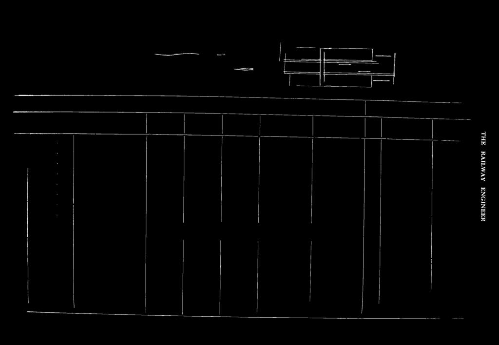
Fig. 2. Typical Point Lay-out.
|
|
|
- Karin Chandler
- 5 years ago
- Views:
Transcription


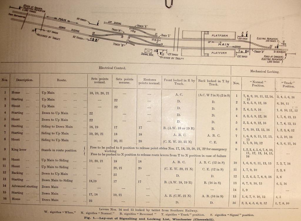
1 route- lever s ig n a l l in g, w in c h e s t e r, g r e a t w e s t e r n r a il w a y. By the Ferreira-Insell Route-Lever Signalling the actuation of one lever simultaneously moves, or holds, all the point levers, and then lowers the requisite signal for a required route. If the files of the Railway Engineer, particularly those for the years immediately prior to and immediately succeeding the year 1910, were searched there would be found described therein several schemes for one lever actuating the points and signals for each route possible at a signal box. All these ideas were of French origin, and it is n ot without interest to know that the first such was designed to meet possible labour troubles. The road, in this, the original, scheme, was made by the turning of a key, so that it pointed to the direction in and Southampton section of the Great Western Railway, and just short of where that line joins, at Shawford Junction, the Southern Railway main line between London and Southampton. The line is single, and Winchester is a passing place, with a siding, mainly for horse-boxes, on the up side, and one, leading to a goods yard, on the down side. The single line thence to Shawford Junction is operated b y the electrical tablet, and we would here remark th at since we visited the installation the tablet has been made to control Fig. 2. Typical Point Lay-out. which the movement was to be made, e.g., if to be to the up line the key had its pointer turned to up line ; if for No. 2 siding then to No. 2 siding. From what we saw of these arrangements at that time they appeared to do their work properly, and their somewhat extensive use, particularly on the Northern and Eastern Railways of France, suggested that they gave satisfaction. The system of route-lever signalling we are now about to describe achieves the purposes mentioned above, but, in general, by means identical to most power-signalling methods. In the type of locking frame and in the signal and point jdeeh&ni*in and actuation there is very little dissimilar from the ail-electric power systems hitherto seen in this country. The Lay-out at W inchester, rig. I u a diagram of Winchester, Cheesehiil, station, Mss it situate at the southern end of the Didcot, Newbury No. 14 starting signal and No. 15 inner home. The section Winchester King s Worthy is operated on the token system. Winchester is not, in our opinion, sufficiently large fully to demonstrate the possibilities of route-lever signalling as compared with the usual power signalling, which latter, as is known, needs much fewer levers than mechanical signalling. A case in our mind, better illustrating these possibilities, is where there are two crossover-junctions. This requires to-day 40 working levers for mechanical operation, would need 28 were it power signalled, but only 17 route levers would be necessary. At Winchester there are 16 levers in the locking frame, which are allotted as lettered in the locking list. Fig. 1. No. 9 is the king lever which is referred to below under the cross heading Individual Operation." In addition to theae 16 levers there are, as also referred to below six slides on the


 and")
 in")

2 t h e r a i l w a y e n g i n e e r. Pig, 3, Interior of Signal-B ox. OW*r Switchboard (left) and Contactor Case (right) in upper part of S ignal-b ox. of Signal-Box. Batteries in tower P***


3 ---- n i 18K *y fkdj TL \ 'i? f i v f t j e : s r $ n n -*> H ONQ,T *2«o 4- T i **0 c.i. Cross Motion. Vj<*. M I % «w h sa *i H *M«0-----f a B J ' ^8 IT V f / I f -1 1 e pj \ **»»! 5]1 L i


4 front of the locking frame for use when points need individually to be operated. These are numbered 17 to 22 inclusive. Method of Operation. If the diagram in Fig. 1 be studied it will be seen that, with the exception of king lever No. 9, all the levers control signals. Each signal has its own route, and when the determined lever is pulled those points which need to Be reversed are, unless already reversed, moved from normal to reverse, and those which have to be normal are, unless already normal, shifted from reverse to normal, and when this is done the signal is put to clear. All point movements are made concurrently and not in series, and current cannot flow to the signal unless and until all the points are in position. It will be convenient to add at this point that should the road concerned be fouled after a signal has been put to clear, or if any of the affected points be damaged, the signal automatically would be put to danger. Track circuit forms a greater basis in route-lever signalling than it usually does in power signalling. At Winchester there are, as indicated in Fig. 1, five track circuits, and they are clear, contacts, operating also at 24 volts, complete a circuit from the 120 volts supply to each of the points concerned, and when the road is made, i.e., all these points in their required normal and reversed position, the check lock that has prevented the lever moving further than the route position is withdrawn and the orange light in the second row appears. The full stroke of the lever now may be completed to lower the signal. When that is correctly done the green light in the third row is switched in and the red light disappears. This sequence is not, however, exactly reversed when a lever is restored, as here is another important feature of the system. The replacement of a lever leaves the points unaltered, i.e., in the position set when the lever was pulled over, unless they act as safety points. If they are, or have connected to them, trap points, e.g., No. 20, No. 17, and the further end of No. 18, they, however, follow the signal. If, on the other hand, they are other than safety points, e.g., Nos. 19, 21 and 22, they remain as they were. For instance, the pulling of either of Nos. 2, 3 or 12 signals would move No. 22 points so as to lie for the up line, but when the signal control the different signals as set out in the locking table given in that illustration. An essential feature calling for early mention is the four rows of lights facing the signalman and placed behind the levers four lights for each lever. When a lever is normal a red light in the uppermost row is in. The second row has green lights, the third orange, and the fourth white. Their purpose will be described directly. Another essential is that, as in most, power systems, the forward and backward strokes are made in two stages. The first forward stage is from the normal position to the route position, and the second 8 from " route to signal. In reversing, the first stage is from signal to track, and then from track to normal. Each midway stage is, as usual, controlled by a check lock. It may also here be observed that only 24 volts is necessary for all controlling purposes; only for the actual operation of the points and signals is power at 120 volts necessary. The contacts for making and breaking the oontrol and operating circuits are carried on slides attaohed to the lever*. VVhen a lever is moved from the normal to the route }M*utMiu, the track circuits oouoerued, operating at 24 volts, cause provided tlu- tracks affected are clear, the respective white light in (he bottom row to be switched iu. If the tracks was put to danger the points would remain lying for the up line. They would thus be in position for any of these three signals again to be used, and so the power that would have been employed to restore and again to reverse the points would be saved. But were No. 4 or No. 5 or No. 16 wanted, the points would respond and lie for the down line. The first movement, in restoring a lever, is from the signal to the track position. This would put the signal to danger, but would leave all the points unaltered, even those acting as traps. When the signal is on the green indication disappears and the red again is illuminated. If the train or vehicle has passed off the track circuits controlling the lever in question the white light also is illuminated and the oheck look is withdrawn. The lever niay then be put from the track to the normal position, and when those points that are, or have, safety points are normal, the white light goes out and, again, only the red is seen. If, however, the train has not left, or the line be otherwise oocupied, the oheok look will not be withdrawn and the lever consequently cannot be moved from track to normal. An intimation that the lever remains locked is indicated by the uonappearanoe of the white light. One result of the track circuits thus holding the levers is that there is no necessity to provide lockiug bars to the facing point plungers.


5 Provision for Individual O peration. There are, necessarily, times, e.g., when points require cleaning, adjusting or repairing, when it is requisite to work a set of points independently of the complete route. For that purpose there are provided the six slides, already mentioned as in the front of the locking frame, which are numbered 17 to 22 inclusive, and connected electrically to the points numbered correspondingly on the diagram, Fig. 1. These slides stand normally in a midway or neutral position and have two indications. When in their normal position green is shown, and, when reversed, orange. These indications are operative at all times, whether the points are controlled by the route levers or arc being individually operated. Those levers coupled to safety points show, however, red when reversed, in order to draw special attention to their position. It is for this individual operation that the king lever is provided. It stands normally in the route position and is locked when there by every other lever in the frame, i.e., every other lever must be normal before No: 9 can be moved from its route position. When pulled to the signal position every other lever in the frame is locked and all the point slides are free.. When the requisite work has been done to the points the slides must be restored to the neutral or normal position in order to replace the king lever and thereby free the route levers. The restoration of the king lever will automatically restore any safety points which may have been reversed during the. manipulation of the point slides. Points other than safety points will, as in the former case, be left as last placed. Should a lever in the frame not get the expected response, say, owing to the track relay failing to pick up, and it cannot be moved from track to normal, this, generally, will be put right by moving the king lever from route to normal and then back to route again. Interlocking. As there are no purely point levers in the frame, all the interlocking is done through the signals. This is a feature that is contrary to the basis of interlocking wherein the greater part of the work is done through the point levers. This necessitates a larger number of locks but, actually, all dead locking is more easily achieved. What must have been troublesome was that the restoration of some signal levers would put certain points into their normal position whilst they were still required to be reversed. For that reason some of the locking does not come into play until the signal lever has been moved back from the signal to the track position. If each lever be traced through the locking list given in Fig. 1, some novel features will be found. The way in which the road is held is very clever. No. 10, for instance, when put to danger, i.e., when it reaches the track position, locks Nos. 1, 7, 8 and 10, and, therefore, none of those signals can be lowered until No. 16 has been put fully to the normal position. The locking frame is of an entirely new design of Siemens Bros. & Go. Ltd. Point Mechanism. Fig. 2 is a reproduction of a photographic view of Nos. 18 and 19 points where the latter becomes the south end facing points of the passing loop. The points and motor mechanisms in the immediate foreground are No. 18; the next motor is coupled to No. 17 trap point, the single switch of which is seen on the extreme right, and the further points are No. 19, to which is coupled the fnrthest motor mechanism. The covers in the four-foot" have been temporarily turned back, also the tops removed from the motor and detector easts. The operation of the points will be better understood from r i f t. which is a copy of a drawing kindly supplied by Siemens Bros, and which may be imagined as illustrating No. 19 petals. The motor is contained in the case a, and when the points are bolted, as in the. case illustrated, the first movement withdraws the plunger b. By the time this is done the crank in the motor and coupled to the rod c becomes engaged, and the points are moved over. This completed, the crank comes to rest, but the motor continues to run, and the toggle, seen in Fig. 2, on the upper side of the wheel, having reached a central position, causes, when further actuated, a movement in the opposite direction to be given to the plunger so that the points arc again bolted, but in their new position. Each of the two point switches is detected electrically in the case d ; rod (ll is from the further switch, rod d1from the nearer switch and rod d* from the plunger. The detection of plungers is now a very important matter, and in Fig. 0 may be seen details of the new plunger adopted by the Great Western Railway. The plunger blade b moves'in the casting e through the slot e1of which the stretcher rod of the points passes at right angles to the plunger. The blade is bevelled at b1 as shown, and this acts upon the cross motion f- as seen clearer in the drawing, Fig. 6 lying in the recess in the casting. To the cross motion is attached at / ' the rod d2 leading to the detector box. The safety spring seen, with its cover removed, in Fig. 2, deserves some mention, and details thereof are therefore given in Fig. 7. It is provided by the Great Western Railway to obviate damage to the switches and to the point mechanism when points are run through trailing from the direction for which they are not set. The rod to the points c in Fig. 5 is in two parts. The part nearer the switches ends in blade A and that nearer the motor in blade B. In the end of each blade are two cotters, and between each pair of cotters is a spiral spring. The spring is sufficiently rigid that when blade B is moved it will carry blade A with it, but sufficiently clastic to yield to such undue pressure that would come from blade A being forced in or pulled out, as would happen when the points were run through. After the pressure had passed the spring would return the switches to their former position. The blades are slotted so that, if compressed, they may dovetail. A pressure of 5 cwt. is necessary to compress the spring 9 in. The system has been invented and patented by Mr. L. M. G. Ferreira, Assoc.M.Inst.C.E., chief of the railway signal department of Siemens Bros. & Co., Caxton House, S.W.l, and Mr. R. J. Insell, Chief Assistant to the Signal and Telegraph Engineer, Great Western Railway. We are, as already said, indebted to Siemens Bros, for the drawing from which Fig. 5 has been prepared. For the remainder, and for the opportunity to inspect the work, we have to thank Mr. A. T. Blackali, M.Inst.C.E., Signal and Telegraph Engineer, Great Western Railway. R A IL R E C L A M A T IO N IN T H E U N IT E D S T A T E S. Recognising that rail wear takes place more rapidly at the ends and necessitating renewal long before the main portion of the rail shows signs of wear, the Illinois Central Railway have introduced the practice of cutting off the damaged ends and relaying the rails, which are then in good condition. According to our American contemporary, the Engineering News-Record, two plants for cropping and drilling rails battered or worn at the ends are operated by the railway, one of which is portable. The permanent plant is situated at Centralia, 111., and is equipped with electrically-driven machinery. Some 22 men are employed, giving an average output of 10,OCX) ft. of rail drilled and sawn per eight-hour day. The portable plant is moved from point to point where worn rails are stacked when relaying is to take place in the same district, thus avoiding long haul of the rails to the permanent plant. A standard crop of 12 or 18 in. at each end ia adopted, and rails from a particular track and therefore of uniform wear are kept together to facilitate matching of joints when relaying.


6 THE RAILWAY ENGINEER
Transportation Engineering - II Dr. Rajat Rastogi Department of Civil Engineering Indian Institute of Technology - Roorkee
 Transportation Engineering - II Dr. Rajat Rastogi Department of Civil Engineering Indian Institute of Technology - Roorkee Lecture 25 Interlocking of Track Dear students, welcome you back to the lecture
2 Layout and Use of Signals
 Issued May 2 Layout and Use of Signals 2. General Signals are provided to control the movement of trains and to inform the driver whether it is safe to proceed. Their location is dictated largely by the
Ground Frames and Shunters Releases
 Ground Frames and Shunters Synopsis This document mandates the interface requirements for ground frames and shunters releases that may be operated by railway undertaking personnel. Copyright in the s is
Sunbury SUNBURY (23 3/4 MILES)
") Sunbury SUNBURY (23 3/4 MILES) Sunbury was the terminus of the first country section of the Victorian Railways to be opened in 1859 and the line was extended to the north two years later. The curious three
Sunbury SUNBURY (23 3/4 MILES) Sunbury was the terminus of the first country section of the Victorian Railways to be opened in 1859 and the line was extended to the north two years later. The curious three
Fixed Signals - Rules 1 to 23
 Applicability VIC Publication Requirement External Only Document Status Issue/Revision # Effective from 1 07 August 2011 0 04 October 2015 1 01 July 2018 Australian Rail Track Corporation Limited (ARTC)
SIGNALING PRACTICES ON PROTOTYPE AND MODEL RAILROADS
 SIGNALING PRACTICES ON PROTOTYPE AND MODEL RAILROADS Bill Ataras September 30, 2013 PROTOTYPE SIGNALING PRACTICE 1. Many different types of signals A. Block signals B. Interlocking signals C. Whistles
BURNLEY GROUP OPERATING PROCEDURES
 The Operating Procedures contained in this document titled Burnley Group Operating Procedures refer to the area bounded by Richmond, Glen Waverley, Alamein, Belgrave & Lilydale. Approval Amendment Record
Kyneton KYNETON (40 MILES)
") Kyneton KYNETON (40 MILES) Kyneton was the terminus of the third section; the line was opened to Kyneton in April 1862 and extended to Castlemaine in October 1862. Kyneton had a small goods yard to serve
Kyneton KYNETON (40 MILES) Kyneton was the terminus of the third section; the line was opened to Kyneton in April 1862 and extended to Castlemaine in October 1862. Kyneton had a small goods yard to serve
PRIVATE and not for Publication NOTICE No. S.2649 BRITISH RAILWAYS. (WESTERN REGION) (For the use of employees only) Notice to Trainmen, etc.
 (For the use of employees only) Notice to Trainmen, etc.") PRIVATE and not for Publication NOTICE No. S.2649 BRITISH RAILWAYS (WESTERN REGION) (For the use of employees only) Notice to Trainmen, etc. MULTIPLE ASPECT SIGNALLING BRISTOL (Stage 3.C.-Bristol Temple
PRIVATE and not for Publication NOTICE No. S.2649 BRITISH RAILWAYS (WESTERN REGION) (For the use of employees only) Notice to Trainmen, etc. MULTIPLE ASPECT SIGNALLING BRISTOL (Stage 3.C.-Bristol Temple
Transportation Engineering -II Dr. Rajat Rastogi Department of Civil Engineering Indian Institute of Technology - Roorkee
 Transportation Engineering -II Dr. Rajat Rastogi Department of Civil Engineering Indian Institute of Technology - Roorkee Lecture - 22 Signals part - 1 Dear students, I welcome you back to the lecture
The perforator machine below shows in the front, the three keys. The left is for dots, the centre is for space and the right is for dashes.
 MACHINE TELEGRAPHY SYSTEMS USED IN AUSTRALIA By Ron McMullen former Telegraphist, Telegraph Supervisor, Instructor, Senior Postal Clerk and Postmaster in the former Australian P.M.G. Department. The Wheatstone
British Signalling What the driver sees
 Railway Technical Website Background Paper No. 1 One of a series of papers originally published as pages on RTWP and updated for RTW. Introduction British Signalling What the driver sees by Piers Connor
Azatrax Model Railroad Track Signal Control - Single Track
 Installation Guide Azatrax Model Railroad Track Signal Control - Single Track TS2 What it is: The TS2 operates one or two trackside block signals (one in each direction) on one track to simulate the block
'7%/2a. Feb. 10, F. G. CREED 1,792,283 TELEGRAPH RECEIVING APPARATUS FOR PRODUCING PUNCHED TAPE FIG. Filed May 14, Sheets-Sheet l
 Feb. 10, 1931. F. G. CREED 1,792,283 TELEGRAPH RECEIVING APPARATUS FOR PRODUCING PUNCHED TAPE Filed May 14, 1930 5 Sheets-Sheet l FIG. INVENTOR FREDERICK. G. CREED '7%/2a ATTORNEY Feb. 10, 1931. F, G,
GAUGEMASTER PRODIGY EXPRESS
 GAUGEMASTER PRODIGY EXPRESS DCC01 USER MANUAL Version 1.2 2014 1 T A B L E O F C O N T E N T S 1 Getting Started Introduction Specifications and Features Quick Start Connecting to Your Layout Running a
Network Safeworking Rules and Procedures
 Network Safeworking Rules and Procedures Fixed Signals Rule Number: 6005 Version 1.0, 31 March 2016 Fixed Signals Rule Number: 6005 Document Control Identification Document title Number Version Date 6005
Withdrawn Document. Title of Rule Book SECTION N SINGLE LINE WORKING. Page Date Index
 Uncontrolled Railway When Group Printed Standard Title of Rule Book : GO/RT3000 : Master SECTION N SINGLE LINE WORKING Page Date Index Page No. Latest Issue N.1/N.2 December 2002 N.3/N.4 December 2002
INTRODUCTION OF COLOUR LIGHT SIGNALS AND NEW SIGNAL BOX AT MAIDSTONE EAST. On SUNDAY, 8th APRIL, 1962
 Signal Instruction No. 21 S.E.D. SOUTHERN REGION-SOUTH EASTERN DIVISION Instructions to all concerned as to INTRODUCTION OF COLOUR LIGHT SIGNALS AND NEW SIGNAL BOX AT MAIDSTONE EAST (in place of certain
Layout Design For Signaling
 Layout Design For Signaling 2014, Rodney Black h t t p : / / h o m e.c o mca st.n e t / ~ kb 0o ys June 29, 2014 7/5/2014 1 Download 7/5/2014 Layout Design for Signaling 2 Outline 1. Why Signal a Layout
5374 Series Air Activated Tube Tester (For testing straight-through exchanger without removing both heads.)
") TM-73 July 15, 2004 Elliott offers a complete line of precision tube tools, including: tube expanders Boiler Expanders Heat Exchanger Expanders Condenser Expanders Refinery Expanders tube rolling motors
TM-73 July 15, 2004 Elliott offers a complete line of precision tube tools, including: tube expanders Boiler Expanders Heat Exchanger Expanders Condenser Expanders Refinery Expanders tube rolling motors
Handbook 8. Handbook 8. IWA, COSS or PC blocking a line. GE/RT8000/HB8 Rule Book
 GE/RT8000/HB8 Rule Book Handbook 8 IWA, COSS or PC blocking a line Handbook 8 Issue 1 Valid from December 2010 Published by: RSSB Block 2 Angel Square 1 Torrens Street London EC1V 1NY. Contents approved
Handbook 8. Issue 6. IWA, COSS or PC blocking a line. GERT8000-HB8 Rule Book. September 2017 Comes into force 02 December 2017
 GERT8000-HB8 Rule Book IWA, COSS or PC blocking a line Issue 6 September 2017 Comes into force 02 December 2017 Handbook 8 Uncontrolled when printed Published by: RSSB The authoritative version of this
Aerial Cable Installation Best Practices
 Aerial Cable Installation Best Practices Panduit Corp. 2007 BEST PRACTICES Table of Contents 1.0 General... 3 2.0 Introduction... 3 3.0 Precautions... 4 4.0 Pre-survey... 5 5.0 Materials and Equipment...
Everybody has seen Telechron clocks and even. US Navy Warren Telechron Clock System. by Robert Simon (CA)
") Figure 1. Front view of clock with 8'' dial in heavy, perhaps fully, waterproof Phenolic US Navy specification plastic case. US Navy Warren Telechron Clock System by Robert Simon (CA) Everybody has seen
Figure 1. Front view of clock with 8'' dial in heavy, perhaps fully, waterproof Phenolic US Navy specification plastic case. US Navy Warren Telechron Clock System by Robert Simon (CA) Everybody has seen
UltraTwist. Product Description. Instruction Guide
 UltraTwist Instruction Guide English 7EN111103-01 2009-07-06 Applies to the following models: UltraTwist Slim Prod. No. 3126045 UltraTwist Wide Prod. No. 3126047 UltraTwist Slim UltraTwist Wide Product
Cable Testing Basic guide to cable testing for newly qualified SMTH staff or trainees.
 Cable Testing Basic guide to cable testing for newly qualified SMTH staff or trainees. This is for information only. The SMTH MUST ALWAYS BE FOLLOWED AT ALL TIMES. F. M. Spowart June 2018 v1 Cable Testing
Layout Design For Signaling
 Layout Design For Signaling 2 0 1 5, Ro d n e y B l a c k N o v e m b e r 1 5, 2 0 1 5 11/15/2015 1 Download This Presentation 11/15/2015 Layout Design for Signaling 2 Outline 1. Why Signal a Layout 2.
Aspect 2 Circuit Digital Scene Control
 Aspect 2 Circuit Digital Scene Control S p e c i f i c a t i o n 2 circuits of trailing edge dimming 500W total between the two circuits Both circuits feature independent overload, short-circuit and open-circuit
Running Signals ANSG 600. Applicability. Publication Requirement. Document Status NSW SMS. External Only October 2015.
 Applicability NSW SMS Publication Requirement External Only Document Status Issue/Revision # Effective from 3.0 11 October 2015 Australian Rail Track Corporation Limited (ARTC) Disclaimer This document
DLP200M 2 Relay Module for Heating and Cooling Plants
 Product Sheet TH6.24 Thermostat Type DLP200M DLP200M 2 Relay Module for Heating and Cooling Plants The DLP 200 M is a relay module for activation of loads (namely thermal actuators or circulators) in wireless
FORENSIC CASEBOOK. By Bob Huddleston, Eastman Chemical Co. One of the most common. reasons for marriage failure
 The Case of the Energized Cable Cutting Incident How miscommunication leads to an electrical helper slicing through live 13.8kV cable and miraculously walking away to tell about it By Bob Huddleston, Eastman
PSC300 Operation Manual
 PSC300 Operation Manual Version 9.10 General information Prior to any attempt to operate this Columbia PSC 300, operator should read and understand the complete operation of the cubing system. It is very
( InfoSystems Translation )
") IN THE UNITED STATES DISTRICT COURT FOR THE WESTERN DISTRICT OF TEXAS WACO DIVISION RETROLED COMPONENTS, LLC, Plaintiff, v. PRINCIPAL LIGHTING GROUP, LLC Defendant. Civil Case No. 6:18-cv-55-ADA JURY TRIAL
IN THE UNITED STATES DISTRICT COURT FOR THE WESTERN DISTRICT OF TEXAS WACO DIVISION RETROLED COMPONENTS, LLC, Plaintiff, v. PRINCIPAL LIGHTING GROUP, LLC Defendant. Civil Case No. 6:18-cv-55-ADA JURY TRIAL
DLP600M 6+1 Relay Module for Heating and Cooling Plants
 Product Sheet TH6.25 Thermostat Type DLP600M DLP600M 6+1 Relay Module for Heating and Cooling Plants The DLP 600 M is a relay module for activation of loads (namely thermal actuators or circulators) in
"Sophisticated Model Railroad Electronics"
 LOGIC RAIL TM "Sophisticated Model Railroad Electronics" TECHNOLOGIES 21175 Tomball Pkwy Phone: (281) 251-5813 Suite 287 email: info@logicrailtech.com Houston, TX 77070 http://www.logicrailtech.com Block
Scan-Light Supplement. Fitting instructions and hardware details For Mitsubishi MH105AG and MH216CG scanners
 Scan-Light Supplement Fitting instructions and hardware details For Mitsubishi MH105AG and MH216CG scanners Contents Contents Fitting instructions and hardware details... 1 For Mitsubishi MH105AG and MH216CG
Installation Manual Original Instructions - IW4001
 Installation Manual Original Instructions - IW4001 Installation Manual 1 General Operator and Supervisor Information Signal Word Definition Signal Word Panel Table of Contents Operator and Supervisor Information
Fully ly Automaticti. Motorised Satellite t TV System. User s manual REV
 REV. 1.0 Fully ly Automaticti Motorised Satellite t TV System User s manual Customer Help Line: 1300 139 255 Support Email: support@satkingpromax.com.au Website: www.satkingpromax.com.au www.satkingpromax.com.au
Manual Addendum For Rerun V1.1 software 12/12/2006, RERUN-A = Serial #06A068, RERUN-P = Serial #06A031
 Manual Addendum For Rerun V1.1 software 12/12/2006, RERUN-A = Serial #06A068, RERUN-P = Serial #06A031 The Rerun product manual was written for V1.0 software. The new release, V1.1, adds a number of new
Caution. Hanging the Screen:
 Installation Instructions for Laminar and Laminar XL Projection Screens Caution 1. Read Instructions through completely before proceeding; keep them for future reference. Follow these instructions carefully.
DAAB DB409 INSTRUCTION MANUAL FOR THE VFD-EL FREQUENCY CONVERTER. For the DAAB EP104 automatic control system with software version 4.
 DAAB DB409 INSTRUCTION MANUAL FOR THE VFD-EL FREQUENCY CONVERTER For the DAAB EP104 automatic control system with software version 4.07 Revision: 12 FAAC Nordic AB BOX 125, SE-284 22 PERSTORP SWEDEN, +46
"Sophisticated Model Railroad Electronics"
 LOGIC RAIL TM "Sophisticated Model Railroad Electronics" TECHNOLOGIES 21175 Tomball Pkwy Phone: (281) 251-5813 Suite 287 email: info@logicrailtech.com Houston, TX 77070 http://www.logicrailtech.com Block
POINTS POSITION INDICATOR PPI4
 POINTS POSITION INDICATOR PPI4 Monitors the brief positive operating voltage across points motors when they are switched Lights a corresponding led on a control panel to show the last operation of each
CENTRIFAN IN-LINE CENTRIFUGAL FAN
 CENTRIFAN IN-LINE CENTRIFUGAL FAN The Peerless Electric Centrifan represents the latest development in the fan and blower industry. Incorporating the tried and proven, highly efficient Peerless wheel in
VISSIM TUTORIALS This document includes tutorials that provide help in using VISSIM to accomplish the six tasks listed in the table below.
 VISSIM TUTORIALS This document includes tutorials that provide help in using VISSIM to accomplish the six tasks listed in the table below. Number Title Page Number 1 Adding actuated signal control to an
RERUN ARCHITECTURAL DMX512 RECORDER OWNERS MANUAL
 RERUN ARCHITECTURAL DMX512 RECORDER MODEL RERUN-A OWNERS MANUAL Doug Fleenor Design 396 Corbett Canyon Road Arroyo Grande, CA 93420 (805) 481-9599 Software Version 1.0 Manual Revision 0 Serial #069177
M SERIES DISPENSER M SERIES DISPENSER
 M SERIES DISPENSER PART NUMBER 5006621 M SERIES DISPENSER M SERIES DISPENSER... M - 1 M15 TOP EXPLODED VIEW... M - 2 M15 TOP PARTS LIST... M - 3 M15 BASE EXPLODED VIEW... M - 4 M15 BASE PARTS LIST... M
Site Installation Model MP-8433
 Site Installation Model MP- Rev. //0 SCOREBOARD SITE INSTALLATION INSTRUCTIONS CAUTION: All American Scoreboards (AAS) recommends the sign be installed by a licensed contractor, and must meet all local
Site Installation Model MP-8424
 Site Installation Model MP- Rev. //0 SCOREBOARD SITE INSTALLATION INSTRUCTIONS CAUTION: All American Scoreboards (AAS) recommends the sign be installed by a licensed contractor, and must meet all local
C 303W-RF Tri-element Array Microphone Instructions
 C 303W-RF Tri-element Array Microphone Instructions C 303W-RF Installation Instructions Packaging C 303W microphone Enclosure with 2.5 Metre (8ft) cae Link cable Cable gland It may be easier to remove
Photovoltaic Module Installation Manual (IEC)
") Phono Solar Technology Co., Ltd. Add: No. 1 Xinghuo Rd., Nanjing Hi-tech Zone, Nanjing, China Tel: +86 25 5863 8000 Fax: +86 25 5863 8009 E-mail: support@phonosolar.com Website: www.phonosolar.com PHONO
Phono Solar Technology Co., Ltd. Add: No. 1 Xinghuo Rd., Nanjing Hi-tech Zone, Nanjing, China Tel: +86 25 5863 8000 Fax: +86 25 5863 8009 E-mail: support@phonosolar.com Website: www.phonosolar.com PHONO
(12) Patent Application Publication (10) Pub. No.: US 2013/ A1
 Patent Application Publication (10) Pub. No.: US 2013/ A1") (19) United States US 2013 0100156A1 (12) Patent Application Publication (10) Pub. No.: US 2013/0100156A1 JANG et al. (43) Pub. Date: Apr. 25, 2013 (54) PORTABLE TERMINAL CAPABLE OF (30) Foreign Application
(19) United States US 2013 0100156A1 (12) Patent Application Publication (10) Pub. No.: US 2013/0100156A1 JANG et al. (43) Pub. Date: Apr. 25, 2013 (54) PORTABLE TERMINAL CAPABLE OF (30) Foreign Application
COLOUR CHANGING USB LAMP KIT
 TEACHING RESOURCES SCHEMES OF WORK DEVELOPING A SPECIFICATION COMPONENT FACTSHEETS HOW TO SOLDER GUIDE SEE AMAZING LIGHTING EFFECTS WITH THIS COLOUR CHANGING USB LAMP KIT Version 2.1 Index of Sheets TEACHING
ELECTRONIC GAME KIT ESSENTIAL INFORMATION. Version 2.0 BUILD YOUR OWN MEMORY & REACTIONS
 ESSENTIAL INFORMATION BUILD INSTRUCTIONS CHECKING YOUR PCB & FAULT-FINDING MECHANICAL DETAILS HOW THE KIT WORKS BUILD YOUR OWN MEMORY & REACTIONS ELECTRONIC GAME KIT Version 2.0 Build Instructions Before
1.0 DESCRIPTION. This specification covers roll-up signs to be used in temporary traffic control zones.
 (Page 1 of 10) ROLL-UP SIGNS (MGS-04-01O) 1.0 DESCRIPTION. This specification covers roll-up signs to be used in temporary traffic control zones. 2.0 MATERIAL. 2.1 SIGNS AND OVERLAYS. 2.1.1 SUBSTRATES.
WIRING INSTRUCTIONS CROP-LINK Drip Installation
 WIRING INSTRUCTIONS 2011-14 CROP-LINK Drip Installation Items Covered In This Manual: Page 1: Crop Link Device Overview Page 2-3: Sensor Connections Page 4: Power and Relay Wiring Page 5-6: Specs and Warranty
The Joys of Life Model Railway Club OPERATING THE RAILWAY. Not To Be Taken Away
 The Joys of Life Model Railway Club OPERATING THE RAILWAY Not To Be Taken Away Operating the Joys of Life Railway Will High 1. Introduction The Joys of Life Railway is a 600 yard long, 5in gauge ground
-164- Agreement with Gold and Stock Telegraph Co. January-June
 -164- Agreement with Gold and Stock Telegraph Co. [New York,] May 26, 1871* Agreement, made this Twenty sixth 26th b day of May 1871 by and between Thomas A. Edison of Newark, State of New Jersey, Inventor
1-Touch Vibratory Sieve Shaker SS-10
 1-Touch Vibratory Sieve Shaker SS-10 Safety Instructions WARNING!! This machine operates on electric current. Improper operation could result in electrical shock, electrocution, or an explosion! 1. ALWAYS
Lineside Signal Aspect and Indication Requirements
 Lineside Signal Aspect and Indication Requirements Synopsis This document mandates the appearance of lineside signalling system displays and the information they convey. This document contains one or more
Identification - electrical services
 Identification - electrical services Aesthetic All live phase cable sheathing to be brown coloured and neutral phase cable sheathing to be blue coloured, all labelled L1, L2, L3 & N respectively in accordance
Operation and Maintenance Guide Electric Needle Scalers
 Operation and Maintenance Guide Electric Needle Scalers Models Covered Model Number ENS100V ENS200V Electric Needle Scaler, 110V-1ph Electric Needle Scaler, 220V-1ph Description IMPA Number 59 12 01 59
Building the Highly-Versatile-Orange-Box (HVOB) go-kit
 go-kit") Building the Highly-Versatile-Orange-Box (HVOB) go-kit Perhaps you ve seen the article in QST and thought, Yeah, I need to build one of those! OK, here are the quick and dirty instructions on how to build
Building the Highly-Versatile-Orange-Box (HVOB) go-kit Perhaps you ve seen the article in QST and thought, Yeah, I need to build one of those! OK, here are the quick and dirty instructions on how to build
TracVision R6DX Installation Guide
 TracVision R6DX Installation Guide These instructions explain how to install the TracVision R6DX satellite TV antenna system on an RV or motor coach. Complete instructions on how to use the system are
OWNER'S MANUAL KIT INCLUDES. 3M VHB Mounting Pad Mounting Hardware PART # 40040
 dmx led effects OWNER'S MANUAL KIT INCLUDES 3M VHB Mounting Pad Mounting Hardware PART # 40040 IMPORTANT It is strongly recommended that this product be installed by a professional. 1. PRODUCT DESCRIPTION...3
Circuit Court, D. Massachusetts. May 2, 1887.
 YesWeScan: The FEDERAL REPORTER LAMSON CASH-RAILWAY CO. V. MARTIN AND OTHERS. Circuit Court, D. Massachusetts. May 2, 1887. 1. PATENTS FOR INVENTIONS STORE-SERVICE APPARATUS. In the improvements in store-service
Safety Information. Camera System. If you back up while looking only at the monitor, you may cause damage or injury. Always back up slowly.
 Table of Contents Introduction...3 Safety Information...4-6 Before Beginning Installation...7 Installation Guide...8 Wiring Camera & Monitor...9-10 Replacement Installation Diagram...11 Clip-On Installation
STANDARD FOR TELECOMMS WIRING AND TERMINATIONS
 GTlEH H802 Date MR 94 Paae I Part Synopsis This standard defines the Board's policy for the maintenance of Telecomms cable terminations. lthough the standard is centered on maintenance issues its provisions
Dear Railway Modeller,
 1721_Betra_21_6915_0101.qxd 27.09.2007 12:15 Uhr Seite 25 6915 TURN-CONTROL Turntable Controller Contents Operating instructions GB Page 1. Safety Warnings and Advice on Use 26 1.2. Components, operational
Photovoltaic Module Installation Manual (IEC)
") Phono Solar Technology Co., Ltd. Add: No. 1 Xinghuo Rd., Nanjing Hi-tech Zone, Nanjing, China Tel: +86 25 5863 8000 Fax: +86 25 5863 8009 E-mail: support@phonosolar.com Website: www.phonosolar.com PHONO
Phono Solar Technology Co., Ltd. Add: No. 1 Xinghuo Rd., Nanjing Hi-tech Zone, Nanjing, China Tel: +86 25 5863 8000 Fax: +86 25 5863 8009 E-mail: support@phonosolar.com Website: www.phonosolar.com PHONO
Check what you have received against the component checklist and hardware above.
 SA46S SA46W SA46B SA46PB Component Checklist Installation Instructions SYSTEMA Systema Monitor Arm 460mm HARDWARE Display Mounting Spacers (x4) Display Mounting Screws Arm Assembly VESA monitor head M4
The Illustrated manual for. Halsey 107 & 109
 The Illustrated manual for Halsey 107 & 109 Contents The control panel... 1 Microphones... 3 Screens...6 Lights...7 Computers... 8 Connecting a laptop or roll-around computer... 10 Videocassette recorder
CHAPTER 14 WIRING SIGNALS AND LIGHTING FIELD GUIDE Wiring Requirements WIRING
 WIRING CHAPTER 14 WIRING The installation of all wiring, including electrical cables and conductors, must conform to the National Electrical Code (NEC). The Code represents the minimum required standard.
Platinum Tools Inc. All rights reserved. 5/12 Voice, Data, Video + Length GENERAL SPECIFICATIONS WARNINGS
 Voice, Data, Video + Length Instruction Sheet: P/N T9 GENERAL SPECIFICATIONS The Platinum Tools, VDV MapMaster.0 is a portable voice-data-video cable tester with length measurement. It tests and troubleshoots
Installation Manual SaVi Note Underwater LED Light
 Installation Manual SaVi Note Underwater LED Light Model Numbers SAVI-NOTE7, SAVI-NOTE0 Table of Contents Safety Precautions...2 SaVi Note Install Instructions...3- M Instructions...- Warnings READ AND
MODEL OVERVIEW GUILLOTINES
 MODEL OVERVIEW GUILLOTINES Model overview Office guillotines manual or electric 4300 (stand optional) 4305 (stand optional) EBA 4300 (table top model) EBA 4305 (table top model) Cutting length, mm 430
Portable In-Motion Automatic Satellite System. Model VQ3000
 Portable In-Motion Automatic Satellite System with built-in DVB for positive satellite identification Model VQ3000 Operating Instructions Satellite Solutions for Mobile Markets 11200 Hampshire Avenue South,
Installation instruction FISTUNE antenna module Audi A6 Sedan 4G, Avant 4G
 Version 1.02 (29.09.2014) Installation instruction FISTUNE antenna module Audi A6 Sedan 4G, Avant 4G Article no. 39528 39528-1 39528-3 www.kufatec.de Kufatec GmbH & Co. KG Dahlienstr. 15 23795 Bad Segeberg
TMC-212 Residential and Commercial Irrigation System Controller. User s Guide
 TMC-212 Residential and Commercial Irrigation System Controller User s Guide Congratulations! You have chosen one of the most sophisticated and technologically advanced irrigation system controllers available
Manipulator Technical Specification Welding/Cutting expert
 Manipulator Technical Specification Welding/Cutting expert www.timewelder.com 0 Welding Manipulator Product introduction Welding manipulator is divided into standard (TZ), heavy duty (TZH) types, suitable
USER MANUEL. SNIPE 2 Ref R13
 USER MANUEL SNIPE 2 Ref. 0141317R13 Contents 1. General Information 1-1. Introduction 1-2. Proper use and operation 1-3. Safety notes......... 2 3 3 2. Contents 2-1. Accessory included 2-2. Name of parts......
Shifty Manual v1.00. Shifty. Voice Allocator / Hocketing Controller / Analog Shift Register
 Shifty Manual v1.00 Shifty Voice Allocator / Hocketing Controller / Analog Shift Register Table of Contents Table of Contents Overview Features Installation Before Your Start Installing Your Module Front
Ecomind Electricity Monitor Kit EM422EM-E-KBTS EM422EM-E-KMTS. Installation Instructions
 Ecomind Electricity Monitor Kit EM422EM-E-KBTS EM422EM-E-KMTS Installation Instructions Contents 1.0 Introduction...3 2.0 Safety...3 3.0 In the box...4 4.0 Installation of sensors...5 5.0 Linking transmitter
Vibratory Deck Sieves 15 in. (380 mm)
") Instruction Sheet P/N 1604433-01 Vibratory Deck Sieves 15 in. (380 mm) Introduction This instruction sheet covers the vibratory deck sieves listed in the following tables. 15-Inch Deck Sieves with 2.5
Instruction Sheet P/N 1604433-01 Vibratory Deck Sieves 15 in. (380 mm) Introduction This instruction sheet covers the vibratory deck sieves listed in the following tables. 15-Inch Deck Sieves with 2.5
E15X-SUB Manual (1.2 EN)
") E15X-SUB Manual (1.2 EN) Symbols on the equipment Please refer to the information in the operating manual. WARNING! Dangerous voltage! Contents Safety precautions...3 Information regarding use of loudspeakers...3
E15X-SUB Manual (1.2 EN) Symbols on the equipment Please refer to the information in the operating manual. WARNING! Dangerous voltage! Contents Safety precautions...3 Information regarding use of loudspeakers...3
TESTCAT. User Manual. Structured Cable Tester. Issue 1.1
 TESTCAT Structured Cable Tester User Manual Issue 1.1 SAFETY Read this manual completely before using the instrument. 1. Please do not connect the TESTCAT main or remote units to cabling which is energised.
TE 86 MULTI-STATION HIP JOINT SIMULATOR
 TE 86 MULTI-STATION HIP JOINT SIMULATOR Introduction The TE 86 Multi-station Hip Joint Simulator is manufactured under licence from Dr Vesa Saikko, Laboratory of Machine Design, Department of Mechanical
Ecoline S series. Precision solutions for quality production. Innovations for a better world.
 Ecoline S series. Precision solutions for quality production. Innovations for a better world. Precision solutions for quality production. Die casting with confidence. The Ecoline S is a series of cold-chamber
E X P E R I M E N T 1
 E X P E R I M E N T 1 Getting to Know Data Studio Produced by the Physics Staff at Collin College Copyright Collin College Physics Department. All Rights Reserved. University Physics, Exp 1: Getting to
3.22 Finalize exact specifications of 3D printed parts.
 3.22 Finalize exact specifications of 3D printed parts. This is the part that connect between the main tube and the phone holder, it needs to be able to - Fit into the main tube perfectly - This part need
2.4 METER SERIES 1250 ANTENNA SYSTEM
 June 1,2009 Revision B Assembly Manual 2.4 METER SERIES 1250 ANTENNA SYSTEM General Dynamics SATCOM Technologies 1500 Prodelin Drive Newton NC 28658 2.4 Meter 2 Piece Az/El Installation Instructions B
User Manual CC DC 24 V 5A. Universal Control Unit UC-1-E. General Information SET. Universal Control Unit UC-1 Of Central Lubrication PAUSE CONTACT
 Universal Control Unit UC-1-E User Manual General Information Universal Control Unit UC-1 Of Central Lubrication CC DC 24 V 5A / M 15 SL /MK 31 M Z 30 General Information Contents Universal Control Unit
JACK Digital HDTV Over-the-Air Antenna
 JACK Digital HDTV Over-the-Air Antenna w/built-in SureLock Digital TV Signal Meter TM OA8200-White OA8201-Black SPECIFICATIONS Dimensions: 11.25 H x 16 W x 12.5 L Powered Amplifier +12 volt / 100 ma working
Block System Interface Requirements
 Block System Interface Requirements Synopsis This document mandates the requirements for block systems interfaces between signalling infrastructure and railway operations. Copyright in the s is owned by
Collator series 300/400, 310B Spare parts list
 Collator series 300/400, 30B Spare parts list AUGUST 997 Part # 9049 USER INFORMATION T0703 This Spare part list is devided into one Series 300/400 section, one 30 B section and one Paper feeder section.
OA White OA Black. Owner s Manual. Low Profile Digital HDTV Over-the-Air Antenna. w/built-in KING SureLock Digital TV Signal Meter
 Low Profile Digital HDTV Over-the-Air Antenna w/built-in KING SureLock Digital TV Signal Meter OA8200 - White OA8201 - Black Roof Thickness: 1 to 4-1/2 Roof Thickness: 4-1/2 to 8 (when installed with KING
VHF + UHF Amplified HDTV Antenna Model OA8000 & OA8001 Installation Instructions Reception Frequencies
 VHF + UHF Amplified HDTV Antenna Model OA8000 & OA8001 Installation Instructions Reception Frequencies VHF: 54-216 MHz UHF: 470-698 MHz FM: 87.9-107.9 MHz Voltage Input: AC110-120V / AC220-240V Working:
JACK Digital HDTV Over-the-Air Antenna w/built-in SureLock Digital TV Signal Meter
 JACK Digital HDTV Over-the-Air Antenna w/built-in SureLock Digital TV Signal Meter OA8200 - White OA8201 - Black SPECIFICATIONS Dimensions: 11.25 H x 16 W x 12.5 L Powered Amplifier: +12 Volt / 100 ma
(51) Int. Cl."... B A digital voice recorder is conveniently located within a
 Int. Cl.... B A digital voice recorder is conveniently located within a") USOO5810420A United States Patent (19) 11 Patent Number: 5,810,420 Welling (45) Date of Patent: Sep. 22, 1998 54 MEMOVISOR 4,247,850 1/1981 Marcus... 340/825.69 4,362.907 12/1982 Polacsek... 455/345 75
USOO5810420A United States Patent (19) 11 Patent Number: 5,810,420 Welling (45) Date of Patent: Sep. 22, 1998 54 MEMOVISOR 4,247,850 1/1981 Marcus... 340/825.69 4,362.907 12/1982 Polacsek... 455/345 75
Simplified Signaling for Modelers
 Simplified Signaling for Modelers Rule 281 Clear 1 Author: Gary Evans North Central Region, Division 3 garytrain47@frontier.com Revision: May 05, 2014 Handout: NORAC Signal Aspects Sheet 2 Introduction