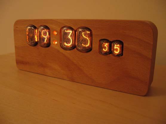
Nixie Clock Type Frank 3
|
|
|
- Colleen Pierce
- 5 years ago
- Views:
Transcription

1 Assembly Instructions And User Guide Nixie Clock Type Frank 3 Software version: 7R PCB Version: 11 April
2 1. INTRODUCTION 1.1 About the clock Nixie clock type Frank 3 is a compact design with all components and tubes mounted on a single PCB. The efficient use of board space is achieved by using a multiplex design to drive the display tubes. Only a single high-voltage binary-to-decimal decoder IC (74141) is required, and each tube is switched on in sequence very quickly to give the illusion that all the tubes are actually lit. The larger tubes for hours and minutes are type IN-12 with a digit height of 18mm. The smaller tubes for the seconds are type IN-17 with a digit height of 9mm. These tubes are Russian in origin and were produced during the 1980 s, when the technology was at it s most advanced. It is expected that the tubes will last for very many years and should not need replacing. The optional wooden case and hardware pack (rear cover, screws), supplied rough-machined, can be finished to give a very attractive clock for everyday living spaces. The quality of the final finish will reflect the time and care that is taken to finish the wood with successively finer grades of sandpaper. Alternatively, you may wish to design your own enclosure for the clock 1.2 Clock Features Nixie clock type Frank 3 has the following features: - Hours, Minutes and Seconds display - Uses the mains AC as the timebase - Selectable to work with 50Hz (Europe) or 60Hz (Americas) - Simple time setting using two buttons - 12 or 24 hour modes - Programmable leading zero blanking - Five programmable neon colon settings (Flashing AM/PM indication, illuminated AM/PM indication, both flashing, both on, both off) - Maintains time during setup mode, eg. When changing between Standard Time and Daylight Savings Time - Seconds can be reset to zero to make small adjustments / precisely set time - Infintely programmable night time blanking period to save tubes. - Separate modes for colon neons during night time blanking - Four display modes: Dim, Bright, Fading digits, Blanked - Ten different possible fade speeds in fading digit mode - 2 -
3 1.3 SAFETY DANGER: The clock pcb includes a switched-mode voltage booster circuit. This generates nominally 170 Volts DC, but is capable of generating up to 300 Volts before adjustment. Assembly may only be undertaken by individuals who are suitably qualified and experienced in electronics assembly, and are familiar with safe procedures for working with high voltages. If in doubt, refer to a suitably qualified engineer before proceeding. The voltages generated by this circuit can give a potentially LETHAL ELECTRIC SHOCK. DISCLAIMER: This product is supplied as a kit of parts, intended only for suitably qualified electronic engineers, who are suitably qualified and experienced in electronics assembly, and are familiar with safe procedures for working with high voltages. The supplier, his agents or associates accept no liability for any damage, injury or death arising from the use of this kit of parts. This is not a finished product, and the person assembling the kit is responsible for ensuring that the finished product complies with any applicable local regulations governing electrical equipment, eg. UL, CE, VDE
 - Wire cutters (TIP: A small pair of nail clippers works very")
4 2. TOOLS AND EQUIPMENT REQUIRED 2.1 Tools required to assemble the PCB The following tools will be required to assemble the PCB: - Soldering iron with a small tip (1-2 mm) - Wire cutters (TIP: A small pair of nail clippers works very well for this function) - Wire strippers (TIP: A small pair of scissors is quite suitable) - Multimeter - Small flat screwdriver for adjusting the high voltage supply 2.2 Materials you will need Solder lead / tin solder is preferred. Lead free solder, as now required to be used in commercial products in Europe, has a much higher melting point and can be very hard to work with. Desoldering wick (braid) can be useful if you accidentally create solder bridges between adjacent solder joints. 2.3 Other items you will need The clock kit does not include a power adapter. This is because the kit is sold to many countries around the world, each with very different household mains outlet socket types. It is more efficient for the user to buy a suitable adapter locally. This saves shipping a heavy adapter with the kit, and also the extra costs of managing stocks of many varied power adapters. The type of power adapter can be obtained at very low cost. The following type of adapter should be obtained and used with the kit: Mains AC to AC adapter (This is important, as the AC signal is needed for the timebase) Output 9-12V AC Minimum power output capability of 250 ma Output plug: 2.1mm pin A suitable adapter is shown in figure 1 below: Figure 1-4 -
5 3. LIST OF COMPONENTS 3.1 Table of components (In sequence) Circuit Designation Part Description Resistors R1 33K, ¼ Watt R2 1K, ¼ Watt R3 1K, ¼ Watt R4 390K, ¼ Watt R5 1K, ¼ Watt R6-R11 390K, ¼ Watt R12-R21 5.6K, ¼ Watt R22, R23 10K, ¼ Watt R24, R25 390K, ¼ Watt R26 33K, ¼ Watt R27 33K, ¼ Watt R28 33K, ¼ Watt R29 33K, ¼ Watt R30 Not installed R31 Not installed Capacitors C1 470uF, 16-25V, Electrolytic C2 100uF, 16-25V, Electrolytic C3 470uF, 16-25V, Electrolytic C4 22nF ceramic or polyester C5 1uF, 250V, Electrolytic C6 22nF, ceramic or polyester C7-C10 Not installed Transistors Q1 MPSA42 NPN Q2 IRF730 N-Channel MOSFET Q3-Q8 MPSA92 PNP Q9-Q16 MPSA42 NPN Diodes D1-D4 1N4001 D5 1N4936 fast recovery diode D6 5.6V Zener diode Integrated Circuits IC1 78L05 5V voltage regulator IC2 NE555 Timer IC IC3 PIC16F628A 8 bit Microcontroller IC / K155N Nixie driver IC5 Not installed Miscellaneous L1 100uH 470uH inductor NE1, NE2 4mm wire ended neon lamp NX1-NX4 IN-12 Nixie tube NX5, NX6 IN-17 Nixie tube SW1, SW2 Miniature push button VR1 1K Potentiometer PCB Frank 3 PCB IC Socket 18 Way IC Socket for IC3 CONN 2.1mm Power socket Cable ~60mm two way cable SKT1-44 1mm Harwin solder-in socket - 5 -
6 3.2 Parts list / Packing sheet Part Description Quantit y Resistors 33K, ¼ Watt 5 1K, ¼ Watt 3 390K, ¼ Watt 9 10K, ¼ Watt 2 5.6K, ¼ Watt 10 Capacitors 470uF, 16-25V, Electrolytic 2 100uF, 16-25V, Electrolytic 1 1uF, 250V, Electrolytic 1 22nF, ceramic or polyester 2 Transistors IRF730 N-Channel MOSFET 1 MPSA92 PNP 6 MPSA42 NPN 9 Diodes 1N N4936 fast recovery diode 1 5.6V Zener Diode 1 Integrated Circuits 78L05 5V voltage regulator 1 NE555 Timer IC 1 PIC16F628A 8 bit Microcontroller / K155N Nixie driver 1 Miscellaneous 100uH 470uH Inductor 1 4mm wire ended neon lamp 2 IN-12 Nixie tube 4 IN-17 Nixie tube 2 Miniature push button 2 1K Potentiometer 1 Frank 3a PCB 1 IC Socket, 18 way DIL 1 2.1mm Power Connector 1 2 Way cable 60mm piece 1 1mm Harwin solder-in socket 44 It is recommended that the kit is checked against the list above, to ensure all parts are present before commencing assembly
7 3.3 How to identify the correct components Resistors: The resistors are easy to identify by the coloured bands across the cylindrical body. Using a multimeter it should will be possible very quickly to identify the different values. Capacitors: Take care when identifying the 3 small ceramic or polyester capacitors. Depending on part availability, 2 or more different types may be supplied. The 22nF capacitors (C4, C6) may be marked 22nF, 22n, or 223. Transistors: The MOSFET Q2 can easily be identified as it has a large metal heatsink. Note: Due to part availability, this part may be substituted for a different but equivalent part number so the part marking may not necessarily be IRF730 Diodes: The four 1N4001 diodes D1-D4 are black and are marked 1N N4007 diodes may be supplied instead. They are identical for this circuit. The other black diode is D5, and again due to part availability it may be substituted for an equivalent. D6 is the small, glass bodied diode. Inductor L1 The inductor is a coil winding on a ferrite core and may or may not be finished with a heatshrink sleeve depending on part availability
8 4. ASSEMBLY OF THE PCB 4.1 1mm Sockets For Nixie Tubes There are 44 individual sockets that need to be soldered in. The best method is a follows. Place all sockets into the holes, noting that for each tube there is one hole that has no socket as marked on the PCB. When all sockets have been placed, place a flat and hard object over the top of the sockets, and turn the PCB over so you can solder from the underside. Be sure to insert the sockets FROM the front side of the PCB the side with the white component markings. Figure 2 below shows the solder side of the PCB after all the sockets have been inserted and soldered in. Figure Diodes D1-D4 Start by bending the leads of the four diodes to approximately match the spacing of the holes on the PCB. Insert the four diodes taking care to match up the white bands on the components with the component marking on the PCB. See Figure 3 below. Figure 3 Solder in the diodes, then using the wire clippers trim off the leads. 4.2 Diode D5 D5 is the remaining black diode. Again noting the position of the - 8 -


9 white band, place in position, solder in and trim the leads. Figure 4 showing D5 on the far left 4.3 IC2 NE555 Timer IC2 must be oriented correctly. The notch or dot at one end corresponds to pin 1. This goes into the SQUARE pad. Figure 5 shows IC2. Figure 5: IC2 correctly placed - 9 -

10 4.4 MOSFET Q2 and C4 The leads of the MOSFET need to be bent very carefully to allow the MOSFET to lie flat, as otherwise it would stand too high and foul any case that the clock will be put into. Follow the bending profile in figure 6, then place and solder Q2 into position as shown in figure 7. Also place C4 at this stage. Figure 6: Bending the leads of MOSFET Q2. Figure 7: MOSFET Q2 and C4-10 -


11 4.5 IC1 and Q1 IC1 and Q1 look very similar, so be careful to identify them correctly by the white marking on each component. The leads should not need to be formed, just separated a little. Align the flat of the body of these components with the marked flat on the PCB. Push each component into it s holes until the body is just 2 mm from the pcb. Solder in and trim the leads. Figure 8: IC1 and Q1 4.6 R1, R2, R3, R4, R5 These resistors, indeed all the resistors on the board need to be mounted upright to save space. The leads need to be formed as shown in figure 9. Bend the leads of each resistor as shown and solder in to the correct postion, making sure the component body is as close to the board as possible. Figure 9: Resistor leads formed for mounting upright
.")

12 Figure 10: Resistors R1-R5 mounted upright. 4.7 VR1 and L1 VR1 is used to tune the switched mode power supply to give the optimum voltage to drive the Nixie tubes (170V). Place L1 in position, and ensure it is as close to the board as possible. The leads of the component may not match exactly the spacing on the board this is perfectly normal. You can slightly form the leads so it is a nice firm and snug fit to the board. Solder and trim the leads as short as possible. Figure 11: VR1 and L1-12 -


 and white stripe (-VE)")

13 4.8 C1, C2, C3 and C5 Now it is time to solder in these four electrolytic capacitors. These components must be placed the correct way round or else the circuit will fail. Each capacitor has a positive lead, which has the longer lead, and a negative lead, marked by a white or grey stripe on the body. In Figure 12, the longer lead (+ve) and white stripe (-VE) can be clearly seen. Figure 12: Electrolytic capacitors Place each component as shown in figure 13 below, with the longer lead in the hole marked +. Solder in and trim the leads Figure 13: From left to right: C5, C3, C1, C2-13 -


14 4.9 Testing the switched mode (170V) and regulated (5V) power supplies. If you have reached this point and followed the correct order, then all the components for the 170V and 5V power supplies should now be on the board, and it is recommended that at this point the power supplies are tested before proceeding. To do so, you will need to make up the power input cable and socket, and of course have the 9-12V AC power adapter to hand. Also at this stage you will need a small flat blade screwdriver and a multimeter. DANGER: At this point, observe the safety warnings in section 1.3. When powered up, the board will generate up to 300V DC, and live parts are exposed. Observe high-voltage precautions Making up the power input cable Take the length (approx 60mm) of two way cable provided and strip the insulation for about 5 mm from all four ends. Note, the cable may be a different colour to that shown, and the insulation may be the same colour for both sides. As this cable carries AC, the conductors are not polarised. Referring to Figures 14-17, tin the ends of the cables, and solder to the 2.1mm connector as shown. Only 2 tags are used on the connector. Figure 14: Connector and 60mm piece of two way cable. Figure 15: Strip the insulation from the cable ends, and tin the copper conductors


15 Figure 16: Close-up showing which two tags need to be connected. Note: If you purchased the part-machined case, you will need to flatten the three solder terminals to stop them touching the circuit board when the cover is fixed. Figure 17: Connect the power input leads to the pads on the PCB Connect the other ends of the cable to the circuit board as shown in Figure 17. It is not necessary to feed the wire through the holes, you can just lay the tinned ends over the pads and solder in place
16 4.9.2 Testing the power supplies First, locate the three test points as shown in figure 18 below: Figure 18: Locate the three test points Then switch on the power supply. First, check that the 5V supply is in order. Use the GND, 5V and 170V test points to test first the 5V supply, then the 170V supply. Adjust the position of VR1 until the voltage is 170V. When all is in order, disconnect the power supply. Take care, as the output capacitor can still hold charge at 170V after the supply is disconnected. Before proceeding with the rest of the PCB assembly, it is a good idea to de-solder the power input cable, as it can get in the way when soldering the remaining components

17 4.10 Socket for IC3, and IC4. Insert the 18 Way IC socket into the PCB, ensuring that the notch at one end is aligned with the corresponding mark on the PCB. Insert IC4 directly into the PCB. Solder both components in place, but do NOT insert IC3 at this stage. This will be inserted at the very end of the assembly. Refer to figure 19. Figure 19: Socket for IC3, and IC R24-R29, C6, D6, Q15, Q16 The lead pitch of C6 may not match exactly the pitch of the holes on the PCB. If so, bend the leads sufficiently to insert the component. D6 needs to be placed the correct way round, so ensure the black band on the component body aligns with the band on the PCB marking Q3-Q8, Q9-Q14, R6-R23 This is perhaps the most time consuming stage of the assembly. There are six anode driver clusters. The function of each is to take the logic output from the 5V microcontroller, and switch on the 170V anode drive to the respective nixie tube. Pay particular attention to installing the correct transistor type (MPSA42 or MPSA92) in the correct location. The PCB should now look like Figure 20 Figure


18 4.13 Nixie tubes IN-17 To facilitate easy insertion of the flying leads into the small holes, it helps enormously to trim the flying leads at an angle with a pair of scissors as shown in figure 21. Figure 21: IN-17 flying leads trimmed to aid insertion into the PCB Feed all the wires in progressively. It is not as hard as it seems at first. Ensure the tubes are the correct way up. The part marking IN-17 should be to the RIGHT, but also check above to see if you can tell that the 5 and 3, which are visible, are the correct way up. After soldering in, trim flying leads SW1, SW2. Push buttons SW1 and SW2 are mounted on the REVERSE side of the PCB, so that the clock is adjusted from the back. You can choose to mount them on the front face if you wish, depending on your own particular clock case design
19 5. FINAL TESTING OF PCB All components except the 2 neon lamps should now have been installed. These can be installed later, when the unit is in it s final case to make sure they are set at the correct height. Make a final check that all components are well soldered in, and that there are no solder bridges unintentional solder links between adjacent pins. Insert IC3, matching up the notch on the resin body with the notch on the socket and the PCB markings. Insert the four IN-12 Nixie tubes into their sockets. It is quite easy to tell which way up they should be by looking into the glass at the numerals. Do not insert too hard, or you may break the glass seal at their base. Re-solder the power input cable, if you removed it for ease of assembly. The clock is now ready for use!! Don t forget to install the neon lamps, when you have finished your enclosure
20 - 20 -
21 6. HOW TO OPERATE THE CLOCK The two buttons have the following functions: SW1: Set SW2: Up / Reset Seconds Entering configuration mode: The principal settings of the clock are stored in flash memory your preferred configuration is stored even after powering off the clock. To access the configuration mode press and hold the Set button. After 2 seconds the minutes will start to flash. Continue holding the button a further 2 seconds until the clock displays in this format: In onfiguration mode the hours digits diplay the current parameter being adjusted, and the seconds digits display the current value stored against the parameter. For each parameter, and referring to the table below, scroll through the range of possible values by pressing the Up button. When the desired value has been reached, move on to the next parameter by pressing the Set button. When the last parameter has been set, pressing Set one more time will revert the clock back to time display mode. Parameter Description Values 1 AC timebase 0 60 Hz (default) 1 50 Hz 2 12 / 24 Hr mode 0 12 Hr (default) 1 24 Hr 3 Leading zero blanking 0 leading zero blanked (default) 1 leading zero displayed 4 Colon neons mode 0 AM/PM Indication, flashing (default) 1 AM/PM Indication, illuminated 2 Both flash 3 Both illuminated 4 Both off 5 Night blanking 0-23 (default 0) start hour 6 Night blanking 0-59 (default 0) start minutes 7 Night blanking 0-23 (default 0) stop hour 8 Night blanking stop minutes 0-59 (default 0) 9 Colon neons mode during night blanking 0 AM/PM Indication, flashing (default) 1 AM/PM Indication, illuminated 2 Both flash 3 Both illuminated 4 Both off 10 Reserved leave as 0 11 Reserved leave as 0 12 Fading Digits Speed 0 9 0:fast, 9:slow (0 default)
22 Setting the time: From time display mode, press and hold Set button for 2 seconds until the minutes digits start to flash. Press the Up / Reset Secs button to set the minutes. Briefly Press Set again and the hours will flash. Press the Up / Reset Secs button to set the hours. Briefly Press Set again to revert to normal clock operation. Resetting seconds: From time display mode, press and hold Up / Reset Secs button for 2 seconds. Seconds will be set to zero, and held until the button is released. Setting the display mode: From time display mode, briefly press Set button to toggle between the four display modes: Dim, standard change of digits Bright, standard change of digits Bright, Fading digits Blanked display, tubes are switched off Night Blanking: During programmed night blanking, the blanking may be overridden to see the time by briefly pressing the Set button. Tubes will remain lit until the next programmed blanking period

23 7. CIRCUIT DIAGRAM
24 8. DIMENSIONED DRAWING OF PCB
Nixie Clock Type Frank 2 Z570M
 Assembly Instructions And User Guide Nixie Clock Type Frank 2 Z570M Software version: 7R PCB Revision: 11 April 09-1 - 1. INTRODUCTION 1.1 About the clock Nixie clock type Frank 2 is a compact design with
Nixie Tube Clock Type Marsden
 Assembly Instructions And User Guide Nixie Tube Clock Type Marsden Software version: RTC-1.3 PCB Revision: 16 Aug 10-1 - 1. INTRODUCTION 1.1 About the clock Nixie clock type Marsden is a compact design
Nixie Clock Type Quattro'
 Assembly Instructions And User Guide Nixie Clock Type Quattro' - 1 - Issue Number Date REVISION HISTORY 2 8 Sept 2012 Errors corrected 1 27 July 2012 New document Reason for Issue - 2 - 1.1 Nixie Quattro
Assembly Instructions And User Guide. Nixie FunKlock. FunKlock Issue 4 (1 February 2017)
") Assembly Instructions And User Guide Nixie FunKlock - 1 - Issue Number Date REVISION HISTORY 4 1 February 2017 New diode for D2 3 27 December 2013 C7 / C8 error page 15 2 7 November 2013 Errors corrected
Assembly Instructions And User Guide Nixie FunKlock - 1 - Issue Number Date REVISION HISTORY 4 1 February 2017 New diode for D2 3 27 December 2013 C7 / C8 error page 15 2 7 November 2013 Errors corrected
SN-Class Nixie Clock Kits
 Assembly Instructions And User Guide SN-Class Nixie Clock Kits - 1 - REVISION HISTORY Issue Date Reason for Issue Number 1 20 November 2017 New document - 2 - 1. INTRODUCTION 1.1 About the How can the
Nixie Clock Type Frank 3'
 Assembly Instructions And User Guide Nixie Clock Type Frank 3' - 1 - REVISION HISTORY Issue Number Date Reason for Issue 4 16 December 2016 New diode for D2 3 12 November 2012 Improved first clock test
Nixie Clock Type SixNix
 Assembly Instructions And User Guide Nixie Clock Type SixNix - 1 - Issue Number Date REVISION HISTORY Reason for Issue 6 20 March 2014 Removed WWVB Support 5 14 July 2012 New Board Issue - 19 July 12 4
Nixie Clock Type IN-8 & NL840 Nixie'
 Assembly Instructions And User Guide Nixie Clock Type IN-8 & NL840 Nixie' - 1 - REVISION HISTORY Issue Number Date 4 15 December 2016 New diode for D2 3 30 August 2014 Typos 2 25 June 2014 Added NL840
Nixie Clock Type Nixie Maestro
 Assembly Instructions and User Guide Nixie Clock Type Nixie Maestro - 1 - Issue Number Date REVISION HISTORY Reason for Issue 4 01 April 2017 New version with neons for AM / PM 3 10 December 2014 Typing
Nixie Clock Type Nixie QTC
 Assembly Instructions And User Guide Nixie Clock Type Nixie QTC - 1 - REVISION HISTORY Issue Number Date Reason for Issue 12 10 September 2015 C6 changed to 33pF 11a 11 December 2014 C5 changed to 10pF.
Nixie Clock Type Nixie QTC Plus
 Assembly Instructions And User Guide Nixie Clock Type Nixie QTC Plus - 1 - REVISION HISTORY Issue Date Number Draft 1 29 August 2018 New document Reason for Issue - 2 - 1. INTRODUCTION 1.1 Nixie QTC Plus
Documentation VFD clock 8 a clock
 Documentation VFD clock 8 a clock This documentation is protected by our copyright. It must not be used for commercial purposes. Congratulations on your purchase of your VFD clock. To guarantee success
Assembly Instructions And User Guide. Elite Nixie. Nixie Tube Clock Elite Issue 2 (07 June 2018)
") Assembly Instructions And User Guide Elite Nixie - 1 - REVISION HISTORY Issue Number Date Reason for Issue 2 07 June 2018 Added more NL840 details 1 04 May 2018 New document - 2 - 1. INTRODUCTION Here
Assembly Instructions And User Guide Elite Nixie - 1 - REVISION HISTORY Issue Number Date Reason for Issue 2 07 June 2018 Added more NL840 details 1 04 May 2018 New document - 2 - 1. INTRODUCTION Here
Nixie Clock Kit V1.08 Assembly and Operation
 Nixie Clock Kit V1.08 Assembly and Operation Hardware Revision 14.05.2005 Software Version 6.0 Revision 19.04.2006 This document is copyrighted. No parts of this documentation may be used commercially.
Nixie Clock Kit IN-12B color LED backlit Operation Manual Nixie Clock Kit IN-12B V6.0 ( All Right Reserved 2015 )
") Nixie Clock Kit IN-B color LED backlit Operation Manual Nixie Clock Kit IN-B V. ( All Right Reserved ) - - Operation Manual IN-B Nixie Clock Power for your Nixie Clock The clock does not include a wall
Nixie Clock Kit IN-B color LED backlit Operation Manual Nixie Clock Kit IN-B V. ( All Right Reserved ) - - Operation Manual IN-B Nixie Clock Power for your Nixie Clock The clock does not include a wall
Introduction 1. Green status LED, controlled by output signal ST. Sounder, controlled by output signal Q6. Push switch on input D6
 Introduction 1 Welcome to the GENIE microcontroller system! The activity kit allows you to experiment with a wide variety of inputs and outputs... so why not try reading sensors, controlling lights or
Bill of Materials: Super Simple Water Level Control PART NO
 Super Simple Water Level Control PART NO. 2169109 Design a simple water controller in which electrodes are required to sense high and low water levels in a tank. Whenever the water level falls below the
7 SEGMENT LED DISPLAY KIT
 ESSENTIAL INFORMATION BUILD INSTRUCTIONS CHECKING YOUR PCB & FAULT-FINDING MECHANICAL DETAILS HOW THE KIT WORKS CREATE YOUR OWN SCORE BOARD WITH THIS 7 SEGMENT LED DISPLAY KIT Version 2.0 Which pages of
VU-1 VU Meter Kit Volume Unit Meter
 VU-1 VU Meter Kit Volume Unit Meter Simplicity Counts, Detail Matters. No part of this document may be reproduced, either mechanically or electronically, posted online on the Internet, in whole or in part,
Build A Video Switcher
 Build A Video Switcher VIDEOSISTEMAS serviciotecnico@videosistemas.com www.videosistemas.com Reprinted with permission from Electronics Now Magazine September 1997 issue Copyright Gernsback Publications,
Christmas LED Snowflake Project
 Christmas LED Snowflake Project Version 1.1 (01/12/2008) The snowflake is a follow-on from my Christmas star project from a few years ago. This year I decided to make a display using only white LEDs, shaped
MAKE AN RGB CONTROL KNOB.
 MAKE AN RGB CONTROL KNOB. This is a knob based colour changing controller that uses a custom programmed microcontroller to pack a lot of features into a small affordable kit. The module can drive up to
MONO AMPLIFIER KIT ESSENTIAL INFORMATION. Version 2.2 CREATE YOUR OWN SPEAKER DOCK WITH THIS
 ESSENTIAL INFORMATION BUILD INSTRUCTIONS CHECKING YOUR PCB & FAULT-FINDING MECHANICAL DETAILS HOW THE KIT WORKS CREATE YOUR OWN SPEAKER DOCK WITH THIS MONO AMPLIFIER KIT Version 2.2 Build Instructions
QUIZ BUZZER KIT TEACHING RESOURCES. Version 2.0 WHO ANSWERED FIRST? FIND OUT WITH THIS
 TEACHING RESOURCES SCHEMES OF WORK DEVELOPING A SPECIFICATION COMPONENT FACTSHEETS HOW TO SOLDER GUIDE WHO ANSWERED FIRST? FIND OUT WITH THIS QUIZ BUZZER KIT Version 2.0 Index of Sheets TEACHING RESOURCES
Introduction 1. Digital inputs D6 and D7. Battery connects here (red wire to +V, black wire to 0V )
") Introduction 1 Welcome to the magical world of GENIE! The project board is ideal when you want to add intelligence to other design or electronics projects. Simply wire up your inputs and outputs and away
Introduction 1 Welcome to the magical world of GENIE! The project board is ideal when you want to add intelligence to other design or electronics projects. Simply wire up your inputs and outputs and away
COLOUR CHANGING USB LAMP KIT
 TEACHING RESOURCES SCHEMES OF WORK DEVELOPING A SPECIFICATION COMPONENT FACTSHEETS HOW TO SOLDER GUIDE SEE AMAZING LIGHTING EFFECTS WITH THIS COLOUR CHANGING USB LAMP KIT Version 2.1 Index of Sheets TEACHING
DIY KIT MHZ 8-DIGIT FREQUENCY METER
 This kit is a stand-alone frequency meter capable of measuring repetitive signals up to a frequency of 50MHz. It has two frequency ranges (15 and 50 MHz) as well as two sampling rates (0.1 and 1 second).
ELECTRONIC GAME KIT TEACHING RESOURCES. Version 2.0 BUILD YOUR OWN MEMORY & REACTIONS
 TEACHING RESOURCES SCHEMES OF WORK DEVELOPING A SPECIFICATION COMPONENT FACTSHEETS HOW TO SOLDER GUIDE BUILD YOUR OWN MEMORY & REACTIONS ELECTRONIC GAME KIT Version 2.0 Index of Sheets TEACHING RESOURCES
Introduction 1. Green status LED, controlled by output signal ST
 Introduction 1 Welcome to the magical world of GENIE! The project board is ideal when you want to add intelligence to other design or electronics projects. Simply wire up your inputs and outputs and away
16 Stage Bi-Directional LED Sequencer
 16 Stage Bi-Directional LED Sequencer The bi-directional sequencer uses a 4 bit binary up/down counter (CD4516) and two "1 of 8 line decoders" (74HC138 or 74HCT138) to generate the popular "Night Rider"
Tube Cricket Build Guide
 Tube Cricket Build Guide The Tube Cricket is a small-wattage amp that puts out about 1 watt of audio power. With a 12AU7 tube-preamp and a JRC386 power amp, the Tube Cricket gives you great tone in a compact
Total solder points: 117 Difficulty level: beginner advanced. RGB Controller K8088 ILLUSTRATED ASSEMBLY MANUAL
 Total solder points: 117 Difficulty level: beginner 1 2 3 4 5 advanced RGB Controller K8088 Control incandescent bulbs, LEDs, common anode led strips, etc... ILLUSTRATED ASSEMBLY MANUAL H8088IP-1 Features
N3ZI Digital Dial Manual For kit with Backlit LCD Rev 4.00 Jan 2013 PCB
 N3ZI Digital Dial Manual For kit with Backlit LCD Rev 4.00 Jan 2013 PCB Kit Components Item Qty Designator Part Color/Marking PCB 1 LCD Display 1 LCD 1602 Volt Regulator 1 U1 78L05, Black TO-92 Prescaler
8 PIN PIC PROGRAMMABLE BOARD (DEVELOPMENT BOARD & PROJECT BOARD)
") ESSENTIAL INFORMATION BUILD INSTRUCTIONS CHECKING YOUR PCB & FAULT-FINDING MECHANICAL DETAILS HOW THE KIT WORKS LEARN ABOUT PROGRAMMING WITH THIS 8 PIN PIC PROGRAMMABLE BOARD (DEVELOPMENT BOARD & PROJECT
ESSENTIAL INFORMATION BUILD INSTRUCTIONS CHECKING YOUR PCB & FAULT-FINDING MECHANICAL DETAILS HOW THE KIT WORKS LEARN ABOUT PROGRAMMING WITH THIS 8 PIN PIC PROGRAMMABLE BOARD (DEVELOPMENT BOARD & PROJECT
Multi-Key v2.4 Multi-Function Amplifier Keying Interface
 Multi-Key v2.4 Multi-Function Amplifier Keying Interface ASSEMBLY & OPERATION INSTRUCTIONS INTRODUCTION The Harbach Electronics, LLC Multi-Key is a multi-function external device designed for the safe
NewScope-7A Operating Manual
 2016 SIMMCONN Labs, LLC All rights reserved NewScope-7A Operating Manual Preliminary May 13, 2017 NewScope-7A Operating Manual 1 Introduction... 3 1.1 Kit compatibility... 3 2 Initial Inspection... 3 3
DDS VFO CONSTRUCTION MANUAL. DDS VFO Construction Manual Issue 1.1 Page 1
 DDS VFO CONSTRUCTION MANUAL DDS VFO Construction Manual Issue 1.1 Page 1 Important Please read before starting assembly STATIC PRECAUTION The DDS VFO kit contains the following components which can be
N3ZI Digital Dial Manual For kit with Serial LCD Rev 3.04 Aug 2012
 N3ZI Digital Dial Manual For kit with Serial LCD Rev 3.04 Aug 2012 Kit properly assembled and configured for Standard Serial LCD (LCD Not yet connected) Kit Components Item Qty Designator Part Color/Marking
TECHNOLOGY WILL SAVE US: THE LUMIPHONE
 TECHNOLOGY WILL SAVE US: THE LUMIPHONE This is a step-by-step guide to soldering your own Lumiphone. The equipment you should have at your station: goggles, soldering mat, soldering Iron, solder and side
Fixed Audio Output for the K2 Don Wilhelm (W3FPR) & Tom Hammond (NØSS) v August 2009
 & Tom Hammond (NØSS) v August 2009") Fixed Audio Output for the K2 Don Wilhelm (W3FPR) & Tom Hammond (NØSS) v. 2.1 06 August 2009 I have had several requests to provide a fixed audio output from the K2. After looking at the circuits that
Fixed Audio Output for the K2 Don Wilhelm (W3FPR) & Tom Hammond (NØSS) v. 2.1 06 August 2009 I have had several requests to provide a fixed audio output from the K2. After looking at the circuits that
Color Organ Triple Deluxe II.
 http://wwwinstructablescom/id/color-organ-triple-deluxe-ii/ Food Living Outside Play Technology Workshop Color Organ Triple Deluxe II by ledartist on January 13, 2013 Table of Contents Color Organ Triple
LED Array Board.
 LED Array Board www.matrixtsl.com EB087 Contents About This Document 2 General Information 3 Board Layout 4 Testing This Product 5 Circuit Description 6 Circuit Diagram 7 About This Document This document
LED Backlight for Technics amplifiers
 LED Backlight for Technics amplifiers Technics SE-A900S Technics SE-A900SM2 Technics SE-A909S Technics SE-A1000 Technics SE-A1000M2 Technics SE-A1010 Rev. 1.2 B Description The LED module is designed to
Digital Clock. Perry Andrews. A Project By. Based on the PIC16F84A Micro controller. Revision C
 Digital Clock A Project By Perry Andrews Based on the PIC16F84A Micro controller. Revision C 23 rd January 2011 Contents Contents... 2 Introduction... 2 Design and Development... 3 Construction... 7 Conclusion...
ELECTRONIC GAME KIT ESSENTIAL INFORMATION. Version 2.0 BUILD YOUR OWN MEMORY & REACTIONS
 ESSENTIAL INFORMATION BUILD INSTRUCTIONS CHECKING YOUR PCB & FAULT-FINDING MECHANICAL DETAILS HOW THE KIT WORKS BUILD YOUR OWN MEMORY & REACTIONS ELECTRONIC GAME KIT Version 2.0 Build Instructions Before
DIY Guide - Building Franky v1.1, the SEGA Audio and Videocard for MSX
 DIY Guide - Building Franky v1.1, the SEGA Audio and Videocard for MSX 2015 FRS & MSXpró. Translation by FRS and Supersoniqs. Table of Contents Introduction... 3 Materials needed... 3 Audio volume boost...
Mal-2 assembly guide v1.0
 Mal-2 assembly guide v.0 SONIC POTIONS Schematic and BOM The BOM can be found on Google Docs Prepare the PCB Separate the PCBs using some pliers. PCB We start with the lower PCB and assemble it beginning
Industrial Monitor Update Kit
 Industrial Monitor Update Kit (Bulletin Number 6157) Installation Instructions 2 Table of Contents Table of Contents Industrial Monitor Update Kit... 3 Overview... 3 Part 1 - Initial Preparation... 5 Part
ADD AN AUDIO MESSAGE TO YOUR PRODUCT WITH THIS RECORD & PLAYBACK KIT
 ADD AN AUDIO MESSAGE TO YOUR PRODUCT WITH THIS RECORD & PLAYBACK KIT BUILD INSTRUCTIONS Before you start take a look at the Printed Circuit Board (PCB). The components go in the side with the writing on
RECORD & PLAYBACK KIT
 TEACHING RESOURCES SCHEMES OF WORK DEVELOPING A SPECIFICATION COMPONENT FACTSHEETS HOW TO SOLDER GUIDE ADD AN AUDIO MESSAGE TO YOUR PRODUCT WITH THIS RECORD & PLAYBACK KIT Version 2.1 Index of Sheets TEACHING
Bill of Materials: Magic Color PART NO
 Magic Color PART NO. 2193838 Magic color is a guessing game. With this game you can surprise your friends and leave them with amazement, how the game guesses what they have in their minds. Only two selections
EPROM pattern generator with "Genlock"
 EPROM pattern generator with "Genlock" This generator uses an EPROM to store several pictures that can then be selected by means of a thumb-wheel switch. Alternatively, if the pictures stored are in a
TKEY-K16. Touch CW automatic electronic keyer. (No moving parts no contacts) Assembly manual. Last review: March 15, 2018
 Assembly manual. Last review: March 15, 2018") TKEY-K16 Touch CW automatic electronic keyer (No moving parts no contacts) Assembly manual Last review: March 15, 2018 Commands and use manual of the K16 and Updates and news: www.ea3gcy.com Thanks for
TKEY-K16 Touch CW automatic electronic keyer (No moving parts no contacts) Assembly manual Last review: March 15, 2018 Commands and use manual of the K16 and Updates and news: www.ea3gcy.com Thanks for
"shell" digital storage oscilloscope (Beta)
") "shell" digital storage oscilloscope (Beta) 1. Main board: solder the element as the picture shows: 2. 1) Check the main board is normal or not Supply 9V power supply through the connector J7 (Note: The
"shell" digital storage oscilloscope (Beta) 1. Main board: solder the element as the picture shows: 2. 1) Check the main board is normal or not Supply 9V power supply through the connector J7 (Note: The
Cyclo Series. user manual. MartinArchitectural
 Cyclo Series user manual MartinArchitectural Measurements are in millimeters 63 Cyclo 02 88 Cyclo 03 1000 81 1190 88 Cyclo 04 98 88 2002 Martin Professional A/S, Denmark. All rights reserved. No part of
Modellbahn Digital Peter Stärz
 Modellbahn Digital Peter Stärz Dresdener Str. 68 D-02977 Hoyerswerda +49 3571 404027 www.firma-staerz.de info@firma-staerz.de 8-fold Track Occupancy Detector for digital systems with two-wire track (e.g.
Timer Modules. MEU11 24 Hour Module, MEU17 7 Day Module (Without Housing)
") Timer Modules MEU11 24 Hour Module, MEU17 7 Day Module (Without Housing) EMU11 24 Hour Module, EMU17 7 Day Module (With Housing Giving panel mounting facility) Installation & Operating Instructions 1 1.
Timer Modules MEU11 24 Hour Module, MEU17 7 Day Module (Without Housing) EMU11 24 Hour Module, EMU17 7 Day Module (With Housing Giving panel mounting facility) Installation & Operating Instructions 1 1.
Analog Style LED Clock
 Analog Style LED Clock Operation and Assembly Manual For use with PCB Rev 2.1 Copyright 2018 All Rights Reserved. Manual version 2.1c, for use with PCB revision 2.1, Software version 2.0.0. The electronic
Tip: Faller Mittelstadt Apartments with Controlled LED Lighting Date: , Addition
 Hi All, I have had the 130926 Mittelstadt apartments shown below on my layout for a long time and thought it was about time to add LED lighting to the buildings. With my success at upgrading the Faller
Total solder points: 123 Difficulty level: beginner 1. advanced AUDIO ANALYZER K8098. audio gea Give your. . high-tech ILLUSTRATED ASSEMBLY MANUAL
 Total solder points: 123 Difficulty level: beginner 1 2 3 4 5 advanced AUDIO ANALYZER K8098 ra audio gea Give your. look high-tech ILLUSTRATED ASSEMBLY MANUAL H8098IP-1 Features & Specifications Features
While the parts are already inventoried at the factory, please verify the inventory check as you go:
 Thank you for purchasing the kit for building the WJ9J DTMF controller. After building, you should read the document on operation (WJ9JDTMFControllerV5.pdf) in order to use. This is also in the link in
Lab 7: Soldering - Traffic Light Controller ReadMeFirst
 Lab 7: Soldering - Traffic Light Controller ReadMeFirst Lab Summary The two-way traffic light controller provides you with a quick project to learn basic soldering skills. Grading for the project has been
DEM 9ULNACK 3.4 GHz. PHEMT LNA amplifier complete kit assembly guide
 DEM 9ULNACK 3.4 GHz. PHEMT LNA amplifier complete kit assembly guide SPECIFICATIONS Noise Figure: < 0.8 db Gain: > 15 db Frequency Range: 3400-3500 MHz Input Voltage: 7-16 VDC Description: The 9ULNACK
Building a MidiBox LCD Cable
 Building a MidiBox LCD Cable By Jim Henry, 3-Apr-2004 An LCD panel may be connected to the Core module by a 16 conductor flat ribbon cable. A 16 pin insulation displacement connector (IDC) terminates one
POINTS POSITION INDICATOR PPI4
 POINTS POSITION INDICATOR PPI4 Monitors the brief positive operating voltage across points motors when they are switched Lights a corresponding led on a control panel to show the last operation of each
Parts Checklist - Please note there is no resistor R3. Diodes, LED and transistors are polarized see construction stages
 Xtal Check Kit build Read me first! -------- UPDATED GUIDE------ September 12, 2018--------- The following steps are designed to get your Xtal check kit built and operational. This is a good beginner s
STROBOSCOPE LIGHT EFFECT KIT
 STROBOSCOPE LIGHT EFFECT KIT Easy to build stroboscope for general applications Flash frequency: 5 to 15 flashes per second Power supply: 110VAC Power consumption: 13W max. PCB dimensions: 50 x 75mm modifications
This Unit may form part of a National Qualification Group Award or may be offered on a free standing basis.
 National Unit Specification: general information CODE F5JJ 11 SUMMARY The Unit is intended for candidates with little or no prior knowledge of Analogue or Digital Electronic Circuits. It provides an opportunity
Australian Technical Production Services
 Australian Technical Production Services Dual Rail Crowbar Copyright notice. These notes, the design, schematics and diagrams are Copyright Richard Freeman, 2015 While I am happy for the notes to be printed
VU Meter Buffer DIY Kit
 VU Meter Buffer DIY Kit Warning This document is distributed for educational purposes only. This equipment operates at potentially lethal voltages. Only trained, qualified personnel should operate, maintain,
RSL MusicPower Plug-In Installation Manual For Naim NAC 72 Preamp
 RSL MusicPower Plug-In Installation Manual For Naim NAC 72 Preamp (Updated to reflect the adjustable gain output boards Z200V) www.ryansoundlab.com RSL MusicPower Plug-In Installation Manual for Naim NAC
PRODUCT MANUAL. Product Description. Product Features. Manual will Review. LED Mini Neon 80W 24V DC. LED Mini Neon 80W 24V DC
 Product Description Thank you for purchasing Solid Apollo s! Solid Apollo s LED Mini Neon is a state of the art Neon LED lighting simulating the effect and look of neon in a thin continuous well-balanced
Build Your Own Clone Super 8 Kit Instructions
 Build Your Own Clone Super 8 Kit Instructions Warranty: BYOC, Inc. guarantees that your kit will be complete and that all parts and components will arrive as described, functioning and free of defect.
Product information. Front-door station series with video for surface-mount
 Product information Front-door station series with video for surface-mount series VPES series VPDS 2 05/2006 Table of contents Scope of delivery...3 Safety notices...3 General notes on the cabling in TCS
GUIDE TO ASSEMBLY OF ERICA SYNTHS DELAY MODULE
 If you are reading this, most probably, you are about to build Erica Synths DIY DELAY module. The module is 4mm deep, skiff friendly, has solid mechanical construction and doesn t require wiring. Erica
Instrukcja montażu. FLEX LED Neon Instalacja
 FLEX LED Neon Instalacja Instrukcja montażu Polned Sp. z o.o. ul. Falencka 7 PL05-090 Janki Tel. +48 22 4903434 +48 22 4903243 www.polned.pl info@polned.pl. Product Checking: 1) Unpack and carefully examine
Atari PICO Composite Mod Board Installation Instructions:
 Atari PICO Composite Mod Board Installation Instructions: Installation Guide 6 Switch Atari 2600 6 Switch Video Mod Installation Guide Disclaimer: I am not responsible for any damage done to your Atari.
FSM User Guide Page 1 of 28
 FSM User Guide Page 1 of 28 Field Strength Meter User Guide and Kit Assembly Instructions PCB V1.1 Important: Always use or print this document in colour as there are references to the colours of components.
MOD028 GLOCKENSPIEL TECHNO-MUSIC-OLOGY
 MOD028 GLOCKENSPIEL TECHNO-MUSIC-OLOGY MOD028 - Techno-music-ology Kit Contents Motor Controller PCBs 14 220R (red red brown gold) resistors 2 330R (orange orange brown gold) resistors 16 1N4001 diodes
STX Stairs lighting controller.
 Stairs lighting controller STX-1795 The STX-1795 controller serves for a dynamic control of the lighting of stairs. The lighting is switched on for consecutive steps, upwards or downwards, depending on
Lab 7: Soldering - Traffic Light Controller ReadMeFirst
 Lab 7: Soldering - Traffic Light Controller ReadMeFirst Lab Summary The two way traffic light controller provides you with a quick project to learn basic soldering skills. Grading for the project has been
SceneStyle2 User Guide
 SceneStyle2 User Guide Mode Lighting (UK) Limited. The Maltings, 63 High Street, Ware, Hertfordshire, SG12 9AD, UNITED KINGDOM. Telephone: +44 (0) 1920 462121 Facsimile: +44 (0) 1920 466881 e-mail: website:
DL-1A. RF dummy load - 50Ω 20W. Assembly manual. Last update: May 1, Thank you for constructing the DL-1A dummy load kit
 DL-1A RF dummy load - 50Ω 20W Assembly manual Last update: May 1, 2016 ea3gcy@gmail.com Updates and news at: www.qsl.net/ea3gcy Thank you for constructing the DL-1A dummy load kit Have fun assembling it
Light Emitting Diodes (LEDs)
") Light Emitting Diodes (LEDs) Example: Circuit symbol: Function LEDs emit light when an electric current passes through them. Connecting and soldering LEDs must be connected the correct way round, the diagram
Light Emitting Diodes (LEDs) Example: Circuit symbol: Function LEDs emit light when an electric current passes through them. Connecting and soldering LEDs must be connected the correct way round, the diagram
Thank you for purchasing this product. If installing for someone else, please ensure that the instructions are handed to the householder.
 Instruction Manual TPSE201 (181422) - BOSS TM Universal Programmer TPSE101 (569565) - BOSS TM Universal Timeswitch Thank you for purchasing this product. If installing for someone else, please ensure that
ASM-2 Manual Appendix A
 ASM-2 Manual Appendix A Assembly Guidelines June 30 th, 2005 Please note that this document is still currently under revision and we apologise for any errors or omissions. Readers should feel free to e-mail
Technical Information Bulletin
 June 4, 2001 #TIB0003 Units Affected: Model Serial Numbers Model Serial Numbers SVT-2PRO T2PDxxxxxxxxx SVTAV AXVDxxxxxxxxx ATLDxxxxxxxxx BJIDMAxxxxxxx SVT-2PROJ T2PJxxxxxxxxx SVTAVJ BAHJxxxxxxxxx ATLJxxxxxxxxx
Installation Manual SaVi Note Underwater LED Light
 Installation Manual SaVi Note Underwater LED Light Model Numbers SAVI-NOTE7, SAVI-NOTE0 Table of Contents Safety Precautions...2 SaVi Note Install Instructions...3- M Instructions...- Warnings READ AND
3B SCIENTIFIC PHYSICS
 B SCIENTIFIC PHYSICS Triode S 11 Instruction sheet 1/15 ALF 1 5 7 1 Guide pin Connection pins Cathode plate Heater filament 5 Grid Anode 7 -mm plug for connecting anode 1. Safety instructions Hot cathode
Reaction Game Kit MitchElectronics 2019
 Reaction Game Kit MitchElectronics 2019 www.mitchelectronics.co.uk CONTENTS Schematic 3 How It Works 4 Materials 6 Construction 8 Important Information 9 Page 2 SCHEMATIC Page 3 SCHEMATIC EXPLANATION The
Etherwave Plus Field Upgrade Instructions
 Etherwave Plus Field Upgrade Instructions The Etherwave Plus Field Upgrade is an advanced project for upgrading a standard Moog Music Etherwave theremin to the Etherwave Plus. The new features of the Etherwave
Build your own: Track Display
 Build your own: Track Display! " #! $% $ & ' $ ' ( ) * +, Track Display Manual 0706 web distribution version Table of Contents Section 1 Page 2 Quick Start Guide -Connecting 2 LEDs to Output #1 -Operating
Digital Economy Seven Programmer
 Digital Economy Seven Programmer Model: TRTD7N White Installation & Operating Instructions 1. General Information These instructions should be read carefully and retained for further reference and maintenance.
HORITA TR-100 USER MANUAL
 HORITA TR-100 USER MANUAL MULTI FRAME RATE SMPTE TIME CODE READER WITH LED DISPLAY Doc. 073129-00 Rev. B (C) Copyright 2014 P.O. Box 3993, Mission Viejo, CA 92690 (949) 489-0240 www.horita.com COPYRIGHT
INSTALLATION INSTRUCTIONS FOR
 INSTALLATION INSTRUCTIONS FOR MODEL 2240LED www.sportablescoreboards.com 1 Table of Contents 8 X 7 INDOOR SCOREBOARD... 3 THE SCOREBOARD SYSTEM SHOULD INCLUDE THE FOLLOWING PARTS:... 3 INSTRUCTIONS FOR
24 Channel Demultiplexer
 USER GUIDE 24 Channel Demultiplexer Doc. No. : 88 601 27 (408481 A?0/3) k!rand Lighting Issue: 2 Date : Oct 1990 i; Contents INTRODUCTION................................ 1 Delivery Inspection..............................
Arduino Modular IN-14 Nixie Clock Rev2 V45 All-In-One Modular Clock Operating Instructions & Construction Manual
 Arduino Modular IN-14 Nixie Clock Rev2 V45 All-In-One Modular Clock Operating Instructions & Construction Manual NixieClockModularInstructionManualRev2V45 Contact Information If you want to get in contact
The NorCal SMT Dummy Load Assembly and Operating Manual Rev. 1.0 January 4, 2005
 The NorCal SMT Dummy Load Assembly and Operating Manual Rev. 1.0 January 4, 2005 Copyright 2005 W3CD 1 1. Introduction The NorCal SMT Dummy Load is a practice kit for anyone wishing to gain some experience
MAIN PCB (The small one) OPEN MAIN BOARD BAG A
 OPEN MAIN BOARD BAG A") THANKS FOR CHOOSING ONE OF OUR KITS! This manual has been written taking into account the common issues that we often find people experience in our workshops. The order in which the components are placed
THANKS FOR CHOOSING ONE OF OUR KITS! This manual has been written taking into account the common issues that we often find people experience in our workshops. The order in which the components are placed
Dragonfly Quad. User Manual V1.4. Order code: EQLED101
 Dragonfly Quad User Manual V1.4 Order code: EQLED101 Safety advice WARNING FOR YOUR OWN SAFETY, PLEASE READ THIS USER MANUAL CAREFULLY BEFORE YOUR INITIAL START-UP! Before your initial start-up, please