Understanding VFD Allen Bradley Power Flex 4M Variable Frequency Drive. nfi
|
|
|
- Silas Farmer
- 5 years ago
- Views:
Transcription
1 Understanding VFD Allen Bradley Power Flex 4M Variable Frequency Drive nfi


2 Practical Demonstration of VFD Motor Speed Directly Proportional to Frequency Motor RPM= (120*F)/P Powerflex- 4M 0.4 KW= 0.5 Hp I/P: 230V 1/3 Phase O/P: Phase
3 Maximum Output Frequency Range 0 ~ 400 Hz
4 VFD Status Screen Command Freq. Volts reading Amperes Indicates freq. Control by VFD POT Motor RUN/Stop Indication Indicates Operation. Control by Keypad Direction RUN VFD Parameters STOP VFD Fault Keys to Read/Write Parameters Change Direction
 (0 ~ 50Hz) Analog Current Input (4 ~ 20mA) Analog")
5 Control Terminals Relay Feedback Terminals Freq. Feedback (0 ~ 10 V) (0 ~ 50Hz) Analog Current Input (4 ~ 20mA) Analog Voltage Input (0 ~ 10V)


6 Motor Output Terminals


7 3 Phase/ 1 Phase 220 VAC


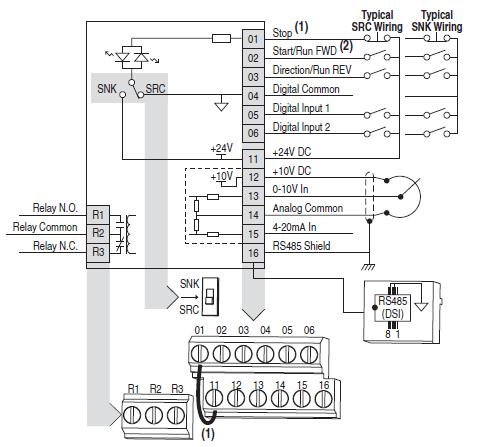
8 VFD Wiring Diagram Power Flex 4M Parameters to be used in this Course

9 How to? Reset the Drive & Enter Start-up Parameters nfi

10 AB Powerflex 4M Programming the VFD Step 1: Reset the Drive to Factory Setting Parameter: P112 Reset to Default Resets all parameter values to factory defaults.
11 AB Powerflex 4M Step 2: Enter Motor related Parameters P101 Motor NP Voltage Stop drive before changing this parameter. Set to the motor nameplate rated voltage. P102 Motor NP Hertz Stop drive before changing this parameter. Set to the motor nameplate rated frequency. P103 Motor OL Current Set to the maximum allowable motor current. P104 Minimum Frequency Sets the lowest frequency the drive will output continuously. Min/Max: 0.0/400.0 Hz P105 Maximum Frequency Sets the highest frequency the drive will output continuously. Min/Max: 0.0/400.0 Hz
12 Keypad Source of Operation nfi
13 AB Powerflex 4M Source of Operation P106 Start Source Stop drive before changing this parameter. Sets the control scheme used to start the drive.
14 3 Wire Source of Operation nfi
15 AB Powerflex 4M Source of Operation P106 Start Source Stop drive before changing this parameter. Sets the control scheme used to start the drive.
16 2 Wire Source of Operation nfi
17 AB Powerflex 4M Source of Operation P106 Start Source Stop drive before changing this parameter. Sets the control scheme used to start the drive.
18 AB Powerflex 4M Stop Method P107 Stop Mode Active stop mode for all stop sources 0 Ramp, CF (1) (Default) P110 Dec. Time Ramp to Stop. Stop command clears active fault. 1 Coast, CF (1) Coast to Stop. Stop command clears active fault.
19 Drive Pot Source of Speed nfi
20 AB Powerflex 4M Parameter Organization - Program P108 Speed Reference Sets the source of the speed reference to the drive.

21 Internal Freq. Source of Speed nfi
22 AB Powerflex 4M Parameter Organization - Program P108 Speed Reference Sets the source of the speed reference to the drive.

23 0 ~ 10 VIN Source of Speed nfi

24 AB Powerflex 4M Parameter Organization - Program P108 Speed Reference Sets the source of the speed reference to the drive.
25 Preset Freq. Source of Speed nfi
26 AB Powerflex 4M Parameter Organization - Program P108 Speed Reference Sets the source of the speed reference to the drive. DIN 2 DIN 1 Speed Parameter Speed (in Hz) 0 0 A Hz 0 1 A411 5 Hz 1 0 A Hz 1 1 A413 20Hz
27 Acc./Dec. Time nfi
28 Acc./ Dec. P109 Acc. Time Sets the rate of deceleration for all speed decreases. AB Powerflex 4M P110 Dec. Time Sets the rate of deceleration for all speed decreases.
29 Acc./Dec. Time 2 nfi
30 AB Powerflex 4M Acc./ Dec. 2 Step 1- Enter the Time Default Acc./Dec. Time Acc./Dec. Time 2 P109 Acc. Time Sets the rate of acceleration (0 ~ 600secs). A401 Acc. Time 2 Sets the rate of acceleration (0 ~ 600secs). P110 Dec. Time Sets the rate of deceleration (0.1 ~ 600secs). A402 Dec. Time Sets the rate of deceleration. (0.1 ~ 600secs) Step 2- Assign the Function T201/T202 DIN Function Enter 1 for Acc./Dec. Time 2 Step 3- Energize DIN 1/DIN 2
31 JOG Mode nfi
32 AB Powerflex 4M Jog/Inch Frequency To adjust the Speed of Motor at Jog Mode Jog Acc./ Dec Time Step 2- Assign the Function T201/T202 DIN Function Enter 2 for Jog Mode Step 3- Energize DIN 1/DIN to sec or 0.01 to sec Step 1- Enter the Jog Freq., Acc./Dec. Time A404- Jog Freq. A405- Jog Acc./Dec. Time
33 Local Control nfi
34 AB Powerflex 4M Local Control When active, sets integral keypad as start source and potentiometer on the integral keypad as speed source Step 1- Assign the Function T201/T202 DIN Function Enter 5 for Local Operation Step 2- Energize DIN 1/DIN 2 Speed Source Operation Source

35 Aux Fault nfi
36 AB Powerflex 4M Aux Fault- NC When enabled, an F2 Auxiliary Input fault will occur when the input is removed. Step 1- Assign the Function Step 2- Energize DIN 1 To include fault T201 DIN Function Enter 3 for Aux Fault Clear Fault- NO When active, clears an active fault. Step 1- Assign the Function Step 2- Energize DIN 2 T202 DIN Function To clear the fault Enter 7 for Clear Fault
37 Override 0 ~ 10 VIN Source of Speed nfi
38 AB Powerflex 4M Override 0 ~ 10VIN Selects 0-10V or ±10V control as the frequency reference. Start source is not changed. Step 1- Assign the Function Step 2- Energize DIN 1/DIN 2 To override 0 ~ 10V Source T201/T202 DIN Function Enter 13 for 0 ~ 10VIN

39 VFD Scaling Adjusting Voltage by Frequency Curves
40 VFD Scaling P105 Max. Freq. (0 ~ 400Hz) 50 Hz 1 Volt =5Hz 25 Hz P104 Min. Freq. 0 Hz (0 ~ 400 Hz) T211 = 0% (default) Range 0 ~ 100% 0V 5V 10V t211 Min. Volts t212 Max. Volts T212 = 100% (default) Range 0 ~ 100%
41 VFD Scaling P105 Max. Freq. (0 ~ 400Hz) 50 Hz 20 Hz P104 Min. Freq. (10 Hz) 10 Hz T211 = 0% (default) Range 0 ~ 100% 0V 5V 10V t211 Min. Volts t212 Max. Volts T212 = 100% (default) Range 0 ~ 100%
42 VFD Scaling Scaling Value = Bias Voltage/Full Voltage x 100 = 1/10 x 100 = 10% P105 Max. Freq. (0 ~ 400Hz) 50 Hz 25 Hz P104 Min. Freq. (0 ~ 400 Hz) 0 Hz 1V 4.5V 10V t211 Min. Volts T211 = 10% Range 0 ~ 100% t212 Max. Volts T212 = 100% (default) Range 0 ~ 100%
43 VFD Scaling Scaling Value = Bias Voltage/Full Voltage x 100 = 5/10 x 100 = 50% P105 Max. Freq. (0 ~ 400Hz) 50 Hz 25 Hz P104 Min. Freq. (0 ~ 400 Hz) 0 Hz 5V t211 Min. Volts T211 = 50% Range 0 ~ 100% 7.5V 10V t212 Max. Volts T212 = 100% (default) Range 0 ~ 100%
44 VFD Scaling P105 Max. Freq. (0 ~ 400Hz) 50 Hz P104 Min. Freq. (0 ~ 400 Hz) 25 Hz 0 Hz 0V t211 Min. Volts 2.5V T211 = 0% Range 0 ~ 100% 5V t212 Max. Volts Scaling Value = (Full voltage - Bias Voltage)/Full Voltage x 100 = (10-5/10 x 100 = 50% T212 = 50% Range 0 ~ 100%
45 VFD Scaling P105 Max. Freq. (0 ~ 400Hz) 50 Hz Scaling Value = Bias Voltage/Full Voltage x 100 = 2.5/10 x 100 = 25% 25 Hz Scaling Value = (Full voltage - Bias Voltage)/Full Voltage x 100 = (10-2.5/10 x 100 = 75% P104 Min. Freq. (0 ~ 400 Hz) 0 Hz t211 Min. Volts T211 = 25% Range 0 ~ 100% 2.5V 5V 7.5V t212 Max. Volts T212 = 75% Range 0 ~ 100%
46 VFD Scaling P105 Max. Freq. (0 ~ 400Hz) 50 Hz Scaling Value = Bias Voltage/Full Voltage x 100 = 5/10 x 100 = 50% P104 Min. Freq. (0 ~ 400 Hz) 25 Hz Scaling Value = (Full voltage - Bias Voltage)/Full Voltage x 100 = (10-2.5/10 x 100 = 75% 0 Hz t211 Min. Volts T211 = 50% Range 0 ~ 100% 5V 7.5V t212 Max. Volts T212 = 75% Range 0 ~ 100%
47 Feedback Signals nfi

48 Feedback Relay Type Related Parameter: t221 & t222 Sets the condition that changes the state of the output relay contacts. Sets the trip point for the digital output relay if the value of t221 [Relay Out Sel] is 6, 7, 8, 10 or VFD Operation Run & Stop t221 =2 2. VFD Running Reverse t221 = 3 3. VFD Desired Frequency Attained t221= 6 t222 = Frequency


49 PLC & VFD Advanced Course 4 PLC s Training Platforms $149 Course Highlights: Course Link: 30 Live Practical Classes on PLC, Analog Cards & AC drives- VFD 100+ PLC Video Tutorials with Lifetime Access & FREE PLC Simulator FREE Circuits Diagram For more courses visit

50 Thank You nfi
Understanding VFD. Variable Frequency Drive. nfi. nfi
 Understanding VFD Variable Frequency Drive Practical Demonstration of VFD Delta- M Series 1.5 KW I/P: 230V 1/3 Phase O/P: 230 3 Phase VFD Status Screen Motor OFF Command Freq. Parameters Direction Amperes
For applications from 0.25 to 5 HP, the MD60 is a simple AC Microdrive that can be panel mounted as well as wall or machine mounted.
 For applications from 0.25 to 5 HP, the MD60 is a simple AC Microdrive that can be panel mounted as well as wall or machine mounted. N223 Reliance Electric s MD60 AC Drive is ready to operate out-of-the-box!
RYKO Italia s.r.l. V. Casale Morano Po (Al) t f
 t f") Italia RYKO Italia s.r.l. V. Casale 43-15025 Morano Po (Al) t.0142 494411 f. 85872 June 30, 2003 ITALIA SERVICE BULLETIN - # 4-013 VFD parameter settings for conveyor equipment with Mitsubishi PLC MACHINES
Italia RYKO Italia s.r.l. V. Casale 43-15025 Morano Po (Al) t.0142 494411 f. 85872 June 30, 2003 ITALIA SERVICE BULLETIN - # 4-013 VFD parameter settings for conveyor equipment with Mitsubishi PLC MACHINES
AF-300 E11 Adjustable Frequency Drive
 AF-300 E11 Adjustable Frequency Drive The AF-300 E11 adjustable frequency drive is GE s new generation of micro drives. GE recognized your need for a high-performance, full-featured compact drive and designed
BOSTON GEAR CONTROLLERS. ACE 10 Series 1/4 through 3 HP Adjustable Frequency AC Motor Controllers MEX (55) QRO (442)
 QRO (442)") BOSTON GEAR CONTROLLERS ACE 10 Series 1/4 through 3 HP Adjustable Frequency AC Motor Controllers ACE 10 Series Noted for exceptionally low motor noise, high starting torque and cool operation in a compact
BOSTON GEAR CONTROLLERS ACE 10 Series 1/4 through 3 HP Adjustable Frequency AC Motor Controllers ACE 10 Series Noted for exceptionally low motor noise, high starting torque and cool operation in a compact
VAT 20 Adjustable Frequency Drive
 VAT 0 Adjustable Frequency Drive VAT 0 Adjustable Frequency Drive The VAT 0 is a small, flexible, low cost, well performing AC drive designed for use in small machines such as fans and conveyors. The drive
2. Using LCD Digital Operator
 2. Using LCD Digital Operator Functions of LCD digital operator JNEP-31(V) LCD digital operator has 2 modes: mode and mode. When the inverter is stopped, mode or mode can be selected by pressing the. In
RM5 User Manual Warnings.
 A RM5 User Manual Warnings. Danger Hazardous High Voltage Ground the control before servicing Remove all power and wait 10 minutes Verify that no voltage is present Failure to comply will result in death
DAAB DB409 INSTRUCTION MANUAL FOR THE VFD-EL FREQUENCY CONVERTER. For the DAAB EP104 automatic control system with software version 4.
 DAAB DB409 INSTRUCTION MANUAL FOR THE VFD-EL FREQUENCY CONVERTER For the DAAB EP104 automatic control system with software version 4.07 Revision: 12 FAAC Nordic AB BOX 125, SE-284 22 PERSTORP SWEDEN, +46
ADJUSTABLE SPEED DRIVES. nc1 Drive
 ADJUSTABLE SPEED DRIVES nc1 Drive Ultra-Compact Sub-Micro Drive The nc1 is a sub-micro, or nano-sized drive with a full range of features to meet the needs of nearly any user. The nc1 is designed to be
General Description. Specifications. 2.1 Electrical
 Instruction Manual Models EPN020-000 EPR020-000 EPN040-000 EPR040-000 EPN060-000 EPR060-000 EPN075-000 EPR075-000 EPN100-000 EPR100-000 EPN125-000 EPR125-000 EPN150-000 EPR150-000 EPN200-000 EPR200-000
Electronic Lineshaft With Alignment F7 Drive Software Technical Manual
 Electronic Lineshaft With Alignment F7 Drive Software Technical Manual Software Number: VSF11005X, Drive Models: CIMR-F7UXXXXXX-064, CIMR-F7UXXXXXX-065 Document Number: TM.F7SW.064, Date: 02/25/2010, Rev:
Self Excited Automatic Voltage Regulator For Generator Compatible with Marathon SE350* Operation Manual
 Self Excited Automatic Voltage Regulator For Generator Compatible with Marathon SE350* Operation Manual s * Use for reference purpose only and not a genuine Marathon product. 1. INTRODUCTION Sensing Input
Definite Purpose Contactors
 Definite Purpose Contactors Your order must include: 1) complete cat. no. of selected contactor, and 2) auxiliary contacts, if required. 20/25 FLA 1 and 2 Pole 1-Pole Contactor with Shunt 2-Pole Contactor
FS340 and FS641. High Performance Low Cost Controller for Flying Shears and Saws
 control motion interface motrona GmbH Zwischen den Wegen 32 78239 Rielasingen - Germany Tel. +49 (0)7731-9332-0 Fax +49 (0)7731-9332-30 info@motrona.com www.motrona.com FS340 and FS641 High Performance
HS-509 VIBRATION TRIP MODULE
 HS-509 VIBRATION TRIP MODULE 1. Overview The HS-509 is a configurable trip amplifier capable of accepting a 4-20mA signal from a HS-420 sensor and providing two trip action relay outputs along with an
M Traverse User Manual Revision F
 M Traverse User Manual 0001-0122 Revision F i Technical Assistance If you have comments or questions concerning the operation of the M Traverse, a member of our Technical Support Staff will be happy to
AS09..S 3-pole Contactors - Spring Terminals
 4 kw 5 hp AS09..S 3-pole Contactors - Spring AC Operated Description - 3-pole contactors with spring terminals, - N.C. or N.O. built-in auxiliary contact, - Rail-mounted, no tools required, - Additional
Your First Choice for Control Systems Solutions
 ONTROL SYSTEMS SOLUTIONS FOR PREISION MOTION TEHNOLOGY 135 YEARS OF POSITIONING & PROESS SOLUTIONS Since 1883, Duff-Norton has been at the forefront of precision motion technology. Providing a continued
1.1. IEC Contactors and Starters. Contents Description Relays and Timers... Miniature Controls... Contactors and Starters. XT IEC Power Control
 IEC Contactors and Starters. XT Family of Contactors Contactors and Starters Product Description The Eaton XT contactors and starters includes nonreversing and reversing contactors, overload relays and
Series CT7N Bimetallic Overload Relays
 Series CT7N imetallic Overload Relays Choose CT7N overloads in DC applications and when monitoring Variable Frequency Drives Sprecher + Schuh has always paid particular attention to the subject of motor
Digital Ratio Controller
 Digital Ratio Controller RSC-406 Control Panel USER S MANUAL RATIO CONTROLLER SPEED RUN PRG ERR RATIO % CH RSC-406 Prelude Thank you for applying our RSC-406 Ratio Controller (abb.406) to you machinery
EA350. Generator Automatic Voltage Regulator Operation Manual
 Generator Automatic Voltage Regulator Operation Manual Self Excited Automatic Voltage Regulator For General Generators Compatible with Marathon SE350* * Use for reference purpose only and not a genuine
VLC-3 USER'S MANUAL. Light Program Controller. M rev. 04 K rev. 00 & ( ( 5, 352*5$0 1 : $ 2 ' 6(77,1*6 )81&7,216
81&7,216") Light Program Controller VLC-3 USER'S MANUAL +50,1 +50,1 1 : $ ' 2 7. 6 8 ' 5, 7 6 6. $ ( 3 352*5$0 0,16(& )81&7,216 6(77,1*6 & 8 5 5 ( 1 7 3 ( 5, 2 ' M 890-00189 rev. 04 K 895-00406 rev. 00 GENERAL...
Light Program Controller VLC-3 USER'S MANUAL +50,1 +50,1 1 : $ ' 2 7. 6 8 ' 5, 7 6 6. $ ( 3 352*5$0 0,16(& )81&7,216 6(77,1*6 & 8 5 5 ( 1 7 3 ( 5, 2 ' M 890-00189 rev. 04 K 895-00406 rev. 00 GENERAL...
DATA SHEET. Synchronisers, FAS-113DG ANSI code 25
 DATA SHEET Synchronisers, ANSI code 25 Synchronisation of generator to busbar Circuit breaker time compensation LED indication of status LED for activated control LED for synchronising signal 35 mm DIN
Inverters Selection Guide
 Inverters Selection Guide Table of contents SYSDRIVE inverters Page Inverter - Outline...................................................................... 1 3G3EV................................................................................
ELCOM. Part Application Instruction. Release (V S 0.5) YS Kim S Jeong. OS Program Change to V S1.5 YS Kim S Jeong
 YS Kim S Jeong. OS Program Change to V S1.5 YS Kim S Jeong") Page 1/23 Door System(S-type) Rev. No. 0 1 2 3 Revision History Date Aug. 2004 Jun 2006 Sep 2006 Oct 2008 Revision Contents Prepared by Checked by Release (V S 0.5) YS Kim S Jeong OS Program Change to
Page 1/23 Door System(S-type) Rev. No. 0 1 2 3 Revision History Date Aug. 2004 Jun 2006 Sep 2006 Oct 2008 Revision Contents Prepared by Checked by Release (V S 0.5) YS Kim S Jeong OS Program Change to
Low-Cost, Single-CT, Automatic Power Factor Controller for Balanced Three-Phase Reactive Power Compensation User Manual
 Low-Cost, Single-CT, Automatic Power Factor Controller for Balanced Three-Phase Reactive Power Compensation User Manual Firmware Version: 1.0.1.8 Page 1 of 24 Dated: 23 rd June 2016 CAUTIONS: NOTE These
Figure 1: Standard 906 Sensor and Pulser Disc. Figure 2: Standard 906 Sensor and Pulser Wrap
 Description: The TR5000 is a Full Logic Control Process ratemeter that can display up to three separate values of rate and compare them to programmable set points. Rates A & B can be programmed by the
High performance circuit breakers
 Series High performance Description The high performance MCB offers a compact solution to circuit protection. The devices are DIN rail mounted. The is available with application-specific trip characteristics
Inverters Selection Guide
 Inverters Selection Guide Table of contents SYSDRIVE inverters Page Inverter - Outline...................................................................... 1 3G3EV................................................................................
MILLITARY SPECIFICATION SHEET
 INCH-POUND MILLITARY SPECIFICATION SHEET 10 November 2000 SUPERSEDING MIL-R-6106/14B 10 March 1989 RELAY, ELECTRIC, PERMANENT DRIVE, 50 AMP, SPDT (DB) DOUBLE MAKE DOUBLE BREAK AUXILIARY CONTACTS (5 AMP),
EVC300i. Generator Automatic Voltage Regulator Operation Manual
 EVC300i Generator Automatic Voltage Regulator Operation Manual 1. INTRODUCTION The EVC300i Voltage Regulator is thyristor base to control the DC exciter field power of conventional 50 or 60 Hz brushless
Assembly. Front view. LEDs. Parametrization interface. Power Bus
 otation Speed Monitor Features Assembly 1-channel signal conditioner 2 V DC supply Input for 2- or -wire sensors Input frequency 10 mhz... 50 khz elay contact output Start-up override and restart inhibit
EVC600i. Generator Automatic Voltage Regulator Operation Manual
 EVC600i Generator Automatic Voltage Regulator Operation Manual 1. INTRODUCTION The EVC600i Voltage Regulator is thyristor base to control the DC exciter field power of conventional 50 or 60 Hz brushless
EA63-7D. Generator Automatic Voltage Regulator Operation Manual. Self Excited Automatic Voltage Regulator
 EA63-7D Generator Automatic Voltage Regulator Operation Manual Self Excited Automatic Voltage Regulator SP POWERWORLD LTD Willows, Waterside, Ryhall, Stamford, Lincs, PE9 4EY, UK Tel: +44 1780 756872 -
PBC series. RoHS. Ready. IEC-Type Contactors & Accessories 9-80 Amp AC-3, Amp AC-1 AC Coils. P&B PBC Series IEC Type Contactors & Accessories
 PBC series IEC-Type Contactors & Accessories 9-80 Amp AC-3, 25-125 Amp AC-1 AC Coils File E38802 (PBC) RoHS Ready Users should thoroughly review the technical data before selecting a product part number.
SPECIFICATION NO Model 207 Automatic GTAW Welding System
 1.0 Introduction The Model 207 is a completely self-contained Gas Tungsten Arc Welding (GTAW) System requiring only input power, inert gas and AMI Welding Head (or manual torch) for operation. Its small
Installation and User Guide 458/CTR8 8-Channel Ballast Controller Module
 Installation and User Guide 458/CTR8 8-Channel Ballast Controller Module Helvar Data is subject to change without notice. www.helvar.com i Contents Section Page Introduction 1 Installation 2 1. Attach
02/11/2015
 DIN Rail Mount 17.5 mm MUS/MUSF 80 AC/DC Part number 84872141 Control relays monitoring their own power supply - MUS : Over/undervoltage control Selectable latching (memory) function - MUSF : Over/undervoltage
Bulletin 190 IEC Modular Starter System
 Bulletin 90 Table of Contents Selection Guide Description Page Bulletin 90....................................... Accessories....................................... 7 Specifications.....................................
Panel cutout required: 1.772" x 3.622" (45mm x 92mm) 1.76" (45mm) 2.45" (62mm) 3.20" (81mm) 3.60" (91mm) 0.59" (15mm) Special Features
 1.76 (45mm) 2.45 (62mm) 3.20 (81mm) 3.60 (91mm) 0.59 (15mm) Special Features") NEMA4X, IP65 Front Bezel Meter with Relays Option RELAY2 RELAY1 24V OUT POWER 4 3 2 1 6 5 2 1 2 1 NO NC COM NO NC COM RTD TC P P RTD 3 4 1 2 5 TC 6 SWITCH Rear View Gasket APM765 Panel Meter Description
NEMA4X, IP65 Front Bezel Meter with Relays Option RELAY2 RELAY1 24V OUT POWER 4 3 2 1 6 5 2 1 2 1 NO NC COM NO NC COM RTD TC P P RTD 3 4 1 2 5 TC 6 SWITCH Rear View Gasket APM765 Panel Meter Description
Operating Instructions for Throttle Valves Using VRC Valve Positioner
 ThrottleMaster TM Operating Instructions for Throttle Valves Using VRC Valve Positioner p/n: X709116 $10.00 3/2012 Throttlemaster is a registered trademark of Vacuum Research Corporation Introduction The
Single Axis Position Controller
 SERIES P8721-000-P Single Axis Position Controller Closed loop Analogue with +/- 10v control and 2 or 3 switched speed operation 200 Line programme Manual Operation Single Operation Auxiliary functions
110 Volt AC at 50 Hertz, 120 Volt AC at 60 Hertz. 20 Amp (UL Continuous), 7 Amp (AC-3), 22 Amp (AC-1)
, 7 Amp (AC-3), 22 Amp (AC-1)") 80 South Street 7596-726, TX Nacogdoches Phone: 96-569-79 Fax: 96-560-685 XTCE007B0A PH FVNR 7A IEC Contactor Eaton Corp Catalog Number XTCE007B0A Manufacturer Eaton Corp Description Magnetic Contactor,
80 South Street 7596-726, TX Nacogdoches Phone: 96-569-79 Fax: 96-560-685 XTCE007B0A PH FVNR 7A IEC Contactor Eaton Corp Catalog Number XTCE007B0A Manufacturer Eaton Corp Description Magnetic Contactor,
Vorne Industries. 87/719 Analog Input Module User's Manual Industrial Drive Itasca, IL (630) Telefax (630)
 Telefax (630)") Vorne Industries 87/719 Analog Input Module User's Manual 1445 Industrial Drive Itasca, IL 60143-1849 (630) 875-3600 Telefax (630) 875-3609 . 3 Chapter 1 Introduction... 1.1 Accessing Wiring Connections
Vorne Industries 87/719 Analog Input Module User's Manual 1445 Industrial Drive Itasca, IL 60143-1849 (630) 875-3600 Telefax (630) 875-3609 . 3 Chapter 1 Introduction... 1.1 Accessing Wiring Connections
GENMARK Engineering & Management # Street Edmonton, AB T5S 1R5 CANADA Phone (780) Fax (780)
 Fax (780)") GENMARK Engineering & Management #200 10459-178 Street Edmonton, AB T5S 1R5 CANADA Phone (780) 461-9234 Fax (780) 461-9624 GENMARK Engineering & Management Contract engineering and management services
GENMARK Engineering & Management #200 10459-178 Street Edmonton, AB T5S 1R5 CANADA Phone (780) 461-9234 Fax (780) 461-9624 GENMARK Engineering & Management Contract engineering and management services
BE1-81O/U Frequency Protection. Washington State University Hands-On Relay School.
 Frequency Protection Washington State University Hands-On Relay School www.basler.com Relay Benefits As many as four independent, adjustable frequency setpoints and time delays Each setpoint has output
1.1. IEC Contactors and Starters. Contents Description Relays and Timers... Miniature Controls... Contactors and Starters. XT IEC Power Control
 . XT Family of Contactors Contactors and Starters Product Description The Eaton XT contactors and starters includes nonreversing and reversing contactors, overload relays and a variety of related accessories.
llen-bradley 194R-HM4-NFPA3
 Technical Data Rotary Disconnect Switch Specifications Bulletin Number 194R Topic Page Product Line Overview 2 General Specifications Fuse Description 12 Approximate Dimensions 14 Additional Resources
ORDERING Page 6 BASLER RELAY STANDARDS, DIMENSIONS, ACCESSORIES Request bulletin SDA
 BE1-59NC CAPACITOR NEUTRAL OVERVOLTAGE RELAY The BE1-59NC Capacitor Neutral Overvoltage Relay provides sensitive protection for capacitor banks. ADDITIONAL INFORMATION INSTRUCTION MANUAL ADVANTAGES Helps
Single Axis Position Controller
 SERIES P9511 Single Axis Position Controller Compact Construction Simple Go-to operation Integrated Relay Output Integrated Mains Power Supply ELEKTRO-TRADING sp. Z o.o. 44-109 Gliwice, ul. Mechaników
Bulletin 109 TABLE OF CONTENTS Bulletin 109 IEC Non-Reversing Starters. Enclosed Type Molded Plastic. Description Page Description Page
 3a Enclosed Type Molded Plastic Compact Design Impact-Resistant Molded Enclosures IP42 (Type 1) or IP66 (Type4/4X/12)Enclosure Ratings Solid-State Overload Relays Meets International Standards 109-C09KDA1E-1-4R1-7
1.1. IEC Contactors and Starters. Contents Description Relays and Timers... Miniature Controls... Contactors and Starters. XT IEC Power Control
 XT Family of Contactors Contactors and Starters Product Description The Eaton XT contactors and starters includes nonreversing and reversing contactors, overload relays and a variety of related accessories.
F90 Series (Rate Indicators / Controllers) INSTRUCTION MANUAL
 INSTRUCTION MANUAL") F90 Series (Rate Indicators / Controllers) INSTRUCTI MANUAL FEATURES DIN 48 9mm DIN 48 9mm Standard Panel Size Monitor & Preset Type 1 Monitor type with the large display 2 Preset Type can make the upper/lower
F90 Series (Rate Indicators / Controllers) INSTRUCTI MANUAL FEATURES DIN 48 9mm DIN 48 9mm Standard Panel Size Monitor & Preset Type 1 Monitor type with the large display 2 Preset Type can make the upper/lower
DC Motors & Controls. DC2 DC Drives for 1/4 thru 2 Hp PMDC and Shunt Wound Motors. 1/4-2 Hp 115/230 VAC 1 Phase 50/60 Hz.
 HVAC Farm Duty Brake 200 & 575 Volt & Controls DC 310 DC2 DC Drives for 1/4 thru 2 Hp PMDC and Shunt Wound DC & Controls 1/4-2 Hp 115/ 1 Phase 50/60 Hz. Applications: General purpose industrial use with
Computer Controlled Advanced Industrial Servosystems Trainer (for AC motors) SERIN/CA
 SERIN/CA") Technical Teaching Equipment Computer Controlled Advanced Industrial Servosystems Trainer (for AC motors) SERIN/CA Always included in the supply: Teaching Technique used RTC. EDIBON Real Time Control System
Technical Teaching Equipment Computer Controlled Advanced Industrial Servosystems Trainer (for AC motors) SERIN/CA Always included in the supply: Teaching Technique used RTC. EDIBON Real Time Control System
Dimming actuators GDA-4K KNX GDA-8K KNX
 Dimming actuators GDA-4K KNX GDA-8K KNX GDA-4K KNX 108394 GDA-8K KNX 108395 Updated: May-17 (Subject to changes) Page 1 of 67 Contents 1 FUNCTIONAL CHARACTERISTICS... 4 1.1 OPERATION... 5 2 TECHNICAL DATA...
CT340 and CT641. High Performance Low Cost Controller for Rotating Cutters and Printing Rolls. Operating Instructions
 CT340 and CT641 High Performance Low Cost Controller for Rotating Cutters and Printing Rolls Precision controller for Rotating Cutters and Printing Rolls Easy parameter setting and immediately ready to
Variable Speed Drives OMRON/YASKAWA F7Z - series
 Variable Speed Drives OMRO/YASKAWA F7Z - series Short manual: F7-series with Software for Speed control of compressors with integrated compound controller PED Power Electronics Deutschland GmbH Conradtystrasse
Universal Hybrid Analog-Digital Voltage Regulator Operation Manual
 Universal Hybrid Analog-Digital Voltage egulator Operation Manual elf Excited Analog/Digital 5Amp AV For use in shunt and generators with auxiliary windings Warning! 1. Only qualified technicians should
Part No. ENC-LAB01 Users Manual Introduction EncoderLAB
 PCA Incremental Encoder Laboratory For Testing and Simulating Incremental Encoder signals Part No. ENC-LAB01 Users Manual The Encoder Laboratory combines into the one housing and updates two separate encoder
Model IQ4-PC User Manual Revision Date:
 Basic Specifications Supply Volts 230V 50/60Hz ±15% 115V 50/60Hz ±15% 24V DC (isolated) ±15% Power Consumption Max. 3VA (IQ4-PC-R0) Max. 6VA (IQ4-PC-R2-PSI24-RT) Operating Temperature -5 ~ +60 C Operating
Selection guide siemens.com/sirius-modular-system
 SIRIUS modular system Selection guide siemens.com/sirius-modular-system Everything for the control cabinet: SIRIUS modular system Efficiently combined Advantages at a glance: Load feeders: easy to implement
Automatic Transfer Switch Control PLC Operator s Manual
 MTS Power Products MIAMI FL 33142 ATS-22AG Automatic Transfer Switch Control PLC Operator s Manual Dedicated Single Phase Transfer Switch ATS-22AG Automatic Transfer Switch INTRODUCTION 1.1 Preliminary
Operating instructions Electronic preset counter Type series 717
 Operating instructions Electronic preset counter Type series 717 1. Description 5.98.3_gb 6-digit adding/subtracting counter with two presets Very bright 8mm high LED display Counting and preset range
Bulletin 150, 154 Softstarters Quick Selection Table
 Bulletin 50, 54 Quick Selection Table Type Current Range Bulletin No. 50 50 50 SMC-3 Controller 85 A SMC-Delta Controller 47 A SMC Flex Controller 54 480 A Soft Start Kickstart Current Limit Dual Ramp
CURRENT INJECTION RELAY TESTER CR-100. ( Code P60212 (770081) ) INSTRUCTIONS MANUAL ( M / 05A ) (c) CIRCUTOR S.A.
 ) INSTRUCTIONS MANUAL ( M / 05A ) (c) CIRCUTOR S.A.") CURRENT INJECTION RELAY TESTER CR-100 ( Code P60212 (770081) ) INSTRUCTIONS MANUAL ( M 981 329 / 05A ) (c) CIRCUTOR S.A. ---- CURRENT- TIME TRIP TESTER CR-100 --------------- Page. 2 CURRENT INJECTION
CURRENT INJECTION RELAY TESTER CR-100 ( Code P60212 (770081) ) INSTRUCTIONS MANUAL ( M 981 329 / 05A ) (c) CIRCUTOR S.A. ---- CURRENT- TIME TRIP TESTER CR-100 --------------- Page. 2 CURRENT INJECTION
with Simulated Outputs Description Applications Features
 Innovative Solutions in Engineering Synchro to ACP/ARP Converter with Simulated Outputs Description The is a stand-alone system, which provides data format conversion of Synchro to ACP/ARP. The unit is
Contactors and Contactor Assemblies
 Terminal designations according to EN 50 012 3RT10 1 contactors Ident. no. 10E 01 Sizes S0 to S12 Terminal designations according to EN 50 012 3RT10 2 to 3RT10 7, 3RT12, 3RT14 contactors 3RT10 1 contactors
Motion Control G7 Drive Software Technical Manual
 Software Number: VSG13306X, Drive Models: CIMR-G7UXXXXX-117 Document Number: TM.G7SW.117, Date: 05/16/08, Rev: 08-05 Motion Control G7 Drive Software Technical Manual Contents: 1.0 Overview... 3 2.0 Changes
COMPANY. MX 9000 Process Monitor. Installation, Operating & Maintenance Manual AW-Lake Company. All rights reserved. Doc ID:MXMAN082416
 COMPANY MX 9000 Process Monitor Installation, Operating & Maintenance Manual 2016 AW-Lake Company. All rights reserved. Doc ID:MXMAN082416 1 Table of Contents Unpacking...3 Quick Guide...3 Connect to Sensor...3
USCG Exam questions related to PLCs by Frank Owen, Maine Maritime Academy, 23 October 2018
 USCG Exam questions related to PLCs by Frank Owen, Maine Maritime Academy, 23 October 2018 Timers The USCG questions reference three different types of timers: 1. On-delay timer (TON) 2. Off-delay timer
Label Applicator HERMA 400
 Label Applicator HERMA 400 Info GB V6.0 / 30.3.07 [ Facts & Data ] R Constructional variant Right-hand or left-hand version, always flexible to use L Power supply / Line voltage Max. power consumption
Soft starter, 66 A, V AC, Us= 24 V DC, with control unit, Frame size N. Function Soft starter for three-phase loads, with control unit
 DATASHEET - S811+N66N3S Delivery program Soft starter, 66 A, 200-600 V AC, Us= 24 V DC, with control unit, Frame size N Part no. S811+N66N3S Catalog No. 168978 Eaton Catalog No. S811PLUSN66N3S EL-Nummer
INTRODUCTION INTRODUCTION
 INTRODUCTION INTRODUCTION This manual describes the 5740X-400/401 Strider Speed Control, and is intended to be a guide in the installation and operation of the control. This first section, the INTRODUCTION,
Type MG-6 Auxiliary Relay Class 1E
 Type MG-6 Auxiliary Relay Class 1E Product Guide Device Number: 94X, Y, Z ZPA Rating 4.2g ABB Application MG-6 relays have been specially designed and tested to establish their suitability for Class 1E
SQM40/41 Actuators for air and gas dampers
 SQM40/41 Actuators for air and gas dampers Description SQM40/41 actuators are used for the positioning of flow control valves, butterfly valves, dampers or any application requiring rotary motion. The
51109 Köln St. Asaph, Denbigshire LL17OLJ
 Commissioning the Digital Shaft Copier (DSC) Kollmorgen Steuerungstechnik KOLLMORGEN LIFT CONTROLS Broichstraße 32 Unit 17, St. Asaph Business Park 51109 Köln St. Asaph, Denbigshire LL17OLJ Telefon +49
Transfer Switch. OTECA (Spec A) OTECB (Spec A) OTECC (Spec A) OTECD (Spec A) Amperes. English Original Instructions (Issue 5)
 OTECB (Spec A) OTECC (Spec A) OTECD (Spec A) Amperes. English Original Instructions (Issue 5)") Operator Manual Transfer Switch 40-1000 Amperes OTECA (Spec A) OTECB (Spec A) OTECC (Spec A) OTECD (Spec A) English Original Instructions 10-2015 962-0131 (Issue 5) Table of Contents 1. SAFETY PRECAUTIONS...
Operator Manual Transfer Switch 40-1000 Amperes OTECA (Spec A) OTECB (Spec A) OTECC (Spec A) OTECD (Spec A) English Original Instructions 10-2015 962-0131 (Issue 5) Table of Contents 1. SAFETY PRECAUTIONS...
SYSTEM DESCRIPTION 2.1 MAIN DISPLAY SCREEN 2.2 SYSTEM DIAGNOSTIC MENU 2.6 SETTING AND OPERATING INSTRUCTIONS 2.10 TO SET DEFAULT PARAMETERS 2.
 CONTENTS CAN-BUS OPERATING INSTRUCTIONS SYSTEM DESCRIPTION 2.1 MAIN DISPLAY SCREEN 2.2 SYSTEM DIAGNOSTIC MENU 2.6 SETTING AND OPERATING INSTRUCTIONS 2.10 TO SET DEFAULT PARAMETERS 2.10 TO SET DEFAULT VALUES
Electronic M.O.P Card. Instruction Manual Model D
 Electronic M.O.P Card Instruction Manual Model D10341-000 Table of Contents 1. General Description................................................................ 1 2. Specifications.....................................................................
GAUGEMASTER PRODIGY EXPRESS
 GAUGEMASTER PRODIGY EXPRESS DCC01 USER MANUAL Version 1.2 2014 1 T A B L E O F C O N T E N T S 1 Getting Started Introduction Specifications and Features Quick Start Connecting to Your Layout Running a
Kuhnke Technical Data. Contact Details
 Kuhnke Technical Data The following page(s) are extracted from multi-page Kuhnke product catalogues or CDROMs and any page number shown is relevant to the original document. The PDF sheets here may have
Ordering details. Approval. Classification
 Datasheet - SRB 301MC-24V Guard door monitors and Safety control modules for Emergency Stop applications / General Purpose safety controllers (Series PROTECT SRB) / SRB 301MC Fit for signal evaluation
ADVR-053. Universal Hybrid Analog-Digital Voltage Regulator Operation Manual
 ADV-053 Universal Hybrid Analog-Digital Voltage egulator Operation Manual elf Excited 5 Amp Analog / Digital Voltage egulator For shunt and auxiliary windings generators With over-excitation and lost of
Gamma instabus. Technical product information
 Gamma instabus Technical product information Universal dimmer N 554D31, 4 x 300 VA / 1x 1000 VA, AC 230 V Universal dimmer N 554D31 Control of dimmable lamps, including LED without minimum load Output
1.1. IEC Contactors and Starters. Contents Description Relays and Timers... Miniature Controls... Contactors and Starters. XT IEC Power Control
 . XT Family of Contactors Contactors and Starters Product Description The Eaton XT contactors and starters includes nonreversing and reversing contactors, overload relays and a variety of related accessories.
ED3. Digital Encoder Display Page 1 of 13. Description. Mechanical Drawing. Features
 Description Page 1 of 13 The ED3 is an LCD readout that serves as a position indicator or tachometer. The ED3 can display: Speed or position of a quadrature output incremental encoder Absolute position
MICROMASTER Encoder Module
 MICROMASTER Encoder Module Operating Instructions Issue 01/02 User Documentation Foreword Issue 01/02 1 Foreword Qualified Personnel For the purpose of this Instruction Manual and product labels, a Qualified
PROXIMITY SWITCHES INDUCTIVE TUBULAR SENSOR M30 SERIES HIGHLIGHTS APPLICATIONS
 INDUCTIVE TUBULAR SENSOR M30 SERIES There are millions of inductive sensors deployed in almost every area of factory automation. They detect metal objects contactless and are distinguished by a long operating
1.1. IEC Contactors and Starters. Contents Description Relays and Timers... Miniature Controls... Contactors and Starters. XT IEC Power Control
 . XT Family of Contactors Contactors and Starters Product Description The Eaton XT contactors and starters includes nonreversing and reversing contactors, overload relays and a variety of related accessories.
CAMTO LTD. Arc detecting system DC/AC
 CAMTO LTD Arc detecting system DC/AC Arc detecting system DC/AC The system is based on experience with arc protection since 1962. The system units are built into boxes that all fit on a 35 mm DIN-rail.
Atlas Drop In Decoder
 TCS DCC decoders provide the ultimate in control. This decoder is in # A1 Atlas Drop In Decoder 1.3 amp continuous, 2.0 amp peak motor drive plus four 100 ma function outputs Dither creates the ultimate
SECTION 8. Counters & Timers. Laurel Hecon Simpson Yokogawa (YCA)
") SECTION Counters & Timers (Analog / Digital) Laurel Hecon Simpson Yokogawa (YCA) Counters and Timers from the following manufacuturers are also available but not shown in catalog: Texmate Triplett (LFE)
SECTION Counters & Timers (Analog / Digital) Laurel Hecon Simpson Yokogawa (YCA) Counters and Timers from the following manufacuturers are also available but not shown in catalog: Texmate Triplett (LFE)
Standard signal metering in wall-mounting case
 User manual AKV-2VR4C Standard signal metering in wall-mounting case Technical features: Digit height: 20 mm Colour: red Range of display: -999 9999 Wall-mounting case: black, made of ABS-plastic Protection
Synchronization Check Relay ARGUS 7
 Synchronization Check Relay ARGUS 7 Page 1 of 8 Table of Contents Secondary injection tests:... 3 Phase Angle Test:... 3 CS PHASE ANGLE:... 3 SS PHASE ANGLE:... 3 SLIP FREQUENCY TEST:... 4 CS SLIP FREQUENCY:...
MATE3 Owner s Manual Addendum
 Purpose MATE3 Owner s Manual Addendum This document is an addendum to 900-0117-01-00, Revision C of the MATE3 System Display and Controller Owner s Manual. It provides descriptions of changes to the MATE3
INSTALLATION & USER GUIDE
 INSTALLATION & USER GUIDE Digidim 458 8-Channel Dimmer STEP 1 Assemble Dimmer Unit STEP 2 Mount Dimmer Chassis STEP 3 Electrical Installation STEP 4 Attach Module and Make Connections STEP 5 Replace Cover
BE3-GPR GENERATOR PROTECTIVE RELAY
 BE3-GPR GENERATOR PROTECTIVE RELAY Behind-the-Panel Mounting Semi-flush Mounting Basler Electric s BE3-GPR generator protective relay offers multiple protective features in a single package. Its microprocessor-based