Written by Jered Flickinger Copyright 2019 Future Retro
|
|
|
- Clement Townsend
- 5 years ago
- Views:
Transcription
1

2 Written by Jered Flickinger Copyright 2019 Future Retro 2
3 TABLE OF CONTENTS Page 4 - Overview Page 5 Controls Page 6 Inputs and Outputs Page 7 MIDI Page 8 Jumper Settings Page 9 Standalone Page 10 Sync Slaves to TRAX Page 11 Sync to Analog Clock Page 12 Send Analog Clock Page 13 Send MIDI Page 14 Send MIDI and Sync Slaves to TRAX Page 15 Sync to MIDI and Send MIDI Page 16 Sync Slaves to MIDI Page 17 MIDI Information Page 18 GLOBAL PARAMETERS Playback Sync Tempo Swing Time Signatures Mute Page 19 Fill Type Rec Steps CV Links Page 20 CV1 and CV2 Range CV1 and CV2 Scales Master Loop MIDI Channel MIDI to CV Page 21 MIDI Offset Display Screensaver Page 22 PART PARAMETERS Rhythm A/B CV1 A/B CV2 A/B Page 23 Play Mode Copy/Paste Evolution Page 24 Random/Phi Page 25 Remix Direction Offset Loop 1 Steps Page 26 Loop 2 Bars Regen Page 27 Calibration Page 28 Troubleshooting Warranty Specifications 3
4 OVERVIEW Thank you for choosing the TRAX! The TRAX is a performance sequencer module designed to control the Transient line of products. This sequencer can also control various other modules in your modular system, as well as other analog and MIDI sound modules. What appears to be a rather simple looking module on the outside, is actually a bangin' powerhouse of features and functions just waiting to be discovered. This module manages to combine the best elements of classic sequencers mixed with some amazing new features, offering a wide range of possibilites from traditional to the more experimental algorithmic type sequencing. While most sequencers allow you to store patterns and then simply select the order they play back, the TRAX will not store any sequences in memory. Instead the TRAX provides quick ways to enter new music data and alter that data on the fly. We want to encourage you to discover new results with each and every performance. Parameter editing is designed in an intuitive fashion, often allowing you to perform parameter changes in very musical ways. TRAX provides all the functions you would expect to find larger sequencers such as Tap Tempo, Time Signatures, Swing, Mute, Fills, Scales and much more. Playback can be controlled using the internal clock, external analog clock, or even MIDI clock. TRAX provides independent Rhythm, CV1, and CV2 parts. Each part provides A/B patterns (up to 16 steps each), that can be played in various directions, and manipulated in unique ways using the built in Remix, Evolve, and Phi features. Each part also provides three independent loop points for total control. For those wanting a more traditional sequencing solution the Links feature allows CV1 and CV2 part parameters to be linked to the Rhythm part. In fact you can link any combination of CV parameters to the Rhythm for complete flexability, and new ways of jumping between different parameter values. With unique new features like Evolve, once you enter a pattern or two, the TRAX is able to compare the patterns and generate numerous related patterns instantly for you to access. In addition, the Remix feature will provide 256 variations of each pattern entered. Need more inspiration? A part can also be filled with Randomized data. While patterns are playing you can edit, overwrite, copy and paste, or add various fills all in real-time. TRAX can be used by itself, or with the expanded MIDI capabilities that the MIDI BUS provides. Want more? It s easy to expand your system to include multiple TRAX using our Flying Bus power cable. Quite simply, the TRAX is capable of generating a very large amount of new output control with very little input from the user. It s a performers dream, and sure to introduce some excitement into your tracks. Obviously your anxious to dive in and experience this module for yourself. However please take the time to read through this manual before use. It is important that you set up your TRAX with the correct jumper settings and cabling for your situation before ever providing power to the module. 4
5 CONTROLS PARAMETER KNOB Rotate the Parameter knob to select different parameters, and adjust the parameter values. This control also has a switch built into it. By pressing the top of the Parameter knob, you can jump between selecting a parameter, to adjusting that parameter's value. Be aware when you press the parameter knob, to press down without rotating your finger to prevent values from changing unintentionally. The top line of the display will show the current parameter's name. When the parameter name is underlined, moving the parameter knob will select a different parameter. Otherwise, the parameter knob can be used to adjust the parameter value shown underlined. If the Parameter knob is moved too quickly, you may find parameter values may adjust slightly different than you expected. There are some limitations to how quickly this encoder can be read properly. After a little time with the unit, you will have a better idea of how quick is too quick for proper readings. SWITCH A, B, TAP The function of these switches will change depending on what parameter is currently active. Please refer to each parameter function to understand what these switches do. LED The LED on the front panel will blink like a metronome at quarter note intervals when the Rhythm pattern is blank. Once data has been entered into Rhythm pattern, this LED will then blink each time the sequencer plays a new note, and a Trigger out is generated. QUICK NAVIGATION When the top line parameter name is underlined, you will be selecting the parameter page. In addition to using the Parameter knob to adjust the parameter selection, you can also use Switch A(-), and Switch B(+) to quickly jump through the menu. The menu is laid out with the Global parameters first, followed by the Rhythm, CV1, and CV2 part parameters. Since the Rhythm, CV1, and CV2 parts all have similar functions, pressing Switch B(+) will jump to the same parameter for the next higher part. If any of the Global parameter pages are the current selection, pressing Switch B(+) will select the Rhythm part s pattern A. Pressing Switch A(-) will jump to the same parameter for the next lower part. If any of the Rhythm parameter pages are currently selected and you press Switch A(-), you will then enter one of the Global parameters. If any of the the Global parameter pages are currently selected and you press the Switch A(-), you will then jump to the Playback (or first) parameter page. When used in conjuntion with the Parameter knob, you should be able to navigate to any parameter page desired with minimal steps. 5
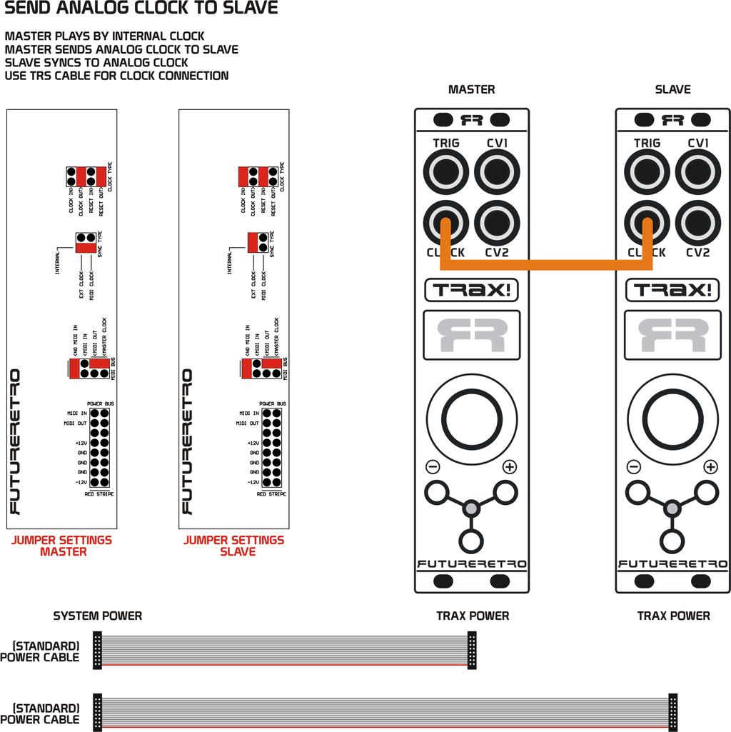
6 INPUTS AND OUTPUTS TRIGGER OUT The TRIG jack will provide a positive polarity 5ms trigger signal whenever a note is programmed to play in the Rhythm part, a Fill is activated, or when playback is stopped and you manually trigger a note. This trigger signal will range from 0 to +5v. This output should be connected to the TRIG IN of the Transient modules, or the Trigger, Gate, or even Clock input of most other modules, using a 3.5mm cable. This output will tell the Transient when to play a sound. It could also be used to trigger other percussion sound modules, trigger envelopes, S/H modules, or provide a rhythmic clock to analog sequencers. CV 1 AND 2 OUT The TRAX provides two CV outputs, both having a range from 0 to volts when scaled to the 1v/Oct standard. Each CV output has dedicated Offset and Scale trimmers accessed from the back of the unit for calibrating these control voltage signals. These outputs will update their value each time a new Trigger is generated, and should connect respectively to the CV1 and CV2 inputs on the Transient using a 3.5mm cable. When used with other modules, these CV outputs can be used to control the pitch of an oscillator, filter, amplifier or whatever you like. CLOCK The CLOCK jack on the TRAX is a stereo TRS jack. The Tip of the jack is for the Clock, while the Ring of the jack is for the Reset signal. This jack can be defined as either an output or an input by setting the appropriate jumpers on the back of the module. Turn your systems power off, before making any changes to jumper settings. The signal range of these inputs or outputs will be 0 to +5 volts. When set to be outputs, the Clock will generate the fastest clock necessary for the selected Time Signature. A Reset pulse will be generated to syncronize other devices to reset playback to the beginning of their sequence. When set to be inputs, you must make sure to also set jumpers on the back of the module to use EXT clock. Turn your systems power off, before making any changes to jumper settings. This module can then be clocked with external analog clock signals. Each time a new clock signal is received the TRAX will advance playback to the next step to play. When an external Reset signal is received, the sequencer will start playback from the beginning. 6
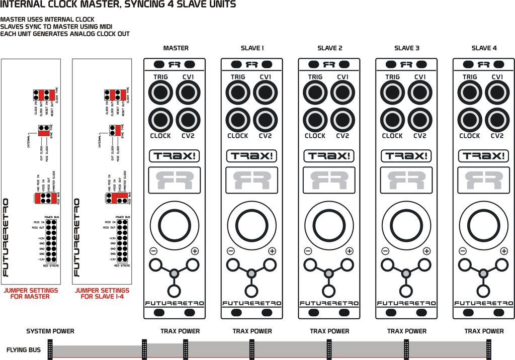
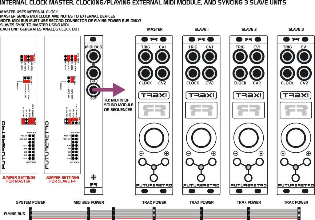
7 MIDI The TRAX uses the power bus cable to transmit MIDI to/from the MIDI BUS product, or to sync multiple TRAX sequencers together in your system using the +3.3 volt MIDI standard. In order to do this, the TRAX repurposes what the eurorack standard defines as the INT GATE line of the power bus for MIDI IN signals, and the INT CV line of the power bus for MIDI OUT signals. Since those two lines are common to all other module power ports in your system, caution must be taken that MIDI BUS settings on the TRAX do not route MIDI signals to/from the power buss using a standard ribbon power cable if other modules in the system use the INT GATE or INT CV lines for their intended or other purposes. To prevent conflicts with other signals that may be using these lines of the power bus, we recommend using our specific Flying Bus power cables when using the TRAX with the MIDI BUS product, or when simply wanting to sync multiple TRAX sequencers together in the same system. This Flying Bus power cable allows all modules connected to it to receive the proper power from the system, without connection MIDI signals to the rest of your system. MIDI will provide the best option for syncing multiple TRAX modules in your system. MIDI provides Start/Stop and Tempo control, with higher resolution clocks than an external analog clock can provide. Using MIDI also allows all slave modules to access all of the different Time Signatures, where external clocks can reliably only be divided down, meaning only slower Time Signatures are possible. Not to mention, using analog clocks to sync multiple units would require a handful of 3.5mm TRS cables, balanced multiples, and you end up with a mess of cable routing. Instead, we are introducing Flying Bus MIDI, where the ribbon cable powering the modules also provides MIDI to each module. If you simply want to sync multiple TRAX modules to one another, you can purchase the Flying Bus MIDI cable through our website. To sync one or more TRAX to other MIDI devices will require our MIDI BUS module. The MIDI BUS provides MIDI IN/OUT/THRU on 3.5mm TRS cables. Although the TRAX was designed to be a sequencer for controlling percussion units, you may find it useful as a melodic sequencer for synthesizers too. You should note that the Trig output signal is just a short 10ms pulse. Therefore it is not ideal for controlling note duration. This is fine for percussion sounds as they only need the start of their sound to be defined. Instead you may want to trigger decay-only type envelopes with the short Trig pulse to control the duration of a sound generated by other modules in your system. The TRAX can also play sound modules using MIDI. The Rhythm part will determine the MIDI note-on/off, CV1 will determine the MIDI note pitch, and CV2 will determine the MIDI velocity value. NOTE: The MIDI velocity value transmitted will be 2x the value programmed into the CV2 part providing a range. Since a MIDI note duration of only 10ms is not be very useful, the TRAX will not send a MIDI note-off message until a new MIDI note is required to play. TRAX will then send a MIDI note-off just before creating the new MIDI note-on message. This allows MIDI modules to sustain the playing of a sound until a new note needs to be played. This can creates some interesting results, since erasing rhythm steps will cause a previous note to sustain for a longer duration. Also, when the TRAX playback is stopped, and you are manually triggering the TRAX to play notes, a note will sustain infinitely until a new note is played, or until the sequencer playback starts. 7
8 JUMPER SETTINGS Before installing the TRAX in your eurorack system, it is important to understand what all the jumper settings on the back of the unit are for, and decide how you would like to use the TRAX in your setup. IMPORTANT: Make sure power is turned off, or the module is removed from your system s power before making any changes to these jumper settings. CLOCK TYPE Clock Type header defines if the front panel CLOCK jack will be used as an input or output for Clock and Reset signals. CLOCK IN Sets the Tip portion of the CLOCK jack to be an analog clock input. CLOCK OUT Sets the Tip portion of the CLOCK jack to be an analog clock output. RESET IN Sets the Ring portion of the CLOCK jack to be a reset input. RESET OUT Sets the Ring portion of the CLOCK jack to be a reset output. NOTE: Make sure both Clock and Reset jumpers are set to the same direction, either IN or OUT only. Do not try setting one to IN and the other to OUT or possible damage may occur. SYNC TYPE Sync Type header defines the clock source of the TRAX. Only one jumper location should be set at any time. INT - In this location the TRAX will use its internal clock. EXT - In this location the TRAX will use external analog clocks connected to the front panel jack. NOTE: When using EXT, you will also need to make the proper jumper settings to define the CLOCK jack for Clock In, and Reset In. MIDI In this location the TRAX will sync to external MIDI clocks. NOTE: This function requires the use of the Future Retro MIDI Bus product to gain access of MIDI In/Out signals from the TRAX. MIDI BUS MIDI BUS header defines how MIDI signals will be connected to the power bus cable! Unless you are using the TRAX with the Future Retro MIDI BUS, you should leave a single jumper on the NO MIDI IN position. NO MIDI IN A jumper should be placed in this location if you do not have the MIDI BUS product. MIDI IN Place a jumer in this location to direct MIDI IN from the MIDI BUS to the TRAX. MIDI OUT Place a jumper in this location to direct MIDI OUT from the TRAX to the MIDI BUS. MASTER CLOCK Place a jumper in this location to allow this TRAX to act as a master MIDI CLOCK. This will allow other TRAX sequencers to sync their playback to this unit via MIDI Sync when using the optional Flying Bus power cable (available through our website). The diagrams on the following pages illustrate the jumper settings required for different operations. It is very important to make sure jumper settings on your unit are identical to those shown, and that the type of power cable shown be used for that type of operation as well. 8
9 9
10 10
11 11
12 12
13 13
14 14
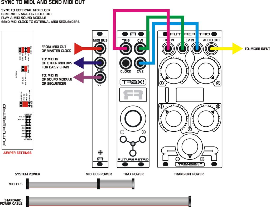
15 15
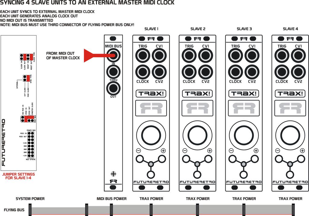
16 16

17 The MIDI BUS product conforms to the MIDI 1.0 standard, and provides +3.3 volt MIDI signals over the Power Bus Cable. Please note that standalone devices requiring their power via MIDI using the older +5 volt standard will not be compatible. For instance our 1x4 MIDI THRU box is not compatible with the MIDI BUS product. Older MIDI devices that simply require MIDI data should still be compatible. The MIDI BUS follows the TRS MIDI B Spec Class, currently supported by Arturia, Novation, and 1010 Music devices. This Spec Class requires the use of MIDI cables with internal wiring as shown in the table above. The Flying Bus cable connector, shown to the left, illustrates the location of the MIDI IN and MIDI OUT signals for the Power Bus. We provide this information here for any other manufactures who would like to adopt this method, and make products that are compatible with this new standard. 17
18 GLOBAL PARAMETERS PLAYBACK The SYNC parameter shows what will be controlling playback of this unit. The TRAX will default to the Sync type as set by the SYNC TYPE header on the back of the unit. With playback stopped, you can change the Sync value using the Parameter knob. SYNC: INT Playback will be controlled by the internal clock. Press the TAP switch to Start or Stop playback. SYNC: EXT Playback will be controlled by the analog Clock and Reset signals connected to the front panel CLOCK jack. Press the TAP switch to reset the sequencer to it s first step. SYNC: MIDI Playback will be controlled by MIDI. This mode requires the MIDI BUS product or the Flying Bus power cable. Press the TAP switch to reset the sequencer to it s first step. NOTE: While in the Playback mode, press Switch A(-) and Switch B(+) at the same time to reset values for all Part parameters. These Part parameters will reset to values similar to when the unit is first turned on. Use caution, as this will reset Rhythm, and CV patterns too. This type of reset will not change your Global parameter settings. TEMPO This parameter adjust the Tempo of the internal clock only. If Sync is set to EXT or MIDI, you will not be able to adjust the tempo using the TRAX, instead you will need to adjust the master device s tempo controlling the TRAX. There are three ways to adjust the tempo. You can rotate the Parameter knob, press Switch A(-) to decrement the tempo, press Switch B(+) to increment the tempo, or you use the TAP switch to enter the tempo by tapping twice at quarter not intervals. SWING The Swing parameter adds a human feel or shuffle to the timing of notes. The Swing amount can range from 50% to 75%. The amount can be adjusted using the Parameter knob, or you can quickly make settings by pressing TAP for 50%, Switch A(-) for 66%, or Switch B(+) for 75%. TIME SIGNATURE The TRAX provides the following time signatures: 1/4, 2/4, 3/4, 4/4, 6/4, 8/4. Time signatures may be adjusted using the Parameter knob, or more quickly and precisely using the switches. There s nothing more annoying that selecting 3/4 time signature when you are playing 4/4 time signature. Often you simply want to half or double-time the time signature to achieve a music effect. The switches allow you to do just that. Press Switch A(-) to jump from 8/4 to 4/4, 4/4 to 2/4, 2/4 to 1/4, or 6/4 to 3/4. Press Switch B(+) to jump from 1/4 to 2/4, 2/4 to 4/4, 4/4 to 8/4, or 3/4 to 6/4. Press the TAP switch to change from 3/4 to 4/4, or 6/4 to 8/4 and vice versa. MUTE The Mute parameter allows you to control if Trigger and CV output signals will be updated during playback. Press/hold Switch A(-) to temporarily mute or halt the Trigger and CV outputs. Press Switch B(+) to toggle Mute ON or OFF. Press or Press/hold TAP Switch to produce a Fill, as defined by the Fill Type parameter settings. NOTE: You can generate a Fill even if Mute is ON. 18
19 FILL TYPE The Fill Type parameter defines how Fills will be generated. The Fill Type can be adjusted using the Parameter knob, or Switch A(-) or Switch B(+). Press/hold the TAP Switch to activate a Fill as long as this switch is held. NO FILL No notes will be generated when Fill is activated. OFF STEPS Fill only the steps that are OFF in the Rhythm pattern. ON STEPS Fill only the steps that are programmed into the Rhythm pattern. ALL STEPS Fill all steps will generate a fill at the highest clock rate defined by the Time Signature selected. NOTE: When the sequencer playback is stopped, selecting any parameter mode that allows you to produce a Fill by pressing the TAP Switch, will instead allow you to use the TAP Switch to manually generate a Trigger output with CV1 and CV2 outputs producing their respective value to write. REC STEPS The Record Steps parameter defines how notes will be entered into the Rhythm pattern. The REC STEPS can be adjusted using the Parameter knob, or Switch A(-) or Switch B(+). Press/hold the TAP Switch to activate a Fill as long as this switch is held. RHYTHM New notes will be entered into the Rhythm part only when recording the Rhythm itself. CV1 New notes will be written into the Rhythm part when notes are recorded into the Rhythm or CV1 part. CV2 New notes will be written into the Rhythm part when notes are recorded into the Rhythm or CV2 part. CV1 + 2 New notes will be written into the Rhythm part when notes are recorded into the Rhythm, CV1 or CV2 part. Since each part is separate, it is often useful to record a note-on into the Rhythm part while entering notes for either of the CV parts. Use any of the CV selections to allow this for faster entering of Rhythm part information. If you wish to edit CV parts without recording new notes into the Rhythm part, set this parameter to RHYTHM. CV LINKS The CV Links allows parameters for CV1 and CV2 to link (or use) the equivalent Rhythm parameter instead of its own. CV Links can be selected using the Parameter knob, or Switch A(-) or Switch B(+). Press the TAP Switch to toggle the current link selection On or Off. Parameters that are linked to the Rhythm will be indicated as a solid white circle. Parameters that are not linked will be represented as an empty circle. When no link is underlined, the display will show OFF or ON. Use the TAP Switch to toggle this value OFF or ON. When OFF, any links set will be bypassed and each parameter will use its own parameter instead. To clear all links, hold Switch A(-) and press the TAP Switch. To set all links, hold Switch B(+) and press the TAP Switch. 19
20 CV1 AND CV2 RANGES The upper range of each CV part can be limited using the CV1 and CV2 Range settings. The Values parameter defines the max number of values each CV part can produce. Values can range from These settings are useful when you want to confine CV values to a specific range, especially when using Evolve, Phi, or Randomization. Values settings of 12, 24, 36, 48, and 60 will be ideal when using a CV to control Pitch. Range selection can be adjusted using the Parameter knob, Switch A(-) or Switch B(+). Pressing the TAP switch will reset the Range value to max setting of 64. CV1 AND CV2 SCALES Each CV output can be quantized to one of 29 musical scales. You can choose a different scale for CV1 and CV2. Scale selection can be adjusted using the Parameter knob, Switch A(-) or Switch B(+). Pressing the TAP switch will default to the Chromatic scale. In the Chromatic scale each value entered into a CV part selects a different semitone. For instance, if a CV value of 0 is equal to C, 1 is equal to C#, and 2 is equal to D. If instead you select Major as the Scale type, a value of 0 will produce a C, a value of 1 will also produce a C, and a value of 2 will produce a D. Therefore if a CV value does not exist in that scale, it will play at a lower note value that does exist in the selected scale. MASTERLOOP Masterloop defines the number of bars the sequencer will play before forcing a restart of playback, and will also generate a Reset pulse output at the Clock jack. Masterloop range can be set to OFF, meaning playback for all parts and loops is free-running, and Reset pulses will no longer occur at the Clock output jack. The Masterloop range can further be set to a value from 1-64 bars. The Masterloop parameter can be adjusted with the Parameter knob, Switch A(-) or Switch B(+). When using Switch A(-) or Switch B(+), the loop value will change in multiples of two since these are the most common musical choices. Pressing the TAP Switch will manually force an internal restarting of parameters. MIDI CHANNEL The MIDI Channel parameter defines the MIDI channel the TRAX will send MIDI data OUT when using the optional MIDI BUS product. In addition, when Sync Type is set to INT or MIDI and playback is stopped, you can also use the MIDI Channel parameter to select MIDI TO CV along with channels The MIDI Channel can be adjusted using either the Parameter knob, Switch A(-), or Switch B(+). Notice that this parameter can be adjusted from NO to When NO is selected, no MIDI data will be sent out. A selection of 1-16 will send MIDI data OUT on the selected MIDI channel. Make sure the device you are sending MIDI to is set to receive data on the same MIDI channel. Once rotated past MIDI channel 16, the parameter name will change to MIDI TO CV, and you can select channels 1-16 as the MIDI input channel to convert. Pressing the TAP switch will reset the MIDI Channel to NO, so that no MIDI will be transmitted. NOTE: You can change the MIDI channel selection on the fly while the sequencer playing, to redirect note data to different voices or sound modules. When the sequencer is stopped you can change the MIDI TO CV channel on the fly to look at and convert MIDI to Trig and CV1 and CV2 outputs. A MIDI note-on will generate a Trig out, the pitch of that note will be generated by CV1 output, and the velocity of that note will be generated by CV2. 20
21 TIP: Sync the TRAX playback to your DAW, and use the MIDI BUS to send TRAX MIDI data to your DAW to record your sequences and/or performances. You can then further edit these sequences, and save them on your computer. Better yet, try recording multiple sequences or performances from the TRAX into seperate MIDI tracks in your DAW. Assign each track to a unique MIDI channel Set the TRAX to MIDI to CV mode, then start playback of your DAW. Since you can change the MIDI to CV channel on the fly, this allows you to choose from any of the 16 tracks in the DAW you have recorded. You can use this method for different parts of a song, or simply to edit or remix bits from each sequence into something new. MIDI OFFSET MIDI note values can range from Since the CV parts only generates values in the range of 0-63, the MIDI Offset parameter allows you to shift or transpose this range to something more suitable for the MIDI module you are controlling. This Offset parameter will default to 36. The Offset value can be adjusted using the Parameter knob, Switch A(-) or Switch B(+). Pressing the TAP switch will reset the Offset value back to 36. DISPLAY SCREENSAVER The TRAX has a built in screensaver to extend the life of the display and help prevent image burn. The screensaver will turn on by default after 5 minutes or more of inactivity. This mode allows you to set the sleep time to either 5, 10, 20, 30, or 60 minutes, or simply turn this function OFF. This parameter defaults to 5 minutes. The Sleep Time can be adjusted using the Parameter knob, or Switch A(-) or Switch B(+). To wake the unit from the screensaver, simply press any of the switches. 21
22 PART PARAMETERS The parameters for the Rhythm, CV1, and CV2 parts are identical, with only slight variations between entering Rhythm information verses CV information. So let s cover those first. RHYTHM A/B This mode allows you to Record, Edit, and Erase Rhythm parts A and B while the sequencer is playing. Each part contains a single bar of music data, being up to 16 steps. First select the pattern A or B part you want to edit. RECORD A STEP - Press Switch B(+) at the moment in time you want to place a note on. ERASE A STEP - Press Switch A(-) at the moment in time a note exist that you want to erase. CREATE A FILL - Press or press/hold the TAP Switch for the duration you want to create a Fill. A Fill will play steps according to the Fill Type and affect only the Rhythm part, while CV 1 and CV2 play as programmed. RECORD REPEATED STEPS Press/hold Switch B(+), then press or press/hold the TAP Switch for the duration of notes you wish to enter. CLEAR THE ENTIRE RHYTHM PATTERN Press/hold Switch A(-), then press the TAP Switch. Notes written into the Rhythm part will be indicated as a solid white circle. Steps that are OFF will be represented as an empty circle. As the sequence plays, a cursor will blink under the step currently playing. CV1 AND CV2 A/B This mode allows you to Record, Edit, and Clear CV1 or CV2 parts A and B while the sequencer is playing. Each part contains a single bar of music data, being up to 16 steps. First select the CV1 or CV2 pattern A or B part you want to edit. The upper right-hand corner of the display will show the current value to write. This value can be adjusted using the Parameter knob, or by using the Get A Step Value described below. RECORD A VALUE - Press Switch B(+) at the moment in time you want to place the current value in the sequence. GET A STEP VALUE Press Switch A(-) at the moment in time you want to get the currently playing step s value. This value will then be assigned as the value to write for new values entered, or when a Fill is generated. If you continue holding Switch A(-), you can then use the Parameter knob to edit the value of the step you got the value from, as long as you are not playing an evolution, randomized, or phi type of pattern. CREATE A FILL - Press or hold the TAP Switch for the duration you want to create a Fill. A Fill will force all CV1 or CV2 output values to the current value to write for that part. This happens independently, and does not affect both CV parts simultaneously. While a Fill is occurring, you may choose to adjust the value to write or Fill using the Parameter knob. 22
23 SET ALL STEPS TO THE CURRENT VALUE TO WRITE Press/hold Switch B(+), then press or the TAP Switch. CLEAR THE RHTYHM PATTERN Press/hold Switch A(-), then press the TAP Switch. This feature is available only when the REC STEPS parameter is set to the CV currently active. The Rhythm s PLAY MODE will define if pattern A, B, or both A and B will be cleared. Values written into the CV parts will be indicated as vertical white bars. As the sequence plays, a cursor will blink under the step currently playing. PLAY MODE The Play Mode defines how the Rhythm, CV1, and CV2 will use their A/B parts. Play Mode selection can be adjusted using the Parameter knob, Switch A(-) or Switch B(+). Pressing the TAP switch will default the Play Mode to pattern A. A This part uses pattern A only B This part uses pattern B only A+B This part will play pattern A and then play pattern B RANDOMIZE A+B This part will randomly select and play the data from either pattern A or pattern B. Writing or copying the same step value to both patterns will cause that step to always play the programmed step value. Only steps written different from one another will appear to be randomized. EVOLVE This unique mode can analyze the difference between patterns A and B, and automatically generate new pattern variations. RANDOM/PHI This unique mode allows you to either randomize the data for a pattern, and/or apply Phi (the golden ratio) to data that has been randomized, or apply it to pattern A to generate a multitude of new pattern possibilities. COPY/PASTE, EVOLUTION, RAND/PHI This parameter page will change depending on the Play Mode selected for the respective Rhythm, CV1, or CV2 part. COPY/PASTE This parameter page will be shown when A, B, A+B, or Randomize A+B are selected for the respective part s Play Mode. To copy data from pattern A to pattern B, press and hold Switch A(-), and then press Switch B (+). To copy data from pattern B to pattern A, press and hold Switch B(+), and then press Switch A(-). EVOLUTION This parameter page will be shown when Evolve is selected for the respective part s Play Mode. Whenever Evolve is selected as the Play Mode type, the evolution amount will be calculated and pattern A will automatically be selected to play, as this is the first step in our evolution. 23
24 Pressing Switch B(+) will advance to the next evolution to play. If pattern A was playing, pattern B will now be playing, as that would be the second step in our evolution. Each additional press of Switch B(+) will access a new evolution of the pattern based on the calculated differences between pattern A and B. The display will change to show the new output for each evolution. Pressing Switch A(-) will advance through evolutions in the opposite direction. And again the display will change to show the new output for current evolution. Pressing the TAP Switch will do two things. It will recalculate the evolution step amount based on patterns A and B, and it will reload pattern A as the current evolution. NOTE: Since Evolutions are calculated when Evolve is first selected as the Play Mode type, or if the TAP Switch is pressed while on the Evolution page, this then allows you to go edit pattern A or pattern B without the audience hearing your changes. Instead, these changes will be introduced to your audience when patterns A or B are selected for the Play Mode, or if you reselect Evolve as the Play Mode type, or press the TAP Switch to recalculate the Evolve amount, this will then produce new Evolution patterns. TIP: Selecting new evolutions works really well when taking a DJ s approach to introducing a new song. Try selecting a new evolution for a small section in time, before going back to the previous evolution. Let your audience become familiar with parts of the new evolution before introducing the whole pattern to them. Or use this feature as a type of variations fill for small sections of the pattern. New evolutions may also be automatically generated each time the respective part s LOOP 2 BARS loop point is reached, as long as the REGEN loop is set to anything other than OFF. When selecting evolutions with Switch A(-) or Switch B(+), if you hold that switch down you then have the ability to copy the current evolution to either pattern A or pattern B. This works similar to the Copy/Paste feature, where if you are holding Switch A(-), and want to copy the current evolution to pattern A, you would press the TAP Switch. If instead you wanted to copy the current evolution to pattern B, you would instead press the Switch B(+). Or if instead you are holding Switch B(+) and want to copy the current evolution to pattern A, you would press Switch A(-). To copy the current evolution to pattern B(+), you would press the TAP Switch. One thing to keep in mind is if you copy the same data to both pattern A and B, no evolutions can take place as there is no difference between the two patterns. RAND/PHI The Randomize / Phi mode shares quite a few similarities with the Evolve mode. When RAND/PHI is selected in the Play Mode, pattern A of the respective part will be loaded into a temporary pattern buffer to play and process. Pressing Switch A(-) will load a randomized pattern into a temporary pattern buffer to play. Pressing Switch B(+) will take whatever is in the temporary buffer (either pattern A or the randomized pattern), and apply Phi (or the golden ratio) to pattern to create a new variation. Pressing the TAP Switch while in RAND/PHI will cause pattern A to be reloaded into the temporary buffer to play and process. 24
25 When you randomize a pattern, if you hold Switch A(-), you can then copy this randomized pattern to pattern A by pressing the TAP Switch, or to pattern B by pressing Switch B(+). Similarly when you apply Phi to a pattern, if you continue to hold Switch B(+), and then press Switch A(-) the newly generated Phi pattern will be copied to pattern A, or if you press the TAP Switch instead this new Phi pattern will be copied to pattern B. NOTE: Randomized patterns are less likely to make sense to your audience, however they can be used as a short randomized fill, then press the TAP Switch to return to the original pattern A. Or you may simply want to continuously randomize the data until something you like happens, and then you can copy that to pattern A or B. The display will update to show the current outcome of your latest randomization or Phi process. This gives you the ability to foresee what is about to play, and make further changes should you choose. REMIX Remix is a unique feature that provides 256 variations in the order steps are selected to play for the respective part. The Remix value can be changed using the Parameter knob, Switch A(-) or Switch B(+). Pressing the TAP Switch will toggle the Remix function ON and OFF. You can leave Remix ON, and select different Remix values to change how the pattern plays. Or you may choose to turn the Remix ON for small sections where you want to create a short variation or fill. DIRECTION This feature defines which Direction the respective part will play. The Direction parameter can be adjusted with the Parameter knob, Switch A(-) or Switch B(+). Pressing the TAP Switch will reset the Direction to UP. DOWN Starts playback on the first step, and then counts backwards through steps. UP Starts playback on the first step, incrementing up through the remaining steps. UP/DOWN Starts playback on the first step, incrementing up through the steps, then restarting at the first step, and moving backwards through the steps. RANDOMIZE Randomly selects a step to play OFFSET The Offset function affects the step the respective part will begin playing from. The offset value can range from The Offset parameter can be adjusted with the Parameter knob, Switch A(-) or Switch B(+). Pressing the TAP Switch will reset the Offset value to 0. LOOP 1 STEPS Loop 1 defines the number of steps the respective part will play before returning to the first step. Loop 1 can be set from 1-16 steps. The Loop 1 parameter can be adjusted with the Parameter knob, Switch A(-) or Switch B(+). Pressing the TAP Switch will reset Loop 1 to a value of 16 or 12 steps depending on the type time signature selected. NOTE: When Loop 1 is reached, if the UP/DOWN direction is selected, it will cause this part to change direction. However, if Loop 1 is set to 16 steps, you will need to adjust Loop 2 to a value of 2 or more bars for the UP/DOWN to have any affect. 25
26 LOOP 2 BARS Loop 2 defines the number of bars the respective part will play before forcing Loop 1 to restart, and also defines the point which A+B, Evolution, and Phi processes will advance to their next pattern. Loop 2 can be set from 1-64 bars. The Loop 2 parameter can be adjusted with the Parameter knob, Switch A(-) or Switch B(+). When using Switch A(-) or Switch B(+), the loop value will change in multiples of two since these are the most common musical choices. Pressing the TAP Switch will reset Loop 2 to a value of one bar. REGEN Regen is a third loop point, that defines how many bars will occur before both Loop 1 and Loop 2 are reset forcing the respective part to begin playing from the first step, and also causing A+B patterns to begin playing pattern A, or causing the Evolution and Phi patterns to be recalculated and begin playing from pattern A again. The Regen range can be set to OFF, meaning Evolution and Phi patterns will not automatically generate a new pattern each time Loop 2 is reached. Instead, Evolution and Phi patterns can be manually stepped through by the user. The Regen range can further be set to a value from 1-64 defining the number of bars regenerating patterns will occur. The Regen parameter can be adjusted with the Parameter knob, Switch A(-) or Switch B(+). When using Switch A(-) or Switch B(+), the value will change in multiples of two since these are the most common musical choices. Pressing the TAP Switch will reset Regen to OFF. 26

27 CALIBRATION The TRAX has a special Calibration mode to help you adjust your CV outputs to the proper levels. These levels are set at the factory when the module was built, however over time you may find these outputs need to be recalibrated. To enter Calibration mode, start with your system powered OFF. Press and hold the Parameter switch on the TRAX and turn your system s power ON. Hold this switch until the display shows CALIBRATE, then you may release the Parameter switch. Connect a short 3.5mm cable from either CV1 or CV2 output on the TRAX to a precision voltmeter. Press Switch A(-), and both CV1 and CV2 outputs will produce a DAC value of 0, while the TRIG jack will generate a trigger out signal. At this point you should adjust the Offset trimmer (for the corresponding CV on the back of the TRAX), so the CV output reads volts. Press Switch B(+), and both CV1 and CV2 outputs will produce a DAC value 5 octaves higher, while the TRIG jack will generate a trigger out signal. At this point you should adjust the Scale trimmer (for the corresponding CV on the back of the TRAX), so the CV output reads volts. Once calibration is complete, press the Parameter switch to exit this mode and return to the parameter menu. 27
28 TROUBLESHOOTING Always use caution when handling the TRAX. Make sure to discharge yourself of any static electricity before touching the unit. When installing and removing the module from your system, hold the unit at the edge of the front panel to avoid your fingers from coming in contact with the circuitry. Keep your original packaging in case you ever need to ship your product. This unit should always be placed in an anti-static bag during shipping. Pay very close attention when installing the TRAX into your system, so that the red-strip of the power ribbon cable is aligned with the -12v on both the TRAX and your system s power distribution connector. When removing modules from your system, it is a good idea to inspect the connectors of the power bus cable to confirm the connector has not been abused to the point it is pulling apart. Make sure you know how much current your system can provide for each voltage level, and how much current the modules in your system are drawing from the power supply. If your system is unable to provide enough current for each module in your system, obviously something is not going to work as expected or perhaps at all. If your unit ever behaves in an unexpected way, turn the unit off, and then back on again. If you have other questions or you experience problems not addressed in this manual, please check the Support page of our web site: or try downloading the latest version of this manual. WARRANTY This product comes with a 1-year warranty covering all parts and labor. Register your product at within 30 days of your purchase to validate your warranty. You will find the serial number for your product listed on both the outside of the original product box, as well as on the back side of the module. SPECIFICATIONS Eurorack Width: 6HP Dimensions: [1.20" (W) x 5.07" (H) x 1.50" (D)] or [30.40mm (W) x mm (H) x 38.10mm (D)] Boxed Weight: 0.4 lbs. +12v Supply Current Draw: 90mA (typical) -12v Supply Current Draw: 9mA (typical) +5v Supply Current Draw: 0mA 28
ALGORHYTHM. User Manual. Version 1.0
 !! ALGORHYTHM User Manual Version 1.0 ALGORHYTHM Algorhythm is an eight-step pulse sequencer for the Eurorack modular synth format. The interface provides realtime programming of patterns and sequencer
Shifty Manual v1.00. Shifty. Voice Allocator / Hocketing Controller / Analog Shift Register
 Shifty Manual v1.00 Shifty Voice Allocator / Hocketing Controller / Analog Shift Register Table of Contents Table of Contents Overview Features Installation Before Your Start Installing Your Module Front
Shifty Manual. Shifty. Voice Allocator Hocketing Controller Analog Shift Register Sequential/Manual Switch. Manual Revision:
 Shifty Voice Allocator Hocketing Controller Analog Shift Register Sequential/Manual Switch Manual Revision: 2018.10.14 Table of Contents Table of Contents Compliance Installation Installing Your Module
// K4815 // Pattern Generator. User Manual. Hardware Version D-F Firmware Version 1.2x February 5, 2013 Kilpatrick Audio
 // K4815 // Pattern Generator Kilpatrick Audio // K4815 // Pattern Generator 2p Introduction Welcome to the wonderful world of the K4815 Pattern Generator. The K4815 is a unique and flexible way of generating
VARIGATE 4+ MANUAL V.1
 www.malekkoheavyindustry.com 814 SE 14TH AVENUE PORTLAND OR 97214 USA TABLE OF CONTENTS SPECIFICATIONS 1 INSTALLATION 2 DESCRIPTION 3 OVERVIEW 4-5 PROGRAMMING GATES PER STEP 6 PROGRAMMING CV/NOTES PER
randomrhythm Bedienungsanleitung User Guide
 randomrhythm Bedienungsanleitung User Guide EN Foreword Whether random really exists or is just an illusion, shall be discussed by philosophers and mathematicians. At VERMONA, we found a possibility to
R H Y T H M G E N E R A T O R. User Guide. Version 1.3.0
 R H Y T H M G E N E R A T O R User Guide Version 1.3.0 Contents Introduction... 3 Getting Started... 4 Loading a Combinator Patch... 4 The Front Panel... 5 The Display... 5 Pattern... 6 Sync... 7 Gates...
Modcan Touch Sequencer Manual
 Modcan Touch Sequencer Manual Normal 12V operation Only if +5V rail is available Screen Contrast Adjustment Remove big resistor if using with PSU with 5V rail Jumper TOP VEIW +5V (optional) +12V } GND
fxbox User Manual P. 1 Fxbox User Manual
 fxbox User Manual P. 1 Fxbox User Manual OVERVIEW 3 THE MICROSD CARD 4 WORKING WITH EFFECTS 4 MOMENTARILY APPLY AN EFFECT 4 TRIGGER AN EFFECT VIA CONTROL VOLTAGE SIGNAL 4 TRIGGER AN EFFECT VIA MIDI INPUT
Quad Clock Distributor (QCD) from 4ms Company
 from 4ms Company") Quad Clock Distributor (QCD) from 4ms Company Eurorack Module User Manual v1.0 (2013-12-09) The Quad Clock Distributor (QCD) from 4ms Company is a four channel Voltage Controlled Clock Divider/Multiplier
Quad Clock Distributor (QCD) from 4ms Company Eurorack Module User Manual v1.0 (2013-12-09) The Quad Clock Distributor (QCD) from 4ms Company is a four channel Voltage Controlled Clock Divider/Multiplier
// K4815 // Pattern Generator. User Manual. Hardware Version D/E Firmware Version 1.1x February 16, 2011 Kilpatrick Audio
 // K4815 // Pattern Generator Kilpatrick Audio // K4815 // Pattern Generator 2p Introduction Welcome to the wonderful world of the K4815 Pattern Generator. The K4815 is a unique and flexible way of generating
StepSequencer64 J74 Page 1. J74 StepSequencer64. A tool for creative sequence programming in Ableton Live. User Manual
 StepSequencer64 J74 Page 1 J74 StepSequencer64 A tool for creative sequence programming in Ableton Live User Manual StepSequencer64 J74 Page 2 How to Install the J74 StepSequencer64 devices J74 StepSequencer64
Intelligent Quantizer and Interval Generator
 µscale Intelligent Quantizer and Interval Generator Manual Revision: 2018.02.16 Table of Contents Table of Contents Overview Features Installation Before Your Start Installing Your Module Front Panel Controls
Tetrapad Manual. Tetrapad. Multi-Dimensional Performance Touch Controller. Firmware: 1.0 Manual Revision:
 Tetrapad Multi-Dimensional Performance Touch Controller Firmware: 1.0 Manual Revision: 2017.11.15 Table of Contents Table of Contents Overview Installation Before Your Start Installing Your Module Panel
III Phrase Sampler. User Manual
 III Phrase Sampler User Manual Version 3.3 Software Active MIDI Sync Jun 2014 800-530-4699 817-421-2762, outside of USA mnelson@boomerangmusic.com Boomerang III Phrase Sampler Version 3.3, Active MIDI
QUAD ENVELOPE MANUAL V.1
 www.malekkoheavyindustry.com 814 SE 14TH AVENUE PORTLAND OR 97214 USA TABLE OF CONTENTS SPECIFICATIONS 1 INSTALLATION 2 DESCRIPTION 3 CONTROLS 4-6 MEASUREMENTS 7 USING QUAD ENVELOPE WITH VARIGATE 8+ AND
User Guide Version 1.1.0
 obotic ean C R E A T I V E User Guide Version 1.1.0 Contents Introduction... 3 Getting Started... 4 Loading a Combinator Patch... 5 The Front Panel... 6 On/Off... 6 The Display... 6 Reset... 7 Keys...
User Guide. Version 2.0.0
 II User Guide Version 2.0.0 Contents Introduction... 3 What s New in Step Note Recorder II?... 3 Getting Started... 4 The Front Panel... 5 The Sequence... 5 The Piano Roll... 6 The Data Lane... 7 Velocity...
Edit Menu. To Change a Parameter Place the cursor below the parameter field. Rotate the Data Entry Control to change the parameter value.
 The Edit Menu contains four layers of preset parameters that you can modify and then save as preset information in one of the user preset locations. There are four instrument layers in the Edit menu. See
multitrack sequencer USER GUIDE Social Entropy Electronic Music Instruments
 multitrack sequencer Social Entropy Electronic Music Instruments IMPORTANT SAFETY AND MAINTENANCE INSTRUCTIONS TABLE OF CONTENTS BACKGROUND... 1 CONCEPTS... 2 DIAGRAM CONVENTIONS... 3 THE BASICS WHAT
Synthesis Technology E102 Quad Temporal Shifter User Guide Version 1.0. Dec
 Synthesis Technology E102 Quad Temporal Shifter User Guide Version 1.0 Dec. 2014 www.synthtech.com/euro/e102 OVERVIEW The Synthesis Technology E102 is a digital implementation of the classic Analog Shift
Polyend Poly Polyphonic MIDI to CV Converter User Manual
 Polyend Poly Polyphonic MIDI to CV Converter User Manual Made in Poland polyend.com Polyend Poly Polyphonic MIDI to CV Converter in the Eurorack format Poly is probably the easiest entry point for exploring
COPYING A PATTERN...35
 f TABLE OF CONTENTS INTRODUCTION...5 WELCOME TO THE SR18 DRUM MACHINE!...5 GROUND RULES...5 CONNECTION DIAGRAM...8 TOP PANEL PHYSICAL LAYOUT...9 GENERAL CONTROLS...9 NAVIGATION BUTTONS...10 MODE BUTTONS...10
American DJ. Show Designer. Software Revision 2.08
 American DJ Show Designer Software Revision 2.08 American DJ 4295 Charter Street Los Angeles, CA 90058 USA E-mail: support@ameriandj.com Web: www.americandj.com OVERVIEW Show Designer is a new lighting
oberkorn3 analogue sequencer user manual analogue sequencer user manual ANALOGUE SOLUTIONS oberkorn mkiii e&oe (c)
") oberkorn3 analogue sequencer user manual analogue sequencer user manual ANALOGUE SOLUTIONS oberkorn mkiii e&oe (c) 10-2006 1 Contents Intro - OBERKORN - Professional Analogue Sequencer...4 About Analogue
oberkorn3 analogue sequencer user manual analogue sequencer user manual ANALOGUE SOLUTIONS oberkorn mkiii e&oe (c) 10-2006 1 Contents Intro - OBERKORN - Professional Analogue Sequencer...4 About Analogue
y POWER USER MUSIC PRODUCTION and PERFORMANCE With the MOTIF ES Mastering the Sample SLICE function
 y POWER USER MUSIC PRODUCTION and PERFORMANCE With the MOTIF ES Mastering the Sample SLICE function Phil Clendeninn Senior Product Specialist Technology Products Yamaha Corporation of America Working with
Oberkorn User Manual. Analogue Sequencer. Analogue Solutions
 Oberkorn User Manual Analogue Sequencer Analogue Solutions CONTENTS What is an analogue sequencer?... 4 That s all very well (and technical) but what would I use it for?... 4 ABOUT THIS MANUAL AND ABOUT
Noise Tools 1U Manual. Noise Tools 1U. Clock, Random Pulse, Analog Noise, Sample & Hold, and Slew. Manual Revision:
 Noise Tools 1U Clock, Random Pulse, Analog Noise, Sample & Hold, and Slew Manual Revision: 2018.05.16 Table of Contents Table of Contents Overview Installation Before Your Start Installing Your Module
QUAD LFO MANUAL V SE 14TH AVENUE PORTLAND OR USA
 www.malekkoheavyindustry.com 814 SE 14TH AVENUE PORTLAND OR 97214 USA TABLE OF CONTENTS SPECIFICATIONS 1 INSTALLATION 2 DESCRIPTION 3 CONTROLS 4-6 USING QUAD LFO WITH VARIGATE 8+ AND VARIGATE 4+ 7 WARRANTY
Four Head dtape Echo & Looper
 Four Head dtape Echo & Looper QUICK START GUIDE Magneto is a tape-voiced multi-head delay designed for maximum musicality and flexibility. Please download the complete user manual for a full description
Noise Tools 1U Manual. Noise Tools 1U. Clock, Random Pulse, Analog Noise, Sample & Hold, and Slew. Manual Revision:
 Noise Tools 1U Clock, Random Pulse, Analog Noise, Sample & Hold, and Slew Manual Revision: 2018.09.13 Table of Contents Table of Contents Compliance Installation Before Your Start Installing Your Module
To ensure long, trouble-free operation, please read this manual carefully. Precautions
 Thank you purchasing the Korg ELECTRIBE M EM-1. In order to enjoy long and trouble-free use, please read this manual carefully and use the instrument correctly. E 1 To ensure long, trouble-free operation,
LS1lightstrip User s Manual. Introduction Care and feeding Specifications. soundmachines user manual 1 LS1lightstrip
 User s Manual Introduction Care and feeding Specifications soundmachines user manual 1 Introduction The is a capacitive slider that will generate CV and GATE signals along with the movement of your finger
MantaMate User Manual. Snyderphonics
 MantaMate User Manual Snyderphonics Version 0.7, July 30, 2017 Contents Preface 1 Setting up the MantaMate 1 1.1 Connecting Power......................... 1 1.2 Output Voltage Range Jumper..................
First things first. Visit us:
 Flight Plan v. 1.2 First things first RTFM be so kind and read the manual. It will provide you with the information you need to fully indulge in the module you just purchased for which we like to thank
ADE-32 OCTOCONTROLLER
 ADE-32 OCTOCONTROLLER Control, Modulation, Triggering and Pattern module with 12 Output Types individually assignable to 8 simultaneous Outputs. USER GUIDE 2016 Abstract Data Ltd. http://www.abstractdata.biz
For example, an indication of Range: 60, 67, 72, 75 (Hz) means that 60 Hz is the default value.
 means that 60 Hz is the default value.") Owner s Manual This manual explains how to use an MV-8000 in which System Program Version 3.0 is installed. About the Symbols and icons in this manual Text in square brackets [ ] refers to buttons on the
Owner s Manual This manual explains how to use an MV-8000 in which System Program Version 3.0 is installed. About the Symbols and icons in this manual Text in square brackets [ ] refers to buttons on the
Limited WARRANTY: Make Noise implies and accepts no responsibility for harm to person or apparatus caused through operation of this product.
 v2.5 2 BRAINS Limited Warranty ----------------------------------------------------3 Installation --------------------------------------------------4 Jumpers and Cable Connections --------------------------------5
Software version 2.0. Operator's Manual
 3 Software version 2.0 Operator's Manual By Roger Linn Copyright 1987, 1988, 1989 Akai Electric Co., LTD. Document revision date: April 20, 1989 4 READ THIS BEFORE YOU START! Power requirements Power requirements
Using Impact LX+ with Reason
 www.nektartech.com Using Impact LX+ with Reason Reason Integration Setup and Configuration The Impact LX+ Reason Integration is compatible with all Reason products from version 5 or higher. These instructions
Limited WARRANTY: Make Noise implies and accepts no responsibility for harm to person or apparatus caused through operation of this product.
 v2.4 1 BRAINS Limited Warranty: ----------------------------------------------------2 Installation: --------------------------------------------------3 Jumpers and Cable Connections: --------------------------------4
TEMPI FCC: Limited Warranty:
 v2.5 1 TEMPI FCC: ------------------------------------------------------------------2 Limited Warranty: -------------------------------------------------3 Installation: ----------------------------------------------------------4
XYNTHESIZR User Guide 1.5
 XYNTHESIZR User Guide 1.5 Overview Main Screen Sequencer Grid Bottom Panel Control Panel Synth Panel OSC1 & OSC2 Amp Envelope LFO1 & LFO2 Filter Filter Envelope Reverb Pan Delay SEQ Panel Sequencer Key
Tiptop audio z-dsp.
 Tiptop audio z-dsp www.tiptopaudio.com Introduction Welcome to the world of digital signal processing! The Z-DSP is a modular synthesizer component that can process and generate audio using a dedicated
Description. Never run out of envelopes again.
 Contour Description Never run out of envelopes again. Contour is a quad envelope generator. Each channel has looping, CV over attack and decay, as well as unique chaining capabilities. This makes for the
Start/Stop works in each mode, and puts the pattern back to the starting point step 1 of the current pattern.
 Sequencer Modes In all six modes the playing of the sequencer is guaranteed. You can change the modes, while the sequencer is running. Switching into another mode, takes place after the last step of the
NoteMix Player Note Mixer/Shifter/Splitter/Filter with Snapshot Morphing Rack Extension for Propellerhead Reason
 NoteMix Player Note Mixer/Shifter/Splitter/Filter with Snapshot Morphing Rack Extension for Propellerhead Reason USER MANUAL version 1.0.0 NoteMix User Manual www.retouchcontrol.com Page 1 of 26 Table
BodyBeat Metronome Instruction Manual
 BodyBeat Metronome Instruction Manual Peterson Electro-Musical Products, Inc. 2013 Power The StroboPlus contains a powerful internal rechargeable Lithium-Ion battery. Before initial use, we recommend that
Revision 1.2d
 Specifications subject to change without notice 0 of 16 Universal Encoder Checker Universal Encoder Checker...1 Description...2 Components...2 Encoder Checker and Adapter Connections...2 Warning: High
RE-303 CPU. SONIC-POTIONS!!! PRELIMINARY DRAFT!!! v WORK IN PROGRESS
 RE-303 CPU SONIC-POTIONS!!! PRELIMINARY DRAFT!!! v 0.911 WORK IN PROGRESS Intro... 3 Quickstart... 3 The random way... 3 The manual way...3 Control scheme... 4 Pattern Write Mode... 4 Auto Exit... 4 Normal
Model 5240 Digital to Analog Key Converter Data Pack
 Model 5240 Digital to Analog Key Converter Data Pack E NSEMBLE D E S I G N S Revision 2.1 SW v2.0 This data pack provides detailed installation, configuration and operation information for the 5240 Digital
S I N E V I B E S FRACTION AUDIO SLICING WORKSTATION
 S I N E V I B E S FRACTION AUDIO SLICING WORKSTATION INTRODUCTION Fraction is a plugin for deep on-the-fly remixing and mangling of sound. It features 8x independent slicers which record and repeat short
Rhythm. Pattern Generator
 Rhythm Pattern Generator Description The Rhythm is a 4 channel pattern generator with BPM display. It ships with a multitude of genre-oriented rhythms that can be altered on a per channel basis. With each
Solid State Logic S O U N D V I S I O N
 Solid State Logic S O U N D V I S I O N SUPERANALOGUE X - R A C K Super-Analogue Outboard XR622 X-Rack Master Module User s Guide This documentation package contains the User s Guide for your new X-Rack
To ensure long, trouble-free operation, please read this manual carefully. Precautions
 Thank you purchasing the Korg ELECTRIBE A EA-. In order to enjoy long and trouble-free use, please read this manual carefully and use the instrument correctly. E To ensure long, trouble-free operation,
SATELLITE. Universal CV Generator. Operation Manual. v2.1_ Copyright 2017 Rossum Electro-Music LLC
 SATELLITE Universal CV Generator Operation Manual v2.1_060117 Copyright 2017 Rossum Electro-Music LLC www.rossum-electro.com Contents 1. Introduction 3 2. Module Installation 4 3. Overview 5 4. How to
FRQM-2 Frequency Counter & RF Multimeter
 FRQM-2 Frequency Counter & RF Multimeter Usage Instructions Firmware v2.09 Copyright 2007-2011 by ASPiSYS Ltd. Distributed by: ASPiSYS Ltd. P.O.Box 14386, Athens 11510 (http://www.aspisys.com) Tel. (+30)
Dave Jones Design Phone: (607) Lake St., Owego, NY USA
 Lake St., Owego, NY USA") Manual v1.00a June 1, 2016 for firmware vers. 2.00 Dave Jones Design Phone: (607) 687-5740 34 Lake St., Owego, NY 13827 USA www.jonesvideo.com O Tool Plus - User Manual Main mode NOTE: New modules are
Manual v1.00a June 1, 2016 for firmware vers. 2.00 Dave Jones Design Phone: (607) 687-5740 34 Lake St., Owego, NY 13827 USA www.jonesvideo.com O Tool Plus - User Manual Main mode NOTE: New modules are
Plog rev 1.0 MANUAL Overview
 Overview The Intellijel Plog is a voltage controllable digital logic device designed for musical applications. It is primarily intended to create controllable patterns from gate/ pulse sources like clocks
KAMIENIEC. analog resonant phase rotator. Model of operator s manual rev. 1977/1.0
 KAMIENIEC analog resonant phase rotator operator s manual rev. 1977/1.0 Model of 1977 module explained 20 SALUT Thank you for purchasing this Xaoc Devices product. Kamieniec is an analog signal processing
MANUAL v.3 CONTACT MORE THAN LOGIC. UNITING ART + ENGINEERING.
 MANUAL v.3 MORE THAN LOGIC. UNITING ART + ENGINEERING. CONTACT email: info@meris.us phone: 747.233.1440 website: www.meris.us TABLE OF CONTENTS SECTION 1 PG. 1 FRONT PANEL CONTROLS SECTION 2 PG. 2-4 GLOBAL
Please contact with any questions, needs & comments... otherwise go MAKE NOISE.
 soundhack ECHOPHON Limited WARRANTY: Make Noise warrants this product to be free of defects in materials or construction for a period of two years from the date of manufacture. Malfunction resulting from
YAMAHA AUTHORIZED PRODUCT MANUAL DIGITAL RHYTHM PROGRAMMER
 YAMAHA AUTHORIZED PRODUCT MANUAL DIGITAL RHYTHM PROGRAMMER YAMAHA DIGITAL RHYTHM PROGRAMMER OWNER S MANUAL Congratulations on your purchase of the Yamaha RX5 Digital Rhythm Programmer! Your RX5 has been
Sequencer 1 User s Guide
 Sequencer 1 User s Guide Audio Damage, Inc. For Firmware Version 1.5.0 22 December 2016 The information in this document is subject to change without notice and does not represent a commitment on the part
5U Oakley Modular Series
 Oakley Sound Systems 5U Oakley Modular Series VC-LFO Low Frequency Oscillator PCB Issue 2 User Manual V2.0.04 Tony Allgood B.Eng PGCE Oakley Sound Systems CARLISLE United Kingdom The suggested panel layout
NAVIGATOR OWNER S MANUAL
 OWNER S MANUAL UNCHARTED WATERS, NEW HORIZONS Making shapes spin and move is notoriously difficult for pattern synthesis based only on oscillators synchronized to horizontal and vertical frequency ranges.
USER GUIDE V 1.6 ROLLERCHIMP DrumStudio User Guide page 1
 USER GUIDE V 1.6 ROLLERCHIMP 2014 DrumStudio User Guide page 1 Table of Contents TRANSPORT... 3 SONG NAVIGATOR / SECTION EDITING...4 EDITOR...5 TIMING OPTIONS...6 PLAYBACK OPTIONS... 7 RECORDING OPTIONS...8
DP1 DYNAMIC PROCESSOR MODULE OPERATING INSTRUCTIONS
 DP1 DYNAMIC PROCESSOR MODULE OPERATING INSTRUCTIONS and trouble-shooting guide LECTROSONICS, INC. Rio Rancho, NM INTRODUCTION The DP1 Dynamic Processor Module provides complete dynamic control of signals
Limited WARRANTY: Make Noise implies and accepts no responsibility for harm to person or apparatus caused through operation of this product.
 Rosie Limited WARRANTY: Make Noise warrants this product to be free of defects in materials or construction for a period of one year from the date of purchase (proof of purchase/invoice required). Malfunction
CIRCADIAN RHYTHMS User Manual
 CIRCADIAN RHYTHMS User Manual Circadian Rhythms for modular music composers INDEX Introduction... p.02 Section 1 Quick Start Tutorials... p.03 1 - Vertical View Basics... p.03 2 - Other Views... p.07 3
DMX48. User s instruction manual. 24 Channel DMX controller
 WWW.LIGHTEMOTIONS.COM.AU DMX48 24 Channel DMX controller User s instruction manual This manual contains important information about the safe installation and use of this product Please read this instruction
Table of Contents. Volante - Magnetic Echo Machine FRONT PANEL REAR PANEL FOOTSWITCHES SOUND ON SOUND LIVE EDIT FUNCTIONS EXPRESSION PEDAL
 USER MANUAL Table of Contents FRONT PANEL REAR PANEL FOOTSWITCHES SOUND ON SOUND LIVE EDIT FUNCTIONS EXPRESSION PEDAL POWER UP MODES MULTISWITCH PLUS FACTORY RESET MIDI IMPLEMENTATION OUTPUT MODES SIGNAL
LS9 StageMix V6 User Guide
 Welcome: Thank you for downloading the LS9 StageMix ipad app for the Yamaha LS9 digital mixing consoles. The latest firmware version for LS9 can be downloaded from www.yamahaproaudio.com StageMix is an
USER MANUAL FOR THE ANALOGIC GAUGE FIRMWARE VERSION 1.0
 by USER MANUAL FOR THE ANALOGIC GAUGE FIRMWARE VERSION 1.0 www.aeroforcetech.com Made in the USA! WARNING Vehicle operator should focus primary attention to the road while using the Interceptor. The information
DLM471S-5.1 MULTICHANNEL AUDIO LEVEL MASTER OPERATION MANUAL IB B. (Mounted in RMS400 Rack Mount & Power Supply) (One of 4 Typical Cards)
 (One of 4 Typical Cards)") DLM471S-5.1 (Mounted in RMS400 Rack Mount & Power Supply) MULTICHANNEL AUDIO LEVEL MASTER (One of 4 Typical Cards) OPERATION MANUAL IB6432-02B TABLE OF CONTENTS PAGE 1.0 GENERAL DESCRIPTION 2 2.0 INSTALLATION
DLM471S-5.1 (Mounted in RMS400 Rack Mount & Power Supply) MULTICHANNEL AUDIO LEVEL MASTER (One of 4 Typical Cards) OPERATION MANUAL IB6432-02B TABLE OF CONTENTS PAGE 1.0 GENERAL DESCRIPTION 2 2.0 INSTALLATION
Audio Interface II Manual. Audio Interface II. Eurorack <-> Line Level Audio Interface. Manual Revision: 1.0
 Audio Interface II Eurorack Line Level Audio Interface Manual Revision: 1.0 Overview The Audio Interface II allows you to interface your Eurorack modular system to the pro balanced line level world
Pressure Points. v. 2.5
 Pressure Points v. 2.5 2 Pressure Points FCC-------------------------------------------------------------------3 Limited Warranty ----------------------------------------------------4 Installation ----------------------------------------------------5
Table of Contents. Volante - Magnetic Echo Machine
 USER MANUAL Table of Contents FRONT PANEL REAR PANEL FOOTSWITCHES SOUND ON SOUND LIVE EDIT FUNCTIONS EXPRESSION PEDAL POWER UP MODES MULTISWITCH PLUS FACTORY RESET MIDI IMPLEMENTATION OUTPUT MODES SIGNAL
ROSIE Limited Warranty Installation
 v2.3 2 ROSIE Limited Warranty -----------------------------------------------------3 Installation ----------------------------------------------------------------4 Panel Controls ---------------------------------------------------------------5
Sphinx II. Owner s Manual. Tube Hybrid Integrated Power Amplifier. Rogue Audio, Inc. 3 Marian Lane Brodheadsville, PA Issue date: 08/01/16
 Sphinx II Tube Hybrid Integrated Power Amplifier Owner s Manual Rogue Audio, Inc. 3 Marian Lane Brodheadsville, PA 18322 Issue date: 08/01/16 TABLE OF CONTENTS 1) Introduction 2 2) Unpacking the Sphinx
RC-50 Loop Station. Using Single Mode. Workshop RC50WS01
 Workshop RC-50 Loop Station Using Single Mode 2006 BOSS Corporation U.S. All rights reserved. No part of this publication may be reproduced in any form without the written permission of BOSS Corporation
Smart Hawk Firing System User s Manual
 Firmware Version 3.09 Page 1 of 57 Table of Contents A reminder on the safe use of Electronic Pyrotechnic Firing Systems... 4 Description... 5 Common Features of the Smart Hawk Panel... 6 Features of the
Night Hawk Firing System User s Manual
 Firmware Version 2.53 Page 1 of 37 Table of Contents Features of the Night Hawk Panel... 4 A reminder on the safe use of Electronic Pyrotechnic Firing Systems... 5 Night Hawk Firing Panel Controls... 6
SND ACME-4 Advanced Clock Management Engine operating instructions. March 6, 2012
 SND ACME-4 Advanced Clock Management Engine operating instructions March 6, 2012 Contents 1 Introduction 4 2 Quick Reference 5 3 Connections 6 3.1 Inputs............................................. 6
All real signals have scale factor 10. Integer, Index and Logic has always scale factor 1.
 STRA communication The types of the signals (types in the list below): 1 = Coil Status Register ( function = 1, 5 and 15) - 0x 2 = Discrete Input ( function = 2) - 1x 3 = Holding Register ( function =
Reason Overview3. Reason Overview
 Reason Overview3 In this chapter we ll take a quick look around the Reason interface and get an overview of what working in Reason will be like. If Reason is your first music studio, chances are the interface
TEMPI FCC Limited Warranty
 v2.7 2 TEMPI FCC ------------------------------------------------------------------3 Limited Warranty -------------------------------------------------4 Installation ----------------------------------------------------------5
INPUT OUTPUT GAIN DELAY. Hue Candela Strobe Controller. Hue Candela s STROBE CONTROLLER. Front Panel Actual Size 7 ¼ By 4 ¾ POWER. msec SEC 10 1.
 Hue Candela s STROBE CONTROLLER INPUT OUTPUT ON TIME POWER NO B C A GAIN X LOCK Y OUT Z Hue Candela Strobe Controller 4 5 6 7..... 8. 3. 9. 2 10.. 1 11. STEP m.. 0 10 1. 10 10 1.0 10 zero DELAY. 03. 02.
Manual Version 1.0. User Guide. English
 Manual Version 1.0 User Guide English Table of Contents Introduction... 6 Tutorial... 14 Support... 6 Starting Up... 14 About This User Guide... 6 Launching Clips... 14 Important Notes... 6 Editing Clips
Model 5250 Five Channel Digital to Analog Video Converter Data Pack
 Model 5250 Five Channel Digital to Analog Video Converter Data Pack E NSEMBLE D E S I G N S Revision 3.1 SW v2.0.1 This data pack provides detailed installation, configuration and operation information
CrossLine Generator Operation Manual
 WARRANTY MicroImage Video Systems warrants that each CL5400A is free from defects due to faulty materials or improper workmanship for a period of one (1) year. MicroImage Video Systems further warrants
ecast for IOS Revision 1.3
 ecast for IOS Revision 1.3 1 Contents Overview... 5 What s New... 5 Connecting to the 4 Cast DMX Bridge... 6 App Navigation... 7 Fixtures Tab... 8 Patching Fixtures... 9 Fixture Not In Library... 11 Fixture
BINARY Zone. BLACET RESEARCH MODEL BZ2300 Binary Zone Module. User Manual
 BINARY Zone BLACET RESEARCH MODEL BZ2300 Binary Zone Module User Manual Blacet Research 15210 Orchard Rd Guerneville CA 95446 blacet@blacet.com http://www.blacet.com 707-869-9164 Contents Copyright. Reproduction
Fraction by Sinevibes audio slicing workstation
 Fraction by Sinevibes audio slicing workstation INTRODUCTION Fraction is an effect plugin for deep real-time manipulation and re-engineering of sound. It features 8 slicers which record and repeat the
USER MANUAL FOR THE ANALOGIC GAUGE FIRMWARE VERSION 1.1
 by USER MANUAL FOR THE ANALOGIC GAUGE FIRMWARE VERSION 1.1 www.aeroforcetech.com Made in the USA! WARNING Vehicle operator should focus primary attention to the road while using the Interceptor. The information
TEST 3 EURORACK V/mA METER INTRODUCTION BUILD INSTRUCTIONS
 INTRODUCTION Test 3 is a purpose-designed tool for measuring voltages and currents in your Eurorack system. This means that just a single circuit board or module can now replace a convoluted test setup
TASCAM DM-24. The DM-24 Basics. TEAC Professional Division. Digital Mixing console
 TASCAM TEAC Professional Division DM-24 Digital Mixing console The DM-24 Basics DM-24 SIGNAL FLOW... 3 INPUTS... 3 RETURNS... 3 OPTIONS... 4 OUTPUTS... 5 AUX SENDS... 5 TRACKING OPTIONS... 5 Using AUX
2002 Martin Professional A/S, Denmark.
 Freekie user manual 2002 Martin Professional A/S, Denmark. All rights reserved. No part of this manual may be reproduced, in any form or by any means, without permission in writing from Martin Professional
Table of Contents. Volante - Magnetic Echo Machine FRONT PANEL REAR PANEL FOOTSWITCHES SOUND ON SOUND LIVE EDIT FUNCTIONS EXPRESSION PEDAL
 USER MANUAL Table of Contents FRONT PANEL REAR PANEL FOOTSWITCHES SOUND ON SOUND LIVE EDIT FUNCTIONS EXPRESSION PEDAL POWER UP MODES MULTISWITCH PLUS FACTORY RESET MIDI IMPLEMENTATION OUTPUT MODES SIGNAL
Melody Sauce is an AU / VST / MIDI FX device that creates melodies as MIDI.
 Melody Sauce is an AU / VST / MIDI FX device that creates melodies as MIDI. Designed as a co-creation tool for anyone making music in electronic pop, dance and EDM styles, Melody Sauce provides a quick