WN User Guide
|
|
|
- Jodie Rogers
- 6 years ago
- Views:
Transcription

1 WN User Guide
2
3 WN Margay 50" Display Wall Unit User Guide B 29 March 2007 i
4 2007 by Planar Systems, Inc. All Rights Reserved. Contents of this publication may not be reproduced in any form without permission of Planar Systems, Inc. Trademark Credits Windows is a trademark of Microsoft Corp. Planar's Big Picture is a trademark of Planar Systems, Inc. DLP and DMD are trademarks of Texas Instruments, Inc. All other names are trademarks or registered trademarks of their respective companies. Disclaimer: The information contained in this document is subject to change without notice. Planar Systems Company makes no warranty of any kind with regard to this material. While every precaution has been taken in the preparation of this manual, Planar Systems shall not be liable for errors or omissions contained herein or for incidental or consequential damages in connection with the furnishing, performance, or use of this material. LIMITED WARRANTY. Planar warrants to Buyer that the WN (the Product ), if properly used and serviced, will perform substantially in accordance with the product data sheet and users manual, and will be free from defects in ii
5 material and workmanship for one year following date of shipment. This warranty does not apply to air filters and other consumable parts. If any Product fails to conform to the written warranty, Planar's exclusive liability and Buyer's exclusive remedy will be, at Planar's option, to repair, replace or credit Buyer's account with an amount equal to the price paid for any such defective Product returned by Buyer during the warranty period, provided that: (a) Buyer promptly notifies Planar in writing that such Product failed to conform, furnishes an explanation of any alleged deficiency and obtains from Planar a return authorization; and (b) Planar is satisfied that claimed deficiencies actually exist and were not caused by accident, misuse, neglect, alteration, improper installation, repair or improper testing. Planar will have a reasonable time to make repairs, to replace Products or to credit Buyer's account. LIMITATIONS. Any written warranty offered by Planar is in lieu of all other warranties, express or implied. Planar neither assumes nor authorizes any other person to assume any other liabilities in connection with the sales or use of any product without limitation. Planar disclaims all other warranties, express or implied, including any warranty of merchantability or fitness for a particular purpose. In no event will Planar be liable to buyer or any other party for procurement costs, loss of profits, loss of use, or for any other incidental, consequential, indirect or special damages or for contribution or indemnity claims, however caused. Planar's liability shall be limited to actual direct damages not in excess of the amounts paid to Planar by buyer for the product. These limitations will apply to all claims, including, without limitation, warranty, contract, indemnity, tort (including negligence), strict liability or otherwise. iii
6 iv
7
8 Contents 1 Basic Information About Margay Accessories For Margay Your Safety and Margay s Safety 4 2 Installing What You Will Do Installing the VIM (Video Input Module) Installing the Big Picture Key Building the Wall, First Row Building the Wall, Second Row and Up Building a Banner, Upside Down Connections Connections, Analog & Digital Sources Connections, Video Sources Connections, Power Connections, Control: RS232 & RS Installing and Removing Screens Installing the Screens Opening or Removing a Screen Opening a Screen Temporarily for Work 36 3 Aligning and Adjusting Adjusting Margay s Engine: Important Step Adjusting Each Margay To Its Source Adjusting to Computers, Analog RGB Adjusting Input Levels Manually Adjusting to Computer Sources, Digital 48 vii
9 3.2.3 Adjusting to Video Sources Color Balancing a Wall of Margays Spreading One Picture Over a Wall Scaling and Cropping Zoom and Position Viewport Adjustment Saving Your Work & Recalling a Memory Memory: What Is Saved? And Where? 64 4 Operating Selecting a Source Normal Start Up Controlling Margay with Remote Controlling Margay with RS232/RS Asset Tag and Display Status 76 5 Troubleshooting Troubleshooting Tips Reading the On Screen Code Reading the LEDs 82 6 Maintenance for Margay Changing a Lamp Changing the Air Filter Cleaning the Screen and Mirrors 90 7 Reference Section Menu Trees Remote Control Buttons Drawings Connector Diagrams Glossary of Terms Specifications for Margay Regulatory Certifications 134 Index 135 viii
10 1 Basic Information About Margay 1.1 Accessories For Margay Your Safety and Margay s Safety 4 1
11 1.1 Accessories For Margay Check what you received with the Margays The number in (parentheses) is the quantity you should have for each Margay. 1. Screen Support (1 for each Margay on the bottom row; shipped per order, not per display) 2. Front screws, (2) 3. Long side-to-side bolts (1), washers (4), and wing nut (1) 4. Short side-to-side bolts (1), washers (4), and wing nut (1) 5. Vertical screws, ¼"-20 bolts (2) 6. Suction Cup (1) 7. VGA cable (1) 8. DVI cable (1) 9. AC power cord (1) 10. Remote Control (1), with batteries installed 11. Screens Shims (6 or more) 2


 One of")


12 2. Front screw 3. Long side-to-side bolt 5. Vertical screw ¼ 20 bolt 1. Screen Support (may vary in design) One of these for each Margay on the bottom row. 4. Short side-to-side bolt 8. DVI cable 6. Suction Cup 7. VGA cable 9. Power cord 10. Remote Control 3
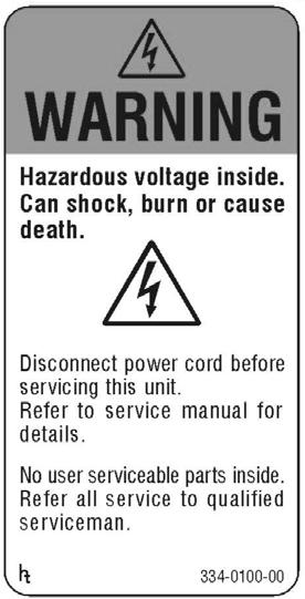
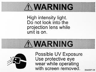
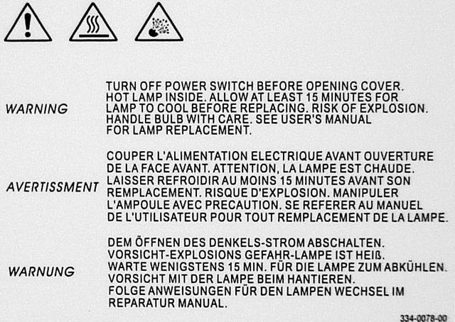
13 1.2 Your Safety and Margay s Safety The fully assembled display weighs about 68 lbs (30.8 kg). When assembling a wall, you will need two people to handle the Margay. WARNING The lamp needs very high voltages to start, around 15,000 volts. WARNING The lamp gets very hot. Allow it to cool before removing it. WARNING The lamp produces lots of light and UV radiation (ultra-violet) as well. UV light can damage your retinas. After the light leaves the lamp and passes through the DLP optical engine, there is no significant UV, although the light will be very bright. that is not available, wrap the electronics module in aluminum foil. Lamp(s) inside this product contain mercury. This product may contain other electronic waste that can be hazardous if not disposed of properly. Recycle or dispose in accordance with local, state, or federal Laws. For more information, contact the Electronic Industries Alliance at For lamp specific disposal information, check WARNING There is no electrical interlock on the screen. Opening the screen does not turn off the high voltage to the lamps. s Opening the rear cover does turn off the high voltage to the lamp. However, the lamp will still be very hot.. The plug on the power cord serves as the disconnect for this product. No user serviceable parts inside. All parts replacement is done at the module level by a qualified service technician. CAUTION There are no user serviceable parts inside. Refer all repair and maintenance to a qualified service technician.. Static electricity can damage sensitive electronic components. Always use a grounding strap with handling the electronics module or the optical engine if there are exposed components. When shipping these parts, do not use styrofoam peanuts. These carry static electricity and can damage the parts. Use an anti-static bag, or, if 4
14 5
15 English Disposal of old Electrical & Electronic Equipment (Applicable throughout the European Union and other European countries with separate collection programs) This symbol found on your product or on its packaging, indicates that this product should not be treated as household waste when you wish to dispose of it. Instead, it should be handed over to an applicable collection point for the recycling of electrical and electronic equipment. By ensuring this product is disposed of correctly, you will help prevent potential negative consequences to the environment and human health, which could otherwise be caused by inappropriate disposal of this product. The recycling of materials will help to conserve natural resources. Français Mise au rebut des équipements électriques et électroniques usagés (Valable dans l ensemble de l Union Européenne ainsi que dans les pays européens disposant de programmes distincts de collecte des déchets) Ce symbole appliqué sur votre produit ou sur son emballage indique que ce produit ne doit pas être traité comme un déchet ménager lorsque vous voulez le mettre au rebut. Il doit au contraire être remis à un site de collecte agréé pour le recyclage des équipements électriques et électroniques. En veillant à ce que ce produit soit mis au rebut de façon adéquate, vous contribuerez à prévenir les conséquences potentiellement négatives sur l environnement et sur la santé humaine qui risqueraient de se produire en cas de mise au rebut inappropriée de ce produit. Le recyclage des matériaux contribuera également à économiser les ressources naturelles. Deutsch Entsorgung von elektrischen & elektronischen Altgeräten (geltend für die europäische Gemeinschaft und andere europäische Länder mit separaten Sammelprogrammen) Dieses Symbol, zu finden auf Ihrem Produkt oder dessen Verpackung, macht Sie darauf aufmerksam, dass dieses Produkt bei der Entsorgung nicht als Hausmüll behandelt werden darf. Statt dessen sollte es an eine Sammelstelle zum Recycling von elektrischen und elektronischen Altgeräten gegeben werden. Helfen Sie mit, potenziell schädliche Einflüsse auf Umwelt und Gesundheit, die durch eine unsachgemäße Entsorgung dieses Produktes entstehen können, zu vermeiden und entsorgen Sie dieses Produkt ordnungsgemäß. Recycling hilft, natürliche Rohstoffe einzusparen. This symbol is only valid in the European Union. If you wish to discard this product, please contact your local authorities or dealer and ask for the correct method of disposal. Ce symbole n est valable que dans l Union Européenne. Si vous souhaitez mettre ce produit au rebut, veuillez prendre contact avec les autorités locales ou avec votre revendeur et renseignez-vous sur la méthode de mise au rebut correcte. Dieses Symbol ist nur innerhalb der europäischen Gemeinschaft gültig. Wenn Sie dieses Produkt entsorgen möchten, wenden Sie sich bitte an Ihre örtliche Behörde und fragen Sie nach der ordnungsgemäßen Entsorgungsmethode. Español Deshecho de equipos eléctricos y electrónicos (aplicable a la Unión Europea y a otros países europeos con programas de reciclaje independientes) La presencia de este símbolo en el propio producto o en su material de embalaje, indica que no se debe tratar como residuo doméstico cuando desee deshacerse de él. En su lugar, debe entregarlo en el punto limpio correspondiente de reciclaje de equipos eléctricos y electrónicos. Asegurándose de que este producto se desecha de forma correcta, ayudará a evitar posibles consecuencias negativas para la conservación del medioambiente y la salud humana, consecuencias que podrían darse si se deshace del producto de forma inadecuada. El reciclado de materiales ayuda a conservar los recursos naturales. Italiano Smaltimento delle attrezzature elettriche ed elettroniche usate (applicabile in tutta la Comunità Europea ed altri Paesi Europei che applicano programmi di raccolta differenziata) Il simbolo trovato sul prodotto, o sulla sua confezione, indica che il prodotto non può essere trattato come i domestici quando è il momento di smaltirlo. Al contrario, deve essere consegnato ad un centro di raccolta specializzato nel riciclaggio di attrezzature elettriche ed elettroniche. Assicurando che il corretto smaltimento di questo prodotto, si aiuterà a prevenire potenziali conseguenze negative sull ambiente e sulla salute umana, che possono essere provocate da uno scorretto smaltimento di questa attrezzatura. I materiali riciclati aiuteranno a conservare le risorse naturali. Nederlands Verwijderen van oude elektrische en elektronische apparatuur (toepasselijk in de volledige Europese Unie en andere Europese landen met afzonderlijke programma s voor afvalverzameling) Dit symbool dat op het product of zijn verpakking is aangebracht, geeft aan dat dit product niet mag worden behandeld als huishoudelijk afval als u het wilt wegwerpen. U moet het afgeven bij een specifiek verzamelpunt voor de recyclage van elektrische en elektronische apparatuur. Door te garanderen dat u dit product op de correcte manier wegwerpt, helpt u potentiële negatieve gevolgen voor het milieu en de menselijke gezondheid, die zouden kunnen worden veroorzaakt door een onrechtmatig wegwerpen van het product, te voorkomen. De recyclage van materialen helpt het behoud van natuurlijke bronnen. Este símbolo solamente es válido en la Unión Europea. Si desea deshacerse de este producto, póngase en contacto con las autoridades locales o con su distribuidor y pida información sobre el método de disposición adecuado. Questo simbolo è valido solo nell Unione Europea. Per smaltire questo prodotto, mettersi in contatto con le autorità locali o con il rivenditore e chiedere informazioni sul corretto metodo di smaltimento. Dit symbool is alleen geldig in de Europese Unie. Als u dit product wenst weg te gooien, dient u contact op te nemen met uw lokale instanties voor details over de gepaste methode voor afvalverwijdering.
16 Português Eliminação de equipamentos eléctricos e electrónicos usados (aplicável na União Europeia e noutros países europeus com programas próprios de recolha destes equipamentos) Este símbolo, colocado no produto ou na respectiva embalagem, indica que o produto não deve ser tratado como lixo doméstico aquando da sua eliminação. Em vez disso, deve ser entregue num ponto de recolha de equipamentos eléctricos e electrónicos para posterior reciclagem. Ao garantir a correcta eliminação deste produto, estará a evitar consequências potencialmente negativas tanto para o ambiente como para a saúde humana. A reciclagem de materiais ajuda a preservar os recursos naturais. Usuwanie zużytego sprzętu elektrycznego i elektronicznego (Dotyczy krajów Unii Europejskiej i innych krajów europejskich z oddzielnymi programami zbiórki odpadów) Polski Obecność tego symbolu na produkcie lub na opakowaniu z produktem oznacza, że tego produktu nie można wyrzucać razem z odpadkami domowymi. Należy go przekazać do punktu zbiórki w celu poddania recyklingowi podzespołów elektrycznych i elektronicznych. Usunięcie tego produktu w prawidłowy sposób, pomoże w zabezpieczeniu przed negatywnym wpływem odpadów na środowisko i zdrowie ludzi, powodowanym przez niewłaściwe usuwanie produktu. Przetwarzanie materiałów pomaga w zachowaniu zasobów naturalnych. Este símbolo apenas é válido na União Europeia. Se quiser eliminar este produto, contacte as entidades locais ou o seu fornecedor para ficar a saber qual o método de eliminação correcto. Ten symbol obowiązuje wyłącznie w krajach Unii Europejskiej. Informacje dotyczące prawidłowej metody usunięcia tego produktu, można uzyskać u władz lokalnych lub u dostawcy. Avfall av förbrukad elektrisk och elektronisk utrustning (Tillämpbart i hela Europeiska unionen och andra europeiska länder med separata samlingsprogram) Svenska Den här symbolen som finns på din product eller på dess förpackning påvisar att produkten inte ska behandlas som hushållsavfall när du vill slänga bort den. Istället ska den lämnas över till en lämplig uppsamlingspunkt för återvinning av elektriska och elektroniska utrustningar. Genom att tillförsäkra att den här produkten återvinns på ett riktigt sätt hjälper du till med att förhindra möjliga negative konsekvenser för miljön och mänsklig hälsa. Det kan annars orsakas på grund av olämplig sophantering av den här produkten. Återvinning av material kommer att hjälpa till att bevara naturtillgångar. Suomi Vanhojen sähkö- ja elektroniikkalaitteiden hävittäminen (Soveltuva kaikkialla Euroopan unionin alueella, sekä muissa Euroopan maissa, joilla on erilliset keräysohjelmat) Jos tuotteessa tai sen pakkauksessa on tämä symboli, sitä ei pidä hävitettäessä käsitellä tavallisena kotitalousjätteenä, vaan se kuuluu toimittaa sähkö- ja elektroniikkalaitteiden kierrätyspisteeseen. Varmistamalla, että tämä tuote hävitetään asiaankuuluvalla tavalla autat estämään mahdollisia ympäristölle ja ihmisille koituvia negatiivisia seuraamuksia, joita sen vääränlainen hävittäminen voi aiheuttaa. Materiaalien kierrättäminen auttaa säilyttämään luonnonvaroja. Den här symbolen är endast giltig inom den Europeiska unionen. Om du vill slänga bort den här produkten ska du kontakta lokala myndigheter eller återförsäljar, och fråga efter lämplig avfallsmetod. Tämä symboli on voimassa ainoastaan Euroopan unionin alueella. Jos haluat hävittää tämän tuotteen, ota yhteyttä paikallisiin viranomaisiin tai jälleenmyyjään ja tiedustele asiaankuuluvia hävittämistoimenpiteitä.
17 6
18 2 Installing 2.1 What You Will Do Installing the VIM (Video Input Module) Installing the Big Picture Key Building the Wall, First Row Building the Wall, Second Row and Up Building a Banner, Upside Down Connections Connections, Analog & Digital Sources Connections, Video Sources Connections, Power Connections, Control: RS232 & RS Installing and Removing Screens Installing the Screens Opening or Removing a Screen Opening a Screen Temporarily for Work 36 7
19 2.1 What You Will Do The series of steps here give only a basic outline of the installation process. See the specific sections for details (page numbers in parentheses). Installation 1. Unpack the Margays. Leave the screens in their containers. You won t need the screens for a while. 2. If it was purchased, install the VIM (Video Input Module) in each Margay. (10) 3. If it was purchased, install the Big Picture key in each Margay. (12) 4. Build the wall of Margays, leaving the screens off. (14) 5. Connect the Margays to power (26), picture source (22 & 24) and communication. (28) 6. Install the screens, starting with the bottom row. (32) Configuration 1. Align each optical engine to the screen. (38) 2. Adjust Margay to each of the inputs you will use: analog computer (44), digital (48), video (50). 3. Color balance the wall. (52) 4. Set up Big Picture, if you are using it. (54) 5. Save your work. (62) 8
20 9
 in the Margay s electronics module. (The electronics module is the part the receives all the input and output cables.")

21 2.2 Installing the VIM (Video Input Module) It is easier to install the VIM board in Margays before they get stacked in a wall. The Video Input Module option is installed in the field. You will install the VIM (Video Input Module) in the Margay s electronics module. (The electronics module is the part the receives all the input and output cables.) If the electronics module is installed in the Margay, you will remove it partially. 4. Pull the module up and partly out. a. It may take a bit of maneuvering to get the connectors at the bottom to come up with the module. b. Do this carefully so you do not damage the connectors. All connectors are latched in place. They aren t particularly delicate, but they won t stand very rough treatment. 1. Turn off the AC power to the Margay and remove the power cord. 2. Open the door on the right side of Margay (as viewed from the front) exposing the electronics module. 5. Install the VIM in the electronics module. 3. Loosen the two screws at the top of the electronics module. 10

22 6. Put in the four screws. Be sure the VIM is pressed well into the socket. One of 4 screws. 7. Put the electronics module back in place and secure it with the two screws. 8. Reconnect power, if you removed it earlier. 11


23 2.3 Installing the Big Picture Key Planar s Big Picture key allows a wall of Margays to spread one picture over the entire wall. The Big Picture key is installed in the field. You can install the Big Picture key without removing the electronics module. 3. Plug the BP key into its socket. 1. Open the door to the electronics module. CAUTION Be sure all six pins go in the socket holes. If the key is installed incorrectly, the entire electronics module may not function at all. 2. Remove the cover of the Big Picture key socket. 4. Replace the BP key cover. The Big Picture key can be installed while the Margay has power. However, the key will not take effect (Big Picture will not work) until power is cycled on again. 12
24 13
25 2.4 Building the Wall, First Row It is most important to make the first row straight. Do not put the screens on yet. Laying the first row 1. Set the first row of Margays side by side without the screens. Bolt them loosely together near the bottom with the long side-to-side bolts, washers and wingnuts. 2. Attach the screen supports to the front edge of the first row. The screen support only mounts one way and is used on the bottom row only. It provides a stop or rest for the bottom screens. 3. Check the straightness of this row. This first row must be absolutely straight. Do not use your eye alone to judge straightness. Use a tightly stretched string or a very long level. It is ok if the row is not level, as would be the case in a tilted wall, but it must be straight. 4. Use shims under the Margays to make the row straight vertically. 5. When the row is straight, tighten the bolts holding them together. Then check straightness one more time. 6. Go to next section (page 16). Why is straight so important? All Planar displays that stack must have a straight first row. If the first row is not straight, the arrangement gets worse as the wall goes up, and the screens won t align properly. Margay is a little more critical of straightness, because its screens have almost no mullions. The mullion is the outside border of the screen. In most Planar products this is a narrow edge of metal that holds the screen in place. In Margay the mullion is a thin piece of tape. The advantage of this mullion-less screen is that the finished wall will have almost no black lines between images on the screens. 14


26 Using string to see that the row is straight First row with screen supports in place Screen support bolt, two at each end Side-to-side bolt with wing nut at bottom of neighbor Margays 15


27 2.4 Building the Wall, First Row Building the Wall, Second Row and Up If the first row is straight and solid, the rest of the rows will be easier. Continuing to build the wall 1. Stack another row of Margays on the first row. As you stack, be careful with the pins that align the rows. 3. Then bolt the Margays top-to-bottom through the top-to-bottom hole using the Vertical bolts, ¼" As each Margay is placed in the second row, secure it to the lower unit with two Front screws. 4. Bolt this row side-to-side as you did the first row. This time the bolts will go through four Margays, two in the first row, two in the second rows. The 16


28 end of the row has shorter side-to-side bolts to secure just two Margays together. CAUTION For high walls, over 2 units high, and for all tilted walls, see the safety instruction below. Safety with high or tilted walls Because the Margay is so narrow front to back, there is a danger of tipping with high walls. Margay has tie-back points on the rear to prevent this. Use these tie-backs to secure the Margay wall to a structural part of the building. Don t wait until the wall is finished. Do this as you build the wall up. If the wall is tilted forward, tie the Margay all the way up. 5. Check straightness of this second row. The tie-back points are ¼ x20 threaded holes. 6. Continue in this way with the rest of the rows, checking straightness as you go. Make sure the fronts of the units are flush with each other. This will make screen alignment easier. 17
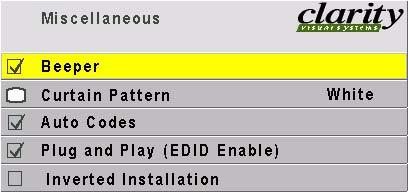
29 2.4 Building the Wall, First Row Building a Banner, Upside Down It is possible to hang a single row of Margays upside down to make a banner. Be sure the ceiling can hold them. Planar does not provide any special brackets to hang a Margay upside down. There are too many variables to consider, so the method to use is best determined on site. Whatever you use to attach Margays overhead, it must be capable of sustaining five (5) times the weight of a Margay, which is 68 lbs or 30.8 kg. The mounting system must therefore hold 340 lbs or 154 kg for each Margay. You may use the screen supports to cover part of the Margay, but they are not necessary in the upside down configuration. Inverting the picture and menus In the Miscellaneous menu (under Advanced Options) check Inverted Installation. This one check mark inverts the picture and the menus. It also reverses the left-right of the optical engine alignment motors so left and right will be correct for you. MENU > ADVANCED OPTIONS > MISCELLANEOUS Screens when inverted The screen supports, which normally hold screens up, will now be above the row of screens. You may wish to devise some way to push the screens up from the bottom to press them against this support to prevent a gap. It is not necessary, of course, to use the screen support parts in an inverted installation. 18
30 . 19
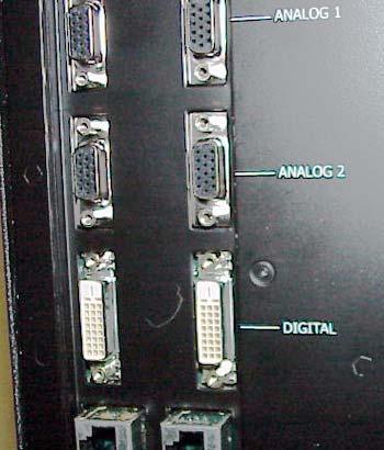
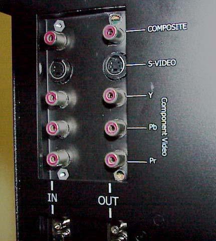
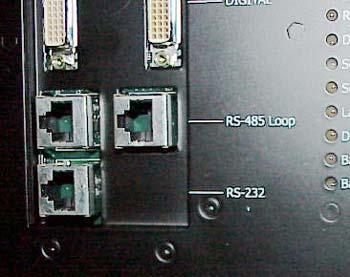
31 2.5 Connections Margay has four groups of connectors. All inputs are paired with loop-thru outputs (except RS232 In). The inputs are toward the rear of the Margay. Analog and digital connectors Two analog connectors and one digital (DVI) connector have their separate loop-thru outputs. The Analog outputs (buffered) always carry the corresponding analog input picture. The digital output is different. The digital output carries a digitized version of the selected input. If you change the active input in the Picture menu, the digital output changes. See Connections, Analog & Digital Sources on page 22. Video connectors Video connections are optional. The Video Input Module (VIM) is not installed at the factory; it is installed in the field by the installer. When installed, the VIM accepts composite, S-video and component video (YPbPr). Each input connector is paired with its separate loop-thru output. See Connections, Video Sources on page cubes when using 230V. 115 VAC No more than See Connections, Power on page 26. Control connectors You can control the Margay with a remote control or with serial commands from a computer or other device. Send commands in either the RS232 or RS485 standard. Normally, you send RS232 commands to one Margay s RS232 In and loop out the RS485 Out to the next cube s RS485 In. RS485 has better long-distance communication. See Connections, Control: RS232 & RS485 on page 28. Power AC power (115V or 230V) can be looped thru to neighboring cubes. The limit on loop-thru is 4 Margays when using 115V; 8 Margays when using 230V. The power supply is auto-ranging. 20


32 Electronics module as seen from the front. The electronics module door is open. 21
33 2.5 Connections Connections, Analog & Digital Sources The Digital Out connector carries the selected input. All of the source inputs, the picture inputs, have loop-thru output connectors. These loop-thrus are buffered. Analog 1 and Analog 2 are 15-pin VGA-type connectors. Margay will accept a wide range of computer resolutions up to and Each of these connectors has a dedicated loop-thru output. These connectors are also used for RGB video with separate H&V sync, composite sync, or sync on green; also for YPbPr video at 480p, 720p, or 1080i. When an Analog input has a source with sync on green or composite sync, the DVI Out may not show the picture properly. If the source is present at power up, it usually works well, but if you disconnect and reconnect the source, the DVI loop-thru stops working for these two types of sync. Digital In is a standard DVI cable. It has a loopthru, but this Digital Out connector is not dedicated to the Digital In connector. Instead, the Digital Out connector carries the picture of the currently selected input. For instance, if the Analog 1 connector is selected, the picture on the Digital Out connector is a DVI version of that Analog 1 picture. The DVI does not carry the picture from the composite, the S-Video, or the component YPbPr inputs. Limits of loop-thru No signal can loop-thru forever. There is always some degradation of the signal along the way. If you want to loop a single source to a number of Margays, try one of the methods shown here. In diagram A the signal loops thru six times at most. In diagram B the signal loops thru four times at most. In each diagram the cubes marked X is the farthest from the source. SVGA PC A Connecting with a combination of analog and digital loop-thru SVGA PC B Connecting with a distribution amplifier and loop-thru Distribution Amplifier Analog connections X X Digital connections X Digital connections Digital connections X 22
34 In Out 23
 on page 10) Composite video Connect an NTSC, PAL, or SECAM composite source to COMPOSITE IN. Loop-thru from COMPOSITE OUT.")
35 2.5 Connections Connections, Video Sources Video is a option installed in the field. If you did not install the optional Video Input Module (VIM), skip this section. (2.2 Installing the VIM (Video Input Module) on page 10) Composite video Connect an NTSC, PAL, or SECAM composite source to COMPOSITE IN. Loop-thru from COMPOSITE OUT. S-video Connect an NTSC or PAL S-video source to the 4-pin DIN connector, S-VIDEO IN. Component video NTSC or PAL rate interlaced video can be fed into the Y, Pb, and Pr IN connectors and looped out. Be sure the DVD player is not set to progressive scan. Use the Analog 1 or 2 connector for progressively scanned DVD. When you choose Component Video in the Picture menu, the Colorspace automatically switches to YPbPr. When you choose another picture source, Colorspace switches back to RGB. The Analog inputs have a greater range of modes for component than the YPbPr video inputs. If your YPbPr source does not work in the video inputs, try Analog 1 or 2. Component video YPbPr sources can also be fed into the Analog 1 or Analog 2 inputs. Colorspace must be manually changed to YPbPr in this case. Use RGB when the analog source is normal RGB. Use YPbPr when the source is component analog. 24
36 25
37 2.5 Connections Connections, Power AC loop-thru means you won t need as many mains sockets. Bring in AC power next to the electronics module. The voltage can be 115 (90V 132V) or 230 (200V 254V). Loop the AC power out to the next Margay, if you wish, but limit this to four (4) connected Margays for 115V operation and eight (8) connected Margays for 230V operation. WARNING Do not exceed the recommended number of Margays linked in series for AC power or the current draw will be too great. The AC switch on each Margay controls that cube only. Turning off the switch in the first cube does not cut the AC power to the remaining cubes. The switch is lit when it is ON and there is AC power to the Margay. The AC input is fused with a 10A fuse. If for some reason the fuse in any Margay blows, all the cubes downstream from this one will go off. 26
38 AC power in and out No more than VAC 27
39 2.5 Connections Connections, Control: RS232 & RS485 With serial control, you can control a whole wall, several walls, and any single display in them. Connect to the computer Connect the first cube in the wall to the serial out port of a computer or another type of controller, such as a video controller. Connect with computer serial cable, such as Cat-5, using straight-thru cable. You will probably need to convert the 9-pin serial port to RJ45 with an adapter, which you can buy in most electronic stores. For very long runs of RS485 cable, it may be necessary to terminate in the last Margay in the string. See 4.4 Controlling Margay with RS232/RS485 on page 74. Wiring the adapter To go from 9-pin D-sub serial connector on the back of the ccomputer to an RJ45 connector, use a standard RJ45-to-9-pin adapter. Wire it internally as shown. The wiring shown for this adapter is correct for straight-thru cables. Straight-thru cables are wired 1-to-1, 2-to-2, etc. Yellow wire pin 3 Black wire pin 2 Green wire pin 5 RJ45 9-pin female 9-pin Connect from the computer or controller to the first Margay. It doesn t matter which cube this is. Connect this first cube s RS485 Out to the next cube s RS485 In. Start with RS232 and loop all the rest with RS485. Information about controlling with RS232 is in 4.4 Controlling Margay with RS232/RS485 on page 74. For best results, the RS485 cables should be twisted pair. The pairs are pins 3 & 6 (signal) and pins 1 & 2 (ground). CAT5 cable has the correct twisted pairs. 28
40 29
41 2.6 Installing and Removing Screens The Margay screens in a wall are quite close together, so the order in which you remove them from a wall is very important. WARNING Do not install or remove any screen until you have read and understand this section. If screens are installed or removed improperly, they may be damaged. The next two sections describe in detail how to install and remove screens properly Installing the Screens on page Opening or Removing a Screen on page 34 About no-mullion screens One of the best features of Margay is its zero mullion screens. The screens are as close together as possible, which means there is very little dead space between them. The Margay screens float. When they are installed, they will move up, down, right and left a little. This floating allows them to be position as close to each other as possible. Screens next to each other touch each other. Floating also means that screens higher in a wall are resting on the lower screens. The screens in the bottom row rest on screen supports, the skirt at the bottom that holds all the screens up. The screens won t fall off if the screen support is removed or if screen in the bottom row is removed. However, they may move down a little. Avoiding damage to the screens The close, zero mullion screen arrangement comes at a price: You have to be more careful when installing and removing screens than with other Planar products. WARNING Pulling the screens off incorrectly can damage the screens. See the example on the facing page. Avoiding gaps between screens When you install screens in a wall, it is important to put them on in the proper order. 30
42 View from above a row of Margays When Margays are installed in a row, the screens are very close together. Top of Margay 1 Top of Margay 2 Top of Margay 3 Screen 1 Screen 2 Screen 3 Pulling a screen from the outside of the row causes it to bind with its neighbor. Top of Margay 1 Top of Margay 2 Top of Margay 3 Screen 1 Screen 2 Pulling a screen from the outside edge. DON'T DO THIS! ouch Screen 3 The proper way is to make the first pull on the neighboring edge of an outside row. Top of Margay 1 Top of Margay 2 Top of Margay 3 Screen 1 Screen 2 Screen 3 Pull the inside edge of the column first, but just a little. Top of Margay 1 Top of Margay 2 Top of Margay 3 Then pull the outer edge to release all the spring latches. Screen 1 Screen 2 Screen 3 Then pull the outer edge. 31


43 2.6 Installing and Removing Screens Installing the Screens Start in the middle of the bottom row and work outward and upward. First 1. Be sure the wall of Margays is straight and the corners are square. Measure the diagonals of the whole wall. If the diagonals are equal, the wall is a perfect rectangle. 2. The screen supports should be installed on the bottom row of Margays. Screen supports Then 3. Start in the middle of the bottom row and install that screen. a. Pull the screen rails all the way out on both sides of the Margay chassis. c. With one person holding each side of the screen, hang the screen on the rail so the pin goes into the slot. 4. Slide the screen closed, lifting it slightly so the screen won t scrape on the screen support below. Next 5. Install the screens to the left and right of the center to complete the bottom row. a. After you add a screen, press it toward the center. 6. Install the screens above the center screen. a. Left each screen and you press it in so it doesn t scrape on the screen below. b. Continue until you reach the top. 7. Check the line of this bottom row of screens. If they are not straight, use shims on the top of the screen support until the screens are straight. 8. Complete the second row, working outward and pressing the screens inward after they are pressed home. 9. Working upward and outward, finish all the rows. Final adjustment Check all the screens for alignment with each other. The lines between screens should form straight lines where they intersect. b. The screen rails have a large pin and the screens have an L-shaped slot. The four corners should meet like this not like this. 32
44 In a wall of Margays, install the screens starting with the center of the bottom row and work out to the ends. Then install the screens above the middle until you have an inverted T. Finally, install the rest of the rows, complete each row before moving up. 33
45 2.6 Installing and Removing Screens Opening or Removing a Screen Removing a screen from a single Margay standing alone is not a problem. Simply grasp the sides of the screen and pull forward sharply. The spring latches will pop loose. Removing a screen from a Margay in a wall is more exacting, because the screens are so close together. On the opposite page, look at the row of Margays. To remove a screen on the outside column in a wall, do not start at the outside edge. This seems the logical place to start, but it will cause the outside screen to crunch against the next screen to the center. Notice also that if you want to remove a screen in the middle of a wall, you should work from the outside of the wall inward. Hints When pulling with the suction cup, always pull at a slightly up angle. This keeps the screen from scraping the screen below. Place the suction cup puller near the corner of the screen. Start at the outside and work in. 4. You will hear the screen latch click and release. Pulling up a little keeps this screen from rubbing the screen below. Release the latch at top and bottom of one side. CAUTION When you pull the edges out, pull out only ½" (2 cm). That is enough to release the spring latches without harming the next screen. 4 Then pull this edge. 3 Place suction cup at these points Never pull the open edge first. Steps to remove a single screen from a Margay wall With both edges free, remove this screen completely Suppose you want to remove this screen Start with this screen and pull this edge. 1 2 Next, pull this edge Place the suction cup near the corner of the screen and pull slightly up and outward sharply. 34
46 7. 4 Then this edge Now here Then this edge Finally, pull this edge. 2 1 This may seem like a long way to pull a single screen, but this order of operations helps prevent screen damage. 35


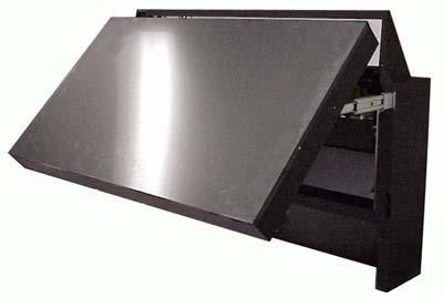
47 2.6 Installing and Removing Screens Opening a Screen Temporarily for Work The Margay screen props open for work from the front. 1. Carefully open the screen of the Margay you want to work on. See Opening or Removing a Screen on page Pull the screen all the way out. 3. Use the hook to hold the screen at an angle. 4. Be sure to close the hook along the slider before closing the screen. 36
48 3 Aligning and Adjusting 3.1 Adjusting Margay s Engine: Important Step Adjusting Each Margay To Its Source Adjusting to Computers, Analog RGB Adjusting Input Levels Manually Adjusting to Computer Sources, Digital Adjusting to Video Sources Color Balancing a Wall of Margays Spreading One Picture Over a Wall Scaling and Cropping Zoom and Position Viewport Adjustment Saving Your Work & Recalling a Memory Memory: What Is Saved? And Where? 64 37

49 3.1 Adjusting Margay s Engine: Important Step The optical engine must be adjusted to aim the picture accurately at the screen. Although the optical engine was perfectly adjusted when the Margay left the factory, vibration along the way may have moved it. CAUTION It is important to check this mechanical adjustment of the optical engine before any electronic adjustments are made to the picture. Aligning the optical engine 1. Open the Engine Alignment menu. 2. In the last item in the menu, choose Grid. This pattern shows all the pixels in the optical engine. 3. Start by positioning the grid pattern to the center of the screen. a. The Left and Right Side controls move the left and right sides of the grid up and down. These two controls react with one another a little, so moving the right side may affect the left side, too. b. Separately the Left and Right Side controls adjust rotation of the grid image. Together they adjust the vertical position. c. Use the Horizontal control to move the grid image left and right. Again, this control interacts somewhat with the up and down controls of left and right. 4. When the grid image is centered, use the Image Size control to size the image. Try to lose (hide) one pixel at the edge of the screen. a. The other pattern, Alignment Dashes can help you here. This pattern shows the last six pixels at each edge. b. To hide one pixel, adjust the size so that you see five dashes at each edge. c. There may be a small amount of curvature (barrel or pincushion distortion) at the edges. This is normal. You will have no more than about one pixel of curvature along any edge. d. The Image Size control may affect the rotation or position of the image, so go back and forth between the controls to find the best adjustment. What if you CAN T move the image enough? In some rare situations, you may not be able to use the Engine Alignment menu to move the image far enough on the screen. If so, you must manually move the optical engine carriage. 1. If you have moved the image using the Engine Alignment menu, move the image back to the center. You can find the center of the range of alignments by finding each extreme and moving the image to the middle. By centering the alignment engine you will retain fine image adjustment settings. In the following steps, you will do gross adjustments to move the image. You must still do fine tuning of the image alignment using the Engine Alignment menu. 2. Remove the rear panel (6 ¼-turn screws). 3. The optical engine carriage is exposed. (Cables normally attached to the optical engine have been removed for these pictures.) Hiding one pixel at all sides is ideal. Try to make it at least one pixel and no more than three. 38
50 4. Loosen the two mounting nuts on the left side of the carriage. 8. To move the screen image up or down tighten or loosen the adjustment screws on the both sides of carriage. Loosen these two nuts 5. Loosen the single mounting nut on the right side of the carriage Move image up or down by adjusting this screw... Loosen this nut 6. To move the screen image to the right, move the carriage to its left (as you face the carriage from the back of the unit). 7. To move the screen image to the left, move the carriage to its right.... and this screw a. To move the screen image down, tighten these screws (turn the screws clockwise). b. To move the screen image up, loosen the screws (turn the screws counter-clockwise). These adjustments are for large physical movement. You ll still need to do fine tuning of the picture position using the process described in Aligning the optical engine on page After you have moved the image to a more reasonable position, tighten the three mounting nuts you loosened earlier. 10. Now fine-tune the image position as described in Aligning the optical engine on page
51 40
52 Alignment Dashes Use the Alignment Dashes pattern to show how many pixels are visible at each edge. Use the Grid pattern to adjust rotation and to align all patterns in a wall. 41
53 3.2 Adjusting Each Margay To Its Source 3.2 Adjusting Each Margay To Its Source The source picture from computer, video, DVD is not always perfect in its size or strength; it does not always conform exactly to a standard. Margay has a way to compensate for this. Computer sources vary quite a bit from computer to computer. They even vary between video outputs on the same video card. Video sources vary more. To make the Margay respond correctly to these non-standard sources we adjust Input Levels. Input Levels for computer sources, analog, see page 44 Input Levels for computer sources, digital, see page 48 Input Levels for video sources, page 50 How does Input Level relate to Color Balance To make all the displays show the same color and brightness across the whole wall, you need to adjust input levels and do color balancing. You can do Input Levels first, or you can do Color Balance first. It doesn t matter. But they must both be done. Displays differ from one another because of very small differences in the color of the light produced by the lamp and by differences in the dyes used to make the color in a DLP optical engine. In color balancing you use the display s internal test patterns of white, first, then gray. The internal pattern assures that a pure white is used. Selecting the source 1. Press MENU on the remote. 2. Select PICTURE and press ENTER. 3. Select SOURCE and press the left ARROW key. 4. Choose the source you want and press ENTER. 5. Press MENU again to close all menus. Input Levels and Color Balance do not affect each other, but they both affect the final picture. Color Balancing the displays, page 52 What does Input Level do? For analog computer sources adjusting to the computer s picture output means finding what that computer means by black and white. Black is supposed to be a voltage of zero coming from the computer s video card, but it almost never is. White is supposed to be a voltage of 0.7 volts, but it usually isn t either. The Input Level adjustment process asks you to provide a picture from the computer that is black, then one that is pure white. With these, you can quickly and automatically make the display learn what this computer means by black and white. The result? Good pictures, using all the dynamic range of color coming from the computer. For Input Levels, you must use black and white coming from the computer you will use for the program. You don t make this adjustment with your work laptop and then switch to another computer for the display s program of pictures. What does Color Balance do? Color balancing adjusts all the displays in a wall so they produce the same colors across the entire wall. 42
54 43
55 3.2 Adjusting Each Margay To Its Source Adjusting to Computers, Analog RGB Adjusting to Computers, Analog RGB The best way to adjust levels is the semi-automatic method. Adjusting levels semi-automatically This is quick and easy if you can get a black picture and a white picture from the source computer. 1. Display a black picture from the source. This must come from the computer source that will be used for the program. It does no good to use your laptop for this adjustment, then connect to a different computer for the program. Nor can you use the Margay s black test pattern. (Hint: Make a black screen from Windows Paint program.) 2. In the MANUAL LEVELS menu, select Auto Black Level and press ENTER. (There are several paths to the Manual Levels menu as shown in the pictures.) 3. Display a white picture from the source. 4. Select AUTO WHITE LEVEL and press ENTER. That s all there is to it. The Margay is now adjusted to the black and white levels of this computer using this video card. If you change computers or video output cards in the computer, you must do this again. Adjusting levels completely automatically Open the AUTO SETUP OPTIONS menu and check DO BLACK/WHITE LEVELS. You can check the other items, too, particularly FREQUENCY and PHASE. Now press SETUP. Margay looks for the darkest pixel and the brightest pixel in the picture and adjusts itself so that these are the truly the darkest and brightest. When the Black/White Levels item is checked, the Margay will do this automatic level adjustment whenever a completely new source is displayed. When a saved memory is recalled from the Recall menu, Margay does not do any auto setup. Which is best: Manual, Semi-Auto, or Auto The manual and semi-automatic methods are more accurate. The automatic method is sometimes not accurate enough for the White Level. The good news is that you should only have to do the manual or semi-auto method once for each computer source. Save these settings in the Save menu, How to Save to a Memory on page 80. Then use Recall to instantly bring it all back. When to re-adjust levels You should re-adjust black and white levels whenever: the computer is changed; the video card in the computer is changed, or you switch the source for this cube to a different video card output in the same computer; you change the electronics module. Adjusting to computer sources manually See Adjusting Input Levels Manually on page 46. What is a completely new source? Margay remembers all the values in the last 10 pictures. If a new picture comes from a different source, such as from a different computer, and that picture has almost exactly the same resolution, number of active lines, number of blanking lines, etc., the Margay will assume that this is a source it has seen before and use the remembered setup values. This is a different sort of memory from the 40 numbered memories described in Using the Memories Efficiently on page 78. On the other hand, if the new source is sufficiently different, Margay will engage all the checked processes in the Auto Setup Options menu. 44
56 45
57 3.2 Adjusting Each Margay To Its Source Adjusting Input Levels Manually It is rarely necessary to adjust input levels manually. You can skip this section. Adjusting levels manually 1. Display an all-black picture from the source computer. 2. Press LEVEL on the remote. 3. Select MANUAL BLACK LEVEL and adjust it up and down with the +/ keys to make the three CENTER POINT values go to zero. If they do not all touch zero at the same time, use the individual colors under MANUAL BLACK LEVEL to adjust them. Do not go beyond the point where the Minimum just goes to zero. The idea is to just touch the zero level. 4. Display an all-white picture from the source computer. 5. Select MANUAL WHITE LEVEL and adjust the levels until the CENTER POINT values just touch 255, adjusting the individual colors as necessary. It is not a good idea to use the levels to make all the displays in a wall match each other. That should be done with the Color Balance menu. ( Color Balancing a Wall of Margays on page 52.) 46
58 47
59 3.2 Adjusting Each Margay To Its Source Adjusting to Computer Sources, Digital Digital sources do not normally need adjustment, but the controls are there if you need them. These controls are advance level controls and should not be adjusted unless you have been briefed by the factory or are familiar with black level adjustments. They are used to correct the digital blacks that come from video cards that have incorrect levels. Don t use these controls unless you have been briefed by Planar or you are familiar with black level adjustments. These controls are usually not necessary. 48

60 This form of the Input Levels menu appears when the current source is Digital and the colorspace is RGB. This form of the Input Levels menu appears when the current source is Digital and the colorspace is YPbPr. 49
61 3.2.3 Adjusting to Video Sources Video adjustments are quite a bit like the controls on a television receiver. Adjusting the picture 1. Select a video source in the Picture menu. When the VIM option is installed (Video Input Module) Margay has available a. one composite video, b. one S-Video, and c. one component (YPbPr) input. 2. Press LEVEL on the remote. 6. If the color bar pattern has a pluge, you can use it to adjust Brightness. These controls are also used for analog sources when you chose YPbPr Colorspace. Now you have two choices. Adjust using any picture from the video source. Adjust using a standard color bar pattern from the source. Pluge Adjusting with any picture This procedure must be done after you adjust color balance (page 52). 1. Choose pictures that have blacks and whites represented as well as a variety of colors. 2. Adjust Contrast, Brightness, Saturation and Hue on one Margay until it looks satisfactory. 3. Adjust all the other Margays in the wall so they have the same values for Contrast, Brightness, Saturation and Hue as the first Margay. Adjusting with color bars 1. If possible, use a color bar pattern from the video source you will use for the program material. You cannot use the color bar from the Test Patterns menu. 2. In the Picture menu, check Blue Only. You should see only the alternate color bars, all of them blue. 3. Adjust Saturation to make the outer two color bars match. Match them in brightness; they will already match in color. 4. Adjust Hue to make the inner two color bars match. 5. Uncheck Blue Only Adjust Brightness so you cannot see the different between these two marks, but you can see the difference between these two marks. When a video source is selected, Auto Setup Options is not available. Adjustments must be made manually. 50
62 Saturation Match these Match these Adjust Saturation so the outside bars match when Blue Only is checked. Hue Match these Match these Adjust Hue so the inside bars match when Blue Only is checked. 51
63 3.3 Color Balancing a Wall of Margays Color Balancing can be done before or after Input Levels. The object of color balancing is to make the individual units show the same colors. When we see a red car move across a video wall from one display to another, we want it to have the same color for the whole trip, not change from red to maroon to orange. The displays naturally have slightly different colors from one display to the next, because of slight variations in the lamp and DLP engine. This cannot be avoided, but we can compensate for it with color balancing. Color balancing is subjective. It may seem strange at first, but it gets easier with practice. Fortunately, you don't have to match all the colors; you only have to match whites and grays. When you make all the displays look the same with White and Gray, all the other colors will look the same. It is not necessary to achieve a perfect white or a perfectly colorless gray. It is only necessary that all the displays look alike when they display white and gray. CAUTION Never try to match the colors of the display units with the Black and White Level controls or with the Video Controls. You will not like the results if you do. Color Balancing 1. Turn on all the units in the wall and let them warm up for at least five minutes. The lamps must be thoroughly warm before you color balance. 2. For each display, press MISC once on the remote. 3. Set Gamma at the bottom of the menu to either Video or Film, but be sure this is the same for all cubes. 4. Set White Boost to Off. 5. Set Test Pattern to White. Always use the internal Test Patterns for color balancing, not an external pattern. If the wall has never been color balanced, make sure you start with the same color temperature setting on each cube. If you are not interested in achieving a specific color temperature, use the default of 8500K, which is the brightest. If the cube has been color balance before, it will display CUSTOM in its color temperature setting, because the balance values don t match any of the pre-set color temperatures. 6. Look at the Color Balance values on all displays. All the White balance values should be 100, and all the Gray balance values should be 7. If any values are not that way, select Reset to Defaults and press ENTER. This is where you should always start color balancing. 7. Select Hide Menu and press ENTER on each display. This will remove all the menus so you can see the whole screen on all displays. (To re-open the Color Balance menu, press ENTER for that displays.) 8. Look at all the displays together. Stand far enough away from the wall so you are looking almost squarely at all of them. Pay attention to the large central area, not the edges. 9. Find the darkest display. This is the baseline display. Do not change this one. 52
64 10. Pick a display next to the baseline display, above, below, or to the side. This will be the variable display. Turn on the Color Balance menu for this variable display by pressing ENTER. Be close to the display to do this so only this one display has the Color Balance menu showing. 11. Match the brightness of this variable display to the baseline display. Match brightness first. Move the selector arrow to White Balance All. With the left key, reduce the brightness until it matches the baseline display. Select the individual colors and adjust the amounts of Red, Green and Blue to achieve the best match in color and brightness to the baseline display. 12. When the first variable unit matches the baseline unit, it becomes another baseline unit. Turn off its Color Balance menu with Hide Menu. 13. Choose another variable unit next to any baseline display, turn on its Color Balance menu, and match its white to any baseline display. 14. When all displays match in white, change Test Pattern to Gray so all the displays show an internal gray pattern. 15. The gray values range from 0 to 15, and they are all now set at 7. Therefore, gray can be adjusted up and down. Choose a display that has a middle brightness and that has very little color in gray. This becomes the first baseline display for gray. It does not have to be the same as the baseline unit used for White. 16. Proceed as before, matching the grays one display at a time. Always work with adjacent displays. 17. When all displays match in gray, turn off the test pattern on each display. Color Balance values are saved for all input sources in the same memory location. Color Balance is the same for all sources. Bright Changes in the White value moves this end point. Output brightness Dark Output brightness Black Changes in the White values affect the Gray values. Changes in the Gray value move this mid point. Input Signal Changes in the Gray values do not affect the White values Input Signal 0 White Copy to Clipboard will save all the current settings to a temporary memory. You can then make more adjustments to see if it gets better or worse. Recall from Clipboard will restore these saved settings. The clipboard is only for testing. These values are not saved when AC power is off. While color balancing, change the White value by a lot, not just one step. It s difficult to see one step in White. A large change will tell you if you are heading in the right direction. If you can t decide which way to go or how to get this cube closer to the others, try any change. If it is the wrong change, it will be quickly obvious, and you can go back. Use the clipboard. 53
65 3.4 Spreading One Picture Over a Wall 3.4 Spreading One Picture Over a Wall Whether you use Planar s Big Picture or an external video processor, your goal is to make the picture fit together properly at the edges. When this is done correctly, the viewer does not notice the black lines separating the screens. If you have not checked the optical engine alignment on each Margay, do so now. (See 3.1 Adjusting Margay s Engine: Important Step on page 38.) Using an external processor The processor divides a single picture into several sections and sends each part on a separate cable. Connect these cables to the proper Margay. You do not need the Big Picture key is this case. You can still position the picture with the Margay controls, or, with most processors, position and zoom the picture with the processor controls. Using Planar s Big Picture Each Margay must have a Big Picture key installed ( Installing the Big Picture Key on page 12). Loop the same source through all the Margays in a wall ( Connections, Control: RS232 & RS485 on page 28). For each cube, set the Wall menu for the same wall size. Unit Column and Unit Row is the position of the Margay in this wall. Wall Mode, when checked, turns on the Planar Big Picture feature. When not checked, the cube shows the whole picture. Each cube in a wall gets the whole picture by looping the source from one cube to another, or be feeding them all with a distribution amplifier. The Wall & Aspect Ratio menu tells the cube what portion of the entire picture to display. Scale Mode, Justify and Border Color are explained in the next section, page 56. Wall Width and Wall Height are the number of cubes wide and high for the picture. This may be different from the physical wall size. You could build a 4x4 wall of Margays and use Wall Mode to put a single picture on the four cubes in the upper left corner, for instance. 54
66 55
, the same as HDTV. The aspect ratio of a picture is its width divided by its height. 1024 768 = 1.33 The aspect ratio of a Margay is 1.77 (16x9), the same as HDTV. When the source picture s aspect ratio is not the same as the Margay wall, you have to do something to make the picture fit.")
. Put the picture in without distortion and fill the extra space with black or some other solid color.")
 picture, the aspect ratio of normal TV, and put it on this same wall of Margays. Here is the original picture. Scale Mode determines how the picture will be made to fit the wall.")
67 3.4 Spreading One Picture Over a Wall Scaling and Cropping Sometimes the picture does not fit the wall. If the source picture is video from a DVD, the aspect ratio is probably 1.77 (16x9), the same as HDTV. The aspect ratio of a picture is its width divided by its height = 1.33 The aspect ratio of a Margay is 1.77 (16x9), the same as HDTV. When the source picture s aspect ratio is not the same as the Margay wall, you have to do something to make the picture fit. You have some basic choices: Fill the area both ways. This will produce some distortion in the picture. Circles will not be round. Put the picture in without distortion and crop off the sides (or top and bottom). Put the picture in without distortion and fill the extra space with black or some other solid color. Force an aspect ratio, such as 16 x 9 or 4 x 3. This is a 1.77 picture shown on a 3x3 wall of Margays. The picture fills the wall nicely, and there is no distortion or cropping. Let s start with a 1.33 (4x3) picture, the aspect ratio of normal TV, and put it on this same wall of Margays. Here is the original picture. Scale Mode determines how the picture will be made to fit the wall. Fill All means that the picture will touch the borders of the wall all around, even if this means stretching (and distorting) the picture in one direction. The picture had to be stretched sideways to fill the screens. A picture with an aspect ratio of 1.77 is shown on a 3x3 wall of Margays. Letterbox means expand the picture until the first edges (top-bottom or left-right) touch the border of the wall, then fill in the other sides with a solid color. Crop means expand the picture until the second edges touch the border and let the other edges of the picture fall outside the wall and get cropped. Here the width is filled, there is no distortion, but 56


68 the top is cropped off. This would happen when the Justify is BOTTOM. No Big Picture key If there is no Big Picture key, the whole picture will appear on the screen, and the menu looks like this: Widescreen means force the aspect ratio to 16 x 9 (1.77), the standard for many DVD movies. Normal forces a 4 x 3 (1.33) aspect ratio, the ratio of standard television. You can t spread one picture over several Margays, but you can make the picture fit one Margay is the ways described above. Justify determines how the picture will be place in the wall. If the picture is too wide for the wall and is cropped on the sides, you can choose Left, Center, or Right. If the picture is too tall for the wall and is cropped top and bottom, you can choose Top, Middle, or Bottom. Similar choices are made if the picture is letterboxed. Border Color determines the color of the extra space around the picture if it doesn t fill the screen. The choices are: Black White Red Green Blue Dark Red Dark Green Dark Blue When the Scale Mode is Fill All, the Border Color line will be grayed out, because there will be no border. 57
69 3.4 Spreading One Picture Over a Wall Zoom and Position Position moves the picture on the screen. This is NOT the same as optical engine alignment. Zoom adjusts the edges of the picture to make it fit with the other pictures in a wall. Position Press the MISC button once to open the Picture Position menu. The four arrow keys move the picture on the screen. The numbers for Horizontal and Vertical Position refer to the number of pixels from sync to the first displayed pixel. These numbers get smaller as the picture moves up and to the left. Black edge If you see a black edge on the screen, and you can t move the picture to cover the black, you must adjust the optical engine position. See Adjusting Margay s Engine: Important Step on page 38 to do this. Zoom Zooming is used mainly to make the edges of a large picture one that covers many Margay screens fit each other side-to-side and top to bottom. Zoom menu entries Image Resolution is the resolution of the source picture. This Cube is the number of pixels this unit is using of all the incoming pixels, followed by the size of the wall (from the Wall & Aspect Ratio menu) and the Column and Row of this unit. Using Zoom and Position Picture Position is usually used to center the picture on the screen. If the screen has a black edge on one or two sides, and you try to move the picture to cover the black side, and this does NOT cover it, see Adjusting Margay s Engine: Important Step on page 38 for help. Zoom is primarily used to adjust the edges of the picture when one picture is spread over several cubes. Whether you use Planar s Big Picture or an external video processor to make one picture cover several cubes, the Zoom controls can make the edges fit together. 58
70 59
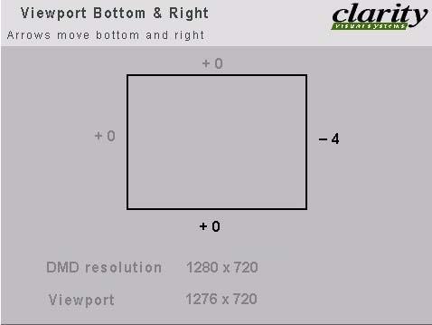
71 3.4.3 Viewport Adjustment The Viewport menus adjust the image on the DMD. What is the DMD? DMD stands for Digital Micromirror Device. It is Texas Instrument s name for their patented chip that produces the pictures in a DLP (Digital Light Processing) system. The DMD chip is about the size of a postal stamp and contains, in the case of Margay, 1280 by 720 pixels. What is Viewport? The Viewport menu adjust the number of pixels actually used on the DMD. You can t increase this number, naturally, but you can reduce it. DMD Resolution shows the resolution of the DMD chip. This has nothing to do with the resolution of the source picture. Viewport shows the number of DMD pixels being used. 60
72 61
73 3.5 Saving Your Work & Recalling a Memory 3.5 Saving Your Work & Recalling a Memory Some saving is done automatically, but there are big advantages to saving your work manually. There is more information about memories starting on page 78. How automatic save works Whatever changes you make with the remote control or RS232 commands, these changes are saved automatically. If you change sources (switch to another input connector) and come back to this source, everything you did before will be recalled. Things will look like they did before. Suppose you make adjustments to an SVGA source on Analog 1, then you feed a UXGA source to Analog 1 and make new adjustments. Then you switch to the S-Video 1 connector and do some more setup for it. Later you switch to the Analog 1 input again, and this time it has the SVGA source from before. The Margay will recognize that it has seen this source before, or at least a source with these characteristics, and will recall the SVGA settings you established before. This kind of recall includes Input Levels, Position, and Frequency, but it does not include Wall Mode and any Big Picture adjustments you made. Those need to be recalled from memory slots. Use the left-right arrow keys to navigate along the line. Use the up-down keys to change the character at that point. Press PREV when finished. Then select Save Now and press ENTER again. If you have RS232 control, there are commands to send a string name to a memory slot, saving time. How to recall a memory slot 1. Press SAVE once to open the Recall grid. 2. Navigate to the slot you want to recall. You can only land on slot numbers that are not empty (have checks). Press ENTER to open the Recall detail menu. If this slot number has exactly the same settings are currently being used, a (Current) message appears on the top line. 3. The only line you can select is Recall Now. Press ENTER. The best practice is to recall settings from memory slots. It is faster. Manually saving to memory slots Margay has 40 numbered memory slots, and this is the best way to save. Recall is fastest from memory slots. First, set up the Margay the way you want it, including all the adjustments listed in this section. Then press the SAVE button twice. This opens the Save grid. Navigate to an unchecked slot number, or to a checked slot if you want to overwrite what s already saved. Press ENTER. This menu shows all the data that will be saved. You can t change anything but the name in this menu. To save immediately, press ENTER. The appearance of this menu is somewhat different for digital and video sources, reflecting what is saved for them. To change the name of the memory slot The default name is an abbreviated description of the contents. In this case, the name tells you that the source is connected to Analog 1, which is an XGA picture. This cube is part of a 2x2 wall, and it s the cube lower left corner (column 1, row 2). If your customer wants or needs a more descriptive name, select the Name line and press ENTER. 62

74 ENTER ENTER 63
75 3.5.1 Memory: What Is Saved? And Where? Margay s automatic memories work well, but the best way to save and recall is with the numbered memory slots, because they recall everything. In the Margay some parameters (values) are associated with the mode. The mode is primarily the horizontal and vertical resolution and the vertical frequency of the incoming source picture. It is more than this, but if you think of it this way, you will be close enough. Some parameters are associated with the input. The input in this instance means the input connector: Analog 1, Analog 2, Digital, Composite Video, etc. Some parameters are global, that is, they are not associated with either the mode or the input connector. They are universal. Parameter ASCII Response Term. ASCII Response Type Auto Codes Auto Lamp On Baud Rate Beeper Black Level: R, G, & B Brightness (video) Color Balance (all values) Colorspace Contrast (video) Curtain Pattern Do Black/White Levels Do Frequency Do Phase Do Position Frequency Gamma Group ID Hue Inverted Installation Justify Lamp Saver Menu H Position Menu Timeout Specific to the Mode Input x x x x x x x Global x x x x x x x x x x x x x x x x x x Parameter Menu V Position Overscan Phase Plug and Play (EDID) Position, Horizontal Position, Vertical Resolution, Horizontal Resolution, Vertical Retry On Lost Signal Saturation Scale Mode Sharpness Terminate RS-485 Unit ID Viewport Window Bottom Viewport Window Left Viewport Window Right Viewport Window Top Wall Height Wall Mode Wall Unit Column Wall Unit Row Wall Width White Boost White Level: R, G, & B Zoom Window Bottom Zoom Window Left Zoom Window Right Zoom Window Top Specific to the Mode Input Global x Memory The Margay remembers that last 10 modes it received and all the mode parameters associated with them. Switching modes For instance, suppose you set up the Black and White Levels for a 65Hz vertical from a x x x x x x x x x x x x x x x x x x x x x x x x x x x x 64
76 computer connected to Analog 1. Then later, using the same input connector but a different computer you set up the Margay for a 60Hz. You re-adjust the Black and White Levels, because they are different. Still later you plug in the first computer with its 65Hz picture. Immediately, the Margay recognizes that it has seen this signal type before, and it recalls the Black and White Levels from its internal memory. It does not Do Frequency or Phase or anything else, because it recognizes that this input was used before, and the previous settings are probably correct. The change is immediate. There is no waiting for the Margay to Do Frequency or Do Phase or any of that. The switch includes the correct input connector. The memory slots can be named something specific to your application: COMPUTER XL-61, MAIN DVD PROGRAM. And there are 40 of them, not just 10. Possible issue with Mode specific memory Suppose that after setting up the 1024x768 and 1600x1200 pictures, you connect a third computer that is 1024x768, but it has a different requirement for Black and White Level. In this case, the Margay would use the wrong values for these levels. To prevent this from happening, use the memory slots as described below. Switching input connectors Now suppose you use Analog 2 to bring in a picture that uses the component YPbPr video. You change the Colorspace setting to YPbPr. If you switch back to Analog 1 in the Picture menu, the Margay switches back to the RGB Colorspace, because Colorspace is specific to the input connector. Possible issue with Input specific memory What happens if you switch back to Analog 1 and the picture there is YPbPr? The Margay has no way to know this, no way to detect the difference between RGB and YPbPr, so it will use the wrong Colorspace. To prevent this from happening, use the memory slots as described below. Global parameters In none of the examples above does the Margay try to change the Baud Rate or the Color Balance values, because these items are saved globally. Memory slots The Margay has memory slots, 40 of them. Each slot memorizes all the mode specific and all the input specific parameters as well as the input connector used. When you recall a memory slot, you recall exactly the way the Margay was set up when the memory was saved. 65
77 66
78 4 Operating 4.1 Selecting a Source Normal Start Up Controlling Margay with Remote Controlling Margay with RS232/RS Asset Tag and Display Status 76 67
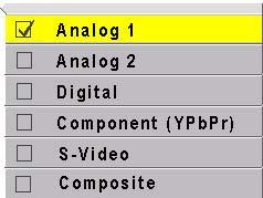
79 4.1 Selecting a Source The source is the picture coming into the Margay. It may be from a computer, a video, or a DVD player. Selecting the source 1. Press MENU on the remote. 2. Select PICTURE and press ENTER. 3. Select SOURCE and press the left ARROW key. 4. Choose the source you want and press ENTER. 5. Press MENU again to close all menus. Selecting a source means choosing an input connector so you can see the picture coming into that input. If the source you select is not there, you will see a Source Absent message on the screen. This usually means there is no picture coming into that connector, or the picture is not valid. This message means Analog 2 is selected now, but there is no picture coming to that connector. 68
80 69
81 4.2 Normal Start Up It is often helpful to know what the sequence of events is when the Margay starts. Start up sequence When AC power is turned on, it seems that nothing happens for a few seconds. The electronics module is starting up and initializing itself. Next, if the optical engine is warm, the fans start. During this time, you cannot turn the lamp on. It shortens lamp life to turn it on when it is hot, so the fans run for a minute or so to be sure it is cool. (There is a temperature sensor on the optical engine. If it is cool enough, the cool-down period is skipped.) After this cooling down period, you can turn on the lamp. If Auto Lamp On is checked in the Miscellaneous menu, the lamp will strike (begin to turn on) at the end of the cooling period. Shut down sequence When you turn off the lamp, the fan continues to run for 15 seconds to cool it off. The lamp fan runs continuously when the lamp is one, and for 5 minutes after the lamp is turned off. The intake fan runs: during Lamp On, for 15 seconds after AC power is applied, during which time you cannot turn on the lamp, and for 15 seconds after Lamp Off. CAUTION It is bad practice to turn off the Margay by turning off the AC power. The lamp does not cool properly. This may shorten lamp life. 70
82 71
83 4.3 Controlling Margay with Remote You can control Margay with the remote control or with RS232 commands. Remote control The remote control projects a series of IR (infrared) pulses to the Margay for control. Aim the remote control at the screen and press MENU. The main menu should be visible, if the lamp is on. Something is blocking the IR receiver in the Margay. IR remote action was disabled by an RS232 command. The remote control has a large spread of its IR radiation. It is difficult from a distance to control only one Margay in a wall. Step closer. For a complete list of all remote actions, see 7.2 Remote Control Buttons on page 116. Beeper If Beeper is checked in the Miscellaneous menu, the Margay will make a beep each time a remote button is pressed (and the Margay receives the signal). If the Margay cannot perform the requested action, it will beep three times, a triple beep. Triple beep will happen whether Beeper is checked on not. If the remote doesn t work The batteries in the remote are dead or installed wrong. The remote was not aimed at the screen. 72
84 73
85 4.4 Controlling Margay with RS232/RS485 Connect the RS232 In to the computer. Loop thru with RS485. Remote control with serial commands is a good way to control a wall while it is operating. It s also an easy way to control Margays in a wall during initial setup using one of the Planar utility programs. To address all the cubes with a certain Unit ID, use an address like *0 or *3. Open Planar s website in your internet browser. In the top banner, click on LOGIN. This opens a new window. Click on the lower, blue LOGIN NOW button for Consultants and Designers. The User Name is tech. The Password is help. Click OK to open the window with all the manuals, utility programs, FRUs and firmware updates. Utility programs available: Cube Control Diag Serial Talk OnOffer and more Cube IDs When the cubes are connected in a series loop (2.5.4 Connections, Control: RS232 & RS485 on page 28), each cube should have a unique ID. The ID is set in the Serial Settings menu. The Group ID and the Unit ID go together to make the cube s ID. Each of the two parts has a range for characters from 0 to 9 and from A to Z (not case sensitive). Addressing the cubes When you send a command, it will have an address. There are five forms of the address. To address all the cubes in this serial loop, use ** for the address. To address a single cube, use the specific ID of that cube, such as A6 or 00 or 1B. To address all the cubes with a certain Group ID, use an address like 3* with will address all the cubes with the Group ID of 3, but with any Unit ID. If you have three walls, and all the cubes in one of the walls have Group ID 3, this type of command would address only this wall. Baud rate Each cube s baud rate must be set to the computer or controller s baud rate. The baud rate is not automatically established, as it is in modems. Terminating the series If the serial string is very long, you may have to terminate the last cube in the string for good communication. Check the Terminate RS485 box. In most instances, this is not necessary. Terminating the string unnecessarily can cause its own communication problems. The guide line is: If it works without terminating, leave it alone. ASCII settings are explained in the RS232 manual for Margay, available or the website. Document All the serial commands are in this document, too. This and other documents are available from Planar s website. 74
86 75
87 4.5 Asset Tag and Display Status The Asset Tag feature allows you to identify each Margay by its serial number or in other ways. To see the current Asset Tag, press MONITOR. Interlock If the interlock is Open, the lamp will not light (unless the interlocks have been bypassed to service the display). Mode ID the number of the mode (type of signal) currently set HPer the horizontal period in nanoseconds (ns) of this signal (picture) VLines the number of vertical lines in the picture This number will be larger than the vertical resolution, because it includes vertical blanking lines that are not visible. Last Fault the last event that caused that forced the lamp off, followed by the number of hours and minutes since that happened, measured in System Hours, not clock time The Asset Tag is initially blank. You can write in any short text message using RS232 commands. See the Margay RS232 Guide, available from Planar s website. Open Planar s website in your internet browser. In the top banner, click on LOGIN. This opens a new window. Click on the lower, blue LOGIN NOW button for Consultants and Designers. The User Name is tech. The Password is help. Click OK to open the window with all the manuals, utility programs, FRUs and firmware updates. Display Status menu information Margay the name of this product the part number for the firmware in Margays Rev the revision number of the firmware currently operating in this Margay Optical Engine SN the serial number read from the optical engine in this Margay Asset Tag a text line you enter (see above) Planar recommends you enter the serial number of this Margay here, unless your facility has a special method of identifying property. PS Fan and Eng Fans If these fans are not on, the lamp will not be on, and you wouldn t be able to see this menu at all. Lamp same for this item. 76
88 5 Troubleshooting 5.1 Troubleshooting Tips Reading the On Screen Code Reading the LEDs 82 77
89 5.1 Troubleshooting Tips Margay has several troubleshooting aids. On Screen codes The On Screen code is a series of red and amber lights that can flash on the screen to tell you what is wrong. These flashing lights are particularly helpful when the lamp won t light. See 5.2 Reading the On Screen Code on page 80. Inside LEDs The LEDs on the electronics module give you information about the state of the Margay. See 5.3 Reading the LEDs on page 82. General troubleshooting Exchange parts from one display to another. This is a very effective way to find a problem. If the problem follows the part to the new unit, that part was at fault. If the problem stays in the first unit, you haven t found the problem yet, but you have learned something: The part you move was not the problem. Put it back in the original unit and try something else. Lamp won t light Check to make sure the lamp is actually not lit. If the lamp is lit, you can usually see light if you look carefully. Light may come through spaces between parts Many things can make the screen black, even though the lamp is lit. The Curtain may be on. If the curtain is black and it is on, the screen will be black. There is no source picture. With no valid picture coming in, the display will be black. There is something blocking the light to the screen. Is the lens cap on? There are parts missing in the optical path. If someone was working on the display, maybe he or she forgot to put something back in. If the lamp is not lit: No AC coming in? Check the main AC switch on the display. It should be lit. No ballast power? Some displays have a green LED near the main AC switch that lights when the 350 volt part of the power supply is working. It should be lit. Other displays may have an LED on the electronics module to show when this high voltage power is available. WARNING Always turn off the AC power and remove the power cord before working inside the display and before removing a lamp. If you have AC and ballast or 350V power, try swapping the lamp into a display where the lamp is good. Lamp A doesn t work here. Display A Display B Move Lamp A here. Move good Lamp B out temporarily. a. If Lamp A works in Display B, put it back in Display A. Lamp A is OK. b. If Lamp A does not work in Display B, the problem is Lamp A. Put a new lamp in Display A. If the lamp is OK, try swapping the ballast in the same way. The lamp ballast provides power to the lamp. It is an electronic part, and all electronic parts are eventually subject to failure. Fan failed. Most fans are sensed. That means theelectronics module knows whether they are running or not. If they don t run when they should, the electronics module turns off the lamp and prevents it from striking (turning on) again. Swapping other parts You can swap electronics modules or fans in the same way to see if one is bad. When you swap electronics modules, try to put them back in their original locations. Otherwise you may have to do setup procedures again, such as Input Level adjustment and Color Balance, because these values are stored in the electronics module. When you swap fans, always exchange fans of the same size. Why not use a new part out of the box? It may seem like a good idea to take a new part out of the box and substitute it for a suspected part in the 78
90 display. However, there is a very tiny chance that the part in the box doesn t work. If you test a part by putting in a known good part, you get better information. 79
91 5.2 Reading the On Screen Code Red and amber lights flashing on the screen can tell you what is wrong. Turning on the On Screen code With the remote control, press MONITOR. You should see the red or amber lights flashing on the screen. This also opens the Display Status menu, but of course, you won t see it if the lamp is off. Automatic On Screen code display If Auto Codes is checked in the Miscellaneous menu, the code will start showing whenever there is a fault event that forces the lamp off. If there is a bright picture, it may be difficult to see these lights. They are soft, out of focus lights. Move around to see them. Or, press CURTAIN to make the screen black so they will be easier to see. If you see a steady, unblinking, amber light, it means the lamp is on and there are no alarm conditions. If the screen is black at this time, there are other reasons for it being black: The curtain is on and black. The source itself is a black picture. There is no source, which turns the screen black. There is some foreign object blocking the light path. 80
92 Margay On-Screen Codes Condition Priority Each block represents 0.2 seconds Starts with Red Lamp is off Starts with Amber. Door open 1 R R R R Power Supply Fan failed 2 R Amber R DLP Fan failed 3 R Amber R 350V failed 4 R R Amber Optical Engine failed 5 R R Amber R Lamp failed 6 R R R Lamp off (wait, auto off) 2 7 R R Amber Amber Wait (lamp off, cooling) 8 R R R R R Lamp off (lamp saver) 3 9 Amber Amber R Lamp off (ready to turn on) 10 Amber Amber Lamp striking (starting) 11 Amber Amber Amber Lamp on, no alarms 12 Amber on continuously R = Red To show the code, press MONITOR button once. 1 With Priority 1-6, to turn lamp on, cycle AC power off, then on. If Auto Codes in the Miscellaneous menu is checked, events with Priority 1-5 starts the On-Screen Code automatically,. 2 Lamp Saver turned lamp off; lamp are cooling and will turn on at end of cooling period. 3 A Lamp On command from the remote or from RS232 commands will turn lamp on. See Footnote 1 81
93 5.3 Reading the LEDs The LEDs on the electronics module can give you more detailed information about the Margay s state. To see LEDs The LEDs are on the electronics module. From the rear, you can see them easily, that is, if there aren t too many cables in the way. LEDs From the front, open the screen. Then open the electronics module door to the right. 82
94 LEDs in Margay When the LED is LED Name Off Green Amber Red Ready Lamp is on (or no power) Source Source absent Valid source present Source absent or not valid Lamp Lamp off Lamp on Lamp striking Lamp failed Fan Fan off Fan is running Remote IR Not receiving IR now Receiving IR radiation Fan failed recently, but is now running Fan failed Lamp disabled Door Open (refers to rear panel and electronics module door) No power to electronics Door closed & rear panel closed Lamp enabled Either door was open, now closed Must cycle AC power to reset and enable lamp Either door open Lamp disabled Serial Data Serial Cmd No command received Received any command Received command meant for me Lamp Saver Lamp Saver not active or lamp is off Lamp Saver active Source present Lamp on Active Lamp is cooling Source present Lamp will come on when cooled Active Source absent Lamp off Optical Engine Status Optical engine OK Optical engine fault or communication failure Ballast Status 1 Lamp off Lamp on Ballast fault or communication failure Ballast Supply 2 High voltage (HV) off HV on and ready HV on but not ready Had to wait more than 10 seconds for ready state 1. At this writing, Ballast Status LED is not implemented, so it is always off. 2. At this writing, Ballast Supply LED will show Red state only briefly. 83
95 84
96 6 Maintenance for Margay 6.1 Changing a Lamp Changing the Air Filter Cleaning the Screen and Mirrors 90 85
97 6.1 Changing a Lamp You can change the lamp from the front or the rear. When should I change the lamp? Change the lamp when it fails. Lamp life is the median life of a large sample of lamps. Median means middle. It is not what most people think of as average. Suppose the specification for lamp life is 5000 hours. If you had a large group of these lamps, more than 100, and you turned them all on at the same time, after 5000 hours at least half of them would still be on. Suppose 50 of these lamps had failed after only 1 hours of use. Then suppose the rest of the lamps failed after 5001 hours. The average life of these lamps would be 2501 hours. But the median life specification is still valid, because at least half of them lasted 5000 hours. This is the way all lamp manufacturers specify lamp life as the median, not the average. Taking a different case, suppose the first 50 lamps failed at 1 hour and the rest of them lasted 10,000 hours. The specification is still valid, because at least half of the lamps were still working after 5000 hours. You can t tell from the lamp life specification how long any one lamp will live. Margay lamp life The median lamp life for the Margay lamp is 6000 hours. If you routinely change the lamp at 6000 hours, you may be throwing away thousands of hours of useful life. And you may be replacing it with a lamp that is destined to last less than 1000 hours. 4. Loosen the screw on the light shield. 5. Lift the cover and latch it. How to change the lamp from the front 1. Open the screen. (See Opening or Removing a Screen on page 34.) 2. Open the door covering the electronics module (on the right). 3. Turn off the AC power switch and remove the power cord 86


98 6. Loosen the lamp screw to the right rear of the lamp. 3. Loosen the lamp screw. 4. Pull the lamp toward you and to the right. 5. Disconnect the lamp cable. Replacing the lamp 1. First, plug in the lamp cable. Be sure it is fully seated. WARNING If the lamp cable is not fully seated on the lamp plug, the lamp will not operate properly. Overheating may occur. 7. When the screw is loose, move the lamp to the rear about 3/8" (10 mm), then to the left, and lift it out, still connected. 8. Disconnect the lamp cable. 2. Then mount the lamp in its place. Note the two pins opposite the lamp screw. These fit into holes in the optical engine. 3. Close the system following the removal steps in reverse. Resetting lamp hours It is a good idea to reset the lamp hours to zero when you install a new lamp. (See Diagnostics: Hours on page 107.) This is not absolutely necessary; it is just a way for you to keep track of lamp use. Removing the lamp from the rear 1. Turn off the AC power switch and remove the power cord 2. Remove the rear panel (6 ¼-turn screws). How to maintain lamp life There are some actions that can shorten lamp life: Turning off AC power when the lamp is on. (Turn off the lamp with the remote and let it cool until the fans stop; then turn off AC.) Turning a lamp on and off rapidly. (The lamp should be allowed to heat up fully before turning it off, at least three minutes.) 87


99 6.2 Changing the Air Filter Clean, cool air is essential for proper Margay operation. When should I change the air filter? When it gets dirty, change it. Unfortunately, there is no absolute rule about when to change an air filter. For some installations the environment has clean, dust-free air, such as a corporate lobby. The air filter may be good for a year or more. In other environments airports, subway terminals the air full of dust and dirt all the time. The air filter might have to be changed every month. Of course, it also depends on how many hours per day or per week the lamp is on. How to determine a changing schedule. Remove and inspect the air filter after three months of operation. Make a note of the air filter s condition. Then check it again after six months of operation. These two inspections will give you some idea of how often the filter needs changing. If it doesn t need changing after six months, inspect again in a year. As long as the environment doesn t change, you can build an appropriate schedule in this way. If new construction occurs in the vicinty of the Planar displays, watch out. New construction usually means DUST. 3. Loosen the light shield screw. Lift and latch the light shield in its up position. 4. Lift out the air filter, tilting it forward as you lift. Removing the air filter from the front 1. From the front, open the screen. (See Opening or Removing a Screen on page 34.) 2. Open the electronics module door. Turn off the AC power switch and remove the power cord. 88
100 Removing the air filter from the rear 1. Turn off the AC power switch and remove the power cord 2. Remove the rear panel (6 ¼-turn screws). 3. Push open the electronics module door. 4. Reach around through this door and loosen the light shield screw. 5. Push the light shield up until it latches out of the way. 6. Lift the air filter up and forward, away from you. 89
101 6.3 Cleaning the Screen and Mirrors Dirt is everywhere, and unless the displays you service are in a super-clean room, from time to time you will have to clean the screens, mirrors and lens of Planar displays. What cleaning product should I use? How should I use them? How often should I use them? Cleaning products and how to use them For mirrors and screens, a foam spray cleaner seems to work well. It s is sold under different names in different parts of the world. It is available from many janitor supply companies or building maintenance supply companies. Ask for Claire #50 glass cleaner, or Sprayway #50 glass cleaner It is probably sold under a local name, but it all comes from one company. If you ask for either of the two names above (it is sold under both), you will get this cleaner under the local name. This cleaner is good on glass (screens, lenses, mirrors) and acrylic (screens). Spray it on the mirror, but not on the screen. For screens, spray it on the cloth, not the screen. WARNING DO NOT spray liquid of any kind on the screen. It can drip down the screen and wick up between the layers. When liquid gets between the screen layers, it is impossible to remove, and the screen is ruined! Wipe the mirror or screen gently with a lint-free cloth or lint-free paper (see Cloth below). Turn the cloth over to the dry side and continue wiping to take up the haze. Glass Wax is another good cleaner for mirrors and glass screens, but it does not work well on acrylic screens. It is a liquid in a can. You spread it on, let it dry, then wipe it off. Windex works well, too. Just don t spray it on the screen. (See Warning above.) Paper towels tend to leave lint. A better paper towel for cleaning is Scott Shop Towels. These blue, lint free, paper towels are generally available at auto parts stores, home fix-it stores, and hardware stores. Cheesecloth is another good choice. This openweave cotton material is light and absorbent. Removing dry dust Often the cleaning problem is just dust, not fingerprints or other oily dirt. If it s just dust, wiping with a dry cheesecloth or a dry Shop Towel will usually do the job. Or use one of the cleaning products designed specifically for picking up dust. Pledge Grab-It, from Johnson Swiffer, from Proctor and Gamble These are synthetic wipes that have a static charge that holds onto dust. They do a very good job of picking up dust and leaving no lint behind. However, they will not wipe away grease or oil, such as fingerprints, and they can t be used with liquid cleaners. Cleaning lenses Clean lenses as you would the glass mirrors. However, because the lens is small, it is easier to spray the cleaner, if you use one, on the cloth, not the lens itself. Where is the dirt? When you see dirt in the picture, you can sometimes tell where it is by its focus. Use a white test pattern to see the dirt most easily. Small specs of dirt or dust that are in very sharp focus are on the screen itself. If the dirt is in soft focus, it is probably a smudge on the large mirror. Dirt on the output lens cannot be seen in the picture. However, that does not mean you should not clean this lens. Dirt here will reduce the brightness of the picture, but it won t show up as specs in the picture. Cloth to use White cotton cloth is better for cleaning than colored cloth. The dyes in some colored cloth tend to make it less absorbent. 90
102 7 Reference Section 7.1 Menu Trees 92 Picture 92 Picture: Source Select 93 Input Levels: Analog Sources 94 Input Levels: Digital Sources 95 Input Levels: Video Sources 96 Size & Position 97 Size & Position 98 Aspect Ratio & Wall 99 Memory 100 Memory: Recall 101 Memory: Save 102 Diagnostics: Display Status 103 Diagnostics: RS232 & RS485 Status 104 Diagnostics: Test Patterns 105 Diagnostics: Setup Summary 106 Diagnostics: Hours 107 Advanced Options: Color Balance 108 Advanced Options: Miscellaneous Options 109 Advanced Options: Lamp Settings 110 Advanced Options: Serial Port Settings 111 Advanced Options: Auto Setup Options 112 Advanced Options: Engine Alignment 113 Advanced Options: Menu Options 114 Program Information Remote Control Buttons Drawings Connector Diagrams Glossary of Terms Specifications for Margay Regulatory Certifications

103 7.1 Menu Trees Picture The Picture menu has different items depending on the current source type. You cannot adjust Frequency in Digital pictures, so that item is not in the Picture menu when the selected source is Digital. You cannot adjust Horizontal Frequency in Analog, because that is determined by the source, so it is grayed out. In the Source line, the left-right keys choose the source. Other items can be adjusted if they are not grayed out. The Freq/Phase button opens the Picture menu directly. In most menus, this area describes what the selected (highlighted) function will do or what it is used for. 92


104 Picture: Source Select Press the LEFT ARROW to open the Source choice menu. To select a source manually, highlight Source, press LEFT ARROW key, select the source you want, press ENTER. 93
105 Input Levels: Analog Sources For digital, see Input Levels: Digital Sources on page 95. For video, see Input Levels: Video Sources on page 96. Press LEVEL to open the Manual Levels menu directly. 94
106 Input Levels: Digital Sources For analog, see Input Levels: Analog Sources on page 94. For video, see Input Levels: Video Sources on page 96. Press LEVEL to open the Manual Levels menu directly. 95


107 Input Levels: Video Sources For analog, see Input Levels: Analog Sources on page 94. For digital, see Input Levels: Digital Sources on page 95. Press LEVEL to open the Manual Levels menu directly. 96


108 Size & Position Zoom Window is in two parts. Each part lets you control two sides of the picture using the arrow keys. Zoom is very limited if the Margay does not have the Big Picture key. Reset All Windows to Default makes all Zoom values zero. If Big Picture is being used and Wall Mode is on, the Zoom values go to the Big Picture defaults. 97

109 Size & Position Viewport shrinks the picture. In the example menu, the right side was pulled in 4 pixels. At the bottom of the menu, Viewport indicates that only 1276 of the DIDs 1280 pixels are being used. This feature is most useful when each cube in a wall is fed a separate picture from a video processor. In such a case, you can t zoom the picture smaller, but you can shrink the picture with Viewport. Reset All Windows to Default makes all Zoom and Viewport values zero. If Big Picture is being used and Wall Mode is on, the Zoom values got to the Big Picture defaults. 98
110 Aspect Ratio & Wall Press the LEFT ARROW to open the Scale Mode choice menu. Wall Width and Height determine the dimensions of the Big Picture wall, which is not necessarily the same as the physical wall (it could be smaller). The upper limit is 32 cubes in each dimension. However, this does not mean you can safely stack Margays 32 cubes high! Unit Column and Row designate where this cube is in the defined wall, which is not necessarily the same position as in the physical wall. The Column can never be larger than the Width, and the Row can never be larger than the Height. When Wall Mode is checked (on), each cube shows only its segment of the whole picture. When Wall Mode is unchecked (off), the cube shows the entire picture. When the aspect ratio of the source picture and the aspect ratio of the cube (or the whole wall when in Wall Mode) do not match, Scale Mode and Justify are used to fit the picture onto the cube (or wall). Scale Mode is Fill All, Crop, Letterbox/Pillarbox, Widescreen, Normal Video or One to One. Fill All stretches the picture as necessary on one axis to fill the screen. All of the picture is shown. Crop fills the screen by zooming until the second edges touch the screen edges and crops the rest. Some of the picture will be cut off. Letterbox/Pillarbox fills the screen by zooming until the first edges touch the screen edges (sides or top-bottom) and leaves the rest of the screen filled with the Curtain color. All of the picture is shown. Widescreen (16x9) forces a 1.77 aspect ratio to display compressed DVDs correctly. All of the picture is shown. Normal Video (4x3) may be the best choice for standard video sources, such as PAL and NTSC. One to One puts the original picture up pixel for pixel. Its shape and size will depend entirely on the source. VGA sources will be small. Justify moves the picture to the top, middle or bottom, or to the left, center or right. This has no function when the Scale Mode is Fill All. 99

111 Memory See Memory: Recall on page 101. See Memory: Save on page 102. The Delete menu looks like the Recall menu. It is not necessary to delete a memory slot before saving something new. 100

112 Memory: Recall In the Recall grid menu, use the arrow keys to navigate through the memories that have something stored in them. The empty memory slots are grayed out and you can t land on them. Press ENTER to open the Recall detail menu. The detail menu shows what will be recalled when you press ENTER. When (Current) appears in the Slot to Recall line, it means that the Margay is already doing exactly what this slot would tell it to do. ENTER Press SAVE once to open the Recall grid directly. 101
, as shown here, if the slot already has something in it.")

 appears if the Save to Slot number currently has something saved in it. To save, highlight Save Now and press ENTER.")

113 Memory: Save Press SAVE twice to open this menu directly. ENTER In the Save grid, use the arrow keys to cycle through the available memories. As you navigate through all 40 memories, Save Now will show (Overwrite), as shown here, if the slot already has something in it. For each empty memory, the Name of the memory is the default name for this slot. You can change this name as described below. Many lines are grayed out because you can t change anything here except the name of the memory. The lines in this menu are different for saving different modes: video or digital. (Overwrite) appears if the Save to Slot number currently has something saved in it. To save, highlight Save Now and press ENTER. A (Current) notice will appear in Save to Slot to indicate that the save was successful and that the slot now contains exactly what the Margay is doing now. To change the Name of a memory slot, highlight Name and press ENTER. A bar appears below the name which indicates character position. Use the +/ arrows to move the yellow highlight in this bar. Use the up-down arrows to change the character at that position. There are 24 character spaces available. The default name is an abbreviation of the memory contents: connector used, resolution, wall configuration and wall position (if wall mode is on). 102

114 Diagnostics: Display Status The Optical Engine SN is read from the optical engine. The Aspect Tag is a text line you can enter using the appropriate RS232 string command. (Find the Margay RS232 Guide on the Planar Systems website.) 103
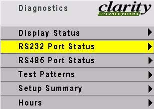
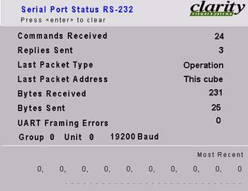
115 Diagnostics: RS232 & RS485 Status 104
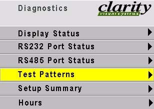
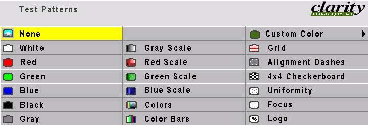
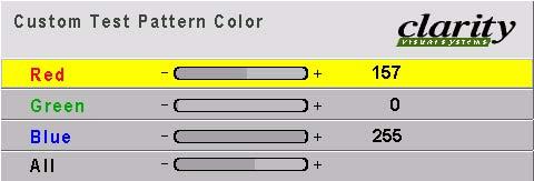
116 Diagnostics: Test Patterns 105
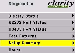
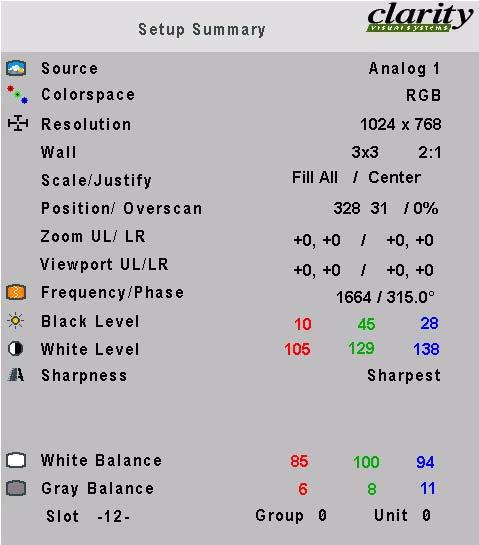
117 Diagnostics: Setup Summary 106
118 Diagnostics: Hours System Time is the number of hours the electronics module has received power. Running Time is the total number of hours any lamp has been on. Lamp is the total number of hours this lamp has been on, that is, if someone reset lamp hours when the lamp was changed. Reset Lamp Hours, when your press ENTER, will reset the Lamp hours, but neither of the other times. 107
 or to Custom.")
119 Advanced Options: Color Balance For a complete description of color balancing, see Color Balancing a Wall of Margays on page 52. Color Temperature sets the color temperature to one of four fixed values (3200K, 5500K, 6500K, 8500K) or to Custom. The fixed temperatures have preset values for all the White and Gray settings and are used primarily in single Margay installations. Custom is the one for color balancing a wall of Margays. Gamma changes the colors slightly for Film or Video display. Use Film for deeper reds. Use Video for optimal brightness. White Boost can increase the brightness of the brightest parts of the picture. Settings are Off, Medium, High. Using this control may alter slightly some of the brighter colors. If used, it should be used on all cubes. It will be more difficult to color balance a wall if White Boost is used. 108
120 Advanced Options: Miscellaneous Options Beeper makes the Margay make a chirping sound each time a remote button is pressed (and received by the Margay). The display always triple-beeps when a button is pressed that tells the Margay to do something it can t do, such as turn on the lamps when they are already on. Curtain Pattern choose what the screen will show when the Curtain button is pressed. Auto Codes causes the Margay to start flashing the On Screen Codes whenever an event causes the lamps to go out, such as opening the rear panel. Plug and Play enables the Extended Display Identification Data (EDID) that is used by many computers to determine the capabilities of the monitor. This is a complicated standard, and not all video card drivers and operating systems act the same. If you are having trouble getting your video card to output a picture when attached to our display, you can try disabling Plug and Play and rebooting the computer, to see if it acts any better. Normally Plug and Play should be enabled. Inverted Installation inverts the menus, the picture, and makes the left-right sense of the image alignment motors switch. Preferred Aspect Ratio tells the Margay which aspect ratio to use when the incoming signal may have several choices. For instance, 1024x768 and 1366x768 have similar signal timings, and the Margay might choose the wrong one. If you application sometimes has 1024x768 but never 1366x768, set this control for 4x3. 109

121 Advanced Options: Lamp Settings Auto Lamp On makes the lamp turn soon after AC power is applied. The Margay must always go through its initialization and sometimes wait for the lamp to cool. Lamp Saver causes the lamp to turn off if there is no source for the specified period of time. When a valid source is re-acquired, the lamp will turn on again. When the lamp turns off, it must cool down. If the source is acquired during this cool-down period, the lamp will turn on after the cooldown period. The Lamp Saver Timeout value ranges from 5 minutes to 24 hours. 110
122 Advanced Options: Serial Port Settings Group ID and Unit ID combine to make the two-character ID for the display. These must be different for each display is a serial RS232 / RS485 control string. The range of each is 0-9 and A-Z. ASCII Response Type and ASCII Response Terminator are explained in the Margay RS232 Guide, available from Planar s website. Terminate: In most instances, this is not necessary. Terminating the string unnecessarily can cause its own communication problems. The guide line is: If it works without terminating, leave it alone. It should only be used on the last display in the string, if at all. 111


123 Advanced Options: Auto Setup Options The checked events occur when the input changes, say from XGA to UXGA a new source is selected you press the SOURCE button. Retry on lost signal, when checked, means the Margay will look for a valid picture on the other connectors whenever sync on the current connector is lost. Margay will stop on the next connector that has a picture (sync). Do Black/White Levels automatically adjusts the lightest and darkest pixels to be white and black. This fully automatic method is prone to errors in the white level. Semi-automatic level adjustment is better. Do Frequency and Do Phase automatically adjust the electronics module to the frequency and phase of the selected picture. Do Position puts the upper left pixel of the picture in the upper left corner of the LCD. 112
124 Advanced Options: Engine Alignment See Adjusting Margay s Engine: Important Step on page 38 for a complete explanation of these controls. 113


125 Advanced Options: Menu Options H and V Position move the location of the menus on the screen. Menu Timeout sets how long menus will remain on the screen before disappearing on their own. The choices are 5, 15, and 60 seconds, and Never Time Out, which keeps the menu on indefinitely. 114
")

126 Program Information Planar Systems, Inc NW Compton Drive Beaverton, OR USA Tel (503) The middle section shows the native resolution of the Margay and the Revision number of the firmware. 115

127 7.2 Remote Control Buttons The function of each remote control button are shown on the next several pages. Turns the lamps on and off. 116

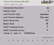
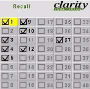
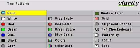
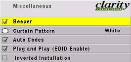
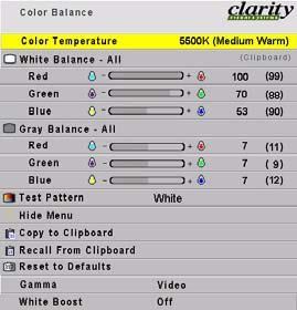
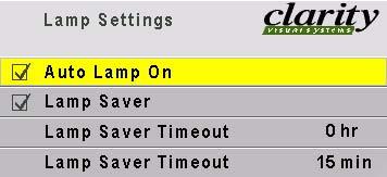
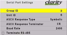
128 Starts scanning the input connectors for the next available source. 117

129 Turns the curtain on and off. Curtain pattern is selected in the Miscellaneous menu. Displays this message See Spreading One Picture Over a Wall on page 54 and starts the process of adjusting the image; performs those steps checked in the Auto Setup Options menu Changes the value of the highlighted item. In some menus, like PIcture Position. these buttons control left-right movement. The + button moves you to the next menu, when there is an arrow in the current highlighted item. 118
130 Opens the Picture menu Selects the previous menu. Selects the highlighted item. If there is an arrow in the item, this button goes to that menu. Moves through the items in a menu. In some menus, such as Picture Position, these button control up-down movement. 119
131 7.3 Drawings All dimensions are in inches. 120
132 121
133 122
134 123


135 7.4 Connector Diagrams These are connector diagrams with pin designations. All connectors on these pages are shown looking at them from the outside, not from the solder side. These diagrams look at the outside of the connector, as the cable sees it, not the wiring side. RS232 adapter DB15 standard VGA connector The wiring shown for this adapter is correct for straight-thru network cables. 1 8 RJ45 looking into the socket. Yellow wire pin 3 Black wire pin 2 Green wire pin 5 RJ45 9-pin Pin Signal 1 Analog Red Out 2 Analog Green Out 3 Analog Blue Out 4 Not connected 5 Ground Ground 7 Ground This little 9-pin to RJ45 adapter is available unwired from many computer or electronic stores. Get one with a female 9-pin connector. The cable must be wired straight-thru. You can tell if a cable is wired straight-thru by looking at its two ends side-by-side. 1. Hold the cable ends next to each other, both ends pointing away from you. Have the clips on both connectors pointing down so you can t see them. 2. If the color of the wires on the two connectors is the same, left to right, the cable is straight-thru. The order of the colors doesn t matter, as long as they are both the same. 8 Ground 9 +5V (DDC) 10 Ground 11 Not connected 12 SDA (DDC) 13 TTL Horizontal Sync 14 TTL Vertical Sync 15 SCL (DDC) 124
 4 TMDS data 4")

136 S-Video connector DVI-I connector Pin Signal 1 Ground (luminance) 2 Ground (chrominance) 3 Luminance 1 V including sync 75 ohms 4 Chrominance 0.3 V burst 75 ohms Pin Signal Pin Signal 1 TMDS data 2-13 TMDS data 3+ 2 TMDS data V power 3 TMDS data 2/4 shield 15 Ground (for +5V, Hsync, Vsync) 4 TMDS data 4 16 Hot plug detection 5 TMDS data TMDS data 0 6 DDC clock 18 TMDS data 0+ 7 DDC data 19 TMDS data 0/5 shield 8 Analog vertical sync 20 TMDS data 5 9 TMDS data 1 21 TMDS data TMDS data TMDS clock shield 11 TMDS data 1/3 shield 23 TMDS clock + 12 TMDS data 3 24 TMDS clock C1 Analog Red C3 Analog Blue C2 Analog Green C4 Analog H sync C5 Analog ground 125
137 7.5 Glossary of Terms Term aspect ratio Meaning The ratio of the width to the height of a picture, often expressed as 4-by-3, 4:3, 4u 3, or 1.33:1 (the aspect ratio of standard television pictures). 16-by- 9 (1.77:1) is the aspect ratio for highdefinition TV. Planar Display Aspect Ratio Term C-Video DA display Meaning Composite video; a video distribution system in which all the video information, is sent on one wire. Distribution amplifier; a device that takes in one input and gives out many of the same type. DAs are available for video, computer and digital signals. One display unit without regard to others that may be in a wall with it. Lion X, UX, XP, UXP, XL, UXL Panther UX, UXP Puma X, XP, UXP Tigress S, X Wildcat S, SE 1.33 DLP Digital Light Processing, Texas Instruments trademarked name for their optical system using a DMD and a color wheel. Other manufacturers also use TI s DMD chips. ballast Bay Cat Bobcat composite sync Lion SX, SXP 1.25 Bobcat 1, Bay Cat, Margay, Bengal 1.77 The electronics part (module) that powers the lamp, providing high voltage to start the lamp and a lower voltage for operation. The name for a Planar direct-view LCD display, similar to a Planar Bobcat, but with a larger screen (46 ) and higher resolution (1920x1080). Model number SN The name for any Planar model beginning SN-4025 or SN A 40" direct view LCD display of pixels. Sync signals that combine the horizontal and vertical syncs onto one signal line, separate from the video. RGBS uses this type. DMD DVI electronics module Fast key H & V sync key Digital Micromirror Device, Texas Instruments trademarked name and patented device for reflecting individual pixels of light toward a screen. Digital Video Interface, a standard for distributing computer pictures in digital form. The electronic part that controls almost everything about the display. It converts incoming pictures to a form the LCD can use to display pictures and provides control through the remote control and RS232 connections to other functions, such as turning lamps on and monitoring fans. One of the buttons on the remote control that takes you directly to a menu or chain of menus. Horizontal and vertical sync on two separate lines. The VGA family uses this type. a push button on the remote control composite video cube A video distribution system in which all the video information, is sent on one wire. Sometimes called C-Video. One display without regard to others that may be in a wall with it. See also unit; display. lamp life LED A lamp life of 5,000 hours means that for a large group of lamps, after 5,000 hours of use, at least half of them will still be operation. Light Emitting Diode: a small, low power lamp used as an indicator, often red or green, but can be other colors. 126
138 Term Meaning Term Meaning Lion Margay module mullion The name for any Planar model beginning WN Model WN , a DLP optical engine with one lamp and a resolution of A stand-alone electronic assembly. Planar displays are designed to be serviced at the module level, not the component level. That is, the technician changes the whole electronics module rather than changing a small part in it. The metal edge surrounding the screen material that holds the screen in place. SECAM slot SOG source stack The television system used primarily in France, Russia and the former Soviet Bloc countries. Sequential Color and Memory. See also NTSC and PAL. A memory location; the numbered location in memory Sync on green, usually for RGB sources A source of pictures, such as a computer, a VCR, a DVD player or the loop-thru from another Planar cube. A group of displays physically bolted together forming a wall. native resolution NTSC PAL Panther power supply Puma The resolution of the LCD or DMD itself. This is the highest resolution the display can show, but in some products the display will accept higher resolutions an The television system used in North America, Japan and parts of South America. It stands for National Television Systems Committee, the group that originally approved it. See also PAL and SECAM. The television system used in most of the world. It stands for Phase Alternation Line. See also NTSC and SECAM. The name for any Planar model beginning WN-6740 or WN The device that converts the mains AC voltage to other voltages that the rest of the display can use. The name for any Planar model beginning with WN-5020 or WN strike SVGA S-Video SXGA sync on green Tigress lighting a lamp or trying to light a lamp Super VGA, a standard for distributing analog computer pictures with a resolution of 800 pixels by 600 pixels. A video distribution system in which the luminance (brightness) and chrominance (color) are sent on separate wires. Short for Super Video. Super extended VGA, a standard for distributing analog computer pictures with a resolution of 1280 pixels by 1024 pixels. The sync part of the signal is combined with the green channel in RGB video. Also called SOG. The name for any Planar model beginning with WN The original Tigress, no longer produced, has been replaced by the Tigress S and Tigress X, whose model numbers start with WN-5230A. remote RGB RGBHV RGBS The remote control. Red, green, blue; three parts of a video signal sent on separate wires. See also YPbPr. RGB plus sync, where H and V sync are on separate wires. RGB plus sync, where composite sync is on a separate wire. unit UXGA VGA One complete display. See also cube; display. Ultra-extended VGA, a standard for distributing analog computer pictures with a resolution of 1600 pixels by 1200 pixels. Video Graphics Adapter, a standard for distributing analog computer pictures with a resolution of 640 pixels by 480 pixels. 127
139 Term video video input module VIM wall Wildcat WXGA XGA Y YPbPr Meaning In this manual, video means NTSC, PAL or SECAM pictures. See VIM Video Input Module: an optional board which plugs into the electronics module that allows S-Video and composite video inputs. A group of displays physically bolted together. (Not possible with Panthers.) The name for any Planar model beginning WN Wide XGA, a standard for distributing analog computer pictures with a resolution of 1280 pixels by 768 pixels. extended VGA, a standard for distributing analog computer pictures with a resolution of 1024 pixels by 768 pixels. One of the components of component video. See also component video and colorspace. Designators for the three conductors in component video. Y = luminace signal Pb = B-Y (blue luminance) signal Pr = R-Y (red luminance) signal 128
140 129
141 7.6 Specifications for Margay Mechanical Specification Maximum Minimum Typical Notes Outside dimensions Width 43.6" mm Height 32.5" mm Depth 17.5" mm Weight 68 lbs 30.8 kg Shipping weight ~85-90 lbs ~38-41 kg Stacking Horizontal unlimited Vertical 4 >10 with support Orientation 15 Tilt on any axis; inverted tilt, same Chassis color Black Ventilation, rear clearance required 0" 0 mm Large walls must maintain adequate air exchange. Screen size (front face) Diagonal 50" 1270 mm Width 43.5" 1105 mm Height 24.5" 622 mm Mullion <1 mm <0.04" Serviceable from front or rear, completely Controls RS232, RS485, remote IR control WallNet ready? Yes Electrical and Heat Specification Maximum Minimum Typical Notes Video input amplitude Separate analog 1.4 V p-p 0.35 V p-p 0.7 V p-p 75 ohm termination Composite analog 5.0 V p-p 0.3 V p-p 75 ohm termination TTL H and V sync 5.0 V 2.5 V 3.5 V TTL at 330 ohm termination In / Out connectors Analog Source1 in and loop out 15-pin D-sub female Analog Source 2 in and loop out Standards accepted DVI Digital Source, DVI transmission std, in and loop out DVI out carries any selected input Optional video module (VIM) Composite video RCA connectors, in and loop out S-video 4-pin DIN connectors, in and loop out Component YPbPr 3 RCA connectors, in and loop out 130
142 Electrical and Heat Specification Maximum Minimum Typical Notes Video standards for VIM RS232 in RS485 in and loop out Frequency Dot clock Horizontal frequency 120 Hz 56 Hz Vertical frequency 91.1 khz khz Sync lock 165 MHz NTSC PAL SECAM HD 480p to 1080i Component YPbPr RJ45 connectors Will not lose sync lock with signal inputs within stated frequency range Maximum input DC offset ±2V AC requirements Line voltage 115 V range 132V 90V Hz auto-ranging, power factor 230 V range 254V 200V corrected Line current 115 V 2.0A 1.5A 230 V 1.2A 1.0A Heat, BTUs per hour 550 BTU Power consumption 160W Optical Specification Maximum Minimum Typical Notes Viewable screen size Diagonal 50" 1321 mm Width 32.5" 826 mm Height 17.5" 445 mm Image position +½ pixel ½ pixel 0 pixel Rotation ½ pixel +½ pixel 0 pixel Pincushion/Barrel 2.5 pixel +2.5 pixel 1.5 pixel After calibration on site Keystoning ½ pixel +½ pixel 0 pixel Focus/Aberration No objectionable defocusing or chromatic aberration at 1.5 screen diagonals by a 20/20 vision viewer Screen High Contrast Acrylic Gain 1.5 Brightness, ANSI white 70 fl white boost off 95 fl white boost on Viewing angle 131
143 Optical Specification Maximum Minimum Typical Notes Resolution Horizontal Vertical Pixel pitch Horizontal ±45 at 5 gain Vertical ±45 at 5 gain 1280 pixels 720 pixels Contrast ratio 1500:1 dark room Viewing angle Horizontal half-gain ±45 Vertical half-gain ±45 Vertical 29.4 pixels/inch (29.4 dpi) pixels/cm (0.86mm dot pitch) Lamp life 6000 hours Median life: at least 50% still operational after 6000 hours Stuck pixels 2 2 stuck dark; 0 stuck bright Screen lamination 1/16" <1.6 mm delamination at edges Environmental Specification Maximum Minimum Typical Notes Temperature operating 40 C 0 C 40 0 C All performance specifications are non-operating 70 C 20 C maintained within this temperature range Altitude (barometric pressure) 10,000 ft 254 m, above sea level, or equivalent barometric pressure Humidity 80% R.H. 20% R.H. 40 C non-condensing 132
144 133
145 7.7 Regulatory Certifications Declaration of Conformity Manufacturer's Name: Manufacturer's Address: declares that the products Model Numbers: Product Options: Planar Systems 1195 NW Compton Drive Beaverton, OR WN (DLP projector) All conforms to the following EU Directives and the standards stated: Safety: UL Safety of IT Equipment Electromagnetic Compatibility Directive 89/336/EEC and amendments EN 55022/CISPR 22 Radiate and Conducted Emissions from IT Equipment EN /EN Generic Immunity Standard Including: EN Electrostatic Discharge EN Radiated Susceptibility EN Electrical Fast Transient Burst EN Surge EN Conducted Susceptibility EN Voltage Dips & Interrupts FCC Regulations This equipment has been tested and found to comply with the limits for a Class A digital device, pursuant to Part 15 of the FCC rules. These limits are designed to provide reasonable protection against harmful interference in an installation. This equipment generates, uses and can radiate radio frequency energy, and if not installed and used in accordance with the instructions, may cause harmful interference to radio communications. However, there is no guarantee that interference will not occur in a particular installation. If this equipment does cause harmful interference to radio or television reception, which can be determined by turning the equipment off and on, the user is encouraged to try to correct the interference by one or more of the following measures: Reorient or relocate receiving antenna. Increase separation between equipment and receiver. Connect equipment to an outlet on a circuit different from that to which the receiver is connected. Consult your dealer or an experienced radio/tv technician. Note: Any changes or modifications to the display not expressly approved by Planar could void the user's authority to operate this equipment. Use of a shielded interface cable is required to comply with the Class A limits of Part 15 of FCC rules. Other Certifications UL, CUL, FCC/CISPR 22/85, CE 134
146 Index A B C D E F G H I J K L M N O P Q R S T U V W X Y Z Numbers 4 3 aspect ratio, definition of, pin to RJ45 adapter, 28 A about menu (program information), 115 AC power requirements, 131 AC connections, 26 AC loop-thru, 26 accessories, 2 adapter, RJ45, 28 adapter, RJ45 to 9-pin, 28 adapter, RS232, wiring of, 124 addressing the cubes, 74 adjusting levels, 44, 46 to computer sources, 44 adjusting to computer source, 44 adjusting to digital source, 48, 50 adjusting video with color bars, 50 adjusting with color bars, 50 air filter, changing, 88 aligning the optical engine, 38 amplitude, video input, 130 analog input, 22 analog inputs, 22 analog inputs, component video into, 24 analog sources, adjusting input levels, 94 arrow buttons, 118, 119 ascii response, 111 aspect ratio, 56, 99 aspect ratio, definition of, 126 aspect ratio, preferred, 109 auto codes, 80, 109 auto lamp on, 110 auto setup options, 44 auto setup options menu, 112 B ballast, definition of, 126 baud rate, 74, 111 beeper, 72, 109 big picture, 99 big picture key, 54 big picture key, installing, 12 big picture key, none, 57 black edge on the screen, 58 black level, 52 black level, digital, 48 black level, manual, adjusting, 46 blue, in color balance, 53 Bobcat, definition of, 126 border color, 57 building the wall, 14 buttons, arrow, 118, 119 buttons, remote control, 116, 117, 118, 119 C cables for RS232, straight-thru, 124 cables, connecting, 22 center point, 46 certifications, 134 changing air filter, 88 choosing the source, 42, 68, 93 cleaning products, 90 cleaning screens, mirrors, 90 color balance hide menu, 52 saving, 53 color balance menu, 108 color balancing, 42, 52 color bars, adjusting video with, 50 color, border, 57 colorspace, 24 column, 99 column in wall mode, 99 component video, 24 component video into analog inputs, 24 composite sync, 22 composite sync, definition of, 126 composite video, 24 composite video, definition of, 126 computer source, adjusting to, 42, 44 computer sources, adjusting to, 44 conformity, declaration of, 134 connecting cables, 22 connector diagrams, 124 connectors, 20, 22 connectors, input, switching, 65 connectors, wiring diagrams of, 124 crop, 56, 99 cube address, 74 cube IDs, 74 cube, definition of, 126 current data in memory, 102 curtain, 118 curtain pattern, 109 C-Video, definition of, 126 D DA, definition of, 126 declaration of conformity, 134 definitions of terms, 126 delete menu, 100 diagrams of connectors, 124 digital inputs, 22 loop-thru, 22 digital black level, 48 A B C D E F G H I J K L M N O P Q R S T U V W X Y Z 135
147 A B C D E F G H I J K L M N O P Q R S T U digital input, 22 digital source, adjusting to, 48 digital sources, adjusting input levels for, 95 dimensions, 130 dimensions, drawings with, 120 display status menu, 103 display, definition of, 126 DLP optical engine, 42 DLP, definition of, 126 DMD, definition of, 126 do black level/while level, 112 do black/white levels, 44 do frequency, 112 do frequency, phase, position, 112 do phase, 112 do position, 112 document number, i drawings, 120 DVI, 22 DVI Out loop-thru from Analog, 22 DVI, definition of, 126 E EDID, 109 electrical specifications, 130 electronics module, definition of, 126 engine alignment menu, 113 engine, optical, aligning, 38 enter button, 119 environmental specifications, 132 F fast key, definition of, 126 FCC regulations, 134 feedback about this manual, v fill all, 56, 99 filter, air, changing, 88 firmware, revision, number of, 115 first row, building, 14 freq/phase button, 119 frequency, specification, 131 G gamma, 108 geometry pattern, 41 global saving, 64 green, in color balance, 53 grid pattern, 41 group ID, 74, 111 H H & V sync, definition of, 126 H position, 114 height, wall, 99 hide menu, 52 high voltage, 4 horizontal frequency specification, 131 hours menu, 107 V W X Y Z I ID, cube, 74 input amplitude, 130 input connectors, switching, 65 input levels, 42 input levels, adjusting for analog sources, 94 input levels, adjusting for digital sources, 95 input levels, adjusting for video sources, 96 installation, inverted, 109 installing, 30 banner, upside down, 18 big picture key, 12 VIM, video input module, 10 installing screens, 32 interlock, electrical, 4 inverted installation, 109 inverted installation in menu, 18 issue input specific memory, 65 mode specific memory, 65 J justify, 57, 99 K key, big picture, installing, 12 key, definition of, 126 keys, arrow, 118, 119 L lamp lamps on in diagnostic code, 81 life, 132 life, definition of, 126 on/off button, 116 lamp hours, 107 lamp life, 86 lamp save, 110 lamp saver, 110 lamp settings menu, 110 lamp won t light, 78 lamp, replacing, 87 LEDs definition of, 126 meaning of, 83 LEDs, reading the, 82 LEDs, table of, 83 letterbox, 56, 99 level button, 94, 116 leveling the screens, 32 levels adjusting, 44, 46 adjusting semi-automatically, 44 Lion, definition of, 127 loop-thru, 22 digital, 22 lost signal, retry on, 112 M manual black level, 46 A B C D E F G H I J K L M N O P Q R S T U V W X Y Z 136
148 A B C D E F G H I J K L M N O P Q R S T U V W X Y Z manual levels, adjusting, 94 manual white level, 46 manual, feedback about this, v manufacturer s address, 134 Margay, definition of, 127 Margay, specifications, 130 meaning of LEDs, 83 meanings of terms, 126 measurement drawings, 120 mechanical specifications, 130 memory current data in, 102 number of, 102 overwriting a, 102 slot, 62 slots, 65, 100, 101, 102 menu about (program information), 115 auto setup options, 112 buttons, 116 color balance, 108 color balance, hide, 52 delete, 100 diagnostics, 103, 104 display status, 103 engine alignment, 113 H position, 114 hours, 107 input levels, 94, 95 inverted installation, 18 lamp settings, 110 miscellaneous options, 109 options, 114 picture, 92 position, 97 program information, 115 recall, 101 RS232 port status, 104 RS485 port status, 104 serial port settings, 111 setup summary, 106 size, 97 test patterns, 105 timeout, 114 trees, 92 V position, 114 zoom, 97 menu options, 114 menu position, 114 menu timeout, 114 mirror, cleaning, 90 misc menu chain, 117 miscellaneous options, 109 model name, location of, 141 model number, location of, 141 modes switching, 64 module, definition of, 127 monitor menu chain, 117 mullion definition of, 127 N name, memory slot, 102 native resolution, 115 native resolution, definition of, 127 no picture, 68 normal video, 99 NTSC, 24 NTSC, definition of, 127 O on screen code, 80 on screen code, table of, 81 on screen codes, auto on, 109 one to one, 99 open screen for work, 36 optical engine, aligning, 38 optical specifications, 131 options, miscellaneous, 109 overwriting a memory, 102 P PAL, 24 PAL, definition of, 127 Panther, definition of, 127 parameters, saved, 64 pattern, curtain, 109 picture menu, 92 picture menu, 92 picture position, 58 picture, source select, 42, 68, 93 pillarbox, 99 pixel pitch, 132 pixels, stuck, 132 plug and play, 109 position, 58 power supply, definition of, 127 power connections, 26 preferred aspect ratio, 109 prev button, 119 products, cleaning, 90 program information menu, 115 Puma definition of, 127 R radiation, UV, 4 reading the LEDs, 82 recall, 62 red, in color balance, 53 regulatory information, 134 A B C D E F G H I J K L M N O P Q R S T U V W X Y Z 137
149 A B C D E F G H I J K L M N O P Q R S T U remote control arrow keys, 118, 119 curtain, 118 delete, 100 enter, 119 freq/phase, 92, 119 lamp, 116 lamp on/off, 116 level, 116 menu, 116 monitor, 117 on/off, 116 prev, 119 recall, 100 save, 100 setup, 118 source, 117 wall, 118 remote control buttons, 116, 117, 118, 119 remote, definition of, 127 removing screens, 30, 34 reset all windows, 97, 98 resolution native, 115 definition of, 127 retry on last signal, 112 retry on lost signal, 112 RGB, definition of, 127 RGBHV, definition of, 127 RGBS, definition of, 127 RJ45 adapter, 28 RJ45 to 9-pin adapter, 28 row in wall mode, 99 RS232 straight-thru cables for, 124 RS232 adapter, wiring of, 124 RS232 connections, 28 RS232 port status menu, 104 RS232, control with, 74 RS485 connections, 28 RS485 port status menu, 104 RS485 terminate, 111 RS485, loop-thru, 74 running time, 107 S safety, 4 regulatory specifications, 134 save, 62 menu chain, 117 save config after color balance, 53 saved globally, 64 saved parameters, 64 saving your work, 62 scale mode, 56, 99 screen delamination, 132 screen shims, 32 screen support, 2, 14 V W X Y Z screen, cleaning, 90 screen, open for work, 36 screens, 30 screens, installing and removing, 30 SECAM, 24 SECAM, definition of, 127 selecting the source, 42, 68, 92, 93 semi-automatic level adjustment, 44 serial number, location of, 141 serial port settings menu, 111 setup button, 118 setup summary menu, 106 shims, 2, 32 signal, lost, retry on, 112 size & position menu, 97 size/pos button, 116 slot definition of, 127 memory, 100, 101, 102 name of, 102 slots, memory, 65 SOG, definition of, 127 source adjusting to, 42 button, 117 definition of, 127 selecting, 92 source absent, 68 source select, 42, 68, 93 source, computer, adjusting to, 44 source, digital, adjusting to, 48 source, video, adjusting to, 50 specifications electrical, 130 environmental, 132 mechanical, 130 optical, 131 specifications for Margay, 130 stack, definition of, 127 standby state indicated in diagnostic code, 81 start up sequence, 70 straight-thru cables for RS232, 124 strike, definition of, 127 stuck pixels, 132 suction cup, 2 support, technical, 141 SVGA, definition of, 127 S-video, 24 S-Video, definition of, 127 swapping parts, 78 switching input connectors, 65 switching modes, 64 SXGA, definition of, 127 sync composite, definition of, 126 H & V, definition of, 126 sync on green, 22 sync on green, definition of, 127 sync, loss of, 112 A B C D E F G H I J K L M N O P Q R S T U V W X Y Z 138
150 system time, 107 T table of LEDs, 83 table of on screen code, 81 technical support, 141 terms used in this manual, meanings of, 126 test pattern, geometry, 41 test pattern, grid, 41 test patterns menu, 105 three beeps, 72 Tigress, definition of, 127 timeout, menu, 114 triple beep, 72 troubleshooting, 78 A B C D E F G H I J K L M N O P Q R S T U white boost, 108 white level, 52 white level, manual, adjusting, 46 Widescreen, 99 widescreen, 57 width wall, 99 Wildcat, definition of, 128 wiring of connectors, 124 words used in this manual, meanings of, 126 work from front, open screen for, 36 WXGA, definition of, 128 X XGA, definition of, 128 V W X Y Z U ultra-violet radiation, 4 unhide Color Balance menu, 52 unit column & row, 99 column & row, in wall mode, 99 unit ID, 74, 111 unit, definition of, 127 upside down, installing a banner, 18 user guide part number, v UV radiation, 4 UXGA, definition of, 127 Y Y, definition of, 128 YPbPr, 24 YPbPr, definition of, 128 Z zoom, 58 zoom menu, 97 V V position, 114 vertical frequency, 131 VGA, definition of, 127 video composite, definition of, 126 definition of, 128 input module, definition of, 128 video controls, 52 video input amplitude, 130 video input module, installing, 10 video source, 50 video source, adjusting to, 50 video sources, adjusting input levels for, 96 viewing angle, 131, 132 viewport, 98 VIM, definition of, 128 VIM, installing, 10 voltages, high, 4 W wall button, 118 definition of, 128 mode, 99 size, 99 wall Height, 99 wall mode, 54 wall width, 99 wall, building the, 14 warranty, iii A B C D E F G H I J K L M N O P Q R S T U V W X Y Z 139
151 A B C D E F G H I J K L M N O P Q R S T U V W X Y Z A B C D E F G H I J K L M N O P Q R S T U V W X Y Z 140

152 Having trouble? Most questions are probably answered somewhere in this manual. Check the Index. If the problem you have is completely baffling, call your Planar reseller the company that sold the Planar display to you. My Planar Reseller is: This is the serial number, the most important number. This is the display s model name and model number. The serial number is some letters followed by numbers, such as LU If you can t contact your reseller for some reason, Planar s contact information is on the back cover of this manual. But first! Get the serial number of the unit you have. The serial number is found on a label in these places: Planar Display Serial Number Label Location from rear from front Bay Cat X on the back panel not available Bengal Bobcat X on right above electronics on the back panel and from edge of the connectors panel next to the power connector on left behind screen, above electronics not available Describe the problem Try to describe the problem in the most precise language you can. Remember, the person you are talking to or writing to can t see what you see. Try to use helpful language. Un-helpful language: It looks funny. The picture doesn t look right. The image is bad. It isn t working. Helpful language: I see horizontal streaks coming from the right side of high contrast edges. I see a solid green background has vertical bands in it. Whenever I try to " ", I get a message on the screen that says " ". The lamp will not turn on. When I changed it with another lamp, it still did not turn on. There is a black line on the left side, and I can t move the picture over there with the Position control. I see flashing red and amber lights on the screen. (Note the sequence of the colored lights. It s important.) Lion Margay on the back panel of the lower section on back of electronics door on the left wall of the Center Bay behind electronics door Puma on the back panel on the left wall 141

153 d 29 Mar 2007 Planar Systems, Inc. All rights reserved 1195 NW Compton Drive Beaverton, OR Main Phone: Technical Support Phone: Fax:
PS4660T and PS5560T User Manual
 PS4660T and PS5560T User Manual Copyright 9 May 2013 by Planar Systems, Inc. All rights reserved. Contents of this publication may not be reproduced in any form without permission of Planar Systems, Inc.
Infinitely Expandable
 A revolutionary MLCD Infinitely Expandable MLCD A revolutionary MLCD MLCD Infinitely Expandable ORION CO.,LTD. www.oriondisplay.net Address: 217, 1gongdan-ro, Gumi-si, Gyeongsangbuk-do, Korea Tel : +82-2-6678-8533,
Indoor/Outdoor Security System with Quad Monitor User s Manual
 Indoor/Outdoor Security System with Quad Monitor User s Manual 4919539 Important! Please read this booklet carefully before installing or using these units. WARNING - These units should ONLY be opened
PL2410W LCD Monitor USER'S GUIDE.
 PL2410W LCD Monitor USER'S GUIDE www.planar.com Content Operation Instructions...1 Safety Precautions...2 First Setup...3 Front View of the Product...4 Rear View of the Product...5 Quick Installation...6
APSPB PUSH BUTTON ZERO Installation Manual
 APSPB PUSH BUTTON ZERO Installation Manual CARDINAL SCALE MFG. CO. 8527-0579-0M Rev A 203 E. Daugherty, Webb City, MO 64870 USA Printed in USA 12/14 Ph: 417-673-4631 Fax: 417-673-2153 www.detectoscale.com
Quick Reference Guide
 Multimedia Projector Quick Reference Guide MODEL 103-011100-01 Projection lens is optional. English Use this book as a reference guide when setting up the projector. For detailed information about installation,
VectorVGA Tempest User Manual
 VectorVGA Tempest User Manual 2 Notice Regarding This Product WARNING! To install this product you should: Be familiar with safe handling procedures for electronic components. Be able to use hand tools
WID-DL74 WID-DL74 BLP WID. Designed for. Installation guide for workitdesk interactive table for. BrightLink Pro
 WID-DL74 WID-DL74 BLP WID Designed for BrightLink Pro Installation guide for workitdesk interactive table BrightLink Pro for Mounting the table unit 1 Unpack boxes 1 of 4 (Mobile base) and 2 of 4 (Motorized
ivw-fd122 Video Wall Controller MODEL: ivw-fd122 Video Wall Controller Supports 2 x 2 Video Wall Array User Manual Page i Rev. 1.
 MODEL: ivw-fd122 Video Wall Controller Supports 2 x 2 Video Wall Array User Manual Rev. 1.01 Page i Copyright COPYRIGHT NOTICE The information in this document is subject to change without prior notice
MaxView Cinema Kit Quick Install Guide
 SYSTEM SETUP The MaxView will work at any of the following display settings: INSTALLATION MaxView Cinema Kit Quick Install Guide Step 1 - Turn off your computer. Disconnect your monitor s VGA cable from
SV-LCD50. Installation and User Guide. Thin-Film Transistor (TFT) Liquid Crystal Display (LCD) Color Rear Vision Monitor. Version 1.
 Liquid Crystal Display (LCD) Color Rear Vision Monitor. Version 1.") SV-LCD50 Installation and User Guide Thin-Film Transistor (TFT) Liquid Crystal Display (LCD) Color Rear Vision Monitor Version 1.00 August 2004 SV-LCD50 Installation and User Guide TFT LCD Color Rear Vision
SV-LCD50 Installation and User Guide Thin-Film Transistor (TFT) Liquid Crystal Display (LCD) Color Rear Vision Monitor Version 1.00 August 2004 SV-LCD50 Installation and User Guide TFT LCD Color Rear Vision
Apple Component AV Cable
 Apple Component AV Cable 1 Component AV Cable Use the Component AV Cable to connect your ipod or iphone to the component video and analog audio ports on your TV, home theater receiver, or stereo receiver.
LavryBlack Series Model DA10 Digital to Analog Converter
 LavryBlack Series Model DA10 Digital to Analog Converter Lavry Engineering, Inc. P.O. Box 4602 Rolling Bay, WA 98061 http://lavryengineering.com email: techsupport@lavryengineering.com January 14, 2008
USER S MANUAL. Deuce HD User's Manual WORLD HEADQUARTERS
 USER S MANUAL WORLD HEADQUARTERS Artel Video Systems 5B Lyberty Way Westford, MA 01886 Tel: (978) 263-5775 Fax: (978) 263-9755 Email: info@artel.com Web: www.artel.com P/N 1219 Rev. F Copyright 2016 USER
USER S MANUAL (1/2) (Functions and connections)
 (Functions and connections)") English USER S MANUAL (1/2) (Functions and connections) WIDE PLASMA DISPLAY P42VCA30W/P42VCA30E WITH OPTIONAL VIDEOBOARD (P-TE1100/P-TE1110/P-TE1120/P-TE1130) HE4VS01W/HE4VS01E WITH OPTIONAL VIDEOBOARD
English USER S MANUAL (1/2) (Functions and connections) WIDE PLASMA DISPLAY P42VCA30W/P42VCA30E WITH OPTIONAL VIDEOBOARD (P-TE1100/P-TE1110/P-TE1120/P-TE1130) HE4VS01W/HE4VS01E WITH OPTIONAL VIDEOBOARD
Kramer Electronics, Ltd. USER MANUAL. Model: VM Video Component Distributor
 Kramer Electronics, Ltd. USER MANUAL Model: VM-1045 Video Component Distributor Contents Contents 1 Introduction 1 2 Getting Started 1 2.1 Quick Start 1 3 Overview 3 4 Your VM-1045 Video Component Distributor
Quick Installation Guide. Indoor / Outdoor Antenna, Antenna Cable & Surge Arrestor H/W: V2
 Quick Installation Guide Indoor / Outdoor Antenna, Antenna Cable & Surge Arrestor H/W: V2 Table of Contents English... 1 1. Outdoor Antenna Installation... 1 2. How to install the surge arrestor... 5 Troubleshooting...
Instruction Guide. The TV Jockey Computer Monitor TV Tuner with Remote COMP2VGATVGB. The Professionals Source For Hard-to-Find Computer Parts
 VIDEO ADAPTER The TV Jockey Computer Monitor TV Tuner with Remote COMP2VGATVGB Instruction Guide * Actual product may vary from photo The Professionals Source For Hard-to-Find Computer Parts FCC COMPLIANCE
User Manual. Model 1365 Video Scaler
 User Manual Model 1365 Video Scaler Model 1365 PC/HD Video Converter Table Of Contents 1.0 Introduction........................3 2.0 Specifications....................... 4 3.0 Checking Package Contents................5
Quick Installation Guide TV-H110 H/W: V1
 Quick Installation Guide TV-H110 H/W: V1 Table of Contents... 1 1. Before You Start... 2. Hardware Installation... 1 2 Troubleshooting... 13 Version 10.15.2008 1. Before you start Installation Requirements
4, 8, 16 Port VGA/ Audio Extender / Splitter With Local Output with SPDIF Model #: VGA-C5SP-8
 4, 8, 16 Port VGA/ Audio Extender / Splitter With Local Output with SPDIF Model #: VGA-C5SP-8 2010 Avenview Inc. All rights reserved. The contents of this document are provided in connection with Avenview
ivw-fd133 Video Wall Controller MODEL: ivw-fd133 Video Wall Controller Supports 3 x 3 and 2 x 2 Video Wall Array User Manual Page i Rev. 1.
 MODEL: ivw-fd133 Video Wall Controller Supports 3 x 3 and 2 x 2 Video Wall Array User Manual Rev. 1.01 Page i Copyright COPYRIGHT NOTICE The information in this document is subject to change without prior
PLL1920M LED LCD Monitor
 PLL1920M LED LCD Monitor USER'S GUIDE www.planar.com Content Operation Instructions...1 Safety Precautions...2 First Setup...3 Front View of the Product...4 Rear View of the Product...5 Installation...6
VGA & RS232 Extender SET over Single CAT5 with RGB Delay Control
 VGA & RS232 Extender SET over Single CAT5 with RGB Delay Control Model #: VGA-C5RS-SET 2010 Avenview Inc. All rights reserved. The contents of this document are provided in connection with Avenview Inc.
P-2 Installing the monitor (continued) Carry out as necessary
 Carry out as necessary") P-2 Installing the monitor (continued) Carry out as necessary Using the monitor without the bezel MDT552S satisfies the UL requirements as long as it is used with the bezel attached. When using the monitor
P-2 Installing the monitor (continued) Carry out as necessary Using the monitor without the bezel MDT552S satisfies the UL requirements as long as it is used with the bezel attached. When using the monitor
CrossLine Generator Operation Manual
 WARRANTY MicroImage Video Systems warrants that each CL5400A is free from defects due to faulty materials or improper workmanship for a period of one (1) year. MicroImage Video Systems further warrants
K Service Source. Apple High-Res Monochrome Monitor
 K Service Source Apple High-Res Monochrome Monitor K Service Source Specifications Apple High-Resolution Monochrome Monitor Specifications Characteristics - 1 Characteristics Picture Tube 12-in. diagonal
VGA / Audio Extender Single CAT5 / CAT6 with RGB Delay Control & EQ
 VGA / Audio Extender Single CAT5 / CAT6 with RGB Delay Control & EQ Model #: VGA-C5A-SET 2010 Avenview Inc. All rights reserved. The contents of this document are provided in connection with Avenview Inc.
User Manual rev: Made in Taiwan
 CV-500S HDMI to Component/CVBS & Audio Scaler Converter User Manual rev: 131218 Made in Taiwan The CV-500S HDMI to Component/CVBS & Audio Scaler Converter has been tested for conformance to safety regulations
Linear Array with Intensity Adjustment
 Datasheet High-Power Lighting with Intensity Adjustment for use with Vision Systems For complete technical information about this product, including dimensions, accessories, and specifications, see www.bannerengineering.com/lineararraylights.
VGA, Audio & RS232 Extender SET over Single CAT5 with RGB Delay Control & IR Pass Through
 VGA, Audio & RS232 Extender SET over Single CAT5 with RGB Delay Control & IR Pass Through Model #: VGA-C5ARS-SET 2010 Avenview Inc. All rights reserved. The contents of this document are provided in connection
AWT150C/AWT150CS/ AWT151C CCD Camera
 AWT150C/AWT150CS/ AWT151C CCD Camera ISSUED OCTOBER 2018 WARNING Failure to follow all instructions and safety precautions in this manual, in the vehicle and body manufacturers' manuals and on the safety
K Service Source. Apple High-Res Monochrome Monitor
 K Service Source Apple High-Res Monochrome Monitor K Service Source Specifications Apple High-Resolution Monochrome Monitor Specifications Characteristics - 1 Characteristics Picture Tube 12-in. diagonal
PLL2210MW LED Monitor
 PLL2210MW LED Monitor USER'S GUIDE www.planar.com Content Operation Instructions...1 Safety Precautions...2 First Setup...3 Front View of the Product...4 Rear View of the Product...5 Quick Installation...6
VGA & Audio Receiver SET over Single CAT5 with RGB Delay Control
 VGA & Audio Receiver SET over Single CAT5 with RGB Delay Control Model #: VGA-C5A-R 2010 Avenview Inc. All rights reserved. The contents of this document are provided in connection with Avenview Inc. (
900-Lumen Portable LED Projector Part #: User manual
 900-Lumen Portable LED Projector Part #: 21797 User manual 900-Lumen LED Projector Manual Page 2 of 14 900-Lumen LED Projector Manual Page 3 of 14! SAFETY WARNINGS AND CAUTIONS WARNING: To reduce the risk
DVI to HD-SDI Conversion Box
 DVI to HD-SDI Conversion Box USER MANUAL www.gefen.com ASKING FOR ASSISTANCE Technical Support: Telephone (818) 772-9100 (800) 545-6900 Fax (818) 772-9120 Technical Support Hours: 8:00 AM to 5:00 PM Monday
User Guide. Video to VGA/HD Converter/Scaler DVI-3420a. Video to DVI Converter/Scaler DVI-3410a
 User Guide Video to VGA/HD Converter/Scaler DVI-3420a Video to DVI Converter/Scaler DVI-3410a TABLE OF CONTENTS SECTION PAGE PRODUCT SAFETY... 1 PRODUCT LIABILITY.... 1 1.0 INTRODUCTION.... 2 2.0 SPECIFICATIONS....
LWX-1. Satellite Weather Radio Module Installation Instructions A
 LWX-1 Satellite Weather Radio Module Installation Instructions 988-0158-13A Copyright 2009 Navico All rights reserved. No part of this manual may be copied, reproduced, republished, transmitted or distributed
HDMI Extender over UTP Cable
 User Manual HDMI Extender over UTP Cable VHDE-300 Tx Rx Features.. Extends HDMI 1080p AV and IR Signals Transmission distance up to 60m/200ft via CAT6 cable or higher grade cable 5V DC, 1A Important Safety
Wide LCD Monitor. User Manual
 Wide LCD Monitor User Manual PRECAUTIONS Information for users applicable in European Union countries 1 Information for users applicable in United States of America 1 1 Power connection 1 Maintenance 1
USER MANUAL. Kramer Electronics, Ltd. Models: VP-413, Video to WXGA Scaler. VP-414, Video to WXGA / HD Scaler. VP-415, Video to WXGA / DVI Scaler
 Kramer Electronics, Ltd. USER MANUAL! Models: VP-413, Video to WXGA Scaler VP-414, Video to WXGA / HD Scaler VP-415, Video to WXGA / DVI Scaler VP-416, Video to DVI-I / HD Scaler Contents Contents 1 Introduction
2013, 2014 Hewlett-Packard Development Company, L.P.
 User Guide 2013, 2014 Hewlett-Packard Development Company, L.P. The only warranties for HP products and services are set forth in the express warranty statements accompanying such products and services.
LA1500R USER S GUIDE.
 LA1500R USER S GUIDE www.planar.com The information contained in this document is subject to change without notice. This document contains proprietary information that is protected by copyright. All rights
CM 930 / DM 960 DM 969 / EM 981 RM 510 PRODUKTINFORMATION PRODUCT INFORMATION INFORMATIONS DE PRODUIT
 PRODUKTINFORMATION PRODUCT INFORMATION INFORMATIONS DE PRODUIT CM 930 / DM 960 DM 969 / EM 981 RM 510 Mikrofonköpfe Microphone Capsules Têtes de microphone INHALT / CONTENTS / SOMMAIRE PRODUKTINFORMATION
VHF + UHF Amplified HDTV Antenna Model OA8000 & OA8001 Installation Instructions Reception Frequencies
 VHF + UHF Amplified HDTV Antenna Model OA8000 & OA8001 Installation Instructions Reception Frequencies VHF: 54-216 MHz UHF: 470-698 MHz FM: 87.9-107.9 MHz Voltage Input: AC110-120V / AC220-240V Working:
R87B. Box Fan. Comprehensive Lineup of Single, Double, and Triple Axial Fans with Easy One-step Mounting. Model Number Structure. Ordering Information
 Box Fan R87B CSM_R87B_DS_E_4_4 Comprehensive Lineup of Single, Double, and Triple Axial Fans with Easy One-step Mounting Mounts in a square cutout and conceals the hole-cut to simplify installation work.
4 x 4 VGA Matrix Switch
 Hall Research Technologies, Inc. 4 x 4 VGA Matrix Switch Model VSM-404 User s Manual With Serial Keypad CUSTOMER SUPPORT INFORMATION Order toll-free in the U.S. 800-959-6439 FREE technical support, Call
DCL9AW. User Manual. English
 DCL9AW User Manual English PRECAUTIONS Information for users applicable in European Union countries 1 Information for users applicable in United States of America 1 Installation 1 Power connection 1 Maintenance
Warning...1 Safety Precaution...3
 PL1910W Contents Preface...1 Warning...1 Safety Precaution......3 Installation...4 Introduction...4 Features...4 Unpacking...5 Attaching the Base...6 Removing the Base...7 Preparing The Monitor For Wall-Mounting...8
Operating Instructions
 Operating Instructions SDI Input board Model No. AV-HS04M1 РУССКИЙ FRANÇAIS DEUTSCH ENGLISH ESPAÑOL ITALIANO Before operating this product, please read the instructions carefully and save this manual for
PRO-ScalerV2HD VGA to HDMI & Audio Scaler Converter. User s Guide. Made in Taiwan
 VGA to HDMI & Audio Scaler Converter User s Guide Made in Taiwan Congratulations for owning a gofanco product. Our products aim to meet all your connectivity needs wherever you go. Have fun with our products!
VGA / Audio Extender Single CAT5 / CAT6 with RGB Delay Control & EQ
 AV Connectivity, Distribution And Beyond... VIDEO WALLS VIDEO PROCESSORS VIDEO MATRIX SWITCHES EXTENDERS SPLITTERS WIRELESS CABLES & ACCESSORIES VGA / Audio Extender Single CAT5 / CAT6 with RGB Delay Control
TV44. Owner s Manual. Amplified/Outdoor Satellite Dish Clip-on Antenna
 TV44 Owner s Manual Amplified/Outdoor Satellite Dish Clip-on Antenna Safety Precautions 1 Warning! Use extreme caution when installing or removing an outdoor antenna that is located close to overhead wires
PRO-ScalerHD2V HDMI to VGA & Audio Scaler Converter. User s Guide. Made in Taiwan
 PRO-ScalerHD2V HDMI to VGA & Audio Scaler Converter User s Guide Made in Taiwan Congratulations for owning a gofanco product. Our products aim to meet all your connectivity needs wherever you go. Have
User Guide. Single-Link DVI Active Cable Extender. DVI-7171c
 User Guide Single-Link DVI Active Cable Extender DVI-7171c TABLE OF CONTENTS SECTION PAGE PRODUCT SAFETY...1 PRODUCT LIABILITY...1 1.0 INTRODUCTION...2 2.0 SPECIFICATIONS...3 3.0 PACKAGE CONTENTS...4 4.0
MIRAGE. Skyline Mirage Set-Up Instructions Skyline Exhibits
 MIRAGE Skyline Mirage Set-Up Instructions www.skyline.com Table of Contents Mirage Pop-up is available in many sizes from 32 tall tabletops to 92 tall backwalls. The following set-up and repacking instructions
Part names (continued) Remote control
 Remote control") Introduction Part names (continued) Remote control (1) STANDBY ( 25) (1) (2) ON ( 25) (3) (3) ID - 1 / 2 / 3 / 4 s ( 18) (4) (4) COMPUTER 1 ( 27) (7) (5) COMPUTER 2 * (8) (6) COMPUTER 3 * (10) (13) (7)
Introduction Part names (continued) Remote control (1) STANDBY ( 25) (1) (2) ON ( 25) (3) (3) ID - 1 / 2 / 3 / 4 s ( 18) (4) (4) COMPUTER 1 ( 27) (7) (5) COMPUTER 2 * (8) (6) COMPUTER 3 * (10) (13) (7)
Manual No: Revision: D. IQ Box. Software Upgrade Instructions
 Manual No: 577013-834 Revision: D IQ Box Software Upgrade Instructions Notice Veeder-Root makes no warranty of any kind with regard to this publication, including, but not limited to, the implied warranties
3.5 TFT LCD CCTV Service Viewer with Wristband
 User Manual 3.5 TFT LCD CCTV Service Viewer with Wristband LCD35SV It can proved the 12V DC power to camera for easy trouble shoot. LCD35SV is a type of product that summarizes views of first-line safety
hp mp3130 series digital projector user s guide
 hp mp3130 series digital projector user s guide 1 Notice This manual and any examples contained herein are provided as is and are subject to change without notice. Hewlett-Packard Company makes no warranty
4, 8, 16 Port VGA and Audio Extender / Splitter with Audio over Single CAT5
 4, 8, 16 Port VGA and Audio Extender / Splitter with Audio over Single CAT5 Model #: VGA-C5SP-4, VGA-C5SP-8, VGA-C5SP-16 2010 Avenview Inc. All rights reserved. The contents of this document are provided
Kramer Electronics, Ltd. USER MANUAL. Model: RTBUS-11. Round Table Connection Bus
 Kramer Electronics, Ltd. USER MANUAL Model: RTBUS-11 Round Table Connection Bus Contents Contents 1 Introduction 1 2 Getting Started 1 2.1 Quick Start 2 3 Overview 3 3.1 About HDMI 4 4 Your RTBUS-11 Round
User Guide. HDMI Fiber Optic Extender. DVI-7350a
 User Guide HDMI Fiber Optic Extender DVI-7350a Table of Contents Section Page Product Safety.................................... 1 1.0 Introduction...2 2.0 Specifications...3 3.0 Package Contents...3 4.0
Replacing the PanelMate epro PS, PanelMate epro PS Classic, PanelMate epro PS EE, and PanelMate epro PS OD 7685x-15xx Series Backlight Assembly
 Introduction Replacing the PanelMate epro PS, PanelMate epro PS Classic, PanelMate epro PS EE, and PanelMate epro PS OD 7685x-15xx Series Assembly Instruction Leaflet IL04802009E Effective September 2008
Installation Manual SaVi Note Underwater LED Light
 Installation Manual SaVi Note Underwater LED Light Model Numbers SAVI-NOTE7, SAVI-NOTE0 Table of Contents Safety Precautions...2 SaVi Note Install Instructions...3- M Instructions...- Warnings READ AND
45LM Series Modules. Features. Specifications. Plug-in Logic and Display Modules for Q45 Series Photoelectric Sensors
 Plug-in Logic and Display Modules for Q45 Series Photoelectric Sensors Three plug-in modules are available: Features Model 45LM58 45LM58D 45LMD Functions Selectable output timing Selectable output timing,
1x4, 1x8, 1x12, 1x16 VGA Extender / Splitter over Single CAT5
 1x4, 1x8, 1x12, 1x16 VGA Extender / Splitter over Single CAT5 User s Guide Models VGA-C5-SP-4 VGA-C5-SP-8 VGA-C5-SP-12 VGA-C5-SP-16 2009 Avenview Inc. All rights reserved. The contents of this document
Operating Instructions
 Operating Instructions LCDRV700 Digital LCD Color Monitor Please read this manual thoroughly before operating the unit, and keep it for future reference. V1.0 Contents 1. Precautions 2. Features 1 3 3.
Model Number Structure
 Cycle Control Units CSM DS_E_7_1 Refer to Safety Precautions for All Power Controllers. Used in Combination with the to Enable High-precision Temperature Control Use cycle control to achieve power control
User Manual. PC / HD Scaler. with advanced video processing. VGA to Component Video Component Video to VGA VGA to VGA Component to Component
 User Manual PC / HD Scaler with advanced video processing VGA to Component Video Component Video to VGA VGA to VGA Component to Component Model 1366 WARNINGS Read these instructions before installing or
19 / 20.1 / 22 WIDE SCREEN TFT-LCD MONITOR
 19 / 20.1 / 22 WIDE SCREEN TFT-LCD MONITOR V193/ V220 Series V202 Series USER MANUAL www.viewera.com Rev. 2.0 Table of Contents EMC Compliance......1 Important Precautions...2 1. Package contents....3
Kramer Electronics, Ltd. USER MANUAL. Model: VP-100. VGA/XGA to RGBHV Converter
 Kramer Electronics, Ltd. USER MANUAL Model: VP-100 VGA/XGA to RGBHV Converter Contents Contents 1 Introduction 1 2 Getting Started 1 2.1 Quick Start 1 3 Overview 3 4 Your VP-100 VGA/XGA to RGBHV Converter
1X4 HDMI Splitter with 3D Support
 AV Connectivity, Distribution And Beyond... VIDEO WALLS VIDEO PROCESSORS VIDEO MATRIX SWITCHES EXTENDERS SPLITTERS WIRELESS CABLES & ACCESSORIES 1X4 HDMI Splitter with 3D Support Model #: SPLIT-HDM3D-4
INSTALLATION GUIDE. Axle Weighing Truck Scale. 60,000 lb x 20 lb Factory Calibrated Includes Pre-interfaced Wireless Remote LED Scoreboard Displays
 INSTALLATION GUIDE 60,000 lb x 20 lb Factory Calibrated Includes Pre-interfaced Wireless Remote LED Scoreboard Displays V 1.0 OVERVIEW TOOLS REQUIRED Forklift and block Prybar Wrenches: #8 allen wrench,
Sphinx II. Owner s Manual. Tube Hybrid Integrated Power Amplifier. Rogue Audio, Inc. 3 Marian Lane Brodheadsville, PA Issue date: 08/01/16
 Sphinx II Tube Hybrid Integrated Power Amplifier Owner s Manual Rogue Audio, Inc. 3 Marian Lane Brodheadsville, PA 18322 Issue date: 08/01/16 TABLE OF CONTENTS 1) Introduction 2 2) Unpacking the Sphinx
User Manual. Model 9A60A. VGA to Component Video Converter. Made in the USA
 User Manual Model 9A60A VGA to Component Video Converter Made in the USA Table Of Contents 1.0 Introduction........................3 2.0 Installation.........................4 3.0 Troubleshooting......................
User Manual PS-684. HDBaseT Extender Kit 70m. All Rights Reserved. Version: UHBT70P_2016V1.2
 User Manual PS-684 All Rights Reserved Version: UHBT70P_2016V1.2 Preface Read this user manual carefully before using this product. Pictures shown in this manual is for reference only, different model
TV Lift System Model CL-65 Installation Instructions
 TV Lift System Model CL-65 Installation Instructions Contact: Support@Nexus21.com Toll Free: (866) 500-5438 Phone: (480) 951-6885 Fax: (480) 951-6879 Revised: 01/17/17 Below is a parts list describing
VGA CAT-5 1:8 Distribution S VGA CAT-5 Distribution R. EXT-VGA-CAT5-148S EXT-VGA-CAT5-148R User Manual
 VGA CAT-5 1:8 Distribution S VGA CAT-5 Distribution R EXT-VGA-CAT5-148S EXT-VGA-CAT5-148R User Manual INTRODUCTION Congratulations on your purchase of the VGA CAT-5 1:8 Distribution S. Your complete satisfaction
Website: Tel: ADDRESS: 6475 Las Positas Rd. Livermore, CA Item No. E5B/E5S Installation Guide
 Website: www.flexispot.com Tel: -855-4-808 ADDRESS: 6475 Las Positas Rd. Livermore, CA 9455 Item No. E5B/E5S Installation Guide Specifications Step Column 3 Max. Weight Capacity 0 Ibs (00 kg) Speed 38mm/s
CM-S23349SV. Vari-Focal IR Bullet Camera
 Vari-Focal IR Bullet Camera User s Guide CM-S23349SV SAFETY PRECAUTIONS WARNING 1. Be sure to use only the standard adapter that is specified in the specification sheet. Using any other adapter could cause
LINDY ELECTRONICS LIMITED & LINDY-ELEKTRONIK GMBH - FIRST EDITION
 VGA to DVI Scaler Manual LINDY No. 32563 www.lindy.com LINDY ELECTRONICS LIMITED & LINDY-ELEKTRONIK GMBH - FIRST EDITION (Dec 2007) Manual Introduction Thank you for purchasing the LINDY VGA to DVI Scaler.
Extender w/ RS-232 and 2-way IR
 Extender w/ RS-232 and 2-way IR GTB-UHD2IRS-ELRPOL-BLK User Manual Release A3 Important Safety Instructions 1. Read these instructions. 2. Keep these instructions. 3. Heed all warnings. 4. Follow all instructions.
User Manual. Innovative LCD Display Solutions AP-20 Series DP-20 Series OP-20 Series NAP-20 Series
 Innovative LCD Display Solutions AP-20 Series DP-20 Series OP-20 Series NAP-20 Series 1. Table of Content 1. Table of Content P.1 2. Introduction 3. Installation A) Overview P.2 B) Features P.2 C) Dimension
BENESTON USER MANUAL AHD-ER03H. AHD to HDMI & VGA & AV Converter AHD-ER03H
 BENESTON USER MANUAL AHD to HDMI & VGA & AV Converter Our AHD to HDMI & VGA & AV Converter is designed to convert one channel AHD video source to HDMI & VGA & AV displays simultaneously. It supports multiple
CM-S38901SV TVL IR Long Range camera
 5 40 TVL IR Long Range camera User s Guide CM-S38901SV SAFETY PRECAUTIONS WARNING 1. Be sure to use only the standard adapter that is specified in the specification sheet. Using any other adapter could
User Manual TL-TP70-HDIR 70m Extender with ARC and IR All Rights Reserved Version: TL-TP70-HDIR_180723
 User Manual TL-TP70-HDIR 70m Extender with ARC and IR All Rights Reserved Version: TL-TP70-HDIR_180723 Preface Read this user manual carefully before using this product. Pictures shown in this manual is
Kramer Electronics, Ltd. USER MANUAL. Model: DVI Pattern Generator
 Kramer Electronics, Ltd. USER MANUAL Model: 840 DVI Pattern Generator Contents Contents 1 Introduction 1 2 Getting Started 1 3 Overview 1 4 Your 840 DVI Pattern Generator 2 5 Using Your 840 DVI Pattern
TECHNICAL SUPPORT , or FD151CV-LP Installation and Operation Manual 15.1 Low Profile LCD
 TECHNICAL SUPPORT 678-867-6717, or www.flightdisplay.com FD151CV-LP Installation and Operation Manual 15.1 Low Profile LCD FD151CV-LP 15.1" Low Profile LCD 2006 Flight Display Systems. All Rights Reserved.
BenQ PB8220 PB8120. User s Guide
 BenQ PB8220 PB8120 User s Guide Copyright Copyright 2003 by BENQ Corporation (formerly Acer Communications & Multimedia Inc.). All rights reserved. No part of this publication may be reproduced, transmitted,
TK-V201S TK-V401S 1.01
 TK-V201S TK-V401S 1.01 РУССКИЙ ESPAÑOL DEUTSCH FRANÇAIS ENGLISH РУССКИЙ ESPAÑOL DEUTSCH FRANÇAIS ENGLISH РУССКИЙ ESPAÑOL DEUTSCH FRANÇAIS ENGLISH РУССКИЙ ESPAÑOL DEUTSCH FRANÇAIS ENGLISH РУССКИЙ ESPAÑOL
VT VGA TFT NEMA 4/12 Flat Panel Monitor. User s Guide
 VT1040 10.4 VGA TFT NEMA 4/12 Flat Panel Monitor User s Guide 301040(A) (was document no. 920A0001 version 1.1), revised 01/98 Viewtronix Viewtronix reserves the right to make changes in specifications
Safety Information. Camera System. If you back up while looking only at the monitor, you may cause damage or injury. Always back up slowly.
 Table of Contents Introduction...3 Safety Information...4-6 Before Beginning Installation...7 Installation Guide...8 Wiring Camera & Monitor...9-10 Replacement Installation Diagram...11 Clip-On Installation
DUAL/QUAD DISPLAY CONTROLLER Operation Manual
 DUAL/QUAD DISPLAY CONTROLLER Operation Manual Model PXD524 MicroImage Video Systems division of World Video Sales Co., Inc PO Box 331 Boyertown, PA 19512 Phone 610-754-6800 Fax 610-754-9766 sales@mivs.com
Instruction Guide. Component/Composite/S-Video to DVI-D/HDTV Scaler and Converter Component/Composite/S-Video to VGA/HDTV Scaler and Converter
 VIDEO SCALER Component/Composite/S-Video to DVI-D/HDTV Scaler and Converter Component/Composite/S-Video to VGA/HDTV Scaler and Converter VID2DVIDTV (DVI) VID2VGATV (VGA) Instruction Guide * Actual product
Kramer Electronics, Ltd.
 Kramer Electronics, Ltd. Preliminary USER MANUAL Model: VM-1110xl Balanced Audio Distributor Contents Contents 1 Introduction 1 2 Getting Started 1 2.1 Quick Start 2 3 Overview 3 4 Your VM-1110xl Balanced
Industrial Monitor Update Kit
 Industrial Monitor Update Kit (Bulletin Number 6157) Installation Instructions 2 Table of Contents Table of Contents Industrial Monitor Update Kit... 3 Overview... 3 Part 1 - Initial Preparation... 5 Part
Integrator s Guide Avalon
 Integrator s Guide Avalon HD Component Video / Digital Audio Matrix Switch 2 Table of Contents Table of Contents... 2 Introduction... 3 Features:... 3 Installation... 4 Unpacking... 4 Front Panel Protective
Diamond View DV180. Colour LCD Monitor (45.9 cm) LCD Panel Size. User s Manual
 LCD Panel Size. User s Manual") Diamond View DV180 Colour LCD Monitor 18.1 (45.9 cm) LCD Panel Size User s Manual TABLE OF CONTENTS 1. 2. 3. 4. 5. 6. 7. 8. SAFETY INSTRUCTIONS AND MAINTENANCE... 3 INTRODUCTION... 4 UNPACKING THE MONITOR...
Diamond View DV180 Colour LCD Monitor 18.1 (45.9 cm) LCD Panel Size User s Manual TABLE OF CONTENTS 1. 2. 3. 4. 5. 6. 7. 8. SAFETY INSTRUCTIONS AND MAINTENANCE... 3 INTRODUCTION... 4 UNPACKING THE MONITOR...