CL/QL series V4.1 Supplementary Manual. CL/QL Editor V4.1 Supplementary Manual
|
|
|
- Hollie Anthony
- 6 years ago
- Views:
Transcription
1 CL/QL series This supplementary manual explains mainly the functions that have been added or changed in CL5/CL3/CL1 and QL5/ QL1 firmware V4.1. Use it in conjunction with the CL5/CL3/CL1 and QL5/QL1 V4 Owner s Manual and Reference Manual. CL/QL Editor This supplementary manual explains mainly the functions that have been added or changed in CL/QL Editor V4.1. The explanations in this supplementary manual will use the CL5. In the case of the CL3/CL1 or QL5/QL1, some screens will not show channels and faders that do not exist on those models. EN
2 Contents Contents Support for Shure AXT400, QLXD4 and ULXD Selected Channel section (QL series only) band EQ band selection Input and output patching Added functions to display channel name and effect type in the PATCH/NAME window, CH SELECT window, and PORT SELECT window Input/Output channels Color name display EQ and Dynamics Simultaneously setting EQ type HPF/EQ window (1ch) Meters Added functions in the RTA display window (RTA METER window, HPF/EQ window, GEQ window, 8BandPEQ window) I/O devices and external head amps Support for the AES67 standard for audio networking interoperability I/O DEVICE window (I/O page) Setup Added supported devices Dante Device Lock Added functions in the NETWORK window Alert message display CL/QL Editor Reading and Writing CSV files Added option for writing CSV files Added specifications for the CSV file read function Support for devices that do not feature Dante output

3 Support for Shure AXT400, QLXD4 and ULXD4 Support for Shure AXT400, QLXD4 and ULXD4 DANTE SETUP window (DEVICE MOUNT page) Shure AXT400, QLXD4, and ULXD4 can be mounted in this window in the same way as Dante devices. In addition to support for the Shure ULXD4D and ULXD4Q digital wireless systems with CL/ QL V4.0 and later, the Shure AXT400, QLXD4, and ULXD4 wireless systems, which do not feature Dante output, can now be controlled. These Shure devices can be connected to the same physical network as Dante, mounted, and controlled. However, the actual audio signals are physically connected to an R series I/O rack mounted on the CL/QL console or to OMNI IN. By associating the port where audio is input with the mounted Shure device, control and monitoring are possible from the input channel that is patched to the input port. For details about the explanation of how to control the Shure wireless systems, which do not feature Dante output, refer to B PORT ASSIGN tabs on I/ O DEVICE EDIT window. Settings before use Update the firmware for Shure devices to a version that supports this function. Please refer to the Yamaha Pro Audio website for details on supported versions. Configure the network settings for each device. Shure devices: Configure the network settings using the Shure Wireless Workbench 6 software or in the menu on each device. For details, refer to the manual of your Shure device. CL/QL: In the SETUP window, press the NETWORK button to open a popup window, and configure the settings on the FOR DEVICE CONTROL tab. If you are not using a DHCP server, set both the Shure device and the CL/QL console to AUTO. If you are using a DHCP server, set the Shure device to AUTO and the CL/QL console to DHCP. If you are using a fixed IP address, set the CL/QL console to STATIC IP. In this case, set the IP address for the Shure device and the IP address in FOR DEVICE CONTROL for the CL/ QL console to the same subnet. CL/QL consoles can recognize up to 24 Shure AXT400, QLXD4, and ULXD4 devices on the same Dante audio network, including Shure ULXD4D and ULXD4Q Dante output devices that are set to YAMAHA ID mode. Note that if a greater number of devices is connected, some of the devices will not be recognized by the console based on the order in which their power is turned on, etc, regardless of the mount setting. 3
4 Support for Shure AXT400, QLXD4 and ULXD4 DEVICE SELECT window (when DEVICE LIST is displayed) DEVICE SELECT window (when SUPPORTED DEVICE is displayed) 1 If a device has the DEVICE IDENTIFY function, the DEVICE IDENTIFY button is enabled. Otherwise, this button will be grayed out and cannot be pressed. 1 I/O device indication (for devices that do not feature Dante output) NO DANTE PORT appears on the right side. If a device does not feature Dante output, offline mounting is not possible. Mount it when online (make sure the DEVICE LIST button is on). 4


5 Support for Shure AXT400, QLXD4 and ULXD4 I/O DEVICE window (WIRELESS page) For Shure AXT A 9 RF (Radio Frequency) signal meter Shows bars to indicate the level of the RF signal. An active antenna indicator is shown on the right side. It indicates which antenna is enabled. For details about the relationship between the number of bars and the actual strength of the RF signal, refer to the manual from Shure. 0 Battery indicator Shows bars to indicate the remaining battery power. For details about the relationship between the number of bars and maximum operation time, refer to the manual from Shure. A Control status indicator Indicates the control status of the device. Searching for device to be controlled Found device to be controlled, but connection refused 1 This indicator lights up when there is a connection with a Shure s ShowLink remote control. 2 Device ID (transmitter) Indicates the device ID that is set on the transmitter. 3 TX.GAIN knob Indicates the gain for the transmitter. This window is only for display; the value cannot be edited. 4 TX.GAIN Indicates the gain value for the transmitter. 5 Channel name (receiver) Indicates the channel name that is set on the receiver. 6 Frequency Indicates the frequency that is currently set for the RF signal. When control on the receiver side is possible, the parameter values for the receiver are sent to the console. For Shure QLXD4/ULXD4 Connecting to device Synchronizing with device Device can be controlled Refer to Remotely controlling WIRELESS unit in the CL series or QL series Reference Manual. For QLXD4, the MUTE button is not displayed. 7 RX.LEVEL knob Indicates the gain for the receiver. This window is only for display; the value cannot be edited. 8 MUTE indicator Indicates the mute status (on/off) of the audio signal for the receiver. 5

6 Support for Shure AXT400, QLXD4 and ULXD4 I/O DEVICE EDIT window This window is displayed when you select and press the wireless device in the I/O DEVICE window (WIRELESS page). Set the channel name, GAIN, and other settings. These settings cannot be configured when the console is offline. The settings in the device are applied when the device is online. For Shure AXT This indicator lights up when there is a connection via a ShowLink remote control. 2 Device ID button (transmitter) Press this button to open the NAME window to set the device ID for the transmitter. You can enter up to 8 characters. B A 5 Channel name (receiver) Press this button to open the NAME window to set the channel name for the receiver. You can enter up to 8 characters. The channel name that is set on the transmitter is displayed. 6 Frequency Indicates the frequency that is currently set for the RF signal. 7 RX.LEVEL knob Sets the gain for the receiver. To adjust the value, press the knob to select it, and use the multifunction knobs (for CL series consoles) or the TOUCH AND TURN knob (for CL/QL series consoles). The level meter located at the immediate right of the knob indicates the input level. 8 MUTE button Mutes the audio signal for the receiver. 9 RF (Radio Frequency) signal meter Shows bars to indicate the level of the RF signal (A/B channel). An active antenna indicator is shown on the right side. It indicates which antenna is enabled. For details about the relationship between the number of bars and the actual strength of the RF signal, refer to the manual from Shure. 0 Battery indicator Shows bars to indicate the remaining battery power. For details about the relationship between the number of bars and maximum operation time, refer to the manual from Shure. A Diversity Mode indicator Indicates the status for Diversity Mode. If Diversity Mode is not running, Diversity Mode: off is displayed. B PORT ASSIGN tabs Select these tabs to switch between the windows that specify the ports where the actual input signals are assigned. 3 TX.GAIN knob Sets the gain for the transmitter. To adjust the value, press the knob to select it, and use the multifunction knobs (for CL series consoles) or the TOUCH AND TURN knob (for CL/ QL series consoles). 4 TX.GAIN Indicates the gain value for the transmitter. 6


7 Support for Shure AXT400, QLXD4 and ULXD4 This section explains how to control Shure wireless mics that do not output Dante signals. Access the GAIN/PATCH window. Example: Connecting the output of an AXT400 to OMNI 1 on a CL console, and assigning the signal to input channel 1. Press the PORT ASSIGN button to open the PORT SELECT window. Select the port to which the output from the AXT400 is connected (OMNI 1). Press the INPUT PORT button, and on the PORT SELECT window select the port to which the output signal from the AXT400 is connected (OMNI 1). 7

8 Support for Shure AXT400, QLXD4 and ULXD4 This assigns the output signal from the AXT400 to the input channel, and at the same time allows you to control and monitor the level of the AXT400 from the input channel. 1 Frequency Indicates the frequency that is currently set for the RF signal. 2 TX.GAIN knob Sets the gain for the transmitter. To adjust the value, press the knob to select it, and use the multifunction knobs (for CL series consoles) or the TOUCH AND TURN knob (for CL/ QL series consoles). When the AXT400 is connected via a ShowLink remote control, a gray circle is displayed here instead of a knob, and the gain cannot be adjusted. For QLXD4/ULXD4, a gray circle is displayed instead of the knob, and you cannot adjust the gain. 3 RX.LEVEL knob (for AXT40) RX.GAIN knob (for QLXD4/ULXD4) Sets the gain for the receiver. To adjust the value, press the knob to select it, and use the multifunction knobs (for CL series consoles) or the TOUCH AND TURN knob (for CL/QL series consoles). The level meter located at the immediate right of the knob indicates the input level. For Shure QLXD4/ULXD4 Refer to Remotely controlling WIRELESS unit in the CL series or QL series Reference Manual. For QLXD4, the PORT ASSIGN tabs have been added. The MUTE button is not displayed. For ULXD4, the PORT ASSIGN tabs have been added. GAIN/PATCH window (1ch) For Shure AXT400 / QLXD4/ULXD MUTE indicator Indicates the mute status (on/off) of the audio signal for the receiver. For QLXD4, the MUTE button is not displayed. 5 RF (Radio Frequency) signal meter Shows bars to indicate the level of the RF signal (both A and B channels for AXT400). An active antenna indicator is shown on the right side. It indicates which antenna is enabled. For details about the relationship between the number of bars and the actual strength of the RF signal, refer to the manual from Shure. 6 Battery indicator Shows bars to indicate the remaining battery power. For details about the relationship between the number of bars and maximum operation time, refer to the manual from Shure. 8
. An active antenna indicator is shown on the right side. It indicates which antenna is enabled.")
9 Support for Shure AXT400, QLXD4 and ULXD4 GAIN/PATCH window (8ch) For Shure AXT400 / QLXD4/ULXD RF (Radio Frequency) signal meter Shows bars to indicate the level of the RF signal (both A and B channels for AXT400). An active antenna indicator is shown on the right side. It indicates which antenna is enabled. For details about the relationship between the number of bars and the actual strength of the RF signal, refer to the manual from Shure. 5 Battery indicator Shows bars to indicate the remaining battery power. For details about the relationship between the number of bars and maximum operation time, refer to the manual from Shure If there is a control connection for AXT400 on CH 1-2, a control connection for QLXD4 on CH3, and a control connection for ULXD4 on CH4. 1 Frequency Indicates the frequency that is currently set for the RF signal. 2 TX.GAIN knob (for AXT400) RX.GAIN knob (for QLXD4/ULXD4) Sets each gain for the transmitter. To adjust the value, press the knob to select it, and use the multifunction knobs (for CL series consoles) or the TOUCH AND TURN knob (for CL/QL series consoles). The level meter located at the immediate right of the knob indicates the input level. When the AXT400 is connected via a ShowLink remote control, a gray circle is displayed here instead of a knob, and the gain cannot be adjusted. 3 MUTE indicator Indicates the mute status (on/off) of the audio signal for the receiver. For QLXD4, the MUTE button is not displayed. 9
 RX.GAIN knob (for QLXD4/ULXD4) When the AXT400 is connected via a ShowLink remote control, a gray circle is displayed here instead of a knob, and the gain cannot be adjusted.")
10 Support for Shure AXT400, QLXD4 and ULXD4 GAIN/PATCH window (1-48, 49-72/ST IN (CL5), 49-64/ST IN (CL3), ST IN (CL1)) and OVERVIEW window For Shure AXT400 / QLXD4/ULXD TX.GAIN knob (for AXT400) RX.GAIN knob (for QLXD4/ULXD4) When the AXT400 is connected via a ShowLink remote control, a gray circle is displayed here instead of a knob, and the gain cannot be adjusted. 2 RF (Radio Frequency) signal meter Shows bars to indicate the level of the RF signal (both A and B channels for AXT400). An active antenna indicator is shown on the right side. It indicates which antenna is enabled. For details about the relationship between the number of bars and the actual strength of the signal, refer to the manual from Shure. 3 Battery indicator Shows bars to indicate the remaining battery power. For details about the relationship between the number of bars and maximum operation time, refer to the manual from Shure. 4 OL indicator This will light if the audio signal level of the receiver reaches the overload point. If MUTE is on for the receiver, the MUTE indicator is displayed. SELECTED CHANNEL window For Shure AXT400 / QLXD4/ULXD TX.GAIN knob (for AXT400) RX.GAIN knob (for QLXD4/ULXD4) When the AXT400 is connected via a ShowLink remote control, a gray circle is displayed here instead of a knob, and the gain cannot be adjusted. 2 RF (Radio Frequency) signal meter Shows bars to indicate the level of the RF signal (both A and B channels for AXT400). An active antenna indicator is shown on the right side. It indicates which antenna is enabled. For details about the relationship between the number of bars and the actual strength of the signal, refer to the manual from Shure. 3 Battery indicator Shows bars to indicate the remaining battery power. For details about the relationship between the number of bars and maximum operation time, refer to the manual from Shure. 4 MUTE indicator Indicates the mute status (on/off) of the audio signal for the receiver. Precautions 4 If the target device is unmounted, the parameters on the console return to their default values. If a new device is mounted and patched, that device's parameters are applied to the console. All port assignments for a rack are defeated only if the status of the rack is NO ASSIGN. Regarding the control of Shure devices, control parameters are not stored in scenes and saved in console files. 10
 4-band EQ band selection Selections of")
![the EQ [LOW] key/eq [LOW-MID] key/eq [HIGH-MID] key/eq [HIGH] key](/docs-images/71/65525199/images/11-1.jpg "on the top panel and band selections on the touch screen are now")
11 Selected Channel section (QL series only) Selected Channel section (QL series only) 4-band EQ band selection Selections of the EQ [LOW] key/eq [LOW-MID] key/eq [HIGH-MID] key/eq [HIGH] key on the top panel and band selections on the touch screen are now linked. 11


12 Input and output patching Input and output patching Added functions to display channel name and effect type in the PATCH/NAME window, CH SELECT window, and PORT SELECT window. The channel name and effect type are now displayed below the channel select buttons and port select buttons in the PATCH/NAME window, CH SELECT window, and PORT SELECT window. In categories other than DANTE IN, channel labels cannot be set in Dante Controller for the following buttons, and therefore they are not displayed. MONITOR button CUE button SURROUND MONITOR button SLOT button SEL CH button SEND MASTER button OMNI button INPUT button(ql only) 12


13 Input/Output channels Input/Output channels Color name display In the PATCH/NAME window (when the ICON tab is selected), color names are now displayed on the channel color select buttons. 13


14 EQ and Dynamics EQ and Dynamics Simultaneously setting EQ type You can now set the EQ type simultaneously for all channels or all racks in the HPF/EQ window or the PEQ EDIT window. You can select channels by category. STEP 1. Press the EQ type select button in the window. 2. Press the GLOBAL SETUP button on the top right side of the popup window. 3. Select an EQ type and channel category in the GLOBAL EQ TYPE window. 4. Press the APPLY button. 5. When the CONFIRMATION dialog box opens, press the OK button EQ type buttons Set the EQ type to PRECISE, AGGRESSIVE, SMOOTH, or LEGACY. The following EQ types can be selected. 1 GLOBAL SETUP button Press this button to open the GLOBAL EQ TYPE popup window, where you can set the EQ type and channel category. PRECISE AGGRESSIVE SMOOTH LEGACY This EQ type features precision and controllability. It can be used to precisely adjust the desired points, to flexibly respond to a variety of music production needs. The Low/High shelving filters have Q parameters that allow knee adjustments. This EQ type features effective musical characteristics. It allows you to create an aggressive tone, making it a very powerful tool for artistic expression. This EQ type focuses on a smooth sound quality. It allows you to create natural sounds without significant modifications to the atmosphere of the original sound. This is the standard EQ type found in classic Yamaha digital mixers, such as the PM1D and the PM5D. Use the buttons to switch between TYPE I (an algorithm used in previous Yamaha digital mixers) and TYPE II (an algorithm that reduces interference between bands). 3 GLOBAL DESTINATIONS buttons Set for each category the channels that you set for the selected EQ type. Multiple selections are possible. If you select 8BandPEQ, the selected EQ type will be set as the default setting. 14

15 EQ and Dynamics HPF/EQ window (1ch) When the EQ type is set to PRECISE, you can press in and turn the Q knob for the HIGH band to switch between PEQ, shelving type, and low-pass filter. In addition, you can press in and turn the Q knob for the LOW band to switch between PEQ and high-pass filter. This operation is possible only with the EQ Q knobs in the SELECTED CHANNEL section on the console s top panel. For CL series consoles, this operation is not possible with the multifunction knobs in the Centralogic section. It is also not possible with USER DEFINED knobs that have been assigned to the TOUCH AND TURN function. For QL series consoles, this operation is not possible with the TOUCH AND TURN knob in the SELECTED CHANNEL section. HIGH band When set to PEQ (Q=0.10), press in and turn the Q knob to the right to switch to shelving type. When set to PEQ (Q=16.0), press in and turn the Q knob to the left to switch to low-pass filter. When set to shelving type (Q=10.0), press in and turn the Q knob to the left to switch to PEQ. When set to low-pass filter, press in and turn the Q knob to the right to switch to PEQ. LOW band When set to PEQ (Q=0.10), press in and turn the Q knob to the right to switch to shelving type. When set to shelving type (Q=10.0), press in and turn the Q knob to the left to switch to PEQ. 15


 Turn on this button to hold the peak level indication on graphs of frequency analysis.")
16 Meters Meters Added functions in the RTA display window (RTA METER window, HPF/EQ window, GEQ window, 8BandPEQ window) The visibility of frequency analysis displays has been improved with the addition of a scale change and offset gain, and the addition of PEAK HOLD Offset gain (RTA METER window, HPF/EQ window, GEQ window, 8BandPEQ window) If a frequency is at a low level, its analysis results might not appear clearly in a graph. The addition of offset gain allows better visibility in graphs for such results. You can adjust this gain from 0dB to +30dB. The value for this parameter is applied identically to the RTA METER window, HPF/EQ window, GEQ window, and 8BandPEQ window. 2 Scale change (RTA METER window) The RTA scale has been changed to display regular intervals in db. 3 PEAK HOLD button (RTA METER window) Turn on this button to hold the peak level indication on graphs of frequency analysis. Turn off this button to clear the peak hold indication. The settings for the PEAD HOLD button, RTA button, and offset gain are stored even when the console is turned off. 1 16


 DANTE INPUT PATCH window PORT SELECT window When the CL/QL console is in AES67 mode, the")
17 I/O devices and external head amps I/O devices and external head amps Support for the AES67 standard for audio networking interoperability The AES67 standard for interoperability through the use of audio-over-ip technology is now supported. This allows the CL/QL console and R series to establish an audio connection with audio networks that support AES67, such as Ravenna. The Audinate Dante Controller software is required to use the CL/QL console and R series in AES67 mode. Routing via AES67 is possible only by using Dante Controller. Channels with patches that use AES67 offline will synchronize with the patch settings that are saved on the target device when connected with the device. When a patch establishes an audio connection via AES67, AES67 is displayed on the port selection buttons, etc. as shown below. I/O DEVICE [OUTPUT PATCH] window I/O DEVICE window (I/O page) DANTE INPUT PATCH window PORT SELECT window When the CL/QL console is in AES67 mode, the settings for the following parameters cannot be changed on the console. Master clock select buttons in the MASTER CLOCK SELECT field of the WORD CLOCK/ SLOT window If you try to change any of the above settings, the following message will appear at the bottom of the LCD screen. 17

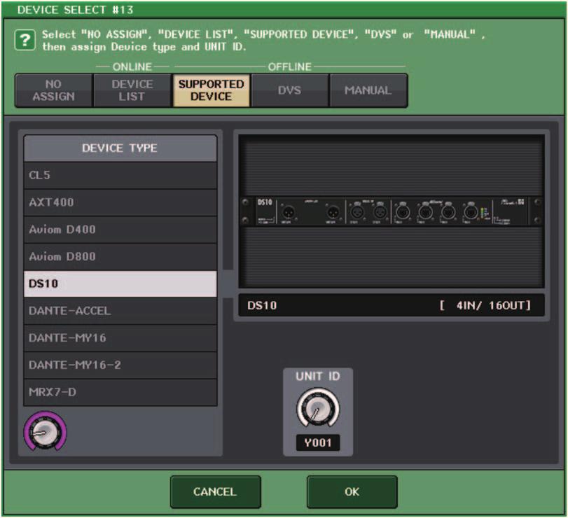
18 Setup I/O DEVICE window (I/O page) RSio64-D display If the card s internal sampling rate converter function is enabled when an MY8-AE96S mini- YGDAI card is inserted into the RSio64-D, the display will appear as shown below. 1 2 Setup Added supported devices The following devices are now supported: Audinate Dante-MY16-AUD2; d&b audiotechnik DS10; Shure AXT400, QLXD4, and ULXD4. They can be mounted on the DEVICE MOUNT page in the DANTE SETUP window. ShureAXT400, QLXD4, and ULXD4 can be mounted only when online. 1 Card name AE96S (w/src) is displayed. If the card s internal sampling rate converter function is disabled, MY8-AE96S is displayed. 2 WCLK display CARD is displayed. If the card s internal sampling rate converter function is disabled, SLOT is displayed. 18

19 Setup 19

 PREFERRED MASTER When Dante Device Lock is enabled on a CL/QL console, the DANTE DEVICE LOCKED indicator lights up in red on the top left side of the DANTE")


20 Setup Dante Device Lock The CL/QL console and R series now support Dante Device Lock. Its status is displayed on CL/QL. Dante Device Lock prevents changes to the Dante audio network settings of a Dante device by another computer on the same network. Dante Device Lock settings are configured in Dante Controller. When Dante Device Lock is enabled on a CL/QL console, the following parameters cannot be changed. CONSOLE ID SECONDARY PORT BIT LATENCY (ms) PREFERRED MASTER When Dante Device Lock is enabled on a CL/QL console, the DANTE DEVICE LOCKED indicator lights up in red on the top left side of the DANTE SETUP window. If a device connected to the console is online, and Dante Device Lock is enabled for that device, the LOCKED indicator will appear in each window as shown below. If you try to change any of these parameters, the following message will appear at the bottom of the window. If Dante Device Lock is enabled for the console, the following specifications will apply. The master clock select buttons in the WORD CLOCK/SLOT window cannot be changed. None of the parameters in the DANTE INPUT PATCH window can be changed. RECALL and AUTO SETUP in the DANTE INPUT PATCH LIBRARY window will be disabled. None of the parameters in the I/O DEVICE [OUTPUT PATCH] window can be changed. If a file is being loaded from USB memory to a device that has Dante Device Lock enabled, the settings will not be changed by the loaded file. A message is displayed on the screen. If the console s internal memory is initialized to the factory settings, Dante Device Lock will remain enabled and cannot be changed. Locked parameters will also not be initialized. Refer to the Initializing the unit to factory default settings on CL or QL series s Reference Manual. If the console s Dante settings are initialized to the factory settings, Dante Device Lock will be disabled. Locked parameters will also be initialized. Refer to the Initializing the console settings and Dante audio network settings on CL or QL series s Reference Manual. USB memory cannot be used to update the Dante module firmware. In addition, Dante Firmware Update Manager will not update the firmware. If Dante Device Lock is enabled for a remote device, all offline settings (such as Dante Patch) for the device will be disabled. Even if Dante Device Lock is enabled for an I/O device, remote control that is unrelated to Dante settings (such as HA control for R series) is possible. 20
 Use this window to set the console s IP address, in order to use the Dante PRIMARY connector on the rear panel to remote-control external devices.")


21 Setup Added functions in the NETWORK window If you select DHCP or AUTO IP, the window will appear as shown below and you will be unable to set the IP ADDRESS, SUBNET MASK, and GATE WAY ADDRESS. NETWORK window (FOR DEVICE CONTROL page) Use this window to set the console s IP address, in order to use the Dante PRIMARY connector on the rear panel to remote-control external devices. DHCP, AUTO IP, and fixed IP settings are supported. Even on DHCP networks, it is now possible to remotely control external devices such as Tio1608-D and Shure s ULDX APPLY button Press this button after you have changed the IP address settings. When the ATTENTION window appears, press the OK button and then turn the console off and back on again. 2 1 CURRENT IP SETTING field This field shows the current setting. NEXT IP SETTING field Tabs Use these tabs to select a group of items to view (FOR MIXER CONTROL or FOR DEVICE CONTROL). If you use the IP SETTING MODE select buttons to select DHCP or AUTO IP, it may take some time for the IP address to be configured. During this time, the window will appear as shown below. 2 IP SETTING MODE select buttons Use these buttons to select how to set the IP address the next time the console is turned on. Select DHCP, AUTO IP, or STATIC IP. If you select AUTO IP, the Dante network automatically sets the console s IP address to xxx.xxx. 21

 However, this message will take priority over the SECONDARY connection.")
.")
22 Setup NETWORK window (FOR MIXER CONTROL page) Use this window to set the console s IP address, in order to use the NETWORK connector on the rear panel to remote-control the console from CL Editor/QL Editor, StageMix, or the MonitorMix application. Set the UNIT Name and PIN for the MonitorMix application here. For the IP SETTING MODE select buttons, only STATIC IP button is enabled. The other buttons cannot be selected. Alert message display If the Dante network is not connecting at gigabit speeds, a message is now displayed at the bottom of the LCD. Example message: 1 When the PRIMARY connection is active but not working at gigabit speeds: *) However, this message will take priority over the SECONDARY connection. 2 When the PRIMARY connection is not active, and when the SECONDARY connection is active but not working at gigabit speeds: 3 When the PRIMARY connection is active and working at gigabit speeds, but the SECONDARY connection is not working at gigabit speeds: Set whether to turn the alert messages on or off in the ERROR MESSAGE field in the USER SETUP window (PREFERENCE page). 1 1 DANTE ALERT If this is on, an alert message will appear at the bottom of the LCD when the Dante network is not connecting at gigabit speeds. If this alert message is displayed, check the following items: Switch settings Is the console connected to a switch that does not function at a speed of 1000Mbps? Are you using a cable that does not support 1000BASE-T? Dante audio network settings Added error messages [SYSTEM] indicators Meaning Possible solution Lit Lit You changed the positions of the device setting DIP switches or rotary switch, or changed the Dante settings from Dante Controller. Therefore, the positions of the device setting DIP switches do not match the actual Dante settings. If the Device Lock setting was enabled from Dante Controller, disable the setting, or check the device setting DIP switch positions, and set them to accommodate the current situation. 22

23 CL/QL Editor CL/QL Editor Reading and Writing CSV files Added option for writing CSV files You can now set an output format before selecting a folder for writing CSV files. Added specifications for the CSV file read function The number of synonyms and abbreviations that can be used when creating a CSV file have been increased. Channel color notation Original notation Blue BL, B Notation when reading a CSV file Orange Yellow Purple Cyan OR, O YE, YL, Y PU, P SkyBlue, CY, C Short format: CL/QL Editor V4.0.0 and V4.0.1 file format Normal format: CL/QL Editor V4.1 file format In V4.1, CSV files can be read in both Short format and Normal format. If you select the [Export Comments of Detailed Form] check box, data that is not omitted from the comment line (line 3) is added and output to the CSV file. Magenta Red Green Off Pink, PK, M, MG Brown, RD, BN, R GN, G This notation is not case sensitive. Black, BK, (Treated as Off if there is no notation.) 23
24 Reading and Writing CSV files Channel icon notation Original notation Notation when reading a CSV file Original notation Notation when reading a CSV file Wireless WirelessMic, W/L, W.L Kick BassDrum, B.Dr, BD, B.D Podium Speech, Lecture Snare Sn, S.Dr, Botm, Botom Wedge Foot, Flor, Floor Hi-Hat HiHat, HH 2way Tom RackTom, F.Tom, Ftom, LTom, HTom In-Ear InEar, IEM, Ear Drumkit Drum, Kit, Drums, Top, TopL, TopR, O.HEAD, O.H Effector Fx, Eff, Effect Perc. Percussion, Per, Cong, conga, Bong, Bongo Media1 CD, MD, DISC A.Bass AcousticBass, Bass, C.Bass, CB, C.B, AB, A.B, Vc Media2 PB Strings String, Str, Vl, Vn, Vla Video VTR, DVD, Blu E.Bass ElectricBass, E.B, EB Mixer Mix A.Guitar A.Gt, AcousticGuitar, AcousticGt, A.G, AG PC DAW E.Guitar E.Gt, ElectricGuitar, ElectricGt, E.G, EG Processor DME, DSP, DLY, DELAY, REV, Reverb BassAmp B.Amp, B.A Audience Aud GuitarAmp GtAmp, G.Amp, G.A Star1 Trumpet TP, Trp Star2 Trombone Tb, Trb Blank (Treated as Blank if there is no notation.) Saxophone Piano Organ Keyboard Male Female Choir Dynamic Condenser Sax, SSax, ASax, TSax, BSax Pf, AP, PfL, PfR, PfH Org, Leslie KB, Key, KeyL, KeyR, EP, E.Pf, Syn, EPL, EPR, SynL, SynR Chorus, Cho, Chor DynamicMic CondenserMic This notation is not case sensitive. Spaces within the notation are not recognized. 24
25 Reading and Writing CSV files Port name notation for input patches and output patches Original notation (Normal format) Original notation (Short format) NONE NONE None DANTE [n] DNT [n] Dante [n] Additional notation when reading a CSV file * Underlined words can be omitted. * [n] indicates a number (such as a channel number). Original notation (Normal format) Original notation (Short format) MONITOR L MON L Monitor Left MONITOR R MON R Monitor Right MONITOR C MON C Monitor Center Additional notation when reading a CSV file * Underlined words can be omitted. * [n] indicates a number (such as a channel number). OMNI [n] OMNI [n] Omni [n] AD [n] CUE L CUE L Cue A Cue Left INPUT [n] INPUT [n] Input [n] PB L PBL Playback Output Left PB R PBR Playback Output Right SLOT1 [n] SL1 [n] Slot1 [n] SLOT2 [n] SL2 [n] Slot2 [n] SLOT3 [n] SL3 [n] Slot3 [n] FX [n] A FX[n]A Effect Rack [n] A FX [n] B FX[n]B Effect Rack [n] B PRFX [n] A PR[n]A Premium Rack [n] A PRFX [n] B PR[n]B Premium Rack [n] B GEQ [n] A GEQ[n]A GEQ Rack [n] A GEQ [n] B GEQ[n]B GEQ Rack [n] B MIX [n] MX [n] Mix Channel [n] MATRIX [n] MT [n] Matrix Channel [n] CUE R CUE R Cue Right CUE B L CUE BL Cue B Left CUE B R CUE BR Cue B Right INS CH [n] IC [n] Insert1 Input Channel [n] INS MIX [n] IM [n] Insert1 Mix Channel [n] INS MATRIX [n] IMT [n] Insert1 Matrix Channel [n] INS STEREO L ISTL Insert1 Stereo Output Left INS STEREO R ISTR Insert1 Stereo Output Right INS MONO (C) IMONO Insert1 Mono (C) DIR CH [n] DI [n] Direct Input Channel CAS MIX [n] CMX [n] Cascade Mix [n] CAS MARIX [n] CMT [n] Cascade Matrix [n] CAS STEREO L CSTL Cascade Stereo Left CAS STEREO R CSTR Cascade Stereo Right STEREO L STEREO R STL STR Stereo Output Left Main L Stereo Output Right Main R CAS MONO (C) CMONO Cascade Mono (C) CAS CUE L CCUE L Cascade Cue Left CAS CUE R CCUE R Cascade Cue Right MONO (C) MONO Mono (C) STEREO L+C STLC Stereo Output L+C CAS CUE B L CCUE BL Cascade Cue B Left CAS CUE B R CCUE BR Cascade Cue B Right STEREO R+C STRC Stereo Output R+C 25
.")
26 Support for devices that do not feature Dante output Original notation (Normal format) Original notation (Short format) Additional notation when reading a CSV file * Underlined words can be omitted. * [n] indicates a number (such as a channel number). Support for devices that do not feature Dante output INS2 CH [n] INS2 MIX [n] IC2 [n] IM2 [n] Insert2 Input Channel [n] Ins2 Input Channel [n] Insert2 Mix Channel [n] Ins2 Mix Channel [n] Devices that do not feature Dante output, such as Shure AXT400, QLXD4, and ULXD4, can now be controlled. Selected Channel window (input channels) INS2 MATRIX [n] IMT2 [n] Insert2 Matrix Channel [n] Ins2 Matrix Channel [n] The HA display appears as shown below. INS2 STEREO L ISTL2 Insert2 Stereo Output Left Ins2 Stereo Output Left AXT400 display When the receiver is on and connected via a ShowLink remote control INS2 STEREO R ISTR2 Insert2 Stereo Output Right Ins2 Stereo Output Right The RF level is shown for two channels (A and B). INS2 MONO (C) ISTMONO2 Insert2 Mono (C) SUR MONITOR L SMON L Surround Monitor Left TX.GAIN is displayed. SUR MONITOR R SMON R Surround Monitor Right SUR MONITOR C SMON C Surround Monitor Center SUR MONITOR LFE SMON LFE Surround Monitor LFE SUR MONITOR LS SMON LS Surround Monitor Ls When the receiver is on and not connected via a ShowLink remote control SUR MONITOR RS SMON RS Surround Monitor Rs MONITOR MATRIX L MMT L Monitor Matrix Left MONITOR MATRIX R MMT R Monitor Matrix Right MONITOR MATRIX C MMT C Monitor Matrix Center MONITOR MATRIX LFE MMT LFE Monitor Matrix LFE MONITOR MATRIX LS MMT LS Monitor Matrix Ls MONITOR MATRIX RS MMT RS Monitor Matrix Rs This notation is not case sensitive. This notation is recognized even if spaces are added between each word, or if the word order is changed. However, the notation will not be recognized if a space is added in the middle of a word. 26

 display has the")
27 Support for devices that do not feature Dante output When the receiver is off Overview window (INPUT CH window) The HA display appears as shown below. AXT400 display When the receiver is on and connected via a ShowLink remote control The RF level is shown for two channels (A and B). When the receiver is on and not connected via a ShowLink remote control QLXD4 and ULXD4 display The RF channel (A or B) display has the same design as for the AXT400. QLXD4 and ULXD4 display The RF channel (A or B) display has the same design as for the AXT
28 Yamaha Pro Audio global website Yamaha Downloads Manual Development Group 2016 Yamaha Corporation Published 12/2016 MA-A0
Reference Manual. How to Use This Reference Manual
 How to Use This The CL5/CL3/CL1 (this document) allows you to search for terms and take advantage of links in the text. Searching for terms To search for a term, use the search function of the software
Reference Manual. How to Use This Reference Manual
 How to Use This The QL5/QL1 (this document) allows you to search for terms and take advantage of links in the text. Searching for terms To search for a term, use the search function of the software you're
CONTENTS Page 1.0 System Requirements Wi-Fi Settings Getting Started Mixer Window... 14
 Welcome: Thank you for downloading the CL StageMix ipad app for the Yamaha CL series digital mixing consoles. The latest firmware version for CL series can be downloaded from https://www.yamaha.com/proaudio/
QL StageMix V8 User Guide
 Welcome: Thank you for downloading the QL StageMix ipad app for the Yamaha QL series digital mixing consoles. The latest firmware version for QL series can be downloaded from http://www.yamahaproaudio.com/
Reference Manual. How to Use This Reference Manual
 How to Use This The QL5/QL1 (this document) allows you to search for terms and take advantage of links in the text. Searching for terms To search for a term, use the search function of the software you're
DIGITAL MIXING CONSOLE. TF Editor V3.6 User's Guide
 DIGITAL MIXING CONSOLE TF Editor V3.6 User's Guide EN Special notices Copyrights of the software and this document are the exclusive property of Yamaha Corporation. Copying or modifying the software or
CL StageMix V6 User Guide
 Welcome: Thank you for downloading the CL StageMix ipad app for the Yamaha CL series digital mixing consoles. The latest firmware version for CL series can be downloaded from www.yamahaproaudio.com StageMix
TF5 / TF3 / TF1 DIGITAL MIXING CONSOLE. TF StageMix User's Guide
 TF5 / TF3 / TF1 DIGITAL MIXING CONSOLE EN Note The software and this document are the exclusive copyrights of Yamaha Corporation. Copying or modifying the software or reproduction of this document, by
SIGNAL PROCESSOR. Operation Manual
 SIGNAL PROCESSOR Operation Manual Using the PDF manual From the Contents on page 2, click on the desired topic to automatically jump to the corresponding page. Click on a link in this manual to jump to
LS9 StageMix V6 User Guide
 Welcome: Thank you for downloading the LS9 StageMix ipad app for the Yamaha LS9 digital mixing consoles. The latest firmware version for LS9 can be downloaded from www.yamahaproaudio.com StageMix is an
SIGNAL PROCESSOR. Operation Manual
 SIGNAL PROCESSOR Operation Manual Using the PDF manual From the Contents on page 2, click on the desired topic to automatically jump to the corresponding page. Click on a link in this manual to jump to
Console File Converter User Guide
 Console File Converter User Guide Rev.4.0 Special Notices The software and this user guide are the exclusive copyrights of Yamaha Corporation. Copying of the software or reproduction of this user guide
Using the oscillator
 Using the oscillator Here s how to send a sine wave or pink noise from the internal oscillator to a desired bus. In the function access area, press the MON- ITOR button to access the MONITOR screen. In
TF5 / TF3 / TF1 DIGITAL MIXING CONSOLE. TF Editor User Guide
 TF5 / TF3 / TF1 DIGITAL MIXING CONSOLE EN Special notices Copyrights of the software and this document are the exclusive property of Yamaha Corporation. Copying or modifying the software or reproduction
V1.7 Supplementary Manual
 This supplementary manual explains mainly the functions that have been added or changed in CL5/CL3/CL1 firmware V1.6 and V1.7. Use it in conjunction with the CL5/CL3/CL1 Owner s Manual and Reference Manual.
CL Editor. Special Notices. Contents. Owner s Manual. Yamaha Pro Audio Global Site
 CL Editor Owner s Manual Special Notices The software and this owner s manual are the exclusive copyrights of Yamaha Corporation. Copying of the software or reproduction of this manual in whole or in part
D-901 PC SOFTWARE Version 3
 INSTRUCTION MANUAL D-901 PC SOFTWARE Version 3 Please follow the instructions in this manual to obtain the optimum results from this unit. We also recommend that you keep this manual handy for future reference.
ULN-8 Quick Start Guide
 Metric Halo $Revision: 1671 $ Publication date $Date: 2012-7-21 12:42:12-0400 (Mon, 21 Jul 2012) $ Copyright 2012 Metric Halo Table of Contents 1.... 5 Prepare the unit for use... 5 Connect the ULN-8 to
User Guide. MonitorMix User Guide 1
 User Guide EN MonitorMix User Guide 1 Introduction Thank you for downloading MonitorMix app for ios or Android. With MonitorMix, you can control MIX/MATRIX/AUX mixes wirelessly for your CL, QL or TF series
M7CL V3 Editor. Version 3.5. Contents. Special Notices. Owner s Manual. Yamaha Pro Audio Global Site
 M7CL V3 Editor Version 3.5 Owner s Manual Special Notices The software and this owner s manual are the exclusive copyrights of Yamaha Corporation. Copying of the software or reproduction of this manual
USO RESTRITO. Quick Start Guide A guide for people using M7CL Version 3 in the real world.
 Quick Start Guide A guide for people using M7CL Version 3 in the real world. Part 1 An introductory guide to the M7CL group of consoles including features included in Version 3 Firmware and the M7CL-48ES
AxumVideo 0 intro. Now that you have connected the different AXUM system parts, you are ready to configure the system according to your own needs.
 AxumVideo 0 intro Now that you have connected the different AXUM system parts, you are ready to configure the system according to your own needs. On the left we see the RACK unit and on the right we see
TASCAM DM-24. The DM-24 Basics. TEAC Professional Division. Digital Mixing console
 TASCAM TEAC Professional Division DM-24 Digital Mixing console The DM-24 Basics DM-24 SIGNAL FLOW... 3 INPUTS... 3 RETURNS... 3 OPTIONS... 4 OUTPUTS... 5 AUX SENDS... 5 TRACKING OPTIONS... 5 Using AUX
SCM820 Digital IntelliMix Automatic Mixer SEAMLESS MIXING. ADVANCED CONTROL.
 SCM820 Digital IntelliMix Automatic Mixer SEAMLESS MIXING. ADVANCED CONTROL. SCM820 Digital IntelliMix Automatic Mixer The SCM820 is the flagship Shure digital automatic mixer for seamless, natural-sounding
LIO-8 Quick Start Guide
 Metric Halo $Revision: 1051 $ Publication date $Date: 2011-08-08 12:42:12-0400 (Mon, 08 Jun 2011) $ Copyright 2010 Metric Halo Table of Contents 1.... 5 Prepare the unit for use... 5 Connect the LIO-8
Screen Reference Guide
 DIGITAL MIXING SYSTEM Screen Reference Guide For GLD firmware Version V1.4 Check the Allen & Heath web site for the latest version available Also read the GLD User Guide AP8561 1. Contents 1. Contents...
Chapter 4 Signal Paths
 Chapter 4 Signal Paths The OXF-R3 system can be used to build a wide variety of signal paths with maximum flexibility from a basic default configuration. Creating configurations is simple. Signal paths
The 01X Configuration Guide
 The 01X Configuration Guide A Very Brief Introduction Welcome to the world of learning! Like many of you, I have spent countless hours reading and re-reading the 01x and the Cubase SX owner's manuals,
User Manual K.M.E. Dante Module
 User Manual K.M.E. Dante Module Index 1. General Information regarding the K.M.E. Dante Module... 1 1.1 Stream Processing... 1 1.2 Recommended Setup Method... 1 1.3 Hints about Switches in a Dante network...
FAQ. Mixing Features Phoenixville Pike, Suite 201 West Chester, PA Voice: Fax:
 Mixing Features How many channels is the A320? The A320 can mix up to 16 mono or stereo sources, and each channel button can host either a mono or stereo source. On the A-16II, a stereo source uses up
M7CL Editor. Contents. Special Notices. Owner s Manual. Yamaha Pro Audio Global Site
 M7CL Editor Owner s Manual Special Notices The software and this owner s manual are the exclusive copyrights of Yamaha Corporation. Copying of the software or reproduction of this manual in whole or in
USB AUDIO INTERFACE I T
 USB AUDIO INTERFACE EN DE FR ES IT JA Contents Introduction...3 Contents in this Operation Manual... 3 Features... 3 Panel Controls and Terminals (Details)...4 Rear Panel... 4 Front Panel... 6 Panel Controls
Wireless Studio. User s Guide Version 5.1x Before using this software, please read this manual thoroughly and retain it for future reference.
 4-743-161-12 (1) Wireless Studio User s Guide Version 5.1x Before using this software, please read this manual thoroughly and retain it for future reference. DWR-R01D/R02D/R02DN/R03D 2018 Sony Corporation
RELEASE NOTES. Introduction. Supported Devices. Mackie Master Fader App V4.5.1 October 2016
 RELEASE NOTES Mackie Master Fader App V4.5.1 October 2016 Introduction These release notes describe changes and upgrades to the Mackie Master Fader app and DL Series mixer firmware since Version 4.5. New
USER GUIDE TO THE ARENA OPERATION
 USER GUIDE TO THE ARENA OPERATION The mean of this guide is to help as a a quick reference guide to the operation of the most common functions of the ARENA console. It is not a substitute of the operation
2
 328 328 USER GUIDE NB Before you go any further, please read this first page as it will tell you all you need to know about starting off with the Spirit Digital 328 From all of us to you Thank you for
MP212 Principles of Audio Technology II
 MP212 Principles of Audio Technology II L a b # 1 D M 2000 Version 2.1, 02/22/11 revised AR. Older versions by JL and JMC Version 7, 09/11/13 revised AR Copyright 2007 Berklee College of Music. All rights
!! 1 of! 21. Magico Subwoofer Setup and DSP Control Manual. Password: Fact_ory
 Magico Subwoofer Setup and DSP Control Manual Password: Fact_ory Thank you for the purchase of your new Magico S-Sub or Q-Sub. The goal of this setup manual is to first integrate the subwoofer into your
CLA MixHub. User Guide
 CLA MixHub User Guide Contents Introduction... 3 Components... 4 Views... 4 Channel View... 5 Bucket View... 6 Quick Start... 7 Interface... 9 Channel View Layout..... 9 Bucket View Layout... 10 Using
Quick Start Guide. Soundcraft Si Series Quick Start Guide Issue 1010
 Quick Start Guide Soundcraft Si Series Quick Start Guide Issue 1010 Page 1 INTRODUCTION IMPORTANT Please read this manual carefully before using your mixer for the first time. Firstly, thanks for choosing
V4.7 Software Quick Start Guide
 V4.7 Software Quick Start Guide INTRODUCTION TO V4.7 The 4.7 software update for the Vi Series includes a major update to the functionality of the Vi4 console in particular, bringing a new level of power
y AW4416 Audio Workstation Signal Flow Tutorial
 y AW44 Audio Workstation Signal Flow Tutorial This tutorial will help you learn the various parts of a CHANNEL by following the signal through #1. Use the Signal Flow Diagram included with this document.
Setting up the Personal Mixing System
 Setting up the Personal Mixing System This document describes the basic setup procedures and signal flow for the Roland Personal Mixing (PM) System. It includes "How-to" information when using the PM system
HEDD Bridge B1 - Dante
 Heinz Electrodynamic Designs HEDD Bridge B1 - Dante User Manual EN Introduction HEDD s modular input card system, which we call the HEDD Bridge, brings versatile digital input connectivity including Dante
DNT0212 Network Processor
 DNT0212 Network Processor TECHNICAL DATA 32 inputs from Dante TM receive channels 2 analog line level inputs 16 outputs to Dante TM transmit channels 8 line level analog outputs 4 mic/line level analog
StudioLive RM32AI RM16AI Applications Guide
 StudioLive RM32AI RM16AI Applications Guide 1. General Control and Recording Control for RM mixers can be done via Firewire or Network connection. Network control requires connecting the mixers to the
SRP-V200. Audio Mixer
 Audio Mixer SRPV00 The versatile Sony SRPV00. Six stereo inputs, four mono inputs, four mixing buses and a full range of operational features combined in a single, compact unit. Use the parallel control
C8000. switch over & ducking
 features Automatic or manual Switch Over or Fail Over in case of input level loss. Ducking of a main stereo or surround sound signal by a line level microphone or by a pre recorded announcement / ad input.
System Interface Unit SIU-100/100T
 System Interface Unit /100T Since its introduction, the Digital Mixer has opened up an entirely new set of opportunities for affordable PA and sound-recording applications. Recognizing the ever-increasing
USER S GUIDE ADX 100. Frequency Conscious Gating, Compression, Limiting, and Expansion. Plug-in for Mackie Digital Mixers
 USER S GUIDE ADX 100 Frequency Conscious Gating, Compression, Limiting, and Expansion TM Plug-in for Mackie Digital Mixers Iconography This icon identifies a description of how to perform an action with
Model 7600 HD/SD Embedder/ Disembedder Data Pack
 Model 7600 HD/SD Embedder/ Disembedder Data Pack E NSEMBLE D E S I G N S Revision 2.1 SW v2.0.1 This data pack provides detailed installation, configuration and operation information for the 7600 HD/SD
DNT0212 Network Processor
 DNT0212 Network Processor TECHNICAL DATA 32 inputs from Dante TM receive channels 2 analog line level inputs 16 outputs to Dante TM transmit channels 8 line level analog outputs 4 mic/line level analog
IP LIVE PRODUCTION UNIT NXL-IP55
 IP LIVE PRODUCTION UNIT NXL-IP55 OPERATION MANUAL 1st Edition (Revised 2) [English] Table of Contents Overview...3 Features... 3 Transmittable Signals... 3 Supported Networks... 3 System Configuration
FS1-X. Quick Start Guide. Overview. Frame Rate Conversion Option. Two Video Processors. Two Operating Modes
 FS1-X Quick Start Guide Overview Matching up and synchronizing disparate video and audio formats is a critical part of any broadcast, mobile or post-production environment. Within its compact 1RU chassis,
SOUND TECH RIDER FIDO
 SOUND TECH RIDER FIDO Tech advancing conctact for FIDO is mr. dave muscheidt 0041788745005/muscheid@tiscali.ch 1. SOUND IN GENERAL After receiving this rider please ask your tech coordinator/production
M-16DX 16-Channel Digital Mixer
 M-6DX 6-Channel Digital Mixer Workshop Getting Started with the M-6DX 007 Roland Corporation U.S. All rights reserved. No part of this publication may be reproduced in any form without the written permission
CLOCKAUDIO. MR88 Automatic Microphone Mixer. Version 4.2
 CLOCKAUDIO MR88 Automatic Microphone Mixer Version 4.2 Clockaudio Limited,22 Arnside Road WATERLOOVILLE Hampshire. UK Tel : +44 (0)2392 251193 Fax : +44 (0)2392 251201 Email : sales@clockaudio.co.uk CONTENTS
Syrah. Flux All 1rights reserved
 Flux 2009. All 1rights reserved - The Creative adaptive-dynamics processor Thank you for using. We hope that you will get good use of the information found in this manual, and to help you getting acquainted
X-Panda User s Guide
 X-Panda User s Guide This documentation is intended to be read along side the X-Panda Installation Guide which is available for download from our website www.solidstatelogic.com 82BXEM01A Contents Introduction
LPFM LOW POWER FM EQUIPMENT GUIDE
 LPFM LOW POWER FM EQUIPMENT GUIDE BROADCAST AUDIO PERFECTIONISTS LPFM low power FM equipment guide One of the challenges in launching a new LPFM station is assembling a package of equipment that provides
C8188 C8000 1/10. digital audio modular processing system. 4 Channel AES/EBU I/O. features. block diagram. 4 balanced AES inputs
 features 4 balanced AES inputs Input Sample Rate Converters (SRC) 4 balanced AES outputs Relay bypass for pairs of I/Os Relay wait time after power up Master mode (clock master for the frame) 25pin Sub-D,
Setup Utility Guide. SF-16M 16-Channel Digital Matrix Amplifier
 Setup Utility Guide SF-16M 16-Channel Digital Matrix Amplifier Advanced Configuration Using the Setup Utility The Setup Utility is the most efficient way to set up SF-16M advanced features (using *Mac
Features/Specifications
 Introduction Thank you for purchasing the DD Audio DSI-1(Digital Signal Integrator). The DSI-1 is a feature rich audio signal processor that will allow you to precisely tune the acoustics of your car audio
DIVERSITY DVB-T RECEIVER (DDR)
") User s Manual The most important thing we build is trust. DIVERSITY DVB-T RECEIVER (DDR) Cobham Surveillance GMS Products 1916 Palomar Oaks Way Ste 100 Carlsbad, CA 92008 100-M0062X2 T: 760-496-0055 05/15/09
User s Manual The most important thing we build is trust. DIVERSITY DVB-T RECEIVER (DDR) Cobham Surveillance GMS Products 1916 Palomar Oaks Way Ste 100 Carlsbad, CA 92008 100-M0062X2 T: 760-496-0055 05/15/09
CHAPTER 3 AUDIO MIXER DIGITAL AUDIO PRODUCTION [IP3038PA]
![CHAPTER 3 AUDIO MIXER DIGITAL AUDIO PRODUCTION [IP3038PA]](/thumbs/73/68858919.jpg "CHAPTER 3 AUDIO MIXER DIGITAL AUDIO PRODUCTION [IP3038PA]") CHAPTER 3 AUDIO MIXER DIGITAL AUDIO PRODUCTION [IP3038PA] Learning Objectives By the end of this chapter, students should be able to: 1 State the function of the audio mixer in the sound studio. 2 Explain
CHAPTER 3 AUDIO MIXER DIGITAL AUDIO PRODUCTION [IP3038PA] Learning Objectives By the end of this chapter, students should be able to: 1 State the function of the audio mixer in the sound studio. 2 Explain
C ch optical MADI & AoIP I/O. MASTER mode: A C8000 frame may be clocked via MADI input or AES67 network. AoIP Dante Brooklin II OEM module
 features Interface for AoIP (AES67 or DANTE) Two AoIP network ports for redundant or switch operation MADI I/O connection Optical SFP module / LC connectors (multi mode or single mode fiber) BNC parallel
CCE900-IP-TR. User s Guide
 CCE900-IP-TR CCE900-IP-T & CCE900-IP-R User s Guide i-tech Company LLC TOLL FREE: (888) 483-2418 EMAIL: info@itechlcd.com WEB: www.itechlcd.com 1. Introduction The CCE900-IP-T & CCE900-IP-R is a solution
Quick Start for TrueRTA (v3.5) on Windows XP (and earlier)
 on Windows XP (and earlier)") Skip directly to the section that covers your version of Windows (XP and earlier, Vista or Windows 7) Quick Start for TrueRTA (v3.5) on Windows XP (and earlier) Here are step-by-step instructions to get
Skip directly to the section that covers your version of Windows (XP and earlier, Vista or Windows 7) Quick Start for TrueRTA (v3.5) on Windows XP (and earlier) Here are step-by-step instructions to get
Using Cubase SE with DSP Factory
 Manual by Ludvig Carlson, Anders Nordmark, Roger Wiklander Quality Control: C. Bachmann, H. Bischoff, S. Pfeifer, C. Schomburg The information in this document is subject to change without notice and does
EdgeConnect Module Quick Start Guide ITERIS INNOVATION FOR BETTER MOBILITY
 EdgeConnect Module Quick Start Guide ITERIS INNOVATION FOR BETTER MOBILITY 493456301 Rev B April 2009 Table of Contents Installation... 1 Setup... 2 Operation... 4 Live Video... 4 Video Settings... 5 Network
RT-DRIVE DLM808 DIGITAL PROCESSOR AUDIO MATRIX PROCESSOR
 RT-DRIVE DLM808 DIGITAL PROCESSOR AUDIO MATRIX PROCESSOR 2 1. Introduction 2. Features 3. Usefull Data 4. Function Buttons and LED Indicators 5. Rear Panel 6. DSP Control 1. Configuration of IP Address
FS3. Quick Start Guide. Overview. FS3 Control
 FS3 Quick Start Guide Overview The new FS3 combines AJA's industry-proven frame synchronization with high-quality 4K up-conversion technology to seamlessly integrate SD and HD signals into 4K workflows.
Element 78 MPE-200. by Summit Audio. Guide To Operations. for software version 1.23
 Element 78 MPE-200 by Summit Audio Guide To Operations for software version 1.23 TABLE OF CONTENTS IMPORTANT SAFETY AND GROUNDING INSTRUCTIONS COVER 1. UNPACKING AND CONNECTING...3 AUDIO CONNECTIONS...4
On the Move. Digital Mixers
 ipad*/tablet controlled 18-input, 12-bus digital mixer for studio and live application 16 award-winning MIDAS-designed, fully programmable mic preamps for audiophile sound quality Integrated Wifi module
DriveRack VENU360 DriveRack VENU360-B DriveRack VENU360-D Owner s Manual
 DriveRack VENU60 DriveRack VENU60-B DriveRack VENU60-D Owner s Manual Warranty 1. Please register your product online at dbxpro.com. Proof-of-purchase is considered to be the responsibility of the consumer.
Get Funked Compact 6-piece. Technical Rider 2017/18. Contents Page 1/2 Technical Rider Page 3 Channel List Page 4 Monitor List Page 5 Stage Diagram
 Get Funked Compact 6-piece Technical Rider 2017/18 Contents Page 1/2 Technical Rider Page 3 Channel List Page 4 Monitor List Page 5 Stage Diagram Contact Martyn Strange Tour Manager UK cell phone: +44
C8491 C8000 1/17. digital audio modular processing system. 3G/HD/SD-SDI DSP 4/8/16 audio channels. features. block diagram
 features 4 / 8 / 16 channel LevelMagic2 SDI-DSP with level or loudness (ITU-BS.1770-1/ ITU-BS.1770-2, EBU R128) control 16 channel 3G/HD/SD-SDI de-embedder 16 in 16 de-embedder matrix 16 channel 3G/HD/SD-SDI
HORACE X PERFORMANCE REQUIREMENTS (Technical)
") 1 HORACE X PERFORMANCE REQUIREMENTS (Technical) PA System: Minimum Requirement: Horace X need a professional, clean, full-range P.A. Sound System designed for live Rock groups, with a suitable power rating
1 HORACE X PERFORMANCE REQUIREMENTS (Technical) PA System: Minimum Requirement: Horace X need a professional, clean, full-range P.A. Sound System designed for live Rock groups, with a suitable power rating
OPERATION MANUAL. USF-1013DEMUX Digital Audio Demultiplexer. 2 nd Edition. Software Version Higher
 OPERATION MANUAL USF-1013DEMUX Digital Audio Demultiplexer 2 nd Edition Software Version 2.00 - Higher Precautions Important Safety Warnings [Power] Stop [Circuitry Access] Do not place or drop heavy or
OPERATING INSTRUCTIONS
 OPERATING INSTRUCTIONS MATRIX SYSTEM SX-2000 SERIES Thank you for purchasing TOA's Matrix System. Please carefully follow the instructions in this manual to ensure long, trouble-free use of your equipment.
CVP-609 / CVP-605. Reference Manual
 CVP-609 / CVP-605 Reference Manual This manual explains about the functions called up by touching each icon shown in the Menu display. Please read the Owner s Manual first for basic operations, before
D-2000 SERIES DIGITAL MIXING SYSTEM
 D-2000 SERIES DIGITAL MIXING SYSTEM Integrating high-performance mixing, matrixing and processing functions to meet a wide scope of sound reinforcement applications Expandable a operation, a system contr
LAVALLEY LAW LIBRARY MEDIA SERVICES INSTRUCTIONAL MEDIA OPERATIONS MANUAL
 LAVALLEY LAW LIBRARY MEDIA SERVICES INSTRUCTIONAL MEDIA OPERATIONS MANUAL OCTOBER 27, 2007 Page 1 of 29 TABLE OF CONTENTS TABLE OF CONTENTS 03 INTRODUCTON TO MEDIA SERVICES OPERATIONS 04 AUDITORIUM OPERATIONS
SR-D8-M, SR-D8-S. (Ver ) SOFTWARE INSTRUCTIONS
 SOFTWARE INSTRUCTIONS") SOFTWARE INSTRUCTIONS active l ine array speak er SYStems SR-D8-M, SR-D8-S (Ver. 1.1.1) Thank you for purchasing TOA's Active Line Array Speaker Systems. Please carefully follow the instructions in this
SOFTWARE INSTRUCTIONS active l ine array speak er SYStems SR-D8-M, SR-D8-S (Ver. 1.1.1) Thank you for purchasing TOA's Active Line Array Speaker Systems. Please carefully follow the instructions in this
Technical Datasheet. Overview. Qu-SB v1.9 Technical Datasheet 1 Allen & Heath Ltd
 Allen & Heath Limited Kernick Industrial Estate Penryn, Cornwall, TR10 9LU, UK www.allen-heath.com Technical Datasheet Overview Rack-mountable Digital Mixer for Live, Studio and Installation 16-32 Mono
Model CMX3838A2 AV Matrix Switch with DSP audio (firmware 1.0)
") Model CMX3838A2 AV Matrix Switch with DSP audio (firmware 1.0) Overview: This product is a full featured video & audio matrix switch. It is most commonly used to independently distribute video & audio
Model CMX3838A2 AV Matrix Switch with DSP audio (firmware 1.0) Overview: This product is a full featured video & audio matrix switch. It is most commonly used to independently distribute video & audio
1608-II and 2448 Recording Console Operator s Manual
 Recording Console Operator s Manual Written for Automated Processes ncorporated by Dan Pfeifer Rev. 18-12-30 2018 8301 Patuxent Range Road Jessup, MD 20794 USA 301-776-7879 http://www.apiaudio.com Table
IP LIVE PRODUCTION UNIT NXL-IP55 USO RESTRITO. OPERATION MANUAL 1st Edition (Revised 2) [English]
![IP LIVE PRODUCTION UNIT NXL-IP55 USO RESTRITO. OPERATION MANUAL 1st Edition (Revised 2) [English]](/thumbs/89/99059597.jpg "IP LIVE PRODUCTION UNIT NXL-IP55 USO RESTRITO. OPERATION MANUAL 1st Edition (Revised 2) [English]") IP LIVE PRODUCTIO UIT XL-IP55 USO RESTRITO OPERATIO MAUAL 1st Edition (Revised 2) [English] Table of Contents Overview... 3 Features... 3 Transmittable Signals... 3 Supported etworks... 3 System Configuration
IP LIVE PRODUCTIO UIT XL-IP55 USO RESTRITO OPERATIO MAUAL 1st Edition (Revised 2) [English] Table of Contents Overview... 3 Features... 3 Transmittable Signals... 3 Supported etworks... 3 System Configuration
Reference Guide 2014 ZOOM CORPORATION. Copying or reprinting this manual in part or in whole without permission is prohibited.
 Reference Guide 2014 ZOOM CORPORATION Copying or reprinting this manual in part or in whole without permission is prohibited. Introduction is a mixer application designed specifically for the. Using a
SREV1 Sampling Guide. An Introduction to Impulse-response Sampling with the SREV1 Sampling Reverberator
 An Introduction to Impulse-response Sampling with the SREV Sampling Reverberator Contents Introduction.............................. 2 What is Sound Field Sampling?.....................................
USER S GUIDE DSR-1 DE-ESSER. Plug-in for Mackie Digital Mixers
 USER S GUIDE DSR-1 DE-ESSER Plug-in for Mackie Digital Mixers Iconography This icon identifies a description of how to perform an action with the mouse. This icon identifies a description of how to perform
Nuendo 3 / DM1000 V2 Setup and Operation
 Nuendo 3 / DM1000 V2 Setup and Operation Page 1 Nuendo 3 / DM1000 V2 Setup and Operation This document describes setup and operation for remote control of Nuendo from the DM1000 digital mixing console.
NEWS239 SILVER C M Y BK 12/17 12/20 00/00 op :tobi
 D I G I T A L A U D I O M I X E R DMX-R100 2 D I G I T A L A U D I O M I X E R DMX-R100 The affordable, fully professional mixing console Sony's digital innovations are at the heart of a wide range of
StudioLive Series III
 www.presonus.com English Table of Contents 1 Overview 1 1.1 About AVB Networking 1 2 Getting Started 2 2.1 Channel Routing Grid 5 2.2 Preamp Control 6 2.3 Stagebox Modes 6 2.4 Recording in Stagebox Mode
DIGITAL SPEAKER MANAGEMENT UK
 DSM2-6mkII DIGITAL SPEAKER MANAGEMENT 170.659UK Features 96kHz sampling frequency, 32-bit A/D and D/A converter, 24-bit DSP processor Input channel: 6-band parametric EQ, Delay, Polarity Output channel:
Bringing large-scale, multi-format work within your reach
 Bringing large-scale, multi-format work within your reach Constellation-XT smashes through the price/performance boundaries for a fully integrated large scale digital recording, editing and mixing system.
Mackie Control and Cubase SX/SL
 Mackie Control and Cubase SX/SL - 1 - The information in this document is subject to change without notice and does not represent a commitment on the part of Steinberg Media Technologies AG. The software
WAVES H-EQ HYBRID EQUALIZER USER GUIDE
 WAVES H-EQ HYBRID EQUALIZER USER GUIDE TABLE OF CONTENTS CHAPTER 1 INTRODUCTION...3 1.1 WELCOME...3 1.2 PRODUCT OVERVIEW...3 1.3 CONCEPTS AND TERMINOLOGY...4 1.4 COMPONENTS...7 CHAPTER 2 QUICK START GUIDE...8
BELAR FMHD-1 PRECISION DIGITAL FM HD MONITOR/ANALYZER. Guide to Operations 2011/06/22
 BELAR FMHD-1 PRECISION DIGITAL FM HD MONITOR/ANALYZER Guide to Operations 2011/06/22 2011 BELAR ELECTRONICS LABORATORY, INC. 119 LANCASTER AVENUE P.O. BOX 76 DEVON, PA 19333-0076 USA VOICE (610) 687-5550
When going digital is this easy, why stay analogue?
 Soundcraft, Harman International Industries Ltd., Cranborne House, Cranborne Road, Potters Bar, Hertfordshire EN6 3JN, UK T: +44 (0)1707 665000 F: +44 (0)1707 660742 E: soundcraft.info@harmancom Soundcraft