USERS MANUAL HDA SERIES 8/16 CHANNEL.
|
|
|
- Jemima Parks
- 6 years ago
- Views:
Transcription


1 USERS MANUAL HDA SERIES 8/16 CHANNEL
2 Thank you for choosing Night Owl Security Products! By purchasing a Night Owl product, you receive a one (1) year warranty covering manufacturing defects in material and workmanship. Make the most of your warranty by completing the registration form online. In addition to warranty and technical support benefits, you will have access to our multitude of free instructional How to Videos. You can also view our instructional videos by clicking the How to Videos tab within your product s page on our website. Register at Night Owl s HDA Series Camera Compatibility: Night Owl s HD Analog DVRs are compatible with most analog cameras ( TVL), Night Owl s Analog HD (AHD), and HD Analog (HDA) cameras. If the camera s video quality either day or night is degraded, you may need to change the cable run from the camera to the DVR. This system is designed to work with 24 AWG cabling or better. Please see the warranty section of this manual for exclusions and additional details. Not all features and capabilities are shared across all models so you may see features which are not applicable. In addition you may see screen images that do not exactly match those on your display. This manual was accurate at the time it was completed. Due to our ongoing effort to constantly improve our products, functions may have been added or changed. Night Owl highly recommends installing the most current firmware version available for your system. Verify your firmware version (V ) on the Info screen of the System menu tab. Scan or click the QR codes below to access our instructional videos that can assist you in configuring your Night Owl Security system. DVR CONNECTIVITY STARTUP WIZARD MOBILE APP SETUP HDA Series Users Manual
3 TABLE OF CONTENTS Table of Contents 3
4 Table of Contents CHAPTER 1: FCC WARNINGS...7 CHAPTER 2: SAFETY INSTRUCTIONS...9 CHAPTER 3: SPECIFICATIONS System Requirements Package Contents DVR Diagram Camera Diagram Mouse and Remote Diagrams...15 CHAPTER 4: CAMERA INSTALLATION Video/Audio Power Standard Camera Power Integrated Battery Backup Camera Power Mounting the Cameras...20 CHAPTER 5: DVR INSTALLATION Connecting to a TV Power...24 CHAPTER 6: GETTING STARTED Startup Wizard Night Owl HD Mobile App Displays and Icons Login Screen Live View (All Channels) Live View (Single Channel) Menu Screen HDA Series Users Manual
5 CHAPTER 7: MENUS AND SETTINGS General Menu Display a. Output b. Privacy Zone SnapShot a. SnapShot b. SnapShot Schedule Network a. Main...38 b. Substream c d. Schedule e. DDNS Alarm a. Motion b. Setting Detection Area Cameras Menu Settings Record Menu (Playback) General (Playback) Events & Pictures (Playback & Backup Files) Settings (Record) a. Basic b. Record Schedule c. Mainstream Device Menu HDD PTZ System Menu General...49 a. Settings b. DST c. NTP Users Info Table of Contents 5
6 a. Info...52 b. Channel Info c. Record Info Log Advanced Menu Maintain Events Auto Upgrade...56 CHAPTER 8: REMOTE ACCESS System Requirements Setup Network Configuration Windows Operating System Mac Operating System Port Configuration DDNS Registration Adding the DDNS to Your DVR...66 CHAPTER 9: GLOSSARY...67 CHAPTER 10: WARRANTY...69 CHAPTER 11: TROUBLESHOOTING...72 CHAPTER 12: CUSTOMER SUPPORT...75 CHAPTER 13: USER INFORMATION...77 SUPPORT VIDEOS For your reference, we have created an instructional video that explains the menu structure and functionality of your Night Owl recorder in detail. Click on the icon at any time to view Night Owl s instructional videos at ADVANCED Night Owl s DVRs are manufactured for quality and ease of use. As such, our DVRs contain menus designed for advanced user s that should not be adjusted without having enhanced knowledge regarding the menu. In most cases the default settings allow for optimal functionality. The menus that should maintain the default settings are indicated with this icon. 6 HDA Series Users Manual
7 CHAPTER 1 FCC WARNINGS Chapter 1: FCC Warnings SUPPORT VIDEOS 7
8 Chapter 1: FCC Warnings FCC This equipment has been tested and found to comply within limits for Class B digital devices pursuant to Part 15 of Federal Communication Commission (FCC) rules. FCC Compliance Statement These limits are designed to provide reasonable protection against frequency interference in residential installation. This equipment generates, uses, and can radiate radio frequency energy, and if not installed or used accordance with the instructions, may cause harmful interference to radio communication. However, there is no guarantee that interference will not occur in television reception, which can be determined by turning the equipment off and on. The user is encouraged to try and correct the interference by one or more of the following measures: Reorient or relocate the receiving antenna. Increase the separation between the equipment and the receiver. Connect the equipment into an outlet on a circuit different from that to which the receiver is connected CAUTION The Federal Communications Commission warns the user that changes or modifications to the unit not expressly approved by the party responsible for compliance could void the user s authority to operate the equipment. 8 HDA Series Users Manual
9 CHAPTER 2 SAFETY INSTRUCTIONS Chapter 2: Safety Instructions SUPPORT VIDEOS 9
10 Chapter 2: Safety Instructions Use the provided power adapter. Do not use this product with a power source that applies more than the specified voltage Never insert metal into the DVR case or its openings. Inserting metal into the DVR case may cause electric shock. Do not operate in wet or dusty areas. Avoid placing the DVR in areas such as a damp basement or dusty attic. Do not expose the DVR to rain or use near water. If the DVR accidentally gets wet, unplug it and contact technical support immediately. Keep product surfaces clean and dry. To clean the outside case of the DVR, use a lightly dampened cloth. Do not use cleaning solutions or solvents. Make sure there is good air circulation around the DVR. This DVR uses an internal hard drive, which generates heat during operation for video storage. Do not block vents on the DVR, as these vents disperse the generated heat while the system is running. Place this product in wellventilated area. Do not attempt to remove the top cover. If you observe any abnormal operation, unplug the DVR immediately and contact technical support. Do not attempt to open the DVR to diagnose the cause of the problem. Handle the DVR carefully. If you drop the DVR, it may damage the device. If the DVR doesn t work properly due to physical damage, contact an authorized dealer for repair. Do not install near any heat sources. Do not install the DVR near any heat sources such as stoves, heat registers, radiators, or electronics (including amplifiers) that produce heat. Unplug the DVR when moving it. Make sure that the DVR is unplugged before you move it. When moving this device, be sure to handle it with care. It is recommended to use your DVR with an uninterruptible power supply (UPS). Connecting your DVR and cameras to a UPS allows continuous operation even during power outages. The run-time duration will depend on the rating of the UPS used. You may be subjected to severe electrical shock if you remove the cover of the DVR. 10 HDA Series Users Manual
11 CHAPTER 3 SPECIFICATIONS Chapter 3: Specification SUPPORT VIDEOS 11
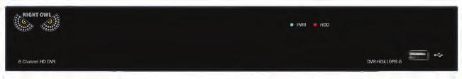
12 Chapter 3: Specifications 3.1 System Requirements Please be sure that your PC/MAC complies with the following specifications PC Operating System: Windows 7, Windows 8/8.1, and Windows 10 PC Browser: IE 8 and above, Edge, Google Chrome and Firefox MAC Operating System: MAC OS X 10.7 and above MAC Browser: Safari 7.1 and above Please be sure that your mobile device complies with the following specifications: Android : 4.0 and above ios : 7.1 and above 3.2 Package Contents 1 x HDA DVR Indoor/Outdoor Cameras* Bundles of Camera Cable* Mounting Hardware and Screws* HDMI Cable 1 x RJ-45 Cable (Ethernet) 1 x USB Mouse 1 x Remote Control (Includes Batteries) 1 x Software CD 1 x Support Material Packet 1 x Camera Power Adapter* 1 x DC 12V DVR Power Adapter Camera Power Splitters* 3 x Night Owl Security Stickers * Cameras, additional cables, power adapters, mounting hardware and splitters only included in certain security kits. Check the product packaging for detailed kit contents DVR Diagram QR Code Once you have downloaded Night Owl HD and connected your DVR to your router, you can network your DVR by scanning the QR code which is located on the top of the DVR. FRONT VIEW Model # 12 HDA Series Users Manual
13 REAR VIEW Images used are for reference only. Your product may vary slightly. An 8 channel model is displayed above. 1. Video Inputs video inputs allow for the connection of BNC cameras. 2. Audio Output audio output allows for the connection of an amplified speaker. 3. Audio Inputs audio inputs allow for the connection of audio-enabled cameras by connecting the white RCA plug to one of the audio inputs. After making the audio input connection, be sure to enable the audio function in the DVR s menu. Please ensure the audio input port number directly corresponds to the channel port number. For example, audio input port 1 provides audio to channel port HDMI Output HDMI output allows for the video connection. If the TV / Monitor has an HDMI input, connect the HDMI cable from the HDMI output port on the DVR to the HDMI input port on your TV / Monitor. 5. VGA Output VGA output also allows for video connection. While HDMI provides a higher quality video, you may connect a VGA cable from the VGA output port on the DVR to the VGA input port on your TV / Monitor if your TV / Monitor does not have an HDMI port. 6. RJ-45 (Ethernet) Port RJ-45 port will be used to connect the DVR to your router/ modem via the included Ethernet cable. Keep in mind, you can quickly network your DVR to begin viewing your cameras remotely right from your mobile device by completing the DVR s Startup Wizard once you have connected the DVR to your router and powered on the DVR. 7. USB Ports USB ports allow for the connections of a USB mouse and / or a USB flash drive. You will connect the included USB mouse to assist you in navigating the DVRs menu interface. You will connect a USB flash drive to download video files from the DVR and save them to your USB flash drive. 8. RS-485 (PTZ) Port RS-485 port allows for the connection of a Pan-Tilt-Zoom camera. 9. Power Input power input to connect the included 12V DC power supply. Chapter 3: Specification 13
14 3.2.2 Camera Diagram HD Resolution CAMERA NOTE: To ensure all the cameras are functioning properly, please test each one before installing them. To test: attach the camera side of a BNC cable to each camera while the DVR side is connected to the DVR and camera power adapter. 14 HDA Series Users Manual
15 3.2.3 Mouse and Remote Diagram MOUSE Live Viewing: Double-click the left button on any camera view in split-screen mode to bring it to full screen display. Double-click again to return to split-screen mode. Right-click to show the control bar at the bottom of the screen. Right-clicking again will hide the control bar. In Setup: Left-click to make a selection. Right-click to cancel setup or return to previous screen. To Enter Values: Move the cursor to a blank field and click the mouse. A virtual keyboard will appear which supports numbers, letters and symbols. The Shift function will access symbols in addition to upper case letters. Chapter 3: Specification 15
16 REMOTE 16 HDA Series Users Manual
17 CHAPTER 4 CAMERA INSTALLATION Chapter 4: Camera Installation SUPPORT VIDEOS 17
18 Chapter 4: Camera Installation 4.1 Video/Audio * NOTE: Connect all cameras locally before final placement to ensure that all components function properly. 1. Locate an included 60 foot camera cable. 2. Connect a camera to one end of the cable by matching the BNC connectors (yellow) and DC power connectors (red). 3. Audio enabled cameras will have an additional (white) RCA connection which will transmit the audio signal and will connect to the audio in port on the back of your DVR. 4. Plug BNC connectors on the other end of the cable into a Video Input port on the back panel of the DVR. 5. Repeat for each camera, noting the channel number each camera is plugged into. 4.2 Power Standard Camera Power 1. Locate an included power splitter. 2. Connect the power splitter to the remaining DC power connectors (red) of the cables. 3. Plug the power splitter into the labeled camera power supply, then plug the camera power supply into an available wall outlet or UPS. Keep in mind, Night Owl always recommends utilizing a surge protector to minimize the risk of damage caused to your DVR in the event of a power surge. 18 HDA Series Users Manual
19 * Cameras, additional cables, power adapters and splitters only included in certain security kits. Check the product packaging for detailed kit contents. Make sure all cameras are working prior to mounting by connecting them as described in the section above. Once all cameras are confirmed to be fully operational, you can run the cables and mount the cameras at their final locations Integrated Battery Backup Camera Power* 1. Locate all included power splitters. 2. Connect the power splitters to the remaining DC power connectors (red) of the cables. 3. Plug the power splitters into the labeled Camera Power Output ports. *YOU MUST PLUG IN BOTH POWER SPLITTERS, REGARDLESS OF THE NUMBER OF CAMERAS YOU ARE CONNECTING Chapter 4: Camera Installation 19

20 Integrated Battery Backup units have a unique camera power splitter identified by the large splicer in the middle (circled in red) and the male connectors on all leads. 4.3 Mounting the Cameras Camera distance from DVR. The further the camera is from the DVR or monitor, the higher the chances of signal degradation. The camera s power supply should be located as near to the camera as possible Connect all cameras locally before final placement to when the distance exceeds 200 ft. ensure that all components function properly. as the power level will drop over extended distances resulting in video degradation. Do not place near high voltage wires or other sources of electrical interference. Electrical interference will degrade the quality of the signal. Place camera out of reach to avoid vandalism. Avoid direct exposure to weather. Do not place the camera where rain or snow will hit the lens directly nor should the camera be placed so that the sun or bright light shines directly into the lens. Your camera is weatherproof, but it will not work when submerged in water. Ensure that all power and video connections are not directly exposed to water and are protected from the elements. Mounting surface. The mounting surface must hold at least four times the camera s total weight. 20 HDA Series Users Manual
21 1. Locate a camera and choose a location where you would like to mount the camera. 2. Indicate screw positions by marking three holes on the surface where you plan to mount the camera, using the holes in the camera base as a guide. 3. Using a drill bit slightly smaller than the included screw anchors, drill into the mounting surface using the guide marks you placed in the previous step. 4. Insert the screw anchors. 5. Line up the camera base holes with the screw anchors. Holding the base in place, insert screws and tighten until secure. 6. Once the base is screwed in place, make sure that the camera is securely mounted by placing gentle pressure on the mount. 7. Adjust the camera housing to point in the direction of the area you would like to monitor. Don t feel like installing the system yourself? Let InstallerNet do the work for you! Contact us at or visit us at Chapter 4: Camera Installation 21
22 CHAPTER 5 DVR INSTALLATION Chapter 5: DVR Installation SUPPORT VIDEOS 23
23 Chapter 5: DVR Installation 5.1 Connecting to a TV (via HDMI) 1. Locate the included HDMI cable. 2. Plug one end of the cable into the HDMI port on the back of the DVR. 3. Connect the other end of the cable to an available HDMI input on your TV or monitor. 4. Select the appropriate video input channel on your TV or monitor to view the DVR. 23 HDA Series Users Manual
24 If your TV does not have an HDMI port, you will need to purchase a VGA cable. For a VGA connection, attach one end of the VGA cable to the DVR VGA port and the other end to your TV VGA port. 5.2 Power 1. Locate the labeled DVR power adapter; the camera power adapter and DVR power adapter should never be interchanged. DVR power adapter may vary slightly. Chapter 5: DVR Installation 24
, plug the adapter cable into one of its output sockets.")
25 2. Plug the DVR power adapter into the power input on the rear of the DVR. 3. Plug the other end of the DVR power adapter cable into an available wall outlet. If you are using an uninterruptable power supply (UPS), plug the adapter cable into one of its output sockets. Keep in mind, Night Owl always recommends utilizing a surge protector to minimize the risk of damage caused to your DVR in the event of a power surge. Pictured above: Night Owl s revolutionary battery backup designed for security DVR s. We recommend all customers utilize the battery backup with your DVR. nightowlsp.com/products/cables-accessories/accessories/bb-86ah.html 25 HDA Series Users Manual
26 *If your DVR has an integrated battery backup, please be sure to flip the power switch to the ON position! Chapter 5: DVR Installation 26
27 CHAPTER 6 GETTING STARTED Chapter 6: Getting Started SUPPORT VIDEOS 27


28 Chapter 6: Getting Started 6.1 Startup Wizard When your DVR is powered on it will display the Night Owl logo while initializing. Scan or click the QR code to view our Startup Wizard video which shows the quick and easy steps in detail. After initialization, you will be prompted to use the Startup Wizard. Follow the on-screen instructions to: Create a system user name and password. Connect your DVR to a router that is hard wired. The DVR cannot connect wirelessly to a router. Follow the Startup Wizard instructions to add your DVR to your mobile device. You can prevent the Startup Wizard from appearing each time the unit is rebooted by checking Don t display this wizard again. 28 HDA Series Users Manual

29 6.2 Night Owl HD Mobile App The Night Owl HD Mobile App allows you to access your DVR remotely on an Apple or Android smart device. You can easily configure motion activated push notifications to alert you whe one of your cameras detects motion. Additionally, you can live view your cameras from within the app. Once you have downloaded Night Owl HD and connected your DVR to your router, you can network your DVR by scanning the QR code which is located on the top of the DVR. 6.3 Displays and Icons The following sections will describe the 3 main screens you will access for login, playback, recording, and configuration Login Screen Any time you want to configure or adjust your system settings you will be required to log in by entering your user name and password. It s important you save your login info or you won t be able to access your DVR. Be sure to store your user name and password in a safe location. You will need this information to access the main menu. Chapter 6: Getting Started 29

30 Device ID: the value in the field should match the value in the parentheses on the right. These numbers verify which device you are currently viewing. User: enter the User name you created in the Startup Wizard or User Menu. Password: enter the Password you created in the Startup Wizard or User Menu. If the password is incorrect you will be prompted to try again. Keep in mind the password is case sensitive and must be 8 characters long Live View (All Channels) Live View is the default screen you will see when viewing all channels on your DVR. Right-click anywhere on-screen to bring up the icon menu to change viewing options or access the main menu. Rearrange the channel order by left clicking and dragging individual channels to other locations in the on-screen layout. 1 2 R Date and Time: current date and time of the system. 2. Channel Name and Number: channel name and number. 3. Menu: access the main menu to configure or adjust settings Be sure to store your user name and password in a safe location. You will need this information to access the main menu. 4. Lock Screen: manually locks or unlocks screen. Once the screen is locked, you will need to enter your user name and password to gain access. 5. Quad View: 4 channel viewing layout Channel View: 9 channel viewing layout. 30 HDA Series Users Manual
31 7. Recording: indicates when a camera is currently recording. 8. Multi-view: various layout options for viewing multiple channels at once. 9. Auto Sequence: start/stop the slideshow sequence of each channel. 10. Volume: mute or adjust the system volume. 11. PTZ: open up the Pan, Tilt, Zoom (PTZ) menu. This function will only work when a PTZ camera is connected to your DVR. 12. Cruise: starts /stops the cruise function of your PTZ camera. 13. Picture-in-Picture 1: view channel 1 with an inset window showing another channel. 14. Playback: access the recording/playback menu and functions Live View (Single Channel) When in Live View, select a single channel to bring up additional controls and playback options. By double-clicking on the channel you can also view that channel in full screen mode Manual SnapShot: click to snapshot a single still image. 2. Manual Record: click to begin recording the selected channel. 3. Instant Playback: replay video footage stored on the HDD. 4. Zoom: click and drag an area to zoom in and enhance. Right-click to return to the normal view. 5. Color Setting: adjust the channel hue, contrast, brightness, and saturation. Chapter 6: Getting Started 31
32 6.3.4 Menu Screen Access the main menu by right-clicking anywhere while in Live View and then selecting the menu icon. From within the main menu you will be able to access settings and parameters for all aspects of your DVR system General Menu: configure display, network, and alarm settings. 2. Cameras Menu: access channel display and color settings. 3. Record Menu: setup or modify general recording, triggered events, and recording settings. 4. Device Menu: monitor available HDD space and access PTZ settings. 5. System Menu: access general settings such as timestamp displays, user access, system info, and access logs. 6. Advanced Menu: view and change maintenance settings, upgrades, and HDD alerts. 32 HDA Series Users Manual
33 CHAPTER 7 MENUS AND SETTINGS SUPPORT VIDEOS 33
, then select the channel you would like to copy the information to from the second dropdown box (To).")
34 Chapter 7: Menus and Settings Some menu screens will allow you to copy similar settings to multiple channels. Choose the channel you would like to copy information from in the first dropdown box (Copy), then select the channel you would like to copy the information to from the second dropdown box (To). Click Copy when the proper channels have been chosen. Be sure to Save all changes you make in the menus. If you do not save the changes, they will not be applied. You can also select the Default button on any page to restore default settings for those parameters. 34 HDA Series Users Manual

35 7.1 General Menu The general menu will allow you to access display, network, and alarm settings for your DVR system Display a. Output: adjust the display resolution on your TV or monitor. Video Output: defaulted to LIVE-OUT. Sequence View: set the channel order when viewing in sequential mode. Sequence Time: adjust the duration each channel is displayed during a sequential view. You can select between 1 and 300 seconds per channel. To begin the auto sequence feature, click on the Auto Sequence icon which is located on the quick access bar. VGA/HDMI Resolution: optimize the display resolution to best fit your TV/monito. By default, the optimal resolution option will be selected automatically by the DVR. Transparency: modify the menu transparency when displayed on screen. Support Overscan: select this option if using a TV or monitor that overscans (crops) the camera footage Chapter 7: Menus and Settings 35


36 b. Privacy Zone: create or modify up to 4 privacy zones per channel. These zones will not be visible to the cameras in Live View or during any recording. Channel: choose which channel to apply a privacy zone to. Privacy Zone: Enable or Disable privacy zones on the selected channel. Area Setup: select the number of masks you would like to create or modify. Mask Area: a single Live View of the selected channel will be displayed with the number of Areas selected in the previous line. Select, drag, and resize each area by left clicking the mouse to mask areas on camera that you do not want visible while recording or monitoring. Once the area(s) are selected, right-click to return to the menu. 36 HDA Series Users Manual


37 7.1.2 SnapShot a. SnapShot: turn channel SnapShot capabilities on or off. Channel: Select channel to edit. Auto SnapShot: Enable/disable snapshot feature on selected channel. Stream Mode: Select mode of streaming: Mainstream = native resolution and frame rate; Substream = optimal resolution and frame rate equal to bandwidth available Normal Interval: Time in between snapshots in seconds for normal recording. Alarm (Motion) Interval: Time in between captures in seconds for motion recording. Manual SnapShot: Enable/disable ability to snapshot a still image manually. b. SnapShot Schedule: set parameters for snapshot situations. For example, from this menu you can configure your camera on channel one to snapshot from 1pm-9pm (Scheduled) and the remaining cameras to begin capturing only when motion is detected (Motion). Chapter 7: Menus and Settings 37

38 7.1.3 Network a. Main: find network values and optimize connectivity based o your Internet connection. In most cases the values should populate automatically once your DVR is connected to the Internet. The values in this section should only be adjusted if you are an advanced user and have extensive experience in device networking. PPPOE: for broadband dial-up network users only. You will need to contact your ISP to retrieve the User Name and Password needed to complete this type of connection. DHCP: the most common network connection type. These values will be gathered automatically from your ISP when connected. Static: modify these values if you are using a static IP address. Information can be obtained from your router and ISP. Media Port: allows access to your DVR from a mobile device. The default value of 9000 should generally be used for most cases. Web Port: allows access to your DVR with your computer through your LAN or the Internet. In most cases the default value of 2049 or 2051 will provide the most optimal connectivity. IP Address: network address of the connected DVR. Subnet Mask: the range of IP addresses that can be found in the network. This should always be set to the default address Gateway: the connection between two networks. This should always be the IP address of the connected router. DNS1: primary Domain Name System server address. DNS2: secondary Domain Name System server address. UPNP: Enable or Disable Universal Plug and Play abilities depending on your network device capabilities. 38 HDA Series Users Manual

39 b. Substream: configure or optimize the video quality of your Live View. Channel: select the channel to edit. Resolution: choose your desired resolution for the selected channel. FPS: increase or decrease the frames per second of the streaming video depending on your connection speed. A higher FPS will result in more data transfer but smoother video. A lower FPS will eliminate most lag but at the expense of video quality. Bitrate (Control/Mode): adjust the amount of data transferred while streaming. The default settings are sufficient for most networks. Audio: click the tick box to record sound if your camera is audio enabled. Not all cameras are audio enabled; audio enabled cameras will have a white RCA connector to transmit the audio signal. c. Enable or Disable alerts based on your alarm settings. SSL: Enable or Disable to send encrypted alerts. SMTP Port: the access point for your determined by your service provider. SMTP Server: this is the mail server address of your provider. This information is determined by your provider. Sender: the address that will send alerts. Chapter 7: Menus and Settings 39


40 Sender: the address that will send alerts. Sender Password: the password for the address provided in Sender. Receiver: the address that will receive the alerts. Interval: set the duration between sending s for multiple alerts. d. Schedule: choose when alert s can be sent. Select Motion or Exception above the calendar and click the corresponding green or red boxes; you can highlight multiple boxes by left clicking and dragging. Highlighted boxes represent days and times in which s will be sent. Motion refers to alerts sent when cameras are triggered by motion and Exception refers to events such as video loss or memory conflicts e. DDNS: Enable or Disable DDNS service to view your DVR from a computer. Server: set to the NIGHTOWL server when using the Night Owl free domain name server. Domain: set to the domain name you created when registering your DDNS. User: the UserID created during the DDNS registration process. Password: the password created during the DDNS registration process. 40 HDA Series Users Manual

41 7.1.4 Alarm a. Motion: configure the motion alarm settings for your DVR system Channel: select the channel to configure motion alarm settings. Motion: enable motion alarms. Buzzer: enable audible alarm. Sensitivity: adjust the level of motion detection. A lower setting will require more movement in the camera range to begin recording. Motion Area: clicking Setup will allow you to configure areas which will and will not detect motion. Red boxes denote areas that will detect motion and uncolored boxes show areas that will not. When finished, right click to go back to menu. Post Recording: set the amount of time to record after the motion is detected. You can select between 30 and 300 seconds. Show Message: check the tick box to enable the display of a red M on-screen while in Live View mode. M means motion is occuring. Send check the tick box to send an alert when motion is detected. See section for setup and configuration. Full Screen: when this tick box is checked, the selected channel will go to full screen when motion is detected. Push: selecting this tick box will enable push notifications to your mobile device when motion is detected in the selected channel. The default setting is on. Record Channel: this option gives you the ability to start recording on the channels you select/highlight as soon as motion has been detected on the Channel selected above within the Channel field Chapter 7: Menus and Settings 41

42 b. Setting Detection Area When it comes to protecting your loved ones, why not go with the best? Night Owl s Smart Detection Security System uses both motion sensors and infrared sensors to ensure the number of false alerts produced are minimal. Current motion detection technology allows your system to begin recording when a pixel change is detected by your unit. With the incorporation of infrared sensors, now your system must detect both a pixel change and a change in heat in order for your system to record when set to motion. Night Owl utilizes high tech UTC cabling which sends a signal from the camera to the DVR. If configured, the DVR will then send a push notification out to your Smart Device which will contain an embedded video clip of the object triggering the motion and infrared sensors. In order to set the PIR Detection Area for your PIR camera, first log in to your DVR s Main Menu then navigateto General > Alarm. Choose the channel you want to configure from the drop down menu labeled Channel and then click the Setup button. You will be directed to the detection area screen. By default, all squares should be red, indicating the entire field of view is set to detect heat change. If there is an area within the camera s field of view that you do not want detection to be active, follow the steps below: 1. Click on a square in one corner of the area you don t want to be detected 2. Click and drag the mouse over the area you want to block 3. Release the mouse and verify you have selected your desired area 4. Right click the mouse and select Save 42 HDA Series Users Manual

43 7.2 Cameras Menu Adjust or modify individual camera settings connected to your DVR Settings Channel: select the channel you want to configure a camera for. Channel Name: create a name for the selected channel; this name will be displayed on-screen during Live View and playback. Show Name: display the channel's name on screen. Record Time: Enable or Disable the recording time display on-screen during playback mode. Position: change the position of Channel Name while viewing in Live View. Color: click Setup to access a sub-menu to adjust the colors of the selected channel. In this sub-menu you can adjust the Hue, Brightness, Contrast, and Saturation of the image. Covert: Enable or Disable the display of this channel. Enabling the Covert mode will not affect the channel s recording functions, it will only block the channel while viewing in live view mode. Show Time: Enable or Disable the on-screen time stamp during live view mode. Chapter 7: Menus and Settings 43


44 7.3 Record Menu From this menu you can enable recording, set video settings, and adjust streaming options General (Playback) Search and playback all recorded video from this menu. Choose your desired date and times from the options below, then click Play to view recorded video. Right-click to exit back to the menu screen. Channel: select the channel you would like to playback footage from. Type: search All, Normal or Motion video to playback. Playback Channel: choose the desired channel to view footage from. Start Time: set the initial time parameter for your video search. End Time: set the end time parameter for your video search Calendar: indicate the date to playback video. 2. Channel Selection: choose the channels to display on-screen. 3. Full Screen: hides the Calendar and Channel Selection panels. 4. Rewind: rewinds the recorded video HDA Series Users Manual

45 5. Slow Forward: forwards the video at a slower speed. 6. Play: plays video starting at the indicator on the timeline. 7. Pause: pause the recorded video. 8. Stop: stop the recorded video. 9. Fast Forward: fast forward frame-by-frame of the recorded event. 10. Zoom: click the icon and select the area on-screen to zoom in. 11. Clip/Save: click once to set the start point of the video you would like to save. Press the icon again to select the end point of the video you would like to save then choose whether you would like to save as an H.264 or AVI format. 12. Volume Scale: adjust the volume of the video in the selected channel(s). 13. Start Time: indicates the beginning of the timeline on the selected Calendar date. 14. End Time: indicates the end of the timeline. 15. Timeline Length (24h, 2h, 1h, 30m): select the duration of the on-screen display of the timeline. 16. Exit: double right click the mouse or click on the X to exit the playback screen Events and Pictures Search for video from triggered events and quickly backup the video files for future reference. You can select either All, Normal, Motion, or Manual. Date: select the date to search for event. Time: choose a start and end time that the event happened. Channel: pick the channel(s) with the desired event. Type: select from All, Normal, or Motion event. (Picture menu also has a Manual option) Quick Backup: check the boxes to the left of the found videos clip(s) and click this button to save that file to a USB Flash Drive. ou can also Playback by right clicking on the icon located in the playback section. Search: once the parameters are set, click this button to retrieve manual event from the specified time period. You can choose to save your video as an AVI, MP4, or H.264 format. Chapter 7: Menus and Settings 45


46 7.3.3 Settings (Recordings) View or modify general recording settings for your DVR system. a. Basic: turn channel recording capabilities on or off. Channel: select the channel you would like to configure. Record: Enable or Disable recording capabilities for this channel. Pre-Record: Enable or Disable pre-recording for this channel. Pre-recording is the amount of video captured prior to an alarm being triggered. Stream Mode: select either Mainstream (high resolution) or Substream (low resolution). NOTE: By default, the DVR is configured to begin recording when motion is detected. b. Record Schedule: set parameters for recording situations. For example, from this menu you can configure your camera on channel one to record from 1pm-9pm (Scheduled) and the remaining cameras to begin recording only when motion is detected (Motion). 46 HDA Series Users Manual
47 Channel: select the channel to configure the recording schedule Normal Record: select this option to set the schedule for continuous recording. Once selected, highlight the boxes corresponding to the day and times that the channel should be recording. Click and drag to highlight multiple boxes green. Motion Record: select this option to set the schedule for motion-activated recording. Once selected, highlight the boxes corresponding to the day and times that the DVR should record when motion is detected. By default, motion recording is always on. c. Mainstream: configure or adjust the video settings to best optimize your connection Channel: select channel to edit Resolution: choose between 960H (960 x 480), 720p (1280 x 720) or 1080p (1920 x 1080) resolutions based on your TV or monitor capabilities. FPS: increase or decrease the frames per second of the streaming video depending on your connection speed. Higher FPS equals better video quality. If experiencing lag or stutter, lower the FPS. Bitrate Control: select CBR (constant bit rate, or a fixed encoding speed) or VB (variable bit rate, or an average encoding speed); if using VBR, you must select the desired quality of video. Bitrate Mode: select Predefined to auto-select bitrate or User-Defined to set bitrate manually. Bitrate: adjust the amount of data transferred while streaming. The default setting is sufficient for most networks Audio: click the box to record sound if your camera is audio enabled. Audio enabled cameras are only included in certain kit models. Chapter 7: Menus and Settings 47


48 7.4 Device Menu HDD Check available memory on your DVR HDD and set recording parameters to optimize storage. Select: if multiple drives are installed, choose the HDD you would like to customize. Overwrite: by default, the Auto setting will overwrite the earliest footage once the HDD is full. Choose one of the other options to overwrite footage at the end of the desired time duration, starting with the earliest data. Off will record until the HDD has reached capacity. Format HDD: click this button to format the selected drive. Keep in mind, formatting the HDD will erase all video files from the HDD PTZ Configure settings on your DVR to control a PTZ-enabled camera Channel: choose the channel with a PTZ-enabled camera. Not all cameras are PTZ enabled. 48 HDA Series Users Manual

49 Protocol: select Pelco-D or Pelco-P depending on the camera protocol. Both the DVR and camera should be set to the same setting. Baudrate: indicates the frequency of communication to the PTZ camera. We recommend leaving the default setting which is DataBit: select the amount of data to send during each transmission. 8 bits is standard for all modern data transmissions. StopBit: select the amount of extra data to send each time a direction is sent to the camera. The stopbit serves as a buffer between commands and should be 1 (by default) when utilizing Night Owl s AHD PTZ camera. Parity: detects corrupt commands sent to and from the PTZ camera. This should generally be left Disabled. Cruise: Enable or Disable the PTZ cruise function, which allows the camera to automatically scan the area periodically with no manual input. Address: enter an ID number for the PTZ camera, greater than 0. If using multiple PTZ cameras, ID numbers cannot be the same. 7.5 System Menu General Set or adjust basic DVR settings such as the time, date, and language. a. Settings: basic system configuration Date: manually set the date by left clicking on the calendar icon Time: manually set the time by left clicking inside the time field Date Format: choose the display format for the date. You can select Month/Day/ Year, Year/Month/Day or Day/Month/Year. Time Format: select between a 12Hour or 24Hour display. Chapter 7: Menus and Settings 49
50 Language: pick between ENGLISH, SPANISH or FRENCH language preferences. Video Format: NTSC or PAL formats are available to choose from. NTSC is the standard for video in North America. Menu Timeouts: select the duration of time for an inactive menu to be displayed on-screen. Show Wizard: check the tick box to display the Startup Wizard each time the DVR is powered on. Mobile Wizard: click the mobile icon to launch mobile application setup portion of the Startup Wizard. b. DST: configure Daylight Savings Time settings. DST: Enable or Disable the Daylight Savings Time feature. Time Offset: choose the amount of time (1Hour or 2Hours) to offset if DST is enabled. Daylight Saving Time: indicate whether you would like this feature to be applied the week of or an exact date. Start Time: select the date and time to apply the DST offset. End Time: select the date and time to remove the DST offset. c. NTP: sync your DVR to the Network Time Protocol standard time and date. NTP: Enable or Disable the NTP sync feature. Server Address: choose the NTP server in which to sync the date and time with. Time Zone: indicate your current or desired time zone. Update Now: after selecting the above options, click this button to apply the settings. 50 HDA Series Users Manual


51 7.5.2 Users Create and modify user s permissions. Edit: select an existing user from the list to change the User Name, Enable or Disable password access, or create a new Password. Permission: select a user profile (e.g. user1) and press the Permission button to select which menus, settings, and playback/recording functions are available to that specific user and on which channels. All will give that user basic admin settings. Chapter 7: Menus and Settings 51


52 7.5.3 Info a. Info: View your DVR system s information and specifications at a glance This menu will provide crucial device and network information to allow manual reconfiguration of your mobile application if needed. Keep in mind you can als scan the QR code on this screen using your Night Owl HD mobile application to quickly reconfigure your mobile device via our Owl Scan feature Device ID: create a unique device ID number if you are using multiple DVRs. Device Name: create a unique device name for easy reference. Device Type: product model number. Hardware Version: the current hardware version. Software Version: your current software version. IE Client Version: the current IE client version. IP Address: the current DVR network address. MAC Address: the DVR media access control address on the network. HDD Capacity: the max capacity of installed hard drives. Video Format: the current video recording format. Media Port: by default should be left at Web Port: by default should be left at 2049 or P2P: the ID of your Peer to Peer (P2P) connection. b. Channel Info: Displays an overview of the current video settings for all channels. View alias, state, mainstream/substream playback information, mobile support, motion detection, and privacy zone information. The settings on this page cannot be edited. 52 HDA Series Users Manual


53 c. Record Info: Displays an overview of the current record settings for each available channel. View record state, stream type, frames per second (FPS), bitrate, and resolution information. The settings on the page cannot be edited Log Search for logs of all events and notifications on the DVR to playback or backup file Start Date: choose the initial date of your log search period. End Date: choose the end date of your log search period. Start Time: choose the initial time of your log search period. End Time: choose the end time of your log search period. Log Type: select the type of event log that you would like to Search for. Each choice corresponds to an action or event that was triggered and noted within the system. For example, System logs are recorded when the DVR time is synced with NTP (if enabled) or if the system is turned on or off. Chapter 7: Menus and Settings 53
 you would like to save, and then select the drive to save to. 7.6 Advanced Menu Configure additional settings related to maintenance, hard drive space, and upgrades. 7.6.1 Maintain Adjust settings related to default user access and reboot schedules.")

54 Backup: in order to save a log, a USB flash drive must be inserted into one of the available USB ports on the back of the DVR. Select the log(s) you would like to save, and then select the drive to save to. 7.6 Advanced Menu Configure additional settings related to maintenance, hard drive space, and upgrades Maintain Adjust settings related to default user access and reboot schedules. Default User: select the default user account. Auto Reboot: Enable or Disable the automatic reboot feature. Reboot: set the frequency of reboots if this feature is enabled. Update: if any of the above settings were changed, click this button to save the new parameters. Load Default: revert back to the standard reboot schedule. Save Settings: save reboot settings to a USB flash drive Load Settings: load previously saved settings from a USB flash drive Shutdown: display the power menu (Shutdown, Reboot, Cancel). 54 HDA Series Users Manual
55 7.6.2 Events Configure notification settings for other triggered events not related to motio detection such as disk error, disk full or and/or video loss. Event Type: choose the type of event you would like to create a notification fo. Disk Full means you will receive a notification if the HDD is full. Disk Error refers to the status of the HDD and will notify you if it crashes or has become corrupt. Video Loss is the absence of video due to power loss. Enable: turn notifications on or off for the selected Event ype. Show Message: enable an icon to be displayed in Live View when the Event Type is triggered. Send send an notification when the Event ype is detected. Buzzer: turn an audible buzzer on for a duration of time to alert you when this Event Type happens. Choose OFF to disable this feature. You can select between 10 and 60 seconds. Chapter 7: Menus and Settings 55

56 7.6.3 Auto Upgrade Control settings for auto upgrades of the DVR software. Auto Upgrade: Enable or Disable the auto upgrade feature. Firmware updates will be detected automatically when this feature is enabled. The default selection for the auto upgrade feature is enable. Check For Updates: check this box to periodically search for updated software versions. Detect: click this button to check if you have the most current software version installed. Upgrade: if an upgrade is detected, click this button to download and install the new version. 56 HDA Series Users Manual
57 CHAPTER 8 REMOTE ACCESS 57 HDA Series SUPPORT Users Manual VIDEOS
58 Chapter 8: Remote Access This chapter will show you how to connect your DVR to the Internet. You will learn how to properly connect your DVR to you router/modem, complete DDNS registration, and setup port forwarding, Internet, and mobile configurations 8.1 System Requirements You will need to have the following in order to be able to successfully connect the DVR to the Internet. High-speed Internet connection Router or modem with two open Ethernet ports MAC (OS X 10.7 and above) or PC (Windows XP and above) with Safari, Internet Explorer (7 and above), Edge, Google Chrome, or Firefox installed 2x Ethernet cables (1x included with the system; see image below) 8.2 Setup Learn how to connect the DVR to your router/modem. Ethernet DVR Router (Not Included) NOTE: Do not connect the DVR to a wireless router. Chapter 8: Remote Access 58


59 8.3 Network Configuration Windows Operating Systems Make sure that the DVR is properly connected to the router/modem and that you have a computer that works with Windows and connected to the same router. Follow these steps to determine basic information about your network: 1. Press the Windows and R key at the same time on your computer s keyboard to bring up the Run window. Type cmd and press the Enter key. 2. In the command prompt window, type ipconfig and press Enter. Find the section named Ethernet adapter Ethernet or Wireless LAN adapter Wi-Fi and locate the IPv4 Address and write this address down e.g Change the last three digits of the address to 150 and write this address down as well e.g This will become the IP address of your DVR at a later time. 4. Find Default Gateway in the same section and write this number down as well e.g You will need to enter this in the DVR network settings. 59 HDA Series Users Manual
60 For the following steps, use the information that you just wrote down. To access the network settings on your DVR, go to the General Menu, then to Network > Main and choose the Static option. 1. Manually enter the IP address into the IP Address field; this is the numbe that ends with 150. You may have to add placeholder zeros for any sections that do not contain three digits e.g Confirm that the Subnet Mask is set to Enter the Default Gateway number from the prior section into the Gateway field. Again you will need to add placeholder zeros in any sections that do no contain three digits e.g Chapter 8: Remote Access 60
61 4. DNS1 and DNS2 fields are auto-populated in most cases, if they are not the need to be set as follows: DNS1: [Gateway] DNS2: Click the Save button to apply all changes. 6. Reboot or power cycle the DVR. NOTE: Write these addresses down in the User Information section at the end of the manual for future reference Mac Operating Systems Make sure that the DVR is properly connected to the router/modem. Follow these steps to determine basic information about your network: 1. Click the Apple logo in the top left of your screen, select System Preferences, then select Network. 2. Choose Ethernet and select the Advanced button in the lower right corner. 3. Select the TCP/IP tab at the top to display your computer s network information. 4. Write down the IPv4 address. 5. Change the last three digits of the address to 150 and write this address down as well e.g This will become the IP address of your DVR at a later time. 6. Make note of the IP address listed for Default Gateway. You will need to enter this into the DVR network settings. 61 HDA Series Users Manual
62 For the following steps, use the information that you just wrote down. To access the network settings on your DVR, go to the General Menu, then to Network > Main and choose the Static option. 1. Manually enter the IP address into the IP Address field; this is the numbe that ends with 150. You may have to add placeholder zeros for any sections that do not contain three digits e.g Confirm that the Subnet Mask is set to Enter the Default Gateway number from the prior section into the Gateway field. Again you will need to add placeholder zeros in any sections that do no contain three digits e.g Chapter 8: Remote Access 62
63 4. DNS1 and DNS2 fields are auto-populated in most cases, if they are not the need to be set as follows: DNS1: [Gateway] DNS2: Click the Save button to apply all changes. 6. Reboot or power cycle the DVR. NOTE: Write these addresses down in the User Information section at the end of the manual for future reference Port Configuration After you have configured the network settings, you will need to forward the necessary ports to be able to view the DVR over the Internet. Refer to your router s documentation to see how port forwarding works for your device. This process may be referred to as Port Forwarding, Port Mapping, or Virtual Server. Below are some general considerations to keep in mind to make sure that the appropriate ports are forwarded: 1. Go to Your public IP address will appear at the top of the page; write this number down. 2. Open a browser window and type in your IP address in the URL bar. 3. Log in to your router using your user name and password. If you do not know your router s user name and password you will need to contact your ISP or the router manual/support documentation to retrieve that information. 63 HDA Series Users Manual
64 4. Once logged in to your router, go to the settings related to port forwarding. 5. You will need to enter a new port forwarding entry for each port that your DVR uses: Media Port (9000), Web Port (2049 or 2051). Repeat the steps below for each entry. 6. When entering the port numbers and IP address into your router s port forwarding section, you will need to remove any leading zeros e.g , , etc. 7. Additionally most router menus will ask you to enter the following information in order to forward a port; the language and naming on your particular router may be different than below but the same principles will apply: Application Name: create a unique name for your DVR system. Public Port: select the port to forward: Media Port (9000), Web Port (2049 or 2051), or Server Port (2050). Private Port: set to the same number you entered for the Public Port. Port Type/Protocol: if your router has an option for both, use TCP and UDP. If your router allows either TCP or UDP port types, use TCP. Host IP Address: set to your DVR IP address ending in 150 that you wrote down earlier. Once you have forwarded the necessary ports on your router, you should check to make sure they have been correctly forwarded. 1. Go to 2. Type in port 9000 and select the Check button to see if the port is open or closed. 3. Type in port 2049 or 2051 and select the Check button to see if the port is open or closed. 4. All ports should be open. If any ports test as closed, that port is not forwarded correctly. NOTE: Write your external address in the User Information section at the end of the manual. Chapter 8: Remote Access 64


65 8.3.4 DDNS Registration This option allows you to set up a free website address that will point back to the DVR, regardless of whether or not the IP address changes. If you do not have a static IP address, you should use this option. Follow the steps below to register a free domain name/ddns. 1. Go to 2. Select the Registration button located at the top left corner of the page. 3. Complete the New User Registration form. Write down the UserID and Password information. 4. Create a domain name. If the domain name that you have chosen is available, you will see a window that tells you that your domain was successfully created. If the domain name is taken, try again until you find an available name NOTE: Write the registered domain name down in the User Information section at the end of the manual. 65 HDA Series Users Manual
NX-series User Manual
 NX-series User Manual http://www.iviewtech.com 1 CONTENT INDEX 1 NX-SERIES OVERVIEW... 4 1.1. NX-Series Features 4 1.2. NVR CONTROL PANEL 5 1.3. NVR BACK PANEL 5 2 GETTING STARTED... 8 3 LIVE VIEW... 10
QUICK START GUIDE. QT Analog HD Camera & DVR Bundle ENGLISH
 QUICK START GUIDE QT Analog HD Camera & DVR Bundle ENGLISH Table of Contents Welcome What s Included...3 Understanding your DVR...4 Get Connected Registration...5 Connect Your Cameras...5 Connect DVR to
QUICK START GUIDE. IP Camera & NVR Bundle ENGLISH
 QUICK START GUIDE IP Camera & NVR Bundle ENGLISH Table of Contents Welcome What s Included...3 Understanding Your NVR...4 Get Connected Registration...5 Connect Your Cameras...5 Connect Your NVR...6 Powering
EL-NVR. Quick Start Guide
 EL-NVR Quick Start Guide ABOUT THIS DOCUMENT This document includes instructions for basic operating the EL-NVR 5-Megapixel Series Network Video Recorder. ELECTROMAGNETIC COMPATIBILITY (EMC) This equipment
QUICK START GUIDE QT ANALOG HD CAMERA & DVR BUNDLE ENGLISH
 QUICK START GUIDE QT ANALOG HD CAMERA & DVR BUNDLE ENGLISH Table of Contents Welcome What s Included...3 Understanding your DVR...4 Get Connected Registration...5 Connect Your Cameras...5 Connect DVR to
Part 1 Basic Operation
 This product is a designed for video surveillance video encode and record, it include H.264 video Compression, large HDD storage, network, embedded Linux operate system and other advanced electronic technology,
1. Get support Attention Safety Caution Applications View Cameras on Screen (ex. HD TV or PC monitor) 3. Change Time Zone 5
 3. Change Time Zone 5") 1. Get support 1 2. Attention 1 3. Safety Caution 1 4. Applications 1 5. View Cameras on Screen (ex. HD TV or PC monitor) 3 Change Time Zone 5 6. Installation Guide for ONWOTE Cameras 6 7. View Cameras
1. Get support 1 2. Attention 1 3. Safety Caution 1 4. Applications 1 5. View Cameras on Screen (ex. HD TV or PC monitor) 3 Change Time Zone 5 6. Installation Guide for ONWOTE Cameras 6 7. View Cameras
Digital Video Recorder
 Digital Video Recorder Quick Operation Guide UD.6L0202B0067A02 Thank you for purchasing our product. If there is any question or request, please do not hesitate to contact dealer. This manual is applicable
IMPORTANT! This instruction guide explains how to install your CCTV system.
 IMPORTANT! This instruction guide explains how to install your CCTV system. Which accessories do you need before getting started? 1. Monitor or TV (recommended not less than 19" for clear viewing) 2. HDMI
Model#: IN-MDRI3MF. Hardware User Manual. 3MP Indoor Mini Dome with Basic WDR, Fixed lens. (PoE) Ver. 2013/02/04
 Ver. 2013/02/04") Model#: IN-MDRI3MF 3MP Indoor Mini Dome with Basic WDR, Fixed lens Hardware User Manual (PoE) Ver. 2013/02/04 Table of Contents 0. Precautions 3 1. Introduction 4 Package Contents... 4 Features and Benefits...
Model#: IN-MDRI3MF 3MP Indoor Mini Dome with Basic WDR, Fixed lens Hardware User Manual (PoE) Ver. 2013/02/04 Table of Contents 0. Precautions 3 1. Introduction 4 Package Contents... 4 Features and Benefits...
IMPORTANT! This instruction guides you how to install surveillance system.
 DIY Do-It-Yourself Quick Start Guide Network DVR with H.264 Compression IMPORTANT! This instruction guides you how to install surveillance system. What accessories you need before getting started 1.One
Wireless Cloud Camera TV-IP751WC (v1.0r)
") TRENDnet s, model, takes the work out of viewing video over the internet. Previously to view video remotely, users needed to perform many complicated and time consuming steps: such as signing up for a
TRENDnet s, model, takes the work out of viewing video over the internet. Previously to view video remotely, users needed to perform many complicated and time consuming steps: such as signing up for a
Model#: IN-DI2MIRF 2MP Indoor Dome with True Day/Night, IR, Basic WDR, Fixed lens
 Model#: IN-DI2MIRF 2MP Indoor Dome with True Day/Night, IR, Basic WDR, Fixed lens Hardware User Manual (PoE) Ver.2013/01/17 Table of Contents 0. Precautions 3 1. Introduction 4 Package Contents...4 Features
THD601DC Set-top box
 THD601DC Set-top box Contents 1. Safety... 1 2. Appearance... 2 3. Rear Panel Connection... 3 4. Remote... 4 5 First Time Set-Up... 7 6. Network Settings... 8 6.1 Available Networks and Checking Current
KODAK Video Monitor CFH-V10
 Quick Start Guide CAUTION RISK OF ELECTRIC SHOCK DO NOT OPEN CAUTION TO REDUCE THE RISK OF ELECTRIC SHOCK, DO NOT REMOVE COVER (OR BACK). NO USER SERVICEABLE PARTS INSIDE, REFER SERVICING TO QUALIFIED
SCode V3.5.1 (SP-601 and MP-6010) Digital Video Network Surveillance System
 Digital Video Network Surveillance System") V3.5.1 (SP-601 and MP-6010) Digital Video Network Surveillance System Core Technologies Image Compression MPEG4. It supports high compression rate with good image quality and reduces the requirement of
V3.5.1 (SP-601 and MP-6010) Digital Video Network Surveillance System Core Technologies Image Compression MPEG4. It supports high compression rate with good image quality and reduces the requirement of
SmartBox. User Manual. Turn your TV into a SmartTV! Plug n play. Wireless Dual Band
 SmartBox User Manual Turn your TV into a SmartTV! Wireless Dual Band Plug n play TV Remote Guide 5 4 1. ON / Stand by 2. Select package 1 6 2 3 7 3. 4. Favourite channels Electronic Program Guide (EPG
EVD-L04/100A1-960, EVD-L08/200A1-960 and. EVD-L16/400A1-960 DVRs. Quick Operation Guide
 EVD-L04/100A1-960, EVD-L08/200A1-960 and EVD-L16/400A1-960 DVRs Quick Operation Guide Thank you for purchasing our product. If there is any question or request, please do not hesitate to contact dealer.
DS-7200HVI/HFI-SH Series DVR Quick Operation Guide
 DS-7200HVI/HFI-SH Series DVR Quick Operation Guide UD.6L0202B0019A01 Thank you for purchasing our product. If there is any question or request, please do not hesitate to contact dealer. This manual is
SCode V3.5.1 (SP-501 and MP-9200) Digital Video Network Surveillance System
 Digital Video Network Surveillance System") V3.5.1 (SP-501 and MP-9200) Digital Video Network Surveillance System Core Technologies Image Compression MPEG4. It supports high compression rate with good image quality and reduces the requirement of
V3.5.1 (SP-501 and MP-9200) Digital Video Network Surveillance System Core Technologies Image Compression MPEG4. It supports high compression rate with good image quality and reduces the requirement of
CI-218 / CI-303 / CI430
 CI-218 / CI-303 / CI430 Network Camera User Manual English AREC Inc. All Rights Reserved 2017. l www.arec.com All information contained in this document is Proprietary Table of Contents 1. Overview 1.1
AHD. Quick Start Guide. DIY Do-It-Yourself. Network DVR with H.264 Compression
 AHD DIY Do-It-Yourself Quick Start Guide Network DVR with H.264 Compression A VIDEO DISPLAY Using a high quality monitor, connect it to DVR via VGA Cable or HDMI Cable. STEP 1 Turning on DVR STEP 2 Connect
DINOX&Digital&Video&Recorder&
 DINOX&Digital&Video&Recorder& & & & & & & & & & &&&Quick&Operation&Guide& UD.7L0X02B1228B01& Thank you for purchasing our product. If there is any question or request, please do not hesitate to contact
S-Series Server Setup Quiz
 1. In the System Setup window, System Information displays additional information such as: (a) IP Address (b) Modems (c) Sound Card (d) Video Channels and Audio Channels 2. You can change the Recording
Quick Operation Guide of LTN7700/7600 Series NVR
 Quick Operation Guide of LTN7700/7600 Series NVR UD.6L0202B0042A02 Thank you for purchasing our product. If there is any question or request, please do not hesitate to contact dealer. This manual is applicable
High Definition Home and Business Security Camera System QT IP HD
 High Definition Home and Business Security Camera System QT IP HD Table of Contents Getting Started Warranty 4 Understanding Your System What s Included 5 Understanding Your NVR: Front Panel 6 Understanding
EVD-L04/100A1-960 EVD-L08/200A1-960 EVD-L16/400A1-960
 EVD-L04/100A1-960 EVD-L08/200A1-960 EVD-L16/400A1-960 www.eurovideo-cctv.com Main Features Main stream supports encoding at up to WD1 resolution in real time and sub stream at CIF/QCIF resolution. Simultaneous
SwannSecure INSTRUCTION MANUAL
 SwannSecure EN INSTRUCTION MANUAL 1 Important Information FCC Verification This equipment has been tested and found to comply with the limits for Class B digital device, pursuant to part 15 of the FCC
DS-7200HFI-SL Series DVR. Technical Specification
 DS-7200HFI-SL Series DVR Technical Specification Notices The information in this documentation is subject to change without notice and does not represent any commitment on behalf of HIKVISION. HIKVISION
Content. General information. Main features. For your safety. Unpacking RCU. Front Panel. Real Panel. System wizard and activation.
 User manual This device complies with Part 15 of the FCC Rules. Operation is subject to the following two conditions: (1) this device may not cause harmful interference, and (2) this device must accept
HD TVI TURBO HD DVR Hikvision DS 7216HGHI SH/A (16ch, H.264, HDMI, VGA)
") HD TVI TURBO HD DVR Hikvision DS 7216HGHI SH/A (16ch, 1080p@12fps, H.264, HDMI, VGA) Code: M75216 Front view Rear view The included remote control http://www.dipolnet.com/document print M75216.htm 1/5
HD TVI TURBO HD DVR Hikvision DS 7216HGHI SH/A (16ch, 1080p@12fps, H.264, HDMI, VGA) Code: M75216 Front view Rear view The included remote control http://www.dipolnet.com/document print M75216.htm 1/5
GdVr 42/82 series security system. For more exciting new products please visit our website: australia:
 GdVr 42/82 series security system For more exciting new products please visit our website: australia: www.uniden.com.au OWNER S Manual important safeguards WarninG risk of electrical shock do not open
OPERATING INSTRUCTIONS TOM-0431IP
 OPERATING INSTRUCTIONS TOM-0431IP Table of Contents FCC Information -------------------------------------------------------------------- 2 Safety and Environmental Precautions ------------------------------------------------
4CH DVR, AS-DVR004A. AL - Aswar Trading Group Co., FEATURES. Pentplex ( Recording, Playback, Network simultaneously ) Up to 60fps Recording Speed
 Up to 60fps Recording Speed") 4CH DVR, AS-DVR004A FEATURES Pentplex ( Recording, Playback, Network simultaneously ) Up to 60fps Recording Speed USB flash disk backup Adjust Up/Down/Left/Right screen position Video Input signal: NTSC/PAL
4CH DVR, AS-DVR004A FEATURES Pentplex ( Recording, Playback, Network simultaneously ) Up to 60fps Recording Speed USB flash disk backup Adjust Up/Down/Left/Right screen position Video Input signal: NTSC/PAL
VNS2200 Amplifier & Controller Installation Guide
 VNS2200 Amplifier & Controller Installation Guide VNS2200 Amplifier & Controller Installation 1. Determine the installation location for the VNS2200 device. Consider the following when determining the
LOCAL MONITORING RECORDING HARDDISK MANAGEMENT ALARM & EXCEPTION BACKUP
 FEATURES User-friendly GUI for easy operation Up to 1024 768 resolution Simultaneous VGA and 4CIF/2CIF/CIF resolution Normal and event recording parameters configurable per individual camera Partial digital
D52. 3MP Indoor Dome with Fixed lens Hardware User s Manual. (PoE) Ver. 2012/12/12
 Ver. 2012/12/12") D52 3MP Indoor Dome with Fixed lens Hardware User s Manual (PoE) Ver. 2012/12/12 Table of Contents 0. Precautions 3 1. Introduction 4 Package Contents... 4 Features and Benefits... 5 Safety Instructions...
D52 3MP Indoor Dome with Fixed lens Hardware User s Manual (PoE) Ver. 2012/12/12 Table of Contents 0. Precautions 3 1. Introduction 4 Package Contents... 4 Features and Benefits... 5 Safety Instructions...
SwannSecure INSTRUCTION MANUAL
 SwannSecure EN INSTRUCTION MANUAL 1 Important Information FCC Verification This equipment has been tested and found to comply with the limits for Class B digital device, pursuant to part 15 of the FCC
GdVr 4t/8t series security system. For more exciting new products please visit our website: australia:
 GdVr 4t/8t series security system For more exciting new products please visit our website: australia: www.uniden.com.au OWNER S Manual important safeguards WarninG risk of electrical shock do not open
Owner s Manual & Safety Instructions
 Owner s Manual & Safety Instructions Save This Manual Keep this manual for the safety warnings and precautions, assembly, operating, inspection, maintenance and cleaning procedures. Write the product s
HD1080P 4 Camera CCTV System
 HD 1080P HD1080P 4 Camera CCTV System User Guide Version 1 Contents CHAPTER 1 FUNCTION DESCRIPTIONS AND FEATURES... 1 CHAPTER 2 CAMERA INSTALLATION... 2 2.1 BULLET CAMERA INSTALLATION... 2 2.1 DOME CAMERA
MAGICLiteSeries-16CH1080pDVRSystem-SupportsEX- SDI/HD-SDI/960H/Analog/IP
 MAGICLiteSeries-16CH1080pDVRSystem-SupportsEX- SDI/HD-SDI/960H/Analog/IP EX-SDI Magic Lite 1080p 16 CH MagicDVRdetectsAnalog/960H/EX-SDI/HD-SDIcamerasautomatically Records up to 4 IP cameras REAL-TIME
HD Digital MPEG2 Encoder / QAM Modulator
 HD Digital MPEG2 Encoder / QAM Modulator HDMI In QAM Out series Get Going Guide ZvPro 800 Series is a one or two-channel unencrypted HDMI-to-QAM MPEG 2 Encoder / QAM Modulator, all in a compact package
HD Digital MPEG2 Encoder / QAM Modulator Get Going Guide
 series HD Digital MPEG2 Encoder / QAM Modulator Get Going Guide HDb2640 HDb2620 HDb2540 HDb2520 The HDbridge 2000 Series is a combination HD MPEG 2 Encoder and frequency-agile QAM Modulator, all in a 1RU
Remote Control. degraded, causing unreliable operation. The recommended effective distance for remote operation is about 16 feet (5 meters).
.") Media Streaming Sound Bar RTS736W User Manual Remote Control using the remote control Point the remote control at the REMOTE SENSOR located on the unit (see Front Panel illustration for precise location).
Media Streaming Sound Bar RTS736W User Manual Remote Control using the remote control Point the remote control at the REMOTE SENSOR located on the unit (see Front Panel illustration for precise location).
MAGICUSeries-4CH1080pDVRSystem4Kouput- SupportsEX-SDI/HD-SDI/HD-TVI/A-HD/960H/Analog/ IP
 MAGICUSeries-4CH1080pDVRSystem4Kouput- SupportsEX-SDI/HD-SDI/HD-TVI/A-HD/960H/Analog/ IP Magic U 1080p 3MP 4 CH MagicUDVRdetectsAnalog/960H/HD-TVI/A-HD/EX-SDI/HD-SDIcameras automatically Records up to
16CH 1080p HD-SDI Security MAGIC Lite Series DVR System - Auto detects Analog/960H/HD-SDI
 HD-SDI Magic Lite 1080p 16 CH Magic DVR detects Analog / 960H / HD-SDI camera automatically. H.264 High Compression CODEC Programmable Spot Out iphone Android remote view App Available. Crystal clear 1080p
PLATINUM DIGITAL HD Professional HD Security System
 PLATINUM DIGITAL HD Professional HD Security System INSTRUCTION MANUAL 1 Important Information FCC Verification This equipment has been tested and found to comply with the limits for Class B digital device,
HD Digital Set-Top Box Quick Start Guide
 HD Digital Set-Top Box Quick Start Guide Eagle Communications HD Digital Set-Top Box Important Safety Instructions WARNING TO REDUCE THE RISK OF FIRE OR ELECTRIC SHOCK, DO NOT EXPOSE THIS PRODUCT TO RAIN
HD Digital MPEG2 Encoder / QAM Modulator
 HD Digital MPEG2 Encoder / QAM Modulator YPrPb VGA In QAM Out series Get Going Guide ZvPro 600 Series is a one or two-channel Component or VGA-to-QAM MPEG 2 Encoder/ Modulator, all in a compact package
8 CH MJPEG DVR USER MANUAL
 8 CH MJPEG DVR USER MANUAL Contents 1. SAFETY PRECAUTIONS... 3 2. FEATURES... 4 3. PACKING LIST... 5 4. NAME and FUNCTION of EACH PART... 6 4.1 FRONT PANEL BUTTONS and CONTROLS... 6 4.2 REAR PANEL BUTTONS
MAGICUSeries-32CHDVR4Koutput-SupportsEX-SDI/ HD-SDI/HD-TVI/A-HD/960H/Analog/IP
 MAGICUSeries-32CHDVR4Koutput-SupportsEX-SDI/ HD-SDI/HD-TVI/A-HD/960H/Analog/IP Magic U 1080p 3MP 32 CH MagicUDVRdetectsAnalog/960H/HD-TVI/A-HD/EX-SDI/HD-SDIcameras automatically Records up to 4 IP cameras
MAGICQLSeries-4CH1080pDVRSystem-SupportsEX- SDI/HD-SDI/960H/Analog/IP
 MAGICQLSeries-4CH1080pDVRSystem-SupportsEX- SDI/HD-SDI/960H/Analog/IP EX-SDI 1080p 4 CH MagicDVRdetectsAnalog/960H/EX-SDI/HD-SDIcamerasautomatically Records up to 1 IP cameras REAL-TIME Live / 1080p@ Pentaplex
B. The specified product shall be manufactured by a firm whose quality system is in compliance with the I.S./ISO 9001/EN 29001, QUALITY SYSTEM.
 VideoJet 8000 8-Channel, MPEG-2 Encoder ARCHITECTURAL AND ENGINEERING SPECIFICATION Section 282313 Closed Circuit Video Surveillance Systems PART 2 PRODUCTS 2.01 MANUFACTURER A. Bosch Security Systems
Video Extender DS128 DSRXL. Instruction Manual. 8-Port Cat5 VGA Digital Signage Broadcaster with RS232 and Audio
 DS128 DSRXL Instruction Manual Video Extender 8-Port Cat5 VGA Digital Signage Broadcaster with RS232 and Audio Cat5 VGA Digital Signage Receiver with RS232 and Audio FCC Compliance Statement This equipment
Evolution Digital HD Set-Top Box Important Safety Instructions
 Evolution Digital HD Set-Top Box Important Safety Instructions 1. Read these instructions. 2. Keep these instructions. 3. Heed all warnings. 4. Follow all instructions. 5. Do not use this apparatus near
DDW36C Advanced Wireless Gateway - Safety and Installation Product Insert. Federal Communications Commission (FCC) Interference Statement
 Interference Statement") DDW36C Advanced Wireless Gateway - Safety and Installation Product Insert Federal Communications Commission (FCC) Interference Statement This equipment has been tested and found to comply with the limits
DDW36C Advanced Wireless Gateway - Safety and Installation Product Insert Federal Communications Commission (FCC) Interference Statement This equipment has been tested and found to comply with the limits
Analog High Defnition DVR. Product Overview
 Analog High Defnition DVR Product Overview What is the VMAX960H CORE Solution? Analog High Defnition DVR VMAX AHD CORE DVRs bring High Defnition to Analog Solutions in a simple Upgrade. What is the VMAX960H
VF-STB IP Appliance User Guide
 VF-STB IP Appliance User Guide Copyright 2007 Video Furnace, Inc. All Rights Reserved. Copyright 2002-2007 Video Furnace, Inc. All Rights Reserved This document refers to the current published version
DS-7204/7208/7216HVI-ST Series DVR Technical Manual
 DS-7204/7208/7216HVI-ST Series DVR Technical Manual Notices The information in this documentation is subject to change without notice and does not represent any commitment on behalf of HIKVISION. HIKVISION
USER MANUAL. 22" Class Slim HD Widescreen Monitor L215DS
 USER MANUAL 22" Class Slim HD Widescreen Monitor L215DS TABLE OF CONTENTS 1 Getting Started Package Includes Installation 2 Control Panel / Back Panel Control Panel Back Panel 3 On Screen Display 4 Technical
ViewCommander- NVR Version 3. User s Guide
 ViewCommander- NVR Version 3 User s Guide The information in this manual is subject to change without notice. Internet Video & Imaging, Inc. assumes no responsibility or liability for any errors, inaccuracies,
PiXORD Network Video Server Recorder P-4504/8504
 PiXORD Network Video Server Recorder P-4504/8504 User s Manual Version: 1.8 Date: 08/11/2008 CONTENTS CHAPTER 1 INTRODUCTION... - 4-1. WHAT IS PIXORD NETWORK VIDEO SERVER RECORDER?...- 4-2. FEATURES...-
DIGITAL VIDEO RECORDER INSTRUCTION MANUAL
 DIGITAL VIDEO RECORDER EN INSTRUCTION MANUAL 1 1 Important Information FCC Verification This equipment has been tested and found to comply with the limits for Class B digital device, pursuant to part 15
Avigilon View Software Release Notes
 Version 4.6.5 System Version 4.6.5 includes the following components: Avigilon VIEW Version 4.6.5 R-Series Version 4.6.5 Rialto Version 4.6.5 ICVR-HD Version 3.7.3 ICVR-SD Version 2.6.3 System Requirements
CAUTION RISK OF ELECTRIC SHOCK NO NOT OPEN
 Evolution Digital HD Set-Top Box Important Safety Instructions 1. Read these instructions. 2. Keep these instructions. 3. Heed all warnings. 4. Follow all instructions. 5. Do not use this apparatus near
VIDEO GRABBER. DisplayPort. User Manual
 VIDEO GRABBER DisplayPort User Manual Version Date Description Author 1.0 2016.03.02 New document MM 1.1 2016.11.02 Revised to match 1.5 device firmware version MM 1.2 2019.11.28 Drawings changes MM 2
User Manual V2.2 DVR. Notice: This content is subject to be change without notice. User Manual 1
 V2.2 User Manual DVR Notice: This content is subject to be change without notice. User Manual 1 WARNING TO REDUCE THE RISK OF FIRE OR ELECTRIC SHOCK, DO NOT EXPOSE THIS APPLIANCE TO RAIN OR MOIS- TURE.
MPEG4 Digital Recording System THE VXM4 RANGE FROM A NAME YOU CAN RELY ON
 MPEG Digital Recording System THE VXM RANGE FROM A NAME YOU CAN RELY ON 8 6 THE FIRST CONCEPT PRO DIGITAL RECORDING SYSTEM DESIGNED TO OUR SPECIFICATION AND FOCUSED ON YOUR REQUIREMENTS VXM KEY FEATURES
GV-3D People Counter 3DPCV10-A
 GV-3D People Counter User's Manual Before attempting to connect or operate this product, please read these instructions carefully and save this manual for future use. 3DPCV10-A 2013 GeoVision, Inc. All
Hardware User s Manual
 Hardware User s Manual Megapixel Day & Night Economy Bullet Network Camera English 1 Table of Contents Before You Use This Product... 2 Regulatory Information... 3 Chapter 1 - Package Contents... 4 Chapter
E-MANUAL. Thank you for purchasing this Samsung product. To receive more complete service, please register your product at.
 E-MANUAL Thank you for purchasing this Samsung product. To receive more complete service, please register your product at www.samsung.com/register Model Serial No. Contents Quick Guides Using Smart Hub
Chapter 1 : FCC Radiation Norm...3. Chapter 2 : Package Contents...4. Chapter 3 : System Requirements...5. Chapter 4 : Hardware Description...
 Table of Contents Chapter 1 : FCC Radiation Norm...3 Chapter 2 : Package Contents...4 Chapter 3 : System Requirements...5 Chapter 4 : Hardware Description...6 Chapter 5 : Charging Your Video Watch...7
O.E.M TVI Digital Video Recorder
 Professional security Products R O.E.M TVI Digital Video Recorder 4 Channel O.EM TVI-RED4CH The TVI-RED4CH CCTV recorder adopts high performance video processing chips and embedded Linux operating system.
USER MANUAL V /16CH DVR. This document contains preliminary information and subject to change without notice.
 V. 1.3 USER MANUAL 8/16CH DVR This document contains preliminary information and subject to change without notice. WARNING TO REDUCE THE RISK OF FIRE OR ELECTRIC SHOCK, DO NOT EXPOSE THIS APPLIANCE TO
Magic U Series 4CH Octa-brid DVR System, 4K Output, 2 HDD slots, esata, 4CH Audio
 Magic U DVR detects Analog 960H HD-TVI A-HD EX-SDI HD-SDI cameras automatically Records up to 4 IP cameras REAL-TIME Live Programmable Multi-CH HD Spot Out 4K Video output Touch Interface iphone Android
MPEG4 Digital Recording System THE VXM4B RANGE 100 IPS
 MPEG Digital Recording System THE VXMB RANGE 00 IPS 8 6 THE FIRST CONCEPT PRO DIGITAL RECORDING SYSTEM DESIGNED TO OUR SPECIFICATION AND FOCUSED ON YOUR REQUIREMENTS VXMB KEY FEATURES Enhanced Graphical
USER MANUAL v.2.2. Series Specification SAT HD-SDI/AHD/TVI/960H/D1 DVR ATR AHD/TVI/960H/DI DVR ATX AHD/TVI/960H/D1 DVR AHD AHD/960H/D1
 User Manual USER MANUAL v.2.2 This document is an universal User Manual for iview Technology DVR GUI ( Graphic User Interface ) introduction and operations. ( Version 2.2 ) Series Specification FF SAT
TCM H.264 Megapixel Outdoor IP IR D/N PoE Bullet Camera Hardware User s Manual. Ver. 2011/11/30
 TCM-1111 H.264 Megapixel Outdoor IP IR D/N PoE Bullet Camera Hardware User s Manual Ver. 2011/11/30 Table of Contents 0. Precautions 3 1. Introduction 4 Package Contents... 4 Features and Benefits... 5
IoT RF HC8301/HC8301A User s Manual
 IoT RF HC8301/HC8301A User s Manual [V1.02] Directory 1. Product Introduction... 3 2. Network Connection... 4 2.1 Downloading APP- AllCam... 4 2.2 Power Supply... 4 2.3 First Time Setup... 5 2.3.2 Live
Important Information
 Security Made Smarter WIRELESS HD Wi-Fi Series Smart Security System INSTRUCTION MANUAL Important Information FCC Verification This equipment has been tested and found to comply with the limits for Class
EM7580 TV Streamer powered by OpenELEC Kodi
 EM7580 TV Streamer powered by OpenELEC Kodi 2 ENGLISH EM7580 - TV streamer powered by OpenELEC Kodi Table of contents 1.0 Introduction... 2 1.1 Introduction TV streamer... 2 1.2 OpenELEC and Kodi introduction...
MAGICUSeries-16CHDVR4Koutput-SupportsEX-SDI/ HD-SDI/HD-TVI/A-HD/960H/Analog/IP
 MAGICUSeries-16CHDVR4Koutput-SupportsEX-SDI/ HD-SDI/HD-TVI/A-HD/960H/Analog/IP EX-SDI Magic U 1080p 16 CH MagicUDVRdetectsAnalog/960H/HD-TVI/A-HD/EX-SDI/HD-SDIcameras automatically Records up to 4 IP cameras
GDVR 20 Series Security System. For more exciting new products please visit our website: Australia:
 GDVR 20 Series Security System For more exciting new products please visit our website: Australia: www.uniden.com.au OWNER S MANUAL IMPORTANT SAFEGUARDS WARNING RISK OF ELECTRICAL SHOCK DO NOT OPEN WARNING:
FEATURES MPEG4/MJPEG DVR
 FEATURES MPEG4/MJPEG DVR Technology Compression format providing crystal clear images with real time performance. Multiplex Allow live display, record, playback, backup and network operation at the same
Marshall Electronics. Pro A/V Communications VMV-402-SH. 3G/HD/SD-SDI Quad-viewer/Switcher with Audio Meter Display. User Manual.
 Marshall Electronics Pro A/V Communications VMV-402-SH 3G/HD/SD-SDI Quad-viewer/Switcher with Audio Meter Display User Manual Table of Contents 1. Introduction... 3 2. Features... 3 3. Package Contents...
IMPORTANT! This instruction guides you how to install surveillance system.
 DIY Do-It-Yourself Quick Start Guide Network DVR with H.264 Compression PINCCTVD80 IMPORTANT! This instruction guides you how to install surveillance system. What accessories you need before getting started
User Manual V2.4 DVR. Notice: This content is subject to be change without notice. User Manual 1
 V2.4 User Manual DVR Notice: This content is subject to be change without notice. User Manual 1 WARNING TO REDUCE THE RISK OF FIRE OR ELECTRIC SHOCK, DO NOT EXPOSE THIS APPLIANCE TO RAIN OR MOIS- TURE.
The Diverse Multimedia & Surveillance System Via Dico2000 with PC DICO Operation Manual
 DICO 2000 Operation Manual Main Screen Overview IP Address & Communication Status Disk Status Screen Mode Warning Status Video Recording Status RUN Setup Search Exit SETUP The beginning ID and Password
Provide144ch FREE CMS software. Time / Event / POS / Thumbnail / Panorama
 20CH DVR Real time and Playback Search Mode: Time / Event / POS / Real HD Live Display and Playback Thumbnail / Panorama Full Graphic User Interface(Multiple High-Resolution & High-Quality Language Support)
EasyNet-HD Digital Video Recorder. Compact Series 4/8/16ch
 EasyNet-HD Digital Video Recorder Compact Series 4/8/16ch Thank you for using our product. 1. This is user's manual for EasyNet-HD Compact Series DVR Models 2. This manual contains product specification
MPEG4 Mobile DVR User Manual
 MPEG4 Mobile DVR User Manual 1 MPEG4 Embedded User Manual A. Installation Environment Installation Guideline In order to ensure the safety with the DVR product and maximize product performance, keep DVR
Disclaimer. Warning and Caution CAUTION!
 Disclaimer While every effort has been made to ensure that the information contained in this guide is accurate and complete, no liability can be accepted for any errors or omissions NUVICO reserves the
USER MANUAL. 27 Full HD Widescreen LED Monitor L27ADS
 USER MANUAL 27 Full HD Widescreen LED Monitor L27ADS TABLE OF CONTENTS 1 Getting Started 2 Control Panel/ Back Panel 3 On Screen Display 4 Technical Specs 5 Care & Maintenance 6 Troubleshooting 7 Safety
USER MANUAL. 27 Full HD Widescreen LED Monitor L270E
 USER MANUAL 27 Full HD Widescreen LED Monitor L270E TABLE OF CONTENTS 1 Getting Started 2 Control Panel/ Back Panel 3 On Screen Display 4 Technical Specs 5 Care & Maintenance 6 Troubleshooting 7 Safety
AWT150C/AWT150CS/ AWT151C CCD Camera
 AWT150C/AWT150CS/ AWT151C CCD Camera ISSUED OCTOBER 2018 WARNING Failure to follow all instructions and safety precautions in this manual, in the vehicle and body manufacturers' manuals and on the safety
17 19 PROFESSIONAL LCD COLOUR MONITOR ART
 17 19 PROFESSIONAL LCD COLOUR MONITOR ART. 41657-41659 Via Don Arrigoni, 5 24020 Rovetta S. Lorenzo (Bergamo) http://www.comelit.eu e-mail:export.department@comelit.it WARNING: TO REDUCE THE RISK OF FIRE
DV6819 Quick Reference Guide V1.0. Smart TV Box. Quick Reference Guide. Please do read user manual before you operate the TV box.
 DV6819 Quick Reference Guide V1.0 Smart TV Box Quick Reference Guide Please do read user manual before you operate the TV box. ~ 1 ~ DV6819 Quick Reference Guide V1.0 Safety instruction Please keep the
Welcome to NEED HELP? DIRECTV offers the best entertainment experience. Use this guide to make the most of it LKR FCC ID : ORS
 NEED HELP? Important Tips Do not unplug your receiver If you unplug it you may miss the most recent updates that improve our service. The DIRECTV receiver is designed to consume very little energy while
Matrox PowerStream Plus
 Matrox PowerStream Plus User Guide 20246-301-0100 2016.12.01 Contents 1 About this user guide...5 1.1 Using this guide... 5 1.2 More information... 5 2 Matrox PowerStream Plus software...6 2.1 Before you