CONTENTS. 2. DMD Light Switch. 3. Grayscale & Color Operation. 4. DMD cell Architecture & Fabrication. 6. DMD System Description & Operation
|
|
|
- Avis Hoover
- 6 years ago
- Views:
Transcription
1 CONTENTS 1. Introduction 2. DMD Light Switch 3. Grayscale & Color Operation 4. DMD cell Architecture & Fabrication 5. Electronic Operation 6. DMD System Description & Operation 7. Projection Optics 8. Technology Advantages 9. Benefits 10. DMD Reliability 11. DLP brand Products Conclusion References 0
2 INTRODUCTION Large-screen, high-brightness electronic projection displays serve four broad areas of application: (1) electronic presentations (e.g., business, education, advertising), (2) entertainment (e.g., home theater, sports bars, theme parks, electronic cinema), (3) status and information (e.g., military, utilities, transportation, public, sports) and (4) simulation (e.g., training, games). The electronic presentation market is being driven by the pervasiveness of software that has put sophisticated presentation techniques (including multimedia) into the hands of the average PC user. A survey of high-brightness (>1000 lumens) electronic projection displays for comparing the already existing three types of projection display technologies namely, Oil film, CRT-LCD, and AM-LCD was conducted. Developed in the early 1940s at the Swiss Federal Institute of Technology and later at Gretag AG, oil film projectors (including the GE Talaria) have been the workhorse for applications that require projection displays of the highest brightness. But the oil film projector has a number of limitations including size, weight, power, setup time, stability, and maintenance. In response to these limitations, LCD-based technologies have challenged the oil film projector. These LCDbased projectors are of two general types: (1) CRT-addressed LCD light valves and (2) active-matrix (AM) LCD panels. LCD- 1
3 based projectors have not provided the perfect solution for the entire range of high-brightness applications. CRT-addressed LCD light valves have setup time and stability limitations. Most activematrix LCDs used for high-bright-ness applications are transmissive and, because of this, heat generated by light absorption cannot be dissipated with a heatsink attached to the substrate. This limitation is mitigated by the use of large-area LCD panels with forced-air cooling. However, it may still be difficult to implement effective cooling at the highest brightness levels. In response to these and other limitations, as well as to provide superior image quality under the most demanding environmental conditions, high-brightness projection display systems have been developed based on technology. DLP is based on a micro electro mechanical system (MEMS) device known as the Digital Micro mirror Device (DMD). The DMD, invented in 1987 at Texas Instruments, is a semiconductor-based array of fast, reflective digital light switches that precisely control a light source using a binary pulse modulation technique. It can be combined with image processing, memory, a light source, and optics to form a DLP system (Figure2) capable of projecting large, bright, seamless, highcontrast color images. 2


4 . Figure 3 shows a DLP projector in an auditorium environment. This photo was taken at the Texas Instruments Digital Imaging Business Center in Dallas, Texas. DLP-based projection displays are well-suited to highbright-ness and high-resolution applications: (a) the digital light switch is reflective and has a high fill factor, resulting in high optical efficiency at the pixel level and low pixelation effects in the projected image; (b) as the resolution and size of the DMD 3
5 increase, the overall system optical efficiency grows because of higher lamp-coupling efficiency; (c) because the DMD operates with conventional CMOS voltage levels (~5 volts), integrated row and column drivers are readily employed to minimize the complexity and cost impact of scaling to higher resolutions; (d) because the DMD is a reflective technology, the DMD chip can be effectively cooled through the chip substrate, thus facilitating the use of high-power projection lamps without thermal degradation of the DMD; and (e) finally, DLP-based systems are all-digital (digital video in, digital light out), so reproduction of the original video source material is accurate and the image quality is stable with time. The general movement of the display industry is in the digital direction. Digital sources that are currently available include digital video disk (DVD), digital satellite system (DSS), and the Internet (World Wide Web). In the future, the recently approved Advanced Television Standard (ATV) and the digital distribution of movies (digital cinema) will be added to the list of digital sources. Interfacing these digital sources to currently available analog displays requires digital-to-analog conversion and, in some instances, analog encoding (e.g., s-video or composite), which result in degradation of the source image quality. DLP-based displays, on the other hand, preserve the digital integrity of the source image all the way to the eye. The result is the best possible video quality. 4

6 DMD LIGHT SWITCH The mirror as a switch The DMD light switch (Figure 4) is a member of a class of devices known as microelectromechanical systems. Other MEMS devices include pressure sensors, accelerometers, and microactuators. The DMD is monolithically fabricated by CMOSlike processes over a CMOS memory. Each light switch has an aluminum mirror, 16 µm square that can reflect light in one of two directions depending on the state of the underlying memory cell. Rotation of the mirror is accomplished through electrostatic attraction produced by voltage differences developed between the mirror and the underlying memory cell. With the memory cell in the on (1) state, the mirror rotates to +10 degrees. With the memory cell in the off (0) state, the mirror rotates to 10 degrees. A closeup of DMD mirrors operating in a scanning electron microscope (SEM) is shown in Figure 5. 5


7 By combining the DMD with a suitable light source and projection optics (Figure 6), the mirror reflects incident light either into or out of the pupil of the projection lens by a simple beam-steering technique. Thus, the (1) state of the mirror ap-pears bright and the (0) state of the mirror appears dark. Compared to diffraction-based light switches, the beam-steering action of the DMD light switch provides a superior tradeoff between contrast ratio and the overall brightness efficiency of the system. 6
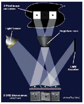
8 By electrically addressing the memory cell below each mirror with the binary bit plane signal, each mirror on the DMD array is electrostatically tilted to the on or off positions. The technique that determines how long each mirror tilts in either direction is called pulse width modulation (PWM). The mirrors are capable of switching on and off more than 1000 times a second. This rapid speed allows digital gray scale and color reproduction. At this point, DLP becomes a simple optical system. After passing through condensing optics and a color filter system, the light from the projection lamp is directed at the DMD. When the mirrors are in the on position, they reflect light through the projection lens and onto the screen to form a digital, square-pixel projected image (figure shown in the next page). Three mirrors efficiently reflect light to project a digital image. Incoming light hits the three mirror pixels. The two outer mirrors that are turned on reflect the light through the projection lens and onto the screen. These two "on" mirrors produce square, white pixel images. The central mirror is tilted to the "off" position. This mirror reflects light away from the projection lens to a light absorber so no light reaches the screen at that particular pixel, producing a square, dark pixel image In the same way, the remaining 508,797 mirror pixels reflect light to the screen or away from it. By using a color filter system and by varying the amount of time each of the 508,800 DMD mirror pixels is on, a full-color, digital picture is projected onto the screen. 7
9 8
10 GRAYSCALE AND COLOR OPERATION Grayscale is achieved by binary pulse width modulation of the incident light. Color is achieved by using color filters, either stationary or rotating, in combination with one, two, or three DMD chips. The DMD light switch is able to turn light on and off rapidly by the beam-steering action of the mirror. As the mirror rotates, it either reflects light into or out of the pupil of the projection lens, to create a burst of digital light pulses that the eye interprets as an analog image. The optical switching time for the DMD light switch is ~2 µs. The mechanical switching time, including the time for the mirror to settle and latch, is ~15 µs [36]. The technique for producing the sensation of grayscale to the observer s eye is called binary pulse width modulation. The DMD accepts electrical words representing gray levels of brightness at its input and outputs optical words, which are interpreted by the eye of the observer as analog brightness levels. The details of the binary pulse width modulation (PWM) technique are illustrated in Figure 7. For simplicity, the PWM technique is illustrated for a 4-bit word (2 4 or 16 gray levels). 9
 is called the least significant bit (LSB). The longest interval (8) is called the most significant bit (MSB).")
11 Each bit in the word represents time duration for light to be on or off (1 or 0). The time durations have relative values of 2 0, 2 1, 2 2, 2 3, or 1, 2, 4, 8. The shortest interval (1) is called the least significant bit (LSB). The longest interval (8) is called the most significant bit (MSB). The video field time is divided into four time durations of 1/15, 2/15, 4/15, and 8/15 of the video field time. The possible gray levels produced by all combinations of bits in the 4-bit word are 2 4 or 16 equally spaced gray levels (0, 1/15, 2/ /15). Current DLP systems are either 24-bit color (8 bits or 256 gray levels per primary color) or 30-bit color (10 bits or 1024 gray levels per primary color). In the simple example shown in Figure 7, spatial and temporal artifacts can be produced because of imperfect integration of the pulsed light by the viewer s eye. These artifacts can be reduced to negligible levels by a bit-splitting technique. In this technique, the longer duration bits are subdivided into shorter durations, and these split bits are distributed through-out the video field time. DLP displays combine pulse width modulation and bit-splitting to produce a true-analog sensation, but with greater accuracy and stability than can be achieved by analog projection systems. 10

12 DMD CELL ARCHITECTURE AND FABRICATION The DMD pixel is a monolithically integrated MEMS super-structure cell fabricated over a CMOS SRAM cell (Figure 8). An organic sacrificial layer is removed by plasma etching to produce air gaps between the metal layers of the superstructure. The air gaps free the structure to rotate about two compliant torsion hinges. The mirror is rigidly connected to an underlying yoke. The yoke, in turn, is connected by two thin, mechanically compliant torsion hinges to support posts that are attached to the underlying substrate. The address electrodes for the mirror and yoke are connected to the complementary sides of the underlying 11
13 SRAM cell. The yoke and mirror are connected to a bias bus fabricated at the metal-3 layer. The bias bus interconnects the yoke and mirrors of each pixel to a bond pad at the chip perimeter. An off-chip driver supplies the bias waveform necessary for proper digital operation. The DMD mirrors are 16 µm square and made of aluminum for maximum reflectivity. They are arrayed on 17 µm centers to form a matrix having a high fill factor (~90%). The high fill factor produces high efficiency for light use at the pixel level and a seamless (pixelation-free) projected image. Electrostatic fields are developed between the mirror and its address electrode and the yoke and its address electrode, creating an efficient electrostatic torque. This torque works against the restoring torque of the hinges to produce mirror and yoke rotation in the positive or negative direction. The mirror and yoke rotate until the yoke comes to rest (or lands) against mechanical stops that are at the same potential as the yoke. Because geometry determines the rotation angle, as opposed to a balance of electrostatic torques employed in earlier analog devices, the rotation angle is precisely determined. The fabrication of the DMD superstructure begins with a completed CMOS memory circuit. A thick oxide is deposited over metal-2 of the CMOS and then planarized using a chemical mechanical polish (CMP) technique. The CMP step provides a completely flat substrate for DMD superstructure fabrication, ensuring that the projector s brightness uniformity and contrast ratio are not degraded. 12
 that form the two air gaps. The aluminum is sputter-deposited and plasma-etched using plasma-deposited SiO2 as the etch mask.")
14 Through the use of six photomask layers, the superstructure is formed with layers of aluminum for the address electrode (metal- 3), hinge, yoke and mirror layers and hardened photo-resist for the sacrificial layers (spacer-1 and spacer-2) that form the two air gaps. The aluminum is sputter-deposited and plasma-etched using plasma-deposited SiO2 as the etch mask. Later in the packaging flow, the sacrificial layers are plasma-ashed to form the air gaps. The packaging flow begins with the wafers partially sawed along the chip scribe lines to a depth that will allow the chips to be easily broken apart later. The partially sawed and cleaned wafers then proceed to a plasma etcher that is used to selectively strip the organic sacrificial layers from under the DMD mirror, yoke, and hinges. Following this process, a thin lubrication layer is deposited to prevent the landing tips of the yoke from adhering to the landing pads during operation. Before separating the chips from one another, each chip is tested for full electrical and optical functionality by a high-speed automated wafer tester. Finally, the chips are separated from the wafer, plasma-cleaned, relubricated, and hermetically sealed in a package. Figure 9 shows a packaged DMD chip. 13
15 An 848 x 600 Digital Micro mirror Device. The central, reflective portion of the device consists of 508,800 tiny, tilt able mirrors. A glass window seals and protects the mirrors. 14
16 ELECTRONIC OPERATION The DMD pixel is inherently digital because of the way it is electronically driven. It is operated in an electro statically bistable mode by the application of a bias voltage to the mirror to minimize the address voltage requirements. Thus, large rotation angles can be achieved with a conventional 5-volt CMOS address circuit. The pulse width modulation scheme for the DMD requires that the video field time be divided into binary time intervals or bit times. During each bit time, while the mirrors of the array are modulating light, the underlying memory array is refreshed or updated for the next bit time. Once the memory array has been updated, all the mirrors in the array are released simultaneously and allowed to move to their new address states. This simultaneous update of all mirrors, when coupled with the PWM bit-splitting algorithm produces an inherently lowflicker display. Flicker is the visual artifact that can be produced in CRTs as a result of brightness decay with time of the phosphor. Because CRTs are refreshed in an interlaced scan-line format, there is both a line-to-line temporal phase shift in brightness as well as an overall decay in brightness. DLP-based displays have inherently low flicker because all pixels are updated at the same time (there is no line-to-line temporal phase shift) and because the 15
17 PWM bit-splitting algorithm produces short-duration light pulses that are uniformly distributed throughout the video field time (no temporal decay in brightness). Proper operation of the DMD is achieved by using the bias and address sequence shown in Figure 11 and detailed in Table 1. Table 1. DMD address and reset sequence 1. Memory ready All memory cells under the DMD have been loaded with the new address states for the mirrors. 2. Reset All mirrors are reset in parallel (voltage pulse applied to bias bus). 3. Unlatch The bias is turned off to unlatch mirrors and allow them to release and begin to rotate to flat state. 4. Differentiate Retarding fields are applied to the yoke and mirrors in order to rotationally separate the mirrors that remain in the same state from those that are to cross over to a new state. 16
18 5. Land and latch The bias is turned on to capture the rotationally separated mirrors and enable them to rotate to the addressed states, then settle and latch. 6. Update memory array (one line at a time) The bias remains turned on to keep the mirrors latched so as to prevent them from responding to changes in the memory, while the memory is written with new video data. 7. Repeat sequence beginning at step 1. The bias voltage has three functions. First, it produces a bistable condition to minimize the address voltage requirement, as previously mentioned. In this manner, large rotation angles can be achieved with conventional 5-volt CMOS. Second, it electromechanically latches the mirrors so that they cannot respond to changes in the address voltage until the mirrors are reset. The third function of the bias is to reset the pixels so that they can reliably break free of surface adhesive forces and begin to rotate to their new address states. Although the metal surfaces of the superstructure are coated with a passivation layer or lubrication layer, the remaining Van der Waal or surface forces between molecules require more than the hinge-restoring force to reliably reset the mirrors. A reset voltage pulse applied to the mirror and yoke causes the spring tips of the yoke (Figure 12) to flex. 17

19 As the spring tips unflex, they produce a reaction force that causes the yoke landing tips to accelerate away from the landing pads, producing a reliable release from the surface. 18
20 DLP SYSTEM DESCRIPTION AND OPERATION Figure 13 illustrates a generic three-chip DLP system broken down into its functional components (video front-end, digital processor, digital formatter, and digital display). The generic video front-end accepts a variety of video sources (digital, digital compressed, digital graphics, analog composite, analog s- video, and analog graphics). The video front-end performs the functions of decompression, decoding, and analog-to-digital conversion, depending on the nature of the video source. The first operation in the digital processor is progressive-scan conversion. This conversion is required if the original source material is interlaced. An interlaced format provides even lines of video during one video field time and odd 19
21 lines during the next field time. Progressive-scan conversion is the process of creating (by an interpolation algorithm) new scan lines between the odd or even lines of each video field. Interlacing has been historically used in CRT-based systems to reduce the video bandwidth requirements without producing objectionable flicker effects created by the temporal decay in phosphor brightness. For progressively scanned CRTs, interlacing is unnecessary because additional bandwidth is allocated so that every line of the CRT is refreshed during each field time. Progressive scanning that incorporates motion-adaptive algorithms helps to reduce interlace scanning artifacts such as interline flicker, raster line visibility, and field flicker. These are particularly noticeable in larger display formats. The next operation in the digital processor is digital resampling (or scaling). This operation resizes the video data to fit the DMD s pixel array, expands letterbox video sources, and maintains a correct aspect ratio for the square pixel DMD format. After the scaling operation, the video data is input to the color space conversion block. If the video is not already in a red, green, blue (R, G, B) format, it is converted from luminance and color difference encoding (e.g., Y, CR, CB) into R, G, B. Next, a degamma (inverse gamma) function is per-formed.crt systems have non-linear signal-to-light characteristics. Inorder to compensate for this error, an error correction, called Gamma correction is done on images. But as the DLP system has linear signal-to-light characteristics, this correction is to be removed, 20
22 which is done in the degamma section. The degamma operation can produce low-light-level contouring effects, but these are minimized by using an error diffusion technique. Finally the R, G, B signal is input to the digital formatter. First, the scan-line format data is converted into an R, G, B bit-plane format. The bit planes are stored in a dualsynchronous DRAM (SDRAM) frame buffer for fast access of the bit-plane data. The bit-plane data is then output to the DMDs in a PWM bit-splitting sequence. The DMD chip has multiple data inputs that allow it to match the frequency capability of the onchip CMOS with the required video data rates. The bit-plane data coming out of the frame buffer is multiplexed 16:1 and fed to the multiple data inputs of each DMD. The bit-plane data is then demultiplexed 1:16 and fed to the frame-memory underlying the DMD pixel array. 21

23 PROJECTION OPTICS DLP optical systems have been designed in a variety of con-figurations distinguished by the number of DMD chips (one, two, or three) in the system. The one-chip and two-chip systems rely on a rotating color disk to time-multiplex the colors. The onechip configuration is used for lower brightness applications and is the most compact. Two-chip systems yield higher brightness performance but are primarily intended to compensate for the color deficiencies resulting from spectrally imbalanced lamps (e.g., the red deficiency in many metal halide lamps). For the highest brightness applications, three-chip systems are required. A DLP optical system with three chips is shown in Figure 14. Because the DMD is a simple array of reflective light switches, no polarizers are required. Light from a metal halide or xenon lamp is collected by a condenser lens. For proper operation of the DMD light switch, this light must be directed at 20 degrees 22
 prism is interposed between the projection")
24 relative to the normal of the DMD chip (Figure 6). To accomplish this in a method that eliminates mechanical interference between the illuminating and projecting optics, a total internal reflection (TIR) prism is interposed between the projection lens and the DMD color-splitting/-combining prisms. The color-splitting/-combining prisms use dichroic interference filters deposited on their surfaces to split the light by reflection and transmission into red, green, and blue components. The red and blue prisms require an additional reflection from a TIR surface of the prism in order to direct the light at the correct angle to the red and blue DMDs. Light reflected from the on-state mirrors of the three DMDs is directed back through the prisms and the color components are recombined. The combined light then passes through the TIR prism and into the projection lens because its angle has been reduced below the critical angle for total internal reflection in the prism air gap. 23
25 A DLP three-chip prototype projection engine is shown in Figure 15. It projects 1100 lumens with a 500-watt xenon lamp. The size of the engine is in. and it weighs 38 pounds. One of the DMD package assemblies with thermoelectric cooler and fan is visible. 24
26 TECHNOLOGICAL ADVANTAGES 1. The Digital Advantage The audio world started the trend toward digital technology well over a decade ago. Recently, an abundance of new digital video technology has been introduced to the entertainment and communications markets. The digital satellite system (DSS) quickly became the fastest selling consumer electronics product of all time, selling record numbers of units in its first year of introduction. Sony, JVC, and Panasonic have all recently introduced digital camcorders. Epson, Kodak, and Apple are a few of the companies that now have digital cameras on the market. The digital versatile disc (DVD), a widely anticipated new storage medium, will feature full-length films with better than laser disc video quality by placing up to 17 gigabytes of information on a single disc. Today we have the ability to capture, edit, broadcast, and receive digital information, only to have it converted to an analog signal just before it is displayed. DLP has the ability to complete the final link to a digital video infrastructure as well as to provide a platform on which to develop a digital visual communications environment. Each time a signal is converted from digital to analog (D/A) or analog to digital (A/D), signal noise enters the data path. Fewer conversions translates to lower noise and leads to 25
. The video infrastructure.")
27 lower cost as the number of A/D and D/A converters decreases. DLP offers a scalable projection solution for displaying a digital signal, thus completing an all-digital infrastructure (figure shown below). The video infrastructure. DLP offers the final link to a complete digital video infrastructure. Another digital advantage is DLP s accurate reproduction of gray scale and color levels. And because each video or graphics frame is generated by a digital, 8- to 10-bits-percolor gray scale, the exact digital picture can be recreated time and time again. For example, an 8-bits-per-color gray scale gives 256 different shades of each of the primary colors, which allows for 256³, or 16.7 million, different color combinations that can be digitally created (Figure shown below). 26

28 DLP can generate digital gray scale and color levels. Assuming 8 bits per color, 16.7 million digitally created color combinations are possible. Above are several combinations of different gray scale levels for each of the primary colors and the resultant digitally created pixel colors. 2. The Reflective Advantage Because the DMD is a reflective device, it has a light efficiency of greater than 60%, making DLP systems more efficient than LCD projection displays. This efficiency is the product of reflectivity, fill factor, diffraction efficiency, and actual mirror "on" time. LCDs are polarization-dependent, so one of the polarized light components is not used. This means that 50% of 27

29 the lamp light never even gets to the LCD because it is filtered out by a polarizer. Other light is blocked by the transistors, gate, and source lines in the LCD cell. In addition to these light losses, the liquid crystal material itself absorbs a portion of the light. The result is that only a small amount of the incident light is transmitted through the LCD panel and onto the screen. Recently, LCDs have experienced advances in apertures and light transmission, but their performance is still limited because of their dependence on polarized light. 3. Seamless Picture Advantage The square mirrors on DMDs are 16 µm², separated by 1 µm gaps, giving a fill factor of up to 90%. In other words, 90% of the pixel/mirror area can actively reflect light to create a projected image. Pixel size and gap uniformity are maintained over the entire array and are independent of resolution. LCDs have, at best, a 70% fill factor. The higher DMD fill factor gives a higher perceived resolution, and this, combined with the progressive scanning, creates a projected image that is much more natural and lifelike than conventional projection displays (Figure 18),(Figure19a), (Figure19b). Fig.18 28
 LCD projector was used to project the image of the parrot shown in Figure18.")
30 Photograph used to demonstrate the DLP advantage. This digitized photograph of a parrot was used to demonstrate the seamless, filmlike DLP picture advantage detailed in Figures19a and b. A leading video graphics adapter (VGA) LCD projector was used to project the image of the parrot shown in Figure18. In Figure19a, the pixelated, screen-door effect common to LCD projectors can easily be seen. The same image of the parrot was projected using a DLP projector and is displayed in Figure 19b. Because of the high fill factor of DLP, the screen-door effect is gone. What is seen is a digitally projected image made up of square pixels of information. With DLP, the human eye sees more visual information and perceives higher resolution, although, as demonstrated, the actual resolution shown in both projected images is the same. As the photographs illustrate, DLP offers compellingly superior picture quality. Fig.19a Fig.19b Figure19. Actual close-up photographs of both (a) an LCDprojected image and (b) a DLP -projected image. A three-panel polysilicon VGA resolution LCD projector (a) and a one-chip VGA resolution DLP projector (b) both project the photograph of 29
31 the parrot shown in Figure 18. Both the LCD and DLP photos were taken under the same conditions, with each projector being optimized for focus, brightness, and color. Note the high level of pixelation in the LCD image in contrast to the seamless DLP image. DLP offers superior picture quality because the DMD mirror pixels are separated by only 1 µ thus eliminating pixelation. 30
32 BENEFITS 1. Clarity- As it is already explained, the DLP system provides high clarity images due to its improved digital technology. 2. Better Resolution-As the mirrors are very closely packed to give high fill factor of 90%. This high fill factor gives a higher perceived resolution which results in much more natural and lifelike projected image. 3. Maximum brightness-at high luminous flux densities (lumens/cm2), optical absorption creates heating effects. Excessive temperature can cause degradation of performance for both LCDs and DMDs. In the case of LCDs, excessive heating causes degradation of the polarizers. Furthermore, without adequate cooling of the LCD panel, the temperature of the LCD material can rise above its clearing temperature Tc. This renders the LCD material useless for polarization rotation and the display fails. For transmissive AM-LCD panels, a heatsink cannot be attached to the substrate, so forced air cooling must be relied upon. Larger transmissive panels mitigate this problem. Currently, AM-LCD projectors having 3000-lumen outputs use in. panels. Excessive temperatures can also affect the long-term reliability of the DMD by accelerating hinge deformation (metal 31
33 creep) that can occur under high-duty-factor operation of the mirror. Special hinge alloys have been developed to minimize this deformation and guarantee reliable operation. High duty factors occur when the mirror is operated in one direction for a much greater part of the time, on average, than in the other direction. For example, 95/5 duty factor operation means that a mirror is 95% of the time at one rotation angle (e.g., -10 degrees) and 5% of the time at the other rotation angle (e.g., +10 degrees). This situation would correspond to DMD operation with a video source having a temporal average brightness of 5% (or 95%) of the peak brightness. Although these extreme temporal averages are unlikely to occur for extended periods of time, 95/5 duty factor is chosen as a worst case reliability test condition for hinge deformation. With current hinge metal alloys, long-term, reliable DMD operation at the 95/5 duty factor is assured, provided the operating temperature of the hinge is limited to <65 C. For high-brightness applications, the mirrors can absorb enough energy to raise the hinge temperature above 65 C unless active cooling is applied to the package. Because the DMD is reflective and built on a single-crystal silicon (X-silicon) backplane, the absorbed heat can be efficiently extracted by connecting a thermoelectric cooler (TEC) to the backside of the DMD package. In Figure 15, one of the DMD package assemblies with the thermoelectric cooler is visible. The DMD package contains a thermal via to provide a low-thermal- impedance path between the DMD chip and the TEC. A thermal model predicts that for a three-chip SXGA projector producing 10,000 32
34 screen lumens, the hinge temperature can be held to <65 C (with TEC cooling and an internal ambient air temperature of 55 C). 4. Brightness Uniformity-Brightness uniformity is also an important part of image quality. Uniformity represents the percentage of brightness carried throughout a projected image. A higher uniformity percentage indicates that the projector delivers brightness more evenly from center to the corners of the projected image, eliminating hot spots and di8stortion.dlp system has got a brightness uniformity of more than 85%. 5. Low flicker effect-flicker is the visual articraft that can be produced in CRTs as a result of brightness decay with time. Usually in scatter scanning technique, the lines in the video frames are scanned sequentially. So at a particular instant of a time different points on the screen will have different brightness levels. This will give rise to flicker. But in DLP, all the mirror pixels are updated in parallel at the same time. This minimizes the flicker. 6. Life like color -as already seen the digital technology will give lifelike color and makes it possible to display 16.7 million different color combinations on the screen at a time. 7. Contrast ratio-contrast ratio is the difference between the lightest and the darkest portions of an image. The larger the contrast ratio, the greater the ability of a projector to show subtle color details and tolerate a room s ambient light. The inherent 33
35 contrast ratio of the DMD is determined by measuring the ratio of the light flux with all pixels turned on versus the flux with all pixels turned off. The system contrast ratio is determined by measuring the light flux ratio between bright and dark portions of a 4 4 checkerboard image according to ANSI specifications. The checkerboard measurement takes into account light scatter and reflections in the lens, which can degrade the inherent contrast ratio of the DMD. The full on/off contrast ratio determines the dark level for scenes having a low average luminance level (e.g., outdoor night scenes) as well as the video black level. The checker-board contrast ratio is a measure of the contrast for objects in scenes containing a full range of luminance levels. The inherent contrast ratio of the DMD is limited by light diffraction from the mirror edges, from the underlying substrate, and from the mirror via (the metallized hole in the middle of the mirror that acts as the mirror support post, as shown in Figure 4). Recent architectural improvements to the DMD pixels have led to improved contrast ratios. 8. Portability-Because of its very low size and weight, DLP projector system is higly portable. A projector giving an output of 2000 lumens weigh only 6.6 pounds and that giving 1000 lumens, which is called as the micro projector weighs only 2 pounds. 34
36 9. Accuracy and Stability-Current high-brightness projection displays for use in the audio/visual rental and staging business and for private and corporate use have a number of limitations. These include warm-up or stabilization time; setup time for convergence, color balance, and gamma; and, finally, the stability of the image quality once the system is operating. Maintaining stability over a wide range of environmental conditions encountered in outdoor applications is particularly difficult. For video wall applications or other applications requiring multiple side-by-side projectors, the setup time to make the entire displays look identical is often unacceptable. Even when great care has been taken in this procedure, lack of stability makes periodic adjustments necessary. DLP-based projection systems offer the potential of short setup time and stable, adjustment-free images. Initial stabilization time is minimal. The working is also very fast. This is because of the fact that the optical switching time of the mirror is only 2us and the mechanical switching time including the time for the mirror to settle and latch is only 15 us. Convergence is fixed by internal alignment of the three DMDs and is stable with time and in-dependent of throw distance. Color balance, uniformity, and gamma are digitally controlled by Pulse Width Modulation and are not affected by temperature. Brightness roll off is stable (fixed by a light integrator) and can be made small to accommodate video wall applications. 35

37 DMD Reliability Steady improvements in DMD reliability have been made. Some of these are listed below: An improved hinge material that reduces metal creep that can occur under high-duty-factor and high-temperature operating conditions. The hinge material is manufactured using thin-film technology to get less stiff material. Improved packaging techniques that preserve the lubricity of the landing surface over a wide range of environmental conditions. A new architecture that incorporates spring tips at the landing tip of the yoke. These springs store energy upon landing and push the mirror away from the surface upon release. The result is greater operating margins as the yoke releases (resets) from the underlying surface. The picture of this spring structure is shown below. 36
38 A particle reduction program that has dramatically reduced particle contamination within the DMD package. The DMD has passed a series of tests to simulate actual DMD environmental operating conditions, including thermal shock, temperature cycling, moisture resistance, mechanical shock, vibration, and acceleration testing and has passed all of these tests. In addition to these, other tests have been conducted to determine the long-term result of repeated cycling of mirrors between the on and off states. Mirror cycling tests look for hinge fatigue (broken hinges) and failure of the mirrors to release because of increased adhesion (reset failure). To date, in accelerated tests, a lifetime of more than 765 billion cycles has been demonstrated (equivalent lifetime >76,000 hours ie, approximately 20 years of reliable operation) for a 10-bit/primary color, three-chip projector configuration). 37
39 DLP BRAND PRODUCTS Texas Instruments is teamed with numerous projection display manufacturers spanning -Business (conference room), -Consumer (home theater), and -Professional (high-brightness) markets. DLP brand products and prototypes serving all three market segments have been demonstrated at numerous trade shows including Cedia, Comdex, CES, Infocomm, EID, IFA, JES, Photokina, Photonics West, SID, and Satis. Currently, Digital Projection Ltd., Electrohome, and Sony are developing high-brightness DLP brand products with SVGA resolution and brightness levels ranging from 1100 lumens to 3000 lumens. 38
40 CONCLUSION DLP brand projection displays are well-suited to highbrightness and high-resolution applications. The digital light switch is reflective and has a high fill factor that results in high optical efficiency at the pixel level and low pixelation effects in the projected image. The DMD family of chips uses a common pixel design and a monolithic CMOS-like process. These factors, taken together, mean that scaling to higher resolutions is straightforward, without loss of pixel optical efficiency. At higher resolutions, the DLP brand projector becomes even more efficient in its use of light because of higher lampcoupling efficiency. Because the DMD is a reflective technology, the DMD chip can be effectively cooled through the chip substrate, thus facilitating the use of high-power projection lamps without thermal degradation of the DMD. DLP brand systems are all-digital (digital video in, digital light out) that give accurate, stable reproduction of the original source material. This single digital light display system is obviously going to be the technology of future revolutionizing the field of video display technology providing high clarity, high-resolution, high-brightness seamless images. 39
41 REFERENCES glossary 3. for High-Brightness, High-Resolution Applications - L.J.Hornbeck, Texas Instruments Ltd 4. Introduction to DLP Technology - Lars a. Yoder Texas Instruments Ltd 5. Video Processing for DLP System - Vishal & Todd, Digital Video Product Texas Instruments Ltd 40
42 ABSTRACT Electronic projection display technologies for high brightness applications, from the initial Gretag Eidophor, an oil based projection, to solid state technology based LCD systems, are all analog devices having many disadvantages. All the products of this information age, digital cameras, digital concoders, digital satellite system, DVDs, play source material of unprecented image quality and so does the Internet-the seemingly endless forum of digitized information. The whole exercise of preserving digital video and graphic data would be pointless if it has to be converted to analog before viewing. Texas Instruments' technology-the only available digital display technology is a revolutionary alternative. At the heart of the DLP display is the Digital Micromirror device (DMD), a semiconductor based array of fast, reflective digital light switches. Digital electronics and optics converge at DMD. Based on this DMD, DLP can form the final link to digital visual communication. In the same way the compact disc revolutionized the audio industry, DLP will revolutionize video projection. This seminar describes the design, operation, performance and advantages of DLP based projection system for high brightness, high resolution application. 41
43 42
Digital Light Processing
 A Seminar report On Digital Light Processing Submitted in partial fulfillment of the requirement for the award of degree of Bachelor of Technology in Computer Science SUBMITTED TO: www.studymafia.org SUBMITTED
DVR & Dr.HS MIC College Of Technology KANCHIKACHERLA.
 Presented by, K.Santosh reddy E.D.A.Sasikanth Santoshreddy1988@gmail.com sasikanth_kinng@yahoo.co.in (III/IV B.Tech.) (III/IV B.Tech.) Ph: 9491753338 Ph: 9885017636 Dept. of Electronics and Communications
An Overview of the Performance Envelope of Digital Micromirror Device (DMD) Based Projection Display Systems
 Based Projection Display Systems") An Overview of the Performance Envelope of Digital Micromirror Device (DMD) Based Projection Display Systems Dr. Jeffrey B. Sampsell Texas Instruments Digital projection display systems based on the DMD
An Overview of the Performance Envelope of Digital Micromirror Device (DMD) Based Projection Display Systems Dr. Jeffrey B. Sampsell Texas Instruments Digital projection display systems based on the DMD
An Alternative Architecture for High Performance Display R. W. Corrigan, B. R. Lang, D.A. LeHoty, P.A. Alioshin Silicon Light Machines, Sunnyvale, CA
 R. W. Corrigan, B. R. Lang, D.A. LeHoty, P.A. Alioshin Silicon Light Machines, Sunnyvale, CA Abstract The Grating Light Valve (GLV ) technology is being used in an innovative system architecture to create
Digital High Resolution Display Technology. A New Way of Seeing Things.
 R Digital High Resolution Display Technology A New Way of Seeing Things. Raytheon s Digital Display Digital Light Processing (DLP ) by Texas Instruments is a revolutionary new way to project and display
Digital Light Processing : A New MEMS-Based Display Technology. Larry J. Hornbeck Texas Instruments. 1.0 Introduction
 Section 1.0 Introduction Section 2.0 DMD Architechture Section 3.0 Projection Operation Section 4.0 Fabrication Section 5.0 Reliability Section 6.0 DLP Business Opportunities Section 7.0 Summary Section
These are used for producing a narrow and sharply focus beam of electrons.
 CATHOD RAY TUBE (CRT) A CRT is an electronic tube designed to display electrical data. The basic CRT consists of four major components. 1. Electron Gun 2. Focussing & Accelerating Anodes 3. Horizontal
Dynamic IR Scene Projector Based Upon the Digital Micromirror Device
 Dynamic IR Scene Projector Based Upon the Digital Micromirror Device D. Brett Beasley, Matt Bender, Jay Crosby, Tim Messer, and Daniel A. Saylor Optical Sciences Corporation www.opticalsciences.com P.O.
Display Technologies CMSC 435. Slides based on Dr. Luebke s slides
 Display Technologies CMSC 435 Slides based on Dr. Luebke s slides Recap: Transforms Basic 2D Transforms: Scaling, Shearing, Rotation, Reflection, Composition of 2D Transforms Basic 3D Transforms: Rotation,
Overview of All Pixel Circuits for Active Matrix Organic Light Emitting Diode (AMOLED)
") Chapter 2 Overview of All Pixel Circuits for Active Matrix Organic Light Emitting Diode (AMOLED) ---------------------------------------------------------------------------------------------------------------
Chapter 2 Overview of All Pixel Circuits for Active Matrix Organic Light Emitting Diode (AMOLED) ---------------------------------------------------------------------------------------------------------------
Pressure sensor. Surface Micromachining. Residual stress gradients. Class of clean rooms. Clean Room. Surface micromachining
 Pressure sensor Surface Micromachining Deposit sacrificial layer Si PSG By HF Poly by XeF2 Pattern anchors Deposit/pattern structural layer Etch sacrificial layer Surface micromachining Structure sacrificial
Development of Simple-Matrix LCD Module for Motion Picture
 Development of Simple-Matrix LCD Module for Motion Picture Kunihiko Yamamoto* Shinya Takahashi* Kouki Taniguchi* * A1203 Project Team Abstract A simple-matrix LCD module (12.1-in. SVGA) has been developed
Digital Light Processing
 Digital Light Processing Prof. Rahul R. Ambalkar Asst. Prof Depart of EXTC ambalkar.rahul@gmail.com Mr. Suraj Datta Ghodge EXTC Dept. Final year student. surajghodge1994@gmail.com Miss. Alka Prakash Morey
Projection Displays Second Edition
 Projection Displays Second Edition by Matthew S. Brennesholtz Insight Media, USA Edward H. Stupp Stupp Associates, USA WILEY A John Wiley and Sons, Ltd, Publication Contents Foreword Preface to the Second
Liquid Crystal Display (LCD)
") Liquid Crystal Display (LCD) When coming into contact with grooved surface in a fixed direction, liquid crystal molecules line up parallelly along the grooves. When coming into contact with grooved surface
Liquid Crystal Display (LCD) When coming into contact with grooved surface in a fixed direction, liquid crystal molecules line up parallelly along the grooves. When coming into contact with grooved surface
How to Match the Color Brightness of Automotive TFT-LCD Panels
 Relative Luminance How to Match the Color Brightness of Automotive TFT-LCD Panels Introduction The need for gamma correction originated with the invention of CRT TV displays. The CRT uses an electron beam
PROFESSIONAL D-ILA PROJECTOR DLA-G11
 PROFESSIONAL D-ILA PROJECTOR DLA-G11 A new digital projector that projects true S-XGA images with breakthrough D-ILA technology Large-size projection images with all the sharpness and clarity of a small-screen
Types of CRT Display Devices. DVST-Direct View Storage Tube
 Examples of Computer Graphics Devices: CRT, EGA(Enhanced Graphic Adapter)/CGA/VGA/SVGA monitors, plotters, data matrix, laser printers, Films, flat panel devices, Video Digitizers, scanners, LCD Panels,
Solid State Devices 4B6
 Solid State Devices 4B6 Lecture 13 Projection and 3D displays: LCD, DLP and LCOS Daping Chu Lent 2016 Development of flat panel displays (FPDs) (LCD) in early days 1 A 105 inch TFT-LCD 4k2k curved panel
OverView D. Barco DLP projection series
 OverView D Barco DLP projection series Based upon years of experience and focused development, Barco Control Rooms has developed the ultimate display wall for the control room environment. The OVERVIEW
D-ILA PROJECTOR DLA-G15 DLA-S15
 D-ILA PROJECTOR DLA-G15 Outstanding Projection Im Breakthrough D-ILA projector offers high-contrast 350:1, 1500 ANSI lumen brightness and S-XGA resolution Large-size projection images with all the sharpness
PROFESSIONAL D-ILA PROJECTOR DLA-G11
 PROFESSIONAL D-ILA PROJECTOR DLA-G11 A new digital projector that projects true S-XGA images with breakthrough D-ILA technology Large-size projection images with all the sharpness and clarity of a small-screen
COPYRIGHTED MATERIAL. Introduction. 1.1 Overview of Projection Displays
 1 Introduction 1.1 Overview of Projection Displays An electronic display is a device or system which converts electronic signal information representing video, graphics and/or text to a viewable image
DLP Discovery Reliability Application Note
 Data Sheet TI DN 2510330 Rev A March 2009 DLP Discovery Reliability Application Note May not be reproduced without permission from Texas Instruments Incorporated IMPORTANT NOTICE BEFORE USING TECHNICAL
Flat Panel Displays: LCD Technologies and Trends
 Flat Panel Displays: LCD Technologies and Trends Robert Dunhouse, Sr. Engineering Manager, Display BU Class ID: 4C01B Renesas Electronics America Inc. Robert F. Dunhouse, Jr. Sr. Engineering Manager, Display
LEDs an der Schwelle zum Einsatz in Projektionssystemen: Herausforderungen, Grenzen und Anwendungen
 LEDs an der Schwelle zum Einsatz in Projektionssystemen: Herausforderungen, Grenzen und Anwendungen Dr. Anton Moffat Carl Zeiss Corporate Research Carl Zeiss AG, Jena, Germany moffat@zeiss.de Contents
Lecture Flat Panel Display Devices
 Lecture 1 6.976 Flat Panel Display Devices Outline Overview of 6.976 Overview Flat Panel Display Devices Course website http://hackman.mit.edu Reading Assignment: Article by Alt and Noda, IBM Journal of
Optical Engine Reference Design for DLP3010 Digital Micromirror Device
 Application Report Optical Engine Reference Design for DLP3010 Digital Micromirror Device Zhongyan Sheng ABSTRACT This application note provides a reference design for an optical engine. The design features
SPATIAL LIGHT MODULATORS
 SPATIAL LIGHT MODULATORS Reflective XY Series Phase and Amplitude 512x512 A spatial light modulator (SLM) is an electrically programmable device that modulates light according to a fixed spatial (pixel)
ID C10C: Flat Panel Display Basics
 ID C10C: Flat Panel Display Basics Renesas Electronics America Inc. Robert Dunhouse, Display BU Engineering Manager 12 October 2010 Revision 1.1 Robert F. Dunhouse, Jr. Displays Applications Engineering
CPD LED Course Notes. LED Technology, Lifetime, Efficiency and Comparison
 CPD LED Course Notes LED Technology, Lifetime, Efficiency and Comparison LED SPECIFICATION OVERVIEW Not all LED s are alike During Binning the higher the flux and lower the forward voltage the more efficient
THE challenges facing today s mobile
 MEMS displays MEMS-Based Display Technology Drives Next-Generation FPDs for Mobile Applications Today, manufacturers of mobile electronic devices are faced with a number of competitive challenges. To remain
PRODUCT GUIDE CEL5500 LIGHT ENGINE. World Leader in DLP Light Exploration. A TyRex Technology Family Company
 A TyRex Technology Family Company CEL5500 LIGHT ENGINE PRODUCT GUIDE World Leader in DLP Light Exploration Digital Light Innovations (512) 617-4700 dlinnovations.com CEL5500 Light Engine The CEL5500 Compact
Guide to designing a device incorporating MEMSbased pico projection
 Guide to designing a device incorporating MEMSbased pico projection By Carlos Lopez MEMS technology shown enabling a near eye display application Over the last few years, millions of products incorporating
High Performance TFT LCD Driver ICs for Large-Size Displays
 Name: Eugenie Ip Title: Technical Marketing Engineer Company: Solomon Systech Limited www.solomon-systech.com The TFT LCD market has rapidly evolved in the last decade, enabling the occurrence of large
D-ILA PROJECTOR DLA-G15 DLA-S15
 D-ILA PROJECTOR Outstanding Projection Im Breakthrough D-ILA projector offers high-contrast 350:1, 1500 ANSI lumen brightness and S-XGA resolution Large-size projection images with all the sharpness and
 Chapter 3 Evaluated Results of Conventional Pixel Circuit, Other Compensation Circuits and Proposed Pixel Circuits for Active Matrix Organic Light Emitting Diodes (AMOLEDs) -------------------------------------------------------------------------------------------------------
High performance optical blending solutions
 High performance optical blending solutions WHY OPTICAL BLENDING? Essentially it is all about preservation of display dynamic range. Where projected images overlap in a multi-projector display, common
Lecture Flat Panel Display Devices
 Lecture 13 6.111 Flat Panel Display Devices Outline Overview Flat Panel Display Devices How do Displays Work? Emissive Displays Light Valve Displays Display Drivers Addressing Schemes Display Timing Generator
21 rue La Noue Bras de Fer Nantes - France Phone : +33 (0) website :
 website :") 21 rue La Noue Bras de Fer - 44200 Nantes - France Phone : +33 (0) 240 180 916 - email : info@systemplus.fr - website : www.systemplus.fr 2012 September - Version 1 Written by: Maher Sahmimi DISCLAIMER
21 rue La Noue Bras de Fer - 44200 Nantes - France Phone : +33 (0) 240 180 916 - email : info@systemplus.fr - website : www.systemplus.fr 2012 September - Version 1 Written by: Maher Sahmimi DISCLAIMER
CCD Element Linear Image Sensor CCD Element Line Scan Image Sensor
 1024-Element Linear Image Sensor CCD 134 1024-Element Line Scan Image Sensor FEATURES 1024 x 1 photosite array 13µm x 13µm photosites on 13µm pitch Anti-blooming and integration control Enhanced spectral
David Mrnak, International Sales Department, eyevis GmbH
 as a pioneer LED-lit rear projection technology, eyevis provides the widest range of products regarding sizes and resolutions - proven technology in robust design. David Mrnak, International Sales Department,
Digital light processing
 Digital light processing Seminar Report Submitted in Partial Fulfilment of the Requirement for the award of the degree of BACHELOR OF TECHNOLOGY IN ELECTRONICS & INSTRUMENTATION ENGINEERING (U. P. Technical
Identifying and eliminating Digital Light Processing TM failure modes through accelerated stress testing
 Identifying and eliminating Digital Light Processing TM failure modes through accelerated stress testing Abstract: Reliability is a critical aspect of any commercial or consumer product. The challenge
Challenges in the design of a RGB LED display for indoor applications
 Synthetic Metals 122 (2001) 215±219 Challenges in the design of a RGB LED display for indoor applications Francis Nguyen * Osram Opto Semiconductors, In neon Technologies Corporation, 19000, Homestead
Barco Smart Laser - High performance cinema projection
 DATE AUTHOR 7/12/2017 Goran Stojmenovik Sr. Product Manager Laser Projection goran.stojmenovik@barco.com whitepaper Barco Smart Laser - High performance cinema projection Better image, operational simplicity
PROJECTORS BRADLEY BRANAM
 PROJECTORS BRADLEY BRANAM TYPES OF PROJECTORS LCD DLP 1- CHIP DLP 3- CHIP LCoS LCD PROJECTORS LIQUID CRYSTAL DISPLAY Light passes through LCD to block or let light through at pixel level Light then passes
Liquid Crystal Displays
 Liquid Crystal Displays Cosmin Ioniţă - Spring 2006 - A brief history 1888 - Friedrich Reinitzer, an Austrian chemist working in the Institute of Plant Physiology at the University of Prague, discovered
L14 - Video. L14: Spring 2005 Introductory Digital Systems Laboratory
 L14 - Video Slides 2-10 courtesy of Tayo Akinwande Take the graduate course, 6.973 consult Prof. Akinwande Some modifications of these slides by D. E. Troxel 1 How Do Displays Work? Electronic display
2D/3D Multi-Projector Stacking Processor. User Manual AF5D-21
 2D/3D Multi-Projector Stacking Processor User Manual AF5D-21 Thank you for choosing AF5D-21 passive 3D processor. AF5D-21 is an advanced dual channel passive 3D processor with 10 bits high end scaler and
Spatial Light Modulators XY Series
 Spatial Light Modulators XY Series Phase and Amplitude 512x512 and 256x256 A spatial light modulator (SLM) is an electrically programmable device that modulates light according to a fixed spatial (pixel)
CCD 143A 2048-Element High Speed Linear Image Sensor
 A CCD 143A 2048-Element High Speed Linear Image Sensor FEATURES 2048 x 1 photosite array 13µm x 13µm photosites on 13µm pitch High speed = up to 20MHz data rates Enhanced spectral response Low dark signal
Monitor and Display Adapters UNIT 4
 Monitor and Display Adapters UNIT 4 TOPIC TO BE COVERED: 4.1: video Basics(CRT Parameters) 4.2: VGA monitors 4.3: Digital Display Technology- Thin Film Displays, Liquid Crystal Displays, Plasma Displays
Brilliant indoor display solutions. Now ready for a close-up.
 Video Wall Solution Brilliant indoor display solutions. Now ready for a close-up. High-Density Surface Mount Diode (SMD) Indoor LED displays have revolutionized large-scale video communications, delivering
Chapter 3 Fundamental Concepts in Video. 3.1 Types of Video Signals 3.2 Analog Video 3.3 Digital Video
 Chapter 3 Fundamental Concepts in Video 3.1 Types of Video Signals 3.2 Analog Video 3.3 Digital Video 1 3.1 TYPES OF VIDEO SIGNALS 2 Types of Video Signals Video standards for managing analog output: A.
Guidelines for Specification of LED Lighting Products 2010
 Guidelines for Specification of LED Lighting Products 2010 September 2010 Introduction With LED s emerging as a new functional light source there is a need to ensure performance claims are made in a consistent
PLASMA DISPLAY PANEL (PDP) DAEWOO D I G I T A L DIGITAL TV DEVISION
 DAEWOO D I G I T A L DIGITAL TV DEVISION") PLASMA DISPLAY PANEL (PDP) DAEWOO D I G I T A L 2002. 5 DAEWOO ELECTRONICS CO., LTD DIGITAL TV DEVISION WHAT IS PLASMA DISPLAY PANEL? 1. PDP refers to plasma display panel. It was named as PDP by the faculty
PLASMA DISPLAY PANEL (PDP) DAEWOO D I G I T A L 2002. 5 DAEWOO ELECTRONICS CO., LTD DIGITAL TV DEVISION WHAT IS PLASMA DISPLAY PANEL? 1. PDP refers to plasma display panel. It was named as PDP by the faculty
Display Technologies. Corning: The Technology Behind the Glass
 Display Technologies Corning: The Technology Behind the Glass Dr. David Chen Director, Application Engineering and Asia Commercial Technology Taiwan Corning Display Technologies Taiwan June 13, 2008 Forward
decodes it along with the normal intensity signal, to determine how to modulate the three colour beams.
 Television Television as we know it today has hardly changed much since the 1950 s. Of course there have been improvements in stereo sound and closed captioning and better receivers for example but compared
ET-5050x-BF1W Datasheet
 PLCC Series ET-5050x-BF1W Datasheet Features : High luminous Intensity and high efficiency Based on GaN technology Wide viewing angle : 120 Excellent performance and visibility Suitable for all SMT assembly
Technology White Paper Plasma Displays. NEC Technologies Visual Systems Division
 Technology White Paper Plasma Displays NEC Technologies Visual Systems Division May 1998 1 What is a Color Plasma Display Panel? The term Plasma refers to a flat panel display technology that utilizes
Comp 410/510. Computer Graphics Spring Introduction to Graphics Systems
 Comp 410/510 Computer Graphics Spring 2018 Introduction to Graphics Systems Computer Graphics Computer graphics deals with all aspects of 'creating images with a computer - Hardware (PC with graphics card)
LCOS for Large-Screen HDTV
 LCOS for LargeScreen HDTV BOB MELCHER, CTO JULY 28, 2004 LCOS HDTV 2 Agenda What is the opportunity for microdisplay HDTVs? Why are LCOS microdisplays the preferred technology for highperformance HDTV?
Hitachi Europe Ltd. ISSUE : app084/1.0 APPLICATION NOTE DATE : 28/04/99
 APPLICATION NOTE DATE : 28/04/99 Design Considerations when using a Hitachi Medium Resolution Dot Matrix Graphics LCD Introduction Hitachi produces a wide range of monochrome medium resolution dot matrix
2.2. VIDEO DISPLAY DEVICES
 Introduction to Computer Graphics (CS602) Lecture 02 Graphics Systems 2.1. Introduction of Graphics Systems With the massive development in the field of computer graphics a broad range of graphics hardware
Illuminating the home theater experience.
 Illuminating the home theater experience. Epson PowerLite Pro Cinema 800. It doesn t get any better than this. The PowerLite Pro Cinema 800 is Epson s flagship home theater projector. It features top-of-the-line
RECOMMENDATION ITU-R BT.1201 * Extremely high resolution imagery
 Rec. ITU-R BT.1201 1 RECOMMENDATION ITU-R BT.1201 * Extremely high resolution imagery (Question ITU-R 226/11) (1995) The ITU Radiocommunication Assembly, considering a) that extremely high resolution imagery
The SmoothPicture Algorithm: An Overview
 The SmoothPicture Algorithm: An Overview David C. Hutchison Texas Instruments DLP TV The SmoothPicture Algorithm: An Overview David C. Hutchison, Texas Instruments, DLP TV Abstract This white paper will
Essentials of the AV Industry Welcome Introduction How to Take This Course Quizzes, Section Tests, and Course Completion A Digital and Analog World
 Essentials of the AV Industry Welcome Introduction How to Take This Course Quizzes, s, and Course Completion A Digital and Analog World Audio Dynamics of Sound Audio Essentials Sound Waves Human Hearing
A Legacy of Digital Excellence
 Digital Display Devices A Legacy of Digital Excellence Explore the world of Toshiba home theater... a definitely digital universe. State-of-the-art technology is what you have come to expect from Toshiba,
Epson EH-TW3000 Home Theatre Projector
 Epson EH-TW3000 Home Theatre Projector A stunning 1080p cinematic experience. Powerful performance advantages. Enjoy the home theatre experience in a way you never thought possible. With a 18000:1 contrast
DML Creativity at your fingertips
 DML-1200 Creativity at your fingertips Key Benefits All the benefits of a conventional moving light DLP video projection capabilities Exceptional brightness in both video and light modes Digital image
Sep 09, APPLICATION NOTE 1193 Electronic Displays Comparison
 Sep 09, 2002 APPLICATION NOTE 1193 Electronic s Comparison Abstract: This note compares advantages and disadvantages of Cathode Ray Tubes, Electro-Luminescent, Flip- Dot, Incandescent Light Bulbs, Liquid
Federal 3535 FX-C White Datasheet
 Federal Series Federal 3535 FX-C White Datasheet Features : High lumen performance Promising lumen maintenance characteristics High efficiency package Level 1 on JEDEC moisture sensitivity analysis RoHS
Technical Developments for Widescreen LCDs, and Products Employed These Technologies
 Technical Developments for Widescreen LCDs, and Products Employed These Technologies MIYAMOTO Tsuneo, NAGANO Satoru, IGARASHI Naoto Abstract Following increases in widescreen representations of visual
High-resolution screens have become a mainstay on modern smartphones. Initial. Displays 3.1 LCD
 3 Displays Figure 3.1. The University of Texas at Austin s Stallion Tiled Display, made up of 75 Dell 3007WPF LCDs with a total resolution of 307 megapixels (38400 8000 pixels) High-resolution screens
Development of OLED Lighting Panel with World-class Practical Performance
 72 Development of OLED Lighting Panel with World-class Practical Performance TAKAMURA MAKOTO *1 TANAKA JUNICHI *2 MORIMOTO MITSURU *2 MORI KOICHI *3 HORI KEIICHI *4 MUSHA MASANORI *5 Using its proprietary
SEMICONDUCTOR TECHNOLOGY -CMOS-
 SEMICONDUCTOR TECHNOLOGY -CMOS- Fire Tom Wada What is semiconductor and LSIs Huge number of transistors can be integrated in a small Si chip. The size of the chip is roughly the size of nails. Currently,
SEMICONDUCTOR TECHNOLOGY -CMOS-
 SEMICONDUCTOR TECHNOLOGY -CMOS- Fire Tom Wada 2011/12/19 1 What is semiconductor and LSIs Huge number of transistors can be integrated in a small Si chip. The size of the chip is roughly the size of nails.
Television History. Date / Place E. Nemer - 1
 Television History Television to see from a distance Earlier Selenium photosensitive cells were used for converting light from pictures into electrical signals Real breakthrough invention of CRT AT&T Bell
Basically we are fooling our brains into seeing still images at a fast enough rate so that we think its a moving image.
 Basically we are fooling our brains into seeing still images at a fast enough rate so that we think its a moving image. The formal definition of a Moving Picture... A sequence of consecutive photographic
Taking It To The Next Level
 PROFESSIONAL D-ILA TM PROJECTOR Taking It To The Next Level 4000 ANSI Lumens Breakthrough D-ILATM technology pushes projection performance to new limits Full-size, big-screen images have never looked so
Innovative Rotary Encoders Deliver Durability and Precision without Tradeoffs. By: Jeff Smoot, CUI Inc
 Innovative Rotary Encoders Deliver Durability and Precision without Tradeoffs By: Jeff Smoot, CUI Inc Rotary encoders provide critical information about the position of motor shafts and thus also their
Understanding Multimedia - Basics
 Understanding Multimedia - Basics Joemon Jose Web page: http://www.dcs.gla.ac.uk/~jj/teaching/demms4 Wednesday, 9 th January 2008 Design and Evaluation of Multimedia Systems Lectures video as a medium
Semiconductors Displays Semiconductor Manufacturing and Inspection Equipment Scientific Instruments
 Semiconductors Displays Semiconductor Manufacturing and Inspection Equipment Scientific Instruments Electronics 110-nm CMOS ASIC HDL4P Series with High-speed I/O Interfaces Hitachi has released the high-performance
FASwitch - A MEMS Display Backplane Manufactured by Flex Circuit Methods
 FASwitch - A MEMS Display Backplane Manufactured by Flex Circuit Methods Presenter: Dr. Nicholas F. Pasch Rolltronics Corporation 750 Menlo Ave. Menlo Park, CA 94025 npasch@rolltronics.com Introduction
Screens; media that use additive primaries
 Image display Display is the final stage in the image processing pipeline: Continuous scenes are acquired and digitally processed. The display process essentially converts the discrete image back to continuous
Alien Technology Corporation White Paper. Fluidic Self Assembly. October 1999
 Alien Technology Corporation White Paper Fluidic Self Assembly October 1999 Alien Technology Corp Page 1 Why FSA? Alien Technology Corp. was formed to commercialize a proprietary technology process, protected
Understanding Compression Technologies for HD and Megapixel Surveillance
 When the security industry began the transition from using VHS tapes to hard disks for video surveillance storage, the question of how to compress and store video became a top consideration for video surveillance
Professional laser projectors Spring / Summer 2017
 Professional laser projectors Spring / Summer 2017 Why laser? Optoma champions a wide range of professional laser projectors which offer key advantages over conventional lamp based models. As a result,
Taking It To The Next Level
 PROFESSIONAL D-ILA TM PROJECTOR Taking It To The Next Level 4000 ANSI Lumens Breakthrough D-ILA TM technology pushes projection performance to new limits Full-size, big-screen images have never looked
General Items: Reading Materials: Miscellaneous: Lecture 8 / Chapter 6 COSC1300/ITSC 1401/BCIS /19/2004. Tests? Questions? Anything?
 General Items: Tests? Questions? Anything? Reading Materials: Miscellaneous: F.Farahmand 1 / 14 File: lec7chap6f04.doc What is output? - A computer processes the data and generates output! - Also known
If your sight is worse than perfect then you well need to be even closer than the distances below.
 Technical Bulletin TV systems and displays Page 1 of 5 TV systems and displays By G8MNY (Updated Jul 09) Some time ago I went to another HDTV lecture held at a local ham club (Sutton and Cheam), the previous
STAR-07 RGB MULTI-COLOR INDUSTRIAL PATTERN PROJECTION
 STAR-07 RGB MULTI-COLOR INDUSTRIAL PATTERN PROJECTION STAR-07 RGB is a high performance DLP projector based upon the Texas Instruments micromirror technology and designed to serve in demanding industrial
ANTENNAS, WAVE PROPAGATION &TV ENGG. Lecture : TV working
 ANTENNAS, WAVE PROPAGATION &TV ENGG Lecture : TV working Topics to be covered Television working How Television Works? A Simplified Viewpoint?? From Studio to Viewer Television content is developed in
Chapter 2 Circuits and Drives for Liquid Crystal Devices
 Chapter 2 Circuits and Drives for Liquid Crystal Devices Hideaki Kawakami 2.1 Circuits and Drive Methods: Multiplexing and Matrix Addressing Technologies Hideaki Kawakami 2.1.1 Introduction The liquid
28 North Lotts, Dublin 1, Ireland Tel: info [AT] phonevolts.com
![28 North Lotts, Dublin 1, Ireland Tel: info [AT] phonevolts.com](/thumbs/91/104995975.jpg "28 North Lotts, Dublin 1, Ireland Tel: info [AT] phonevolts.com") www.phonevolts.ie 28 North Lotts, Dublin 1, Ireland Tel: 01 8728722 Email: info [AT] phonevolts.com PhoneVolts is owned and operated by GSMsolutions.ie What is an LCD? A liquid crystal display (commonly
www.phonevolts.ie 28 North Lotts, Dublin 1, Ireland Tel: 01 8728722 Email: info [AT] phonevolts.com PhoneVolts is owned and operated by GSMsolutions.ie What is an LCD? A liquid crystal display (commonly
Large-Scale Polysilicon Surface Micro-Machined Spatial Light Modulator
 Large-Scale Polysilicon Surface Micro-Machined Spatial Light Modulator Clara Dimas, Julie Perreault, Steven Cornelissen, Harold Dyson, Peter Krulevitch, Paul Bierden, Thomas Bifano, Boston Micromachines
White Paper. Uniform Luminance Technology. What s inside? What is non-uniformity and noise in LCDs? Why is it a problem? How is it solved?
 White Paper Uniform Luminance Technology What s inside? What is non-uniformity and noise in LCDs? Why is it a problem? How is it solved? Tom Kimpe Manager Technology & Innovation Group Barco Medical Imaging
Audio and Video II. Video signal +Color systems Motion estimation Video compression standards +H.261 +MPEG-1, MPEG-2, MPEG-4, MPEG- 7, and MPEG-21
 Audio and Video II Video signal +Color systems Motion estimation Video compression standards +H.261 +MPEG-1, MPEG-2, MPEG-4, MPEG- 7, and MPEG-21 1 Video signal Video camera scans the image by following