OPERATING MANUAL Version: 1.01
|
|
|
- Randolf Cannon
- 6 years ago
- Views:
Transcription

1 OPERATING MANUAL Version: 1.01
2 Contents. Welcome to Zen... Page 3 Installation... Page 4 Unpacking 4 Safety & Mains (Fuse Information) 4 Service & Repair 5 Ventilation 6 Dimensions 7 Specification 7 Introduction... Page 8 Layout of Controls 10 Channel Strip... Page 11 Mono & Stereo Groups... Page 33 Aux & Cue Masters... Page 37 Monitor Section... Page 40 Bus Compressor... Page 50 Main Mix Bus & Digital Output Option... Page 57 Connections... Page 62 Automation Overview... Page 67 Setting up Automation in Logic 75 Setting up Automation in Pro Tools 86 Setting up Automation in Cubase / Nuendo 95 Updating System Firmware 103 Warranty... Page 106 Contact... Page 107 Page -2-
3 Welcome to Zen. Thank you for selecting this Audient product. We hope that your new Zen console will provide an intuitive, ergonomic and tactile path to analogue enlightenment. We are sure that Zen will deliver a wealth of routing, recording and mixing flexibility coupled with outstanding audio quality. Zen is a small format analogue console with a big heart. Small in stature, yet not in functionality, Zen provides an impressive array of connectivity, signal conditioning, routing, summing, processing and monitoring capability in one beautiful, tidy package with some interesting twists! Zen will adapt to become the centre of your creative workflow, equally suited to the project studio or high-end professional environment. Lets take a look! How to use this manual. This manual has been divided into sections for your convenience. The first section introduces Zen and provides an overview of the control surface and where to find things. The following sections provide detailed information regarding each function, operation of controls and how they relate to each other. Along the way a number of handy tips and suggestions will offer up possible uses and applications for the console during creative use. Look out for the tips and suggestions box! Also any numbers in brackets (10) refer to control numbers as found in the control surface overview illustrations in each section. Page -3-
4 Installation. Unpacking Your Audient Zen Console has been carefully and meticulously tested and inspected before dispatch. Please check for any signs of transit damage. If any signs of mishandling are found please notify the carrier and inform your dealer immediately. Your Zen packaging should include the console, an IEC power cord and this manual. Important Safety Instructions Please read all of these instructions and save them for later reference before connecting Zen to the mains and powering up the console. To prevent electrical shock and fire hazard follow all warnings and instructions marked on the Zen. This unit is connected via its IEC power cord to the mains safety earth. NEVER OPERATE THIS CONSOLE WITH THIS EARTH CONNECTION REMOVED. Internal Switch Mode Power Supply & Mains Fuse Zen utilises an internal switch-mode power supply that is very quiet and passively cooled with plenty of current capability and headroom. This switch-mode design will accept any A.C line voltage from 90V to 264V. Therefore Zen will work happily anywhere in the world but please ensure your A.C mains line voltage is within specification. Consult a qualified technician if you suspect difficulties. Do NOT attempt to tamper with the power supply or mains voltages - HAZARDOUS TO HEALTH. Always replace the mains fuse with the correct value - T2A slow blow. Page -4-
5 Installation. Service and Repair The console uses a complex internal pcb sandwich arrangement making field service only possible by a qualified technician. If any technical issues do arise with your console, please contact your dealer as soon as possible to arrange for technical support. Do not attempt to fix the console unless qualified to do so. See the warranty section provided at the end of this manual for details of your cover. However if you do need to access the inside of the console, the mechanical design allows for easy entry. If you do need to access the inside of the console for any reason please power down the device and disconnect the IEC power cord before proceeding. All audio path PCBs are panel mounted to the control surface, with the I/O PCBs mounted to the rear of the chassis base. The switch mode power supply, power distribution PCB, external talkback microphone input and headphone amplifier PCB are mounted to the chassis base. PCBs are linked via ribbon cables or small cable runs. As such the console can be opened without stress or strain on internal wiring or components. 3 x M6 bolts located underneath the armrest must be removed (do not remove the actual armrest) to allow the hinged control surface to lift (just like a car bonnet!). Do not lift the hinged part (control surface) too far or it will lift out of the hinges. A 45cm piece of wood is recommended to support the top half of the console, freeing both hands for whatever issue you may be attempting to solve! Page -5-

6 Installation. Ventilation Care should be taken not to obstruct the series of ventilation holes in metalwork of the console. The desk is designed to release heat and take adequate air flow via these holes to ensure longevity of performance. These can be found underneath the armrest, in the sides of the console and meterbridge. If mounting the console into some form of studio furniture or desk, please ensure a sufficient air gap at these locations. Lexan Overlay The front panel of the Zen features a rugged under-surface printed polycarbonate overlay. Exposure to direct sunlight for extended periods of time should be avoided as this can have a detrimental effect on the overlay panel and the control knobs. However at least the panel legending will not wear off like some of the silk screened or engraved products of yesteryear! Power Up On power up, please check that the power rail indicators for +48v d.c and +/-18v d.c light on the right hand side of the console. Page -6-

7 Installation. Zen Dimensions Width - 738mm Depth - 655mm Height - 284mm Zen Specifications Some general performance figures from the console - taken with Prism D-Scope test equipment. Frequency Response THD + Noise Noise Bus Noise Mic CMRR +/- 0.3 db 20 Hz to 20 khz 1 khz Mic EIN (20 Hz to 20 khz, 150 ohm source < dbu All inputs routed < -80 dbu 70 db (min. gain) Page -7-
8 Introduction. Zen s many features include 16 channels of Class-A hybrid discrete microphone preamplifier* as used in our time honoured ASP8024 console and ASP008 8-channel microphone preamplifier, guaranteeing outstanding sonic transparency and detail. When combined with Zen s high resolution bargraph metering, input conditioning, freely assignable direct outputs and comprehensive cue monitoring options, Zen is right at home in a tracking environment. A rear panel full of high quality locking XLR and TRS connectors ensures it is simple and quick to integrate your favourite outboard and existing microphone preamplifiers. However, Zen is equally comfortable as a mixing tool - with up to 8 selectable aux sends, inserts and dedicated DAW returns, 6 subgroups with switchable inserts and a parallel insert mode, classic Audient summing, patchable VCA bus compressor and a high quality centre section complete with mono, dim, phase and reference monitoring configurations - any eventuality is covered. When fitted with our state of the art integrated fader automation system (controlled by your DAW)*, Zen becomes a forward thinking, modern analogue console for a digital world. Other amazingly useful features include: Alternate cue input to expand line inputs at mixdown (16in becomes 32) I-Jack consumer level front panel monitor input for MP3 players etc Solo-in-front Solo-in-place Solo safe Click-free silent muting Cue to group routing - parallel compression here we come! Under armrest headphone output and talk-back microphone input Attractive black livery Internal passively cooled power supply ALPS 100mm faders (both motorized and/or manual) Page -8-

9 Introduction.... there is even a recessed space underneath the armrest for your DAW mouse and keyboard to remain in an ergonomic location! We have also taken a great deal of pride and care with Zen s mechanical construction. Rugged powder-coated metal work, a sturdy black ash armrest and flip-top approach ensure this tool will look great, feel great, last a long time and be easily serviceable. Note: *Microphone preamplifiers and automation package available as optional extras. Page -9-
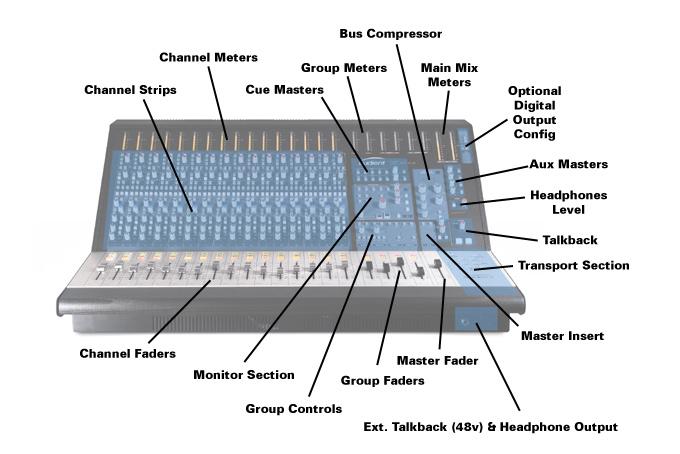
10 Introduction. Control Surface Overview Page -10-

11 Channel Strip Overview
12 Channel Strip. Zen features 16 high quality, flexible channel strips with a multitude of routing options. The channel strips are located on the left side of the console and the ergonomic, inclined profile of Zen ensures all controls are clearly visible and within arms reach. For consoles with the optional microphone preamplifier input stage, there are three main inputs: Mic Line DAW Each of these inputs is fed from their own rear panel XLR female connectors. For more information and specifications see the connections section. The channel strips also provide routing access to two mono and two stereo group busses as well as the main mix bus. Microphone Preamplifier Option With the microphone preamplifier option, a 75 Hz high pass filter, polarity reverse stage and 48v phantom power are also included. Two features that should be very useful during tracking, the HPF enables you to remove any rumble or subsonic noise and polarity invert provides alignment of sources such as snare top and snare bottom for example. On line input only Zen consoles - it is imagined that you will likely use external microphone preamplifiers if tracking - which should provide you with these features (or at least a polarity invert). If mixing - filtering and polarity invert are functions easily achieved within the DAW. Page -12-
13 Channel Strip. The three input stages and basic signal flow of the microphone preamplifier version of Zen is illustrated below: For consoles without the optional microphone preamplifier input stage, there are two main inputs: Line DAW The input stage signal flow for the line input only version of Zen is illustrated below: In typical operation it would be common to use the DAW input as the return path from your workstation outputs and use the mic/line path for recording (as psuedo in-line functionality is entirely possible with the direct output options). With two line inputs per channel (DAW and line), a 16 channel Zen can provide 32 dedicated line inputs for mixdown via the stereo cue alternative input selection. More detail further on... Page -13-
14 Channel Strip. Page -14-
15 Channel Strip. Peak Reading Bargraph Meter A 20-segment LED bargraph meter with peak detection, suitable for use in today s modern digital recording environment. 2dB per step, with a 38 db range. 0VU is calibrated to a nominal operating level of +4dBu. Which in turn is relative to a typical EBU calibration of +18dBu = 0 dbfs. 0 dbfs is your absolute maximum digital level (full scale) and should be avoided at all costs - digital clipping is not a pleasant sound. As such the bargraph meter scale on Zen is calibrated in dbfs, such that +4 dbu = 0VU = -14 dbfs. Therefore, a nominal operating level of 0VU will result in 14 db of headroom in your digital recording platform (providing your AD/DA converters are aligned to 0 dbfs = +18 dbu. 14 db of headroom is very useful as most music sources (except for the huge dynamic range of an orchestra) have crest factors (the difference between average (RMS) and peak level) of around db. Therefore Zen provides some headroom for your beautifully crisp transient sources. Page -15-
16 Channel Strip. High Pass Filter - Microphone Preamplifier option only A 75 Hz HPF with a 12 db per octave roll-off rate can be engaged on the mic/line source - useful for removing low frequency content that clutters up your mix and robs the console of headroom. Considering that many listeners use systems that can barely reproduce Hz accurately - a well placed HPF on certain sources can clean up mix elements that contain sub-sonic energy, such as microphone stand rumble, traffic noise, or some plosive material etc. 48v Phantom Power Engaging this switch provides 48 volt d.c phantom power to the microphone input. Phantom power is applied via a pair of current limiting resistors to XLR pin 2 (hot +ve) and XLR pin 3 (cold -ve). Zen phantom power is within the DIN specification of 48v, 10mA per channel. With individual phantom power switches on each channel - you have total control over which microphones receive power and rest assured that the powerful switch-mode power supply can deliver all the current needed for the most hungry of microhones. Phantom power wiring: Page -16-
17 Channel Strip. Line Input Select - Microphone Preamplifier option only Engaging this switch overrides the microphone preamplifer input with the line input - this is the channel source, which can later be swapped for the DAW input. Microphone Preamplifier Gain The optional microphone preamplifier fitted to Zen is the same class-a, low-noise hybrid design made popular with the ASP range of products. The amount of gain on offer here is 6 to 66 db of clean amplification and features a low-noise, differential discrete transistor input stage. With a minimum gain of 6 db and the option of taking a postfader direct output, Zen is capable of dealing with even the most aggressive of tracking sessions, ensuring headroom and clarity with total freedom from clipping your recording device. Post fade direct output also allows you to ride levels to tape or disk. Explore the direct output routings further (see channel strip item 8) and Zen can function in several flexible ways for tracking. Polarity Invert - Microphone Preamplifier option only A 180 o polarity invert function available for the microphone preamplifier - useful for tracking with multiple microphones. Page -17-
18 Channel Strip. Meter Select - (MTR) This switch alters the source to the peak reading bargraph meter. In the UP position, the channel input path feeds the meter, taken before the channel trim control (10) but after the mic/line and CH/DAW (9) routing selections. When engaged into the DOWN position, the meter takes its feed from the the direct output feed. Thus, its exact location is determined by the routing selections made in the direct output assign section (8) - see next item. Note that when engaged into the down position - the O/P LED lights, signifying the importance of paying attention to your direct output routing. During tracking - if a pre fader direct output is utilised - you may prefer to have the meter indicate channel input level (effectively the microphone preamplifier output level) so you can keep an eye on your recording levels. However if a post fader direct output is utilised - set the meter to O/P (DOWN) to ensure you see a true representation of your signal level post fader - including any rides you make during tracking. A neat way to use the dbfs scaled meter to avoid digital clipping. Page -18-
19 Channel Strip. Direct Output Routing This section is probably the most flexible element in the channel strip, providing 4 different signal path configurations for the entire channel strip, switched on a per channel basis. There are 4 modes to remember here - and they will seriously aid your workflow. POST PRE INS CH PRE FDR The first mode - POST requires both switches in the direct output routing section to be in the UP position. The direct output is taken POST FADER and POST MUTE. This configures the direct output as follows: This is a great mode to use for the following tasks: Riding levels to tape or disk when tracking (especially when microphone levels are hot Processing line level signals via the insert and printing back the effected sound to tape or disk with final level control Page -19-
20 Channel Strip. Direct Output Routing cont... The second mode - PRE INSERT requires the first switch in the direct output routing section to be in the DOWN position. The direct output is now taken PRE INSERT and PRE FADER. This mode configures the direct output as follows: This mode is useful when you want to take a clean feed during tracking, yet still monitor your signal with processing via the insert and set balances in real time, perhaps for headphone mix purposes with the processed signal on aux sends or the channel fader. This mode also provides extra gain during tracking via the channel trim control - a convenient place to ride levels and arguably a cleaner way of gain staging as opposed to varying the microphone preamplifier gain during a take. The third mode - PRE FADER requires the second switch in the direct output routing section to be in the DOWN position. This mode is useful when you want to take a pre fader record output with the addition of extra gain from the trim section and perhaps some processing (dynamics perhaps) on the insert. Page -20-
21 Channel Strip. Direct Output Routing cont... Pre fader routing may be the most useful if you are using the console faders to set a monitor balance and therefore do not want to have the faders change your recording levels. In this mode signal at the direct output is taken POST INSERT but PRE FADER. The fourth mode - CHANNEL requires both switches in the direct output routing section to be in the DOWN position. This is quite possibly the most useful mode for tracking if you are used to working on an in-line architecture. In normal use, CHANNEL mode allows the direct output to be taken direct from the microphone preamplifier, HPF and polarity inverter stage with no added gain stages such as channel trim. This provides the cleanest signal path for recording. Page -21-
22 Channel Strip. Direct Output Routing cont... If you do not have the microphone preamplifier fitted, this mode provides the cleanest path to feed your favourite outboard microphone preamplifiers to your recording platform - but with the added benefit on monitoring direct from the latency free environment of an analogue console. Using CHANNEL mode it is possible to combine it with the CH/DAW flip switch (9) to create a pseudo in-line architecture. When operating the channel in psuedo in-line mode you can effectively take the microphone preamplifier and polarity inverter output straight to the direct output (if microphone preamplifier option not installed then line input which could be fed from your external microphone preamplifiers). Whilst the line or microphone preamplifier input feed the direct output, the DAW channel input can be reconfigured to feed the rest of the channel path in two ways. One is via the alternative cue input (18) which allows monitoring of the signal to be recorded (prior to reaching its destination) by sending the channel input (line or mic) signal to the mix bus via its own level and pan control (15 & 17) and assigning the cue to the main mix bus (13). This would be the equivalent or similar of monitoring your short fader record path on an in-line architecture. By pressing the CH-DAW switch (9) DOWN the main channel path (equivalent of the long fader) is fed by the DAW line input. This would allow you to monitor the recorded signal from your workstation or tape machine. Making simple record and playback monitoring very quick and efficient. Page -22-
23 Channel Strip. Direct Output Routing cont... If you are using a tape machine with a delay between record and repro heads, or a workstation with noticable latency from input to output - the benefit here is huge. It is possible to feed your microphone preamplifier signal direct to tape or disk from the channel input. Meanwhile using the alternative cue input to feed a balance of the undelayed signal to your artist s headphone cue mix - whilst at the same time monitoring the main fader path fed from tape or disk so you can hear the colouration provided by your recording medium. Page -23-
24 Channel Strip. Channel / DAW Flip This function flips the sources to both the main channel path and the cue section alternative input. When the switch is in the UP position, the mic / line input feeds the main channel path, while the DAW line input feeds the cue section alternative input (which can optionally be selected in the cue section to turn the cue into an extra input with level, pan and bus routing). When the switch is engaged into the DOWN position - the sources to each section FLIP - therefore the mic / line input will feed the cue section alternative input and the DAW input will feed the main channel path. CH/DAW flip can be used to transform the console from a tracking arrangement where the mic/line source feeds the main channel path, aux/cue section and mix buses for monitoring into a mixdown situation, where the DAW input feeds the main channel path, providing full mixdown of DAW inputs with the 100mm linear faders or the optional automation system. Page -24-
25 Channel Strip. Channel Trim Control The potentiometer provides a trim range of +/-15 db and (depending upon your direct output routing) can be used as an extra boost of gain added to the microphone preamplifier when tracking - really useful for low output microphones such as ribbon transducer designs (some - not all). The trim control is also very useful for setting correct gain staging at the input of the console when utilising the line input (or the DAW input with the DAW/CH switch engaged into flip mode. Insert Active This switch when pressed DOWN engages the insert send and return loop for each channel (insert send and return balanced 1/4 TRS jack connectors found on the rear panel). This is a great place to insert your favourite outboard processors into the channel path. Please bear in mind that Zen can also be coupled with a patchbay to provide the ability to patch external outboard between your DAW outputs and the DAW input to also process signals entering this 2nd channel input. Please also bear in mind that with no TRS connectors plugged into the insert points (rear of the console) - the send and return jacks are normalled to prevent loss of signal during accidental engagement of the insert switch. Page -25-
26 Channel Strip. Insert Parallel Compression Technique Please bear in mind that the insert send is always active - the switch only engages the return path. Thus it is possible to mult signals from the insert send to set up parallel compression or feed other external destinations in parallel (a back-up recording system perhaps) by taking a feed from the insert send jack and returning the compressor output into another channel, or for simplicity the spare input on each channel (depending upon DAW/CH flip status this could either be the line input or DAW input. The diagram below illustrates how to connect such a path - in this example the main channel path input is taken from the DAW input (typical mixing scenario) by depressing the DAW/CH switch. This leaves the line input free for the return path from your outboard device - which can be returned to the mix bus via the cue section alt. input and bus assign. Page -26-
27 Channel Strip. Channel Bus Assign The channel bus assign switches allow you to send the post fader signal to the mono buses (M1 ans M2) and the stereo output of the pan pot (24) to the stereo buses (ST1 and ST2) and the main mix bus located in the master section. These switches exist in parallel, so routing to multiple groups simultaneously is highly useful and possible during mixdown. Multi-Bus Compression / Mix Technique Zen features two mono groups with pan two stereo groups and a main stereo mix bus. Thus it is possible to achieve a variation on the multi-bus compression technique made popular by NYC mix engineers like Michael Brauer. Please visit his website for more information. Page -27-
28 Channel Strip. Cue Section Bus Assign The stereo output from the cue send pan pot can be sent to multiple destinations. The cue bus assign section of the channel strip allows whatever signal is present on the cue section (either channel or DAW source) to be sent to the two stereo groups (ST1 and ST2) and the main mix bus (MIX). This is useful when tracking as it is likely that the cue section will be your starting point for creating artist cue mixes, but also useful for setting up extra mix sends. It is possible to solo the cue masters to audition and setup the cue mix balance from the control room - you hear what the artist hears. Adjust your balance and then return to your own control room balance which is set on the 100mm faders. It is possible to use the group outputs as extra monitor sends to headphone amplifiers and the like by using this routing functionality when tracking. However when mixng these features really come into their own - they can be used to set up parallel compression or processing with separate level control or if using the cue section as an alternative input (18) - the cue assign switches can be used to route this input to the three stereo buses. Great for expanding Zen to a 32-input mixing platform. Cue Assign There are two cue buses on Zen (CUE A and CUE B) which are primarily designed to feed your studio communication systems - headphone amplifiers etc. Page -28-
29 Channel Strip. Cue Pan The cue section pan control can be used to position sources into the stereo field of any of the stereo cue output destinations: CUE A, CUE B, ST1, ST2 and MIX. The pan control provides a smooth taper with an approximate pan law of -4dB, providing a decent compromise between constant power and constant voltage pan law design ideals. Cue Post Fader Assign Engaging this switch feeds the cue section with a post fader signal. With the switch in the UP position - a pre fader signal is used. Primarily it is expected this will be used during mixdown where the cue section may be sent to feed a reverb, in which case you will want the reverb level to drop with the main fader. However if using the cue section to send to a bus in parallel (a neat trick with a compressor or effect on the group insert) - you may decide you require a pre fade level to be sent, allowing two discrete level controls over signal to the busses. During tracking, it is likely you will use the send as a pre-fade feed, so that control room fader balances do not alter cue balances. In this case the switch should be in the UP position. This switch has no effect if the alt. input switch (18) is engaged (as it overrides the send functionality). Page -29-
30 Channel Strip. Cue Level The Cue Level control can be used as send level to the cue or group buses - or can be used as a 2 nd line input channel fader when the alt. input function (18) is used. Cue Alternative Input Select Engaging this switch turns a 16ch Zen into a 32ch channel fully capable mixdown platform. As already mentioned in this manual - there are many uses for this extra input path, from expanding your input quota for summing to returning effects processors and compressors. We are sure you will think of many innovative methods of incorporating this into your workflow. Aux Sends Pre Fader Assign Zen features two aux send control sections - which can feed two from four aux buses. Aux routing can be set on a per channel basis (see controls 21 and 22). Thus the total number of sends on Zen is 8 (Cue A [stereo] + Cue B [stereo] + Aux 1 + Aux 2 + Aux 3 + Aux 4). The aux send section of the console can be used to feed extra cue mixes and/or reverb units and such during tracking or mixing. For this reason, as with most consoles - Zen includes the option of a pre fade feed. Page -30-
31 Channel Strip. Aux Sends Pre Fader Assign cont... In their default state, the aux sends are set to post fader, but by depressing the switch they become pre fader. Please also note that the cue section in its default state is assigned to be pre fader (as this is most likely in a tracking s ituation, however this can be switched to post as detailed previously). Aux Send Switching The two aux send controls can each be toggled between a pair of aux bus destinations - thus doubling the total number of aux sends. In this case, AUX 1 can be switched to AUX 3 and AUX 2 can be switched to AUX 4 by engaging the appropriate switch. Aux Level Controls Aux 1 and Aux 2 level potentiometers to control the individual send level to each mono aux bus. Page -31-
32 Channel Strip. Channel Pan The pan control provides a smooth taper with an approximate pan law of -4dB, providing a decent compromise between constant power and constant voltage pan law design ideals. Both the cue and channel pan controls are centre detented for easy mono position. Channel Fader, Safe, Cut and Solo Controls Each channel uses a high-quality ALPS 100mm linear fader with +10 db of gain in-hand above unity. The console can also be fitted with optional moving fader automation (please see the automation section in this manual). Above each fader are three illuminated push switches. The first switch, SAFE (green LED) can be used to either isolate the channel from SOLO IN PLACE - useful for preserving elements in a mix while using the solo function. The SOLO switch places the channel into SOLO - either AFL or PFL (after fade or pre fade listen) or Solo in Place depending upon master section settings. The CUT switch operates a silent JFET-based mute circuit for click free operation. This is also controlled by the SOLO logic when in SOLO IN PLACE (SIP) mode. Page -32-
33 Mono & Stereo Groups Overview
34 Groups. Mono and Stereo Groups There are two mono and two stereo groups on Zen. These can be used for sub-mixing, parallel processing and even extra effects returns with a little bit of thinking and unorthodox behaviour! All groups feature inserts with parallel sum mode. This is fantastic for creating many levels of parallel compression in your mix. Part of the block diagram is shown below to illustrate how this is achieved. The mono groups feature pan controls to place them into either of the stereo groups (ST1 or ST2) or the main mix bus (MIX). All groups can be assigned to the stereo main mix bus (MIX). However the mono groups can also be assigned to the stereo groups (ST1 and ST2) - perfect for nested grouping of mix elements - kick and snare groups to drum group... lead vocal and lead vocal effects groups to vocal group... a high level of functionality indeed! Page -34-
35 Groups. All groups have rear panel balanced output XLR connections, making them suitable for submixing tracks during recording or printing processed mixes back to the recording platform. All groups feature high quality 100mm ALPS linear faders, with +10 db of gain in-hand above unity. All groups feature a SOLO and CUT switch located above the fader - in this case the CUT switch is relay based. Group output metering is calibrated to 0VU = +4dBu = -14 dbfs (please see the chart in channel strip section for reasoning). This is useful as group outputs may likely be used to record or printback submixes - thus keeping an eye on the metering should help avoid digital clipping in your recording platform, assuming -18dBu = 0dBFS calibration of your AD/DA. * TIPS & SUGGESTIONS If you only have a few choice bits of outboard compression and EQ - perhaps you could try using them across groups to maximise their benefit. It can be fun to try and split your mixes up into sections other than musical instrument elements - for example try using the two mono groups for sources with low frequency content and pan them centrally - using compression and EQ suited to these frequency ranges. Page -35-
36 Groups. Page -36-

37 Aux & Cue Section Overview
38 Aux & Cue Masters. Aux Masters Zen has four aux buses and a simple set of controls are provided for the master output of these buses. Each of the four aux masters features a level control - useful for reducing overload in some vintage digital reverb processors that may be connected here. The aux masters also feature a SOLO control, useful for listening to whatever blend you are sending to the output stage. Cue Masters There are two cue sections in the console - CUE A and CUE B. The cue buses (A & B) feed these sections, but so do a number of other sources - please be aware that these sources sum when more than one is selected. Page -38-
39 Aux & Cue Masters. Cue Masters cont... There are two external stereo inputs - DAW MIX and DAW FB (foldback). These two stereo inputs (found as rear panel line level XLR inputs) are intended to be used to monitor either the mix output of your DAW or a separate stereo foldback mix from your DAW. This is useful as headphone mixes are entirely possible at low latency with newer computers and low latency DSP devices. As such your headphone mixes can be saved within your session and even include effects for monitoring purposes. Along with the two external DAW MIX and FB inputs (both of which are also suitable to use as two-track returns) - the cue master section offers the ability to send the output of the AUX 1 and AUX 2 master summing stages to the cue outputs. This is useful if you are using the last option - C/RM (control room) as your main cue mix. A scenario that may often be encountered when you require that last absolutely essential vocal overdub during the final stages of mixing. If you are using all input channels including the alt. cue input for mixdown - you may decide to send the artist your control room balance - which can be achieved by engaging the C/RM switch. In this case you may use an aux send on a channel to send the artist more of themself without affecting your control room balance. To do this, just engage both the C/RM and whichever aux bus you are using (AUX1 or AUX2). We are sure you will find other uses for this function. Page -39-

40 Monitor Section Overview
41 Monitor Section. Page -41-
42 Monitor Section. The monitor section of Zen provides comprehensive control room monitoring options. The circuitry is mostly passive with only one buffer stage before the balanced loudspeaker outputs - thus providing you with a tonally neutral and accurate monitor path. There are a number of features that are very useful for checking the translation and content of your mixes. Please refer to the diagram and numbering the previous page when reading this section. Source Selection There are 5 sources that can feed the monitor section of Zen. DAW Mix - a stereo line input found as balanced XLR connectors on the rear panel. This stereo input can be used to audition in the box mixes quickly. DAW Foldback - a 2 nd stereo line input found as rear panel balanced XLR connectors. You may find this input very useful for auditioning headphone mixes that are created in the DAW. EXT. 1 Stereo - a 3 rd dedicated external stereo input found as balanced rear panel XLR connectors. Intended for use as a twotrack return for mixdown devices such as DAT machines, 1/2 and 1/4 tape machines and other devices. EXT. 2 Stereo - a 4 nd external stereo input input found as balanced rear panel XLR connectors. Can be used as the above. I-JACK - a front panel located, stereo mini jack connector. Designed for use with portable music players and the like - great to audition rough mixes as MP3 etc. Page -42-
43 Monitor Section. I-Jack Level Control & I jack Input A stereo level control for the I-Jack input. Polarity Invert Engaging this function polarity inverts the left channel of the mix, allowing you to check for stereo difference content when summed to mono, essentially creating a L-R sum. The switch is momentary to ensure it is not left on by accident! Mono Sum Engaging this function sums the left and right signals in the monitor section to produce a mono output. This is a useful feature for checking any issues that may arise with out of phase stereo content (especially at low frequency) and mono compatibility. It is also very useful to engage during the microphone placement phase when tracking, where a strong and consistent tonal balance can be achieved by adjusting stereo pair microphones in mono - until they provide the best tonal balance - hence hopefully minimising any phase cancellation when switched back into stereo. Cut L and Cut R Individual left and right output mutes can be engaged here - perfect for checking mono sum on a single speaker - which is often the most accurate method, minimising acoustic interaction from two (likely non-perfectly matched) sources. Page -43-
44 Monitor Section. Mix / SRC Select Engaging this switch toggles the feed to the monitor path between the output of the main mix bus and the external sources that can be selected at the top of monitor section. Alt Monitor Output Level Trim Zen features three sets of monitor outputs - typical used to feed farfield, nearfield and mini monitor sets or any three reference tools of your choice. The two alternative monitor outputs feature trim controls (overall volume is still determined by the master volume control (17). These can be used to match levels or set comfortable levels across all three loudspeaker sets. Loudspeaker Select Used to toggle between the three loudspeaker sets. Please note that these switches illuminate and have eletronically interlocking logic control to ensure only one set is active at any one time. Page -44-
45 Monitor Section. Main Monitor Volume A stereo level control for setting the main listening level. Solo Indicator An illuminated SOLO LED indicator displays the status of the console - actively engaging solo on any channel, group, cue or aux master will light this display to signify the status of the monitor section - which effectively switches to listen to the solo bus unless solo in place (SIP) mode is used in which case channels not in solo or in solo SIP safe mode will mute. Dim Level The monitor section includes a user-specified dim level that will lower the level of the output feeding the speakers when the dim function is engaged (21). Dim can be set anywhere from 0 to -20 db. Useful for dropping the level to take an important phone call! Dim Select Engaging this switch - dims the loudspeaker output by an amount set by the dim level control (20). Page -45-
46 Monitor Section. Main Monitor Cut A global main monitor cut. Disconnecting all loudspeaker outputs. Monitor Reference Level Engaging the monitor reference level bypasses the main volume control (17) and defaults to a preset trim pot reference level that can be accessed from the front panel. This reference level can be useful for monitoring at a calibrated listening level. To calibrate your reference level - systems can be adopted and adapted such as Bob Katz s K-System - for more info please see By setting your reference level to produce approximately 83 to 85 db SPL for a known and typical source level - it is possible to achieve a listening level that should ensure the ears are operating at their flattest frequency response due to aural perception and equal loudness contours. We recommend that you use the DAW MIX input and feed a -20 dbfs pink noise signal out from your DAW (or other suitable noise source), and set the input level such that it sits at 0VU. Use a calibrated SPL meter set to read with a slow response time, RMS detection and C-weighted filter (C-weighting is the most wideband weighting filter and most similar to the human ear at 85 db SPL. Place the microphone in the listening position - adjust the reference level trim pots until you read 85 db SPL from each loudspeaker. By returning to this level on program material you have a good chance of obtaining a constant and accurate reference level. Page -46-


47 Monitor Section. The master section of Zen also contains all communication functions. Talkback An integrated talkback microphone can be found in the master section within the compressor control panel area. This built-in electret microphone can be turned on to communicate with various output destinations on the console. There is a talkback level control which sets the gain of the talkback microphone preamplifier - which has a gain range of +20 to +55 db. An external talkback microphone can be selected with a separate XLR input found underneath the armrest to the right. To select this microphone and override the small electret in the compressor panel, engage the small recessed switch located above the talkback level control by using a long thin object to depress the switch. To engage 48v d.c phantom power for the external microphone, engage the small recessed switch found to the right of the XLR input underneath the armrest. There are two main talkback switches - both momentary to avoid leaving them on during delicate discussions! One talks to the cue outputs (CUE A and CUE B) and the other talks to SLATE - which feeds all the groups and main mix outputs. Both options activate dim in the monitor section to prevent feedback. Page -47-
48 Monitor Section. Solo Functionality Zen has four modes of solo which can be globally set from the master section of the console. AFL - After Fade Listen This mode is the default setting when the PFL switch in the master section is in the UP position. Solo feeds are taken after the channel fader and pan. The signal is sent to the stereo AFL solo bus and the monitor section switches to listen to this bus. PFL - Pre Fader Listen This mode is selected by depressing the PFL switch in the master section. Solo feeds are taken before the channel fader. The signal is sent to the mono PFL solo bus and the monitor section switches to listen to this bus. SIP - Solo In Place This mode does not use the solo bus to listen to channels in solo, instead the centre section returns a d.c control voltage command back to channel mutes, this way engaging solo still uses the main mix bus as the listen path, enabling solo of channels through mix bus processing etc. Also this mode can be combined with the solo SIP safe layer controls found in the transport section (right hand side of the console for those without the optional automation package. Solo SIP safe enables channels to not be muted during SIP activity - great for preserving vocal reverbs etc. Page -48-
49 Monitor Section. SIF - Solo In Front This mode is very useful as it allows you to listen in isolation or with a small amount of the main mix blended in - keeping a reference point in ear shot at all times. This is a continuously variable potentiometer. Please note that SIF does not work in SIP mode. Headphone Output There is a high quality stereo headphone output available on the Zen. The output connector is located underneath the armrest, next to the external talkback microphone input. The headphone output is fed from the monitor section of the console and thus its source is determined by the source select switch found in the monitor section of the console. The headphone output can be engaged with the switch on the right most side of the console, which is also where the headphones level control is found. Page -49-

50 Bus Compressor Overview

51 Bus Compressor. Zen features an integrated high class VCA bus compressor. It is located in the master section of the console on the right hand side. An adaptation of the compressor featured in the ASP8024 and Sumo, this is a design optimised for mix bus use. However with the addition of a wet/dry blend control for parallel compression and external patch capability, this compressor really works well on the drum bus (among other uses which we are sure you will find). Please note that by default it is located after the mix insert points. However as it can be externally patched and therefore removed from the mix bus path, it is freely assignable to any destination via its own balanced rear panel I/O. This way it is entirely possible to create a chain at the mix bus insert point with the VCA compressor followed by an outboard equaliser... a popular technique. Page -51-
52 Bus Compressor. Page -52-
53 Bus Compressor. Gain Reduction Meter A 10-segment LED bargraph meter indicating the amount of gain reduction. Due to the scale of the meter, sometimes you will only want the first few LEDs flickering to keep compression musical levels on the mix bus. The scale on the gain reduction meter ranges from 2dB to 20dB of compression. Attack Time Specified in milliseconds (ms) - this is the time taken for the compressor sidechain to react to the input signal above the threshold and trigger gain reduction (compression). Attack time can be set to: 0.1 ms 0.3 ms 1 ms 3 ms 10 ms 30 ms Typically on program material and mix bus use, slower attack times (try 10 or 30 ms for a punchy mix starting point) are preferred as they will not mangle transient material or distort low frequency content as much as faster times. If the attack or release time is faster than one cycle of the lowest frequency to be reproduced, distortion will occur as the compressor will alter the waveshape during one cycle. Remember that the period of one cycle, T(sec) = 1/f (Hz). Page -53-
54 Bus Compressor. Release Time Specified in seconds (S) - this is the time taken for the compressor sidechain to release from gain reduction once the input signal has passed below the threshold point. Release times can be set to: 0.1 Sec (100 ms) 0.3 Sec (300 ms) 0.6 Sec (600 ms) 1.2 Sec 2.4 Sec Auto Release Typically faster release times are required when you want the compressor to get out of the way quickly which can lead to pumping and very obvious compression. On vocal bus or piano longer release times and auto release are very useful. However if you want colourful compression on your drum bus, faster release times are worth trying. Start at 0.1 Sec and work backwards until you get a suitably balanced effect. Auto release utilises an adapative circuit that alters its release time in a program dependant manner. It is fantastically smooth and well suited to mix bus duty. Threshold The threshold control is specified in db and sets the point at which compression begins. There is a range of -20 to +20 db on this control. This compressor has a relatively smooth knee but the threshold point is similar for each ratio, making it predictable to set. Page -54-
55 Bus Compressor. Ratio Specified as a ratio of input vs output (in:out), the ratio control sets how much compression takes place once a signal has crossed the threshold point set in the sidechain circuitry. Example: A ratio of 2:1 indicates that when an input signal crosses the threshold by 2 db, an increase of only 1 db would be present at the output, thus 1 db of gain reduction would be produced. Generally, low ratios such as 1.5:1 and 2:1 are used over the main mix bus, however feel free to experiment. As the ratio increases, the compressor acts more like a limiter (10:1 and 20:1) and can be very useful or powerful on dynamics sources such as drums or vocals. Ratios can be set to: 1.2:1 (very gentle) 1.5:1 2:1 4:1 10:1 20:1 Gain Make-Up With a range of 20 db, the gain make-up control can be used to restore program material level after compression, thus reducing the dynamic range but preserving the overall output level. Page -55-
56 Bus Compressor. Wet / Dry Parallel Compression Parallel compression has been a popular mix technique that allegedly started in New York. Globally adopted, parallel compression is a fantastic way of preserving transient punch whilst simultaneously reducing dynamic range, through a form of upward expansion. We have added this functionality to Zen in many places. On the bus compressor there is a dedicated control, however on group and mix bus insert points it is possible to parallel inserts to achieve the same thing. Zen enables you to mix in a very modern way, with multiple levels of parallel compression and nested group compression. The wet and dry blend control on the bus compressor allows you to crossfade between the uncompressed and compressed signal. There are two useful starting methods when using parallel compression. One would be to set some gentle compression (low ratio) up 100% wet and then just edge back with a small amount of dry signal to add some punch back. The other school of thought involves setting up some rather aggressive compression (faster attack times and high ratios) and running the dry balance quite high so the smaller amount of compressed signal adds energy and dynamic colour. Page -56-
57 Bus Compressor. External Input The compressor can be patched to its own rear panel balanced I/O thus removing it from the main mix bus path and freeing it for use elsewhere in your mix. The rear panel compressor I/O can be found in the upper left hand corner of the console if facing it from the rear. Compressor In This illuminated push switch engages the compressor and also the gain reduction meter, so G.R can only be viewed when compression is active. Please see page xx for some example settings and starting points for this compressor. Happy mixing! Page -57-
58 Bus Compressor Settings. Page -58-

59 Main Mix Overview
60 Main Mix Bus. The main mix bus on Zen is optimised for clean summing with high headroom. Mix Bus Metering To gauge this headroom, large 30-segment LED peak meters calibrated to OVU = +4dBu = -14 dbfs (as the channel and group meters) are provided on the main mix path output. Mix Insert The mix bus features a switchable insert point. The insert send is always active regardless of switch state, and therefore can be used a pre master fader pick off point if desired. Main mix compression or processing can be set up in parallel as it can on the groups due to the parallel insert sum mode. Input Expansion The parallel insert sum at all of these stages can also operate as handy balanced line level expansion inputs. External summing devices can be used to add extra inputs by returning their output to the insert return point and engaging the insert sum switch. Page -60-
61 Main Mix Bus. The master section utilises a high quality 100mm ALPS stereo linear fader (as does the rest of the console - in either mono or stereo forms). Optional Digital Output Zen can be fitted with an optional digital output card. This card takes the main mix bus feed and allows you to take a high quality digital copy of your mix straight from the source to a digital destination. The optional output card provides high quality analogue to digital convertors supporting sample rates up to 192kHz (external WC only). AES/EBU connectivity is provided on 3 pin XLR, whilst S/PDIF is available on both Phono and TOSLINK connections. The card supports sample internal rates of 44.1, 48 and 96kHz, with sample rate selection available on front panel (top right hand corner). Higher sample rates are supported when the digital card is slaved to a master word clock connection via the BNC Word Clock input. Page -61-
62 Connections Overview
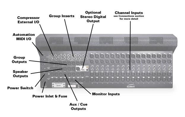
63 Connections. Zen features a plethora of connections in and out on the rear panel - as highlighted during the introduction of this manual. All XLR balanced input and outputs are wired as Pin 1 (shield - chassis/shield ground), Pin 2 (hot +ve) and Pin 3 (cold -ve). Channel Strip Inputs and Outputs The first input from (top to bottom) is the microphone XLR female input (optional). The input impedance of the microphone input is greater than 5k ohms and the maximum input level is approximately +16 dbu (where 0 dbu is referenced to V rms ). The next connection is the direct output - a balanced XLR male line output capable of +27 dbu,with a low output impedance of <75 ohms. The insert send jack comes next, a TRS connector wired Tip (hot), Ring (cold) and Shield (chassis/shield ground). Please note that this is an impedance balanced output with an output impedance of 150 ohms and a drive capability of +21 dbu. The insert return TRS jack is fully balanced with a >10k ohm input impedance and a maximum input level of +21 dbu. To finish off the channel I/O - there are a pair of balanced XLR female line inputs - Channel Line In and DAW Line In - both with an input impedance of >10k ohms and a maximum operating level of +27 dbu. Page -63-
64 Connections. Master Section Inputs and Outputs The remaining analogue I/O on the console follows the same specification. Group & Mix Bus Inserts Group and mix bus insert sends are impedance balanced with a 150 ohm output impedance and a maximum drive level of +21 dbu. The insert returns are fully balanced with a >10k ohm input impedance and a maximum input level of +21 dbu. External Compressor Inputs and Outputs The compressor inputs are fully balanced TRS connectors with a >10 kohm input impedance and a maximum input level of +27 dbu. The compressor outputs are also fully balanced with a 75 ohm output impedance and a maximum output level of +27 dbu. Group, Main Mix, Aux, Cue & Loudspeaker Outputs All of these outputs are fully balanced XLR male with a 75 ohm output impedance and a maximum drive capability of +27 dbu. External Monitor Inputs The four stereo pairs of monitor inputs are fully balanced XLR female with an input impedance of >10k ohms and a maximum input level of +27 dbu. Digital Output Option An optional stereo digital output can be fitted to the Zen, providing simultaneous AES3 (XLR), S/PDIF (RCA) and TOSLINK optical outputs. Page -64-
65 Connections. ASP510 Link The solo and dim control signals of the Zen console can link to the Audient ASP510 surround monitor controller. This enables the monitor controller to respond to console status to provide full solo and dim functionality when used in a 5.1 monitoring system. If you want to experiment with using the Zen in a 5.1 environment - try using a pair of aux sends as a centre and LFE feed, use the main fader and pan to send to a stereo group which is routed to left and right, with the cue send level and pan controlling rear left and rear right levels by going to another stereo bus. ASP510 9-Pin D-Sub Pin Out This connects to the 25-Pin D-Sub console interface (see page 6 of ASP510 manual for pin out detail). Page -65-
66 Connections. Unbalancing the Zen To unbalance an output from Zen, link pin 3 to pin 1 at the output of the console. To unbalance an input to Zen, link pin 3 to pin 1 at the source and leave the Zen input as a balanced connection. This will enable the Zen input stage to retain some CMRR (common mode rejection) even when fed from an unbalanced source. Total Number of Connections To provide a starting point for patchbay integration and cable purchasing - you may find the following table of information helpful. Connection Amount Type Microphone Input 16 XLR Female Direct Output 16 XLR Male Line Input 16 XLR Female DAW Input 16 XLR Female Channel Insert Send 16 TRS 1/4 Jack Channel Insert Return 16 TRS 1/4 Jack External Monitor Inputs 8 XLR Female Aux & Cue Outputs 8 XLR Male Group & Mix Outputs 8 XLR Male Group & Mix Insert Send 8 TRS 1/4 Jack Group & Mix Insert Return 8 TRS 1/4 Jack Loudspeaker Outputs 6 XLR Male Bus Compressor Input 2 TRS 1/4 Jack Bus Compressor Output 2 TRS 1/4 Jack Automation Midi I/O 4 MIDI 5-Pin DIN ASP510 Interface 1 9-Pin to 25-Pin D-Sub AES Digital Output 1 XLR Male ohms S/PDIF Digital Output 1 RCA Phono - 75 ohms TOSLINK Digital Output 1 Optical Wordclock Input 1 BNC - 75 ohms Page -66-
67 Automation Overview
 connections to your DAW (Digital Audio Workstation).")
68 Automation. Thank you for selecting the optional automation package for your Zen console. It should really enhance your mixing environment. The Zen automation package provides channel fader and channel mute automation via a series of MIDI (Musical Instrument Digital Interface) connections to your DAW (Digital Audio Workstation). The Zen automation communicates with your DAW via the Mackie HUI protocol. Any DAW that supports HUI control surfaces should work, however Zen has been optimised to work with Logic 8, Pro Tools 7.4+ (LE and HD), Cubase 4+ and Nuendo 3+. A 16 channel Zen console requires 2 x MIDI in ports and 2 x MIDI out ports for full 16 channel communication. These can be found at the rear of the master section (left most side, if facing Zen from the rear). Mackie HUI (Human User Interface) is a registered trademark of LOUD Technologies Inc. Page -68-
69 Automation. Overview of Functions The diagram below provides an overview of the automation system and the parameters that can be controlled. Zen not only provides fader and mute automation but also features an integrated DAW transport section, enabling quick and easy navigation of sessions with all key transport functionality. There are illuminated switches located in the transport section on the right hand side of the console for: Global Automation On/Off SIP Safe / Automation Safe Layer Select Fast-Forward Rewind Stop (often in many applications - a double tap here offers RTZ - return to zero) Play Record Page -69-
 safe switches - fantastically useful on mix elements you never want to lose when other tracks are in solo.")
70 Automation. Transport Panel Safe Layer The safe layer switches has two functions. When unlit, the safe switches on each channel operate as SIP (solo in place) safe switches - fantastically useful on mix elements you never want to lose when other tracks are in solo. Particularly handy when using channels as reverb or FX returns - solo your lead vocal and the reverb will still be heard without needing to solo it. When the safe layer switch is pressed and illuminated, the safe channel switches now operate as automation safe switches. Automation safe should be used when you want to isolate a particular channel from automation - for example - to audition rides without fighting existing automation data or without printing the rides if channels are still in write enabled. Note that both layers are stored and function simultaneously. By toggling the safe layer switch it is possible to obtain a rapid overview of both solo and automation safe channel settings. Safe layers are stored even after a power down, so remember to clear them manually if the next session requires a different set-up. Page -70-
71 Automation. Automation On The automation on switch enables (illuminated) or disables the console global automation status. We imagine that most people will work with automation disabled until the final stages of the mix process - however this function coupled with the automation safe switches allows you to add automation to a session/project at any stage but not be tied down to using it when perhaps all you want to do is set a rough balance, or audition a new ride or balance. The automation on switch can be useful for punching in automation, but is determined by two modes of operation as set by the Zenudu update application - see for further details. Mode 1 is known as Zen Master mode - which transmits the console fader values and mute status as automation is enabled. An example of its usefulness is outlined below: * TIPS & SUGGESTIONS Set the automation to Zen Master mode but start with the automation system turned off, a new balance could be set for a chorus section. The original verse section should be stored as DAW automation prior to working on the chorus balance - place the DAW channels into touch mode. Play the transition between verse and chorus with the automation system off, and a new balance set ready for the chorus - hit the automation on switch at the point of the chorus and the new balance will be punched into the chorus section. Useful. Page -71-
72 Automation & Transport. Mode 2 is known as DAW Master - which sets the Zen into slave mode, so that if and when automation is enabled - Zen immediately synchronises with the DAW and will update its status to that of the workstation. A great mode to enable smooth operation if you want to try a rough balance different to that of your stored automation balances. If you do happen to have moved your Zen fader balances with automation turned off but want to revert to the original DAW balance, DAW Master mode allows you to do so without the console reporting its new status to the DAW thus overwriting your old fader positions - in Zen Master mode the opposite is true - the DAW would update to the new balance, thus overwriting any previous balance. The DAW Master mode of course only helps if you leave DAW automation status in any form of write mode. In read mode, you would be protected from the Zen Master mode overwriting your session data. However please remember that you can undo the move in the DAW and these modes are provided for you to experiment and find a preference - they should be looked at as a refinement of the system. Transport Activity Please note that the transport panel on Zen is always active regardless of the automation state - therefore freeing you to navigate through your session as you choose. Page -72-
73 Automation & Transport. Function Switches 1 & 2 The function switches located below the safe layer and automation on switches are available for future development and currently have no function assigned to them. Please check for the latest firmware updates that will expand the functionality of these switches. Transport Switches Rewind Fast-forward Stop Play Record The transport switches are located at the bottom of the transport panel and provide all the usual suspects. Due to slightly different HUI implementations in each piece of DAW software, these controls behave slightly differently. For example in some applications (Logic) multiple presses of the fast-forward or rewind keys result in accelerating speeds of locate. Likewise, double tapping the stop key performs a return to zero (RTZ) operation in Logic, meanwhile in Cubase or Pro Tools it will depend upon Timeline Insertion or Transport preferences in each platform (please see the application specific set-up chapters for more information). Record modes must be set in each platform to provide punch record modes (Pro Tools Quick Punch etc). Page -73-
74 Automation. Connecting the Automation System To connect your 16 channel Zen automation system you will require the following: 4 x 5-pin DIN MIDI cables rd 1 x 3 party 2-in / 2-out MIDI interface (likely USB) 1 x cable of appropriate type to connect your MIDI interface to your DAW rd Drivers installed on your DAW for the 3 party MIDI interface Available interfaces include the M-Audio Midisport, EMU X- MIDI 2x2, Motu Fastlane/Express series among many others. Connect Zen to the MIDI interface as follows: Page -74-

75 Automation. Setting Up Automation in Apple Logic 8 Zen automation performs excellently with Logic and can be set up to seamlessly integrate into your existing sessions. Please connect the console as previously described, boot Logic 8, create a new session and follow these set-up instructions... Step 1. Logic Pro > Preferences > Control Surfaces > Setup... Step 2. Install a new HUI control surface Page -75-

76 Automation. Logic 8 cont... Step 3. Select Mackie Designs > Model: HUI > Module: HUI > click Add Step 4. Assign the MIDI input and output ports to your MIDI interface Page -76-


77 Automation. Logic 8 cont... Step 5. Set the first HUI control surface to Port A or Port 1, whichever is displayed Once assigned Logic should appear as follows: Page -77-
. Step 7.")
78 Automation. Logic 8 cont... Step 6. Select New to install a 2 nd device This time add a HUI Channel Strips only surface to complete the final bank of control data for Zen. The HUI protocol operates in banks of 8, so effectively the 2 nd bank work as channel strips only in a master-slave relationship with the first full HUI controller (bank 1/faders 1-8). Step 7. Select Mackie Designs - Model: HUI Channel Strips only - Module: HUI - click Add Page -78-

")

79 Automation. Logic 8 cont... Step 8. Logic will tell that a HUI is already installed but you can go ahead and add the Channel Strips only... Step 9. Click on the HUI Channel Strips only icon (if not selected) and assign the 2 nd set of MIDI ports, this time either as Port B or Port 2 (or whatever you have available if using larger 4x4 and 8x8 MIDI interface types). Page -79-

 Please set the maximum MIDI bandwidth to 100% c.")
80 Automation. Logic 8 cont... Step 10. At this point you can close the control surface setup window as you should have successfully installed both surfaces. From here a few preference tweaks are needed to ensure smooth operation. Logic Pro > Preferences > Control Surfaces > Preferences... Step 11. a.) Please set the resolution of relative controls to 1024 (or any value greater than 512) b.) Please set the maximum MIDI bandwidth to 100% c.) De-select control surface follows track selection You can also de-select touching fader selects track if that improves your workflow within Logic Page -80-

81 Automation. Logic 8 cont... Step 12. Return to the arrange page and create 16 new mono dummy audio tracks for Zen automation to follow and write to. Page -81-


82 Automation. Logic 8 cont... Step 13. Label the 16 audio tracks something easy to read and locate in your session, Zen 1 through 16 perhaps. Step 14. This one is entirely up to you, but we recommend you de-assign any input and output track routing so that you do not inadvertantly record audio on to automation only tracks, as these tracks should contain no audio. Tracks can then be freely assigned into the various automation modes to record fader movements or cut status in complete synchronisation with your DAW. Use the Zen transport panel to navigate your session and ride faders and cuts to your heart s content. Page -82-
, returning to previously recorded automation data")

83 Automation. Automation Modes in Logic We recommend the use of Touch, Latch and Read mode for the majority of your work. Touch mode provides the most essential workflow, writing automation data when a fader is touched and moved (the Zen faders are touch sensitive), returning to previously recorded automation data when a fader is released. Latch mode is useful but be careful as it will Latch to the last touched fader position until play/record is stopped so you may overwrite important rides. However, fear not, you always have multiple stages of undo in the DAW. Read mode is to be used for playback of automation data. Be very very careful in Logic when in Write mode as Logic may automate any paramater touched, plug-ins, EQ bands - the lot if you re not careful! Page -83-


84 Automation. Writing and Viewing Automation in Logic Once setup, rides and mutes can be recorded into Logic and viewed, edited or manually drawn like any other DAW based automation. To view your recorded automation press A (standard Logic keyboard shortcut) or click on the automation icon at the top of the screen. Organise your sessions so that Zen automation tracks are the first 16 tracks in Logic. This keeps them easy to find and always set to the control surface. You may also find it useful to hide these tracks using the very handy hide function in Logic. However in order for this to work, Logic s channel strip view mode must be set to tracks in control surface setup. Page -84-


85 Automation. Hiding Tracks in Logic Accessed by pressing H on the DAW keyboard or clicking on the little H hide icon at the top of the arrange page. Set the Zen channels to hide by clicking the little H on each channel and then toggle H to show / hide. Useful as the automation data still works as normal but you can keep your DAW session tidy. Page -85-
 Zen automation performs excellently with Pro Tools and")

86 Automation. Setting Up Automation in Pro Tools (LE or HD) Zen automation performs excellently with Pro Tools and can be set up to seamlessly integrate into your existing sessions. Please connect the console as previously described, boot Pro Tools, create a new session and follow these set-up instructions... Step 1. Setup > Peripherals... Step 2. Click on the MIDI Controllers tab at the top of the window Page -86-

87 Automation. Pro Tools cont... Step 3. Add two HUI control surfaces into the first two MIDI controller slots in the peripherals window. Step 4. Assign receive from and send to to your MIDI interface ports. Page -87-


88 Automation. Pro Tools cont... Step 5. Ensure that the first HUI device is set to Port A or Port 1, and the second set to Port B or Port 2. Of course you can absolutely assign to any MIDI port you want, but this keeps things organised. When finished click OK. Step 6. Return to the edit window and create 16 new mono dummy audio tracks for Zen automation data (Pro Tools shortcut Command+Shift+N on Mac or CTRL+Shift+N on PC). Page -88-


89 Automation. Pro Tools cont... Step 7. Place these 16 tracks at the start of your session and label them something easy to read and spot in your session. Zen 1 through 16 perhaps. Step 8. To ensure that Pro Tools fixes the control surface to these 16 automation tracks we must use the scroll into view feature. You may find that if you add automation tracks into a session that already contains a number of audio tracks, that the control surface may be set to follow a series of 16 incorrect tracks. The scroll into view feature allows you to fix the control surface to the first 16. Page -89-

 on the first Zen track")

90 Automation. Pro Tools cont... Step 8 cont... The image below illustrates Pro Tools incorrectly set to unwanted tracks - note the bold blue squares around the channel names. To rectify this, CTRL+click (Mac - right click on PC) on the first Zen track (Zen 1 in this example) - this will bring up a dialogue box with the option - Scroll Into View - select this option, note that all 16 Zen tracks should be highlighted (bold squares) in both the Mix window and the Edit window. Page -90-

91 Automation. Automation Modes in Pro Tools Zen will respond to all automation modes in Pro Tools, thus much functionality is gained through this host. It is possible to use Read, Write, Touch, Latch or Trim and even VCA fader groups to link channels on the Zen. VCA faders and Trim provide options previously only found on large format consoles. Trim mode is useful for keeping micro rides intact whilst trimming sections up or down relative to the ride. Great for adding that extra couple of db that always seems needed! As with Logic, Touch and Read are great places to start. Automation can be viewed and edited easily, just as all in the box automation. Page -91-


92 Tweaking Transport and Automation Behaviour in Pro Tools A few small tweaks can be made in Pro Tools to improve automation performance, however some of these will affect ALL automation in your session so complete at your own discretion. Pro Tools Timeline Insertion can help you return to a previous starting position after an automation pass to re-take, or it can be set to ensure that the timeline playhead stops where you tell it to with the transport stop command. Great for marking edit points or working in sections while laying automation. To toggle this option on or off go to: Pro Tools LE (HD) 7.4.x or 8.x.x > Preferences......Operation Tab Page -92-

93 Automation. Tweaks in Pro Tools cont... Whilst still in the Preferences window, select the Mixing tab... Here you can thin automation data to reduce CPU load on your DAW host. This may be useful if your session is automation heavy and needs a helping hand. This setting applies to all automation data in the session but is useful at removing lots of unnecessary data. Reducing the amount of data sent to the Zen will also be of benefit to overall fader action and smooth motion. To further enhance the feel of the system, AutoMatch time can be adjusted. Here you set the time taken for Pro Tools to crossfade from the last touched fader position back to the existing DAW fader position. This mode helps Zen feel smooth when exiting a ride in touch mode. Zen has been optimised for smoothness of action, but you may find this setting improves the feel of automation and general eveness of fades during release of touch data. Page -93-


94 Automation. Pro Tools LE Running Out of Tracks? As Pro Tools LE provides limited track count, you may feel that using 16 just for the automation system leaves you a little short... Well, good news. Due to Digidesign s voice assign feature, you can turn off voice allocation for the 16 automation tracks, therefore allowing you to use your full track count for audio. The same holds true for Pro Tools HD users where you may be running out of voices on large sessions. One way to de-assign channel voices, is to click and select the appropriate option at the bottom of each fader denoted by the small V symbol. Page -94-

95 Automation. Setting Up Automation in Cubase4 / Nuendo 3 Zen automation performs well with Cubase / Nuendo but will likely improve over time as new firmware updates are released. Please see for details and updates. Please connect the console as previously described, boot Cubase or Nuendo, create a new session and follow these set-up instructions... Step 1. Goto Devices > Device Setup... Step 2. From here, select the MIDI Port Setup tab and check that your MIDI interface is registered and active. Page -95-


.")
96 Automation. Cubase / Nuendo cont... Step 3. Select the remote devices tab, and click the + sign to add a new control surface, here add the Yamaha DM2000 template Step 4. Assign the MIDI input and output ports to your MIDI interface (Port A or Port 1). Page -96-


97 Automation. Cubase / Nuendo cont... Step 5. Apply the settings for the first control surface device Step 6. Add a 2 nd DM2000 control surface and assign MIDI ports 2 or B as its input and output destination. Page -97-


98 Automation. Cubase / Nuendo cont... Step 7. Click OK and return to the project arrange page. Here, create 16 new mono dummy audio tracks for automation to write to and read from. Project > Add Track > Audio Step 8. Place the 16 audio tracks at the start of your project and label them something easy to read and locate. Perhaps Zen 1 through 16. You should be ready to go! Page -98-


99 Automation. Automation Modes in Cubase / Nuendo Both Cubase 4 and Nuendo 3 differ slightly in automation modes, and the new Cubase 5 and Nuendo 4 automation panel offers plenty of depth such as virgin territories, all of which should function well with the Zen. The setup instructions provided here are specifically relevant to older versions of Cubase (4 and previous). Here there are three modes of automation available. Read Read+Write Write Please consult your Cubase or Nuendo manual for more detail. Page -99-


100 Automation. Keeping Your Project Tidy Both Cubase and Nuendo provide the option to store your tracks within folder tracks (as can Logic). This is useful for minimising session clutter and a neat way to store Zen tracks. Place a folder at the start of your project and name it something like Zen 16 Ch. Highlight the 16 Zen automation dummy audio tracks by using the SHIFT key and SHIFT+click and drag the tracks into the folder. Tracks can still be accessed via the inspector for altering automation modes. Page -100-


101 Automation. Viewing and Editing Automation in Cubase 4 To view and edit automation data in Cubase 4, go to: Project > Track Folding > Show All Used Automation Alternatively, view automation on a track by track basis using local track folding. Page -101-


102 Automation. Cubase Transport Control Tweaks Something you may find useful (and similar to Pro Tools) are the two options for Cubase transport location. Go to Cubase > Preferences... Transport tab Here you can set the playhead to return to start position on stop. This is useful for running passes of automation, for example riding a lead vocal during the all important final chorus. Perhaps you are not happy with the first ride pass... With this option selected, selecting stop on the Zen or Cubase transport will return the playhead to your starting point ready for another run. De-select if you want to remain at your stop location. Page -102-
103 Automation. Updating System Firmware Over time a number of updates are likely to happen to the Zen automation system. Also, with the possibility of new emerging control surface protocols Zen utilises on-board flash memory to facilite firmware update, refinement and future proof operation. Added functionality is likely to be added to the two function keys in the transport section, expanding the control possibilities. Please check for future updates and firmware revisions. If you do need to update your Zen firmware at any point, we have handily produced a software update interface that resides on your host machine and uses MIDI to transmit updates to the console. Zenudu The aptly named Zenudu (Zen Update Utility) is a small application that makes updates simple and easy. Please see for the current Zenudu version. Once installed, look out for the Zenudu icon. Please ensure your console is powered up and connected via MIDI to your host. After downloading the latest firmware update (a.bin file), boot Zenudu and follow these instructions... Page -103-

104 Automation. Updating System Firmware Zenudu will open and you must set the appropriate MIDI input and output ports to talk to the console. These should be remembered upon subsequent boots - providing the interface is still attached to the computer. Once connected, click Get to find the currently loaded version number. This should be almost instantaneous, if not - please double check your connections and MIDI I/O assignment. Page -104-


105 Automation. Updating System Firmware Locate your freshly downloaded update.bin file by going to: File > Open... Once selected, proceed to update the console, either in banks of 8, or all at once. The progress bar to the bottom left will empty once completed. Run Get one final time to ensure the update was sucessful - you re done! Page -105-
106 Warranty. Your Zen comes with a manufacturer s warranty for one year from the date of despatch to the end user. The warranty covers faults due to defective materials used in manufacture and faulty workmanship only. During this warranty period Audient will repair or at its discretion replace the faulty unit provided it is returned carriage paid to an authorised Audient service centre. We will not provide warranty repair if in our opinion the fault has resulted from unauthorised modification, misuse, negligence, act of God or accident. We accept a liability to repair or replace your Zen as described above. We do not accept any additional liability. This warranty does not affect any legal rights you may have against the person who supplied this product it is additional to those rights. Limitations This warranty does not cover damage resulting from accident or misuse. The warranty is void unless repairs are carried out by an authorised service centre. The warranty is void if the unit has been modified other than at the manufacturer s instruction. The warranty does not cover components which have a limited life, and which are expected to be periodically replaced for optimal performance. We do not warrant that the unit shall operate in any other way than as described in this manual. Page -106-

107 Audient LTD 1 Stable Court Herriard Park Herriard Hampshire RG25 2PL UK Phone: +44 (0) Fax: +44 (0)
T L Audio. User Manual C1 VALVE COMPRESSOR. Tony Larking Professional Sales Limited, Letchworth, England.
 T L Audio User Manual C1 VALVE COMPRESSOR Tony Larking Professional Sales Limited, Letchworth, England. Tel: 01462 490600. International +44 1462 490600. Fax: 01462 490700. International +44 1462 490700.
Master Section
 Master Section -18 9 9 18 VU VU The Master section of the Custom Series 75 is host to two linkable (and externally patchable) mono 2254 compressors, the 281 Channel Module routing options, eight Groups,
Overview. A 16 channel frame is shown.
 Overview A 16 channel frame is shown. 22 Mono Input Channel 1 - MIC INPUT The mic input accepts XLR-type connectors and is designed to suit a wide range of BALANCED or UNBALANCED signals. Professional
1608-II and 2448 Recording Console Operator s Manual
 Recording Console Operator s Manual Written for Automated Processes ncorporated by Dan Pfeifer Rev. 18-12-30 2018 8301 Patuxent Range Road Jessup, MD 20794 USA 301-776-7879 http://www.apiaudio.com Table
Introducing the New Daking Console
 Introducing the New Daking Console Daking The Console that can change from a Legacy Bussing scheme to DAW Direct Routing with the touch of a button. Features: Class A Circuitry Transformer Coupled Pre-Amps
TL AUDIO M4 TUBE CONSOLE
 TL AUDIO M4 TUBE CONSOLE USER MANUAL TL AUDIO M4 TUBE CONSOLE M4 INTRODUCTION... 3 M4 MIXER TECHNICAL SPECIFICATION... 4 Mic Input:... 4 Line Input:... 4 Phase Rev:... 4 High Pass Filter:... 4 Frequency
THE BOX 8 Recording & Mixing Console Operator s Manual
 Recording & Mixing Console Operator s Manual Written for Automated Processes Incorporated by Dan Pfeifer Rev. 19-1-15 2019 8301 Patuxent Range Road Jessup, MD 20794 USA 301-776-7879 http://www.apiaudio.com
S1 Digital/Analogue Radio Broadcast Mixer
 S1 Digital/Analogue Radio Broadcast Mixer September 2009 www.sonifex.co.uk t: +44 (0)1933 650 700 f: +44 (0)1933 650 726 sales@sonifex.co.uk S1 Radio Digital/Analogue Broadcast Mixer Radio Broadcast Mixer
S1 Digital/Analogue Radio Broadcast Mixer September 2009
 S1 Digital/Analogue Radio Broadcast Mixer September 2009 www.sonifex.co.uk t: +44 (0)1933 650 700 f: +44 (0)1933 650 726 sales@sonifex.co.uk S1 Radio Digital/Analogue Broadcast Mixer Radio Broadcast Mixer
FF DUAL FORMAT DJ MIXER USERS MANUAL
 FF - 4000 DUAL FORMAT DJ MIXER USERS MANUAL FF - 4000 INTRODUCTION The features and layout of the FF-4000 were determined in collaboration with leading loudspeaker manufacturers Funktion One, who canvassed
Introduction SAFETY PRECAUTIONS. Contents
 0 0 0 0 9 8 7 6 0 0 9 8 7 6 0 0 9 8 7 6 0 Contents Introduction Safety Precautions Connections System Overview Controls in Detail Inputs Master 7 Advanced Features 8 Initial Setting Up 9 Applications 0
S0 Radio Broadcasting Mixer. June catalogue. Manufacturers of audio & video products for radio & TV broadcasters
 S0 Radio Broadcasting Mixer June 2012 catalogue Manufacturers of audio & video products for radio & TV broadcasters S0 Radio Broadcasting Mixer A simple radio mixer for novice and professional users The
Mixers. The functions of a mixer are simple: 1) Process input signals with amplification and EQ, and 2) Combine those signals in a variety of ways.
 Process input signals with amplification and EQ, and 2) Combine those signals in a variety of ways.") Mixers The mixer is the central device in any sound studio. Although you can do a lot without it, sooner or later you are going to want to bring all of your materials together to make a piece of music,
Mixers The mixer is the central device in any sound studio. Although you can do a lot without it, sooner or later you are going to want to bring all of your materials together to make a piece of music,
CHAPTER 3 AUDIO MIXER DIGITAL AUDIO PRODUCTION [IP3038PA]
![CHAPTER 3 AUDIO MIXER DIGITAL AUDIO PRODUCTION [IP3038PA]](/thumbs/73/68858919.jpg "CHAPTER 3 AUDIO MIXER DIGITAL AUDIO PRODUCTION [IP3038PA]") CHAPTER 3 AUDIO MIXER DIGITAL AUDIO PRODUCTION [IP3038PA] Learning Objectives By the end of this chapter, students should be able to: 1 State the function of the audio mixer in the sound studio. 2 Explain
CHAPTER 3 AUDIO MIXER DIGITAL AUDIO PRODUCTION [IP3038PA] Learning Objectives By the end of this chapter, students should be able to: 1 State the function of the audio mixer in the sound studio. 2 Explain
Recording to Tape (Analogue or Digital)...10
...10") c o n t e n t s DUAL MIC-PRE Green Dual Mic Pre (introduction).............................4 Section (i): Setting Up Power Connections...........................................4 Power Supply................................................5
c o n t e n t s DUAL MIC-PRE Green Dual Mic Pre (introduction).............................4 Section (i): Setting Up Power Connections...........................................4 Power Supply................................................5
MIDAS Venice Pin-Assignments Page 1 / 3 Mono-Channel-PCB Stereo- / Master - PCB CN 1 circuit diagram number CN 6 circuit diagram number CN
 MIDAS Venice Pin-Assignments Page 1 / 3 Mono-Channel-PCB 81346 Stereo- / Master - PCB 82230 CN 1 circuit diagram number CN 6 circuit diagram number CN 7 circuit diagram number CN 1 circuit diagram number
IN IN IN IN A A A B B B
 4 PRE 9-10 0 10 0 10 0 10 0 10 0 10 0 10 0 10 0 10 HF/LF HF/LF HF/LF HF/LF IN IN IN IN 10kHz 10kHz 10kHz 10kHz db db db db 18kHz + 18kHz + 18kHz + 18kHz + MIDS MIDS MIDS MIDS 3.2 100Hz db + 100Hz db +
SAFETY PRECAUTIONS. The SPIRIT FX16 mixer must only be connected through the Power Supply supplied:
 INTRODUCTION Thank you for purchasing an FX16 mixer, brought to you with pride by the SPIRIT team of Andy, Colin, Chris, Simon, Mukesh, Graham, Martin, Paul, Tony and Peter, with the support of many others
X-Four console. description. features. sound fundamentals. built to defy murphy s law. wide range of configurations
 X-Four console description If your application requires all the features and performance of a thoroughly-professional mixing console, but presents severe spacerestrictions, then the Crest Audio X-Four
Recording & Mixing Console Operator s Manual
 Recording & Mixing Console 11-12-13 Written for Automated Processes Incorporated by Dan Pfeifer 2013 1 Table of Contents 1.0 Overview 2.0 Input Channels 1-4 2.1 Preamp 2.2 Filter, Routing, and Meter 2.2.1
M A S T E R S E C T I O N. User Manual
 M A S T E R S E C T I O N User Manual Version 1.02: July 2007 Contents. Safety Information.... 3 Welcome.... 4 Connections.... 5 A Basic Set-up 5 Setting Up.... 7 Adjusting Input Levels 7 Taking Account
3124mb+ All Discrete 4 Channel Mic/Instrument Preamplifier with Stereo Mixer Operator s Manual
 3124mb+ All Discrete 4 Channel Mic/Instrument Preamplifier with Stereo Mixer Operator s Manual Written by Carl J Houde 2015 Table of Contents 1.0 Introduction... 3 2.0 Overview... 4 2.1 3124mb+ Features
Chameleon Labs Model 7720
 Chameleon Labs Model 7720 Stereo Compressor Owner s Manual 704 228 th Avenue NE, # 826 Sammamish, WA 98074 206-264-7602 www.chameleonlabs.com Revision C - December, 2007 UNPACKING AND INSPECTION Carefully
M-16DX 16-Channel Digital Mixer
 M-6DX 6-Channel Digital Mixer Workshop Getting Started with the M-6DX 007 Roland Corporation U.S. All rights reserved. No part of this publication may be reproduced in any form without the written permission
Solid State Logic S O U N D V I S I O N
 Solid State Logic S O U N D V I S I O N SUPERANALOGUE X - R A C K Super-Analogue Outboard XR622 X-Rack Master Module User s Guide This documentation package contains the User s Guide for your new X-Rack
CLA MixHub. User Guide
 CLA MixHub User Guide Contents Introduction... 3 Components... 4 Views... 4 Channel View... 5 Bucket View... 6 Quick Start... 7 Interface... 9 Channel View Layout..... 9 Bucket View Layout... 10 Using
Chapter 4 Signal Paths
 Chapter 4 Signal Paths The OXF-R3 system can be used to build a wide variety of signal paths with maximum flexibility from a basic default configuration. Creating configurations is simple. Signal paths
User Manual. Neve Channel Strip Issue 2. !!!Please read includes important safety instructions!!!
 User Manual Neve 8801 Channel Strip 527 358 Issue 2!!!Please read includes important safety instructions!!! 2007 AMS Neve Ltd own the copyright of all information and drawings contained in this manual
MULTI PURPOSE MIXERS.
 GRAHAM BLYTH FRSA To mark Soundcraft s 30th anniversary, co-founder and Technical Director, Graham Blyth, took a well established and classic Soundcraft microphone preamplifier to a new level of performance,
X-Panda User s Guide
 X-Panda User s Guide This documentation is intended to be read along side the X-Panda Installation Guide which is available for download from our website www.solidstatelogic.com 82BXEM01A Contents Introduction
ANALOG RADIO MIXER. Flexible. Affordable. Built To Last.
 ANALOG RADIO MIXER Flexible. Affordable. Built To Last. Audioarts AIR-4 A N A L O G R A D I O M I X E R At Audioarts, value engineering is straightforward: Define the features our customers require. Design
Neve :2 Summing Mixer User Manual
 Neve 8816 16:2 Summing Mixer User Manual 527-361 Issue 5 AMS NEVE Billington Road Burnley Lancs BB11 5UB England Phone +44 (0)1282 457011 Fax: +44 (0)1282 417282 info@ams-neve.com www.ams-neve.com www.neve.eu
12 Channel Media Splitter MS12 Mk2 User manual
 12 Channel Media Splitter MS12 Mk2 User manual 01. 12 Channel Media Splitter MS12 Mk2 An audio distribution amplifier primarily designed to feed multiple ENG cameras from a single lectern microphone at
CM4-BT. Compact Mixer with Bluetooth UK User Manual
 CM4-BT Compact Mixer with Bluetooth 170.804UK User Manual Caution: Please read this manual carefully before operating Damage caused by misuse is not covered by the warranty Introduction: Thank you for
1073DPA and 1073DPD Mic Pre- Amplifier
 AMS NEVE 1073DPA and 1073DPD Mic Pre- Amplifier 527-349 Issue 2 2005 AMS Neve plc own the copyright of all information and drawings contained in this manual which are not to be copied or reproduced by
USER MANUAL MX102 & MX1202
 USER MANUAL MX102 & MX1202 WWW.PULSE-AUDIO.CO.UK 1 SAVE THESE SAFETY INSTRUCTIONS Thank you for purchasing our product. To assure the optimum performance, please read this manual carefully and keep it
CFX 12 (12X4X1) 8 mic/line channels, 2 stereo line channels. CFX 16 (16X4X1) 12 mic/line channels, 2 stereo line channels
 8 mic/line channels, 2 stereo line channels. CFX 16 (16X4X1) 12 mic/line channels, 2 stereo line channels") COMPACT CFX MIXERS COMPACT SOUND REINFORCEMENT MIXERS WITH EFX FOR THE GIGGING MUSICIAN THREE MODELS CFX 12 (12X4X1) 8 mic/line channels, 2 stereo line channels CFX 16 (16X4X1) 12 mic/line channels, 2
COMPACT CFX MIXERS COMPACT SOUND REINFORCEMENT MIXERS WITH EFX FOR THE GIGGING MUSICIAN THREE MODELS CFX 12 (12X4X1) 8 mic/line channels, 2 stereo line channels CFX 16 (16X4X1) 12 mic/line channels, 2
L+R: When engaged the side-chain signals are summed to mono before hitting the threshold detectors meaning that the compressor will be 6dB more sensit
 TK AUDIO BC2-ME Stereo Buss Compressor - Mastering Edition Congratulations on buying the mastering version of one of the most transparent stereo buss compressors ever made; manufactured and hand-assembled
THERMIONIC CULTURE. TheEarlybird 2.2. valve microphone pre-amplifier OPERATING MANUAL
 THERMIONIC CULTURE TheEarlybird 2.2 valve microphone pre-amplifier OPERATING MANUAL WARNING For your personal safety, please read this operating manual and warning thoroughly before using the equipment.
GS-CU001M COMMENTATOR UNIT PRODUCT DETAILS
 GLENSOUND ELECTRONICS LTD GS-CU001M COMMENTATOR UNIT PRODUCT DETAILS 6 BROOKS PLACE, MAIDSTONE, KENT, ME1 1HE. ENGLAND. TEL: + (0) 1622 7020 Visit our Website at www.glensound.co.uk + (0) 1622 7662 FAX:
PROFESSIONAL 2 CHANNEL SOLID-STATE MIC / LINE PREAMPLIFIER USER S MANUAL
 PROFESSIONAL 2 CHANNEL SOLID-STATE MIC / LINE PREAMPLIFIER USER S MANUAL SAFETY INSTRUCTIONS This symbol, wherever it appears, alerts you to important operating and maintenance instructions in the accompanying
y AW4416 Audio Workstation Signal Flow Tutorial
 y AW44 Audio Workstation Signal Flow Tutorial This tutorial will help you learn the various parts of a CHANNEL by following the signal through #1. Use the Signal Flow Diagram included with this document.
LX20 OPERATORS MANUAL
 LX20 OPERATORS MANUAL CONTENTS SAFETY CONSIDERATIONS page 1 INSTALLATION page 2 INTRODUCTION page 2 FIRST TIME USER page 3 SYSTEM OPERATING LEVELS page 3 FRONT & REAR PANEL LAYOUT page 4 OPERATION page
CMX-DSP Compact Mixers
 CMX-DSP Compact Mixers CMX4-DSP, CMX8-DSP, CMX12-DSP Introduction Thank you for choosing a Pulse CMX-DSP series mixer. This product has been designed to offer reliable, high quality mixing for stage and/or
Radio for Everyone...
 Radio for Everyone... P R O D U C T I O N O N A I R C O N S O L E Eight dual inputs Built in auto Silence detector 4 USB in/out stereo channels Play out USB control section included AES 3 digital program
AxumVideo 0 intro. Now that you have connected the different AXUM system parts, you are ready to configure the system according to your own needs.
 AxumVideo 0 intro Now that you have connected the different AXUM system parts, you are ready to configure the system according to your own needs. On the left we see the RACK unit and on the right we see
CLOCKAUDIO. MR88 Automatic Microphone Mixer. Version 4.2
 CLOCKAUDIO MR88 Automatic Microphone Mixer Version 4.2 Clockaudio Limited,22 Arnside Road WATERLOOVILLE Hampshire. UK Tel : +44 (0)2392 251193 Fax : +44 (0)2392 251201 Email : sales@clockaudio.co.uk CONTENTS
2
 328 328 USER GUIDE NB Before you go any further, please read this first page as it will tell you all you need to know about starting off with the Spirit Digital 328 From all of us to you Thank you for
MASELEC MTC-6 SURROUND master transfer and monitor system
 MASELEC MTC-6 SURROUND master transfer and monitor system http://www.maselec.com/ Mases Electronics Ltd. Bishopswood, Cannon Hill Close, Bray, Berks SL6 2DH, England. Tel/Fax: +44 (0) 1628-770 104. E-mail:
## ## ## ## Live Performance and Studio Recording
 Product Information Document Live performance and studio recording analogue mixer with 12 input channels 8 mono input channels with award-winning MIDAS microphone preamplifiers 2 electronically-balanced
MCM-32 PRELIMINARY USER GUIDE v1.0
 MCM-32 PRELIMINARY USER GUIDE v1.0 2016 Heritage Audio S.L. is the solely owner of the copyright of all information and drawings contained in this manual which are not to be copied or reproduced by any
PHOENIX AUDIO. Owner s Manual
 PHOENIX AUDIO Costa Mesa CA 92262 USA Telephone +1 866 302 1091 Email :sales@phoenixaudio.net Owner s Manual Firstly, let us congratulate you on your purchase of the Ascent-Two Microphone Pre- Amplifier.
ALESIS Studio 32. Reference Manual
 ALESIS Studio 32 Reference Manual Contents CONTENTS Important Safety Instructions...5 Safety symbols used in this product...5 Please follow these precautions when using this product:...5 Introduction...7
Important Safety Instructions
 ) 2 1 @ A $ & 4 A? H @ E C + I A F A H = J H I = K = = F E4 Important Safety Instructions 1. Please read these instructions 2. Keep this Manual in a safe place 3. Do not use this console near water 4.
456 SOLID STATE ANALOGUE TAPE + A80 RECORDER MODELS
 456 SOLID STATE ANALOGUE TAPE + A80 RECORDER MODELS 456 STEREO HALF RACK 456 MONO The 456 range in essence is an All Analogue Solid State Tape Recorder the Output of which can be recorded by conventional
SM12 & SM16 STEREO MIC/LINE MIXING CONSOLES OPERATION MANUAL
 SM12 & SM16 STEREO MIC/LINE MIXING CONSOLES OPERATION MANUAL INTRODUCTION AND CONTENTS The Australian Monitor Pro Series SM12 and SM16 stereo console mixers are designed to be compact, ultra low noise
MX-206 Stereo Microphone Mixer. Operating Manual
 MX-206 Stereo Microphone Mixer Operating Manual ASHLY AUDIO INC. 847 Holt Road Webster, NY 14580-9103 Phone: (585) 872-0010 Toll-Free: (800) 828-6308 Fax: (585) 872-0739 www.ashly.com Operating Manual
FAT MAN FAT 1. TLAudio. user manual. stereo valve compressor. TL Audio Limited, Sonic Touch, Iceni Court, Icknield Way, Letchworth, SG6 1TN England
 user manual FAT MAN by TLAudio TL Audio Limited, Sonic Touch, Iceni Court, Icknield Way, Letchworth, SG6 1TN England Tel: +44 (0)1462 680888 Fax: +44 (0)1462 680999 email: info@tlaudio.co.uk web: http://www.tlaudio.co.uk
revision: May :01 PM Owner s Manual For Software Version 3
 revision:. May : PM Owner s Manual For Software Version Contents Introduction About This Manual Terminology Quickstart Installation Health & Safety Connections Master Section Rear Panel Channel Bin Rear
MODULAR I/O DIGITAL AUDIO CONSOLE. Flexible. Affordable. Built To Last.
 MODULAR I/O DIGITAL AUDIO CONSOLE Flexible. Affordable. Built To Last. 2 Audioarts X-12 Digital MODULAR I/O DIGITAL AUDIO CONSOLE There was a time when handling digital audio was an option. Not anymore.
MCM-20.4 PRELIMINARY USER GUIDE v1.1
 MCM-20.4 PRELIMINARY USER GUIDE v1.1 2017 All the documentation included in this manual is copyrighted by Heritage Audio S.L. All rights are reserved. No part of this manual may be reproduced, copied,
OWNERS MANUAL LUNATEC V3 MICROPHONE PREAMPLIFIER AND A/D CONVERTER
 OWNERS MANUAL LUNATEC V3 MICROPHONE PREAMPLIFIER AND A/D CONVERTER LUNATEC 35 +48 35 +48 30 40 30 40 0 25 45 25 45 3 192 1 1 6 176.4 20 50 20 50 9 96 12 PEAK 88.2 55 55 RESET 48 10 60 2 10 60 2 21 44.1
XB-14 Quick Operation Manual V1 23/10/2013
 XB-14 Quick Operation Manual V1 23/10/2013 14. MIXER ON/OFF SWITCH 19. USB GAIN CONTROL 17. ST1 18. ST16 SELECTOR SELECTOR 7. GAIN CONTROL 6. 100Hz HIGH PASS FILTER 13. MAIN 16. GAIN 5. EQ METERS 12. PHANTOM
Summit Audio Model TLA-50 Tube Leveling Amplifier
 Summit Audio Model TLA-50 Tube Leveling Amplifier ATTACK FAST SLOW MEDIUM 3 4 5 6 7 TUBE LEVELER 40 60 80 100 VU 3 4 5 6 TLA-50 7 FAST SLOW RELEASE OUTPUT RED. METER 2 1 0 10 GAIN 9 8 7 5 3 1 0 1 2 +3
Table of Contents. Introduction 2 C valve Features 3. Controls and Functions 4-5 Front Panel Layout 4 Rear Panel Layout 5
 Safety Instructions Table of Contents Introduction 2 C valve Features 3 Controls and Functions 4-5 Front Panel Layout 4 Rear Panel Layout 5 Operating the C valve 6-13 Setting Up the C valve 6-7 Setting
TASCAM DM-24. The DM-24 Basics. TEAC Professional Division. Digital Mixing console
 TASCAM TEAC Professional Division DM-24 Digital Mixing console The DM-24 Basics DM-24 SIGNAL FLOW... 3 INPUTS... 3 RETURNS... 3 OPTIONS... 4 OUTPUTS... 5 AUX SENDS... 5 TRACKING OPTIONS... 5 Using AUX
ULN-8 Quick Start Guide
 Metric Halo $Revision: 1671 $ Publication date $Date: 2012-7-21 12:42:12-0400 (Mon, 21 Jul 2012) $ Copyright 2012 Metric Halo Table of Contents 1.... 5 Prepare the unit for use... 5 Connect the ULN-8 to
CDM10: Channel USB Mixer. Item ref: UK User Manual
 CDM10:4 19 4 Channel USB Mixer Item ref: 171.135UK User Manual Caution: Please read this manual carefully before operating Damage caused by misuse is not covered by the warranty Introduction Thank you
AMU1-BHD+ Audio monitoring Unit
 AMU1-BHD+ Audio monitoring Unit Handbook TSL Vanwall Road, Maidenhead, Berkshire, SL6 4UB Telephone +44 (0)1628 676200, FAX +44 (0)1628 676299 AMU1-BHD+-6 1 ISSUE 6 SAFETY Installation. Unless otherwise
CL1200 MIXING CONSOLE. Item ref: UK User Manual
 CL1200 MIXING CONSOLE Item ref: 170.881UK User Manual Caution: Please read this manual carefully before operating Damage caused by misuse is not covered by the warranty Introduction Thank you for choosing
HeadAmp 4 Pro. User s Manual. Project Series. Five Channel Headphone Amp with Listen and Talkback
 HeadAmp 4 Pro Five Channel Headphone Amp with Listen and Talkback Project Series User s Manual IMPORTANT SAFETY INSTRUCTIONS READ FIRST This symbol, wherever it appears, alerts you to the presence of
16 input, 5 output club mixer Live + DJ performance features 4 band EQ VCA crossfade VCF filters ALLEN&HEATH
 16 input, 5 output club mixer Live + DJ performance features 4 band EQ VCA crossfade VCF filters ALLEN&HEATH The Concept The DJ Xone If you've been into recording, live or installed sound over the last
XO-231 USER S MANUAL. Crossover ENGLISH
 XO-231 Crossover ENGLISH USER S MANUAL IMPORTANT SAFETY INSTRUCTIONS For your own safety you should read this section in full first! Risk of electrical shock! Connect the device only to a properly wired
COHERENCE ONE PREAMPLIFIER
 COHERENCE ONE PREAMPLIFIER OWNER S MANUAL TABLE OF CONTENTS Introduction Features Unpacking Instructions Installation Phono Cartridge Loading Basic Troubleshooting Technical Specifications Introduction
The Dangerous Music D-Box user s operating guide
 The Dangerous Music D-Box user s operating guide Thank you for choosing products from the exciting line of Dangerous Music recording equipment. Many years of dependable and trouble-free service can be
Oxygen ORDERCODE D2150
 Oxygen ORDERCODE D2150 Congratulations! You have bought a great, innovative product from DAP Audio. The DAP Audio Oxygen brings excitement to any venue. Whether you want simple plug-&-play action or a
All Discrete Surround Mixing and Recording Console. Operator s Manual REVISED
 All Discrete Surround Mixing and Recording Console Operator s Manual REVISED 7-22-10 Written for Automated Processes Incorporated by Daniel Pfeifer 2010 1.0 Overview 1.1 Introduction and Features 1.2 Vision
REAL WORLD MIXING INNOVATION
 ALLEN&HEATH REAL WORLD MIXING INNOVATION ALLEN&HEATH has always been at the forefront of audio technology innovation and collectively our R&D team has decades of live mixing and field support experience.
clipping; yellow LED lights when limiting action occurs. Input Section Features
 ELX-1A Rack-Mount Mic/Line Mixer Four inputs, one output in a single rack space Very-highery-high-quality audio performance High reliability Extensive filtering circuitry and shielding protect against
Neve :2 Summing Mixer User Manual
 Neve 8816 16:2 Summing Mixer User Manual 527-361 Issue 6.5 The 8816 is a 16:2 summing mixer with comprehensive input, mixing and monitoring functions, with VU meters, remix and Recall as standard. In addition
USER MANUAL PMX1204 & PMX1604
 USER MANUAL PMX1204 & PMX1604 WWW.PULSE-AUDIO.CO.UK 1 SAVE THESE SAFETY INSTRUCTIONS Thank you for purchasing our product. To assure the optimum performance, please read this manual carefully and keep
CHANNEL STRIP. manual ÀÀÀÀÀ ÀÀÀÀÀ ÀÀÀÀÀ ÀÀÀÀÀ ÀÀÀÀÀ ÀÀÀÀÀ ÀÀÀÀÀ ÀÀÀÀÀ ÀÀÀÀÀ ÀÀÀÀÀ ÀÀÀÀÀ ÀÀÀÀÀ ÀÀÀÀÀ
 QQQQQ QQQQQ QQQQQ QQQQQ QQQQQ QQQQQ QQQQQ RRRR RRRR RRRR RRRR RRRR RRRR RRRR SSSSS SSSSS SSSSS SSSSS SSSSS SSSSS TTTT TTTT TTTT TTTT TTTT TTTT manual CHANNEL STRIP contents GREEN 5: CHANNEL STRIP Introduction..................................................................4
CXM Mixer Installation & User Guide
 CXM Mixer Installation & User Guide Cloud Electronics Limited 140 Staniforth Road, Sheffield, S9 3HF England Tel +44 (0)114 244 7051 Fax +44 (0)114 242 5462 e-mail info@cloud.co.uk web site http://www.cloud.co.uk
OLD WORLD AUDIO U33A VARI-MU STEREO COMPRESSOR INSTALLATION AND OPERATING NOTES
 OLD WORLD AUDIO U33A VARI-MU STEREO COMPRESSOR INSTALLATION AND OPERATING NOTES INSTALLATION & OVERVIEW The U33A compressor utilizes all vacuum tube technology (no solid state). It is transformer balanced
AUDIO MIXING CONSOLE USER GUIDE PUBLICATION AP2366
 AUDIO MIXING CONSOLE USER GUIDE PUBLICATION AP2366 LIMITED ONE YEAR WARRANTY This product has been manufactured in the UK by ALLEN & HEATH and is warranted to be free from defects in materials or workmanship
ENG-44 Field Portable Audio Mixer. Operator s Manual. SignVideo SE Gideon Street - Portland, Oregon
 Field Portable Audio Mixer Operator s Manual SignVideo - 1226 SE Gideon Street - Portland, Oregon 97202 503.236.0000 www.signvideo.com Safety Warning Protect your ears. Always turn down the headphone volume
INTRODUCTION Congratulations on your purchase of a SPIRIT LIVE 4 2 mixer. Owning a Soundcraft
 INTRODUCTION Congratulations on your purchase of a SPIRIT LIVE 4 2 mixer. Owning a Soundcraft console brings you the expertise and support of one of the industry s leading manufacturers and the results
DLM471S-5.1 MULTICHANNEL AUDIO LEVEL MASTER OPERATION MANUAL IB B. (Mounted in RMS400 Rack Mount & Power Supply) (One of 4 Typical Cards)
 (One of 4 Typical Cards)") DLM471S-5.1 (Mounted in RMS400 Rack Mount & Power Supply) MULTICHANNEL AUDIO LEVEL MASTER (One of 4 Typical Cards) OPERATION MANUAL IB6432-02B TABLE OF CONTENTS PAGE 1.0 GENERAL DESCRIPTION 2 2.0 INSTALLATION
DLM471S-5.1 (Mounted in RMS400 Rack Mount & Power Supply) MULTICHANNEL AUDIO LEVEL MASTER (One of 4 Typical Cards) OPERATION MANUAL IB6432-02B TABLE OF CONTENTS PAGE 1.0 GENERAL DESCRIPTION 2 2.0 INSTALLATION
Rebis Audio Ltd. RA226 Digital Sampler User Guide
 Rebis Audio Ltd. RA226 Digital Sampler User Guide CONTENTS Page Caution 2 Powering Up 2 Controls 3, 4 Detailed Description Input Level Set 5 Recording 5 Sampling 5 Multiple Samples 6 Editing 6 Playback
STUDIO Q User Guide. Radial Engineering Ltd Kebet Way, Port Coquitlam BC V3C 5M5 Tel: Fax:
 TM STUDIO Q User Guide 1588 Kebet Way, Port Coquitlam BC V3C 5M5 Tel: 604-942-1001 Fax: 604-942-1010 Email: info@radialeng.com Studio-Q Talk Back Interface Overview... 1 Features...2-3 Making Connections...4-5
Vintage Audio MSL-MK2. Quad VCA Buss Compressor
 Vintage Audio MSL-MK2 Quad VCA Buss Compressor Vintage Audio MSL-mk2 Quad VCA Compressor ++ Congratulations on your purchase of your new Vintage Audio MSL-mk2 Quad VCA Buss compressor. The MSL-mk2 is based
USB AUDIO INTERFACE I T
 USB AUDIO INTERFACE EN DE FR ES IT JA Contents Introduction...3 Contents in this Operation Manual... 3 Features... 3 Panel Controls and Terminals (Details)...4 Rear Panel... 4 Front Panel... 6 Panel Controls
MODEL PA II-R (1995-MSRP $549.00)
") F O R T H E L O V E O F M U S I C MODEL PA II-R (1995-MSRP $549.00) OWNER'S MANUAL AND INSTALLATION GUIDE INTRODUCTION To aid in the exciting and custom installs which installers are performing all over
F O R T H E L O V E O F M U S I C MODEL PA II-R (1995-MSRP $549.00) OWNER'S MANUAL AND INSTALLATION GUIDE INTRODUCTION To aid in the exciting and custom installs which installers are performing all over
SM20 Typical Specifications
 SM20 Typical Specifications Frequency Response XLR Input to any Output................ +0/-0.5dB, 20Hz - 20kHz T. H. D. Line In to Group or Mix Out............ Less than 0.005% @ 1kHz (All measurements
PROFESSIONAL SOUND CORPORATION MJR. Portable Audio Mixer
 PROFESSIONAL SOUND CORPORATION MJR Portable Audio Mixer Operation Manual for Mixers with PCB V1.2 Copyright 1999, 2000, 2001, 2002 Professional Sound Corporation Printed in the U.S.A. TABLE OF CONTENTS
PRO MPA II. ART PRO MPA II Microphone Preamplifier USER S GUIDE
 PRO MPA II ART PRO MPA II Microphone Preamplifier USER S GUIDE IMPORTANT SAFETY INSTRUCTIONS READ FIRST This symbol, wherever it appears, alerts you to the presence of uninsulated dangerous voltage inside
STAGE 250. Owner s Manual TRANSPORTABLE PA WITH BUILT-IN MIXER AND 24 BIT EFFECTS
 STAGE 250 Owner s Manual TRANSPORTABLE PA WITH BUILT-IN MIXER AND 24 BIT EFFECTS Important Safety Instructions For your own safety you must read this section in full first! Intended use This device is
LavryBlack Series Model DA10 Digital to Analog Converter
 LavryBlack Series Model DA10 Digital to Analog Converter Lavry Engineering, Inc. P.O. Box 4602 Rolling Bay, WA 98061 http://lavryengineering.com email: techsupport@lavryengineering.com January 14, 2008
Element 78 MPE-200. by Summit Audio. Guide To Operations. for software version 1.23
 Element 78 MPE-200 by Summit Audio Guide To Operations for software version 1.23 TABLE OF CONTENTS IMPORTANT SAFETY AND GROUNDING INSTRUCTIONS COVER 1. UNPACKING AND CONNECTING...3 AUDIO CONNECTIONS...4
Manual. Mixer Live M416
 Manual Mixer Live M416 2 / 45 Table of contents 1. Warranty... 7 2. Safety instructions... 7 2.1. FOR SAFE AND EFFICIENT OPERATION... 7 2.2. Important mains plug wiring instructions... 8 3. Introduction...