Limited WARRANTY: Make Noise implies and accepts no responsibility for harm to person or apparatus caused through operation of this product.
|
|
|
- Lauren Wade
- 6 years ago
- Views:
Transcription
1 v2.4
2 1 BRAINS Limited Warranty: Installation: Jumpers and Cable Connections: Panel Controls: Overview: Tips & Tricks

3 Limited WARRANTY: 2 Make Noise warrants this product to be free of defects in materials or construction for a period of one year from the date of purchase (proof of purchase/invoice required). Malfunction resulting from wrong power supply voltages, backwards or reversed eurorack bus board cable connection, abuse of the product or any other causes determined by Make Noise to be the fault of the user are not covered by this warranty, and normal service rates will apply. During the warranty period, any defective products will be repaired or replaced, at the option of Make Noise, on a return-to-make Noise basis with the customer paying the transit cost to Make Noise. Please contact technical@makenoisemusic.com for Return To Manufacturer Authorization. Make Noise implies and accepts no responsibility for harm to person or apparatus caused through operation of this product. Please contact technical@makenoisemusic.com with any questions, needs & comments, otherwise... go MAKE NOISE! About this Manual: Written by Tony Rolando Edited by Walker Farrell Illustrated by W.Lee Coleman
4 3 Electrocution hazard! bus board connection cable cable. Do not touch any electrical terminals when attaching any Eurorack bus board cable. The Make Noise BRAINS is an electronic music module requiring 10mA of +12VDC and 0 ma of -12VDC regulated voltage and a properly formatted distribution receptacle to operate. It must be properly installed into a Eurorack format modular synthesizer system case. Go to for examples of Eurorack Systems and Cases. board connector cable on backside of module (see picture below), plug the bus board connector cable into the Eurorack style bus board, minding the polarity so that the RED stripe on the cable is oriented to the NEGATIVE 12 Volt line on both the module and the bus board. On the Make Noise 6U or 3U Busboard, the negative 12 Volt line is indicated by the white stripe. -12V supply.
 Single Pressure Points with no BRAINS attached: Note all the \"Close 4 Master\" locations are closed, as well as the Expand headers.")

5 Jumper and Cable Connections: 4 (Power connections for each module not shown for clarity.) Single Pressure Points with no BRAINS attached: Note all the "Close 4 Master" locations are closed, as well as the Expand headers. Two Pressure Points, chained: Note that the "Close 4 Master" headers are closed on the first unit (will be on the right when installed in the case). For three or four Pressure Points, use 4-header CHAIN cable and leave "Close 4 Master" headers open on all units but the master (rightmost when installed/leftmost from behind). Also, note the jumpers on the EXPAND headers.


6 Jumper and Cable Connections: (con t) BRAINS with a single Pressure Points: Note the single open "Close 4 Master" header, the BRAINS cable connected from "Points 1-4" header to EXPAND header, and the jumper on BRAINS set to "1PP. BRAINS with two Pressure Points: Two is the maximum number of Pressure Points that can be attached to a single BRAINS. Note: the connections of "Points 1-4" and "Points 5-8" to EXPAND headers the single open location on the "Master" Pressure Points' "Close 4 Master" headers; all three "Close 4 Master" locations open on the non-master Pressure Points, and the Jumper on BRAINS set to "2PP. 5
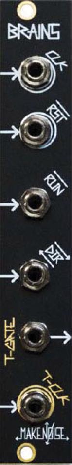
7 Panel Controls CLOCK IN: selects next stage or number to be counted on rising edge of clocke, pulse, or trigger, of at least 1V. Patch here to sequence 2. RESET IN: jumps to last touched stage on rising edge of clock, gate, pulse or trigger, of at least 1V. 3. RUN IN: Gate or logic HI (of at least 1V) will tell BRAINS to count, and thus RUN Gate or Logic LO (below 1V) will Stop BRAINS. 4. DIRection IN: Gate or logic HI (of at least 1V) tells BRAINS to count ForWarD Gate or Logic LO (below 1V) tells BRAINS to count BackWarD. 5. Touch-GATE OUT: Generates Gate HI, 10V when connected Pressure Points is touched. 6. Touch-CLocK secondary clock activated when Pressure Points is touched.
8 7 BRAINS is a clocked sequential binary event machine, intended to be connected to tactile controllers such as the Pressure Points. Once connected, Pressure Points provides data input to BRAINS in the form of touch-selectable Reset stage and Hold stage. Pressure Points also provides the tuned voltages and Pulses per stage. BRAINS, when connected to either 1 or 2 Pressure Points, will drive the stage selection in a sequential fashion, at a rate determined by the incoming clock at CLocK IN, thus forming a 4-Step or 8-Step 3-channel analog sequencer. Binary control over Direction of the stage selection, RUN/ Stop and ReSeT are provided. Touch-GATE OUT The only output on BRAINS, producing a Gate HIGH signal whenever the connected Pressure Points is touched. Touch-CLocK IN Serves a dual purpose. Used without a Master Clock applied to the CLocK IN, Events initiated by touching Pressure points will be Quantized to the timing signal applied to Touch-CLocK IN. When used along with the CLocK IN, a secondary sequence will be initiated whenever Pressure Points is touched, where the length and timing is determined by the relationship of the Touch-CLocK to the Master CLocK. Even divisions of the Master CLocK will produce tame variations of the main sequence. Non-Synchronized clocks will produce???
9 Tips & Tricks 8 Single Shot: Patch any one of the 3 tuned voltage outputs to RUN IN. Set all pots in the corresponding row to full CW. Sequence should play through all stages. Now set the pot at the stage where you want the sequence to stop, Full CCW. BRAINS counts to this stage and stops. Touching any stage other than the stage where the sequence is stopped, will run the sequence until the stop stage is reached. Knight Rider KIT Style sequencing: with sequence running, patch the Gate OUT from Stage 8 to the Trigger IN of MATHS CH. 4. Take EOC OUT from MATHS, patch to BRAINS DIRection IN. Set MATHS CH. 4 Rise to NOON, FALL to Full CW and Response to LINear. Patch Gate OUT from Stage 1 to MATHS CH. 4 BOTH Control IN. Sequence should travel back and forth like KIT car from Knight Rider. Voltage Controlled Pendulum: With sequence running, patch the Gate OUT from Stage 8 (or 4, or?) to the Trigger IN of MATHS CH. 4. Take EOC OUT from MATHS, patch to BRAINS DIRection IN. Set MATHS CH. 4 Rise to NOON, FALL to 3 o' CLock and Response to LINear. Sequence will probably be traveling BWD at this point, but it really depends upon the rate of the incoming clock at BRAIN CLK IN. By setting or modulating the FALL parameter of CH. 4, you will have control over the direction of the sequence and how long sequence travels in that direction. Touch Controlled Pattern Length: With sequence running, patch the Gate OUT from Stage 8, to BRAINS Reset IN. Touch the plate of the stage that will be the start of the sequence. Sequence will now run to stage 8, and return to last touched stage, effectively giving you touch control of sequence length. Touch Controlled JUMP: With a sequence running, patch the Gate OUT from any of the middle Stages of Pressure Points (3, 4, 5, 6), to BRAINS ReSeT IN. Touch the plate of the stage AFTER the one with Gate applied to Reset IN. Watch sequencer jump over stage. Stack multiple stages to Reset for longer jumps or multi-jumps.
10 Tips & Tricks (cont d) 9 Roland m 185 Style HOLDs: With sequence running patch same clock to Envelope Generator (MATHS CH. 1 ), patch resulting envelope to LPG (QMMG CH. 1). Apply VCO being driven by the sequencer to LPG. Mult same clock signal to Doepfer A-160 Clock Divider or RCD (Gates option set to ON). Using /8, /16, /32 will result in differenthold patterns where, using /16 for example, sequencer runs to stage 4 and holds, runs to stage 8 and holds. If available, a trigger sequencer clocked by a division of the master clock could be used to program the HOLDs instead of the clock divider. Buchla 250e Style Movement: Patch MATHS CH. 1 EOR to Clock IN, BRAINS. Set MATHS to Cycle, Rise panel control to NOON, Fall will set upper limit of clock rate. Sequence should be running. Patch the bottommost row of Tuned Voltages from Pressure Points, to MATHS CH. 1 Fall Control IN. Set all potentiometers in corresponding row to Full CCW. Sequence is now running at the upper limit (fastest) tempo/ rate. This Row of pots is like the INNER row of pots on the 250e, each setting their corresponding stage's length. As you set any stage's pot furthercw, the length of that stage will increase. The other two rows of pots in the PP/ BRAINS system are used like the OUTER row of pots on the 250e, and at their outputs you will find the Arbitrary Function quantized to the Master CLocK. UEG, MARF, ARF like: Begin with the Buchla 250e Style Movement patch. Now patch the output of the middle row of Tuned Voltages to MATHS CH. 4 Signal IN. Set Rise and Fall panel controls to NOON. Set Response to LINear. Signal OUT on MATHS CH. 4 will be your CV output, patch it to VCO, VCA, VCF, you know the game! Mult the bottommost row of Tuned Voltages from Pressure Points (the same row controlling stage length), to MATHS CH. 3 IN. Set CH. 3 Scale/ Inversion to Full CCW. Apply output of CH. 3 to MATHS CH. 4 BOTH Control IN. Sequence will run at a rate determined by the bottomrow. The control signal generated by the sequence will be "interpolated" according to the length of the stage as set by the bottom most row of PP/ BRAINS. Combine this patch with Single Shot patch to achieve a touch triggered multi-stage envelope.
Limited WARRANTY: Make Noise implies and accepts no responsibility for harm to person or apparatus caused through operation of this product.
 v2.5 2 BRAINS Limited Warranty ----------------------------------------------------3 Installation --------------------------------------------------4 Jumpers and Cable Connections --------------------------------5
Pressure Points. v. 2.5
 Pressure Points v. 2.5 2 Pressure Points FCC-------------------------------------------------------------------3 Limited Warranty ----------------------------------------------------4 Installation ----------------------------------------------------5
Spiratone FCC: Limited Warranty:
 SpirA tone v. 2.3 1 Spiratone FCC: -------------------------------------------------------------------2 Limited Warranty: ----------------------------------------------------3 Installation: ---------------------------------------------------------4
ROSIE Limited Warranty Installation
 v2.3 2 ROSIE Limited Warranty -----------------------------------------------------3 Installation ----------------------------------------------------------------4 Panel Controls ---------------------------------------------------------------5
WOGGLEBUG Limited Warranty Installation
 v2.5 2 WOGGLEBUG Limited Warranty ----------------------------------------------------3 Installation --------------------------------------------------4 Panel Controls --------------------------------------------------------5
Limited WARRANTY: Make Noise implies and accepts no responsibility for harm to person or apparatus caused through operation of this product.
 Rosie Limited WARRANTY: Make Noise warrants this product to be free of defects in materials or construction for a period of one year from the date of purchase (proof of purchase/invoice required). Malfunction
Table of Contents: ECHOPHON
 v2.6 Table of Contents: 2 ECHOPHON FCC -----------------------------------------------------3 Limited Warranty ----------------------------------------4 Installation --------------------------------------------------5
QUAD LFO MANUAL V SE 14TH AVENUE PORTLAND OR USA
 www.malekkoheavyindustry.com 814 SE 14TH AVENUE PORTLAND OR 97214 USA TABLE OF CONTENTS SPECIFICATIONS 1 INSTALLATION 2 DESCRIPTION 3 CONTROLS 4-6 USING QUAD LFO WITH VARIGATE 8+ AND VARIGATE 4+ 7 WARRANTY
QUAD ENVELOPE MANUAL V.1
 www.malekkoheavyindustry.com 814 SE 14TH AVENUE PORTLAND OR 97214 USA TABLE OF CONTENTS SPECIFICATIONS 1 INSTALLATION 2 DESCRIPTION 3 CONTROLS 4-6 MEASUREMENTS 7 USING QUAD ENVELOPE WITH VARIGATE 8+ AND
VARIGATE 4+ MANUAL V.1
 www.malekkoheavyindustry.com 814 SE 14TH AVENUE PORTLAND OR 97214 USA TABLE OF CONTENTS SPECIFICATIONS 1 INSTALLATION 2 DESCRIPTION 3 OVERVIEW 4-5 PROGRAMMING GATES PER STEP 6 PROGRAMMING CV/NOTES PER
TEMPI FCC: Limited Warranty:
 v2.5 1 TEMPI FCC: ------------------------------------------------------------------2 Limited Warranty: -------------------------------------------------3 Installation: ----------------------------------------------------------4
Polyend Poly Polyphonic MIDI to CV Converter User Manual
 Polyend Poly Polyphonic MIDI to CV Converter User Manual Made in Poland polyend.com Polyend Poly Polyphonic MIDI to CV Converter in the Eurorack format Poly is probably the easiest entry point for exploring
Table of Contents. FCC Limited Warranty Installation
 Table of Contents 2 3 4 5 6 7 8 10 13 14 16 21 22 28 29 31 FCC Limited Warranty Installation Overview Getting Started with René Panel Controls and Inputs/Outputs Clocking René CV and Page Programming Grids
TEMPI FCC Limited Warranty
 v2.7 2 TEMPI FCC ------------------------------------------------------------------3 Limited Warranty -------------------------------------------------4 Installation ----------------------------------------------------------5
Quad Clock Distributor (QCD) from 4ms Company
 from 4ms Company") Quad Clock Distributor (QCD) from 4ms Company Eurorack Module User Manual v1.0 (2013-12-09) The Quad Clock Distributor (QCD) from 4ms Company is a four channel Voltage Controlled Clock Divider/Multiplier
Quad Clock Distributor (QCD) from 4ms Company Eurorack Module User Manual v1.0 (2013-12-09) The Quad Clock Distributor (QCD) from 4ms Company is a four channel Voltage Controlled Clock Divider/Multiplier
Please contact with any questions, needs & comments... otherwise go MAKE NOISE.
 soundhack ECHOPHON Limited WARRANTY: Make Noise warrants this product to be free of defects in materials or construction for a period of two years from the date of manufacture. Malfunction resulting from
ALGORHYTHM. User Manual. Version 1.0
 !! ALGORHYTHM User Manual Version 1.0 ALGORHYTHM Algorhythm is an eight-step pulse sequencer for the Eurorack modular synth format. The interface provides realtime programming of patterns and sequencer
makenoisemusic.com Make Noise Co., 414 Haywood Road, Asheville, NC 28806
 v. 2. This device complies with Part 15 of the FCC Rules. Operation is subject to the following two conditions: (1) this device may not cause harmful interference, and (2) this device must accept any interference
NAVIGATOR OWNER S MANUAL
 OWNER S MANUAL UNCHARTED WATERS, NEW HORIZONS Making shapes spin and move is notoriously difficult for pattern synthesis based only on oscillators synchronized to horizontal and vertical frequency ranges.
Shifty Manual v1.00. Shifty. Voice Allocator / Hocketing Controller / Analog Shift Register
 Shifty Manual v1.00 Shifty Voice Allocator / Hocketing Controller / Analog Shift Register Table of Contents Table of Contents Overview Features Installation Before Your Start Installing Your Module Front
Proper installation of included power cable on module. Please note the RED BAND.
 PHONOGENE 1 Installation: The Make Noise Phonogene is an electronic signal processor/ generator requiring 70mA of +/-12V regulated power and properly formatted distribution receptacle to operate. It is
Oberkorn User Manual. Analogue Sequencer. Analogue Solutions
 Oberkorn User Manual Analogue Sequencer Analogue Solutions CONTENTS What is an analogue sequencer?... 4 That s all very well (and technical) but what would I use it for?... 4 ABOUT THIS MANUAL AND ABOUT
Description. Never run out of envelopes again.
 Contour Description Never run out of envelopes again. Contour is a quad envelope generator. Each channel has looping, CV over attack and decay, as well as unique chaining capabilities. This makes for the
FCC. to operate the equipment.
 v2.5 2 Table of Contents: Morphagene FCC------------------------------------------------------------------3 Limited Warranty-------------------------------------------------4 Installation----------------------------------------------------------5
Shifty Manual. Shifty. Voice Allocator Hocketing Controller Analog Shift Register Sequential/Manual Switch. Manual Revision:
 Shifty Voice Allocator Hocketing Controller Analog Shift Register Sequential/Manual Switch Manual Revision: 2018.10.14 Table of Contents Table of Contents Compliance Installation Installing Your Module
BINARY Zone. BLACET RESEARCH MODEL BZ2300 Binary Zone Module. User Manual
 BINARY Zone BLACET RESEARCH MODEL BZ2300 Binary Zone Module User Manual Blacet Research 15210 Orchard Rd Guerneville CA 95446 blacet@blacet.com http://www.blacet.com 707-869-9164 Contents Copyright. Reproduction
// K4815 // Pattern Generator. User Manual. Hardware Version D-F Firmware Version 1.2x February 5, 2013 Kilpatrick Audio
 // K4815 // Pattern Generator Kilpatrick Audio // K4815 // Pattern Generator 2p Introduction Welcome to the wonderful world of the K4815 Pattern Generator. The K4815 is a unique and flexible way of generating
KAMIENIEC. analog resonant phase rotator. Model of operator s manual rev. 1977/1.0
 KAMIENIEC analog resonant phase rotator operator s manual rev. 1977/1.0 Model of 1977 module explained 20 SALUT Thank you for purchasing this Xaoc Devices product. Kamieniec is an analog signal processing
4ms Quad Pingable LFO
 4ms Quad Pingable LFO Eurorack Module User Manual v2013-04-04 (pre-release) The Quad Pingable LFO (QPLFO) from 4ms Company is a compact, playable quad modulation source of four independent and identical
Plog rev 1.0 MANUAL Overview
 Overview The Intellijel Plog is a voltage controllable digital logic device designed for musical applications. It is primarily intended to create controllable patterns from gate/ pulse sources like clocks
First things first. Visit us:
 Flight Plan v. 1.2 First things first RTFM be so kind and read the manual. It will provide you with the information you need to fully indulge in the module you just purchased for which we like to thank
Tetrapad Manual. Tetrapad. Multi-Dimensional Performance Touch Controller. Firmware: 1.0 Manual Revision:
 Tetrapad Multi-Dimensional Performance Touch Controller Firmware: 1.0 Manual Revision: 2017.11.15 Table of Contents Table of Contents Overview Installation Before Your Start Installing Your Module Panel
Written by Jered Flickinger Copyright 2019 Future Retro
 Written by Jered Flickinger Copyright 2019 Future Retro www.future-retro.com 2 TABLE OF CONTENTS Page 4 - Overview Page 5 Controls Page 6 Inputs and Outputs Page 7 MIDI Page 8 Jumper Settings Page 9 Standalone
randomrhythm Bedienungsanleitung User Guide
 randomrhythm Bedienungsanleitung User Guide EN Foreword Whether random really exists or is just an illusion, shall be discussed by philosophers and mathematicians. At VERMONA, we found a possibility to
Noise Tools 1U Manual. Noise Tools 1U. Clock, Random Pulse, Analog Noise, Sample & Hold, and Slew. Manual Revision:
 Noise Tools 1U Clock, Random Pulse, Analog Noise, Sample & Hold, and Slew Manual Revision: 2018.09.13 Table of Contents Table of Contents Compliance Installation Before Your Start Installing Your Module
Noise Tools 1U Manual. Noise Tools 1U. Clock, Random Pulse, Analog Noise, Sample & Hold, and Slew. Manual Revision:
 Noise Tools 1U Clock, Random Pulse, Analog Noise, Sample & Hold, and Slew Manual Revision: 2018.05.16 Table of Contents Table of Contents Overview Installation Before Your Start Installing Your Module
// K4815 // Pattern Generator. User Manual. Hardware Version D/E Firmware Version 1.1x February 16, 2011 Kilpatrick Audio
 // K4815 // Pattern Generator Kilpatrick Audio // K4815 // Pattern Generator 2p Introduction Welcome to the wonderful world of the K4815 Pattern Generator. The K4815 is a unique and flexible way of generating
Charlie Foxtrot Features include:
 Charlie Foxtrot is a digital buffer/granular pedal with both autocapture and manual-capture of the input signal. Playback and capture can be manipulated through several parameters: The six knobs control
Revision 1.2d
 Specifications subject to change without notice 0 of 16 Universal Encoder Checker Universal Encoder Checker...1 Description...2 Components...2 Encoder Checker and Adapter Connections...2 Warning: High
Synthesis Technology E102 Quad Temporal Shifter User Guide Version 1.0. Dec
 Synthesis Technology E102 Quad Temporal Shifter User Guide Version 1.0 Dec. 2014 www.synthtech.com/euro/e102 OVERVIEW The Synthesis Technology E102 is a digital implementation of the classic Analog Shift
TEST 3 EURORACK V/mA METER INTRODUCTION BUILD INSTRUCTIONS
 INTRODUCTION Test 3 is a purpose-designed tool for measuring voltages and currents in your Eurorack system. This means that just a single circuit board or module can now replace a convoluted test setup
A-134 VC Panning Module
 doepfer System A - 100 Voltage Controlled Panning A-134 1. Introduction A-134 VC Panning Module CV 1 Pan Module A-134 (PAN) is designed to provide voltagecontrolled panning for audio signals. It can equally
Dual Looping Delay from 4ms Company Eurorack Module User Manual 1.1c (2017-January-11) Firmware version 5
 Firmware version 5") Dual Looping Delay from 4ms Company Eurorack Module User Manual 1.1c (2017-January-11) Firmware version 5 The Dual Looping Delay (DLD), designed by 4ms Company and Gary Hall, is an advanced audio processor
Dual Looping Delay from 4ms Company Eurorack Module User Manual 1.1c (2017-January-11) Firmware version 5 The Dual Looping Delay (DLD), designed by 4ms Company and Gary Hall, is an advanced audio processor
LS1lightstrip User s Manual. Introduction Care and feeding Specifications. soundmachines user manual 1 LS1lightstrip
 User s Manual Introduction Care and feeding Specifications soundmachines user manual 1 Introduction The is a capacitive slider that will generate CV and GATE signals along with the movement of your finger
Rhythm. Pattern Generator
 Rhythm Pattern Generator Description The Rhythm is a 4 channel pattern generator with BPM display. It ships with a multitude of genre-oriented rhythms that can be altered on a per channel basis. With each
ADE-60 4:4 MIX UTILITY
 ADE-60 4:4 MIX UTILITY Cascading, 4-Channel, Mix & CV Utility with user-configurable options for 2x Gain, Attenuversion, Biasing & CV. 2017 Abstract Data Ltd. http://www.abstractdata.biz Version 1.0.2
1. SAFETY & WARRANTY 2 2. WHAT IS CGM 3 3. SYSTEM SETUP (LINKING) Master to Group(s) Group to Channel(s) 3 4. CONNECT THE POWER 4
 Master to Group(s) Group to Channel(s) 3 4. CONNECT THE POWER 4") CGM CREATIVE MIXER 1. SAFETY & WARRANTY 2 2. WHAT IS CGM 3 3. SYSTEM SETUP (LINKING) 3 3.1. Master to Group(s) 3 3.2. Group to Channel(s) 3 4. CONNECT THE POWER 4 4.1. Which channel module should be powered
CGM CREATIVE MIXER 1. SAFETY & WARRANTY 2 2. WHAT IS CGM 3 3. SYSTEM SETUP (LINKING) 3 3.1. Master to Group(s) 3 3.2. Group to Channel(s) 3 4. CONNECT THE POWER 4 4.1. Which channel module should be powered
ANTUMBRA FADE MANUAL
 ANTUMBRA FADE MANUAL TABLE OF CONTENTS 01. INSTALLATION 4 02. BACK 5 03. FRONT 6 04. USE 7 05. LINK 8 06. BILL OF MATERIALS 9 07. BUILD NOTES 10 08. BACK 11 09. FRONT 14 10. MODIFICATION 15 11. FINISHED
1. Introduction. A-160 CLOCK DIVIDER Trig. In Res. In. doepfer System A Clock Divider A-160
 doepfer System A - 100 Clock Divider 1. troduction Module (Clock Divider) is a frequency divider for clock signals, designed to be a source of lower frequencies, particularly for rhythm uses. The Trigger
USER MANUAL FOR THE ANALOGIC GAUGE FIRMWARE VERSION 1.1
 by USER MANUAL FOR THE ANALOGIC GAUGE FIRMWARE VERSION 1.1 www.aeroforcetech.com Made in the USA! WARNING Vehicle operator should focus primary attention to the road while using the Interceptor. The information
PSM-003. Micro Polarization Controller/Scrambler. User Guide
 PSM-003 Micro Polarization Controller/Scrambler User Guide Version: 1.0 Date: August 23, 2012 General Photonics, Incorporated is located in Chino California. For more information visit the company's website
A BBD replacement and adjustment procedure
 A-188-1 BBD replacement and adjustment procedure The following steps have to be carried out with the unpowered A-188-1 module (i.e. the module is not connected to the A-100 bus board or the module is connected
Start/Stop works in each mode, and puts the pattern back to the starting point step 1 of the current pattern.
 Sequencer Modes In all six modes the playing of the sequencer is guaranteed. You can change the modes, while the sequencer is running. Switching into another mode, takes place after the last step of the
ADE-32 OCTOCONTROLLER
 ADE-32 OCTOCONTROLLER Control, Modulation, Triggering and Pattern module with 12 Output Types individually assignable to 8 simultaneous Outputs. USER GUIDE 2016 Abstract Data Ltd. http://www.abstractdata.biz
USER MANUAL FOR THE ANALOGIC GAUGE FIRMWARE VERSION 1.0
 by USER MANUAL FOR THE ANALOGIC GAUGE FIRMWARE VERSION 1.0 www.aeroforcetech.com Made in the USA! WARNING Vehicle operator should focus primary attention to the road while using the Interceptor. The information
LAB #4 SEQUENTIAL LOGIC CIRCUIT
 LAB #4 SEQUENTIAL LOGIC CIRCUIT OBJECTIVES 1. To learn how basic sequential logic circuit works 2. To test and investigate the operation of various latch and flip flop circuits INTRODUCTIONS Sequential
Registers and Counters
 Registers and Counters Clocked sequential circuit = F/Fs and combinational gates Register Group of flip-flops (share a common clock and capable of storing one bit of information) Consist of a group of
Using Sliders with the 4201-B Lighting Controller Application Note June 26, 2008
 Using Sliders with the 4201-B Lighting Controller Application Note June 26, 2008 This application note will discuss ways of using potentiometers (sliders or normal rotary volume control type) with the
bindubba1 The only real rule with nonlinearcircuits panels is BLUE jacks = INPUT RED jacks = OUTPUT
 The two sequencers are happy to operate independently of each other but for greater entertainment and general synchronised lunacy it is good to couple them. In which case usually bindubba1 is the top and
Operating Manual Ver.1.1
 Johnson Counter Operating Manual Ver.1.1 An ISO 9001 : 2000 company 94-101, Electronic Complex Pardesipura, Indore- 452010, India Tel : 91-731- 2570301/02, 4211100 Fax: 91-731- 2555643 e mail : info@scientech.bz
5U Oakley Modular Series
 Oakley Sound Systems 5U Oakley Modular Series VC-LFO Low Frequency Oscillator PCB Issue 2 User Manual V2.0.04 Tony Allgood B.Eng PGCE Oakley Sound Systems CARLISLE United Kingdom The suggested panel layout
Tiptop audio z-dsp.
 Tiptop audio z-dsp www.tiptopaudio.com Introduction Welcome to the world of digital signal processing! The Z-DSP is a modular synthesizer component that can process and generate audio using a dedicated
AB-114 / AB-202 AB-404 / AB-301 AB-T2454 Multi-room audio distribution system AB-202
 by By C HANNEL V ISION system AB-114 / AB-404 / AB-01 AB-T2454 Multi-room audio distribution system IN OUT 1 2 4 WHT/ WHT/ L AUDIO R 12VDC A-BUS OUTPUT IR IR EMITTERS C HANNEL V ISION 24 Fischer Avenue
ECE 5765 Modern Communication Fall 2005, UMD Experiment 10: PRBS Messages, Eye Patterns & Noise Simulation using PRBS
 ECE 5765 Modern Communication Fall 2005, UMD Experiment 10: PRBS Messages, Eye Patterns & Noise Simulation using PRBS modules basic: SEQUENCE GENERATOR, TUNEABLE LPF, ADDER, BUFFER AMPLIFIER extra basic:
oberkorn3 analogue sequencer user manual analogue sequencer user manual ANALOGUE SOLUTIONS oberkorn mkiii e&oe (c)
") oberkorn3 analogue sequencer user manual analogue sequencer user manual ANALOGUE SOLUTIONS oberkorn mkiii e&oe (c) 10-2006 1 Contents Intro - OBERKORN - Professional Analogue Sequencer...4 About Analogue
oberkorn3 analogue sequencer user manual analogue sequencer user manual ANALOGUE SOLUTIONS oberkorn mkiii e&oe (c) 10-2006 1 Contents Intro - OBERKORN - Professional Analogue Sequencer...4 About Analogue
Sequential Logic and Clocked Circuits
 Sequential Logic and Clocked Circuits Clock or Timing Device Input Variables State or Memory Element Combinational Logic Elements From combinational logic, we move on to sequential logic. Sequential logic
BER MEASUREMENT IN THE NOISY CHANNEL
 BER MEASUREMENT IN THE NOISY CHANNEL PREPARATION... 2 overview... 2 the basic system... 3 a more detailed description... 4 theoretical predictions... 5 EXPERIMENT... 6 the ERROR COUNTING UTILITIES module...
TRIPLETT. PairMaster. Lan Cable Test Set. Instruction Manual
 TRIPLETT PairMaster Lan Cable Test Set Instruction Manual The PairMaster LAN CABLE TEST SET INSTRUCTION MANUAL IMPORTANT SAFETY INSTRUCTIONS SAVE THESE INSTRUCTIONS Before using the PairMaster, read all
GUIDE TO ASSEMBLY OF ERICA SYNTHS DELAY MODULE
 If you are reading this, most probably, you are about to build Erica Synths DIY DELAY module. The module is 4mm deep, skiff friendly, has solid mechanical construction and doesn t require wiring. Erica
Lecture 8: Sequential Logic
 Lecture 8: Sequential Logic Last lecture discussed how we can use digital electronics to do combinatorial logic we designed circuits that gave an immediate output when presented with a given set of inputs
16-BIT LOAD CELL/DUAL STATUS INPUT
 16-BIT LOAD CELL/DUAL STATUS INPUT On-board Excitation. +5VDC, (120mA). State-of-the-art Electromagnetic Noise Suppression Circuitry. Ensures signal integrity even in harsh EMC environments. Optional Excitation
Intelligent Quantizer and Interval Generator
 µscale Intelligent Quantizer and Interval Generator Manual Revision: 2018.02.16 Table of Contents Table of Contents Overview Features Installation Before Your Start Installing Your Module Front Panel Controls
Modcan Touch Sequencer Manual
 Modcan Touch Sequencer Manual Normal 12V operation Only if +5V rail is available Screen Contrast Adjustment Remove big resistor if using with PSU with 5V rail Jumper TOP VEIW +5V (optional) +12V } GND
VideoEase HDMI 3x1 Switcher Kit (110V) Installation Guide
 Installation Guide") VideoEase HDMI 3x1 Switcher Kit 500410 (110V) Installation Guide P/N: 94-00628-A SE-000627-A Copyright Notice : Copyright 2008 MuxLab Inc. All rights reserved. Printed in Canada. No part of this publication
VideoEase HDMI 3x1 Switcher Kit 500410 (110V) Installation Guide P/N: 94-00628-A SE-000627-A Copyright Notice : Copyright 2008 MuxLab Inc. All rights reserved. Printed in Canada. No part of this publication
PCM ENCODING PREPARATION... 2 PCM the PCM ENCODER module... 4
 PCM ENCODING PREPARATION... 2 PCM... 2 PCM encoding... 2 the PCM ENCODER module... 4 front panel features... 4 the TIMS PCM time frame... 5 pre-calculations... 5 EXPERIMENT... 5 patching up... 6 quantizing
Audio Interface II Manual. Audio Interface II. Eurorack <-> Line Level Audio Interface. Manual Revision:
 Audio Interface II Eurorack Line Level Audio Interface Manual Revision: 2018.09.13 Table of Contents Table of Contents Compliance Installation Installing Your Module Overview Features Front Panel Controls
Cockpit. Flight plan 1.1
 Cockpit Flight plan 1.1 First things first RTFM be so kind and read the manual. It will provide you with the information you need to fully indulge in the module you just purchased for which we like to
RS232 settings are internally definable via jumper blocks, to accommodate interfacing with a wide range of control products.
 Appendix C RS232 Protocol RS232 settings are internally definable via jumper blocks, to accommodate interfacing with a wide range of control products. Baud rate 9600 or 19200 Echo status AUTO or REQUEST
CADET I SYNC GENERATOR OWNER S MANUAL
 OWNER S MANUAL ABOUT THE CADET SERIES The practice of analog video synthesis has an inspiring legacy of innovators, sharers, and doers. In the early 70's, Dan Sandin released the hardware documentation
RD RACK MOUNT DIMMER OWNERS MANUAL VERSION /09/2011
 RD - 122 RACK MOUNT DIMMER OWNERS MANUAL VERSION 1.3 03/09/2011 Page 2 of 14 TABLE OF CONTENTS UNIT DESCRIPTION AND FUNCTIONS 3 POWER REQUIREMENTS 3 INSTALLATION 3 PLACEMENT 3 POWER CONNECTIONS 3 OUTPUT
R H Y T H M G E N E R A T O R. User Guide. Version 1.3.0
 R H Y T H M G E N E R A T O R User Guide Version 1.3.0 Contents Introduction... 3 Getting Started... 4 Loading a Combinator Patch... 4 The Front Panel... 5 The Display... 5 Pattern... 6 Sync... 7 Gates...
CG-1 CAMERA-GUARD INSTRUCTION BOOK IB647501
 CG-1 CAMERA-GUARD INSTRUCTION BOOK IB647501 TABLE OF CONTENTS DESCRIPTION 2 MOUNTING INSTRUCTIONS 2 HOW TO CABLE THE CG-1 2 POWER SUPPLY INSTALLATION 3 OPERATION 3 CARE AND MAINTENANCE 3 APPLICATIONS (WHERE
Digital Systems Laboratory 3 Counters & Registers Time 4 hours
 Digital Systems Laboratory 3 Counters & Registers Time 4 hours Aim: To investigate the counters and registers constructed from flip-flops. Introduction: In the previous module, you have learnt D, S-R,
AI-1616L-LPE. Features. High-precision Analog input board (Low Profile size) for PCI Express AI-1616L-LPE 1. Ver.1.02 Ver.1.01
 for PCI Express AI-1616L-LPE 1. Ver.1.02 Ver.1.01") High-precision Analog input board (Low Profile size) for PCI Express AI-1616L-LPE This product is a multi-function, PCI Express bus-compliant interface board that incorporates high-precision 16-bit analog
High-precision Analog input board (Low Profile size) for PCI Express AI-1616L-LPE This product is a multi-function, PCI Express bus-compliant interface board that incorporates high-precision 16-bit analog
EMT 125 Digital Electronic Principles I CHAPTER 6 : FLIP-FLOP
 EMT 125 Digital Electronic Principles I CHAPTER 6 : FLIP-FLOP 1 Chapter Overview Latches Gated Latches Edge-triggered flip-flops Master-slave flip-flops Flip-flop operating characteristics Flip-flop applications
Mal-2 assembly guide v1.0
 Mal-2 assembly guide v.0 SONIC POTIONS Schematic and BOM The BOM can be found on Google Docs Prepare the PCB Separate the PCBs using some pliers. PCB We start with the lower PCB and assemble it beginning
Pixie Construction Notes
 Pixie Construction Notes PCB V2a February 4 th 2015 Please note that this document is still currently under revision and we apologise for any errors or omissions. Readers should feel free to e-mail any
The outputs are formed by a combinational logic function of the inputs to the circuit or the values stored in the flip-flops (or both).
.") 1 The outputs are formed by a combinational logic function of the inputs to the circuit or the values stored in the flip-flops (or both). The value that is stored in a flip-flop when the clock pulse occurs
1 The outputs are formed by a combinational logic function of the inputs to the circuit or the values stored in the flip-flops (or both). The value that is stored in a flip-flop when the clock pulse occurs
AD9884A Evaluation Kit Documentation
 a (centimeters) AD9884A Evaluation Kit Documentation Includes Documentation for: - AD9884A Evaluation Board - SXGA Panel Driver Board Rev 0 1/4/2000 Evaluation Board Documentation For the AD9884A Purpose
INSTRUCTION MANUAL FOR MODEL IOC534 LOW LATENCY FIBER OPTIC TRANSMIT / RECEIVE MODULE
 210 South Third Street North Wales, PA USA 19454 (T) 215-699-2060 (F) 215-699-2061 INSTRUCTION MANUAL FOR LOW LATENCY FIBER OPTIC TRANSMIT / RECEIVE MODULE i TO THE CUSTOMER Thank you for purchasing this
autotwo Automatic Mixer Operation Manual
 autotwo Automatic Mixer Operation Manual Biamp Systems 9300 S.W. Gemini Drive Beaverton, OR 97008 USA +1.503.641.7287 www.biamp.com TABLE OF CONTENTS Front Panel Rear Panel Logic Outputs Specifications
Decade Counters Mod-5 counter: Decade Counter:
 Decade Counters We can design a decade counter using cascade of mod-5 and mod-2 counters. Mod-2 counter is just a single flip-flop with the two stable states as 0 and 1. Mod-5 counter: A typical mod-5
D Latch (Transparent Latch)
") D Latch (Transparent Latch) -One way to eliminate the undesirable condition of the indeterminate state in the SR latch is to ensure that inputs S and R are never equal to 1 at the same time. This is done
D Latch (Transparent Latch) -One way to eliminate the undesirable condition of the indeterminate state in the SR latch is to ensure that inputs S and R are never equal to 1 at the same time. This is done
Linear encoders without bearings incremental System for linear motion feedback
 Features Robust magnetic sensing method Output signals A 90 B with index signal Output circuits: HTL/push-pull and TTL/RS422 Resolution up to 5 µm (4-times evaluation) Non-contact, wear-free sensing system
By CHANNEL VISION. Flush Mount Amplifier A0350
 Spkrs Local In IR In 24VDC A0350 10 The A0350 can be used with Channel Vision s CAT5 audio hubs to provide a powerful 50Watts per channel in the listening zone. Alternatively, the A0350 can be added to
Rebis Audio Ltd. RA226 Digital Sampler User Guide
 Rebis Audio Ltd. RA226 Digital Sampler User Guide CONTENTS Page Caution 2 Powering Up 2 Controls 3, 4 Detailed Description Input Level Set 5 Recording 5 Sampling 5 Multiple Samples 6 Editing 6 Playback
Troubleshooting Your Design with the TDS3000C Series Oscilloscopes
 Troubleshooting Your Design with the 2 Table of Contents Getting Started........................................................... 4 Debug Digital Timing Problems...............................................
16 Stage Bi-Directional LED Sequencer
 16 Stage Bi-Directional LED Sequencer The bi-directional sequencer uses a 4 bit binary up/down counter (CD4516) and two "1 of 8 line decoders" (74HC138 or 74HCT138) to generate the popular "Night Rider"
SATELLITE. Universal CV Generator. Operation Manual. v2.1_ Copyright 2017 Rossum Electro-Music LLC
 SATELLITE Universal CV Generator Operation Manual v2.1_060117 Copyright 2017 Rossum Electro-Music LLC www.rossum-electro.com Contents 1. Introduction 3 2. Module Installation 4 3. Overview 5 4. How to
Registers and Counters
 Registers and Counters Clocked sequential circuit = F/Fs and combinational gates Register Group of flip-flops (share a common clock and capable of storing one bit of information) Consist of a group of