Digital Storage Oscilloscope. IDS-700 & IDS-800 Series
|
|
|
- Georgina Hopkins
- 6 years ago
- Views:
Transcription
1 Digital Storage Oscilloscope IDS-700 & IDS-800 Series Operation Manual 2003 RS Components Ltd. All rights reserved 82DS-81000MA 0
2 Table of Contents Pages 1. USAGE PRECAUTIONS AND RECOMMENDATIONS GENERAL DESCRIPTION AND FEATURES FIRST TIME OPERATION PANEL DESCRIPTION OPERATION BLOCK DIAGRAM RS-232 CONFIGURATION SPECIFICATIONS Due to continuous improvements in the IDS-706/710/720/806/810/820 Digital Storage Oscilloscopes, information contained in this manual is subject to change without notice. Contact RS Components for revisions and corrections. This document supports firmware version v1.07 and previous version RS Components Ltd. PO Box 99, Corby, Northants., NN17 9RS United Kingdom. Tel: +44 (0) Fax: +44 (0) Internet: rswww.com 1
3 1. Usage Precautions and Recommendations The following precautions are recommended to ensure your safety and to provide the best conditions for this instrument. If this equipment is used in a manner not specified by the manufacturer, the protection provided by the equipment may be impaired. Safety Terms and Symbols These terms may appear in this manual or on the product: WARNING: Warning statements identify condition or practices that could result in injury or loss of life. CAUTION: Caution statements identify conditions or practices that could result in damage to this equipment or other property. The following symbols may appear in this manual or on the equipment: DANGER ATTENTION Protective Frame Earth (ground) High Voltage Refer to Conductor or Chassis Terminal Terminal Manual Terminal 2
4 FOR UNITED KINGDOM ONLY NOTE: This lead / appliance must only be wired by competent persons WARNING: THIS APPLIANCE MUST BE EARTHED IMPORTANT: The wires in this lead are colour-coded in accordance with the following code: Green/ Yellow: Earth Blue: Neutral Brown: Live (Phase) As the colours of the wires in main leads may not correspond with the coloured marking identified in your plug/appliance, proceed as follows: The wire which is coloured Green & Yellow must be connected to the Earth terminal marked with the letter E or by the earth symbol or coloured Green or Green & Yellow. The wire which is coloured Blue must be connected to the terminal which is marked with the letter N or coloured Blue or Black. The wire which is coloured Brown must be connected to the terminal marked with the letter L or P or coloured Brown or Red. If in doubt, consult a competent electrician or contact RS Components for further advice. This cable/appliance should be protected by a suitably rated and approved HBC mains fuse: refer to the rating information on the equipment and/or user instructions for details. As a guide, cable of 0.75mm 2 should be protected by a 3A or 5A fuse. Larger conductors would normally require 13A types, depending on the connection method used. Any moulded mains connector that requires removal or replacement must be destroyed by removal of any fuse & fuse carrier and disposed of immediately, as a plug with bared wires is hazardous if engaged in live socket. Any re-wiring must be carried out in accordance with the information detailed on the wiring label, this Instruction Book and comply with current wiring regulations. 3
5 Use and Care CAUTION Do not exceed 300V peak into the channel BNC INPUTs To avoid risk of fire hazard and electrical shock, a hazardous live voltage must never be connected to the negative side (reference side) of the BNC measuring terminals. Do not place any heavy object on the instrument. Avoid severe impacts or rough handling that could damage the instrument. Use electrostatic discharge precautions while handling and making connections to the instrument. Do not place wires into the connectors of the instrument; use only the correct mating connectors and adapters. Do not block or obstruct the cooling fan vents on the side or rear panel of the instrument. 1) Disassembly of the Instrument Do not disassemble the instrument. If repair or calibration is required, contact RS Components for advice. 2) AC Power Input CAUTION The a.c.input should be within the range of selected line voltage ±10%. Ensure the correct fuse is installed prior to applying voltage for the first time For 100 V ~ 240 VAC input: Fuse rating is: Anti-surge 2A / 250V High Breaking Capacity type (HBC), 20 x 5 mm. 4
6 3) Grounding WARNING To avoid electrical shock, the power cord protective grounding conductor must be connected to earth ground. 4) Fuse Replacement WARNING For continued fire protection, replace the fuse with the specified type and rating only. Disconnect the power cord before replacing the fuse. Use a flat blade screwdriver to open the fuse drawer on the a.c. inlet socket. If the fuse has blown, there is a fault. Investigate and rectify the cause of the fault before replacing the fuse. Replace the fuse. 5) Cleaning Disconnect AC Power Cord from the instrument before cleaning. Use a soft cloth dampened in a solution of mild detergent and water. Do not allow any liquid to enter the instrument. Do not use chemicals or cleaners containing benzene, toluene, xylene, acetone or other harsh chemicals. 5
7 6) Operating Environment Use of this instrument outside the recommended operating conditions may impair the safety provided for the user. The following conditions are recommended for optimum use of the instrument - Indoor Use Altitude < 2000 m Temperature 0 to 50 C Relative Humidity < 80% No direct sunlight No strong magnetic fields Dust Free Installation Category: 300V Cat.II* Pollution degree: 2 7) Storage Environment The following conditions are recommended for optimum storage of the instrument - Indoor Temperature -20 to 70 C Relative Humidity < 80% WARNING This is a Class A product. In a domestic environment this instrument may cause radio and/or television interference in which case the user may be required to take adequate corrective measures. *: Measurement category IV is for measurement performed at the source of low-voltage installation Measurement category III is for measurement performed in the building installation Measurement category II is for measurement performed on the circuits directly connected to the low voltage installation 2. General Description and Features The IDS-706, 710, 720, 806, 810 and 820 oscilloscopes are versatile, 2 channel digital storage instruments with the following features: 60MHz, 150MHz, (250MHz for IDS-720 & 820) repetitive bandwidth and 100MSa/s sample rate per channel (25GSa/s E.T. sample rate per channel). Up to 10ns peak detection for glitch capture. 6
8 A large 5.7 mono or colour LCD display (monochrome display for IDS-706, 710, and 720, colour display for IDS-806, 810 and IDS-820). Two input channels, each with a record length of 125k points and 8 bits vertical resolution. Both channels acquire waveforms simultaneously. Time base: 1ns/div~10s/div. 6-digit frequency counter. Auto-set for quick setup operation. Three Acquisition modes: Sample, peak detect, and average mode. Cursors and 15 continuously updated automatic measurements: V hi, V lo, V max, V min, V pp, V average, V rms, V amp, rise time, fall time, duty cycle, frequency, period, positive width, negative width. 15 memory sets for front panel setting save & recall. 2 memory sets for waveform trace save & recall. FFT spectrum analysis. Two useful Program mode and Go, No-Go function are included. Advanced video and pulse width trigger. A large 8 12 divisions(menu off)waveform display graticule. RS-232, parallel printer port and USB output are included as standard on all models. 7
9 The IDS-706, 710, 720, 806, 810 & 820 advanced 32-bit microprocessor controlled Digital Storage Oscilloscopes have been designed for a wide range of applications in educational, service and industrial applications. The instruments offer a combinations of trigger control, frequency response, time base versatility and other functions to facilitate measurements and observations, which are generally only available on more expensive oscilloscopes. For ease of operation an Autoset function allows for signal related automatic setup of measuring parameters. On-screen readouts and cursor functions for voltage, frequency and frequency related measurement provide extraordinary operational convenience. Fifteen different user defined instrument settings can be saved and recalled without restriction. The built-in RS-232 serial interface allows for remote controlled operation by a PC. A six-digit frequency counter provides extra functionality. The standard USB port permits the dump of the entire contents of the instruments LCD screen to computer via specific software. A Program mode is provided to record all the necessary waveform measuring operations and replay all steps as required. The additional Go, No-Go function allows for a simple semi-automated comparison of waveforms with predetermined limits. 8
10 3. First Time Operation The following text assumes that the SAFETY section of this manual has been read carefully and understood. Each time before the instrument is put into operation, check that the oscilloscope is connected to protective earth. For this reason the power cable must be connected to the oscilloscope and the power outlet first. Next, connect the test lead(s) to the oscilloscope input(s). Check that the equipment or unit under test is switched off and connect the test lead(s) to the test point(s). Lastly, switch on the instrument and afterward the equipment or device under test. The oscilloscope is switched on by a single press of the ON/STBY button (Before depressing the ON/STBY button on the front panel, ensure the main power switch on the rear panel is switched on). After a few seconds the oscilloscope will initialize and revert to its last used operating mode. Tilt-stand: For desktop use, lock the tilt-stand in place as shown in the following diagrams: Figure 3-1: Tilt-stand operation 9

11 Probe calibration To display an undistorted waveform on an oscilloscope, the probe must be matched to the individual input impedance of each vertical amplifier. For this purpose a square wave signal with a very fast rise time and minimum overshoot should be used, as the sinusoidal contents cover a wide frequency range. The build-in compensation signal generator provides a square wave signal with a very fast rise time, and frequency of approx. 1kHz from the output socket below the LCD screen. As the square wave signals are used for probe compensation adjustment, neither the frequency accuracy nor the pulse duty factor are of importance and therefore not specified. The output provides 2V pp ±3% for a 10:1 probe. When the Y deflection coefficient is set to 50mV/div, the calibration voltage corresponds to a vertical display of 4 divisions (10:1 probe). Connect the probe to the probe calibration output and check the waveform indicates correct compensation (see Figure 3-2). If the waveform indicates over or under compensation, refer to the instructions for the probe and adjust the compensation. incorrect correct incorrect Figure 3-2: Probe compensations 10
12 AUTOSET The Autoset function provides a stable, triggered display of almost any input signal. Connect a signal to either the channel 1 or channel 2 input BNC connectors and press the AUTOSET button. Table 3-1 shows the defaults of Autoset function. Table 3-1: Defaults of Autoset function Control parameter: Acquire Acquire stop after Display style Display format Horizontal position Horizontal Scale Trigger coupling Trigger level Trigger position Trigger slope Trigger source Trigger type Vertical bandwidth Vertical coupling Vertical offset Vertical scale Modified by Autoset to: Sample RUN/STOP button only Vectors YT Centered within the graticule windows As determined by the signal frequency DC Midpoint of trace for the trigger source Center Positive Highest frequency of available channels Edge Full DC or AC (dependent on the signal) 0 V As determined by the signal level 4. Panel Description Front Panel 11
13 12

14 Display Area (1): The memory bar (500 points processed by oscilloscope)*. (2): Trigger position (T) indicator (3): Viewable area shows segment of memory bar currently displayed*. Please refer page 38 for details. (4): Run/Stop mode indicator (5): Trigger status (6): Trigger level indicator (7): Channel position indicator (8): Delay trigger indicator (9): Status display for channel 1 & 2 (10): Sample rate status readout (11): Horizontal status readout (12): Trigger source and status readout (13): Trigger type and mode readout (14): Acquisition status (15): Interface type indicator (16): Trigger Frequency counter *: The memory bar length is always 500 points under RUN mode, even when the memory length is set greater than 500 points. The oscilloscope will display 250 points or 300points (menu off) on the LCD screen waveform area. 13
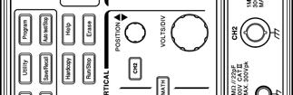
15 Vertical controls (1): Channel 1 and 2 POSITION knobs. The position control knobs adjust the vertical position of the channel 1 and channel 2 waveforms on the screen. (2): CH1, CH2 Menu pushbutton. Shows the vertical waveform function and selects the waveform on or off the screen. (3): MATH function pushbutton. Selects the various math functions available. (4): VOLTS/DIV knobs. Adjusts the vertical scale of the waveforms. Horizontal controls (1): HORI MENU. Selects the horizontal functions. (2): Horizontal POSITION knob. Adjusts waveform horizontal position on the screen. (3): TIME/DIV knob. Adjusts the horizontal scale of selected waveform. 14
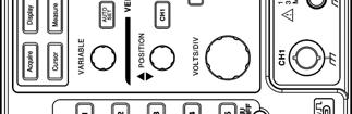
: Control the display modes. (3): Select the utility functions. (4): Sets the Program mode. (5): Select the cursor types. (6): VARIABLE knob. Multi-function knob which controls many menu functions.")
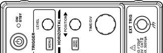
16 Trigger controls (1): The power ON/STANDBY pushbutton. (2): Selects the trigger type, source and mode. (3): Trigger level adjustment. Miscellaneous controls (1): Select the acquire modes. (2): Control the display modes. (3): Select the utility functions. (4): Sets the Program mode. (5): Select the cursor types. (6): VARIABLE knob. Multi-function knob which controls many menu functions. (7): Access the 15 automatic measurement modes. (8): AUTOSET pushbutton automatically adjusts setup values to display a signal. (9): Printout a hardcopy of the LCD display. (10): Start and stop waveform acquisition. (11): Save and recall the setups and waveforms. (12): Erases the stationary waveform display. (13): Display build-in help files on the LCD screen. (14): Stop the replay for Program mode. 15
: AC power inlet. (3): Fuse drawer. (4): SELF CAL output BNC (output range: 0~±2V DC).")
17 BNC inputs (1): The channel 1 & 2 BNC inputs receive electrical signals for display. (2): Ground. (3): Connects an external trigger signal to the oscilloscope. Rear Panel (1): Main power switch. (2): AC power inlet. (3): Fuse drawer. (4): SELF CAL output BNC (output range: 0~±2V DC). (5): GO/NO GO output BNC (open collector output, a 10μs pulse will be generated, if certain conditions is met, please refer to page 46 for details) (6): USB connector (7): Printer port (8): RS-232 port 16


18 5. Operation This chapter contains useful information about the operation of this oscilloscope. Vertical Control All vertical operations affect the selected waveform. Press the CH1, CH2, or MATH pushbutton to adjust and select the waveform scale and position. Figure 5-1: The vertical controls panel VOLTS/DIV: The VOLTS/DIV knobs adjust the vertical scale (in a sequence) of the selected waveforms (channel 1 and channel 2). POSITION: The position control knobs adjust the vertical position of the channel 1 & 2 waveforms. When the vertical position is adjusted, the channel position indicator or (located on the left side of the LCD graticule) will change position simultaneously. When the channel position indicator reaches the vertical border (top or bottom) of the LCD graticule, the indicator will change shape to, or,. The vertical scale information will also be displayed on the LCD screen. If the position of channel 1 (or channel 2) is changed, the vertical position will be displayed above the status display area of the screen (1). Figure 5-2: Operating the position knob 17
 is turned on, the CH1 (or CH2) button will be illuminated, and vice versa. Coupling / / : Press the F1 softkey to select AC ( ) or DC ( ) coupling, or ground ( ).")
19 CH1, CH2: The vertical menu contains the following items when channel 1 or channel 2 is selected. These two pushbuttons also switch the waveform display of channel 1 or channel 2 on or off. When channel 1 (or channel 2) is turned on, the CH1 (or CH2) button will be illuminated, and vice versa. Coupling / / : Press the F1 softkey to select AC ( ) or DC ( ) coupling, or ground ( ). Invert On/Off: Press the F2 softkey to select to turn (waveform) invert on or off. Bw Limit On/Off: Press the F3 softkey to switch between 20MHz or full bandwidth. Probe 1/10/100: Press the F4 softkey to select the probe attenuation 1, 10, or 100 as appropriate. Impedance 1MΩ: Input impedance display. MATH: Select a formula from the math menu: CH1+CH2, CH1-CH2 or FFT (Fast Fourier Transform). You can convert a time-domain signal into its frequency components by an advanced FFT math function. The Math menu contains the following items by pressing F1 softkey after math function is selected. The display of the mathematical waveform can be disabled by pressing MATH pushbutton again. CH1+CH2: Waveform of channel 1 plus waveform of channel 2. Figure 5-3: Operating the math function (Channel 1 + channel 2) CH1-CH2: Algebraic sum of channel 1 and channel 2. The position of CH1+CH2/CH1-CH2 mathematical waveform can be adjusted by rotating the VARIABLE knob. The math position indicator (located on the left side of the LCD graticule) will change the position simultaneously. The information of mathematical division and units will also be displayed on the math menu bar. FFT: The details of FFT operations are as follows: FFT Operation: Push the MATH button to select the FFT function. The Source Channel and Window algorithm can be selected. Press the MATH pushbutton again to disable FFT spectrum 18
20 display. Source CH1/CH2: Selects the channel assigned to the FFT spectrum. Window Rectangular/Blackman/Hanning/Flattop: Window Rectangular: Transform to rectangular windowing mode. This windowing mode is suitable for transient analysis. Window Blackman: Transform to Blackman window mode. The peak resolution of Blackman window mode is not as fine as Hanning mode, however, the response shape flares-out less at low levels and rejection of sidelobes is better. Window Hanning: Transform to Hanning window mode. Higher frequency resolution is available when using this mode. Window Flattop: Transform to flattop windowing mode. This mode can obtain higher magnitude accuracy. 19
21 Position: Adjust the FFT position on the display area by rotating the VARIABLE knob. The math position indicator which located on the left side of LCD screen always points to 0 db approximately, where 0dB is defined as 1Vrms. Unit/div 20/10/5/2/1 db: Press F5 softkey to expand the FFT spectrum vertically. Expansion factors are 20dB/Div, 10dB/Div, 5dB/Div, 2dB/Div and 1dB/Div. FFT spectrum measurement using cursors: FFT spectrum s magnitude (db) and frequency (Hz) can be measured by using the cursors. Press the CURSOR pushbutton and select Source MATH by pressing the F1 softkey. Source MATH: Selects FFT spectrum cursor measurement function. Horizontal / / / : Adjust vertical cursors by rotating the VARIABLE knob. The reference values are also shown on the LCD screen: f1: first cursor frequency indication. f2: second cursor frequency indication. : The difference value of f1 and f2. Div: frequency per division at present. For more detail operations, please refer to page 53. Vertical / / / : Adjust horizontal cursors by rotating the VARIABLE knob. The reference values are also shown on the LCD screen: The colour of two horizontal cursors will be changed to red for the colour oscilloscope. M1: magnitude indication of first cursor. M2: magnitude indication of second cursor. : The difference value of M1 and M2. For more detail operations, please refer to page
: Cursors measure magnitude of input waveform. (4): the readouts for both horizontal and vertical cursors.")
22 (1): Cursors measure frequency of input waveform. (2): The spectrum of channel one input waveform. (3): Cursors measure magnitude of input waveform. (4): the readouts for both horizontal and vertical cursors. Figure 5-4: Operating the math function (FFT) with cursor measurements. 21
23 Horizontal Control To select the horizontal controls, press the MENU pushbutton to select the features. Figure 5-5: The horizontal controls panel TIME/DIV: The TIME/DIV knob adjusts the horizontal scale (in a sequence) of the selected waveforms (channel 1 and channel 2). POSITION: The position control knob adjusts the horizontal position of the channel 1 & 2 waveforms. When the horizontal position is adjusted, the trigger position (T) indicator (located on the upper edge of the LCD graticule) will change position simultaneously. When the horizontal position indicator reaches the horizontal border (left or right) of the LCD graticule, the trigger position (T) indicator will change shape to or. MENU: Select a function to modify the timebase, horizontal position and horizontal magnification of the selected waveform. Main: Display the main timebase only. Window: To switch between the normal and zoomed display, press the F2 softkey to display the timebase of the zoomed window. The waveform display area will change to grey colour except the zoomed area (see figure 6-6). Use the TIME/DIV knob to change the length (window frame time range: from 2ns to one more step faster than the desired timebase. For example, if the 1ms timebase is selected, the maximum window frame timebase will be 500μs) of the zone and rotate the horizontal POSITION knob to change the position. 22

24 Window Zoom: Press F3 softkey to display the zoomed waveform. Figure 5-6: Operating the zoom function Roll: Press the F4 softkey to obtain a rolling display similar to a strip-chart recorder. The system will then select roll mode from Acquisition Mode and an upper timebase limit of 200ms/div will be set automatically. XY: Select XY display format to display channel 1 on the horizontal axis and channel 2 on the vertical axis. The XY display controls are as follows: The channel 1 VOLTS/DIV knob and vertical POSITION knob control the horizontal scale and position. The channel 2 VOLTS/DIV knob and vertical POSITION knob control the vertical scale and position. 23
25 Figure 5-7: Operating the XY display function The 500 points processed by the oscilloscope under run mode are characteristic points of a real acquired long memory waveform. Due to the hardware limitations of the LCD panel, 250 points (300 points for side menu off) will always be displayed. A method to explore the real acquired waveform on the oscilloscope s memory is to stop the scope and change the time base setting. When the scope is stopped, any portion of or all of the waveform memory record may be observed by changing the time base or horizontal trigger position. Decreasing the time base expands the waveform and is referred to as zooming in. This feature performs a similar function to the time base windowing feature, but is available under the real-time acquisition mode and is only operable when acquisition is stopped. The stopped waveform may be shifted horizontally on the LCD screen. It is controlled by the horizontal s POSITION knob. Increasing delay trigger indicator shifts the waveform to the left and decreasing delay trigger indicator shifts the waveform to the right. By observing the memory bar and viewable area, the portion of the memory being displayed may be identified. The memory length is also an important factor because the following formula. 24
26 For example, a signal is displayed on the screen as figure 5-8. The sample rate is 250kS/s and the record length is 2500, according the formula; Figure 5-8: The stopped waveform There are 10ms of data in the waveform record. Adjust the delay trigger indicator to observe the total waveform record. Figure 5-9: Increasing delay trigger indicator shifts the waveform to the left 25
27 Figure 5-10: Decreasing delay trigger indicator shifts the waveform to the right The sum of the left-most delay trigger indicator and the right-most delay trigger indicator is equal to 10ms (5ms+5ms). Therefore, the above formula is verified. The maximum exploring factor for this oscilloscope is 7 times faster than time/div setting for the sample rate of the original acquired waveform. The exploring factor is only based on the 500 points of the memory length. To ensure appropriate settings, check the sample rate in advance and examine Table 5-2 (the row where memory length = 500) to determine the available timebase after acquisition. When the appropriate timebase is confirmed, count 7 faster time/div settings from the table to find the maximum exploring factor. This may also be determined by rotating the TIME/DIV knob directly to automatically show the available factor. 26
28 For example, the sample rate of figure 5-8 is 250kSa/s. The 250kSa/s for memory length 500 is 100μs/s according to Table 5-2. Therefore, the maximum expanded time/div will be 500ns/s. Figure 5-11: The maximum zooming in factor for 250kSa/s sample rate is 500ns/s The viewable area is adjusted automatically for the variable exploring factor. 27
29 Trigger Control When the instrument starts acquiring and displays a waveform, the trigger control permits a stable trace to be obtained from an otherwise unstable display or a blank screen. To access the trigger controls, press the trigger MENU key. The trigger menu will then display the Type, SOURCE, MODE, or SLOPE/COUPLING soft keys to allow selection. Figure 5-12: Trigger controls Type (Edge/Video/Pulse/Delay): The F1 softkey provides four different kinds of trigger types: Edge, video, pulse and delay. Type Edge: Select edge triggering to trigger on the input signals edge. SOURCE: Select the trigger source. CH 1: Select channel 1 as trigger source. CH 2: Select channel 2 as trigger source. External: Select EXT TRIG BNC input as trigger source. Note this instrument can trigger on external trigger signals, but cannot display them. Line: Select AC line voltage signal as trigger source. MODE: Select a trigger mode. Auto Level: Press the F3 softkey to enable auto level triggering. In this mode, adjustment of the trigger level indicator will be limited to between the top and bottom of the input waveform. If the trigger level indicator is adjusted beyond this range, the oscilloscope will shift the trigger level indicator to the central part of waveform automatically. External trigger is not supported under this mode. 28
30 Auto: In this mode, the oscilloscope will generate an internal trigger in the absence of other trigger events. Select Auto trigger mode when an un-triggered, rolling waveform at 250ms/div or slower timebase settings is required. This mode allows the continuous observation of low-speed phenomena in real-time, down to a speed of 10s/div. Normal: Normal trigger mode enables the oscilloscope to acquire a waveform only when instrument is triggered. If no trigger occurs, the instrument will not acquire a waveform. Single: Press the F3 softkey to enable triggering on the next valid trigger event and then stop. If a further trigger is required, press the RUN/STOP pushbutton again. Single-shot events are waveforms that happen only once or infrequently. In order to capture a single-shot event, some characteristics of the waveform to be captured must be known. The trigger, vertical and horizontal controls must be set appropriately to capture and display the event, so the approximate amplitude, duration and DC offset of the signal must be known. The trigger status (Page 13, item 5) indicates the following: Trig d: The oscilloscope displays the acquired waveform only after all of the trigger conditions are met. Trig?: The absence of triggers for normal and single mode. Figure 5-13: The absence of triggers for normal and single mode 29

31 AUTO: The oscilloscope is in auto mode and trigger conditions are not met. Figure 5-14: The oscilloscope is in auto mode and trigger conditions are not met SLOPE/COUPLING: Change the trigger slope and select trigger coupling by pressing the F5 softkey. Slope : Press the F1 softkey to select the triggering slope. The oscilloscope will change the trigger slope to the rising or falling edge. Coupling DC/AC: Press the F2 softkey to select DC coupling ( ) or AC coupling ( ). Rejection LF/HF/Off: Press the F3 softkey to select the frequency reject mode as required. LF: Press the F3 softkey to enable low frequency reject mode. Low frequency reject mode removes the low frequency portion of the triggering signal. Only the high frequency components pass to the triggering system to start an acquisition. Low frequency rejection attenuates signals below 50kHz. HF: High frequency reject mode does the opposite of low frequency reject mode. High frequency rejection attenuates signals above 50kHz. 30
32 : Switch off frequency reject mode. Noise Rej On/Off: Press the F4 softkey to enable noise reject mode. Noise reject mode provides lower DC sensitivity. This mode requires additional signal amplitude for stable triggering, but reduces the chance of false triggering on noise. Previous Menu: Back to previous menu. Video Triggering Press the F1 softkey to select video triggering. Type Video: The video trigger provides a variety of selections for triggering on video signals: NTSC, PAL or SECAM video signal; polarity; line, field 1 or field 2. SOURCE: Select channel 1 or channel 2 as the trigger source. Standard NSTC/PAL/SECAM: Press F3 softkey to select predefined setups (NSTC, PAL or SECAM). NSTC has a line rate of 525 lines per frame and a field rate of 60Hz. PAL and SECAM have a line rate of 625 lines per frame and a field rate of 50Hz. Polarity : The video trigger can trigger on the negative- going sync pulses (default). If triggering on the positive-going sync of a signal is required, press the F4 softkey to invert the signal. Field 1/Field 2/Line: Field 1: Press the F5 softkey to trigger on field 1 of the video signal. Rotate the VARIABLE knob to display the specific line. (The adjustable line range for NSTC: 1~263; for PAL/SECAM: 1~313) 31
 Line: Press the F5 softkey")
33 Field 2: Press the F5 softkey to trigger on field 2 of the video signal. Rotate the VARIABLE knob to display the specific line (The adjustable line range for NSTC: 1~262; for PAL/SECAM: 1~312) Line: Press the F5 softkey to trigger on all lines of the video signal Figure 5-15: Video trigger mode 32
34 Pulse-width Triggering Type PULSE: The pulse-width trigger mode can allows the scope to trigger on a negative or positive pulse of a specified width. The pulse-width range can be adjusted from 20ns to 10 seconds. The relationship between pulse width, pre-scale and pulse-width count are shown in Table 5-1. SOURCE: Select the input channel as trigger source. Mode: Select different triggering types. When <>= : Press the F4 soft key to select the different time compare factor. Pulse-width Pre-scale Pulse-width count 20ns~980ns 20ns 1~ us~9.98us 20ns 50~499 10us~99.9us 20ns 500~ us~999us 200ns 500~ ms~9.99ms 200ns 5000~ ms~99.9ms 2000ns 5000~ ms~999ms 20000ns 5000~ s~10.0s ns 5000~50000 Table 5-1 When <: When the less than < time compare factor is selected, the VARIABLE knob sets the scope to trigger on a pulse-width less than the time value displayed by the F4 soft key. When >: When the greater than > time compare factor is selected, the VARIABLE knob sets the scope to trigger on a pulse-width greater than the time value displayed by the F4 soft key. When =: When the equal = time compare factor is selected, the VARIABLE knob sets the scope to trigger on a pulse-width equal to the time value displayed by the F4 soft key. When : When the unequal time compare factor is selected, the VARIABLE knob sets the scope to trigger on a pulse-width unequal to the time value displayed by the F4 soft key. 33
: When positive polarity is selected, the trigger will take place on the high to low transition of the pulse if the compare condition is met. See figure 5-16.")
35 Slope : Selects positive or negative polarity for the pulse-width triggering. (1): When positive polarity is selected, the trigger will take place on the high to low transition of the pulse if the compare condition is met. See figure (2): When negative polarity is selected, the trigger will take place on the low to high transition of the pulse if the compare condition is met. See figure 5-17 Figure 5-16: Pulse-width trigger with positive polarity selected Figure 5-17: Pulse width trigger with negative polarity selected 34
36 Coupling DC/AC: Press the F2 softkey to select DC coupling or AC coupling. Rejection LF/HF/Off: Press the F3 softkey to switch off the frequency reject mode. Previous Menu: Return to previous menu. Delayed Triggering Type Delay: The versatile delayed-trigger system includes a start-trigger signal (generated from an external trigger source) and a 2nd trigger source (main-trigger). When using the trigger system, the acquisition of a waveform may be delayed for a user-defined time, or a user-defined number of delayed trigger events after a start-trigger signal. Press the F2, F3, and F4 softkey to select one of three delay-trigger settings: By Time, By Event, and TTL/ECL/USER. By Time: After the user-defined delay-timer times-out (initiated by an external trigger), the oscilloscope will trigger on the next specified signal edge. Rotate the VARIABLE knob to select the specific delay-time. (The adjustable delay-time range is: 100ns to 1.3ms). Once the external trigger is applied, the timed-trigger will be activated by the CH1 (or CH2) trigger after the set time has elapsed. Trigger Start trigger Set time (T) Main trigger Figure 5-18: The main trigger signal is ignored until the set time interval (T) has elapsed. The next trigger signal to occur after the elapsed time (T) becomes the trigger point. Trigger Point 35
37 If the start trigger signal is selected, the DELAY time can be set by the VARIABLE knob. If the main trigger is selected, press the F4 softkey to select the start trigger signal level from the following three levels. TTL: This is the mode for TTL type signal measurements and the start trigger level is set to +1.4V. ECL: This is the mode for ECL type signal measurements and the start trigger level is set to -1.3V. USER: Select USER mode and rotate the VARIABLE knob to define the specific start trigger signal level. (The adjustable start trigger signal level range is: +12V to 12V) Note: The level of the signals above is valid for a 1 probe only By Event: The instrument waits the user-defined number of delay trigger events and then acquires the signal. Rotate the VARIABLE knob to select the specific delay event. (Numbers of events: 2~65000) Trigger Start trigger Main trigger Start of external trigger count Trigger Point Figure 5-19: Event delay trigger. Number of set trigger event is three. 36
38 If start trigger signal is selected, the number of events can be selected by the VARIABLE knob. If the main trigger is selected, press the F4 softkey to select the start trigger signal level from the following three levels. TTL: This is the mode for TTL type signal measurements and the start trigger level is set to +1.4V. ECL: This is the mode for ECL type signal measurements and the start trigger level is set to -1.3V. USER: Select USER mode and rotate the VARIABLE knob to define the specific start trigger signal level. (The adjustable start trigger signal level range is: +12V to 12V) Note: The level of the signals above is valid for a 1 probe only 37
39 Miscellaneous Controls To select the various miscellaneous controls, press these pushbuttons to select the specific feature (see Figure 5-12). Figure 5-20: Miscellaneous controls ACQUIRE: Press the ACQUIRE pushbutton to select the different acquire modes: Sample, Peak-Detect and Average. Acquisition is the process of sampling the analog input signal, converting it into digital format afterward and assembling it into a waveform record finally. Sample: Press F1 to select the sample acquisition mode. In sample mode, the instrument generates a record point by saving the first sample during each acquisition interval. Peak-Detect: The Peak-detect mode stores the minimum and maximum values (pairs) in each time frame. Average: The average mode selects the number of waveform acquisitions that are averaged to generate the displayed trace. The range for the averaging is from 2 to 256 in powers of 2. Note: The variable number of acquisitions of average mode is only available with record lengths of 500. Average mode reduces the displayed signal noise significantly on repetitive waveforms. As the number of averages increases from 2 to 256, the display becomes less responsive to changes in the input signal. Averaging more signals reduces the effects of noise and improves overall resolution. 38
40 If any record length (except 500) and an averaging number has been selected (for this moment, the averaging number selected is inhibited), the instrument will use its automatic resolution enhancement function to average an entire waveform by different acquisition intervals. This provides an averaged result, but at a higher sample rate and therefore with a better resolution waveform. Note: The difference between record lengths of 500 and the rest is the sampling is: If the record length is set to 500, the sampling will be triggered repeatedly. If the record length is other than 500, the sampling is triggered only once. Mem Leng: The number of points that make up the waveform record is defined by record length. This oscilloscope provides record lengths of 500, 1250, 2500, 5000, 12500, 25000, 50000, and points. For the relationship between memory length, timebase, and sample rate, please refer to Table 5-2. To ensure a full screen display of 500 points on slower timebase ranges, the sample rate is reduced as the timebase is slowed down. The relationship between memory bar, viewable area and memory length setting are shown on Figure 5-21 and The memory bar is always indicating the selected memory length, but compressed into 500 points. The screen area will display 250 points with the side menu turned on. If the side menu is turned off, the screen will display 300 points. 39
41 Figure 5-21: The relationship between memory bar, memory length, and viewable area (menu on) 40
42 Figure 5-22: The relationship between memory bar, memory length, and view- able area (menu off) 41
43 Memory length Timebase ns/div ET25Gsa/s NA NA NA NA NA NA NA 2.5ns/div ET10Gsa/s NA NA NA NA NA NA NA 5ns/div ET5Gsa/s NA NA NA NA NA NA NA 10ns/div ET2.5Gsa/s NA NA NA NA NA NA NA 25ns/div ET1Gsa/s NA NA NA NA NA NA NA 50ns/div ET500Msa/s NA NA NA NA NA NA NA 100ns/div ET250Msa/s NA NA NA NA NA NA NA 250ns/div 100MSa/s NA NA NA NA NA NA NA 500ns/div 50MSa/s 100MSa/s NA NA NA NA NA NA 1μs/div 25MSa/s 50MSa/s 100MSa/s NA NA NA NA NA 2.5μs/div 10MSa/s 25MSa/s 50MSa/s 100MSa/s NA NA NA NA 5μs/div 5MSa/s 10MSa/s 25MSa/s 50MSa/s 100MSa/s NA NA NA 10μs/div 2.5MSa/s 5MSa/s 10MSa/s 25MSa/s 50MSa/s 100MSa/s NA NA 25μs/div 1MSa/s 2.5MSa/s 5MSa/s 10MSa/s 25MSa/s 50MSa/s 100MSa/s NA 50μs/div 500kSa/s 1MSa/s 2.5MSa/s 5MSa/s 10MSa/s 25MSa/s 50MSa/s 100MSa/s 100μs/div 250kSa/s 500kSa/s 1MSa/s 2.5MSa/s 5MSa/s 10MSa/s 25MSa/s 50MSa/s 250μs/div 100kSa/s 250kSa/s 500kSa/s 1MSa/s 2.5MSa/s 5MSa/s 10MSa/s 25MSa/s 500μs/div 50kSa/s 100kSa/s 250kSa/s 500kSa/s 1MSa/s 2.5MSa/s 5MSa/s 10MSa/s 1ms/div 25kSa/s 50kSa/s 100kSa/s 250kSa/s 500kSa/s 1MSa/s 2.5MSa/s 5MSa/s 2.5ms/div 10kSa/s 25kSa/s 50kSa/s 100kSa/s 250kSa/s 500kSa/s 1MSa/s 2.5MSa/s 5ms/div 5kSa/s 10kSa/s 25kSa/s 50kSa/s 100kSa/s 250kSa/s 500kSa/s 1MSa/s 10ms/div 2.5kSa/s 5kSa/s 10kSa/s 25kSa/s 50kSa/s 100kSa/s 250kSa/s 500kSa/s 25ms/div 1kSa/s 2.5kSa/s 5kSa/s 10kSa/s 25kSa/s 50kSa/s 100kSa/s 250kSa/s 50ms/div 500Sa/s 1kSa/s 2.5kSa/s 5kSa/s 10kSa/s 25kSa/s 50kSa/s 100kSa/s 100ms/div 250Sa/s 500Sa/s 1kSa/s 2.5kSa/s 5kSa/s 10kSa/s 25kSa/s 50kSa/s 250ms/div 100Sa/s 250Sa/s 500Sa/s 1kSa/s 2.5kSa/s 5kSa/s 10kSa/s 25kSa/s 500ms/div 50Sa/s 100Sa/s 250Sa/s 500Sa/s 1kSa/s 2.5kSa/s 5kSa/s 10kSa/s 1s/div 25Sa/s 50Sa/s 100Sa/s 250Sa/s 500Sa/s 1kSa/s 2.5kSa/s 5kSa/s 2.5s/div 10Sa/s 25Sa/s 50Sa/s 100Sa/s 250Sa/s 500Sa/s 1kSa/s 2.5kSa/s 5s/div 5Sa/s 10Sa/s 25Sa/s 50Sa/s 100Sa/s 250Sa/s 500Sa/s 1kSa/s 10s/div 2.5Sa/s 5Sa/s 10Sa/s 25Sa/s 50Sa/s 100Sa/s 250Sa/s 500Sa/s Table 5-2: Available sample rates, with different timebase and memory settings. 42
44 DISPLAY: Press the DISPLAY pushbutton to change the appearance of the display and select how waveforms are presented. Note: There are always 250 points plotted to screen on each acquisition. Type Vector/Dot: Type Vector: Press the F1 softkey to select vector display style. The instrument draws a vector between each pair of waveform points. Type Dot: Displays only the individual sample points. Accumulate (On/Off): The Accumulate mode can acquire and display a waveform record that shows the total variation over all acquisitions. Refresh: Press the F3 softkey to refresh the above waveforms. Contrast (0~100%): Press the F4 softkey to enter the contrast setting mode of the LCD screen. Use the VARIABLE knob to vary LCD screen contrast. : Press the F5 softkey to select three different graticule display modes. : Only X and Y axis are displayed. : Only outer frame is displayed. : Full grids are displayed 43
45 UTILITY: The utility menu provides abundant sub menus: Printer menu, Interface menu, When. (Beep), Language, self-cal menu, System Inform, Go-No Go menu, and No Go Printer Menu: If a printer is connected and correctly configured, the oscilloscope can print a hard copy of the LCD display. Press the F1 softkey to select a printer type. This oscilloscope supports the following printers: Type HP: Both Hewlett-Packard LaserJet laser printers and DeskJet inkjet printers are supported. Press the HARDCOPY pushbutton to start printing at any time, once the printer is correctly configured. Note: These instruments do not support GDI printers. Note: The USB ports of these oscilloscopes is a DEVICE only, and therefore DO NOT support any USB printers directly. Interface Menu: These instruments can transfer data between the scope and other instruments via the RS-232 or USB ports. For RS232 setup Type RS232: Select the RS-232 communication port. Baud rate: Transmission rate in characters per second. Transmission rate settings are: 2400, 4800, 9600, and baud. Stop bit: Press the adjacent pushbutton to select 1 or 2 bits. Parity: Press the adjacent pushbutton to select Odd, Even, or None. Previous Menu: Return to previous menu. Note: The Data Bit is set to 8-bits and cannot be altered. 44
46 For USB Type USB: Select USB port. Previous Menu: back to previous menu. : Select the tone for build-in buzzer. : Select a high-frequency tone. : Select a low-frequency tone. : Select a mixed-frequency tone. : Turn the tone off. Language Menu: English, traditional Chinese, simplified Chinese, French, German, Italian, Korean, Russian, and Danish are supported. More: Press the F5 softkey to display other utility options. 45
47 Self Cal Menu: Please refer to service menu for details. System Inform: The company name, model name, and firmware version will appear on the LCD screen. Go, No-Go Menu: The Go, No-Go judgment function can be used to judge if the acquired signal matches with a previously saved waveform. The input waveforms are compared with the pattern and the measured waveform is evaluated to automatically determine which action to perform. The following indicators can be selected and activated, triggered by this evaluation: 1) The build-in buzzer. 2) The Go-No Go BNC connector on the rear. The level of the output signal from Go-No Go BNC connector is defined as follows: If the result is Good, the output level remains at low level. If the result is Not Good, a 10us pulse will be generated at the BNC connector. Note: The signal at the Go, No-Go BNC connector is open collector. Template Edit: Edits the reference templates. Press the F1 softkey once to enter the sub-menu. For Template Max and Min Template Max/Min: The Go-No Go templates are selected from reference A or B of the Save/Recall function. For the detailed operation, please refer to page 57. Template Max: The maximum template is always selected from the reference A of the Save/Recall function. 46
.")
48 Template Min: The minimum template is always selected from the reference B of the Save/Recall function. Source RefA/RefB: Indication for the source of the maximum or minimum template (reference A for maximum template; reference B for minimum template). Position: Adjust the vertical position for the maximum template or template. Save: Press the F4 softkey to save the settings. The original saved reference A or B from the Save/Recall function will replace the current setting. Previous Menu: back to previous menu. For Template Auto Template Auto: The two Go, No-Go templates are generated from the subject signal. (1): Based on the subject signal, the two templates (Ref A and Ref B) are created by the Template Auto function automatically. The adjustable range (Tolerance) available is from ±0.4% to ±40%. Figure 5-23: Template created by the Template Auto function. 47
49 Source CH1/CH2: Select the input source of channel 1 or channel 2 as Go, No-Go template. Tolerance %: Select the tolerance percentage range for vertical and horizontal scales for the subject signal. The adjustable range available is from ±0.4% to ±40%. Save & Create: Press the F4 softkey to save the settings. The original saved reference A or B from the Save/Recall function will replace the current setting. Previous Menu: Back to previous menu. Source: select channel 1 or channel 2 as subject signal input. Violating Stop/ /Continue/ : Select what happens if the signal is outside compared templates. Violating Stop: If the subject signal is judged to be Not Good, the Go, No-Go function will stop. The number of violations will be recorded. Violating recorded. : If the subject signal is judged to be Not Good, the Go, No-Go function will stop and the oscilloscope will beep once. The number of violations will be Violating Continue: If subject signal is judged to be Not Good, the Go, No-Go function will to be executed continually. The number of violations will be recorded. Violating be recorded. : If the subject signal is judged to be Not Good, the Go, No-Go function will continue and the oscilloscope will beep once. The number of violations will Note: All the judgment condition are based on the setting of No-Go When /. See next page for details. 48
50 Go, No-Go On/Off: Starts the Go, No-Go function. Ratio :: Display the counts of Go, No-Go tests and failures. Press the F5 softkey to reset the counts to zero. Press any pushbutton to exit the Go, No-Go function. No-Go When / : Select the judgment condition for violation of the Go, No-Go function. No-Go When : If the subject signal is not violating the templates, the system will judge the condition as No-Go situation by selecting this function. No-Go When : If the subject signal is violating the templates, the system will judge such condition as No-Go situation by selecting this function. Previous Menu: Back to previous menu. 49

51 PROGRAM: The advanced Program mode function enables the oscilloscope to remember certain steps and replay all the saved steps. There are two main operating classes for Program mode : Edit and Play. Preferred operating steps may be edited, saved and then replayed. Editing the steps: Edit: To begin to edit the steps, press the F1 softkey to enter replay mode. Figure 5-24: Press the PROGRAM pushbutton to enter Program mode Step 1-15: Determine which step is to be edited and rotate the VAIABLE knob to select the one required. The range of settings is from 1 to 15. Item Memory/Menu/Time: Select the conditions for each step. Press the F3 softkey repeatedly to select from three different conditions: Item Memory, Item Menu, and Item Time. Item Memory: Select one of the pre-saved waveform from fifteen internal memory sets. Rotate the VARIABLE knob to select the required memory set. The pre-saved memories available are from memory one to memory fifteen (M1~M15). Item Menu: Select which menu will be shown on the LCD panel for the currently running step. Only two menus can be displayed when Program Mode is running; measurement menu and cursor menu. Rotate the VARIABLE knob to select the preferred display menu. 50

52 Item Time: Select how long the item will run. The selectable range is 1 to 99 seconds, or to wait until the Run/Stop pushbutton is pressed. Either event will terminate the current step. Save: Press the F5 softkey to save the current steps of Program mode. Steps Replaying: Play: Settings for replaying of saved steps. Cycle 1~99: The Program mode procedure can be replayed from 1 to 99 times repeatedly. From/To: Select which steps of Program mode are to be the first and last replayed steps. Start: Press the F5 softkey to start replaying the Program mode. Press Auto test/stop pushbutton to quit the Program mode. (1): The starting step indicator for replaying. (2): The final step indicator for replaying. Figure 5-25: Programming for play function of Program mode 51
53 Figure 5-25 shows a program which replays from step one to step six and runs ten times. The first step is recalled from memory one (M1). The Auto Measurement menu will be displayed on the LCD screen while step one is replaying; the running time is three seconds. The final step (step six) is recalled from the sixth memory location (M6) and the Cursor menu will be displayed on the LCD screen while step six is replaying. The running time is controlled by pressing the Auto test/stop pushbutton. 52
54 CURSOR: Select the different cursor measurements. Vertical cursors measure time; horizontal cursors measure voltage. For both vertical and horizontal cursors, the cursor readout T1 and T2 (V1 and V2) show the selected cursor position relative to the center horizontal (or vertical) LCD origin; the readout symbol indicates the distance (time or voltage) between of two cursors (see Figure 5-26). Source 1/2: Press the F1 softkey to select the waveform signal of channel 1 or channel 2 to be measured. Horizontal / / / : Press the F2 softkey to switch two cursor modes: independent and tracking. Adjust vertical cursors by rotating the VARIABLE knob. In tracking mode, both cursors move in tandem by using the VARIABLE knob. The two cursors remain a fixed distance from each other. The T1 cursor is a solid line; the T2 cursor is a dotted line. Horizontal : Only T1 cursor is available for adjusting. Horizontal : Only T2 cursor is available for adjusting. Horizontal : Both T1 and T2 cursor in tracking mode. Horizontal : Disable both horizontal cursors. The reference values are also shown on the LCD screen: T1: first cursor time indication T2: second cursor time indication : The difference between T1 and T2 f: The frequency variation between T1 and T2 53

55 Vertical / / / : Press the F3 softkey to switch two horizontal cursor modes: independent and tracking. Vertical Vertical Vertical Vertical : Only V1 cursor is available for adjusting. : Only V2 cursor is available for adjusting.. : Both V1 and V2 cursor in tracking mode. : Disable both vertical cursors. Only one cursor may be moved at a time using the VARIABLE knob in independent mode. The V1 cursor is a solid line; the V2 cursor is a dotted line. In tracking mode, both cursors move in tandem by using the VARIABLE knob. The two cursors remain a fixed distance from each other. The reference values are also shown on the LCD screen: V1: voltage indication of first cursor V2: voltage indication of second cursor : The difference of V1 and V2 Figure 5-26: Vertical and horizontal cursor measurements 54
56 MEASURE: This oscilloscope provides various automatic measurements. Automatic measurements are taken over the entire waveform record, or the area specified by cursors. Select the required measurement by pressing the F1 to F5 softkey. A maximum of 10 measurements can be displayed simultaneously (if both Channel 1 and Channel 2 are displaying signals). There are fifteen individual measurements which can be selected by each softkey. Each softkey menu can display the same measurement for both channels. Vpp: Vmax-Vmin (over the entire waveform). Vamp: Vhi-Vlo (over the entire waveform). Vavg: Average voltage of the first cycle of the signal. Vrms: The true Root Mean Square voltage over the entire waveform or specified area. Vhi: Voltage of the global high value. Vlo: Voltage of the global low value. Vmax: Voltage of the maximum amplitude. The positive peak voltage measured over the entire waveform. Vmin: Voltage of the minimum amplitude. The negative peak voltage measured over the entire waveform. Freq: Frequency measurement for the first cycle in the waveform or specified area. The frequency is the reciprocal of the period and measured in Hertz (Hz). Period: Period measurement determines the duration of the first complete signal cycle in the waveform or specified area. The period is the reciprocal of the frequency and measured in seconds. 55

57 Risetime: Timing measurement taken for the leading edge of the first pulse in the waveform. Falltime: Timing measurement taken for the falling edge of the first pulse in the waveform. +Width: Measurement of the first positive pulse in the waveform or specified area. The time is between the 50% amplitude points. -Width: Measurement of the first negative pulse in the waveform or specified area. The time is between the 50% amplitude points. Duty Cycle: Timing measurement for the first cycle in the waveform or specified area. The ratio of pulse width of the signal period expressed as a percentage. Duty Cycle = (Width/Period) 100% Figure 5-27: 10 measurements are displayed at the same time. 56
58 SAVE/RECALL: Any waveform may be saved in one of two internal memories of the oscilloscope. These waveforms will be retained even the instrument turned off. The two saved waveforms can also be applied the reference waveforms for Go, No-Go function. The complete oscilloscope panel setups may also be saved in the internal memory. Fifteen different setup data may be saved and recalled at any time to perform measurements under the same conditions. The fifteen saved setup data also can be applied as the item memory for Program mode. Press the F1 softkey to select setup save/recall or waveform save/recall. Setup: The oscilloscope can save its complete front panel setups in the nonvolatile memory (15 sets in total). Default Setup: Recalls the factory default setup. M01~M15: Selects a destination setup memory location. To save the current setup, press the F3 softkey. Press the F3 softkey again in order to change to another memory location. Save: Save the current setup into a specific memory location. Recall: When a specific memory location (M01~M15) has been selected, press the F5 softkey to recall the saved setup. Waveform: A maximum of two sets of waveforms can be saved. Use the VARIABLE knob to adjust the vertical position of saved waveform. Source CH1/CH2/MATH: Press the F2 softkey to select the waveform signal of channel 1, channel 2 or the mathematical resultant waveform to be saved. Trace RefA/RefB: Selects the memory 1 or memory 2 to save the waveform as reference A or reference B. 57

59 Save: After Trace RefA/RefB has been selected, press the F4 softkey to save the current waveform. The position and scale factors are saved with each waveform. Trace On/Off: Turn the reference 1 or reference 2 saved waveform on or off from the screen. AUTO TEST/STOP: Quit the replaying of Program Mode. Figure 5-28: Both reference A and reference B are displayed on the waveform area HARDCOPY: Print a hardcopy of the display. A printer must be connected and correctly configured. 58

60 HELP: Display the on-line help document on the waveform display area. Press the HELP pushbutton to enter the help function. The help function covers all the features of the oscilloscope. Press any key to display the related help text on the screen and then rotate the VARIABLE knob to scroll all the contents. Press the HELP pushbutton again to remove the help text from the screen and return to the waveform display. Figure 5-29: The help menu. AUTOSET: Press the pushbutton to analyze and display an unknown signal quickly. The instrument automatically sets up the vertical, horizontal and trigger to display the signal. For full details, please refer to page 11. Undo Autoset: If the AUTOSET pushbutton has been unintentionally pressed or the resultant configuration is unable to display the signal as desired, press the F5 softkey again to return the instrument to the previous setting. RUN/STOP: Press the pushbutton to start or stop acquiring data. The status area of the screen shows the message RUN or STOP. If the oscilloscope is stopped, it starts acquiring data on the next trigger event. 59
61 ERASE: Press the pushbutton to erase all waveform data from the display area and clear the waveform roll and accumulate modes. If the oscilloscope is not running, the display remains empty of waveform data until the trigger circuit is rearmed and is next triggered. The new data is then displayed and measurements are recalculated. MENU ON/OFF: Select a traditional ten-division waveform display area with side-menu, or a large twelve-division waveform display without a side-menu. Figure 5-30: A large twelve division waveform display without side menu. 60
62 6. Block Diagram 61

63 7. RS-232 Configuration This oscilloscope contains a DB 9-pin, male RS-232 connector for serial communication with a computer or terminal. The RS-232 interface of this oscilloscope is configured as an RS-232 Data Terminal Equipment, so that data is sent from pin 3 and received on pin 2. For remote control, the RS-232 interface has to be connected with a computer or terminal. Pin Assignments The pin assignments for RS-232 interface series are listed below. DB9 to DB9 Wiring 1. No connection 2. Receive Data(RxD) (input) 3. Transmit Data(TxD) (output) 4. No connection 5. Signal Ground (GND) 6. No connection 7. No connection 8. No connection 9. No connection Figure 7-1: Pin assignments for the RS232 connector. The wiring configuration is used for computer with DB9 connectors that configured as Data Terminal Equipment. IDS-710/720/ 810/820 series (DB9, DTE) Computer (DB9, DTE) Pin2 Pin3 Pin5 Pin2 Pin3 Pin5 Figure 7-2: DB9 to DB9 wiring 62
Digital Storage Oscilloscopes 2550 Series
 Data Sheet Digital Storage Oscilloscopes 2550 Series The 2550 series digital storage oscilloscopes provide high performance and value in 2-channel and 4-channel configurations. With bandwidth from 70 MHz
User Manual. Digital Storage Oscilloscopes Models 2534, 2540 & General Safety Summary. Version 1.03
 General Safety Summary General Safety Summary User Manual Digital Storage Oscilloscopes Models 2534, 2540 & 2542 Review the following safety precautions to avoid injury and prevent damage to this product
User Manual. Digital Storage Oscilloscopes Models 2534, 2540 & 2542
 User Manual Digital Storage Oscilloscopes Models 2534, 2540 & 2542 General Safety Summary General Safety Summary Review the following safety precautions to avoid injury and prevent damage to this product
4CH/2CH Digital Storage Oscilloscopes
 Model: 2553, 2555, 2556, 2557, 2558, 2559 4CH/2CH Digital Storage Oscilloscopes USER MANUAL Safety Summary The following safety precautions apply to both operating and maintenance personnel and must be
Quick Start. RSHS1000 Series Handheld Digital Oscilloscope
 Quick Start RSHS1000 Series Handheld Digital Oscilloscope General Safety Summary Carefully read the following safety precautions to avoid personal injury and prevent damage to the instrument or any products
25 MHz Digital Storage Oscilloscope
 99 Washington Street Melrose, MA 02176 Phone 781-665-1400 Toll Free 1-800-517-8431 Visit us at www.testequipmentdepot.com Model: 2530B 25 MHz Digital Storage Oscilloscope USER MANUAL Safety Summary The
User Manual. GPS-1000B+ series. Digital Oscilloscope V 1.1
 User Manual GPS-1000B+ series Digital Oscilloscope V 1.1 Brief Introduction Characteristic: The volume of the oscilloscope is cabinet and it is portable 7 Color TFT LCD display 2 channels, Bandwidth:
User Manual. Digital Oscilloscope V1.9
 User Manual Digital Oscilloscope V1.9 Declaration All rights reserved. Contents in this Manual are not allowed to copy, extract and translate before being allowed by the company. Brief Introduction Characteristic:
RIGOL. Data Sheet. DS1000B Series Digital Oscilloscopes DS1074B, DS1104B, DS1204B. Product Overview. Easy to Use Design. Applications.
 RIGOL Data Sheet Product Overview DS1000B series oscilloscopes are designed with four analog channels and 1 external trigger channel, which can capture multi-channel signal simultaneously and meet industrial
SDS1000C Specifications
 SDS1000C Specifications File Version V1.2 Siglent technology Co., Ltd CHARACTERISTIC: The highest Single real-time sampling rate can be up to 500MHzsa/s; Equivalent sampling rate is up to 10GSa/s. Memory
WAVEJET 300 SERIES OSCILLOSCOPES. New Cover to Come. Unmatched Performance, Portability, and Value
 WAVEJET 300 SERIES OSCILLOSCOPES New Cover to Come Unmatched Performance, Portability, and Value ALL THE TOOLS YOU NEED Automatic Measurements Save time making measurements on your signals by using the
User Manual SDS1000CML+/SDS1000DL+ Digital Oscilloscope UM0101A-E01A SIGLENT TECHNOLOGIES CO,.LTD
 User Manual SDS1000CML+/SDS1000DL+ Digital Oscilloscope UM0101A-E01A SIGLENT TECHNOLOGIES CO,.LTD Declaration Copyright by SIGLENT TECHNOLOGIES CO,.LTD. All rights reserved. Contents in this Manual are
WAVEJET 300 SERIES OSCILLOSCOPES. Unmatched Performance, Portability, and Value
 WAVEJET 300 SERIES OSCILLOSCOPES Unmatched Performance, Portability, and Value 1 WAVEJET 300 SERIES Unique Capabilities in a Low Bandwidth Oscilloscope The WaveJet 300 Series features unmatched performance
Portable Performance for Debug and Validation
 WaveJet 300A Oscilloscopes 100 MHz 500 MHz Portable Performance for Debug and Validation A UNIQUE TOOLSET FOR PORTABLE OSCILLOSCOPES Key Features 100 MHz, 200 MHz, 350 MHz and 500 MHz bandwidths Sample
2016 RIGOL TECHNOLOGIES, INC.
 RIGOL Data Sheet Product Overview DS1000B series oscilloscopes are designed with four analog channels and 1 external trigger channel, which can capture multi-channel signal simultaneously and meet industrial
SMART Trigger modes like Glitch, Window and Dropout allow you to capture precisely the events of interest.
 9310A Family Digital Oscilloscopes 400 MHz Bandwidth, 100 MS/s Main Features Two and Four Channel Versions 50k, 200k and 1M Point Records DOS Compatible Floppy Disk, PCMCIA portable hard drive and Memory
DataSheet. SDS1000DL Series Digital Oscilloscope
 DataSheet SDS1000DL Series Digital Oscilloscope CHARACTERISTIC: The highest Single real-time sampling rate can be up to 500MHzsa/s; Equivalent sampling rate is up to 50GSa/s. Memory Depth: 32Kpts Trigger
ADS1000 Series Digital Storage Oscilloscope Version No.: V 1.0
 User Manual ADS1000 Series Digital Storage Oscilloscope Version No.: V 1.0 Shenzhen Atten Electronics Co., Ltd Declaration Copyright Shenzhen Atten Electronics Co., Ltd. All rights reserved. Contents in
User Manual SDS1000DL/CNL/CML. Series Digital Oscilloscope V 1.2 SIGLENT TECHNOLOGIES CO,.LTD
 User Manual SDS1000DL/CNL/CML Series Digital Oscilloscope V 1.2 SIGLENT TECHNOLOGIES CO,.LTD Declaration Copyright by SIGLENT TECHNOLOGIES CO,.LTD. All rights reserved. Contents in this Manual are not
DataSheet SDS1000CFL Series Digital Oscilloscope
 DataSheet SDS1000CFL Series Digital Oscilloscope CHARACTERISTIC: The volume of the oscilloscope is cabinet and it is portable 7 Color TFT LCD display 2/4 channels, Bandwidth: 70MHz-300 MHz Single real-time
Oscilloscope Guide Tektronix TDS3034B & TDS3052B
 Tektronix TDS3034B & TDS3052B Version 2008-Jan-1 Dept. of Electrical & Computer Engineering Portland State University Copyright 2008 Portland State University 1 Basic Information This guide provides basic
User s Manual. TDO1000/TDO2000 Series Oscilloscopes
 User s Manual TDO1000/TDO2000 Series Oscilloscopes Manual Print History The manual print history shown below lists all the printing dates and editions. The printing date changes when a new edition is released.
50 MHz Digital Storage Oscilloscope
 DSC-5300 50 MHz Digital Storage Oscilloscope Applications The DSC-5300 Series Signal Generators are ideally suited for applications where value and quality are equally important such as for: zeducational
Expect to Make Waves.
 Expect to Make Waves. The New Oscilloscope Large 10.4" LCD touch screen Long capture time Extensive communication capabilities www.lecroy.com The New Oscillos From its large 10.4" LCD touch screen to its
Digitizing Oscilloscopes
 Digitizing Oscilloscopes This document is meant to be a reference to the operation of the digitizing oscilloscopes available in the laboratories. Major topics will be covered, but not all the features
Agilent Technologies 54522A
 Agilent Technologies 54522A Data Sheet Product Specifications General Specifications Maximum Sample Rate 54522A 2 GSa/s Number of Channels (all are simultaneous acquisition) 54522A: 2 Record Length 32,768
MINI PC SCOPE PCSU01. User manual. test leads software download USB cable design enclosure
 MINI PC SCOPE PCSU01 User manual Features test leads software download USB cable design enclosure Specifications oscilloscope: o bandwidth: DC to 200 khz ± 3 db o input impedance: 100 ko / 20 pf o maximum
DataSheet SDS1000CML Series Digital Oscilloscope
 DataSheet SDS1000CML Series Digital Oscilloscope CHARACTERISTIC: The highest Single real-time sampling rate can be up to1gsa/s; Equivalent sampling rate is up to 50GSa/s. Memory Depth: 2Mpts Trigger types:
100 MHz Digital Storage Oscilloscope
 Model: 2190E 100 MHz Digital Storage Oscilloscope USER MANUAL 99 Washington Street Melrose, MA 02176 Phone 781-665-1400 Toll Free 1-800-517-8431 Visit us at www.testequipmentdepot.com Safety Summary The
User Manual GPS-1000C series
 User Manual GPS-1000C series Digital Storage Oscilloscope V 1.2 Declaration All rights reserved. Contents in this Manual are not allowed to copy, extract and translate before being allowed by our company.
ADS1000C, CAL / CML Series
 ADS1000C, CAL / Series DIGITAL STORAGE OSCILLOSCOPE 25MHz, 40MHz, 60MHz, 100MHz, 150MHz, 200MHz ADS1000 C Series ADS1000 CAL/ FEATURES APPLICATIONS 500MSa/s & 1GSa/s Sampling Rate 2 Channels 7 Widescreen
MSO-28 Oscilloscope, Logic Analyzer, Spectrum Analyzer
 Link Instruments Innovative Test & Measurement solutions since 1986 Store Support Oscilloscopes Logic Analyzers Pattern Generators Accessories MSO-28 Oscilloscope, Logic Analyzer, Spectrum Analyzer $ The
ScopeMeter 190 Series Specifications
 Seite 1 von 7 ScopeMeter 190 Series Specifications Product Home Features Specifications Models, Options & Accessories Oscilloscope Mode Meter Mode Recorder Mode General Specifications Oscilloscope Mode
Tablet Oscilloscope Quick Guide
 Tablet Oscilloscope Quick Guide For tbook Series Shenzhen Micsig Instruments Co., Ltd. Copyright Copyright Shenzhen Micsig Instruments Co., Ltd. All Rights Reserved. Version Version: MKX2014-001; Product
SAFETY TERMS AND SYMBOLS
 Contents Page Safety Terms and Symbols. 1 Introduction. 4 Preliminary Notes 5 Panel Description. 6 Operation Method... 10 Specifications 13 Maintenance. 16 Cleaning 16. Troubleshooting 16. Interchangeable
2510 Series Handheld Digital Storage Oscilloscopes
 Model: 2511, 2512, 2515, 2516 2510 Series Handheld Digital Storage Oscilloscopes USER MANUAL Safety Summary The following safety precautions apply to both operating and maintenance personnel and must be
Errata. Title & Document Type: Manual Part Number: Revision Date: HP References in this Manual
 Errata Title & Document Type: Manual Part Number: Revision Date: HP References in this Manual This manual may contain references to HP or Hewlett-Packard. Please note that Hewlett- Packard's former test
SDS 1072/1074CFL / SDS 1102/1104CFL SDS 1202/1204CFL / SDS 1302/1304CFL Digital Storage Oscilloscopes 70MHz / 100MHz / 200MHz /300MHz
 SDS 1072/1074CFL / SDS 1102/1104CFL SDS 1202/1204CFL / SDS 1302/1304CFL Digital Storage Oscilloscopes 70MHz / 100MHz / 200MHz /300MHz Features 500MSa/s & 1GSa/s Sampling Rate 2 Channels / 4 Channels 7
Analog Arts SA985 SA975 SA935 SA915 Product Specifications [1]
![Analog Arts SA985 SA975 SA935 SA915 Product Specifications [1]](/thumbs/83/88598896.jpg "Analog Arts SA985 SA975 SA935 SA915 Product Specifications [1]") www.analogarts.com Analog Arts SA985 SA975 SA935 SA915 Product Specifications [1] 1. These models consist of an oscilloscope, a spectrum analyzer, a data recorder, and a frequency & phase meter. Oscilloscope/
www.analogarts.com Analog Arts SA985 SA975 SA935 SA915 Product Specifications [1] 1. These models consist of an oscilloscope, a spectrum analyzer, a data recorder, and a frequency & phase meter. Oscilloscope/
Burlington County College INSTRUCTION GUIDE. for the. Hewlett Packard. FUNCTION GENERATOR Model #33120A. and. Tektronix
 v1.2 Burlington County College INSTRUCTION GUIDE for the Hewlett Packard FUNCTION GENERATOR Model #33120A and Tektronix OSCILLOSCOPE Model #MSO2004B Summer 2014 Pg. 2 Scope-Gen Handout_pgs1-8_v1.2_SU14.doc
Digitizing Oscilloscopes (2009)
") Digitizing Oscilloscopes (2009) This document is meant to be a reference to the operation of the digitizing oscilloscopes available in the laboratories. Major topics will be covered, but not all the features
Digitizing Oscilloscopes (2009) This document is meant to be a reference to the operation of the digitizing oscilloscopes available in the laboratories. Major topics will be covered, but not all the features
LeCroy Digital Oscilloscopes
 LeCroy Digital Oscilloscopes Get the Complete Picture Quick Reference Guide QUICKSTART TO SIGNAL VIEWING Quickly display a signal View with Analog Persistence 1. Connect your signal. When you use a probe,
Analog Arts SA985 SA975 SA935 SA915 Product Specifications
 Analog Arts SA985 SA975 SA935 SA915 Product Specifications Oscilloscope/ Spectrum Analyzer/ Data Recorder Model SA985 SA975 SA935 SA915 Oscilloscope (Typical by Design) Bandwidth (Max at probe tip) [1]
User Manual. SDS1000X-E Series Digital oscilloscope UM0101X-E02B SIGLENT TECHNOLOGIES CO., LTD.
 User Manual SDS1000X-E Series Digital oscilloscope UM0101X-E02B SIGLENT TECHNOLOGIES CO., LTD. Copyright and Declaration Copyright SIGLENT TECHNOLOGIES CO., LTD. All Rights Reserved. Trademark Information
User Manual. SDS1000CFL Series. Digital Storage Oscilloscope SIGLENT TECHNOLOGIES CO,.LTD UM01012-E05A
 User Manual SDS1000CFL Series Digital Storage Oscilloscope UM01012-E05A SIGLENT TECHNOLOGIES CO,.LTD Declaration Copyright by SIGLENT TECHNOLOGIES CO,.LTD. All rights reserved. Contents in this Manual
Reference. TDS7000 Series Digital Phosphor Oscilloscopes
 Reference TDS7000 Series Digital Phosphor Oscilloscopes 07-070-00 0707000 To Use the Front Panel You can use the dedicated, front-panel knobs and buttons to do the most common operations. Turn INTENSITY
DIGITAL OSCILLOSCOPES & DIGITAL SCOPES
 7050/7050/70505/7055 Digital Oscilloscopes DL540/DL540L/DL50/DL50L FUNCTIONS SIGL OBSERVATION USING LONG MEMORY Capturing Signals Using Long Memory for Accurate Waveforms The DL50/DL540 can continuously
Noise Detector ND-1 Operating Manual
 Noise Detector ND-1 Operating Manual SPECTRADYNAMICS, INC 1849 Cherry St. Unit 2 Louisville, CO 80027 Phone: (303) 665-1852 Fax: (303) 604-6088 Table of Contents ND-1 Description...... 3 Safety and Preparation
INSTRUCTION MANUAL Model 2522C. 20 MHz DIGITAL STORAGE/ANALOG OSCILLOSCOPE
 INSTRUCTION MANUAL Model 2522C 20 MHz DIGITAL STORAGE/ANALOG OSCILLOSCOPE TEST INSTRUMENT SAFETY WARNING Normal use of test equipment exposes you to a certain amount of danger from electrical shock because
Analog Storage Oscilloscope TS-81000/ Newly developed CCD(Charge-coupled device) scan converter tube
 scan converter tube") TS-81000 DC 1 GHz, 4 CH, 15 traces TS-80600 DC 600 MHz, 4 CH, 15 traces There is the world, only Analog can capture it! State of the art Analog Oscilloscope As technology advanced rapidly, it is getting
TS-81000 DC 1 GHz, 4 CH, 15 traces TS-80600 DC 600 MHz, 4 CH, 15 traces There is the world, only Analog can capture it! State of the art Analog Oscilloscope As technology advanced rapidly, it is getting
Overview. Know Your Oscilloscope. Front Panel. Rear Panel. Sharing Agilent s Resources with Engineering Educators
 Know Your Oscilloscope Overview Front Panel Sharing Agilent s Resources with Engineering Educators www.educatorscorner.com Horizontal (time) controls Run control Special purpose menus/controls Trigger
Fluke 190-Series II Firmware Upgrade V11.44
 Fluke 190-Series II Firmware Upgrade V11.44 Requirements 1. Fluke 190- Series II ScopeMeter with firmware prior to V11.44 2. Supported models are: 190-102, 190-104, 190-062, 190-202, 190-204, 190-502,
Quick Start. SHS1000 Series Handheld Digital Oscilloscope QS03010-E02B 2015 SIGLENT TECHNOLOGIES CO., LTD
 Quick Start SHS1000 Series Handheld Digital Oscilloscope QS03010-E02B 2015 SIGLENT TECHNOLOGIES CO., LTD Guaranty and Declaration Copyright SIGLENT TECHNOLOGIES CO., LTD. All Rights Reserved. Trademark
Using an oscilloscope - The Hameg 203-6
 Using an oscilloscope - The Hameg 203-6 What does an oscilloscope do? Setting up How does an oscilloscope work? Other oscilloscope controls Connecting a function generator Microphones audio signals and
Operator s Manual. WaveJet Touch Oscilloscopes
 Operator s Manual WaveJet Touch Oscilloscopes WaveJet Touch Oscilloscopes Operator s Manual 2014 Teledyne LeCroy, Inc., All rights reserved. Unauthorized duplication of Teledyne LeCroy documentation materials
Operator s Manual. WaveAce 1000/2000 Series Oscilloscopes
 Operator s Manual WaveAce 1000/2000 Series Oscilloscopes WaveAce 1000/2000 Oscilloscopes Operator's Manual May, 2012 LeCroy Corporation 700 Chestnut Ridge Road Chestnut Ridge, NY, 10977-6499 Tel: (845)
User Manual. SDS2000X Series Digital Oscilloscope UM0102X-E01A 2015 SIGLENT TECHNOLOGIES CO., LTD.
 User Manual SDS2000X Series Digital Oscilloscope UM0102X-E01A 2015 SIGLENT TECHNOLOGIES CO., LTD. Copyright and Declaration Copyright SIGLENT TECHNOLOGIES CO., LTD. All Rights Reserved. Trademark Information
Fluke /
 Fluke 190-104/190-204 ScopeMeter 190 Series II Service Manual PN 4822 872 05405 March 2011 2011 Fluke Corporation, All rights reserved. Printed in the Netherlands All product names are trademarks of their
4CH/2 CH Digital Storage Oscilloscopes Mixed Signal Oscilloscopes
 Series: 2560 4CH/2 CH Digital Storage Oscilloscopes Mixed Signal Oscilloscopes USER MANUAL Safety Summary The following safety precautions apply to both operating and maintenance personnel and must be
PRELIMINARY INFORMATION. Professional Signal Generation and Monitoring Options for RIFEforLIFE Research Equipment
 Integrated Component Options Professional Signal Generation and Monitoring Options for RIFEforLIFE Research Equipment PRELIMINARY INFORMATION SquareGENpro is the latest and most versatile of the frequency
DEPARTMENT OF THE ARMY TECHNICAL BULLETIN CALIBRATION PROCEDURE FOR AUTOMATIC VIDEO CORRECTOR TEKTRONIX, MODEL 1440 (NSN )
") DEPARTMENT OF THE ARMY TECHNICAL BULLETIN TB 11-5820-861-35 CALIBRATION PROCEDURE FOR AUTOMATIC VIDEO CORRECTOR TEKTRONIX, MODEL 1440 (NSN 5820-00-570-1978) Headquarters, Department of the Army, Washington,
DEPARTMENT OF THE ARMY TECHNICAL BULLETIN TB 11-5820-861-35 CALIBRATION PROCEDURE FOR AUTOMATIC VIDEO CORRECTOR TEKTRONIX, MODEL 1440 (NSN 5820-00-570-1978) Headquarters, Department of the Army, Washington,
TDS Series. User Manual
 99 Washington Street Melrose, MA 02176 Phone 781-665-1400 Toll Free 1-800-517-8431 Visit us at www.testequipmentdepot.com TDS Series Touchscreen Digital Storage Oscilloscopes User Manual TDS7104 TDS8104
imso-104 Manual Revised August 5, 2011
 imso-104 Manual Revised August 5, 2011 Section 1 Getting Started SAFETY 1.10 Quickstart Guide 1.20 SAFETY 1.30 Compatibility 1.31 Hardware 1.32 Software Section 2 How it works 2.10 Menus 2.20 Analog Channel
Please feel free to download the Demo application software from analogarts.com to help you follow this seminar.
 Hello, welcome to Analog Arts spectrum analyzer tutorial. Please feel free to download the Demo application software from analogarts.com to help you follow this seminar. For this presentation, we use a
NanoGiant Oscilloscope/Function-Generator Program. Getting Started
 Getting Started Page 1 of 17 NanoGiant Oscilloscope/Function-Generator Program Getting Started This NanoGiant Oscilloscope program gives you a small impression of the capabilities of the NanoGiant multi-purpose
User Manual. TDS3VID Extended Video Application Module
 User Manual TDS3VID Extended Video Application Module 071-0328-02 071032802 Copyright Tektronix. All rights reserved. Licensed software products are owned by Tektronix or its subsidiaries or suppliers,
Technical Reference. TDS 684A, TDS 744A, & TDS 784A Digitizing Oscilloscope Performance Verification and Specifications
 Technical Reference TDS 684A, TDS 744A, & TDS 784A Digitizing Oscilloscope Performance Verification and Specifications 070-8990-04 Please check for change information at the rear of this manual. Fifth
SDS1000X-E Series Super Phosphor Oscilloscope. Quick Start
 SDS1000X-E Series Super Phosphor Oscilloscope Quick Start Copyright Information SIGLENT TECHNOLOGIES CO., LTD. All Rights Reserved. Declaration SIGLENT products are protected by patent law in and outside
About this Manual. Support for Your Product
 About this Manual We ve added this manual to the Agilent website in an effort to help you support your product. This manual is the best copy we could find; it may be incomplete or contain dated information.
Digital Storage Oscilloscope Brief Introduction
 Digital Storage Oscilloscope Brief Introduction Model 500MSa/s real-time sampling rate Series Bandwidth: 25MHz,40MHz,60MHz,100MHz 1GSa/s real-time sampling rate Series Bandwidth: 40MH z, 60MHz,100MHz,
Troubleshooting Your Design with the TDS3000C Series Oscilloscopes
 Troubleshooting Your Design with the 2 Table of Contents Getting Started........................................................... 4 Debug Digital Timing Problems...............................................
imso-104 Manual Revised July 19, 2012
 imso-104 Manual Section 1 Getting Started SAFETY 1.10 Quickstart Guide 1.20 SAFETY 1.30 Compatibility 1.31 Hardware 1.32 Software Section 2 How it works 2.10 Menus 2.20 Analog Channel 2.21 On / Off 2.22
WVR500 Waveform/Vector Monitor
 Service Manual WVR500 Waveform/Vector Monitor 070-8897-01 Warning The servicing instructions are for use by qualified personnel only. To avoid personal injury, do not perform any servicing unless you are
User Manual. SDS2000 Series Digital oscilloscope UM01020-E03A 2015 SIGLENT TECHNOLOGIES CO., LTD.
 User Manual SDS2000 Series Digital oscilloscope UM01020-E03A 2015 SIGLENT TECHNOLOGIES CO., LTD. Copyright and Declaration Copyright SIGLENT TECHNOLOGIES CO., LTD. All Rights Reserved. Trademark Information
Electrical and Electronic Laboratory Faculty of Engineering Chulalongkorn University. Cathode-Ray Oscilloscope (CRO)
") 2141274 Electrical and Electronic Laboratory Faculty of Engineering Chulalongkorn University Cathode-Ray Oscilloscope (CRO) Objectives You will be able to use an oscilloscope to measure voltage, frequency
2141274 Electrical and Electronic Laboratory Faculty of Engineering Chulalongkorn University Cathode-Ray Oscilloscope (CRO) Objectives You will be able to use an oscilloscope to measure voltage, frequency
NS-3 RF Noise Source Operation Manual
 RF Noise Source Operation Manual Version 2.04 June 3, 2016 SPECIFICATIONS Frequency... Maximum output level... Output flatness... (at max output level) Impedance... Displayed level... Repeatability...
Digital Delay / Pulse Generator DG535 Digital delay and pulse generator (4-channel)
") Digital Delay / Pulse Generator Digital delay and pulse generator (4-channel) Digital Delay/Pulse Generator Four independent delay channels Two fully defined pulse channels 5 ps delay resolution 50 ps
Digital Delay / Pulse Generator Digital delay and pulse generator (4-channel) Digital Delay/Pulse Generator Four independent delay channels Two fully defined pulse channels 5 ps delay resolution 50 ps
Agilent 6000 Series Oscilloscope Demo Guide
 Agilent 6000 Series Oscilloscope Demo Guide Agilent 6000 Series Oscilloscope Demo Guide A series of portable oscilloscopes for today s and tomorrow s projects. In the next few minutes you will experience
User Manual. ADS1000 Series Digital Storage Oscilloscope. Version No.: V 1.3. ATTEN Electronics Co., Ltd
 User Manual ADS1000 Series Digital Storage Oscilloscope Version No.: V 1.3 ATTEN Electronics Co., Ltd Declaration Copyright Atten Electronics.,Co.,Ltd. All rights reserved. Contents in this Manual are
OSCILLOSCOPE AND DIGITAL MULTIMETER
 Exp. No #0 OSCILLOSCOPE AND DIGITAL MULTIMETER Date: OBJECTIVE The purpose of the experiment is to understand the operation of cathode ray oscilloscope (CRO) and to become familiar with its usage. Also
DDA-UG-E Rev E ISSUED: December 1999 ²
 7LPHEDVH0RGHVDQG6HWXS 7LPHEDVH6DPSOLQJ0RGHV Depending on the timebase, you may choose from three sampling modes: Single-Shot, RIS (Random Interleaved Sampling), or Roll mode. Furthermore, for timebases
SX-METRO A software package to meet all your needs
 SX-METRO A software package to meet all your needs SX-METRO Software Front panel contact software The OX 863 and the OX 803 can be fitted with an RS232 interface (option) for controlling and programming
Digitizing Oscilloscope GDS-830. Operation Manual GOODWILL Instrument Co., Ltd. All rights reserved. GDS-830 Operation Manual
 Digitizing Oscilloscope GDS-830 Operation Manual 2001 GOODWILL Instrument Co., Ltd. All rights reserved GW Part No: 82DS-83000MB 0 Table of Contents Pages 1. USAGE PRECAUTIONS AND RECOMMENDATIONS...2 2.
Advanced Test Equipment Rentals ATEC (2832)
") E stablished 1981 Advanced Test Equipment Rentals www.atecorp.com 800-404-ATEC (2832) Technical Datasheet Scalar Network Analyzer Model 8003-10 MHz to 40 GHz The Giga-tronics Model 8003 Precision Scalar
E stablished 1981 Advanced Test Equipment Rentals www.atecorp.com 800-404-ATEC (2832) Technical Datasheet Scalar Network Analyzer Model 8003-10 MHz to 40 GHz The Giga-tronics Model 8003 Precision Scalar
Manual Supplement. This supplement contains information necessary to ensure the accuracy of the above manual.
 Manual Title: 9500B Users Supplement Issue: 2 Part Number: 1625019 Issue Date: 9/06 Print Date: October 2005 Page Count: 6 Version 11 This supplement contains information necessary to ensure the accuracy
SNG-2150C User s Guide
 SNG-2150C User s Guide Avcom of Virginia SNG-2150C User s Guide 7730 Whitepine Road Revision 001 Richmond, VA 23237 USA GENERAL SAFETY If one or more components of your earth station are connected to 120
Spectrum Analyser Basics
 Hands-On Learning Spectrum Analyser Basics Peter D. Hiscocks Syscomp Electronic Design Limited Email: phiscock@ee.ryerson.ca June 28, 2014 Introduction Figure 1: GUI Startup Screen In a previous exercise,
INSTRUCTIONAL MANUAL FOR LCD ZOOM MICROSCOPE
 INSTRUCTIONAL MANUAL FOR LCD ZOOM MICROSCOPE ? 8 LCD Screen? 10.4 LCD Screen LCD Zoom Microscope Instruction Manual Please read the Instruction Manual carefully before installation and keep it for future
2 MHz Lock-In Amplifier
 2 MHz Lock-In Amplifier SR865 2 MHz dual phase lock-in amplifier SR865 2 MHz Lock-In Amplifier 1 mhz to 2 MHz frequency range Dual reference mode Low-noise current and voltage inputs Touchscreen data display
Choosing an Oscilloscope
 Choosing an Oscilloscope By Alan Lowne CEO Saelig Company (www.saelig.com) Post comments on this article at www.nutsvolts.com/ magazine/article/october2016_choosing-oscilloscopes. All sorts of questions
Operating Instructions
 Operating Instructions HAEFELY TEST AG KIT Measurement Software Version 1.0 KIT / En Date Version Responsable Changes / Reasons February 2015 1.0 Initial version WARNING Introduction i Before operating
FD Trinitron Colour Television
 R 4-205-569-32(1) FD Trinitron Television Instruction Manual GB KV-14LM1U 2000 by Sony Corporation NOTICE FOR CUSTOMERS IN THE UNITED KINGDOM A moulded plug complying with BS1363 is fitted to this equipment
Introduction to the oscilloscope and digital data acquisition
 Introduction to the oscilloscope and digital data acquisition Eric D. Black California Institute of Technology v1.1 There are a certain number of essential tools that are so widely used that every aspiring
ME EN 363 ELEMENTARY INSTRUMENTATION Lab: Basic Lab Instruments and Data Acquisition
 ME EN 363 ELEMENTARY INSTRUMENTATION Lab: Basic Lab Instruments and Data Acquisition INTRODUCTION Many sensors produce continuous voltage signals. In this lab, you will learn about some common methods
LPT-2250 Spectrum Analyzer Operation Manual
 LPT-2250 Spectrum Analyzer Operation Manual 1999 LP Technologies, Inc. All rights reserved Document # 070-1500-0001, Rev E Table of Contents 1.0 GENERAL DESCRIPTION AND FEATURES...3 2.0 USAGE PRECAUTIONS
Working with a Tektronix TDS 3012B Oscilloscope EE 310: ELECTRONIC CIRCUIT DESIGN I
 Working with a Tektronix TDS 3012B Oscilloscope EE 310: ELECTRONIC CIRCUIT DESIGN I Prepared by: Kyle Botteon Questions? kyle.botteon@psu.edu 2 Background Information Recall that oscilloscopes (scopes)
TDS2000C and TDS1000C-EDU Series Digital Storage Oscilloscopes Service Manual
 xx ZZZ TDS2000C and TDS1000C-EDU Series Digital Storage Oscilloscopes Service Manual *P077044601* 077-0446-01 xx ZZZ TDS2000C and TDS1000C-EDU Series Digital Storage Oscilloscopes Service Manual This
DISTRIBUTION AMPLIFIER
 MANUAL PART NUMBER: 400-0045-005 DA1907SX 1-IN, 2-OUT VGA/SVGA/XGA/UXGA DISTRIBUTION AMPLIFIER USER S GUIDE TABLE OF CONTENTS Page PRECAUTIONS / SAFETY WARNINGS... 2 GENERAL...2 GUIDELINES FOR RACK-MOUNTING...2
Kramer Electronics, Ltd. USER MANUAL. Model: VS x 1 Sequential Video Audio Switcher
 Kramer Electronics, Ltd. USER MANUAL Model: VS-120 20 x 1 Sequential Video Audio Switcher Contents Contents 1 Introduction 1 2 Getting Started 1 2.1 Quick Start 2 3 Overview 3 4 Installing the VS-120 in
PicoScope 3000 Series Automotive User guide
 PicoScope 3000 Series Automotive User guide PS3000A044 v1.0 I PicoScope 3000 Series Automotive PC Oscilloscopes Table of Contents 1 Introduction...2...2 1 Overview...2 2 Minimum PC requirements...2 3 Installation