Time-Lag Relays. User s Handbook (General Model)
|
|
|
- Solomon Lawrence
- 6 years ago
- Views:
Transcription


")

1 Time-Lag Relays User s Handbook (General Model)
2 Rev: V39 Date: 09/2016 Electrotécnica Arteche Smart Grid, S.L. This document, including texts, photos, graphics and any other content, is protected from unauthorized use under international copyright law. Any unauthorized copying, downloading, republication, or other use of the referenced materias, without the prior written authorization of ARTECHE, is strictly prohibited. The information in this document is subject to change without notice and should not be considered as a commitment by ARTECHE.
3 INDEX Chapter 1. Object... 4 Chapter 2. Range... 4 Chapter 3. Operating principles... 4 Chapter 4. Reception & storage... 5 Chapter 5. External connections diagram Size F time-lag relays Size J time-lag relays Chapter 6. FUNCTIONAL CHARACTERISTICS Timing Functions Indicators in the relay Changing the time or function settings Chapter 7. TECHNICAL CHARACTERISTICS Chapter 8. STADARDS AND TESTS Construction Standards Electromagnetical Compatibility Tests Vibration and shock stress tests Chapter 9. Dimensions and types of sockets Dimensions of the relays TDF-22, TDF-4, CTF-2, CTF-4, RBF and TDF-4DO Dimensions of the relays TDJ-44, TDJ-8 and CTJ Sockets Appendix A. Model selection table Appendix B. Model selection table TDF-4DO Appendix C. Model selection table Time Lag Contactors Appendix D. Model selection table RBF Time-Lag Relays User s Handbook (General Model) 3
4 OBJECT Chapter 1. Object This manual is intended to help users to operate the time-lag relays. Chapter 2. Range The new range of time-lag relays comprises the following models: TDF-2, RBF-2: Time-lag relay with 2 timer contacts. CTF-2: Time-lag relay with 2 timer contacts. High breaking capacity. TDF-22: Time-lag relay with 2 timer contacts and 2 instantaneous contacts. TDF-4, TDF-4DO, RBF-4: Time-lag relay with 4 timer contacts. CTF-4: Time-lag relay with 4 timer contacts. High breaking capacity. TDJ-44: Time-lag relay with 4 timer contacts and 4 instantaneous contacts. TDJ-8: Time-lag relay with 8 timer contacts. CTJ-8: Time-lag relay with 8 timer contacts. High breaking capacity. Chapter 3. Operating principles The new Arteche multifunction time-lag relays range, include multiple timing functions. Furthermore, these relays stand out by its wide range of timings, as well as, by the simplicity of the operation. All the relay rated voltages work indistinctly both with direct or alternating current and the operation range is +25% / -30% of the nominal voltage (UN), except the one of 220 that has a range of +10% / -20%. These voltage ranges are for both auxiliary voltage and command voltage. Time-Lag Relays User s Handbook (General Model) 4
5 RECEPTION & STORAGE Chapter 4. Reception & storage The time-lag relays are supplied with packaging capable of protecting them during normal handling for equipment of this type. If they are not to be installed immediately, they should be kept in the packaging, properly closed and in indoor conditions, protected from rain, dust, vibration, etc. If the packaging is damaged or it is believed that the unit may have been incorrectly handled in transit, the carrier, the relevant insurance company and the manufacturing plant should be informed forthwith. Check also that the data on the ID plate matches the order data. Chapter 5. External connections diagram 5.1. Size F time-lag relays. In a TDF-2: The terminals 2-1 are for the auxiliary supply of the relay. If the command voltage is dependent, the negative of the same will be shared with the negative of the auxiliary supply (terminal 1) and the control signal will be A1. In the case of independent command voltage, the terminals A1-B1 will be the relay command signal or external control. The and are timer contacts. Time-Lag Relays User s Handbook (General Model) 5
6 EXTERNAL CONNECTIONS DIAGRAM In a CTF-2: The terminals 2-1 are for the auxiliary supply of the relay. If the command voltage is dependent, the negative of the same will be shared with the negative of the auxiliary supply (terminal 1) and the control signal will be A1. In the case of independent command voltage, the terminals A1-B1 will be the relay command signal or external control. The and are timer contacts. The 5-9 and 6-10 contacts are high breaking capacity contacts. In a TDF-22: The terminals 1-2 are for the auxiliary supply of the relay. If the command is dependent, the negative of the same will be shared with the negative of the auxiliary supply (terminal 2) and the control signal will be B1. In the case of independent command the terminals B1-A1 will be the relay command signal or external control. The and are timer contacts. The contacts and are instantaneous (operating time lower than 20 ms). In a TDF-4: The terminals 1-2 are for the auxiliary supply of the relay. If the command is dependent, the negative of the same will be shared with the negative of the auxiliary supply (terminal 2) and the control signal will be B1. In the case of independent command the terminals B1-A1 will be the relay command signal or external control. Time-Lag Relays User s Handbook (General Model) 6
 and the control signal will be B1.")
7 EXTERNAL CONNECTIONS DIAGRAM The , , and are timer contacts. In a CTF-4: The terminals 1-2 are for the auxiliary supply of the relay. If the command is dependent, the negative of the same will be shared with the negative of the auxiliary supply (terminal 2) and the control signal will be B1. In the case of independent command the terminals B1-A1 will be the relay command signal or external control. The , , and are timer contacts. The 3-7, 4-8, 5-9, y 6-10 contacts are high breaking capacity contacts. In a TDF-4DO: * * The terminals 1-2 are for the auxiliary supply of the relay. The , , and are timer contacts. In a RBF-2: The terminals 1-2 are for the auxiliary supply of the relay. Time-Lag Relays User s Handbook (General Model) 7


8 EXTERNAL CONNECTIONS DIAGRAM The and are timer contacts. In a RBF-4: The terminals 1-2 are for the auxiliary supply of the relay. The , , and are timer contacts Size J time-lag relays. In a TDJ-44: The terminals D-A are for the auxiliary supply of the relay. If the command is dependent, the negative of the same will be shared with the negative of the auxiliary supply (terminal A) and the control signal will be B. In the case of independent command the terminals B-C will be the relay command signal or external control. The , , and are timer contacts. The contacts , , and are instantaneous (operating time lower than 20 ms). Time-Lag Relays User s Handbook (General Model) 8
9 EXTERNAL CONNECTIONS DIAGRAM In a TDJ-8: The terminals d-a are for the auxiliary supply of the relay. If the command is dependent, the negative of the same will be shared with the negative of the auxiliary supply (terminal A) and the control signal will be B. In the case of independent command the terminals B-C will be the relay command signal or external control. The , , , , , , and are timer contacts. Time-Lag Relays User s Handbook (General Model) 9
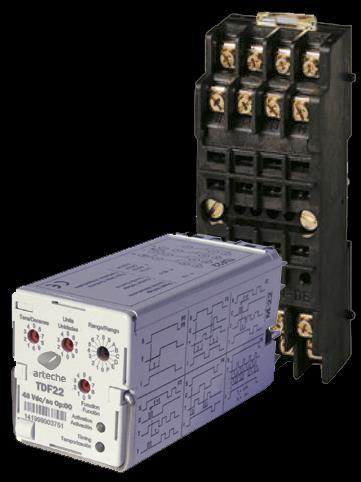
10 FUNCTIONAL CHARACTERISTICS In a CTJ-8: The terminals d-a are for the auxiliary supply of the relay. If the command is dependent, the negative of the same will be shared with the negative of the auxiliary supply (terminal A) and the control signal will be B. In the case of independent command the terminals B-C will be the relay command signal or external control. The , , , , , , and are timer contacts. The 8-81, 7-71, 6-61, 5-51, 4-41, 3-31, 2-21 and 1-10 contacts are high breaking capacity contacts. * * Chapter 6. FUNCTIONAL CHARACTERISTICS 6.1. Timing To choose the desired timing, the relays have 3 selectors available on the front part: in each of them the position of the point of the arrow indicates the option number selected. All the selectors are of discreet step not continuous, and for this reason the arrow cannot stay in an intermediate position. Time-Lag Relays User s Handbook (General Model) 10
11 FUNCTIONAL CHARACTERISTICS The 16 position selector with the indication Range, on top right part, allows to choose between the different 16 time ranges available. Each of the ranges is determined by a low limit and a top limit, as well as, by a step, as it is shown in the following table. This same table is printed on the left side of the relay. Range Low limit Top limit Step Range Low limit Top limit Step 0 30ms 990ms 10ms 8 10s 990s 10s 1 30ms 2,97s 30ms 9 0,5min 49,5min 0,5min 2 0,1s 9,9s 100ms A 1min 99min 1min 3 0,2s 19,8s 200ms B 3min 297min 3min 4 0,5s 49,5s 0,5s C 5min 495min 5min 5 1s 99s 1s D 10min 990min 10min 6 3s 297s 3s E 0,5h 49,5h 0,5h 7 5s 495s 5s F 1h 99h 1h Time-Lag Relays User s Handbook (General Model) 11
12 FUNCTIONAL CHARACTERISTICS On the following example, the chosen range would be the 5, which low limit is 1 second and the top is 99 seconds, with a step of 1 second. The combination of the two 10 position selectors, placed on the left side of the Range selector, allows selecting a number between 1 and 99. The number selected on the selector Tens multiplied by 10, plus the number selected on the selector Unit will be the chosen number. Once the range is selected, this number is the times that the step is going be multiplied, in order to choose this way the time on which the relay will operate. This way, on the following example: The range that has been chosen is the 5, which step is 1 second. As the tens selector is on the position 5 (5*10=50) and the unit one is on the 3 (50+3=53), the relay will temporize 53 times the step, in other words, it will temporize 53 x 1 = 53 seconds. NOTE 1: If the tens selector is placed on the 0 and the unit one on the 0 or on the 1, the relay temporizes the step of the selected range. NOTE 2: As the relay cannot temporize less than 30 milliseconds, if by the selectors it is chosen an option that would suppose a timing lower than this value, the relay will temporize 30ms. (for example, if it is selected the range 0, tens 0, and units 1 or 2, according to what was mentioned on the preceding Time-Lag Relays User s Handbook (General Model) 12
13 FUNCTIONAL CHARACTERISTICS page, the timing would be 10 ms or 20 ms respectively, but the relay will temporize 30 ms as it is the minimum timing limit). On the rest of the positions the timing will be the selected value. NOTE 3: If all the selectors are placed on 0 (Tens 0, Units 0, Range 0 and Function 0), the timing will be disabled and the relay will operate in the minimum time possible (electronical and mechanical initialization delay). This time is a bit lower than 20ms. In a relay with an instantaneous coil, both coils the instantaneous and the time-lag will operate at the same time. NOTA 4: The accuracy of the timing will be ±5ms or ±1%, the one which is higher. In a TDF-4DO: With fix timing: The contacts will have a drop-off delay as indicated on the front part. With selectable timing. The contacts drop-off is selected with a potentiometer on the front part Functions Below the 3 timing selectors, there is a forth 10 position selector, which allows to choose the different functions that the relay can execute. The way to make the selection is the same as ones explained before, by the point of the arrow. On the figure shown below, the selected function would be the 6. Time-Lag Relays User s Handbook (General Model) 13
14 FUNCTIONAL CHARACTERISTICS The time diagrams for each of the functions available are printed on the right side of the relay. The descriptions, as well as, the mentioned diagrams for each of these functions are shown below. The following table resumes all the functions available with a short description of each one: Function 0 Function 1 Function 2 Function 3 Function 4 Function 5 Function 6 Function 7 Function 8 Function 9 Function TDF-4DO RBF Pick up timing Pick up timing with acceleration by external command Drop out timing, the instantaneous part of the TDF-22 follow the auxiliary supply Drop out timing, the instantaneous part of the TDF-22 follow the external control Timing with continuity control Permanent cycle timing Flashing timing Pick up timing Drop out timing Pick up timing with reduced reseting time Drop out timing Impulse relay Time-Lag Relays User s Handbook (General Model) 14
15 FUNCTIONAL CHARACTERISTICS FUNCTION 0 FUNCTION 9: Pick up timing. As soon as the relay is with auxiliary supply, the timing starts, and the contacts pick up (go from the resting position to the working position) after a period of time t has passed (selected time). In the TDF-2, TDF-4, CTF-2, CTF-4, TDJ-8 and CTJ-8, the four contacts operate this way. In the TDF-22 (that is the relay to which belongs the following time diagram), and TDJ-44, the timer contacts operate as it is indicated on the described function, while the two instantaneous contacts will stay picked up every time the relay has auxiliary supply (the contacts follow the auxiliary supply). The only difference between functions F0 and F9 is the time the relay resets, (becomes operative again), after a loss of auxiliary supply. In the function F0, as in the rest of the functions except F9, this time is guaranteed to be less than 200 milliseconds, being at the same time, higher than 100 milliseconds (because this 100 milliseconds is the voltage gap guaranteed). In the function F9, this time is 50 milliseconds. NOTE: The period of time mentioned above is the one the relay takes in reset itself (start working as if it has been connected with auxiliary supply for the first time). If the relay loses the auxiliary supply for a lower period of time, the contacts drop out (the mechanics detect the loss) but the timing goes on as if there has not been any loss (the electronics do not detect the loss). Time-Lag Relays User s Handbook (General Model) 15
16 FUNCTIONAL CHARACTERISTICS FUNCTION 1 Pick up timing with acceleration by external command. This function differs from the function F0, in that there is an external command, that when the signal appears, the contacts pick up (go from the resting position to the working position), regardless of the timing that has been selected. In other words, as soon as the relay is with auxiliary supply, if there is no command signal, the contacts pick up in the period of time selected t; whereas if the command signal appears (which must last more than 10 ms) the contacts pick up, without waiting for this selected period of time to go by (as it is shown in the time diagram). In the TDF-2, TDF-4, CTF-2, CTF-4, TDJ-8 and CTJ-8, all contacts operate this way. In the TDF-22 (that is the relay to which belongs the following time diagram), and TDJ-44 the timer contacts operate as it is indicated on the described function, while the two instantaneous contacts will stay picked up every time the relay has auxiliary supply (the contacts follow the auxiliary supply). Time-Lag Relays User s Handbook (General Model) 16
17 FUNCTIONAL CHARACTERISTICS FUNCTION 2 Drop out timing If the relay is with auxiliary supply and the command signal appears (must last more than 10 ms) the contacts pick up (go from the resting position to the working position); once the command signal disappears, the selected period of time starts to count, after which the contacts drop out (go from the working position to the resting position). In case the command signal disappears and appears again after a period of time t lower than the time t, the relay clock resets and goes to zero, restarting the time counting. Once the command signal disappears, the contacts continue to be in the working position until the selected period of time t has passed, moment in which the contacts drop out. In the TDF-2, TDF-4, CTF-2, CTF-4, TDJ-8 and CTJ-8, all contacts operate this way. In the TDF-22 (that is the relay to which belongs the following time diagram), and TDJ-44 the timer contacts operate as it is indicated on the described function, while the two instantaneous contacts will stay picked up every time the relay has auxiliary supply (the contacts follow the auxiliary supply). Time-Lag Relays User s Handbook (General Model) 17
18 FUNCTIONAL CHARACTERISTICS FUNCTION 3 Drop out timing. Identical to function 2 in the TDF-2, TDF-4, CTF-2, CTF-4, TDJ-8 and CTJ-8. In the TDF-22 and TDJ-44 the difference is that the instantaneous contacts stay picked up while the command signal exists (provided that the relay has auxiliary supply), in other words, the contacts follow the command, not the auxiliary supply as in the preceding function. Time-Lag Relays User s Handbook (General Model) 18
19 FUNCTIONAL CHARACTERISTICS FUNCTION 4 Timing with continuity control. When the relay has auxiliary supply, the time t (selected period of time) starts to count, after which the contacts pick up (go from the resting position to the working position). If there is no command signal, the contacts stay this way every time the relay has auxiliary supply. The moment the command signal appears (must last more than 10 ms) the contacts drop out (go from the working position to the resting position). Just after the command signal disappears, the period of time t starts to count, after which the contacts return to the working position. The resting position will be recovered as soon as the command signal appears again. In the TDF-2, TDF-4, CTF-2, CTF-4, TDJ-8 and CTJ-8, all contacts operate this way. In the TDF-22 (that is the relay to which belongs the following time diagram), and TDJ-44 the timer contacts operate as it is indicated on the described function, while the two instantaneous contacts will stay picked up everytime the relay has auxiliary supply (the contacts follow the auxiliary supply). Time-Lag Relays User s Handbook (General Model) 19
20 FUNCTIONAL CHARACTERISTICS FUNCTION 5 Permanent cycle timing As soon as the relay has auxiliary supply a timing cycle begins, in which the contacts are 12 hours dropped out and 2 seconds picked up. This process lasts while the relay has auxiliary supply. In the TDF-2, TDF-4, CTF-2, CTF-4, TDJ-8 and CTJ-8, all contacts operate this way. In the TDF-22 (that is the relay to which belongs the following time diagram), and TDJ-44 the timer contacts operate as it is indicated on the described function, while the two instantaneous contacts will stay picked up every time the relay has auxiliary supply (the contacts follow the auxiliary supply). Time-Lag Relays User s Handbook (General Model) 20
21 FUNCTIONAL CHARACTERISTICS FUNCTION 6 Flashing timing As soon as the relay has auxiliary supply the timing begins, and after the selected period of time T the contacts pick up (go from the resting position to the working position) and remain in that position for the same period of time. After this time, the contacts drop out (go from the working position to the resting position) and remain in this position for the time T and so on, until the auxiliary supply disappears. This process changes in case the command signal appears (it must last longer than 10 ms). If this happens, while the command signal exists the contacts remain picked up. Once this signal disappears, the contacts stay in the working position for the period of time T, and afterwards start again with the timing cycles as explained above. In the TDF-2, TDF-4, CTF-2, CTF-4, TDJ-8 and CTJ-8, all contacts operate this way. In the TDF-22 (that is the relay to which belongs the following time diagram) and TDJ-44 the timer contacts operate as it is indicated on the described function, while the two instantaneous contacts remain picked up while the command signal exists (provided that the relay has auxiliary supply), in other words, the contacts follow the command. Time-Lag Relays User s Handbook (General Model) 21
22 FUNCTIONAL CHARACTERISTICS FUNCTION 7 Pick up timing. If the relay is with auxiliary supply and the command signal appears (must last longer than 10 ms), the contacts pick up (go from the resting position to the working position) and remain in that position for a period of time t. The time starts running once the command signal appears. If it disappears and returns again before it has passed the time t, does not affect to the counting. The time starts to count when the command appears, and only the first time for each timing. It can happens that the time t of the command signal could be longer than the timing t, the contacts pick up when the command signals begins to temporize the time t. Once the time t is over, the command signal remains and the selected period of time starts to count, after which the contacts drop out, regardless of the fact that the command signal disappeared in the mean time In the TDF-2, TDF-4, CTF-2, CTF-4, TDJ-8 and CTJ-8, all contacts operate this way. In the TDF-22 (that is the relay to which belongs the following time diagram), and TDJ-44 timer contacts operate as it is indicated on the described function, while the instantaneous contacts remain picked up while the command signal exists (provided that the relay has auxiliary supply), in other words, the contacts follow the command. Time-Lag Relays User s Handbook (General Model) 22
23 FUNCTIONAL CHARACTERISTICS FUNCTION 8 Drop out timing. If the relay is with auxiliary supply and the command signal appears and disappears (must last longer than 10 ms), the contacts pick up (go from the resting position to the working position) and remain in that position for a period of time t. The time starts running once the command signal disappears. If it returns and goes away before it has passed the time t, does not affect to the counting. The time starts to count from the disappearance of the command and only the first time for each timing. In the TDF-2, TDF-4, CTF-2, CTF-4, TDJ-8 and CTJ-8, all contacts operate this way. In the TDF-22 (that is the relay to which belongs the following time diagram) and TDJ-44 the timer contacts operate as it is indicated on the described function, while the instantaneous contacts remain picked up while the command signal exists (provided that the relay has auxiliary supply), in other words, the contacts follow the command. Time-Lag Relays User s Handbook (General Model) 23
24 FUNCTIONAL CHARACTERISTICS FUNCTION TDF-4DO Drop-off time lag. When the relay is energized and the contacts are in working position, as the auxiliary voltage supply disappears the contacts go back to their original position after a period of time t. FUNCTION RBF The RBF-2 and RBF-4 have an impulse relay function. With the power supply on, every impulse in the trigger input changes the contact position. Time-Lag Relays User s Handbook (General Model) 24
25 FUNCTIONAL CHARACTERISTICS 6.3. Indicators in the relay There are 2 led on the front part of the relay (See figure in page 4): Activation Led: it is a green led that is illuminated permanently when the timer contacts are picked up. Timing Led: it is a red led that flashes intermittently while the timing is in process in the relay, and turns off once the timing has finished. In a TDF-4DO: Activation Led: it is a green led that is illuminated permanently when the timer contacts are picked up Changing the time or function settings In case the time or function selectors are changed, two situations may happen: The changes are made in the relay without the auxiliary supply: in this case, the changes in the settings, both in the timing and in the the function, will we applied the next time the relay has auxiliary supply. The changes are made while the relay has auxiliary supply: in this case, the modifications will not applied until the relay completely loses the auxiliary supply and is restored again. The loss of the auxiliary supply must be longer than 1s. In other words, it is necessary to disconnect the auxiliary supply of the relay at least 1 second to make effective any change of time or timing function. Time-Lag Relays User s Handbook (General Model) 25
26 TECHNICAL CHARACTERISTICS Chapter 7. TECHNICAL CHARACTERISTICS Standard voltages (UN): 24,48,72,96,110,125,220 Vdc/Vac: 50/60 Hz (Vdc/Vac voltage supply available in the same relay) TDF-4DO: 24, 48, 72, 96, 110 Vcc Voltage operation range: +25% -30% U N (except 220 Un and TDF-4DO: +10% -20%) Consumption (U N): TDF-2, RBF-2,CTF-2 3,16 W TDF-22: TDF-4, TDF-4DO, RBF-4, CTF-4: TDJ-44: TDJ-8, CTJ8: 6,00 W 4,52 W 8,81 W 6,89 W Contacts: Permanent current: 10 A Instantaneous current: 30 A/1 s;80 A/200 ms; 150 A/10 ms Making capacity: 40 A/0,5 s/110 Vdc Breaking capacity for 105 operations: 1,2 A; 110 Vdc; 0 ms 0,8 A; 110 Vdc; 20 ms 0,5 A; 220 Vdc; 0 ms 0,3 A; 220 Vdc; 20 ms Time-Lag Relays User s Handbook (General Model) 26

27 STADARDS AND TESTS High breaking capacity range (CTF-2, CTF-4, CTJ8): U max, opened contact: 250 Vdc/400 Vac Mechanical life: 10 7 operations Operating temperature: -10 C +55 C Operating humidity: 93%/40 C Seismic characteristics according to IEEE501 Degree of ZPA: 3 g/33 Hz Chapter 8. STADARDS AND TESTS 8.1. Construction Standards Electrical test IEC Dielectric test 2 kv/50 Hz/1 min Surge withstand 5 kv/1,2/50 µs Insulation Inflammability tests Plastic materials > 2000 MΩ/500 Vdc IEC UL94: V0 IEC 60695: 850 C/30 s Cover protection degree IEC60529, EN60529: IP40 Time-Lag Relays User s Handbook (General Model) 27
28 STADARDS AND TESTS Climatic tests Dry heat Non-dissipating sample Dissipating sample Cyclic humid heat Cold 100 cycles Non-dissipating sample Thermal aging test At nominal voltage (U N ) IEC IEC C/96 h +55 C/96 h IEC : +55 C/12 h IEC C/2h IEC ºC/1440 h 8.2. Electromagnetical Compatibility Tests Electrostatic discharge (level 3) Air mode Contact mode Radiated electromagnetic field (level 3) EN , IEC ± 8 kv ± 6 kv EN , IEC V/m Fast transient (burst) (level 4) Aux. supply Inputs Impulse test voltage (surge) (level 3) Common mode Differential mode Conducted disturbances induced by radio frequency fields (level 5) Power frequency magnetic field (level 5) Permanent EN , IEC ±4 kv/5 khz ±4 kv/5 khz EN , IEC ±2 kv ±1 kv EN , IEC V EN , IEC A/m Time-Lag Relays User s Handbook (General Model) 28
29 STADARDS AND TESTS During 1s Damped oscillatory magnetic field 1000 A/m EN , IEC MHz and 0,1 MHz (level 5) 100 A/m Oscillatory waves 1 MHz and 0,1 MHz (level 3) EN A/m Common mode Differential mode 2,5 kv 1 kv 8.3. Vibration and shock stress tests Railway applications. Rolling stock equipment. IEC Vibration and shock test: Test Level Category 1, Class B Requirements for vibration and shock testing RIA 20 of equipment intended for use on railway vehicles: Test Level Category 1, Class B Recommended Practice for Seismic Qualification of Class 1E Equipment for Nuclear Power Generating Stations IEEE 344 Test Level: ZPA = 3 with sockets mounted on Rail DIN ZPA = 3,5 with screwed socket Time-Lag Relays User s Handbook (General Model) 29


30 DIMENSIONS AND TYPES OF SOCKETS Chapter 9. Dimensions and types of sockets 9.1. Dimensions of the relays TDF-22, TDF-4, CTF-2, CTF-4, RBF and TDF-4DO 9.2. Dimensions of the relays TDJ-44, TDJ-8 and CTJ-8. Time-Lag Relays User s Handbook (General Model) 30
31 DIMENSIONS AND TYPES OF SOCKETS 9.3. Sockets. TDF-2, TDF-22, TDF-4, CTF-2, CTF-4, TDF-4DO, RBF TDJ-44, TDJ-8, CTJ-8 Screw Doble Faston Screw Doble Faston Front connection FN-DE IP 10 FN-DE2C IP 10 JN-DE IP 10 JN-DE2C IP 10 Rear connection F-TR OP FN-TR2C OP JN-TR OP JN-TR2C OP Flush mounting F-EMP OP J-EMP OP Time-Lag Relays User s Handbook (General Model) 31
32 MODEL SELECTION TABLE TDF/TDJ Appendix A. Model selection table TDF/TDJ RANGE AND SELECTION TABLE Model Contacts type Voltage Vcc Vca OP 0 X 0 TDF-2 2 timer contacts TDF-4 4 timer contacts TDF timer + 2 instantaneous TDJ-8 8 timer contacts TDJ-44 4 timer + 4 instantaneous OPTIONS Dependent 0 24 Vdc Vac 1 48 Vdc Vac 2 60 Vdc Vac 3 Independent command voltage 72 Vdc Vac 4 96 Vdc Vac Vdc Vac Vdc Vac Vdc Vac 8 Example: TDF-22, 125 Vcc OP000 Time-Lag Relays User s Handbook (General Model) 32

33 MODEL SELECTION TABLE TDF-4DO Appendix B. Model selection table TDF-4DO Example: TDF-4DOF 890M 110Vdc FF, TDF-4DO 1000M 96 Vdc FF Time-Lag Relays User s Handbook (General Model) 33

34 MODEL SELECTION TABLE TIME LAG CONTACTORS Appendix C. Model selection table Time Lag Contactors * Energy / Railway application. Example: CTF-2 110Vdc/Vac OP2 FF Time-Lag Relays User s Handbook (General Model) 34

35 MODEL SELECTION TABLE RBF Appendix D. Model selection table RBF Example: RBF Vdc FF Time-Lag Relays User s Handbook (General Model) 35

36 _MU_RELES-TDF-TDJ_EN_2012_V38 Arteche
02/11/2015
 DIN Rail Mount 17.5 mm MUS/MUSF 80 AC/DC Part number 84872141 Control relays monitoring their own power supply - MUS : Over/undervoltage control Selectable latching (memory) function - MUSF : Over/undervoltage
Series CT7N Bimetallic Overload Relays
 Series CT7N imetallic Overload Relays Choose CT7N overloads in DC applications and when monitoring Variable Frequency Drives Sprecher + Schuh has always paid particular attention to the subject of motor
15 Series - Dimmer
 Features Master slave system for multiple load dimming Suitable for incandescent and halogen lighting loads (with or without transformer or electronic supply) Compatible with energy saving (CF or ED) dimmable
Dimmers SЕRIES. Kitchen light control. Bedroom light control. Living room light control
 Kitchen light control Bedroom light control 15 SЕRES iving room light control ighting control in corridors (for hotels, offices and hospitals) FDER reserves the right to alter characteristics at any time
MULTIS L72. Operating instructions
 GB MULTIS L72 Operating instructions 2 SOCOMEC - Ref. : 876 091B ENGLISH GB Contents PRELIMINARY OPERATIONS 4 GENERAL INFORMATION 5 PRESENTATION 4 INSTALLATION 5 Mechanical environment Climatic environment
Multifunction Digital Timer
 Multifunction Digital Timer 72 x72 mm Timer with Easy-to-use Functions Nine output modes accommodate a wide variety of applications. All parameters set by scroll-through menus accessed from the front panel.
Weekly Time Switch. Rated time Time setting range Time division 24 hrs x 7 days 00:00 to 23:59 1min
 Weekly Time Switch Easy Programming with Large LCD Display and Interactive Functions Programming for 24 hrs x 7 days using just five switches. Sixteen program steps available. Power supply freely selectable
Advantys STB DATA SHEET. Advantys STB Output Module. Description. Features
 Advantys STB Advantys STB Output Module DATA SHEET Description The Advantys model STBDAO5260 Digital Output Module provides 2 isolated discrete output points that operate on a 115 VAC power source. The
Weekly Timer. Mounting track 50 cm (1.64 ft) length PFP-50N 1 m (3.28 ft) length PFP-100N
 length PFP-50N 1 m (3.28 ft) length PFP-100N") Weekly Timer 1/4 DIN Size Timer Features Prompted Programming and Large LCD Display 24 hours x 7 days programming using just 5 switches 16 program steps and cycle operation Two independent 15 A control
Weekly Timer 1/4 DIN Size Timer Features Prompted Programming and Large LCD Display 24 hours x 7 days programming using just 5 switches 16 program steps and cycle operation Two independent 15 A control
LONWORKS Fibre Optic Converter
 LONWORKS Fiber Optic Converter LRW-102 and LRW-102/PP LONWORKS to fibre optic link, multidrop and redundant ring applications The LRW-102 is a fibre optic modem designed for multidrop and redundant ring
AS09..S 3-pole Contactors - Spring Terminals
 4 kw 5 hp AS09..S 3-pole Contactors - Spring AC Operated Description - 3-pole contactors with spring terminals, - N.C. or N.O. built-in auxiliary contact, - Rail-mounted, no tools required, - Additional
Type MG-6 Auxiliary Relay Class 1E
 Type MG-6 Auxiliary Relay Class 1E Product Guide Device Number: 94X, Y, Z ZPA Rating 4.2g ABB Application MG-6 relays have been specially designed and tested to establish their suitability for Class 1E
DATA SHEET. The Advantys model STBDAI5260 Digital Input Module provides 2 isolated discrete input points that operate on a 115 VAC power source.
 Advantys STB Advantys STB Input Module DATA SHEET Description The Advantys model STBDAI5260 Digital Input Module provides 2 isolated discrete input points that operate on a 115 VAC power source. Features
LONWORKS Fibre Optic Router
 LONWORKS Fiber Optic Router LRW-112 and LRW-112/PP LONWORKS to fibre optic link, multidrop and redundant ring applications The LRW-112 router offers an easy way to extend the distance between LONWORKS
Magnecraft Power Relays
 Description DPST-NO, 30 A; DPDT, 30 A (NO) / 3 A (NC) Description The series power relays offer a small package size and features Class F insulation for a maximum coil temperature of 55 C (3 F). These
Instruction Manual. Universal Flow Controller Model 261 / 261-EC-01
 Universal Flow Controller Model 261 / 261-EC-01 Instruction Manual Type ARS 261-EC 01 Art.-no: 82212264 Table of Contents 1. Safety Instructions 2. Product ID - Dimensions 3. Function Description 4. Installation
PBC series. RoHS. Ready. IEC-Type Contactors & Accessories 9-80 Amp AC-3, Amp AC-1 AC Coils. P&B PBC Series IEC Type Contactors & Accessories
 PBC series IEC-Type Contactors & Accessories 9-80 Amp AC-3, 25-125 Amp AC-1 AC Coils File E38802 (PBC) RoHS Ready Users should thoroughly review the technical data before selecting a product part number.
PRINCIPLES AND APPLICATIONS
 GENERATION & NETWORK Digital Automation Measuring and Control Devices AMS7000 PROCOM The optimum operation of an electrical network depends particularly on the reliability and the availability of the protection,
Generator protection relay
 Page 1 Issued: April 1999 Status: New Data subject to change without notice Features Off-the-shelf generator protection relay for small and medium sized power generators Three-phase time overcurrent and
Rack mounted telephone- and leased line modem for industrial applications
 Rack mounted telephone- and leased line modem for industrial applications TR-6 Rack modem for industrial PSTNand /-wire leased line applications The TR-6 is an analogue V. 9 -rack PSTN modem as well as
Datasheet - SRB301LC 24VAC/DC
 25.02.2016-18:05:23h Datasheet - SRB301LC 24VAC/DC Guard door monitors and Safety control modules for Emergency Stop applications / General Purpose safety controllers (Series PROTECT SRB) / SRB301LC Preferred
Ordering details. Approval. Classification
 Datasheet - SRB 301MC-24V Guard door monitors and Safety control modules for Emergency Stop applications / General Purpose safety controllers (Series PROTECT SRB) / SRB 301MC Fit for signal evaluation
ODW-621. RS-232 Point-to-point applications
 Re-timing Data rate up to 250 kbit/s 9-position D-sub connector Redundant power supply inputs Status interface for fault indication Fibre link fault indication (Red) Design for harsh environments 40 to
SH2RE16A4. Output relay module. Benefits. Description
 Output relay module Benefits Integrated system. Dupline is the brand name for Carlo Gavazzi s 2-wire bus system. Cost reduction. The use of a bus system is a proven way to reduce installation costs - especially
Fibre optic router for TP/FT-10 LRW-112PP
 Fibre optic router for TP/FT-10 LRW-112PP Lo n Wo r k s to fibre optic link, point-to-point applications The LRW-112PP router offers an easy way to extend the distance between LONWORKS 78 kbit/s TP/FT
Fiber-Optic Sensor Amplifiers E3S-X3, E3X-NL and E3X-NM Discontinued March 2012; Revised Replacements
 NO: PH-165 PRODUCT: E3S-X3, E3X-NL, E3X-NM DATE: August 2012 TYPE: Discontinuation Update Fiber-Optic Sensor Amplifiers E3S-X3, E3X-NL and E3X-NM Discontinued March 2012; Revised Replacements Affected
Solid-State Digital Timer
 Solid-State Digital Timer 1/16 DIN, Digital-Set Timer with 0.1 Second to 9,990 Hours Range 8 field-selectable operation modes Universal AC/DC supply voltage timers available Operations include ON-delay,
2 2 Relay outputs. M DIN W72 H7mm. LE7 Weekly/Yearly timer
 LE7M-2 W72 H72mm, Weekly/Yearly Timer Features Easy to check and change the program setting Customizable weekly or yearly unit time setting and control by user Includes daylight saving time function Built-in
TeSys contactors. Model d. Type of contactor LC1- LC1- LC1- LC1- LC1-D115 & D09 D18 D25 D38 D40 D50 D95 LC1-D150 DT20 & DT25 DT32 & DT40
 Characteristics Type of contactor LC- LC- LC- LC- LC-D & D09 D8 D2 D38 D40 D0 D9 LC-D0 DT20 & DT2 DT32 & DT40 Environment Rated insulation voltage (Ui) Conforming to IEC 947-4-, overvoltage category III,
ALLEN BRADLEY TIMING RELAY
 ALLEN BRADLEY TIMING RELAY Configuration Details Product: 700-HS12BA1 Description: 700-HS General Purpose Square Base Timing Relay, On Delay Timer, 1.0 to 180 seconds, DPDT, 120V AC 50/60Hz CONTROL RELAY
Fibre Optic Modem ODW-611
 Fibre Optic Modem ODW-611 PROFIBUS DP to fibre optic link, point-to-point applications The ODW-611 is a fibre optic modem designed for point-to-point fibre optic connections between PROFI- BUS DP networks.
I r A Protection against direct contact Finger and back of hand proof to VDE 0106 Part 100
 DATASHEET - NZMH2-A100 Circuit-breaker, 3p, 100A Part no. NZMH2-A100 Catalog No. 259099 Similar to illustration Delivery program Product range Circuit-breaker Protective function System and cable protection
Protective function Systems, cable, selectivity and generator protection. i 2 t constant function: switchable. I r A
 DATASHEET - NZMN3-VE630 Circuit-breaker, 3p, 630A Part no. NZMN3-VE630 Catalog No. 259133 EL-Nummer (Norway) 0004358791 Similar to illustration Delivery program Product range Circuit-breaker Protective
Magnecraft General Purpose Relays 750R Series DPDT and 3DPT, 10 A
 and 3DPT, 10 A UL Listed when used with proper Magnecraft s The 750R series octal base, plug-in relays offer clear or full-feature covers with multiple mounting options and accessories. 750R 750R Full-Feature
Fibre Optic Modem ODW-622
 Fibre Optic Modem ODW-622 RS-232 to fibre optic link, redundant ring or multidrop applications The ODW-622 can be used to create either redundant ring or multidrop solutions for devices with RS-232 interfaces.
I/A Series Hardware Fiber Optic LAN Converter
 I/A Series Hardware PSS 21H-7F3 B4 The provides bidirectional conversion between coaxial and fiber optic media. The converter is compatible with existing I/A Series system hardware, utilizes industry standard
I r A Protection against direct contact Finger and back of hand proof to VDE 0106 Part 100
 DATASHEET - NZMC1-A160 Circuit-breaker, 3p, 160A Part no. NZMC1-A160 Catalog No. 283296 Similar to illustration Delivery program Product range Circuit-breaker Protective function System and cable protection
A V 50Hz / V 60Hz
 A16-22-00 400-415V 50Hz / 415-440V 60Hz Products Low Voltage Products and Systems Control Products Contactors Block Contactors General Information Extended Product Type: A16-22-00 400-415V 50Hz / 415-440V
with handle LIMOGES Cedex 1. DESCRIPTION - USE 3. DIMENSIONS Symbol: Technology: Use:. For controlling a load remotely via a switch 2.
 87045 LIMOGES Cedex Téléphone : 05 55 06 87 87 Télécopie : 05 55 06 88 88 25A power contactors silent CONTENTS PAGES 1. Description, use... 1 2. Range... 1 3. Dimensions... 1 4. Positioning - Connection...
Assembly. Front view. LEDs. Parametrization interface. Power Bus
 otation Speed Monitor Features Assembly 1-channel signal conditioner 2 V DC supply Input for 2- or -wire sensors Input frequency 10 mhz... 50 khz elay contact output Start-up override and restart inhibit
SEL-3405 High-Accuracy IRIG-B Fiber-Optic Transceiver
 SEL-3405 High-Accuracy IRIG-B Fiber-Optic Transceiver Accurate IRIG-B Over Fiber Optics Major Features and Benefits The SEL-3405 High-Accuracy IRIG-B Fiber-Optic Transceiver can send high-accuracy demodulated
Description Set value in neutral conductor is synchronous with set value Ir of main pole. R.m.s. value measurement and thermal memory CSA 100
 DATASHEET - NZMN3-4-AE400 Circuit-breaker, 4p, 400A Part no. NZMN3-4-AE400 Catalog No. 265891 Similar to illustration EL-Nummer (Norway) 0004358857 Delivery program Product range Circuit-breaker Protective
ORDERING Page 6 STANDARDS, DIMENSIONS and ACCESSORIES Request bulletin SDA
 BE1-59NC CAPACITOR NEUTRAL OVERVOLTAGE RELAY The BE1-59NC Capacitor Neutral Overvoltage Relay provides sensitive protection for capacitor banks. ADVANTAGES Helps avoid cascading capacitor failures. Sensing
ORDERING Page 6 BASLER RELAY STANDARDS, DIMENSIONS, ACCESSORIES Request bulletin SDA
 BE1-59NC CAPACITOR NEUTRAL OVERVOLTAGE RELAY The BE1-59NC Capacitor Neutral Overvoltage Relay provides sensitive protection for capacitor banks. ADDITIONAL INFORMATION INSTRUCTION MANUAL ADVANTAGES Helps
Type Contact form Model PCB SPDT G6E-134P-ST-US G6E-134PL-ST-US. Type Contact form Model
 Low Signal Relay G6E Subminiature 7.87 H x.1 W x 16 L mm (0.31 H x 0.3 W x 0.63 L in). High sensitivity with pick-up coil power of 8 mw. Surge withstand meets FCC Part 68 rule and Telcordia 2.5 kv Specifications.
CT7N CT7 CT7K 4 6 CT TJ 4 6 CT7K TKK 6 10 CT TK 6 9 CT7K TKL
 Obsolete Overload Cross Reference Series CT7/CT7K to Cross Reference CT7 CT7K Directly Mounts to Contactor... Adjustment Catalog Adjustment Catalog Adjustment Catalog Code Code Range (A) Number Range (A)
LC1D12P7 TeSys D contactor - 3P(3 NO) - AC-3 - <= 440 V 12 A V AC coil
 - AC-3 - <= 440 V 12 A V AC coil") Characteristics TeSys D contactor - 3P(3 NO) - AC-3 -
Characteristics TeSys D contactor - 3P(3 NO) - AC-3 -
DLP200M 2 Relay Module for Heating and Cooling Plants
 Product Sheet TH6.24 Thermostat Type DLP200M DLP200M 2 Relay Module for Heating and Cooling Plants The DLP 200 M is a relay module for activation of loads (namely thermal actuators or circulators) in wireless
Type: DILM12 10(24VDC) Article No.:
 Article No.:") Type: DILM12 10(24VDC) Article No.: 276845 Ordering information Rated operational current AC 3 400 V I e A 12 Max. rating for three phase motors, 50 60 Hz AC 3 230 V Max. rating for three phase motors,
Type: DILM12 10(24VDC) Article No.: 276845 Ordering information Rated operational current AC 3 400 V I e A 12 Max. rating for three phase motors, 50 60 Hz AC 3 230 V Max. rating for three phase motors,
User Manual CC DC 24 V 5A. Universal Control Unit UC-1-E. General Information SET. Universal Control Unit UC-1 Of Central Lubrication PAUSE CONTACT
 Universal Control Unit UC-1-E User Manual General Information Universal Control Unit UC-1 Of Central Lubrication CC DC 24 V 5A / M 15 SL /MK 31 M Z 30 General Information Contents Universal Control Unit
Description Set value in neutral conductor is synchronous with set value Ir of main pole. CSA 100. conductor. I r A 50-63
 Circuit-breaker,4p,63A Partno. NZMH1-4-A63 Articleno. 284426 Similar to illustration Deliveryprogram Product range Circuit-breaker Protective function System and cable protection Standard/Approval IEC
3M Sensored Termination (15 kv) QX-T15I-vi1-E
 QX-T15I-vi1-E") 3M Sensored Termination () QX-T15I-vi1-E Data Sheet May 2016 Kit Contents: Each kit contains sufficient quantities of the following materials to make three single-phase terminations. 31" (REF) One piece
3M Sensored Termination () QX-T15I-vi1-E Data Sheet May 2016 Kit Contents: Each kit contains sufficient quantities of the following materials to make three single-phase terminations. 31" (REF) One piece
 SINCE 1989 Quality Products, Prompt Services, Trustful Relationships www.kmindustrialcorp.com KM Industrial Corporation has established itself as a trusted supplier of Electrical, Machinery and Industry
Climatic proofing Damp heat, constant, to IEC Damp heat, cyclic, to IEC
 Deliveryprogramme Contactorrelay,3N/O+1N/C,AC Partno. DILER-31(230V50HZ,240V60HZ) Articleno. 051768 CatalogNo. XTRM10A31F Product range DILER Mini-contactors Application Contactor relays Description with
LC2D09E7 REVERSING CONTACTOR 575VAC 9A IEC
 Product datasheet Characteristics LC2D09E7 REVERSING CONTACTOR 575VAC 9A IEC Price* : 86.25 GBP Main Range Product name Product or component type Device short name Contactor application Utilisation category
Datasheet - SRB-E-201ST
 27.04.2016-16:36:21h Datasheet - SRB-E-201ST Multi-function safety modules / SRB-E-201ST STOP 0 Function 1 oder 2-channel control Start button / Auto-start Monitoring two-hand control panels to EN 574
LC1D12B7 TeSys D contactor - 3P(3 NO) - AC-3 - <= 440 V 12 A - 24 V AC coil
 - AC-3 - <= 440 V 12 A - 24 V AC coil") Characteristics TeSys D contactor - 3P(3 NO) - AC-3 -
Characteristics TeSys D contactor - 3P(3 NO) - AC-3 -
Type Contact form Model
 Low Signal Relay G6A High sensitivity can be driven by digital circuits. Low-profile design allows use in.70 mm (0.50 in) PC board rack. Surge withstand meets FCC Part 68 regulation. Units can be mounted
I r A Protection against direct contact Finger and back-of-hand proof to VDE 0106 part 100
 Circuit-breaker,3p,400A Partno. LZMC3-A400-I Articleno. 111955 Similar to illustration Deliveryprogramme Product range Circuit-breaker Protective function System and cable protection Standard/Approval
MULTIS LMp / LMg. Systèmes de Coupure et de Protection Switching and Protection Systems
 I MULTIS LMp / LMg F Notice d utilisation GB Operating instructions D Bedienungsanleitung NL Gebruiksaanwijzing Istruzioni per l uso SP Instrucciones de servicio P Manual de instruções Systèmes de Coupure
LC1D32P7 TeSys D contactor - 3P(3 NO) - AC-3 - <= 440 V 32 A V AC 50/60 Hz coil
 - AC-3 - <= 440 V 32 A V AC 50/60 Hz coil") Characteristics TeSys D contactor - 3P(3 NO) - AC-3 -
Characteristics TeSys D contactor - 3P(3 NO) - AC-3 -
Magnecraft General Purpose Relays 782 Power Series SPDT 20 A; DPDT 15 A
 72 Power Series SPDT 20 A; DPDT 15 A UL listed when used with proper Magnecraft sockets The 72 Plug-in Power relays offer clear or full-feature covers with multiple mounting options and accessories. Feature
Type: DILM25 10(24V50HZ) Article No.:
 Article No.:") Type: DILM25 10(24V50HZ) Article No.: 277119 Ordering information Rated operational current AC 3 400 V I e A 25 Max. rating for three phase motors, 50 60 Hz AC 3 230 V Max. rating for three phase motors,
Type: DILM25 10(24V50HZ) Article No.: 277119 Ordering information Rated operational current AC 3 400 V I e A 25 Max. rating for three phase motors, 50 60 Hz AC 3 230 V Max. rating for three phase motors,
Bulletin 190 IEC Modular Starter System
 Bulletin 90 Table of Contents Selection Guide Description Page Bulletin 90....................................... Accessories....................................... 7 Specifications.....................................
K-BUS Dimmer Module User manual-ver. 1
 K-BUS Dimmer Module User manual-ver. 1 KA/D0103.1 KA/D0203.1 KA/D0403.1 Content 1. Introduction... 3 2. Technical Parameter... 3 3. Dimension and Connection Diagram... 4 3.1 KA/D0103.1... 4 3.2 KA/D0203.1...
Single output models feature wide-range output adjustability to meet a wide variety of standard and user-specific output voltage requirements.
 RoHS Lead-Solder-Exemption Compliant New 3.3 V and 5 V Output Models Universal Input 85-264 VAC Industry-Standard Footprint: 7.0" x 4.3" x 1.97" (177.8 x 109.2 x 50.0 mm) Input Transient & ESD Compliance
Slot-type Photomicrosensor with connector or pre-wired models (Non-modulated) *1. configuration. Dark-ON/Light-ON
 *1. configuration. Dark-ON/Light-ON") Slot-type Photomicrosensor with connector or pre-wired models (Non-modulated) * EE-SX/6 Photomicrosensor with 0- to 00-mA direct switching capacity for built-in application. Series includes models that
Slot-type Photomicrosensor with connector or pre-wired models (Non-modulated) * EE-SX/6 Photomicrosensor with 0- to 00-mA direct switching capacity for built-in application. Series includes models that
Instructions for Use P.154-UP (9/4) P.155-UP (9/8) P.150-UP-12 (9/12) P.150-UP-16 (9/16)
 P.155-UP (9/8) P.150-UP-12 (9/12) P.150-UP-16 (9/16)") Satellite multiswitch Instructions for Use P.154-UP (9/4) P.155-UP (9/8) P.150-UP-12 (9/12) P.150-UP-16 (9/16) EMP-CENTAURI is a registered trademark Dear Customer, Thank you for buying the EMP-Centauri
Satellite multiswitch Instructions for Use P.154-UP (9/4) P.155-UP (9/8) P.150-UP-12 (9/12) P.150-UP-16 (9/16) EMP-CENTAURI is a registered trademark Dear Customer, Thank you for buying the EMP-Centauri
DLP600M 6+1 Relay Module for Heating and Cooling Plants
 Product Sheet TH6.25 Thermostat Type DLP600M DLP600M 6+1 Relay Module for Heating and Cooling Plants The DLP 600 M is a relay module for activation of loads (namely thermal actuators or circulators) in
Soft starter, 66 A, V AC, Us= 24 V DC, with control unit, Frame size N. Function Soft starter for three-phase loads, with control unit
 DATASHEET - S811+N66N3S Delivery program Soft starter, 66 A, 200-600 V AC, Us= 24 V DC, with control unit, Frame size N Part no. S811+N66N3S Catalog No. 168978 Eaton Catalog No. S811PLUSN66N3S EL-Nummer
2 2 Relay outputs. M DIN W72 H7mm. LE7 Weekly/Yearly timer
 Weekly/Yearly Timer W72 H72mm, Weekly/Yearly timer Features Easy to check and change the program setting Customizable weekly or yearly unit time setting and control by user Includes daylight saving time
Modular pulse operated latching relay 16 A
 87045 LIMOGES Cedex Telephone number: +33 (0)5 55 06 87 87 Fax: +33 (0)5 55 06 88 88 Modular pulse operated latc / 05 / 07 / 08 / 10 / 11 / 12 / 14 / 16 / 20 and 927 00 / 49 CONTENTS PAGES 1. Description,
Installation and User Guide 458/CTR8 8-Channel Ballast Controller Module
 Installation and User Guide 458/CTR8 8-Channel Ballast Controller Module Helvar Data is subject to change without notice. www.helvar.com i Contents Section Page Introduction 1 Installation 2 1. Attach
Standard RS232 RS ma
 1 / 5 CONTROL AND VISUALIZATION OF AC CURRENT IN SINGLE PHASE LINES BY EXTERNAL SHUNT Function Operating mode Current control Frequency control DC component control Shunt Timer Resolution Current precision
LC1D25G7 TeSys D contactor - 3P(3 NO) - AC-3 - <= 440 V 25 A V AC coil
 - AC-3 - <= 440 V 25 A V AC coil") Product data sheet Characteristics LC1D25G7 TeSys D contactor - 3P(3 NO) - AC-3 -
Product data sheet Characteristics LC1D25G7 TeSys D contactor - 3P(3 NO) - AC-3 -
LC1D09B7 TeSys D contactor - 3P(3 NO) - AC-3 - <= 440 V 9 A - 24 V AC coil
 - AC-3 - <= 440 V 9 A - 24 V AC coil") Product data sheet Characteristics LC1D09B7 TeSys D contactor - 3P(3 NO) - AC-3 -
Product data sheet Characteristics LC1D09B7 TeSys D contactor - 3P(3 NO) - AC-3 -
MILLITARY SPECIFICATION SHEET
 INCH-POUND MILLITARY SPECIFICATION SHEET 10 November 2000 SUPERSEDING MIL-R-6106/14B 10 March 1989 RELAY, ELECTRIC, PERMANENT DRIVE, 50 AMP, SPDT (DB) DOUBLE MAKE DOUBLE BREAK AUXILIARY CONTACTS (5 AMP),
Sequential and Combination Timer TK-415 with RS-232 communication
 NOVATEK-ELECTRO LTD. Sequential and Combination Timer TK-415 with RS-232 communication OPERATION MANUAL WWW.NOVATEK-ELECTRO.COM/EN 2011 1. GENERAL PROVISIONS 1.1. BASIC FUNCTIONS - microprocessor controlled.
LW10-T600. P10 Led Wall Display
 P10 Led Wall Display PANEL Led Type 3in1 Panel Size (W*H*D) (mm) 960x960x160 Pixel Pitch 10mm Module Size (W*H) (mm) 320x160 Pixel Configuration SMD 3535 Product Weight (Kg/m2) 42 PCB Layer 2 layer Material
LC1D150G7 TeSys D contactor - 3P(3 NO) - AC-3 - <= 440 V 150 A V AC coil
 - AC-3 - <= 440 V 150 A V AC coil") Product data sheet Characteristics LC1D150G7 TeSys D contactor - 3P(3 NO) - AC-3 -
Product data sheet Characteristics LC1D150G7 TeSys D contactor - 3P(3 NO) - AC-3 -
REV 303 PROGRAMMABLE MULTIFUNCTIONAL TIMER. «NOVATEK-ELECTRO» Ltd Intelligent industrial electronics OPERATING MANUAL.
 Ltd Intelligent industrial electronics PROGRAMMABLE MULTIFUNCTIONAL TIMER REV 303 OPERATING MANUAL Before using the Unit, please, carefully read the Operating Manual. www.novatek-electro.com ~ 2 ~ ATTENTION!
Photoelectrics Through-beam Type PA18C.T..., DC
 Photoelectrics Through-beam Type, DC Miniature sensor range Range: 20 m (Axial), 16 m (Radial) Sensitivity adjustment by potentiometer Modulated, infrared light 850 nm Supply voltage: to 30 VDC Output:
Specifications. Reference Documentation. Performance Conditions
 The material in this section is organized into two main groupings: the specification tables and the supporting figures. The specification tables include: 1. PAL general and test signal specifications 2.
Type Contact form Model Ag (Au clad) Standard DPDT G6A-274P-ST-US Low-sensitivity DPDT G6A-274P-ST40-US
 Standard DPDT G6A-274P-ST-US Low-sensitivity DPDT G6A-274P-ST40-US") Low Signal Relay G6A Fullly Sealed Relay with High Impulse Withstand High sensitivity can be driven by digital circuits. Low-profile design allows use in 12.70 mm PC board rack. Surge withstand meets FCC
Low Signal Relay G6A Fullly Sealed Relay with High Impulse Withstand High sensitivity can be driven by digital circuits. Low-profile design allows use in 12.70 mm PC board rack. Surge withstand meets FCC
3.5. Control Relays and Timers. Contents. 9575H Series 3000 Type AA, AC and DC. General Purpose Relays Type AA
 .5 9575H Series 000 Relay Contents 9575H Series 000 Type AA, AC and DC Product Selection....................... Accessories............................ Technical Data and Specifications........... Dimensions............................
LC1D65AF7 TeSys D contactor - 3P(3 NO) - AC-3 - <= 440 V 65 A V AC 50/60 Hz coil
 - AC-3 - <= 440 V 65 A V AC 50/60 Hz coil") Characteristics TeSys D contactor - 3P(3 NO) - AC-3 -
Characteristics TeSys D contactor - 3P(3 NO) - AC-3 -
LC1D09F7 TeSys D contactor - 3P(3 NO) - AC-3 - <= 440 V 9 A V AC coil
 - AC-3 - <= 440 V 9 A V AC coil") Product data sheet Characteristics LC1D09F7 TeSys D contactor - 3P(3 NO) - AC-3 -
Product data sheet Characteristics LC1D09F7 TeSys D contactor - 3P(3 NO) - AC-3 -
Magnetic and Hydraulic-Magnetic Circuit Breaker
 Magnetic and Hydraulic-Magnetic Circuit Breaker 850-... Description Single, two, three and four pole magnetic and hydraulic-magnetic circuit breakers with trip-free-mechanism and toggle or rocker actuation.
Instructions for Use P.160-AP-8 (13/8) P.160-CP-8 (13/8) P.160-CP-12 (13/12) P.160-CP-16 (13/16)
 P.160-CP-8 (13/8) P.160-CP-12 (13/12) P.160-CP-16 (13/16)") Satellite multiswitch Instructions for Use P.160-AP-8 (13/8) P.160-CP-8 (13/8) P.160-AP-12 (13/12) P.160-CP-12 (13/12) P.160-AP-16 (13/16) P.160-CP-16 (13/16) EMP-CENTAURI is a registered trademark Dear
Satellite multiswitch Instructions for Use P.160-AP-8 (13/8) P.160-CP-8 (13/8) P.160-AP-12 (13/12) P.160-CP-12 (13/12) P.160-AP-16 (13/16) P.160-CP-16 (13/16) EMP-CENTAURI is a registered trademark Dear
User s Manual. LG Industrial Systems G3F AT4A. LG Programmable Logic Controller
 User s Manual LG Programmable Logic Controller G3F AT4A GLOFA G4F AT3A LG Industrial Systems CONTENTS Chapter 1. INTRODUCTION 1.1 Features 1-1 Chapter 2. SYSTEM CONFIGURATION 2.1 Example of System Configuration
LC1D09FE7 TeSys D contactor - 3P(3 NO) - AC-3 - <= 440 V 9 A V AC coil
 - AC-3 - <= 440 V 9 A V AC coil") Product datasheet Characteristics LC1D09FE7 TeSys D contactor - 3P(3 NO) - AC-3 -
Product datasheet Characteristics LC1D09FE7 TeSys D contactor - 3P(3 NO) - AC-3 -
02/11/2015
 24 x 48 Totalizers CTR24 non-backlit model Part number 87622062 Display : 8-digit LCD, height 8 mm Powered by a lithium battery Counter inputs : solid state (4-30 VDC) or voltage (10 260 VAC) Reset on
VLC-3 USER'S MANUAL. Light Program Controller. M rev. 04 K rev. 00 & ( ( 5, 352*5$0 1 : $ 2 ' 6(77,1*6 )81&7,216
81&7,216") Light Program Controller VLC-3 USER'S MANUAL +50,1 +50,1 1 : $ ' 2 7. 6 8 ' 5, 7 6 6. $ ( 3 352*5$0 0,16(& )81&7,216 6(77,1*6 & 8 5 5 ( 1 7 3 ( 5, 2 ' M 890-00189 rev. 04 K 895-00406 rev. 00 GENERAL...
Light Program Controller VLC-3 USER'S MANUAL +50,1 +50,1 1 : $ ' 2 7. 6 8 ' 5, 7 6 6. $ ( 3 352*5$0 0,16(& )81&7,216 6(77,1*6 & 8 5 5 ( 1 7 3 ( 5, 2 ' M 890-00189 rev. 04 K 895-00406 rev. 00 GENERAL...
I r A Protection against direct contact Finger and back of hand proof to VDE 0106 Part 100
 Circuit-breaker,3p,160A Partno. NZMN2-M160 CatalogNo. 265724 Similar to illustration Deliveryprogram Product range Circuit-breaker Protective function Motor protection Standard/Approval IEC Installation
Self--powered Time Counter
 Self--powered Time Counter Subminiature Time Counters With Enhanced Appearance and Features Large display with 8.6 mm (0.338 in) height Available with backlit LCD PNP/NPN DC voltage available Sevendigits,timerange0to
Minicontactorrelay,2NO/2NC,DCoperated
 Minicontactorrelay,2NO/2NC,DCoperated Partno. DILER-22-G(24VDC) Articleno. 010042 CatalogNo. XTRM10A22TD Deliveryprogramme Product range DILER Mini-contactors Application Contactor relays Connection technique
Protective function Systems, cable, selectivity and generator protection. i 2 t constant function: switchable. I r A
 Deliveryprogramme Circuitbreak.3pselect.protection Partno. Articleno. 265777 NZMH4-VE1600 Product range Circuit-breaker Protective function Systems, cable, selectivity and generator protection Standard/Approval
I r A I i = I n x. Protection against direct contact Finger and back of hand proof to VDE 0106 Part 100
 Deliveryprogramme Circuitbr.,3pmotorprotection Partno. Articleno. 265784 NZMN4-ME875 Product range Circuit-breaker Protective function Motor protection Standard/Approval IEC Installation type Fixed Release
M-relays, 2, 3 or 4 pole, 7-12 A Datasheet
 , 2, 3 or 4 pole, 7-12 A Datasheet Features Compact plug-in design 2, 3 or 4 C/O contacts Standard mechanical indicator Flat and silver relay pins for excellent connection in socket Wide range sockets
Indoor Linear 80W Driver SI-C215280N2KR
 Product Data Sheet Rev.00 2017. 2. 9 1# LED Driver Indoor Linear 80W Driver SI-C215280N2KR Constant Current LED Driver Features & Benefits Output Current Range: 1550mA Output Voltage Range: MAX 51 Vdc