AVM-T-MIX and AVM-T-MIX SD. Touch Series Audio Monitoring Unit. Handbook Version One
|
|
|
- Sandra Moore
- 6 years ago
- Views:
Transcription

1628 676200 FAX +44")
1 Touch Series Audio Monitoring Unit Handbook Version One TSL Vanwall Road, Maidenhead, Berkshire, SL6 4UB - United Kingdom Telephone +44 (0) FAX +44 (0)
2 P a g e 2 SAFETY Installation. Unless otherwise stated TSL equipment may be installed at any angle or position within an operating temperature range of 5-30 C. All TSL equipment conforms to the EC Low Voltage Directive: EC Low Voltage Directive (73/23/EEC)(OJ L )(LVD). Amendment: (93/68/EEC) (OJ L ). In all cases the frame of the equipment must be earthed on installation. Where appropriate, the earth pin on the IEC mains inlet connector is connected to the metal frame of the equipment, to 0 volts on the internal DC PSU and to signal ground unless otherwise stated. All metal panels are bonded together. Check that the voltage selector setting (if fitted) and the fuse rating is correct for the local mains supply. Due consideration for cooling requirements must be given when mounting the equipment. It is recommended that a 1RU of rack space, or a vent panel, should be left above and below the unit.
3 P a g e 3 WARRANTY, MAINTENANCE AND REPAIR All TSL products have a one year warranty period starting from the date it leaves the factory. A repair warranty is to apply. That is, the product is to be returned for repair with no replacement and an exchange shipping policy is also to apply. TSL offers a seven day DOA policy together with an exchange shipping policy. That is, if a product has been declared dead on arrival within a seven day period a warranty replacement will be shipped. A temporary replacement may be available where, for operational reasons, it is imperative that service is continued. The customer will be asked to enter into a loan agreement for the duration of repair. All faulty equipment returned to TSL for repair will, where possible, be returned to the customer within seven working days. TSL Returns Procedure Please telephone +44 (0) (Fax: +44 (0) ) and ask for Customer Support, detailing the model and serial number of the equipment, who will provide a Returns Number. This will enable us to track the unit effectively and will provide some information prior to the unit arriving. For each item, this unique Returns Number must be included with the Fault Report sent with the unit. A contact name and telephone number are also required with the Fault Report sent with the unit. Fault report details required. Company: Name: Address: Contact Name: Telephone number: Fax number: address: Returns Number: Symptoms of the fault (to include switch setting positions, input signals etc): Packing Please ensure that the unit is well packed as all mechanical damage is chargeable. TSL recommends that you insure your equipment for transit damage. The original packaging, when available, should always be used when returning equipment. If returned equipment is received in a damaged condition, the damage should be reported both to TSL and the carrier immediately.
4 P a g e 4 EC DECLARATION OF CONFORMITY Application of Council Directives Nos: EC Low Voltage Directive (73/23/EEC)(OJ L )(LVD). Amendment: (93/68/EEC) (OJ L ). Conformity Standards Declared: EN EMC Directive: 89/336/EEC, Amended 92/31/EEC. Conformity Standards Declared: EN : EMC- Generic Emissions, Part 1 EN : EMC- Generic Immunity, Part 1. EN :1995- Current Harmonic Emissions. EN :1995- Voltage Fluctuations & Flicker. Manufacturer s Name: TSL Manufacturer s Address: Vanwall Road Maidenhead SL6 4UB England United Kingdom Type of Equipment: Model No: Audio Monitoring Unit AMU Series Date CE Mark Affixed: 26/01/09 I, the undersigned, declare that the equipment specified above conforms to the quoted Directives and Standards. Place: Maidenhead, England Date: Signature: Print: Tony Orme Position: PRODUCT DEVELOPMENT MANAGER
5 P a g e 5 This Page is Blank
6 P a g e 6 Contents 1.0 Introduction 2.0 Operation 2.1 Control and Displays - Overview 2.2 Source Selection 2.3 Analogue Audio Input Trim 2.4 Channel Signal Format Selection Stereo Mono Group 2 Pair Additive Group 2 Pair Offset Group 5.1 Downmix Group LRC Downmix 2.5 Monitoring Input Channels Solo Function 2.6 Monitoring Input Channels Mixer Function 2.7 Audio Mixers 1 and Configuring and Naming Input Channels 2.9 User Presets and Snapshot Management Home Button and User Presets Save Menu Recall Menu 2.10 Setup Menu Meter Menu dbfs Menu Meter Peak Menu Meter Zero Menu Meter Hold Menu 2.11 Setup User Save Menu GPI Menu Internal / External Loudspeaker Mute Surround Mix Menu 2.12 Software Menu 3.0 Pin-out Details 3.1 Analogue XLR Connectors 3.2 Analogue Output connector D25 Socket Pinout 3.3 Analogue Input connector D25 Socket Pinout 3.4 AES input/output connector D25 Socket Pinout 3.5 GPI connector
7 P a g e Remote Control connector 3.7 DIP switch configuration functions 4.0 Notes 5.0 General Notes 6.0 Specifications 7.0 HDC-2T Audio Monitor Module Specification
8 P a g e Introduction AVM-T-MIX is the world s first rackmount Touchscreen controlled audio monitor unit. The Touch- Mix system delivers a unique combination of audio monitoring and channel mixing capabilities designed to simplify operations and workflow throughout the Television broadcast environment. The AVM-T-MIX is a 2RU x 320mm Audio Mixer/Monitoring Unit controlled via a touch screen interface and assignable hardware controls. As with any new product which relies on complex software, it is possible that you may find minor bugs or perhaps think of enhancements which would improve the operation of AVM-T-MIX. In the event of either scenario, please feel free to contact TSL via your local reseller or directly on , asking for the TOUCH SERIES Product Manager. TSL will be releasing upgrades and feature enhancements from time to time as a purchaser of AVM-T-MIX you should receive these directly, free of charge, through your reseller or directly from TSL. Please refer to for announcements. The following features are standard: Single or Dual (SD Only) Auto-sensing, 1080p (60, 59, 94 and 50Hz), HD/SDI video input De-embedded audio monitoring from video (HD/SDI) with intuitive selection from up to sixteen channels (SDI 1 only), and eight channels (SDI 2 Group 1 and 2 only) 8 AES (8 Pairs/16 Channel) and 4 AES (4 Pairs/8 Channel SD Only) Inputs 110Ohm Balanced or 75 Ohm unbalanced via optional CAB-D25-BNC cable 8 Analogue Stereo Inputs Identical twin audio mixers 10 stereo/ 20 dual mono assignable input channels per mixer Downmix of discrete multichannel audio to stereo for compatibility monitoring Re-clocked HD/SDI video output. Choice of user selectable bargraph scales (BBC PPM, EBU PPM, EBU Digital, Nordic, VU and DIN) 18 User programmable presets. Home button for instant recall of default operating condition Manage, recall and save favourite configurations via USB stick or SD card Fixed or variable analogue stereo outputs (mixer 1 and 2) Fixed or variable AES stereo outputs (mixer 1 and 2) Variable stereo analogue outputs (Monitor Buss) High quality internal full range loudspeaker system Dual 12V DC inputs Serial remote control Headphone output with LS muting Compact, lightweight (5.1Kg) 2RU case, 320mm deep
9 Page 9

10 P a g e Block Diagram
11 P a g e Operation. The AVM-T-MIX is designed to be user friendly and intuitive to operate. The menus and functions will feel familiar to both users of TSL multichannel audio monitoring products and those buying a TSL solution for the first time. Important Note: AVM-T-MIX ships with a default 0dBu reference level set to -18 dbfs, the default operating scale is EBU Digital. The operational reference level for the unit can easily be changed via the Setup menu (described elsewhere in this handbook).

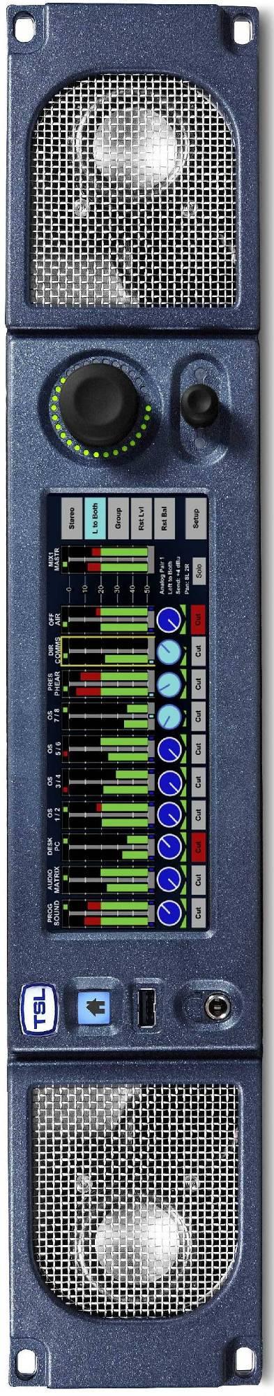
12 P a g e Controls and Displays - Overview 4-Driver Loudspeaker System Home Preset Instant Recall Dual Action Monitoring Level Control w/cut, Dim. CLEAN LIVE OB ST. PGM PGM PGM AES OFF NO MIX 1 FX MIC1 COMMS PGM L R C LFE LS RS MON AIR INPUT MSTR 0 Stereo Mono LCR Dmix Rst Lvl USB Port for Field Upgrades and System Backup Cut Cut Cut Cut Cut Cut Cut Cut Cut Cut 22:9 Aspect Ratio LCD Touch Screen AVM-T-MIX is equipped with a 4 driver loudspeaker system comprising left/right tweeter and dual subwoofer units. Menus and features are navigated via the 22:9 aspect ratio touch screen. The front panel USB connector is used for software upgrades; favourite user preset storage and preset recall. User presets can be recalled and stored locally using the Home button. Loudspeaker and headphone volume is adjusted by the master level control. This dual action rotary encoder also features push to Cut/Dim functionality. The dual function rotary encoder is rotated to control channel level send with pan/balance activated by push and turn. SDI 1 pair 1 LCR DMIX Send: 0.0dB Bal: L = R Solo Rst Bal Setup Dual Function Encoder Level Send/Push for Pan/Balance
13 P a g e 13 Touch and Hold Bargraph for Source Selection Touch and Hold Mix Master Bargraph to Select Mix 1 or Mix 2 Input configurations Input Channel Format Selection Level Send and Bal/Pan Indication Stereo/Mono/Group Channel Status Touch and Hold channel bargraph to activate input selection menu. Upon selection of input, selected channel format is selected via the Stereo/Mono/Group buttons. Selected channel send and Bal/Pan level indicated by icons below bargraph display. Stereo/Mono/Group channel format denoted by colour of level send control and pips beneath bargraph pairs. Individual channels can be cut from main mix buss. Individual Channel Cut Switch Individual channels can be soloed to monitoring output buss. Selected Channel Status and Solo Button AVM-T-MIX features two entirely independent Audio Mixers. Touch and Hold Mix Master Bargraph to toggle between Mixer 1 and Mixer 2.

14 P a g e 14 Input Channels with 10 Character User Unused Input Channels Routed to No Input Channels defined as Group in either 2 Pair, 5.1 or LRC formats Channel defined as Mono, Left Only or Right Only formats Channel defined as Stereo format Input sources named with a user defined 10 character mnemonic displayed above the channel bargraph. Unused input channels can be routed to Silence displayed as No Input. Channel Group format is denoted by use of Magenta colouration. Channel Group formats include 2 Pair, 5.1 Downmix and LRC Downmix (as shown above). Channel Stereo format is denoted by use of Electric Blue colouration. Channel Mono format is denoted by use of Cyan colouration. Selected Channel overview including Input Source, Format, Send level and Bal/Pan Channel Mono formats include L+R, Left to both and Right to both (as shown above). Selected Channel status shown in information box includes Source, Format, Send level and Bal/Pan adjustment.
. Each can be configured with its own setup and used in diverse applications.")

15 P a g e Source Selection Key to the ease of operation of AVM-T-MIX is the simplicity by which audio may be monitored and/or mixed. As described previously, AVM-T-MIX is equipped with two completely independent mixer/monitor systems (Mixer 1 and Mixer 2). Each can be configured with its own setup and used in diverse applications. Mixer 1 may be used as primary audio monitor in any application whilst the secondary mixer might be used as a simple de-embedder to back-feed another part of the system or even as a means to derive a headphone cue to a voice over artist or commentator. Setting up the monitor for use is simple and intuitive yet incredibly powerful. AVM-T-MIX Source Selection AVM-T-MIX SD Source Selection By simply touching and holding the desired channel the SOURCE menu selection is automatically activated. Select the signal type/pair or SILENCE if no selection is required and the chosen audio will be routed to the channel pair. If the selected input has been configured with a User Name then the text string will be displayed above the bargraph pair. Audio is automatically routed to the selected channel from an active input and the signal activity displayed on the bargraph. To hear the incoming audio instantly, simply press SOLO and turn up the volume. Touch BACK to exit the SOURCE menu.
16 P a g e Analogue Audio Input Trim AVM-T-MIX is designed to be used with balanced or unbalanced analogue audio inputs. If one of the analogue inputs has been wired to an unbalanced signal source then the user may need to compensate for signal loss (typically -6dB). If this is the case then gain can be added to the chosen analogue input in steps of 3dB by touching the button displayed below via the Setup/Input menu. Please note that the AVM-T-MIX does not have an analogue signal amplifier and that the gain is added in the digital domain. If gain is added to an unbalance analogue audio input in this way then the signal to noise ratio of that signal will be affected accordingly and low level hiss may be heard in exceptional circumstances. Press to access Input Trim for low level or unbalanced analogue audio


17 P a g e Channel Signal Format Selection Channel formats can be defined as Stereo, Mono or a Group of 2 or more pairs (including 5.1 and LRC Downmix configurations) Stereo Channel Format: To define a channel as Stereo, simply touch the desired bargraph pair followed by the STEREO button from the Format menu (as shown). The Level Send and format Pips below the bargraphs denote Stereo selection by the use of Electric Blue colouration Mono Channel Format: To define a channel as Mono, simply touch the desired bargraph pair followed by the MONO button from the Format menu (as shown). The MONO L/R menu is then activated enabling the operator to choose between L+R, Left to Both and Right to Both formats. The Level Send and format Pips below the bargraphs denote Mono format selection by the use of Cyan colouration Group Channel Format: There are four modes of selection within the GROUP menu designed to enable the user to mix and monitor sources delivered in more complex channel formats Group 2 PAIR ADD: 2 Pair Additive mode sums two adjacent stereo audio pairs together in the format L+L and R+R. The user can adjust the level of the left sum against right via the balance control Group 2 PAIR OFF: 2 Pair Offset mode sums two adjacent stereo audio pairs together in the format L+L and R+R however unlike the 2 PAIR ADD mode, the balance control is used to adjust the relative mix of Pair One against Pair Two. Pair Offset mode is particularly useful for adjusting the balance of monitored audio when source material comprises a clean FX track on pair one and a commentary on pair two as is often common in Sports Broadcasting. Pai Group 5.1 DMIX: 5.1 Downmix mode sums 3 adjacent pairs in an Lo Ro stereo format assuming that a standard 5.1 configuration track order has been adhered to (L/R/C/LFE/Ls/Rs) as shown in the image above. In 5.1 Downmix mode the LFE channel does not form part of the stereo sum. The user can adjust the level of the left sum against right via the balance control. The 5.1 Downmix algorithm follows the formula L+(C-3dB) + (Ls-3dB), R+(C-3dB) + (Rs-3dB).
18 P a g e 18 A user selectable adjustment located within the menu Setup/Setup2/DMIX enables selection of the a Surround -6dB) coefficient with the resultant formula L+(C-3dB) + (Ls-6dB), R+(C-3dB) + (Rs-6dB) active depending on the selection Group LRC DMIX: LRC Downmix mode sums 2 adjacent pairs together as a stereo signal with the first channel of the second pair summed equally to the Left/Right channels. The user can adjust the level of the left sum against right via the balance control. The LRC Downmix algorithm follows the formula L+(C-3dB), R+(C-3dB) The Level Send and format Pips below the bargraphs denote a Group format selection by the use of Magenta colouration

19 P a g e Monitoring Input Channels Solo Function Similar to a traditional rackmount audio monitoring unit, the AVM-T-MIX is used to listen to incoming signal sources either exclusively or additively. The simplest way to achieve this is to touch the bargraph channel you wish to hear and then to select SOLO. The selected signal will automatically be routed to the loudspeakers (internal or external) and to the headphone socket. The example above shows how an operator can quickly check an incoming Programme audio signal which has been Downmixed to stereo from 5.1. In SOLO Mode. He/she can now simply touch the adjacent 5.1 bargraph group labelled PGM2 in order to compare the two signals or alternatively touch the SOLO buttons beneath another bargraph pair to add the signals to the monitoring output. The selected SOLO channels are automatically routed at unity gain to the output as denoted by the position of the rotary SEND icon. In SOLO mode, any MIXER routing configurations on either MIXER 1 or MIXER 2 are unaffected.

20 P a g e Monitoring Input Channels Mixer Function One of the unique advantages of AVM-T-MIX over a more traditional Audio Monitoring Unit is the ability to mix sources together using the same methods found in assignable digital audio mixing consoles. Mixer 1 and Mixer 2 are both equipped with main outputs which are routed to the monitoring outputs (loudspeakers and headphones) and to fixed line level Analogue and AES connections. Individual bargraph channels can be mixed onto Master Output bargraphs by adjusting the send level of the selected (highlighted by the yellow box ) channel using the small rotary encoder simply by turning it clockwise. By pushing and turning the encoder it is possible to adjust the Balance (for Stereo and Downmixed sources) or Pan (Mono) of the selected output being sent to the Mixer Master output. The example above depicts a typical Lines Room application where the operator is monitoring 3 different incoming language feeds as LRC Downmixes embedded within the SDI infrastructure on channels 1 thru 6. He/She is simultaneously listening to audio traffic via an AES router (channels 7 and 8) of Stereo Telco feeds 1 and 2 from another location plus a mix of local and remote mono Talkback on channels 9 and 10. The Talkback inputs from the Outside Broadcast and local Studio are panned to the left and right channels respectively to give separation against the Clean/Native Language Downmix coming from the OB event. Channels 3 and 4 plus channels 5 and 6 contain Clean/Alternative Language Downmixes which are being generated locally from Voice Over Booths with French and German Commentators. Mixer 2 line level outputs can be used in this application to provide a Submix of the Clean International Audio plus Local and OB Talkback to the Commentators via their local headphone amplifiers.
 audio mixers designed to enable the operator to create their own custom monitoring")

21 P a g e Audio Mixers 1 and 2 The AVM-T-MIX is equipped with two identical but independent 20 channel (10 stereo bargraph) audio mixers designed to enable the operator to create their own custom monitoring setups. On first power up, AVM-T-MIX displays the bargraphs associated with Mixer 1 as denoted by the mnemonic MIX 1 MASTER above the output bargraph pair as shown below. Initial Power Up: Mixer 1 Input and Output Channels Simply touching the Mix Master 1 bargraph for a few seconds will toggle the display between Mixer 1 and Mixer 2; each mixer can be configured entirely independently as described in the following sections of this Handbook by simply touching and holding any of the 10 bargraph pairs. 2.8 Configuring and Naming Input Channels The physical audio connections into AVM-T-MIX comprise of 16 channels from HD-SDI (16 channels SDI 1, 8 channels SDI 2)), 8 AES pairs and 16 (or 8 stereo) analogue audio inputs. Each pair can be routed to any of the 10 channel bargraphs available to either Mixer 1 or Mixer 2 and to simplify operation, each input pair can be given a User Name. In order to simplify the naming of input sources the AVM-T-MIX is equipped with an onscreen QWERTY style keyboard which can be accessed via the Setup/Input menu page. To apply a name to an input source simply select the appropriate pair, press CLEAR to delete the default name and enter the chosen replacement in the dark grey field. Press DONE when complete.
22 P a g e 22 User names can be up to 10 characters long and can consist of upper/lower case letters, numbers and a very limited set of symbols - _ and. When entering a text string AVM-T-MIX will automatically enter a space between the 5 th and 6 th characters unless the user inserts a space at any other point within the name. When a signal with an associated User name is routed to a channel bargraph, the name is displayed above the bargraph in two rows of text with up to 5 characters in each.

23 P a g e User Preset and Snapshot Management Home Button and User Presets AVM-T-MIX uses both internal and external User Preset memories to enhance usability, there are a total of 18 User Presets in local memory plus a Snapshot which is defined as HOME enabling operators to instantly revert to a default operational condition. A User Preset is defined as a Snapshot of a state of operation and includes the following parameters; MIXER 1 and MIXER 2 Channel Source Selection Channel Output Send Levels Channel Pan/Balance Channel Format Selection Input User Names Bargraph Configuration (including Scale, Ref, Zero etc.) GPI Mode Internal LS Mute Status External LS Mute Status Surround Mix Coefficient User Preset Name AVM-T-MIX total of 18 Internal Memories can be backed up to a USB memory stick (front panel port) or SD Card (rear panel slot). Access to the USER PRESET/HOME menus is via the front panel HOME button User Presets SAVE Menu Holding down the HOME button for approximately 3 seconds accesses the SAVE menu. This menu page allows the operator to create and save snapshot memories, to backup the onboard memories to an external device or to configure the HOME preset. Set Home Pressing the Set Home button will automatically store the current operational configuration to the Home snapshot location.
, enter a name using the QWERTY keyboard (press Clear to remove the default name) and Save to store.")

24 P a g e 24 Set User Pressing the Set User button enables the operator to store the current operational configuration to any of the 18 internal memory locations. The following menu will appear; Simply select the desired internal memory location (User 1-18), enter a name using the QWERTY keyboard (press Clear to remove the default name) and Save to store. USB Save Pressing the USB Save button (only active when a USB Stick is inserted) enables the operator to backup all 18 internal memories to an external memory device. If an SD card is used via the rear panel then the AVM-T-MIX will save to that device. If both a USB and an SD device are inserted simultaneously, the USB location will take precedence. The USB Save menu will ask the operator to confirm if they wish to replace an existing memory file before completing a backup.


25 P a g e User Presets Recall Menu Pressing the HOME button momentarily accesses the Recall menu. This menu page allows the operator to recall saved snapshot memories, to recall memories from an external device and to instantly recall the HOME snapshot. Recall Home Pressing the Recall button will automatically load the stored Home snapshot from internal memory. If no Home snapshot has been stored, the default shipping condition will be reloaded. Get User Pressing the Get User button enables the operator to load any of the 18 internal user presets from memory. User Presets are displayed in groups of 6, pages 1 to 3 are recalled via the More button. USB Load Pressing the USB Load button (only active when a USB Stick is inserted) enables the operator to restore all 18 internal memories from an external memory device.


26 P a g e Setup Menu Setup Menu includes options for different Scales, Reference Levels, Peak Hold, Input Naming and access to the Setup 2 Menu. By simply touching the appropriate button, individual sub menus are selected Meter Menu Pressing the Meter button accesses the bargraph scale options. AVM-T-MIX is able to accurately replicate EBU Digital, EBU PPM, BBC PPM, DIN PPM, Nordic PPM and VU scales and ballistics. Please note that the selection of a scale type within the Meter screen will only be remembered by AVM-T-MIX as a preset once the selection has been saved to internal memory using the User Preset commands described previously. This restriction enables the user to save preset conditions which work using different bargraph scales.
27 P a g e dbfs Menu The dbfs parameter selection can be used to alter the 0dBu reference level from between -12 and -24 dbfs Meter Peak Menu The Peak parameter selects the offset level between the Reference dbfs setting and the onset of Peak indication (the point where the bargraph changes colour to red) from between +1dB and +18dB Meter Zero Menu The Meter Peak selects between two modes of peak indication displayed on the channel bargraphs. The Bar Mode illuminates the bargraph as red once the audio level exceeds the peak value. In Block Mode the bargraph illuminates in yellow when the audio level exceeds the reference value and then red when it exceeds peak (as illustrated below).
28 P a g e Meter Hold Menu AVM-T-MIX features a simple Peak Hold indicator which may be turned on and off using the Meter Hold Menu Setup 2 Menu Setup 2 Menu includes options to protect User Presets, GPI Action, External and Internal Loudspeaker Mute, Surround Downmix Coefficients and to access the Software Management Menu User Save Menu The User Save Menu enables an Engineer or Technician to Lock or Unlock the User Preset management system onboard AVM-T-MIX. In Locked mode a user is able to recall the Home Preset but unable to save or recall memories from internal or external (USB or SD Card) locations.
29 P a g e GPI Menu The GPI Menu enables an Engineer or Technician to select whether GPI inputs respond to Latching or Momentary closures from external devices. The GPI connector can be used to Cut/Dim the internal and external Loudspeakers, recall Home preset and to recall User presets 1 to 7. The pin-out is described in Section 3.5. In Momentary Mode, Dim and Cut GPI's latch in a toggle manner, i.e. one closure to ground toggles the function ON; the next ground toggles it OFF. In an ON state; the GPI pin is driven low to allow an LED to be fed from the port. This LED drive is briefly pulsed high at about 100Hz to allow the port to be read whilst it is driving. The preset recall GPI s in Latching mode are mutually exclusive Internal / External Loudspeaker Mute The AVM-T-MIX is designed to be used with either Internal or External Loudspeaker Systems. Users may wish to define User Preset conditions which associate the operation of the unit with internal speakers for in one state and external speakers in another. To facilitate this kind of hybrid operation the AVM-T-MIX is equipped with individual Loudspeaker Mute buttons which can be configured with different functionality dependant upon their desired use and then saved to individual presets. In the event that AVM-T-MIX is installed for use with external speakers only with the intention to mute the internal speakers, a DIP switch on the rear panel can be used to override the Internal LS Mute button in Setup 2 Menu.

30 P a g e Surround Mix Menu The S-MIX Menu provides a means to select the Downmix coefficient by which the Rear Surround Loudspeaker audio channels are added to the Front Left and Right when a Group/5.1 DMIX mode is selected. When -3dB is selected, the 5.1 DMIX feature creates a stereo fold-down of the 5.1 channels using the following algorithm; L= L + (Ls -3dB) + (C -3dB); R= R + (Rs -3dB) + (C -3dB) When -6dB is selected, the 5.1 DMIX feature creates a stereo fold-down of the 5.1 channels using the following algorithm; L= L + (Ls -6dB) + (C -3dB); R= R + (Rs -6dB) + (C -3dB) 2.12 Software Menu TSL is committed to providing customers with free life of product software updates as the features of AVM-T-MIX evolve and any bugs are addressed. New code is made available via our reseller distribution channels and as a download from the TSL website. System Software may be updated by the owner via either the front panel USB Port (using a USB memory stick) or the rear panel SD Slot. Accessing the path Setup/ Setup2/ SWare the AVM-T- MIX will enter a menu page which reports the current software versions of the onboard Front Panel driver board (FP4), FPGA and PIC devices on the upper three information fields. If a memory device is inserted containing a software revision the three update fields will be displayed as illustrated below;

31 P a g e 31 In order to commence the upload sequence, simply press the UPDATE button and the FP4, FPGA, and PIC code will be loaded in order. Progress in indicated via the 0-100% scale. Once complete, AVM-T-MIX will display a message confirming that the process has been successfully concluded prompting the user to perform a factory reset. To perform a factory reset it is necessary to remove power from the unit and then re-apply power whilst pressing the Home button until a message appears to confirm that Factory Default has been reloaded. Press Home once more and you will be able to operate AVM-T-MIX with the new firmware active. The action of restoring Factory Default status will remove any stored memories from the AVM-T-MIX. Please backup and restore memories from an external device if required. Please note that the UPGRADE sequence may take several minutes and may appear to stall it is important not to interrupt the process or to remove power from the device during a software upload as this may render the AMU unusable.
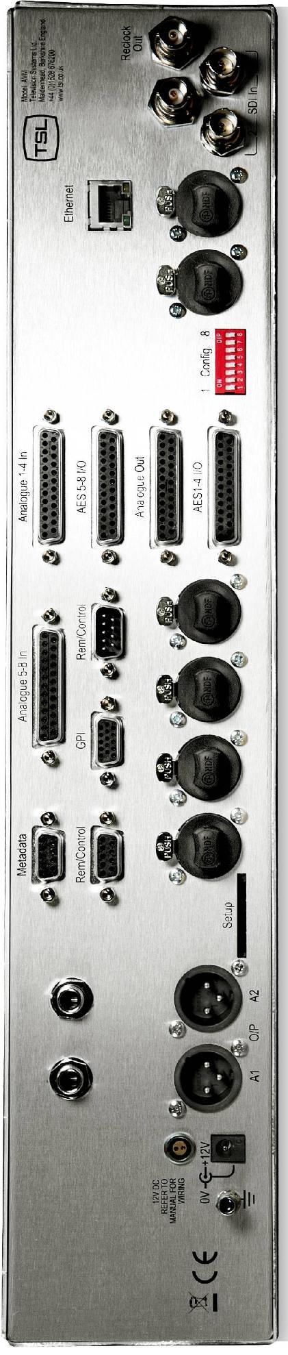
32 P a g e Connectivity and pin-out details AVM-T-MIX uses industry standard connectivity wherever possible. The D25 connectivity used for analogue and AES I/O adopts a pinning convention commonly used for Yamaha Commercial Audio equipment and breakout cables are readily available at low cost from companies such as and many others. For unbalanced AES I/O connectivity an optional BNC breakout cable, CAB-D25-BNC, is available from TSL or your local reseller. When used in conjunction with AVM-T-MIX, DIP switch 2 (AES Impedance) must be switched to the 75 ohm position. 3.1 Analogue XLR Connectors Stereo Variable Output (Monitor Buss) CONN PIN FUNCTION ANALOG 1 1 GND ANALOG IN+ ANALOG IN- ANALOG 2 1 GND ANALOG IN+ ANALOG IN- 3.2 Analogue Output Connector D25 Socket Pinout on unit, Plug (shown) on mating cable. D 25 SOCKET ON AMU AUDIO OUT PIN NO FUNCTION 1 A8+ (Var. Mon R) 14 A8- (Var. Mon R) 2 Ground 15 A7+ (Var. Mon L) 3 A7- (Var. Mon L) 16 Ground 4 A6+ (Fixed Mon R) 17 A6- (Fixed Mon R) 5 Ground 18 A5+ (Fixed Mon L) 6 A5- (Fixed Mon L) 19 Ground 7 A4+ (Fixed Mix 2R) 20 A4- (Fixed Mix 2R) 8 Ground 21 A3+ (Fixed Mix 2L) 9 A3- (Fixed Mix 2L) 22 Ground 10 A2+ (Fixed Mix 1R) 23 A2- (Fixed Mix 1R) 11 Ground 24 A1+ (Fixed Mix 1L) 12 A1- (Fixed Mix 1L) 25 Ground 13 N/C
33 P a g e Analogue Input Connectors 1-4 and 5-8 D25 Socket Pinout on unit, Plug on mating cable. D 25 SOCKET ON AMU AUDIO IN PIN NO FUNCTION 1 A4 (A8) R+ 14 A4 (A8) R+ 2 Ground 15 A4 (A8) L- 3 A4 (A8) L- 16 Ground 4 A3 (A7) R+ 17 A3 (A7) R- 5 Ground 18 A3 (A7) L+ 6 A3 (A7) L- 19 Ground 7 A2 (A6) R+ 20 A2 (A6) R- 8 Ground 21 A2 (A6) L+ 9 A2 (A6) L- 22 Ground 10 A1 (A5) R+ 23 A1 (A5) R- 11 Ground 24 A1 (A5) L+ 12 A1 (A5) L- 25 Ground 13 N/C
34 P a g e AES Input/Output Connectors 1-4 and 5-8 D25 Socket Pinout, Plug (shown) on mating cable. D 25 SOCKET ON AMU AES INPUTS/OUTPUTS PIN NO FUNCTION 1 Ch1&2 / 9&10 In Ch1&2 / 9&10 In 1-2 Ch3&4 / 11&12 In Ch3&4 / 11&12 In 2-3 Ch5&6 / 13&14 In Ch5&6 / 13&14 In 3-4 Ch7&8 / 15&16 In Ch7&8 / 15&16 In 4-5 Ch1&2 Fixed Mix 1 / 9&10 Out Ch1&2 Fixed Mix 1 / 9&10 Out 1-6 Ch3&4 Fixed Mix 2 / 11&12 Out Ch3&4 Fixed Mix 2 / 11&12 Out 2-7 Ch5&6 Fixed Mon / 13&14 Out Ch5&6 Fixed Mon / 13&14 Out 3-8 Ch7&8 Var. Mon. / 15&16 Out Ch7&8 Var. Mon. / 15&16 Out 4-9 N/C 22 Ground 10 Ground 23 Ground 11 N/C 24 Ground 12 Ground 25 Ground 13 Ground AES connectors may be wired using unbalanced terminations for SPDIF and 75R coaxial systems. Optional AES breakout cable CAB-D25-BNC-2 is available from TSL Sales ( ) and provides BNC Socket to D25 connectivity. Please note that when using AVM-T-MIX with unbalanced AES audio connections that the 75/110 ohm DIP Switch must be selected prior to use. When using the D25 for unbalanced AES, AES XLR connectors 1 and 2 may not be used for balanced AES connectivity.
35 P a g e GPI Connector HD15 Socket. GPI pins are as follows: o Dim - pin 6 o Cut - pin1 o Home - pin 11 o User Preset 1 - pin 7 o User Preset 2 - pin 2 o User Preset 3 - pin 12 o User Preset 4 - pin 8 o User Preset 5 - pin 3 o User Preset 6 - pin 13 o User Preset 7 - pin 9 o +5V - pin 5 o 0V pin 15 o pins 4, 14, 10 unused at this time 3.6 Remote Control Connector/ RS D9 Socket This is wired for RS422 slave operation. D9 CONTROL 1 0V 6 0V 2 TX- 7 TX+ 3 RX+ 8 RX- 4 0V 9 0V 5 N/C 3.7 DIP switch configuration functions To be confirmed SWITCH FUNCTION 1 tbc 2 AES Impedance (75R Up/110R Dn) 3 Internal LS Mute (Mute Up/On Dn) 4 tbc 5 tbc 6 Analogue (XLR) Output (Fixed/Variable) 7 tbc 8 tbc
36 P a g e Notes There are no user adjustable assemblies/components within this unit. This unit requires rear support when rack mounted. In order to affect status changes of the unit using the rear DIP switch, the unit will require re powering before the changes take effect. Output analogue levels are adjustable over the following range: 0dBm = 0.775V into 600Ω i.e. 1mW power dissipation. 0dBu = 0.775V RMS = PPM 4. Shipping condition, -18 db ref 0FS = 0dBu output. Typical European line up: -18 dbu Typical American line: -20 dbu
37 P a g e General Notes Please note that some American equipment has the function of the XLR pins 2 & 3 reversed. TSL product is wired to the European standard The screw locks on the D25 connectors use UNC 4-40 standard threads. 6.0 AVM TOUCH SERIES - Technical Specifications Power Supply Supply Voltage 12V DC Power Consumption tbc. Physical Dimensions Height 88mm (2RU) Width 483mm (19 ) Depth 320mm Weight 5100g Inputs AES 1 to 8 AES I/O, 25 way D type (See elsewhere for details) Input, HD/SDV 1 &2 (where fitted) Connector Type BNC. Standard 4:2:2 component with embedded 48Khz audio. (SMPTE 259M, 292M and 424M) Impedance 75ohm Line Output. Connector XLR 3 pin Male Impedance 50Ω Output Levels Through level control with 0dB gain. Fixed Line O/P Available on D25 (If selected on front panel) Headphone Output. Connector Stereo Jack socket type A Impedance 50Ω Output Levels Through level control with 0dB gain. Video Output Connector BNC Impedance 75 Ohm Output Composite video or SDI (selectable) Re-clocked Output Connector BNC Impedance 75 Ohm Output Re-clocked serial output of the SELECTED input HD/SDV AES Output Connector Impedance AES I/O, 25 way D type (See elsewhere for details) 110/75 Ohm HD Standards Supported 1080i/ p/ i/ i/ p/ i/ i/ p/ sf/ P/ p/ sf/29.97
38 P a g e P/ p/ sf/ P/ i/ sf/24 720p/ i/ sf/ p/ i/30 720p/60 480i/30.00 (SD - NTSC) 576i/25.00 (SD - PAL) Performance Response 70Hz to 20KHz Electrical Distortion Better than 0.1% Hum and noise Better than -80dB SPL >98dB at 0.6 m Amplifier Output 40 watts total power output Digital Sample Rate 32 to 48KHz auto select
39 P a g e Installed HDC-2T Audio Monitor Module Specification (including add on expansion board). Overview This specification describes the HDC-2T Audio Monitor Module. This module has been designed to monitor a combination of analogue audio, AES3 digital audio and AES or Dolby E digital audio embedded in SMPTE 259M or SMPTE 292M video data streams, together with the video content which is output as composite and/or SDI. HD formats are passed through a simple down-conversion process to the monitoring output. Mechanical PCB: Component Height: Power 4 layer, 120mm x 376mm with integral BNC and XLR connectors <30mm above pcb surface, <2mm below <65mm above pcb surface with Dolby E fitted The module assumes the supply of regulated power will be made available via the power input connector. Poorly regulated or noisy supply rails may affect the quality of the analogue outputs. The HDC-2T will accept two feeds of +12V to +24V DC power, approximately 60W typical when using loudspeaker outputs. This allows dual redundant or external battery operation. Inputs HD/SDI Connector Type: Receiver type: Impedance: Standards: BNC AC coupled, auto equalising with clock regeneration 75Ω, return loss 15dB to 1.5GHz SMPTE 259M-C with embedded 48kHz audio per SMPTE 272M-A SMPTE 292M with embedded 48kHz audio per SMPTE 299M Performance: 300m of high quality cable at 270Mbit (eg Belden 1694) 100m of high quality cable at 1.5Gbit AES 3 or AES 3id Connector type: Inputs 1 & 2, XLR 3 pin. (can be built for unbalanced BNC input) Inputs 1, 2, 3 & 4. 25way D-type 4 stereo pairs, pin-out as per Yamaha Impedance: 75Ω unbalanced or 110Ω balanced. Impedance is switch selected via DIP Switch 2. To obtain an unbalanced connection one line of the input needs to be grounded at an electrically convenient point. Input Sensitivity: < 200mV p-p per AES3. Standards: AES at 96 khz, 48kHz, 44.1kHz or 32kHz Analogue Inputs Connector type: Board header Remote control Connector type: Outputs Video 4 x XLR 3 pin, (Two stereo pairs) Further 4 stereo pairs (8 channels) Header, 10way to connect to 9pin D-type (RS422) Connector Type: BNC Output 1 Equalised active loop-through Impedance: 75Ω Amplitude: 800mV p-p ±10% Output 2 Composite SD (Down-converted when input is HD) Format: PAL or NTSC according to standard on SDI input Impedance: 75Ω Amplitude: 1V p-p ±5% Output 3 - Optional SDI version of image on composite output Impedance: 75Ω Amplitude: 800mV p-p ±10%
40 P a g e 40 AES Eight AES (16 channels) may be output from analogue audio, embedded audio. Connector type: 25way D-type 4 AES pairs (In and Out), pin-out as per Yamaha Standard Impedance: 75Ω unbalanced or 110Ω balanced. Impedance is switch selected with on-board transformer balancing. To obtain an unbalanced connection one line of the output needs to be grounded at an electrically convenient point. Amplitude: 1V into 75Ω or >2V into 110Ω Analogue Audio Eight analogue channels (4 stereo pairs) that may be output from AES, embedded audio or from decoded Dolby E/D when the option is fitted Connector Type: XLR one pair fixed or variable 25 way D type 4 stereo pairs, pin-out as per Yamaha/Tascam Format: Electronically balanced, centre ground. D/A Conversion: 24 bit resolution. THD+N: >80dB referred to 0dBFS Loudspeakers Connector Type: board header Format: Two active cross-over or 4 broad-band loudspeaker outputs 10 to 40W (4Ω) per channel into depending on input power supply GPI inputs Connector type: Control Connector type: Connector type: Header to 9-way D-type plug Header for current AMU-1 operator control board Header, serial bus for future operator control/display panels
SAFETY. Unless otherwise stated TSL equipment may be installed at any angle or position within an -
 P a g e 2 SAFETY Installation. Unless otherwise stated TSL equipment may be installed at any angle or position within an - All TSL equipment conforms to the EC Low Voltage Directive: EC Low Voltage Directive
AMU2-2MHD+ Audio monitoring Unit
 AMU2-2MHD+ Audio monitoring Unit Handbook TSL Vanwall Road, Maidenhead, Berkshire, SL6 4UB Telephone +44 (0)1628 676200, FAX +44 (0)1628 676299 AMU2-2MHD+-6 1 ISSUE 5 SAFETY Installation. Unless otherwise
AVMU2-BHD+/3G Audio monitoring Unit
 AVMU2-BHD+/3G Audio monitoring Unit Handbook Television Systems Limited. Vanwall Road, Maidenhead, Berkshire, SL6 4UB Telephone +44 (0)1628 676200, FAX +44 (0)1628 676299 AVMU2-BHD+/3G 1 ISSUE 3 SAFETY
AMU1-BHD+ Audio monitoring Unit
 AMU1-BHD+ Audio monitoring Unit Handbook TSL Vanwall Road, Maidenhead, Berkshire, SL6 4UB Telephone +44 (0)1628 676200, FAX +44 (0)1628 676299 AMU1-BHD+-6 1 ISSUE 6 SAFETY Installation. Unless otherwise
AMU2-8HD+ & 3G Audio Monitoring Units Handbook TSL Vanwall Road, Maidenhead, Berkshire, SL6 4UB
 AMU2-8HD+ & 3G Audio Monitoring Units Handbook TSL Vanwall Road, Maidenhead, Berkshire, SL6 4UB Telephone +44 (0)1628 676200, FAX +44 (0)1628 676299 AMU2-8HD+/3G 1 Issue 1 SAFETY Installation. Unless otherwise
S1 Digital/Analogue Radio Broadcast Mixer September 2009
 S1 Digital/Analogue Radio Broadcast Mixer September 2009 www.sonifex.co.uk t: +44 (0)1933 650 700 f: +44 (0)1933 650 726 sales@sonifex.co.uk S1 Radio Digital/Analogue Broadcast Mixer Radio Broadcast Mixer
S1 Digital/Analogue Radio Broadcast Mixer
 S1 Digital/Analogue Radio Broadcast Mixer September 2009 www.sonifex.co.uk t: +44 (0)1933 650 700 f: +44 (0)1933 650 726 sales@sonifex.co.uk S1 Radio Digital/Analogue Broadcast Mixer Radio Broadcast Mixer
BM- AV1- E16SHD Manual BM-AV1-E16SHD. 16 Channel Digital Audio Monitor. User s Guide. Version /01/2013. Version 2.
 Manual BM-AV1-E16SHD 16 Channel Digital Audio Monitor User s Guide Version 2.1 14/01/2013 Version 2.1 Page 1 BEL (Digital Audio) Ltd., has made every effort to ensure the accuracy of information contained
S0 Radio Broadcasting Mixer. June catalogue. Manufacturers of audio & video products for radio & TV broadcasters
 S0 Radio Broadcasting Mixer June 2012 catalogue Manufacturers of audio & video products for radio & TV broadcasters S0 Radio Broadcasting Mixer A simple radio mixer for novice and professional users The
DRAFT RELEASE FOR BETA EVALUATION ONLY
 IPM-16 In-Picture Audio Metering User Manual DRAFT RELEASE FOR BETA EVALUATION ONLY Ver 0.2 April 2013 1 Contents Introduction...3 In Picture Audio Meter Displays...4 Installation...7 External Audio Board
BM-A1-E16SHD V2.2. Manual BM-A1-E16SHD. 16 Channel Digital Audio Monitor. User s Guide. Page 1
 BM-A1-E16SHD V2.2 Manual BM-A1-E16SHD 16 Channel Digital Audio Monitor User s Guide Page 1 BEL (Digital Audio) Ltd., has made every effort to ensure the accuracy of information contained within this document,
FWD8000 Dante enabled four wire box
 FWD8000 Dante enabled four wire box by CTP Systems Product warranty This unit is guaranteed for a period of one year from dispatch of the goods. This guarantee is a return to base warranty. In the unlikely
AES-402 Automatic Digital Audio Switcher/DA/Digital to Analog Converter
 Broadcast Devices, Inc. AES-402 Automatic Digital Audio Switcher/DA/Digital to Analog Converter Technical Reference Manual Broadcast Devices, Inc. Tel. (914) 737-5032 Fax. (914) 736-6916 World Wide Web:
AES-404 Digital Audio Switcher/DA/Digital to Analog Converter
 Broadcast Devices, Inc. AES-404 Digital Audio Switcher/DA/Digital to Analog Converter Technical Reference Manual Broadcast Devices, Inc. Tel. (914) 737-5032 Fax. (914) 736-6916 World Wide Web: www.broadcast-devices.com
AES Channel Digital/Analog Audio Switcher/DA/Digital to Analog Converter
 Broadcast Devices, Inc. AES-408 8 Channel Digital/Analog Audio Switcher/DA/Digital to Analog Converter Technical Reference Manual Broadcast Devices, Inc. Tel. (914) 737-5032 Fax. (914) 736-6916 World Wide
FF DUAL FORMAT DJ MIXER USERS MANUAL
 FF - 4000 DUAL FORMAT DJ MIXER USERS MANUAL FF - 4000 INTRODUCTION The features and layout of the FF-4000 were determined in collaboration with leading loudspeaker manufacturers Funktion One, who canvassed
ANALOG RADIO MIXER. Flexible. Affordable. Built To Last.
 ANALOG RADIO MIXER Flexible. Affordable. Built To Last. Audioarts AIR-4 A N A L O G R A D I O M I X E R At Audioarts, value engineering is straightforward: Define the features our customers require. Design
MODULAR I/O DIGITAL AUDIO CONSOLE. Flexible. Affordable. Built To Last.
 MODULAR I/O DIGITAL AUDIO CONSOLE Flexible. Affordable. Built To Last. 2 Audioarts X-12 Digital MODULAR I/O DIGITAL AUDIO CONSOLE There was a time when handling digital audio was an option. Not anymore.
3G/HD/SD dual channel audio embedder/de-embedder
 3G/ dual channel audio embedder/de-embedder Dual channel audio embedder/de-embedder, with two independent video channels Being dual channel makes the audio embedder/de-embedder perfect for those pricesensitive
C8000. sync interface. External sync auto format sensing : AES, Word Clock, Video Reference
 features Standard sync module for a frame Internal sync @ 44.1 / 48 / 88.2 / 96kHz External sync auto format sensing : AES, Word Clock, Video Reference Video Reference : Black Burst (NTSC or PAL) Composite
Solid State Logic S O U N D V I S I O N
 Solid State Logic S O U N D V I S I O N SUPERANALOGUE X - R A C K Super-Analogue Outboard XR622 X-Rack Master Module User s Guide This documentation package contains the User s Guide for your new X-Rack
CEDAR Series. To learn more about Ogden CEDAR series signal processing platform and modular products, please visit
 CEDAR Series The CEDAR platform has been designed to address the requirements of numerous signal processing modules. Easily-installed components simplify maintenance and upgrade. To learn more about Ogden
Model 5250 Five Channel Digital to Analog Video Converter Data Pack
 Model 5250 Five Channel Digital to Analog Video Converter Data Pack E NSEMBLE D E S I G N S Revision 3.1 SW v2.0.1 This data pack provides detailed installation, configuration and operation information
C8491 C8000 1/17. digital audio modular processing system. 3G/HD/SD-SDI DSP 4/8/16 audio channels. features. block diagram
 features 4 / 8 / 16 channel LevelMagic2 SDI-DSP with level or loudness (ITU-BS.1770-1/ ITU-BS.1770-2, EBU R128) control 16 channel 3G/HD/SD-SDI de-embedder 16 in 16 de-embedder matrix 16 channel 3G/HD/SD-SDI
User s Guide Version /01/2012
 BM- A2-16SHD 2012 BM-A2-16SHD 16 Channel Digital Audio Monitor User s Guide Version 1.0 01/01/2012 Version 1.0 Page 1 BEL (Digital Audio) Ltd., has made every effort to ensure the accuracy of information
BM-A2-4SHD MKII. Ver Channel Digital Audio Monitor. User s Guide. Page 1
 BM-A2-4SHD MKII BM-A2-4SHD MKII 4 Channel Digital Audio Monitor User s Guide Page 1 BEL (Digital Audio) Ltd., has made every effort to ensure the accuracy of information contained within this document,
Model 7600 HD/SD Embedder/ Disembedder Data Pack
 Model 7600 HD/SD Embedder/ Disembedder Data Pack E NSEMBLE D E S I G N S Revision 2.1 SW v2.0.1 This data pack provides detailed installation, configuration and operation information for the 7600 HD/SD
Model 6010 Four Channel 20-Bit Audio ADC Data Pack
 Model 6010 Four Channel 20-Bit Audio ADC Data Pack Revision 3.1 SW v1.0.0 This data pack provides detailed installation, configuration and operation information for the Model 6010 Four Channel 20-bit Audio
VariTime TM Digital Sync Generator, PT 5210
 DK-Technologies VariTime TM Digital Sync Generator, PT 5210 VariTime TM, 8 fields for PAL VariTime TM, 4 fields for NTSC VariTime TM subnanosecond delay compensation Master applications with internal or
AM-4 Audio Monitor. Videoquip Research Limited 595 Middlefield Road, Unit #4 Scarborough, Ontario, Canada. MIV 3S2
 AM-4 Audio Monitor Videoquip Research Limited 595 Middlefield Road, Unit #4 Scarborough, Ontario, Canada. MIV 3S2 (416) 293-1042 1-888-293-1071 www.videoquip.com AM-4 4 channel Analog, AES3 Digital, SDI
National Park Service Photo. Utah 400 Series 1. Digital Routing Switcher.
 National Park Service Photo Utah 400 Series 1 Digital Routing Switcher Utah Scientific has been involved in the design and manufacture of routing switchers for audio and video signals for over thirty years.
Bel 2120B. Analogue/AES/SDI Shuffler. User s Guide Version /05/04
 Bel 2120B Analogue/AES/SDI Shuffler User s Guide Version 1.0 06/05/04 BEL (Digital Audio) Ltd. has made every effort to ensure the accuracy of information contained within this document which is nevertheless
Natural-sounding telephone audio... Hybrids
 Natural-sounding telephone audio... Hybrids ... for broadcast, conferencing and public address About Comrex DH Series Digital Telephone Hybrids When you want to present, broadcast, or record a telephone
The Dangerous Music D-Box user s operating guide
 The Dangerous Music D-Box user s operating guide Thank you for choosing products from the exciting line of Dangerous Music recording equipment. Many years of dependable and trouble-free service can be
BM-A1-2SHD MKII. Ver1.1 BM-A1-2SHD MKII. 2 Channel Digital Audio Monitor. User s Guide. Page 1
 BM-A1-2SHD MKII BM-A1-2SHD MKII 2 Channel Digital Audio Monitor User s Guide Page 1 BEL (Digital Audio) Ltd., has made every effort to ensure the accuracy of information contained within this document,
Radio for Everyone...
 Radio for Everyone... P R O D U C T I O N O N A I R C O N S O L E Eight dual inputs Built in auto Silence detector 4 USB in/out stereo channels Play out USB control section included AES 3 digital program
GS-CU001M COMMENTATOR UNIT PRODUCT DETAILS
 GLENSOUND ELECTRONICS LTD GS-CU001M COMMENTATOR UNIT PRODUCT DETAILS 6 BROOKS PLACE, MAIDSTONE, KENT, ME1 1HE. ENGLAND. TEL: + (0) 1622 7020 Visit our Website at www.glensound.co.uk + (0) 1622 7662 FAX:
Models 5360 and 5365 Four Channel Analog to Digital Video Converters and Embedders Data Pack
 Models 5360 and 5365 Four Channel Analog to Digital Video Converters and Embedders Data Pack E NSEMBLE D E S I G N S Revision 1.3 SW v2.2.1 This data pack provides detailed installation, configuration
IQBSFR AES/EBU Digital Audio ReMapper with Stereo Combiner and Gain Control
 IQBSFR AES/EBU Digital Audio ReMapper with Stereo Combiner and Gain Control C Module Description The IQBSFR accepts two isosynchronous AES/EBU inputs (4 input subframes). Digital audio sample rates of
C8000. switch over & ducking
 features Automatic or manual Switch Over or Fail Over in case of input level loss. Ducking of a main stereo or surround sound signal by a line level microphone or by a pre recorded announcement / ad input.
System Interface Unit SIU-100/100T
 System Interface Unit /100T Since its introduction, the Digital Mixer has opened up an entirely new set of opportunities for affordable PA and sound-recording applications. Recognizing the ever-increasing
MX-AIR : THE PERFECT TOOL FOR SWITCHING AUDIO & VIDEO
 MX-AIR : THE PERFECT TOOL FOR SWITCHING AUDIO & VIDEO The MX-AIR is an advanced Video and Audio follow Switcher. Housed in a robust and compact frame it can process 8 SDI video different sources with embedded
CDM10: Channel USB Mixer. Item ref: UK User Manual
 CDM10:4 19 4 Channel USB Mixer Item ref: 171.135UK User Manual Caution: Please read this manual carefully before operating Damage caused by misuse is not covered by the warranty Introduction Thank you
DIGITAL SWITCHERS 2100 SERIES
 DIGITAL SWITCHERS 00 SERIES HIGH PERFORMANCE DIGITAL ROUTING OPERATORS MANUAL Includes Module and Frame Information for: AUDIO DAS- DAS-88 DAS-66 VIDEO DVS- DVS-8 DVS-6 DVM-66 DVS-66 SIGMA ELECTRONICS,
LDM24 Digital Monitoring Adapter Manual
 Electronics LDM24 Digital Monitoring Adapter Manual LDM24 Manual - Issue 1 January 1999 Lindos Electronics Issue 1, January 1999 Lindos Electronics 1999 The Lindos LDM24 Digital Monitoring Adapter is a
PHASE HL SEL 1 HL SEL 2 EXT MONITOR ELAN ELAN ELAN ELAN MLM-201 HLM-201 HLM-201 TBM-201 MLM-201 GAIN GAIN GAIN LEFT GAIN RIGHT SELECT SELECT SELECT
 Audio Promotional Information "Kestrel-12" and "Kestrel-16" Modular Dual Channel Stereo "On-Air" Mixer "Kestrel-12" "KESTREL-12" HL SEL 1 HL SEL 2 EXT MITOR VU O'LOAD PHASE VU VU AUDIO AIR DELAY DUMP TLM-201
User Guide. FFFA WORD CLOCK SECONDARY PRIMARY NETWORK PRIMARY CLOCK SOURCE WORD CLOCK. SAMPLE RATE 44.
 User Guide NETWORK PRIMARY SAMPLE RATE 44.1 khz 2 CLOCK SOURCE WORD CLOCK DARS SECONDARY 48 khz 4 1-2 3-4 5-6 7-8 9-10 11-12 13-14 15-16 PUT 1-2 POWER LOCKED PULL UP/DOWN PUT 9-10 TERNAL PSU A PSU B NETWORK
MIDAS Venice Pin-Assignments Page 1 / 3 Mono-Channel-PCB Stereo- / Master - PCB CN 1 circuit diagram number CN 6 circuit diagram number CN
 MIDAS Venice Pin-Assignments Page 1 / 3 Mono-Channel-PCB 81346 Stereo- / Master - PCB 82230 CN 1 circuit diagram number CN 6 circuit diagram number CN 7 circuit diagram number CN 1 circuit diagram number
SAFETY. Unless otherwise stated TSL equipment may be installed at any angle or position within an operating temperature range of 5-30 C.
 SAFETY Installation. Unless otherwise stated TSL equipment may be installed at any angle or position within an operating temperature range of 5-30 C. All TSL equipment conforms to the EC Low Voltage Directive:
CMN-91. Multiformat Signal Analyzer FEATURES
 Multiformat Signal Analyzer You don t have to look hard to see the benefits of the new Videotek Compact Monitor Series including the multiformat signal analyzer with integral LCD. The smallest solution
Ultra-ViewRF 8HD Director Monitor. User Operation Manual
 Ultra-ViewRF 8HD 5.8GHz Wireless Director Monitor User Operation Manual 17.1.2013 v2_7 Video Equipment Rentals - VER 912 Ruberta Avenue Glendale, CA 91201 - U.S.A. Office 818-956-1444 Table of Contents
CM SERIES. 8 Channel Monitor / Crossover. 181 Bonetti Drive San Luis Obispo, CA ph: fax:
 CM SERIES 8 Channel Monitor / Crossover 181 Bonetti Drive San Luis Obispo, CA 93401 ph: 805-549-0161 fax: 805-549-0163 e-mail:usl@uslinc.com One Year Limited Warranty USL, Inc. warrants that each product
RMX-44 & RMX-62 MIXING MATRIX. Installation & Operation Manual
 RMX-44 & RMX-6 MIXING MATRIX Installation & Operation Manual TABLE OF CONTENTS RMX-44 & RMX-6 INTRODUCTION... RMX-44 CALLOUTS... RMX-44 BLOCK DIAGRAM... RMX-6 CALLOUTS... 4 RMX-6 BLOCK DIAGRAM... 5 RMX-44
T L Audio. User Manual C1 VALVE COMPRESSOR. Tony Larking Professional Sales Limited, Letchworth, England.
 T L Audio User Manual C1 VALVE COMPRESSOR Tony Larking Professional Sales Limited, Letchworth, England. Tel: 01462 490600. International +44 1462 490600. Fax: 01462 490700. International +44 1462 490700.
User Guide FA
 User Guide ON FA9096-06 www.focusrite.com CONTENTS About this User Guide...3 Box Contents................................................................3 INTRODUCTION... 4 INSTALLATION GUIDE... 5 RedNet
SM02. High Definition Video Encoder and Pattern Generator. User Manual
 SM02 High Definition Video Encoder and Pattern Generator User Manual Revision 0.2 20 th May 2016 1 Contents Contents... 2 Tables... 2 Figures... 3 1. Introduction... 4 2. acvi Overview... 6 3. Connecting
OWNERS MANUAL LUNATEC V3 MICROPHONE PREAMPLIFIER AND A/D CONVERTER
 OWNERS MANUAL LUNATEC V3 MICROPHONE PREAMPLIFIER AND A/D CONVERTER LUNATEC 35 +48 35 +48 30 40 30 40 0 25 45 25 45 3 192 1 1 6 176.4 20 50 20 50 9 96 12 PEAK 88.2 55 55 RESET 48 10 60 2 10 60 2 21 44.1
3G, HD & SD-SDI. Embedders & De-Embedders. Catalogue
 3G, HD & SD- s & De-s 2016 Catalogue & Video Interfaces - Video s & De-s 3G, HD & SD- s & De-s Still in the familiar Redbox chassis offering rackmounting as standard and a universal AC power supply, these
Recording to Tape (Analogue or Digital)...10
...10") c o n t e n t s DUAL MIC-PRE Green Dual Mic Pre (introduction).............................4 Section (i): Setting Up Power Connections...........................................4 Power Supply................................................5
c o n t e n t s DUAL MIC-PRE Green Dual Mic Pre (introduction).............................4 Section (i): Setting Up Power Connections...........................................4 Power Supply................................................5
NV5100MC. Multi-channel, HD/SD master control switching and branding system. Master control switching and channel branding
 Master control switching and channel branding NV5100MC Multi-channel, HD/SD master control switching and branding system The NV5100MC master control switching system is ideal for national and regional
Routing Swichers 248
 Routing Swichers 248 BVG-1500...248 TIME CODE READER BVG-1600...250 TIME CODE GENERATOR BVX-10/10P...252 COMPONENT COLOR CORRECTOR BVX-D10...254 DIGITAL COLOR CORRECTOR BVR-D10/D11...256 REMOTE CONTROL
National Park Service Photo TSG-460 & CO 465. Universal SPG/TPG, Time Reference and Changeover Series.
 National Park Service Photo TSG-460 & CO 465 Universal SPG/TPG, Time Reference and Changeover Series www.utahscientific.com Utah Scientific TSG-460 Universal SPG/TPG and Time Reference The Utah Scientific
IQDEC01. Composite Decoder, Synchronizer, Audio Embedder with Noise Reduction - 12 bit. Does this module suit your application?
 The IQDEC01 provides a complete analog front-end with 12-bit composite decoding, synchronization and analog audio ingest in one compact module. It is ideal for providing the bridge between analog legacy
HDB
 GDB990-950-900-550-500 HDB990-950-900-550-500 3Gb/s, HD, SD digital or analog audio de-embedder with TWINS dual A Synapse product COPYRIGHT 2012 AXON DIGITAL DESIGN BV ALL RIGHTS RESERVED NO PART OF THIS
BSM Evolution USB - Compact ON AIR console. BSM Evolution USB. AEV On Air compact broadcast console
 BSM Evolution USB AEV On Air compact broadcast console 1 Guarantee The equipment is warranted for a period of 2 years from the date of invoice (ex-works). The warranty does not cover faults provoked by
12 Channel Media Splitter MS12 Mk2 User manual
 12 Channel Media Splitter MS12 Mk2 User manual 01. 12 Channel Media Splitter MS12 Mk2 An audio distribution amplifier primarily designed to feed multiple ENG cameras from a single lectern microphone at
clipping; yellow LED lights when limiting action occurs. Input Section Features
 ELX-1A Rack-Mount Mic/Line Mixer Four inputs, one output in a single rack space Very-highery-high-quality audio performance High reliability Extensive filtering circuitry and shielding protect against
Model 7130 HD Downconverter and Distribution Amplifier Data Pack
 Model 7130 HD Downconverter and Distribution Amplifier Data Pack E NSEMBLE D E S I G N S Revision 1.0 SW v1.0 www.ensembledesigns.com 7130-1 Contents MODULE OVERVIEW 3 Audio Handling 3 Control 3 Metadata
SoundField UPM-1 Stereo to 5.1 Converter
 Stereo to 5.1 Converter Version 2.0 CONTENTS: Safety Information - - - - - - - - - - 3 Introduction - - - - - - - - - - - 4 Example Application: Stadium Sports - - - - - - - 5-6 Controls - - - - - - -
for Surround Model 76DA Central Controller and Model 77 Control Console User Guide Issue 2, April 2011
 Model 76DA Central Controller and Model 77 Control Console User Guide Issue 2, April 2011 This User Guide is applicable for systems consisting of: Model 76DA: serial number M76DA-00151 and later with software
Overview. A 16 channel frame is shown.
 Overview A 16 channel frame is shown. 22 Mono Input Channel 1 - MIC INPUT The mic input accepts XLR-type connectors and is designed to suit a wide range of BALANCED or UNBALANCED signals. Professional
Model 50 Central Controller, Model 51 Control Console, and Related Components. User Guide
 Model 50 Central Controller, Model 51 Control Console, and Related Components User Guide Issue 5, June 2002 This User Guide is applicable for systems consisting of: Model 50, serial number M50-00385 to
DSA-1. The Prism Sound DSA-1 is a hand-held AES/EBU Signal Analyzer and Generator.
 DSA-1 The Prism Sound DSA-1 is a hand-held AES/EBU Signal Analyzer and Generator. The DSA-1 is an invaluable trouble-shooting tool for digital audio equipment and installations. It is unique as a handportable,
Connevans.info. DeafEquipment.co.uk. This product may be purchased from Connevans Limited secure online store at
 Connevans.info Solutions to improve the quality of life Offering you choice Helping you choose This product may be purchased from Connevans Limited secure online store at www.deafequipment.co.uk DeafEquipment.co.uk
M A S T E R S E C T I O N. User Manual
 M A S T E R S E C T I O N User Manual Version 1.02: July 2007 Contents. Safety Information.... 3 Welcome.... 4 Connections.... 5 A Basic Set-up 5 Setting Up.... 7 Adjusting Input Levels 7 Taking Account
USO RESTRITO AMX AMX-1842 HD/SD 4 AES Embedder Guide to Installation and Operation M November Description.
 M684-9600-102 November 2011 Description The is a high-quality embedder which embeds up to four AES 24-bit 48 khz digital audio signals into a single HD/SD serial digital video signal. It includes audio
DLM471S-5.1 MULTICHANNEL AUDIO LEVEL MASTER OPERATION MANUAL IB B. (Mounted in RMS400 Rack Mount & Power Supply) (One of 4 Typical Cards)
 (One of 4 Typical Cards)") DLM471S-5.1 (Mounted in RMS400 Rack Mount & Power Supply) MULTICHANNEL AUDIO LEVEL MASTER (One of 4 Typical Cards) OPERATION MANUAL IB6432-02B TABLE OF CONTENTS PAGE 1.0 GENERAL DESCRIPTION 2 2.0 INSTALLATION
DLM471S-5.1 (Mounted in RMS400 Rack Mount & Power Supply) MULTICHANNEL AUDIO LEVEL MASTER (One of 4 Typical Cards) OPERATION MANUAL IB6432-02B TABLE OF CONTENTS PAGE 1.0 GENERAL DESCRIPTION 2 2.0 INSTALLATION
SoundPals. ASDM-8 User Guide. HD/SD Auto Audio De-embedder
 SoundPals ASDM-8 User Guide HD/SD Auto Audio De-embedder Printing History SoundPals HD/SDI Audio de-embedder Rev. N/C SEPTEMBER 2016 Printed in U.S.A. Part Number 08-2057-00 The information contained in
MODEL OTM-4870 FREQUENCY AGILE 870MHz F.C.C. COMPATIBLE TELEVISION MODULATOR
 MODEL OTM-4870 FREQUENCY AGILE 870MHz F.C.C. COMPATIBLE TELEVISION MODULATOR USERS MANUAL Phone: (209) 586-1022 (800) 545-1022 Fax: (209) 586-1026 E-Mail: salessupport@olsontech.com 025-000412 Rev. B www.olsontech.com
CLOCKAUDIO. MR88 Automatic Microphone Mixer. Version 4.2
 CLOCKAUDIO MR88 Automatic Microphone Mixer Version 4.2 Clockaudio Limited,22 Arnside Road WATERLOOVILLE Hampshire. UK Tel : +44 (0)2392 251193 Fax : +44 (0)2392 251201 Email : sales@clockaudio.co.uk CONTENTS
AMX AMX-1842 HD/SD 4 AES Embedder Guide to Installation and Operation M January Description.
 Description The is a high-quality embedder which embeds up to four AES 24-bit 48 khz digital audio signals into a single HD/SD serial digital video signal. It includes audio and video signal presence detection
NOW all HD Panacea Routers offer 3 Gb/s (1080p) performance!
 performance!") Small-Scale Routing NOW all HD Routers offer 3 Gb/s (1080p) performance! The affordable, compact routing switcher line is the market leader for small routing applications, offering the largest selection
Small-Scale Routing NOW all HD Routers offer 3 Gb/s (1080p) performance! The affordable, compact routing switcher line is the market leader for small routing applications, offering the largest selection
Table of Contents FCC COMPLIANCE STATEMENT... 4 WARNINGS AND PRECAUTIONS... 4 WARRANTY... 5 STANDARD WARRANTY... 5 TWO YEAR WARRANTY... 5 DISPOSAL...
 1 Table of Contents FCC COMPLIANCE STATEMENT... 4 WARNINGS AND PRECAUTIONS... 4 WARRANTY... 5 STANDARD WARRANTY... 5 TWO YEAR WARRANTY... 5 DISPOSAL... 6 1. INTRODUCTION... 7 FEATURES... 7 2. CONNECTIONS
C8188 C8000 1/10. digital audio modular processing system. 4 Channel AES/EBU I/O. features. block diagram. 4 balanced AES inputs
 features 4 balanced AES inputs Input Sample Rate Converters (SRC) 4 balanced AES outputs Relay bypass for pairs of I/Os Relay wait time after power up Master mode (clock master for the frame) 25pin Sub-D,
FLEX Series. Small-Scale Routing Switcher. KEY FEATURES AND BENEFITS Frame and signal. Flexible control. Communication and control.
 CE FLEX series features high performance and compact structure. Mix of different signal formats (CVBS, AUDIO, 3G/HD/SD-SDI, DVB-ASI, HDMI and VGA) is allowed in a single frame. Switching sizes can be customized
OTM FREQUENCY AGILE 750MHz F.C.C. COMPATIBLE TELEVISION MODULATOR INSTRUCTION MANUAL
 OTM-4000 FREQUENCY AGILE 750MHz F.C.C. COMPATIBLE TELEVISION MODULATOR INSTRUCTION MANUAL Phone: (209) 586-1022 (800) 545-1022 Fax: (209) 586-1026 E-Mail: salessupport@olsontech.com 025-000331 REV B www.olsontech.com
for Surround Model 76D Central Controller and Model 77 Control Console User Guide Issue 3, September 2010
 Model 76D Central Controller and Model 77 Control Console User Guide Issue 3, September 2010 This User Guide is applicable for systems consisting of: Model 76D: serial number M76D-00201 and later with
USER MANUAL CONTENTS. Title and Contents... Introduction... Section 1: General Features and Specs... General Description and Features...
 VAMP-1 Audio/Video Monitor with 2 Analog Audio Inputs and Loop-Throughs, One Composite Video input and Loop-Through, LCD Monitor, Two 53-Segment High-Resolution Level Meters, and Phase Indication Document
Part 2. LV5333 LV5381 LV5382 LV7390 LV7770 LV7330 LV5838 LT4610 LT4600 LT4446 LT4100 LT4110 Accessories
 Part 2 LV5333 LV5381 LV5382 LV7390 LV7770 LV7330 LV5838 LT4610 LT4600 LT4446 LT4100 LT4110 Accessories LT4610SER01 OPTION LTC IN/OUT GPS IN CW IN AES/EBU/OUT SILENCE OUT WCLK OUT ETHERNET GENLOCK
NV5128-MC MULTI CHANNEL MASTER CONTROL SWITCHER
 NV5128-MC MULTI CHANNEL MASTER CONTROL SWITCHER An Integrated Platform for Multi Channel Master Control and Routing Cost Saving Design If you're concerned about the cost of converting your station to digital,
for Surround Model 76DA Central Controller and Model 77 Control Console User Guide Issue 7, May 2013
 Model 76DA Central Controller and Model 77 Control Console User Guide Issue 7, May 2013 This User Guide is applicable for systems consisting of: Model 76DA: serial number M76DA-00151 and later with software
3G/HD/SD audio embedder/de-embedder
 3G/ audio embedder/de-embedder is a very powerful embedding/ de-embedding product: working with 3Gb/s, HD and SD sources and providing flexible embedding and de-embedding of external audio. Using piggybacks
TABLE OF CONTENTS 1. OVERVIEW INDIVIDUAL CARD BLOCK DIAGRAMS... 2
 TABLE OF CONTENTS. OVERVIEW..... INDIVIDUAL CARD BLOCK DIAGRAMS.... INSTALLATION... 5.. SDI VIDEO CONNECTIONS... 5.. FIBER OPTIC VIDEO CONNECTIONS... 6.3. AUDIO CONNECTIONS... 6.4. ANALOG AUDIO CONNECTIONS
X-Panda User s Guide
 X-Panda User s Guide This documentation is intended to be read along side the X-Panda Installation Guide which is available for download from our website www.solidstatelogic.com 82BXEM01A Contents Introduction
Distribution Unit. User Guide
 Distribution Unit User Guide CONTENTS 1. Introduction Page 2 2. Technical Specifications Page 3 3. Installation 3.1 Inspection and un-packing Page 4 3.2 Operating environment Page 4 3.3 Power requirements
MONITOR POWER Shiloh Road Alpharetta, Georgia (770) FAX (770) Toll Free
 FAX (770) Toll Free") Instruction Manual Model 2099-10xx 10MHz Frequency Source April 2014, Rev. H MENU INTERNAL LEVEL = +10dBm MONITOR POWER 1 2 MODEL 2099 FREQUENCY SOURCE CROSS TECHNOLOGIES INC. ALARM OVEN REMOTE EXECUTE
Instruction Manual Model 2099-10xx 10MHz Frequency Source April 2014, Rev. H MENU INTERNAL LEVEL = +10dBm MONITOR POWER 1 2 MODEL 2099 FREQUENCY SOURCE CROSS TECHNOLOGIES INC. ALARM OVEN REMOTE EXECUTE
Noise Detector ND-1 Operating Manual
 Noise Detector ND-1 Operating Manual SPECTRADYNAMICS, INC 1849 Cherry St. Unit 2 Louisville, CO 80027 Phone: (303) 665-1852 Fax: (303) 604-6088 Table of Contents ND-1 Description...... 3 Safety and Preparation
3Gb/s, HD, SD 16ch digital audio embedder with embedded domain audio shuffler, mixer and framesync COPYRIGHT 2018 AXON DIGITAL DESIGN BV
 3Gb/s, HD, SD 16ch digital audio embedder with embedded domain audio shuffler, mixer and framesync A Synapse product COPYRIGHT 2018 AXON DIGITAL DESIGN BV ALL RIGHTS RESERVED NO PART OF THIS DOCUMENT MAY
EEG A1452 SCTE-104 Inserter Frame Card
 EEG A1452 SCTE-104 Inserter Frame Card Product Manual EEG Enterprises, Inc. 586 Main Street Farmingdale, New York 11735 TEL: (516) 293-7472 FAX: (516) 293-7417 Copyright EEG Enterprises, Inc. 2017 All
owner s manual manual Rev G main unit firmware Rev 1.08 RCU firmware Rev 1.07 all contents Grace Design/ Lunatec LLC
 manual Rev G main unit firmware Rev 1.08 RCU firmware Rev 1.07 all contents Grace Design/ Lunatec LLC Welcome! Thanks for purchasing the Grace Design m906 high fidelity 5.1 monitoring system. We build