User Manual. OS V1.0c
|
|
|
- Constance Hope Jacobs
- 6 years ago
- Views:
Transcription

1 User Manual OS V1.0c
2
3 Preface Thank you very much for buying the Schrittmacher from Manikin Electronic. The Schrittmacher etends your music studio by an eceptionally high-performance step sequencer. It allows you intuitive generation of sequences and grooves. Play with it and discover for yourself the new possibilities of step sequencing. We hope you will get many ideas for your music by working with your new sequencer: Enjoy using it. The Schrittmacher s development team Thorsten Feuerherdt : Hardware, housing, design, manual Markus Horn : Software, design, manual Mario Schönwälder : Manual, Beta test Detlef Keller : Beta test Helga Busch : Translation Version : 1.0c, July 2006 Our special thanks to Klaus Schulze, Bas B. Broekhuis, Till Kopper, Thomas Fanger, Andreas Schneider, Pamela und Nele, Kathja and Niels, as well as everybody else we may have forgotten to mention here. Note Manikin Electronic will not assume any responsibility for errors which may occur in this manual. The contents of these instructions is subject to change without prior notice. When this manual was created good care was taken to eclude any mistakes and contradictions. Manikin Electronic will not accept any guarantees for this manual ecept those provided by commercial law. No part of this user manual is allowed to be reproduced without the epress written consent of the manufacturer. Manikin Electronic, Attilastraße 87k, D Berlin, Germany Schrittmacher - Manual 1
4 Table of contents Preface... 1 The Schrittmacher s development team... 1 Our special thanks to... 1 Table of contents... 2 Operating elements & connections... 4 Front panel... 4 Back panel... 5 Introduction... 6 About this manual... 6 Symbols used... 6 Marking of parameters... 6 General safety notes... 7 Suitable location... 7 Mains connection... 7 Operation... 7 Maintenance... 7 Proper use... 7 Setup... 8 Parts supplied... 8 Installation... 8 Connections... 8 Basic Operation... 9 Power ON... 9 Power OFF... 9 Playing sequences... 9 Input using the endless dials... 9 Working with the Schrittmacher Selecting a line Editing a line Editing the step values Editing the step modes Editing the line parameters Linking lines Line Parameters Type Mode First, Last Sync Mode, Sync Base Gate Len Midi Vel Add Schrittmacher - Manual
5 ID Editing aids Add Rotate Setup Menu MIDI Settings Information Preset Menu Load Preset Save Preset Init Preset Dump Preset Other Functions Preload Preset Sync Loop Step mode Global Updating the operating software Anne Time and clock table Technical data MIDI implementation chart Glossary Schrittmacher - Manual 3


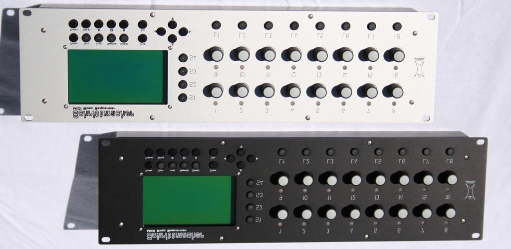
6 Operating elements & connections Front panel Display 2. Sequence buttons for selecting the active sequence range 3. Endless dial with LEDs to edit the 16 steps 4. Cursor buttons 5. Line buttons to select the active line 6. Power button 7. Sync, Loop and Step mode button 8. Global button 9. Enter and Escape 10. Preset and Setup menus 11. Start, Stop and Pause 4 Schrittmacher - Manual

7 Back panel 1. Voltage supply socket for the connection of the supplied power supply 2. LCD contrast 3. MIDI IN socket to receive MIDI data 4. MIDI OUT socket A to transmit MIDI data 5. MIDI OUT socket B to transmit MIDI data Schrittmacher - Manual 5
8 Introduction Even if you are a professional in using studio equipment and sequencers it will be useful to read this user manual right through to the end. The Schrittmacher features many new functions never before implemented in a hardware sequencer. About this manual This manual is intended to make the first steps for using the Schrittmacher easier for you. Moreover it also provides support and tips to the eperienced user for his daily work. For simplicity s sake all technical terms in these instructions are identical with the Schrittmacher s parameter designations. Symbols used To ensure a better overview, this manual uses standardized spelling and symbols which are eplained below. Important notes are highlighted in bold print.! Attention Pay special attention to this note to avoid malfunctions. i Gives some short additional information. Instructions Observe these instructions to eecute the requested function. Marking of parameters All designations of buttons, controllers and parameters of the Schrittmacher in the tet are highlighted in bold print. Eample: Press the Power button. The value range permitted for parameter setting is highlighted by indicating the maimum and minimum values in italics separated by three dots. Settings which cannot be represented by a value range are separated by a comma. Eample: Midi A01... A16, B01... B16 6 Schrittmacher - Manual
9 General safety notes Please read the safety notes below very carefully. They comprise some basic rules for the use of electric devices. Please read all the notes before you start using the device. Suitable location Only operate the device in closed rooms. Never operate the device in humid environments such as bathrooms, washing rooms or swimming pools. Do not operate the device in etremely dusty or dirty environments. Ensure unhindered air supply to all sides of the device. Do not place the device in close proimity of heat sources such as radiators. Do not epose the device to direct sunlight. Do not epose the unit to heavy vibration. Mains connection Only use the supplied connection cable. If the supplied mains connector does not fit into your socket you should consult a qualified electrician. Disconnect the mains connector from the socket if you do not use the device for a longer period of time. Never touch the mains connector with wet hands. When disconnecting, always pull the connector and never the cable. Operation Never place any vessels containing liquids on top of the device. Ensure that the device cannot move during operation. Use a solid base or a suitable built-in rack (19 format). Ensure that no objects can get inside the device. Should this happen against all odds, switch the device off and disconnect it from the mains. Then contact a qualified supplier. Maintenance Do not open the device. Any repair or maintenance should be done by qualified personnel only. There are no parts inside the device that could be maintained by the user. You will also lose your right to claim warranty if you open the device. Only use a dry, smooth cloth or brush for cleaning the device. Do not use any alcohol, solvents or similar chemicals. They will damage the surfaces. Proper use This device is eclusively intended for creating and processing control signals according to the MIDI standard. Any other use is not permitted and will eclude any warranty claims towards Manikin Electronic. Schrittmacher - Manual 7
10 Setup Parts supplied Please check when unpacking if all parts are included. Should something be missing contact your specialist supplier immediately. The Schrittmacher is supplied with: Power supply with cable, this manual. We recommend to keep the original packaging for further transports. Installation Place the Schrittmacher on a clean, even base. Installation in a solid 19" rack is recommended. The required space for the height is 132mm which corresponds to 3U. The installation depth is 85mm. Connections You need a mains outlet and at least one sound generator with MIDI interface. i The Schrittmacher allows internal generation of transposing and other MIDI control commands. However, the fun factor in using the Schrittmacher for your work will be increased by at least 10000%, if a master keyboard whose MIDI controllers can be freely assigned is connected to the MIDI input. How to make the necessary connections: 1. Ensure that the Schrittmacher and your MIDI devices are switched off. 2. Connect the supplied mains cable to the mains connector into a suitable mains outlet. 3. Connect the MIDI outputs of the Schrittmacher to the MIDI inputs of the sound generator. 4. Connect the MIDI input (MIDI IN) of the Schrittmacher to the MIDI output of a master keyboard (not required). 5. Switch the Schrittmacher and your MIDI devices on. 6. Continue with the chapter Basic Operation on the net page. 8 Schrittmacher - Manual
11 Basic Operation Power ON For Power ON press the Power button. After being switched on the Schrittmacher needs a few seconds to initialize. Power OFF To switch the device off press the Power button and keep it pressed until the device is separated from the mains. The off-delay of appro. 5 seconds is to prevent unintentional switching off. Thus pressing the Power button briefly will not result in an unintended and possibly embarrassing stop during a live concert. Playing sequences By pressing the Start button the loaded preset is started. All active lines of the 4 sequence ranges will now create MIDI events which are sent via the MIDI outputs. A running preset can be stopped by pressing the Pause button with the preset not being reset. By pressing the Start button again playing of the preset will be continued starting from that point where it was stopped. Using the Stop button you will stop playing and reset the preset to the initial position. Input using the endless dials The endless dials used in the Schrittmacher do not have an end stop position as opposed to potentiometers. They also have a pushbutton. Depending on the assigned function, parameters can be input using the endless dials: Editing parameters By turning an endless dial clockwise, the respective value is incremented. By turning it counter-clockwise the respective value is decremented. By pressing the endless dial the mode of a step (play / mute / skip) can be changed. It depends on the set step mode between which modes you can change. For more information read the Step Mode section on page 24. Menu navigation You can mark a menu item using the endless dial 9. By turning it clockwise you move the marking downward. By turning it counterclockwise you move it upward. Alternatively you can also move the marking using the cursor buttons. You can select the menu item by pressing the endless dial or the Enter button. You eit the menu without making any selection by pressing the Esc button. i When an endless dial can be used for a selection function, the respective LED lights orange. Schrittmacher - Manual 9
12 Working with the Schrittmacher After Power ON an initialized preset with a note line is loaded. All other lines are OFF. In the display you see the line that has been selected, the preset name, the play mode, the speed, the values of the 16 steps as well as the line parameters. Selecting a line The Schrittmacher has 4 separated sequence ranges between which you can change using the Sequence buttons. In each range there are 8 lines between which can be changed using the Line buttons. Once you have selected a line by means of the Sequence and Line buttons you can process the 16 steps and the line parameters of this line using the endless dials. The LEDs integrated in the Sequence and Line buttons indicate which line has been selected for editing. Alternatively there is an indication on the top left which line has been selected: for eample, S2 L3 means that you are editing the third line in the second sequence range. Editing a line Using the 16 endless dials allows you to edit the steps of the selected line. Editing the step values The value of a step is incremented by turning the endless dial clockwise. This means that the value is decremented if the endless dial is turned counter-clockwise. To cross very large value ranges some acceleration has been integrated i.e. the faster the endless dial is turned, the more values are skipped. Editing the step modes The mode of a step (play, mute/hold, skip) is indicated by a bi-colored LED above the endless dial: green the step is played red the step is set to mute or holds the last value off the step is skipped Switching from one step mode to another is ensured by pressing the respective endless dial. When pressing the Step mode button you select changeover between play and mute or play and skip. The step mode is indicated by the integrated LED: green changeover between play and mute/hold off changeover between play and skip The current step is lit while all other steps are dimmed. 10 Schrittmacher - Manual
13 Editing the line parameters To edit the line parameters you have to start by pressing the Enter button. The LEDs of the endless dials 1 and 9-12 will light in orange. Using the endless dial 1 allows you to set the speed irrespective of the selected line. The line parameters indicated in the lower third of the display can be edited using the endless dials More line parameters and editing aids (if available) can be displayed by pressing the cursor buttons. To eit this mode press the Enter or Esc button. Linking lines When you create a note line, all line parameters are initialized with constant values, i.e. all note values are sent with a constant velocity value Vel on the fied Midi channel Midi. To ensure that the lines sound more dynamic the velocity can be controlled by a Vel line, for eample. To do so create a Vel line in the same sequence range as the Note line.! Only lines in the same sequence range can be linked. Set all steps and line parameters of the Vel line as requested and return to the Note line. Set the Vel line you find following the constant value range (0-127) for the Vel line parameters. To do so turn the endless dial 10 beyond 127. All kinds of links are shown one after the other. i In principle it is possible to link one line with several other lines, i.e. a Vel line can control the velocity of several Note lines. You can either have an asynchronous (e.g. L2 ) or a synchronous (e.g. L2s ) link of the Vel line to the Note line. With an asynchronous link the current step of the Vel line is taken as velocity for the current step of the Note line. Since the parameters of each line can be set separately very comple sequence patterns can be created. This allows very lively but in some cases even almost unpredictable structures to be created. An eample: The Note line plays the first 3 steps (forward and with constant gate). The Vel line plays the first two steps (forward and with constant gate). The Note line gets the velocity from the Vel line asynchronously C-1 (100) C-2 (50) C-3 (100) C-1 (50) C-2 (100) C-3 (50) The created sequence of notes is repeated after 6 steps. Schrittmacher - Manual 11
14 With a synchronous link the parameters of the Vel line are completely ignored, only the values of the steps are required. Each step of the Note line is assigned the same step in the Vel line. An eample: The Note line plays the first 3 steps again (forward and with constant gate). The parameters of the Vel line are of no importance. The Note line gets the velocity from the Vel line synchronously C-1 (100) C-2 (50) C-3 (25) The sequence of notes created is repeated after 3 steps. i Do eperiment with the various possible links of the Schrittmacher and the available controlling means of your sound generator. You will come to very interesting results over and over again. 12 Schrittmacher - Manual
15 Line Parameters A substantial characteristic of the Schrittmacher is that each of the 32 lines available can be freely configured. This allows the Schrittmacher to be adapted to different ways of working and ensures work in many types of music. We refer you to the Editing the line parameters section on page 11 for further details. Type The Type line parameter allows you to set the function of a line. A line can generate note events, for eample or vary the velocity of another line or send MIDI controllers.! The Type line parameter can only be changed when the preset has been stopped. You can chose between the following types: Off For a better overall view we suggest you switch all lines you do not need to OFF. The steps of an OFF line cannot be edited. Note To be able to control a sound generator you need at least one Note line. The note events of this line are sent via the MIDI outputs. Using the steps you enter notes which are to be played. All 128 note values within the range from C-0 to G-10 which are defined by the MIDI standard can be set. i Define several note lines in one sequence range so that you can play polyphonic note sequences. Vel To vary the velocity of a Note line you can define a Vel line. Each step can be set to a value within the range from 0 up to 127. A velocity of 0 will not generate any note event since it is usually interpreted by the sound generator as NoteOff. Gate The Gate line allows you to vary the time intervals between the steps. The steps can be set within the range from 1/384 to 16 1/1 notes. For the table listing the values to be set we refer you to page 29. Len You can control the length of a note in a Note line by the Len line. The steps can be set within the range from 1/384 to 16 1/1 notes. For the table listing the values to be set we refer you to page 29. Schrittmacher - Manual 13
16 Midi You can play a note sequence alternately with different sounds by controlling the MIDI channel of a Note line with a Midi line. This way some kind of wave sequencing can be implemented. Using the steps of the Midi line you indicate the MIDI channels (and thus the sounds) on which is to be played. Settings from A01 to B16 are possible with the letter indicating the MIDI output and the number the MIDI channel. The MIDI channel of a Ctrl line can also be controlled by a Midi line. Add Using the Add line more offsets can be added to the values of the Note, Vel and Ctrl lines. This way a Note line can be transposed. By using an Add line the Vel and Ctrl lines can be additionally varied. Ctrl Besides the Note line, the Ctrl line is the only line which can output MIDI events on the MIDI outputs. Using the Ctrl line you can control the controllers and parameters of the sound generator. Using the steps you can set values in the rang from 0 to 127. We suggest you refer to the manual of your sound generator to see which parameters you can control by which controllers. Using the ID line parameter you can set the controller you want to use.! If you use a Ctrl line in conjunction with a Note line, make sure that the same MIDI channel is set in both lines. Mode The play mode of another line can be controlled by a Mode line. This way you can change the mode of another line while playing, e.g. from forward to random. Depending on the Type line parameter you have access to other line parameters such as play direction, MIDI channel, etc. Type Line Parameters Off Note Mode First Last Vel Mode First Last Gate Mode First Last Len Mode First Last Midi Mode First Last Add Mode First Last Ctrl Mode First Last Mode Mode First Last Sync Mode Sync Mode Sync Mode Sync Mode Sync Mode Sync Mode Sync Mode Sync Mode Sync Base Sync Base Sync Base Sync Base Sync Base Sync Base Sync Base Sync Base Gate Len Midi Vel Add Gate Add Gate Gate Gate Gate ID Midi Add Gate 14 Schrittmacher - Manual
17 Mode Using the Mode line parameter you set the play mode of a line. The following modes are possible: -> Forward <- Backward <-> Ping pong; the first and last steps are played once <=> Forward / backward; the first and last steps are played twice? Random The Mode line parameter can be linked with and controlled by a Mode line. First, Last First indicates the step of a line with which it starts. Last indicates the step with which the line ends. Set one value each from 1 to 16 for either line parameter to define these steps. If one of the steps is skipped, the line is automatically started or ended with the net step. Only those steps are played that are between First and Last. As an alternative, you can also define First and Last with the loop function. For more information about the loop function we refer you to the Loop section on page 24. Sync Mode, Sync Base With Sync Mode you can set automatic or manual synchronization of the line (by pressing the Sync button). Synchronization follows the time set in the Sync Base line parameter. For the table indicating the values to be set we refer you to page 29. For further information about synchronization we refer you to the Sync section on page 24. Gate The time interval between to consecutive steps is defined by the Gate line parameter. The interval can be set within the range from 1/384 to 16 1/1 notes. For the table indicating the values to be set we refer you to page 29. The Gate line parameter can be linked with and controlled by a Gate line. Len The Len line parameter can only be found for Note lines. Len determines the length of the notes played and can be set within the range from 1/384 to 16 1/1 notes. For the table indicating the values to be set we refer you to page 29. i Setting Len is limited by the Gate line parameter, i.e. a note is only held until a new note is struck. The Len line parameter can be linked with and controlled by a Len line, Key or Ctrl1-8. Schrittmacher - Manual 15
18 The Gate and Len line parameters influence the note output as follows: Gate sets the interval between two note-on events; Len defines the interval between a note-on and the respective note-off event. Figure 1 Effect of Gate and Len on the note output Midi The Midi line parameter defines the MIDI output and the MIDI channel for a Note or Ctrl line. You can set values from A01 to B16 with the letter indicating the MIDI output and the number the MIDI channel. The Midi line parameter can be linked with and controlled by a Midi line. Vel The velocity of a Note line can be set by the Vel line parameter within the range from 0 to 127. At a velocity of 0 no note event is generated because it is usually interpreted by sound generators as note off. The Vel line parameter can be linked with and controlled by a Vel line, Key or Ctrl1-8. Add Using Add an additional offset is added to the steps of the Note, Ctrl and Vel lines. Note lines can be transposed and Ctrl and Vel lines can be varied in their course. Add can only be linked with an Add line or a controller. A constant value cannot be set. To do so use the Add editing aid described on page 17. The Add line parameter can be linked with and controlled by an Add line, Key or Ctrl1-8. ID The ID line parameters can only be found with Ctrl lines. Using ID you can select the controller to be sent. The following settings are possible: Pitch the Ctrl line sends pitch bend events Ch.Aft. the Ctrl line sends channel aftertouch events the Ctrl line sends control changes with the set controller ID The ID line parameter cannot be linked with and controlled by any other lines.! If you edit the ID line parameter while playing the preset, it is possible that some settings of the connected sound generator are changed unintentionally. Therefore always edit ID in the stopped state. 16 Schrittmacher - Manual
19 Editing aids Following the line parameters there are the editing aids which are intended to simplify step processing. Here again inputs are made using the endless dials whose respective LEDs are lit in orange. Add Using Add you can increment or decrement all step values of a line at the same time. This means that you can transpose a Note line very quickly, for eample, without having to set each step individually. This function is also very useful if you play a single drum sound with a Note line. Using Add drum maps can be searched very conveniently. Rotate Using Rotate you shift all steps of a line to any position to the left or right. Since the step modes (play, mute/hold, skip) are not shifted, this function is also useful for live operation. And again: Try it out. Each eperiment will reap a reward! Schrittmacher - Manual 17
20 Setup Menu If the Schrittmacher is in the stop or pause mode, you get into the setup menu by pressing the Setup button. Mark the requested menu item by means of the cursor buttons and or the endless dial 9. By pressing the Enter button or the endless dial 9 you select the marked menu item. You eit the menu without making any selection by pressing the Esc button. The setup menu provides the following menu items: MIDI Settings The MIDI setup allows setting of some global settings referring to all 4 sequences of a preset. Here basic settings are made such as the MIDI receive channel or the type of clock source. MIDI MIDI indicates the MIDI channel via which the sequences can be changed (e.g. transposed) using the master keyboard. There is no reaction to notes and controller events of the other channels. So remember to set the MIDI output of your keyboard to this channel. i The Schrittmacher is not transparent for incoming MIDI events, i.e. all MIDI data received on MIDI IN will be filtered, ecept Timing Clock, Start, Stop and Continue! ID ID is the device number and serves to differentiate several Schrittmacher in one MIDI setup. Should you use several Schrittmacher, set a different ID for each device. If only one Schrittmacher is used, the basic setting (0) does not need to be changed.. 18 Schrittmacher - Manual
21 Clock Int, Et To ensure that all devices in a MIDI setup work synchronously to each other a MIDI clock has to be generated. The Schrittmacher can work with two different clock sources: Internal MIDI clock (Int): The Schrittmacher is the clock master in the MIDI setup, i.e. it generates Timing Clock, Start, Stop and Continue signals which are output on MIDI OUT A. The speed of the clock can be set using the BPM parameter. Eternal MIDI clock (Et): The Schrittmacher is the clock slave in the MIDI setup, i.e. another device (e.g. a PC) generates a MIDI clock. In this case the Schrittmacher is automatically synchronized with the eternal MIDI clock. The Timing Clock, Start, Stop and Continue signals generated by the clock master are output on MIDI OUT A. Using an eternal clock the Schrittmacher can be operated at a faster (or slower) speed than the speed possible by using the internal clock. i Internally the Schrittmacher always uses a resolution of 96 ppq (pulses per quarter note). This resolution is four times greater than the MIDI standard (24 ppq) and thus enables a considerably finer setting of the time-dependent line parameters (Gate, Len and Sync Base). Eternally the Schrittmacher uses the standard resolution of 24 ppq. This means that you can use the Schrittmacher also in conjunction with other MIDI sequencers without any problems. BPM This parameter is used to set the speed in BPM (beats per minute). Values from 10 to 250 BPM with a resolution of 1 BPM are possible. This setting can also be changed outside this setup namely when editing line parameters. Key Off, On If a keyboard is to be used to control the Schrittmacher this use can be activated in the setup. The keyboard range to be used is defined by the settings Low, Center and High. If Key is set to OFF these settings are of no significance. Low C-0... Center Low defines the lowest note of the requested keyboard range. The maimum possible value for Low is limited by Center. Center Low... High If the note defined by Center is pressed on the keyboard connected, Key provides a value of 0. Only a note value between the range of Low and High can be set for Center. High Center... G-10 High defines the uppermost note of the requested keyboard range. The minimum possible value for High is limited by Center. Schrittmacher - Manual 19
22 Ctrl1... Ctrl8 Int, Pitch, Ch.Aft, Controllers can be defined for global controlling. To do so a distinction is made between internal and eternal controllers. If an internal controller (INT) is defined it can only be controlled by the respective endless dial in the Global mode. To define an eternal controller Pitch, Ch.Aft. or a controller number within the range from 0 to 120 has to be set. An eternal controller cannot only be controlled in the Global mode but also by an eternal MIDI device. Besides entitling a controller by its number, a value range can be defined for each of the controllers. The Low parameter indicates the output value with left touch, the High parameter the output value with right touch. Information This menu item informs you about the currently installed software version. 20 Schrittmacher - Manual
23 Preset Menu The menu is called by pressing the Preset button when the Schrittmacher is in the Stop or Pause status. Mark the requested menu item by means of the cursor buttons and or the endless dial 9. By pressing the Enter button or the endless dial 9 you select the marked menu item. By pressing Esc you eit the menu without making any selection. The preset menu provides the following functions to manage the preset: Load Preset This function enables loading of a preset from the memory. Initialized presets (empty presets) are entered in the preset list as Initial Preset. To allow loading the requested preset has to be marked and selected in the preset list. There are two possible ways: 1. Mark the requested preset in the preset list. Using the cursor buttons and the marking can be shifted by one memory place using the cursor buttons and it can be shifted by ten memory places. The preset is selected by pressing the Enter button. 2. Mark the requested preset by turning the endless dial 9. Select the marked preset by pressing the endless dial. Schrittmacher - Manual 21
24 Save Preset The Save Preset function enables saving of a preset in one of the 30 memory places. Saving a preset is effected in two steps: i You can stop the saving process of a preset at any time by pressing the Esc button. 1. Mark the memory place into which the preset is to be saved using the cursor buttons or the endless dial 9. Select the memory place by pressing the Enter button or by pressing the endless dial Create the name of the preset by means of the characters indicated. Mark the requested characters using the cursor buttons or the endless dial 9. Adopt the character by pressing the Enter button or the endless dial 9. t To delete a character already entered select the arrow pointing left ( corner. The preset is saved when OK (bottom right) is selected. "!$#%&'(%*),+-. / i To save a preset quickly without any new name turn the endless dial 9 counterclockwise once and press it. In rare cases it is possible that the preset memory has to be reorganized during the saving process. However, this usually happens automatically and takes only a short time. During reorganization the Schrittmacher must never be switched off since otherwise all saved presets will in all probability get lost. 22 Schrittmacher - Manual
25 Init Preset The current preset can be initialized to have a defined starting point for the new sequences. When initializing a preset, all 4 sequences with all lines and steps as well as the MIDI settings are put into a defined status: Line Type Value Param Value Comments S1 L1 Note C-3 Mode -> all 16 steps on play Gate 1/16 -- Len 1/16 -- MIDI 1 -- Vel Add Off -- S1 L2...L8 Off S2 L1...L8 Off S3 L1...L8 Off S4 L1...L8 Off MIDI settings Midi 1 Key Off Ctrl1...Ctrl8 Int Dev. ID 0 Low C-3 Low 0 Clock Int. Center F-3 High 127 BPM 120 High H-3 Val 0 0 If you load a preset entitled Initial Preset you will likewise get a preset with the described settings. Dump Preset The Dump Preset function allows a saved preset to be transmitted to a computer. When you have selected this function you will see a preset list in which you select the preset to be transmitted. Selection is effected as described in the Load Preset section. You can record the preset by means of a MIDI program that can receive and save SysE messages. If you want to transmit the preset back to the Schrittmacher only the recorded SysE message has to be played. Ensure that there is an operational MIDI connection between the Schrittmacher and the computer. Schrittmacher - Manual 23
26 Other Functions Preload Preset The Schrittmacher allows loading of another preset while playing a sequence and starting it synchronously at the global Sync clock. This enables direct transition between two presets. To do so press the Preset button while a preset is being played. Selection of the preset to be loaded is effected in the same way as for the Load Preset function. If a parameter is preloaded, a double play symbol is indicated in the display. The preloaded preset is kept ready in the background and can be started by pressing the Start button. Sync Using the Sync button a line can be resynchronized. Synchronization means that the line is set back to the first playable step depending on a Sync clock. The Sync clock is given by the Sync Base line parameter and indicated by the lit Sync LED. When you have pressed the Sync button the Sync LED is displayed dimmed until the line has been synchronized. Besides this manual synchronization you can also set automatic synchronization by the Sync Mode line parameter. In this setting the Sync LED remains dimmed and the line is automatically reset with each Sync clock. i Lines with the play mode set to random cannot be synchronized. Not only individual lines can be synchronized but also the whole preset. To do so press the Sync button in the global mode. All lines are reset to the first step to be played. The global Sync clock is firmly set to 1/1 note. Loop In the Loop mode it is very easy for you to define a loop in your line. Press the Loop button to change into the Loop mode (the integrated LED is lit). Now you can define the first and the last steps of the loop alternately by pressing the endless dial. You eit the Loop mode by pressing the Loop button again (the integrated LED goes out). i While the Loop mode is activated the step modes (play, mute/hold, skip) cannot be changed. To do so eit the Loop mode. Steps which are not in the defined loop cannot be changed in the mode even if the Loop mode has been eited. Alternatively you can set the first and the last steps of a loop by using the First and Last line parameters. Step mode Using the Step mode button you can select if the mode of a step is changed between play and mute or play and skip. The step mode is indicated by the integrated LED: green changeover between play and mute/hold off changeover between play and skip It is possible for you to switch individual steps of a line to mute or to switch them off completely. 24 Schrittmacher - Manual
27 Global The Global mode enables controlling of a preset on a higher level and is of central importance when working with the Schrittmacher. In the display you cannot only see the information that the Global mode is activated but also the selected sequence range, the play mode, the speed, the modes of the 8 global controllers and the 8 lines of the selected sequence range. The modes of the 8 controllers of the Schrittmacher are shown in the upper half of the display as dials. They can be changed by means of the endless dials 1-8. Below the dials you can see the value generated for the respective controller. This part of the display is independent of the sequence range set. You can configure the functions and value ranges of the individual controllers in the setup. We suggest you read the MIDI Settings section on page 18. In the global mode individual lists of the selected sequence range can be switched on and off. Press a Line button to switch the respective line on (white field and black print) and off again (black field and white print) alternately. Change the sequence range by pressing the Sequence button to switch the other lines on and off. Schrittmacher - Manual 25
28 Updating the operating software The Schrittmacher provides a maintenance-friendly function to update the internal operating software without having to replace parts. A software update is available as a standard MIDI file which can be installed in the Schrittmacher using a sequencer software. You can download this file from our website: i You may possibly get a zipped file from our website which includes the new operating software as well as an updated user manual. If you have no access to the Internet you can get a floppy disk with the current software version from your supplier or directly from Manikin Electronic. The trade magazines also provide the current operating software on an attached CD-ROM at irregular intervals. How to update the Schrittmacher s operating software: Load the unzipped.mid file into your sequencer software. Ensure that all cycle or loop modes are deactivated. Switch the Schrittmacher on. Transmit the.mid file to the Schrittmacher by playing it. As soon as the Schrittmacher receives the operating software via MIDI you can see the software version and the progress of the file transfer in the display. Once the file has been completely transferred, the operating software transferred is installed. The installation progress can also be followed in the display.! Do not switch off the Schrittmacher while the operating software is being updated. This could cause a complete loss of data so that the Schrittmacher is no longer operational! 26 Schrittmacher - Manual
29 After successful update the Schrittmacher will start up automatically using the updated operating software. If the file transfer is aborted or if an error occurs, an error message is displayed. Press the Esc button and try again. It may be necessary to reduce the speed of your sequencer program. If other trials are not successful, either, download the file again from the Internet or ask for a new floppy disk to be on the safe side. Schrittmacher - Manual 27
30 Productsupport If you have any question about your Manikin Electronic-Product, please contact us. You have the coice between four possibilities: 1 Sent us a . support@manikin-electronic.com 2 Sent us a Telefa. +49 (0) Sent us a letter. Manikin Electronic Attilastraße 87k Berlin, Germany 4 If you have a urgent Question, call us. +49 (0) Schrittmacher - Manual
31 Anne Time and clock table The Schrittmacher works on an internal time resolution of 96 ppq (pulses per quarter note). The table below shows all values that can be set for the time-dependent parameters: Gate, Len and Sync Base /1 (1920) 10 1/1 (3840) 1/16T (16) 1/8T (32) 1/4T (64) 1/2T (128) 1/1T (256) 2 1/1T (512) 4 1/1T (1024) 8 1/1T (2048) 16 1/1T (4096) /32. (18) 1/16. (36) 1/8. (72) 1/4. (144) 1/2. (288) 1/1. (576) 3 1/1 (1152) 6 1/1 (2304) 12 1/1 (4608) 1/32T (8) /1 (2688) 14 1/1 (5376) /32 (12) 1/16 (24) 1/8 (48) 1/4 (96) 1/2 (192) 1/1 (384) 2 1/1 (768) 4 1/1 (1536) 8 1/1 (3072) 16 1/1 (6144) Schrittmacher - Manual 29
32 Technical data Voltage supply Nominal voltage : AC 110V-230V / 50Hz-60Hz (auto-switching supply) Maimum current consumption : 0.8A Maimum power consumption : 7.2W MIDI Connections : MIDI IN, 2 MIDI OUT Dimensions and weight Dimensions (width/height/depth) : 482mm 132mm (3U) 85mm 19 5,2 3,3 Overall weight : 2.5 kg 30 Schrittmacher - Manual
33 CE This product has been tested and found to comply with the following Harmonised European Standards: EN 55013: 2003, CENELEC EN 55020: 2003, EN : 2000 and EN : corr FCC Information (U.S.A.) 1. IMPORTANT NOTICE: DO NOT MODIFY THIS UNIT! This product, when installed as indicated in the instructions contained in this Manual, meets FCC requirements. Modifications not epressly approved by Manikin Electronic may void your authority, granted by the FCC, to use this product. 2. IMPORTANT: When connecting this product to accessories and/or another product use only high quality shielded cables. Cable/s supplied with this product MUST be used. Follow all installation instructions. Failure to follow instructions could void your FCC authorisation to use this product in the USA. 3. NOTE: This product has been tested and found to comply with the requirements listed in FCC Regulations, Part 15 for Class B digital devices. Compliance with these requirements provides a reasonable level of assurance that your use of this product in residential environment will not result in harmful interference with other electronic devices. This equipment generates/uses radio frequencies and, if not installed and used according to the instructions found in the users manual, may cause interference harmful to the operation of other electronic devices. Compliance with FCC regulations does not guarantee that interference will not occur in all installations. If this product is found to be the source of interference, which can be determinated by turning the unit OFF and ON, please try to eliminate the problem by using one of the following measures: Relocate either this product or the device that is being affected by the interference. Utilise power outlets that are on branch (Circuit breaker or fuse) circuits or install AC line filter/s. In the case of radio or TV interference, relocate/reorient the antenna. If the antenna lead-in is 300 ohm ribbon lead, change the lead-in to coaial type cable. If these corrective measures do not produce satisfactory results, please contact the local retailer authorised to distributed this type of product. The statements above apply ONLY to products distributed in the USA. Canada The digital section of this apparatus does not eceed the Class B limits for radio noise emissions from digital apparatus set out in the radio interference regulation of the Canadian Department of Communications. Le present appareil numerique n emet pas de briut radioelectri-ques depassant les limites aplicables au appareils numeriques de la Classe B prescrites dans la reglement sur le brouillage radioelectrique edicte par le Ministre Des Communications du Canada. Ceci ne s applique qu au produits distribués dans Canada. Other Standards (Rest of World) This product complies with the radio frequency interference requirements of the Council Directive 89/336/EC. Cet appareil est conforme au prescriptions de la directive communautaire 89/336/EC. Dette apparat overholder det gaeldenda EF-direktiv vedrørendareadiostøj. Dieses Gerät entspricht der EG-Richtlinie 89/336/EC. Schrittmacher - Manual 31
34 MIDI implementation chart Model: Schrittmacher Midi implementation chart Date: 01 Feb Version: 1.0a Function... Transmitted Recognized Remarks Basic Default Channel Changed Default Mode Massages Altered ********** Note Number True Voice ********** Velocity Note ON Note OFF o 9n, v= n, v=0 o 9n, v=1-127 After Keys Touch Ch s o o Pitch Bender o o 7-bit resolution Control Change o o Prog Change : True ********** System Eclusive o o System : Song Pos : Song Sel Common : Tune System : Clock o o Real Time : Commands o o Au : Local ON/OFF : All Notes OFF Massages : Active Sense : Reset MIDI Clock Start, Stop, Continue Notes Mode 1: OMNI ON, POLY Mode 2: OMNI ON, MONO o: yes Mode 3: OMNI OFF, POLY Mode 4: OMNI OFF, MONO : no 32 Schrittmacher - Manual
35 Glossary Aftertouch Most modern MIDI keyboards can generate Aftertouch messages. If you press down on a key while it is already playing on such a keyboard, this aftertouch generates MIDI messages. This can be used to add an epressive volume swell to the sound character (e.g. vibrato). Control Change (Controllers) Using these MIDI messages it becomes possible to change the sound response of the sound generator. This message basically consists of two parts: the controller number which determines what is influenced. It can range between 0 and 120, the controller value which determines the intensity of the modification. Eamples of the use of controllers are slowly starting vibrato, movement of the sound in panorama position or influence on the filter frequency. Gate In the field of sound technology the term gate is used in several contets. The literal meaning shows you the basic feature of this term: It can be open or closed or, technically speaking, active or inactive. A gate in the sense of a device is a module which allows a signal to pass or which blocks it, depending on certain marginal conditions. For eample, this is used in a noise gate so that only signals with a defined minimum level are allowed to pass to suppress the noise in signal pauses. In the contet of analog synthesizers gate is seen as a control signal which can be in either the active or the inactive mode. An eample is the keyboard of such a synthesizer. When you press a key, it provides two separate signals: CV and gate. The gate signal is active as long as the key is pressed, then it becomes inactive at once. In sound generation this gate signal may lead to triggering an envelope which controls the VCA. MIDI MIDI is short for Musical Instrument Digital Interface. It was developed in the early eighties to link electronic musical instruments of different types and from different manufacturers. Up to that time there was no standard for linking several sound generators and so MIDI was a considerable improvement. From then on it became possible to link all devices using easy and always identical connection cables. The basic steps are: A transmitter is always connected with one or several receivers. If, for eample, a computer is to play a synthesizer the computer is the transmitter and the synthesizer the receiver. For this purpose all MIDI devices (with only a few eceptions) have two or three connections: MIDI IN, MIDI OUT and possibly MIDI THRU. The transmitting device provides the information to the outside world via its MIDI OUT connection. The data are passed on to the MIDI IN connection of the receiver by means of a cable. The MIDI THRU connection has a special meaning. It makes it possible for a transmitter to reach several receivers. It works in such a way that it provides the incoming signal without any changes. Another receiving device is then simply plugged into the MIDI THRU connector. This process creates a chain in which one transmitter and several receivers are connected. It is, of course, a requested feature that the transmitter can control each individual device separately. Therefore it has to be ensured that the individual devices keep to certain rules among each other. MIDI Channel An important part of most messages. A receiving device only reacts to incoming messages if its set receiving channel is identical with the transmitting channel of the message. This makes clear information transfer to a receiver possible. The MIDI channel can be selected within the range from 1 to 16. Beyond this range a device can be switched to Omni. Then it will receive on all 16 channels. MIDI Clock The time interval of the MIDI Clock message defines the tempo of a musical piece. It is used for synchronizing time-dependent processes. Schrittmacher - Manual 33
36 Note on / note off This is the most important MIDI message. It determines the tone pitch and the velocity of the tone generated. The time of its arrival is at the same time the starting point of the tone. The pitch is the result of the transmitted note numbers. It is within the range from 0 to 127. The velocity is within the range from 1 to 127. The value 0 for the velocity means NoteOff, i.e. the note is switched off. Panning Designates the panorama position of a sound. Pitch Bend Pitch Bend is a MIDI message. Although the functions of the Pitch Bend message are similar to those of the control change messages, it represents a message type of its own. The reason why is above all that the Pitch Bend message is transmitted with a considerably finer resolution than the usual controller. This takes into account that the human ear is etremely sensitive to pitch changes. Program Change MIDI messages for selecting the sound program. It is possible to select between the program numbers 1 to 128. System Eclusive data System Eclusive data represent the access to the innermost part of a MIDI device. They enable access to data and functions which are not represented by any other MIDI messages. Eclusive also means that the data indicated here only apply to one single type of device. Each device has its own System Eclusive data. The most frequent applications for this data type are the transmission of complete memory contents as well as the complete device control by means of a computer. Trigger A trigger is a triggering signal for events. The nature of the trigger signal can vary considerably. A MIDI note or an audio signal can act as a trigger, for eample. The event triggered can also vary considerably. A frequently used application is triggering an envelope. 34 Schrittmacher - Manual
FCC Compliance Statement
 FCC Compliance Statement This device complies with part 15 of the FCC Rules. Operation is subject to the following two conditions: 1. This device may not cause harmful interference, and 2. This device
USER MANUAL. 27 Full HD Widescreen LED Monitor L27ADS
 USER MANUAL 27 Full HD Widescreen LED Monitor L27ADS TABLE OF CONTENTS 1 Getting Started 2 Control Panel/ Back Panel 3 On Screen Display 4 Technical Specs 5 Care & Maintenance 6 Troubleshooting 7 Safety
USER MANUAL. 27 Full HD Widescreen LED Monitor L270E
 USER MANUAL 27 Full HD Widescreen LED Monitor L270E TABLE OF CONTENTS 1 Getting Started 2 Control Panel/ Back Panel 3 On Screen Display 4 Technical Specs 5 Care & Maintenance 6 Troubleshooting 7 Safety
English. Analog LCD Monitor. AL502 User s Manual
 Analog LCD Monitor AL502 User s Manual TABLE OF CONTENTS FCC compliance statement... 1 DOC compliance notice... 1 Introduction... 2 Features... 2 Unpacking... 3 Screen position adjustment... 4 Connecting
USER MANUAL. 27" 2K QHD LED Monitor L27HAS2K
 USER MANUAL 27" 2K QHD LED Monitor L27HAS2K TABLE OF CONTENTS 1 Getting Started 2 Control Panel/ Back Panel 3 On Screen Display 4 Technical Specs 5 Troubleshooting 6 Safety Info & FCC warning 1 GETTING
Scoreboard Operator s Instructions MPCX SCD / DGT / Pitch Time Control
 Scoreboard Operator s Instructions MPCX SCD / DGT / Pitch Time Control Since 1934 Retain this manual in your permanent files Rev. 2/3/2012 135-0136 These Instructions are for the Following Models: LED
MONOPRICE. 27" UHD IPS 4K Ultra Slim Aluminum Monitor. Quick User's Guide P/N 24658
 MONOPRICE 27" UHD IPS 4K Ultra Slim Aluminum Monitor P/N 24658 Quick User's Guide SAFETY WARNINGS AND GUIDELINES Please read this entire manual before using this device, paying extra attention to these
USER MANUAL Full HD Widescreen LED Monitor L215IPS
 USER MANUAL 21.5 Full HD Widescreen LED Monitor L215IPS TABLE OF CONTENTS 1 Getting Started 2 Control Panel/ Back Panel 3 On Screen Display 4 Technical Specs 5 Care & Maintenance 6 Troubleshooting 7 Safety
USER MANUAL. 28" 4K Ultra HD Monitor L28TN4K
 USER MANUAL 28" 4K Ultra HD Monitor L28TN4K TABLE OF CONTENTS 1 Getting Started 2 Control Panel/ Back Panel 3 On Screen Display 4 Technical Specs 5 Care & Maintenance 6 Troubleshooting 7 Safety Info &
Scoreboard Operator s Instructions MPCX Volleyball Control
 Scoreboard Operator s Instructions MPCX Volleyball Control Since 1934 Retain this manual in your permanent files Rev. 2/3/2012 135-0137 These Instructions are for the Following Models: LED models: Incandescent
Start/Stop works in each mode, and puts the pattern back to the starting point step 1 of the current pattern.
 Sequencer Modes In all six modes the playing of the sequencer is guaranteed. You can change the modes, while the sequencer is running. Switching into another mode, takes place after the last step of the
SAFETY WARNINGS AND GUIDELINES INTRODUCTION CUSTOMER SERVICE
 SAFETY WARNINGS AND GUIDELINES Prior to operation, check the unit and power cord for physical damage. Do not use if physical damage has occurred. Before plugging the unit into a power outlet, ensure that
MONOPRICE. BitPath AV VGA Extender over Single Cat6 Cable, 120m. User's Manual P/N 16226
 MONOPRICE BitPath AV VGA Extender over Single Cat6 Cable, 120m P/N 16226 User's Manual SAFETY WARNINGS AND GUIDELINES Please read this entire manual before using this device, paying extra attention to
DCL9AW. User Manual. English
 DCL9AW User Manual English PRECAUTIONS Information for users applicable in European Union countries 1 Information for users applicable in United States of America 1 Installation 1 Power connection 1 Maintenance
USER S MANUAL
 612720 USER S MANUAL SAFETY WARNINGS AND GUIDELINES Prior to operation, check the unit and power cord for physical damage. Do not use if physical damage has occurred. Before plugging the unit into a power
USER MANUAL Full HD Widescreen LED Monitor L215ADS
 USER MANUAL 21.5 Full HD Widescreen LED Monitor L215ADS TABLE OF CONTENTS 1 Getting Started 2 Control Panel/ Back Panel 3 On Screen Display 4 Technical Specs 5 Care & Maintenance 6 Troubleshooting 7 Safety
Spectra Batten (Order code: LEDJ95)
") www.prolight.co.uk Spectra Batten (Order code: LEDJ95) Safety WARNING FOR YOUR OWN SAFETY, PLEASE READ THIS USER MANUAL CAREFULLY BEFORE YOUR INITIAL START-UP! CAUTION! Keep this equipment away from rain,
www.prolight.co.uk Spectra Batten (Order code: LEDJ95) Safety WARNING FOR YOUR OWN SAFETY, PLEASE READ THIS USER MANUAL CAREFULLY BEFORE YOUR INITIAL START-UP! CAUTION! Keep this equipment away from rain,
DV6819 Quick Reference Guide V1.0. Smart TV Box. Quick Reference Guide. Please do read user manual before you operate the TV box.
 DV6819 Quick Reference Guide V1.0 Smart TV Box Quick Reference Guide Please do read user manual before you operate the TV box. ~ 1 ~ DV6819 Quick Reference Guide V1.0 Safety instruction Please keep the
2.0 Wall Mount TV Soundbar Instruction Manual
 8010275 2.0 Wall Mount TV Soundbar Instruction Manual Read all of the instructions before using this soundbar and keep the manual in a safe place for future reference. Safety Information CA UT IO N RISK
FXL8 Pro effects looper. user manual
 FXL8 Pro effects looper user manual Musikhaus Thomann e.k. Treppendorf 30 96138 Burgebrach Germany Telephone: +49 (0) 9546 9223-0 E-mail: info@thomann.de Internet: www.thomann.de 15.09.2014, ID: 337603
TRANSCENSION 6-CHANNEL DMX DIMMER PACK (order code: BOTE40) USER MANUAL
 USER MANUAL") www.prolight.co.uk TRANSCENSION 6-CHANNEL PACK (order code: BOTE40) USER MANUAL SAFETY WARNING FOR YOUR OWN SAFETY, PLEASE READ THIS USER MANUAL CAREFULLY BEFORE YOUR INITIAL START-UP! CAUTION! Keep this
www.prolight.co.uk TRANSCENSION 6-CHANNEL PACK (order code: BOTE40) USER MANUAL SAFETY WARNING FOR YOUR OWN SAFETY, PLEASE READ THIS USER MANUAL CAREFULLY BEFORE YOUR INITIAL START-UP! CAUTION! Keep this
MONOPRICE. BitPath AV 4K 1X4 HDMI Splitter Extender over Single Cat6 with IR, 120m. User's Manual P/N 16286
 MONOPRICE BitPath AV 4K 1X4 HDMI Splitter Extender over Single Cat6 with IR, 120m P/N 16286 User's Manual SAFETY WARNINGS AND GUIDELINES Please read this entire manual before using this device, paying
ASH - EOC-01. Ethernet Over Coax Adapter User Guide
 ASH - EOC-01 Ethernet Over Coax Adapter User Guide ASH - EOC-01 User s Guide 1 Table of Contents Warning and Safety Information 3 Product Overview 8 Package Contents and Accessories 8 Introduction 9 Indicators
MONOPRICE. BitPath AV HDMI Extender over Single Cat6 Cable, 120m. User's Manual P/N 16228
 MONOPRICE BitPath AV HDMI Extender over Single Cat6 Cable, 120m P/N 16228 User's Manual SAFETY WARNINGS AND GUIDELINES Please read this entire manual before using this device, paying extra attention to
USER MANUAL. 22" Class Slim HD Widescreen Monitor L215DS
 USER MANUAL 22" Class Slim HD Widescreen Monitor L215DS TABLE OF CONTENTS 1 Getting Started Package Includes Installation 2 Control Panel / Back Panel Control Panel Back Panel 3 On Screen Display 4 Technical
MONOPRICE. Blackbird 4K HDMI Extender. User's Manual P/N 24281
 MONOPRICE Blackbird 4K HDMI Extender P/N 24281 User's Manual SAFETY WARNINGS AND GUIDELINES Please read this entire manual before using this device, paying extra attention to these safety warnings and
MONOPRICE. Blackbird 4K Pro HDBaseT Extender Kit. User's Manual P/N 21609
 MONOPRICE Blackbird 4K Pro HDBaseT Extender Kit P/N 21609 User's Manual SAFETY WARNINGS AND GUIDELINES Please read this entire manual before using this device, paying extra attention to these safety warnings
USER MANUAL Full HD Widescreen LED Monitor L236VA
 USER MANUAL 23.6 Full HD Widescreen LED Monitor L236VA TABLE OF CONTENTS 1 Getting Started 2 Control Panel/ Back Panel 3 On Screen Display 4 Technical Specs 5 Care & Maintenance 6 Troubleshooting 7 Safety
X20G-NagaIII. User s Manual
 X20G-NagaIII User s Manual FCC Compliance Statement This device complies with part 15 of the FCC Rules. Operation is subject to the following two conditions: 1. This device may not cause harmful interference,
PLL2210MW LED Monitor
 PLL2210MW LED Monitor USER'S GUIDE www.planar.com Content Operation Instructions...1 Safety Precautions...2 First Setup...3 Front View of the Product...4 Rear View of the Product...5 Quick Installation...6
Copyright Black Box Corporation. All rights reserved.
 Copyright 2003. Black Box Corporation. All rights reserved. 1000 Park Drive Lawrence, PA 15055-1018 724-746-5500 Fax 724-746-0746 SOHO 6-Port CAT5e 568B Data Module SEPTEMBER 2003 JPM1101A CUSTOMER SUPPORT
PXL2760MW LED LCD Monitor
 PXL2760MW LED LCD Monitor USER'S GUIDE www.planar.com Content Operation Instructions...1 Safety Precautions...2 Package Overview...3 First Setup...4 Front View of the Product...5 Rear View of the Product...6
To ensure long, trouble-free operation, please read this manual carefully. Precautions
 Thank you purchasing the Korg ELECTRIBE M EM-1. In order to enjoy long and trouble-free use, please read this manual carefully and use the instrument correctly. E 1 To ensure long, trouble-free operation,
MONOPRICE. BitPath AV SDI Extender over Single Cat6 Cable, 120m. User's Manual P/N 16227
 MONOPRICE BitPath AV SDI Extender over Single Cat6 Cable, 120m P/N 16227 User's Manual SAFETY WARNINGS AND GUIDELINES Please read this entire manual before using this device, paying extra attention to
Controller DMX DC-1224
 Manual Controller DMX DC-1224 Table of Contents 1. Safety instructions... 4 1.1. FOR SAFE AND EFFICIENT OPERATION... 4 3. Overview... 6 3.1. Front view... 6 3.2. Rear view... 9 4. Operation guide... 10
OPERATING MANUAL. DMX512 to DALI Dekoder 7044A-H Mk4
 last edited: 2014-08-12 OPERATING MANUAL DMX512 to DALI Dekoder 7044A-H Mk4 (C) SOUNDLIGHT 1996-2015 * ALL RIGHTS RESERVED * NO PART OF THIS MANUAL MAY BE REPRODUCED, DUPLICATED OR USED COMMERCIALLY WITHOUT
SAFETY WARNINGS AND GUIDELINES INTRODUCTION CUSTOMER SERVICE
 SAFETY WARNINGS AND GUIDELINES Prior to operation, check the unit and power cord for physical damage. Do not use if physical damage has occurred. Before plugging the unit into a power outlet, ensure that
19 / 20.1 / 22 WIDE SCREEN TFT-LCD MONITOR
 19 / 20.1 / 22 WIDE SCREEN TFT-LCD MONITOR V193/ V220 Series V202 Series USER MANUAL www.viewera.com Rev. 2.0 Table of Contents EMC Compliance......1 Important Precautions...2 1. Package contents....3
X-Series Expansion Cards. X-Video Card
 X-Series Expansion Cards X-Video Card User s Guide v1.0 - February 2006 Warnings FCC warning This equipment has been tested and found to comply with the limits for a Class A digital device, pursuant to
2.4GHz Digital Wireless Video Door Phone User Manual
 2.4GHz Digital Wireless Video Door Phone User Manual Thank you for purchasing our product. For better taking advantage of the prior functions please carefully read user manual for correct installation
Sync Genlock JULY 1993 AC083A. Sync Genlock
 JULY 1993 AC083A Sync Genlock Sync Genlock SC H PHASE SC 0 SC 180 SLOW LOCK FAST LOCK DISABLE ENABLE ENABLE POWER BURST CUSTOMER SUPPORT INFORMATION Order toll-free in the U.S. 24 hours, 7 A.M. Monday
2. only. INTRODUCTION...3. Do SPECIFICATION...3 SYSTEM SETTINGS...7. Installation. Troubleshooting. OVERVIEW Important Information
 www.switronix.com Troubleshooting Installation Important Information Read Step1: REC this user s REC X5TX manual X5TX carefully before transmitter: use. It contains important information notes regarding
PLL1920M LED LCD Monitor
 PLL1920M LED LCD Monitor USER'S GUIDE www.planar.com Content Operation Instructions...1 Safety Precautions...2 First Setup...3 Front View of the Product...4 Rear View of the Product...5 Installation...6
DDW36C Advanced Wireless Gateway - Safety and Installation Product Insert. Federal Communications Commission (FCC) Interference Statement
 Interference Statement") DDW36C Advanced Wireless Gateway - Safety and Installation Product Insert Federal Communications Commission (FCC) Interference Statement This equipment has been tested and found to comply with the limits
DDW36C Advanced Wireless Gateway - Safety and Installation Product Insert Federal Communications Commission (FCC) Interference Statement This equipment has been tested and found to comply with the limits
OWNER'S MANUAL CONTENTS. Identification of Controls and Terminals...4
 CONTENTS Identification of Controls and Terminals...4 Basic Operation... 6 1. Preparation and Basic Connections...6 2. Play Mode...8 3. Program Editing...12 The Four Modes and Their Functions... 15 Play
MONOPRICE. Blackbird 4K HDBaseT Extender Kit. User's Manual P/N 21792
 MONOPRICE Blackbird 4K HDBaseT Extender Kit P/N 21792 User's Manual SAFETY WARNINGS AND GUIDELINES Please read this entire manual before using this device, paying extra attention to these safety warnings
AUTO - SCANNING WITH DIGITAL CONTROL LCD COLOR MONITOR FS-L1903C. User manual (Rev.01) SMITHS HEIMANN
 SMITHS HEIMANN") AUTO - SCANNING WITH DIGITAL CONTROL LCD COLOR MONITOR FS-L1903C User manual (Rev.01) SMITHS HEIMANN www.smithsdetection.com Table of Contents Safety Instructions... 5 Accessories... 8 Power Connections...
AUTO - SCANNING WITH DIGITAL CONTROL LCD COLOR MONITOR FS-L1903C User manual (Rev.01) SMITHS HEIMANN www.smithsdetection.com Table of Contents Safety Instructions... 5 Accessories... 8 Power Connections...
LCD VALUE SERIES (32 inches)
") LCD VALUE SERIES (32 inches) http://www.orionimages.com All contents of this document may change without prior notice, and actual product appearance may differ from that depicted herein 1. SAFETY INSTRUCTION
LCD VALUE SERIES (32 inches) http://www.orionimages.com All contents of this document may change without prior notice, and actual product appearance may differ from that depicted herein 1. SAFETY INSTRUCTION
Table of Contents. APPENDIX A...12 TFT LCD Monitor Specifications 12. APPENDIX B...13 APPENDIX C...14 Troubleshooting Procedures 14 PREFACE...
 Table of Contents CHAPTER 1...1 Unpacking 1 Identifying Components 2 The LCD Monitor Front View 2 The LCD Monitor Rear View 3 Adjusting the Tilting Angle 3 Raising Your Monitor to an Upright Position and
PREFACE. About this manual. FCC Compliance Statement
 PT1503NT PREFACE About this manual This manual is designed to assist you in setting up and using your New Planar LCD Monitor. Information in this document has been carefully checked for accuracy; however,
Satellite Radio. Expand Your Factory Radio ISSR bit & 29-bit LAN. Owner s Manual Gateway. add. Harness Connection USB. Port 1 Port.
 Expand Your Factory Radio Harness Connection add Satellite Radio Dip Switches Port 1 Port 2 (See Manual) USB GM 11-bit & 29-bit LAN Owner s Manual Gateway ISSR12 Table of Contents 1. Introduction 2. Precautions
DMS-6 DUAL REDUNDANT WORD CLOCK DISTRIBUTION AMPLIFIER CONTENTS
 DRAWMER D-Clock-R DMS-6 DUAL REDUNDANT WORD CLOCK DISTRIBUTION AMPLIFIER CONTENTS Warranty........................................................... 2 Safety Consideration.................................................
TV Connector user guide
 TV Connector user guide Thank you Thank you for choosing the TV Connector. The intended use of the TV Connector is to connect your hearing aids directly to your TV or audio source. Your TV Connector Hearing
2-Port Hub Type 1 2-Port Hub Type 3 Unshielded 2-Port Hub Type 3 Shielded
 Type 1 Type 3 Unshielded Type 3 Shielded SEPTEMBER 1994 LT7000A LT7001A LT7002A 1 2 R I N G Type 1 R I N G 1 2 Type 3 R I N G 1 2 Type 3 CUSTOMER SUPPORT INFORMATION Order toll-free in the U.S. 24 hours,
CINEGEARS MULTI AXIS FOLLOW FOCUS KIT V3 MANUAL BOOK Cine Gears INC. All Rights Reserved.
 CINEGEARS MULTI AXIS FOLLOW FOCUS KIT V3 MANUAL BOOK Statement of Conditions In the interest of improving internal design, operational function, and/or reliability, Cine Gears Inc. reserves the right to
QUAD LFO MANUAL V SE 14TH AVENUE PORTLAND OR USA
 www.malekkoheavyindustry.com 814 SE 14TH AVENUE PORTLAND OR 97214 USA TABLE OF CONTENTS SPECIFICATIONS 1 INSTALLATION 2 DESCRIPTION 3 CONTROLS 4-6 USING QUAD LFO WITH VARIGATE 8+ AND VARIGATE 4+ 7 WARRANTY
CAUTION RISK OF ELECTRIC SHOCK NO NOT OPEN
 Evolution Digital HD Set-Top Box Important Safety Instructions 1. Read these instructions. 2. Keep these instructions. 3. Heed all warnings. 4. Follow all instructions. 5. Do not use this apparatus near
2.4 GHz WIRELESS SURVEILLANCE SYSTEM
 2.4 GHz WIRELESS SURVEILLANCE SYSTEM Operating Instructions Tested Comply With FCC Standards Model # TBM-18 BEFORE OPERATING THIS PRODUCT, READ, UNDERSTAND, AND FOLLOW THESE INSTRUCTIONS. Be sure to save
TV Connector user guide
 TV Connector user guide Thank you Thank you for choosing the TV Connector. The intended use of the TV Connector is to connect your hearing aids directly to your TV or audio source. Your TV Connector Hearing
HD Digital MPEG2 Encoder / QAM Modulator
 HD Digital MPEG2 Encoder / QAM Modulator YPrPb VGA In QAM Out series Get Going Guide ZvPro 600 Series is a one or two-channel Component or VGA-to-QAM MPEG 2 Encoder/ Modulator, all in a compact package
Dr. Strangelove synthblock
 Dr. Strangelove synthblock by Analogue Solutions Introduction SynthBlocks are a range of small desk top signal processors. No menus and no software. Just hardware. Typically all analogue, but with some
User Manual MODEL: KKF1500-PCAP. True FLAT P-CAP LCD Monitor. Installation Guide. 15 True FLAT P-CAP Touch LCD Monitor
 True FLAT P-CAP LCD Monitor User Manual Installation Guide 15 True FLAT P-CAP Touch LCD Monitor MODEL: KKF1500-PCAP i-tech Company LLC TOLL FREE: (888) 483-2418 EMAIL: info@itechlcd.com WEB: www.itechlcd.com
HD Digital MPEG2 Encoder / QAM Modulator
 HD Digital MPEG2 Encoder / QAM Modulator HDMI In QAM Out series Get Going Guide ZvPro 800 Series is a one or two-channel unencrypted HDMI-to-QAM MPEG 2 Encoder / QAM Modulator, all in a compact package
Industriefunkuhren. Technical Manual. IRIG-B Generator-Module for analogue / digital Signals of Type: IRIG-B / IEEE C / AFNOR NF S87-500
 Industriefunkuhren Technical Manual IRIG-B Generator-Module for analogue / digital Signals of Type: IRIG-B / IEEE C37.118 / AFNOR NF S87-500 Module 7628 ENGLISH Version: 02.01-06.03.2013 2 / 20 7628 IRIG-B
PL2410W LCD Monitor USER'S GUIDE.
 PL2410W LCD Monitor USER'S GUIDE www.planar.com Content Operation Instructions...1 Safety Precautions...2 First Setup...3 Front View of the Product...4 Rear View of the Product...5 Quick Installation...6
17 19 PROFESSIONAL LCD COLOUR MONITOR ART
 17 19 PROFESSIONAL LCD COLOUR MONITOR ART. 41657-41659 Via Don Arrigoni, 5 24020 Rovetta S. Lorenzo (Bergamo) http://www.comelit.eu e-mail:export.department@comelit.it WARNING: TO REDUCE THE RISK OF FIRE
Installation. Step 1 Carefully unpack the package contents.
 Installation Important: Please follow the installation procedure below. Improper operation may result if the start-up sequence is not correctly followed. Step 1 Carefully unpack the package contents. Step
PXL2470MW LED LCD Monitor
 PXL2470MW LED LCD Monitor USER'S GUIDE www.planar.com Content Operation Instructions...1 Unpacking Instructions...2 Safety Precautions...2 Package Overview...3 First Setup...4 Front View of the Product...5
APS W 12 inch. APS W 15 inch. 2 Way Active PA System with 3 Channel Mixer. 2 Way Active PA System with 3 Channel Mixer.
 P/N 604212 APS 12 400W 12 inch 2 Way Active PA System with 3 Channel Mixer P/N 604215 APS 15 400W 15 inch 2 Way Active PA System with 3 Channel Mixer User's Manual SAFETY WARNINGS AND GUIDELINES Do not
American DJ. Show Designer. Software Revision 2.08
 American DJ Show Designer Software Revision 2.08 American DJ 4295 Charter Street Los Angeles, CA 90058 USA E-mail: support@ameriandj.com Web: www.americandj.com OVERVIEW Show Designer is a new lighting
Evolution Digital HD Set-Top Box Important Safety Instructions
 Evolution Digital HD Set-Top Box Important Safety Instructions 1. Read these instructions. 2. Keep these instructions. 3. Heed all warnings. 4. Follow all instructions. 5. Do not use this apparatus near
Commander 384. w w w. p r o l i g h t. c o. u k U S E R M A N U A L
 Commander 384 w w w. p r o l i g h t. c o. u k U S E R M A N U A L 1, Before you begin 1.1: Safety warnings...2 3 1.2: What is included...4 1.3: Unpacking instructions...4 2, Introduction 2.1: Features...4
22" Touchscreen LED Monitor USER'S GUIDE
 22" Touchscreen LED Monitor USER'S GUIDE Content Operation Instructions...1 Unpacking Instructions...2 Safety Precautions...2 Front View of the Product...3 Rear View of the Product...4 Quick Installation...5
Vocal Processor. Operating instructions. English
 Vocal Processor Operating instructions English Contents VOCAL PROCESSOR About the Vocal Processor 1 The new features offered by the Vocal Processor 1 Loading the Operating System 2 Connections 3 Activate
PLL2710W LED LCD Monitor
 PLL2710W LED LCD Monitor USER'S GUIDE www.planar.com Content Operation Instructions...1 Safety Precautions...2 Package Overview...3 First Setup...4 Front View of the Product...5 Rear View of the Product...6
ZvBox 150. HD video distribution over COAX Get Going Guide
 ZvBox 150 HD video distribution over COAX Get Going Guide ZvBox 150 is an HD MPEG 2 Encoder and frequency agile QAM Modulator. It allows you to convert any HD video source, Component or RGB (VGA), in real
Dragonfly Quad. User Manual V1.4. Order code: EQLED101
 Dragonfly Quad User Manual V1.4 Order code: EQLED101 Safety advice WARNING FOR YOUR OWN SAFETY, PLEASE READ THIS USER MANUAL CAREFULLY BEFORE YOUR INITIAL START-UP! Before your initial start-up, please
Contents. Contents...1. Preface...2. Installation...4. Display Controls...7. Technical Information Standard Timing Table...
 Contents Contents...1 Preface...2 Installation...4 Unpacking...4 Connecting the LCD Monitor and Base...5 Viewing Angle Adjustment...5 Detaching LCD Monitor from Its Stand...5 Interface for Arm Applications...5
Welcome to NEED HELP? DIRECTV offers the best entertainment experience. Use this guide to make the most of it LKR FCC ID : ORS
 NEED HELP? Important Tips Do not unplug your receiver If you unplug it you may miss the most recent updates that improve our service. The DIRECTV receiver is designed to consume very little energy while
User Manual CC DC 24 V 5A. Universal Control Unit UC-1-E. General Information SET. Universal Control Unit UC-1 Of Central Lubrication PAUSE CONTACT
 Universal Control Unit UC-1-E User Manual General Information Universal Control Unit UC-1 Of Central Lubrication CC DC 24 V 5A / M 15 SL /MK 31 M Z 30 General Information Contents Universal Control Unit
OPERATING MANUAL. DMX512 to DALI Dekoder 7044A-H Mk1
 last edited: 2010-07-24 OPERATING MANUAL DMX512 to DALI Dekoder 7044A-H Mk1 (C) SOUNDLIGHT 1996-2010 * ALL RIGHTS RESERVED * NO PART OF THIS MANUAL MAY BE REPRODUCED, DUPLICATED OR USED COMMERCIALLY WITHOUT
MONOPRICE. BitPath AV VGA Wireless Transmitter & Receiver Kit, 200m. User's Manual P/N 16224
 MONOPRICE BitPath AV VGA Wireless Transmitter & Receiver Kit, 200m P/N 16224 User's Manual SAFETY WARNINGS AND GUIDELINES Please read this entire manual before using this device, paying extra attention
User Manual. Applications. See for more detailed information. Manual Version: Software Version: 2.03.
 User Manual Applications Manual Version: 2.00 Software Version: 2.03 Language: English See www.idig-system.com for more detailed information. Safety Information: Magnets Use caution with the powerful magnets
User Manual MODEL: KK1500-TR. Touch Display LCD Monitor. Installation Guide. 15 Resistive Touch LCD Monitor
 Touch Display LCD Monitor User Manual Installation Guide 15 Resistive Touch LCD Monitor MODEL: KK1500-TR i-tech Company LLC TOLL FREE: (888) 483-2418 EMAIL: info@itechlcd.com WEB: www.itechlcd.com User
VNS2200 Amplifier & Controller Installation Guide
 VNS2200 Amplifier & Controller Installation Guide VNS2200 Amplifier & Controller Installation 1. Determine the installation location for the VNS2200 device. Consider the following when determining the
Electric Wall/Ceiling Projection Screen Saker Plus Series User s Guide
 Electric Wall/Ceiling Projection Screen Saker Plus Series User s Guide Important Safety & Warning Precautions Make sure to read this user s guide and follow the procedures below. Caution: The screen s
32K Color LCD Panel MAY 1994 AC402A CUSTOMER SUPPORT INFORMATION
 FINE TUNE TINT MAY 1994 AC402A 32K Color LCD Panel CONTRAST COLOR CLEAR CONTRAST MONITOR DC-IN POWER ON OFF COLOR RESET CUSTOMER SUPPORT INFORMATION Order toll-free in the U.S. 24 hours, 7 A.M. Monday
DA IN 1-OUT LINE DRIVER WITH EQUALIZATION + AUDIO USER S GUIDE
 MANUAL PART NUMBER: 400-0430-001 1-IN 1-OUT LINE DRIVER WITH UALIZATION + AUDIO USER S GUIDE TABLE OF CONTENTS Page PRECAUTIONS / SAFETY WARNINGS... 2 GENERAL...2 GUIDELINES FOR RACK-MOUNTING...2 INSTALLATION...2
Shifty Manual. Shifty. Voice Allocator Hocketing Controller Analog Shift Register Sequential/Manual Switch. Manual Revision:
 Shifty Voice Allocator Hocketing Controller Analog Shift Register Sequential/Manual Switch Manual Revision: 2018.10.14 Table of Contents Table of Contents Compliance Installation Installing Your Module
randomrhythm Bedienungsanleitung User Guide
 randomrhythm Bedienungsanleitung User Guide EN Foreword Whether random really exists or is just an illusion, shall be discussed by philosophers and mathematicians. At VERMONA, we found a possibility to
PREFACE. FCC Compliance Statement
 FCC Compliance Statement PREFACE This device complies with part 15 of the FCC Rules. Opeartion is subjected to the following two conditions: 1. This device may not cause harmful interference, and 2. This
DMX DC-192. User manual. DMX controller
 User manual Musikhaus Thomann Thomann GmbH Hans-Thomann-Straße 1 96138 Burgebrach Germany Telephone: +49 (0) 9546 9223-0 E-mail: info@thomann.de Internet: www.thomann.de 08.11.2017, ID: 391103 Table of
MONOPRICE. 27" WQHD Monitor. User's Manual P/N 24659
 MONOPRICE 27" WQHD Monitor P/N 24659 User's Manual CONTENTS SAFETY WARNINGS AND GUIDELINES... 3 FEATURES... 4 CUSTOMER SERVICE... 4 PACKAGE CONTENTS... 4 PRODUCT OVERVIEW... 5 Front... 5 Rear... 5 Rear
INSTRUCTIONS FOR USE Pro-Ject Tuner Box S
 INSTRUCTIONS FOR USE Pro-Ject Tuner Box S Dear music lover, thank you for purchasing a Pro-Ject Audio Systems FM-tuner. In order to achieve maximum performance and reliability you should study these instructions
HD Digital Set-Top Box Quick Start Guide
 HD Digital Set-Top Box Quick Start Guide Eagle Communications HD Digital Set-Top Box Important Safety Instructions WARNING TO REDUCE THE RISK OF FIRE OR ELECTRIC SHOCK, DO NOT EXPOSE THIS PRODUCT TO RAIN
RGBS Video Splitters MARCH 1994 AC063A AC063AE AC064A AC064AE AC065A AC065AE AC066A AC066AE
 MARCH 1994 AC063A AC063AE AC064A AC064AE AC065A AC065AE AC066A AC066AE Video Splitters POWER CUSTOMER SUPPORT INFORMATION Order toll-free in the U.S. 24 hours, 7 A.M. Monday to midnight Friday: 877-877-BBOX
It will cause malfunction if the monitor is operating with unspecified power supply
 User Manual / Installation Guide Model No. PTM-1525R/RT Warning! It will cause malfunction if the monitor is operating with unspecified power supply unit or incorrect power voltage. Do not exposure this
User Manual TL-2X1-HDVC 2x1 HDMI & VGA Switcher with Control All Rights Reserved Version: TL-2X1-HDVC_160630
 User Manual TL-2X1-HDVC 2x1 HDMI & VGA Switcher with Control All Rights Reserved Version: TL-2X1-HDVC_160630 Preface Read this user manual carefully before using this product. Pictures shown in this manual
User Instructions. 16 SCB Sync Station.
 User Instructions 16 SCB Sync Station Contents Overview... 1 Specifications... 1 Compliance and approvals... 2 Safety instructions... 3 Set up... 4 How to charge multiple devices... 4 How to synchronize
Amplified TV Antenna VIDEO. Band Separator. Matching Transformer. 120 VAC, 60 Hz to 12 VDC, 200mA Wall Adapter ANT200
 ANT200 Manual 7/31/95 6/10/99 11:46 AM Page 1 VIDEO Amplified TV Antenna Thank you for choosing the RCA Amplified TV Antenna. You have selected a fine product designed to provide years of performance.