SKQ 40-0x SKQ 80-0x SKQ 40-0xM SKQ 80-0xM
|
|
|
- Neal Walker
- 6 years ago
- Views:
Transcription


1 SKQ 40-0x SKQ 80-0x SKQ 40-0xM SKQ 80-0xM 8PSK/QPSK/Multituner DVB-C Quattro/Octo modules Operation instructions
2 Operation instructions SKQ 40-0x SKQ 80-0x SKQ 40-0xM SKQ 80-0xM Table of contents 1. Product description General Modules for DVB-S/S Modules with multituner for DVB-S/S2, DVB-T/T2 oder DVB-C Scope of delivery Inputs/tuners Output/modulators Graphical user interface Display elements and connectors SKQ 40-0x SKQ 40-0xM SKQ 80-0x SKQ 80-0xM Mounting and Installation Mounting and installation in a headend base unit Mounting Power supply Power supply in the headend base unit External operation Power supply by external operation Connection to DVB-S Connection to the LNBs Multiswitches as input distributors Connection to DVB-T/T2 or DVB-C Configuration Login and logout Front page Bit error rate Fill level CI menus Initialization Initialization phase DVB-S (für 8PSK/QPSK- und für Multituner-Kassetten) DVB-C, DVB-T or DVB-T2 (for multi tuner modules) Bit error rate Found programmes Initialization phase Remux mode Cross Multiplex Mode LCN (Logical Channel Numbering) Initialization phase Configuration of the modulator Fill level Selected Programmes Maintenance Updating firmware/software Changing the IP address Changing the password Rebooting Erasing service data Save Initialization Data Upload Initialization Data Device name Use of CA modules Insertion of CA modules CI menu for SKQ 40-04/M and SKQ 80-02/M Using CI menu Technical changes, design modifications, errors and misprints are subject to change without prior notice.
3 4.3. Decryption of programmes Technical specifications Input multituner Input DVB-S/S2 tuner Output/General Technical changes, design modifications, errors and misprints are subject to change without prior notice. 3
4 Operation instructions SKQ 40-0x SKQ 80-0x SKQ 40-0xM SKQ 80-0xM Safety instructions: The installation of the device and repair work on the device must be carried out only by a professional in accordance with the applicable VDE directives. In case of incorrect installation, no liability is assumed. Never open the device. There are no parts to be maintained by the user inside the device, however, lethal voltages are present. This also applies to cleaning the device or working on the connections. Use only the mains cable connected to the device or the enclosed power supply unit. Never replace any parts or make any modifications to the mains cable and the power supply unit. Otherwise, there is a risk of death. If a replaceable fuse is available, pull out the mains plug before replacing the fuse. Replace defective fuses only by standardized fuses with the same nominal value. If you intend not to use the device for a longer period of time, we recommend you to completely disconnect the device from the mains for safety reasons and for saving energy by pulling out the mains plug. Let the device adjust to the room temperature before commissioning, in particular if condensation is present on the device, or if it was exposed to large temperature fluctuations. The device must be operated only in moderate climate. The device must be operated only in dry rooms. In damp rooms or outdoors, there is a risk of shortcircuits (attention: risk of fire) or electrical shocks (attention: risk of death). Plan the mounting or installation location such that you can easily reach the mains plug and interrupt the electric circuit in dangerous situations. Select the mounting or installation location such that children cannot play near the device and its connections without supervision. The mounting or installation location must allow a safe installation of all connected cables. Power supply cables and supply cables must not be damaged or squeezed by any objects. Select a mounting or installation location which meets the requirements of the IP 54 protection class. Operate the device only on a flat, firm surface and protect it against unintentional movements. Never expose the device to direct solar irradiation and avoid direct vicinity of heat sources (e.g. heaters, other electrical appliances, fireplace, etc.). It must be always ensured that devices with cooling elements or ventilation slots are not covered or obstructed. In addition, ensure generous air circulation around the device. This will prevent possible damage to device and risk of fire due to overheating. It must be always ensured that cables are not located near heat sources (e.g. heaters, other electrical appliances, fireplace, etc.). The device is intended for transmission of audio and video signals via LAN cable. Misuse of the device is expressly prohibited. In particular, the warranty and liability shall be excluded for the consequences of incorrect use, in case of incorrect modifications or repair work carried out by the customer. Use the device only as described in the operating instructions and in particular according to the state-of-the-art. The antenna system must be installed and grounded according to the current DIN EN standard. The product complies with the directives and standards for CE labeling Technical changes, design modifications, errors and misprints are subject to change without prior notice.
5 1. Product description 1.1. General Modules for DVB-S/S2 SKQ SKQ SKQ SKQ Transmodulates four 8PSK/QPSK modulated transponders into QAM. Four full-fledged tuner inputs, four modulators, one output. Like SKQ 40-00, decoding of encoded programs possible by using four CA modules Transmodulates eight 8PSK/QPSK modulated transponders into QAM. The SKQ ist built in two units, each with four full-fledged tuner inputs, four modulators and one output. Like SKQ 80-00, decoding of encoded programs possible by using two CA modules Modules with multituner for DVB-S/S2, DVB-T/T2 oder DVB-C SKQ 40-00M SKQ 40-04M SKQ 80-00M SKQ 80-02M Transmodulates DVB-S/S2, DVB-T/T2 or DVB-C into QAM. Four full-fledged tuner inputs, four modulators, one output. Like SKQ 40-00M, decoding of encoded programs possible by using four CA modules Transmodulates DVB-S/S2, DVB-T/T2 or DVB-C into QAM. The SKQ 80-00M ist built in two units, each with four full-fledged tuner inputs, four modulators and one output. Like SKQ 80-00M, decoding of encoded programs possible by using two CA modules Scope of delivery 1 Headend module 1 DC connection cable SKZ Quick start guide Note. The power supply unit and the basic unit are not included in the scope of delivery of the modules. They are available as an option. It is recommended to install the modules into a base unit Technical changes, design modifications, errors and misprints are subject to change without prior notice. 5
6 Operation instructions SKQ 40-0x SKQ 80-0x SKQ 40-0xM SKQ 80-0xM 1.3. Inputs/tuners The quattro module includes four independent tuners and the octo module includes eight of them. Headend modules with 8PSK/QPSK tuners can receive DVB-S/S2. Headend modules with multituner can receive DVB-S/S2, DVB-T/T2 or DVB-C. For receiving DVB-T/T2 or DVB-C the LNB power has to be switched off (see on page 18) before connecting a antenna cabel to one of the HF inputs! Demodulation The selection of the frequency and demodulation are both done in the tuner. If needed, the programmes from the data flow of the demodulated transponder can be filtered (Remux mode). Thanks to the Cross Multiplex Mode, FTA programmes (Free to Air) can be filtered from the data flow of several tuners for a common output channel and be bundled again. The prepared data flow is passed on to the modulators. Multiswitches as input distributors Optionally, you can also use multiswitches as input distributors. The advantage of this solution is that you can set both the SAT IF level and the satellite via the user interface. Changes in the list of programmes can be made using remote maintenance, so that it is not necessary to change or modify the input distribution on site. Demodulation The selection of the frequency and demodulation are both done in the tuner. If needed, the programmes from the data flow of the demodulated transponder can be filtered (Remux mode). Thanks to the Cross Multiplex Mode, FTA programmes (Free to Air) can be filtered from the data flow of several tuners for a common output channel and be bundled again. The prepared data flow is passed on to the modulators Technical changes, design modifications, errors and misprints are subject to change without prior notice.
7 1.4. Output/modulators The output channels of the modulators are allways neighbour channels The quattro module has four output modulators and one RF output. The first modulator can be set to any output channel. The other three modulators are automatically set by incrementing the output channels in accordance with the chosen channel spacing. For example: modulator 1 = Channel 21 modulators 2, 3 and 4 = Channels 22, 23 and 24 The octo module has eight output modulators. They are subdivided in two modulator groups of four modulators each. The octo module has two RF outputs (each for one modulator group). In both groups, the first modulator can be set to any output channel. The next three modulators of both modulator groups are automatically set by incrementing the output channels in accordance with the chosen channel spacing. For example: group A modulator 1 = Channel Graphical user interface modulators 2, 3 und 4 = Channels 22, 23 und 24. group B modulator 1 = Channel 25 modulators 2, 3 und 4 = Channels 26, 27 und 28. The settings of the modules can be changed via the user interface of the integrated web interface. To access the user interface and thus configure the devices, you need a standard PC/laptop with a network interface and the actual version of the installed web browser Technical changes, design modifications, errors and misprints are subject to change without prior notice. 7
 Error (red) = Modulator stream too large (fill level >95%, see 3.2.")

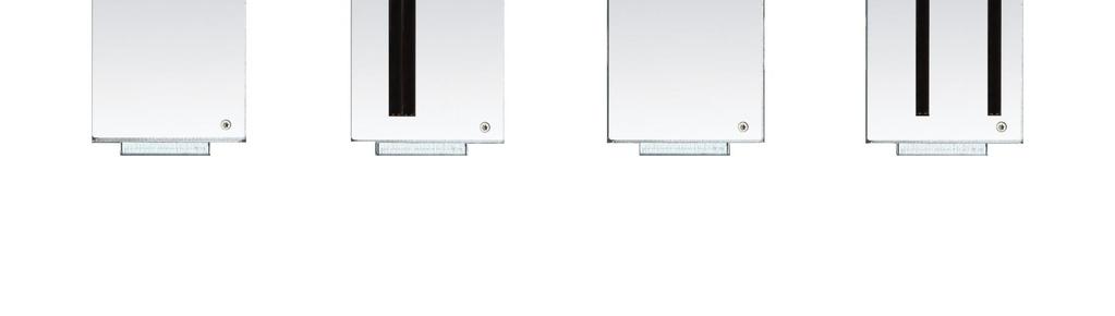
8 Operation instructions SKQ 40-0x SKQ 80-0x SKQ 40-0xM SKQ 80-0xM 1.6. Display elements and connectors SKQ 40-0x SKQ 40-0xM 1. 4 MPEG data stream modulator LED indicators (each with two LEDs) Error (red) = Modulator stream too large (fill level >95%, see on page 16) OK (green) = Fill level O.K HF input 3. RJ-45 Ethernet port 4. 4 HF input LED indicator: Orange = MPEG data stream present, Off = MPEG data stream not present 5. Grounding screw 6. 1 x HF output 7. Fan 8. 2 DC input/output 9. 4 x CI slots Technical changes, design modifications, errors and misprints are subject to change without prior notice.
 Error (red) = Modulator stream too large (fill level >95%, see 3.2.")

9 SKQ 80-0x SKQ 80-0xM 1. 8 MPEG data stream modulator LED indicators (each with two LEDs) Error (red) = Modulator stream too large (fill level >95%, see on page 16) OK (green) = Fill level O.K HF input 3. 2 RJ-45 Ethernet port 4. 8 HF input LED indicator: Orange = MPEG data stream present, Off = MPEG data stream not present 5. Grounding screw 6. 2 HF output 7. Fan 8. 2 DC input/output 9. 2 x CI slots Technical changes, design modifications, errors and misprints are subject to change without prior notice. 9
10 Operation instructions SKQ 40-0x SKQ 80-0x SKQ 40-0xM SKQ 80-0xM 2. Mounting and Installation Notes Before inserting or changing a module, pull the mains plug of the headend base unit from the socket! Observe the operator's manual of the corresponding headend base unit! Observe the operator's manual for the corresponding power supply unit! The antenna system must be installed and grounded according to the DIN EN standard. The headend modules can be operated either in a headend base units or stand-alone with the external power supply unit. The SAT IF inputs can be connected directly to a quattro LNB or to a SAT IF distributor. The plugged cable of the headend supplies the LNB with power. The input distribution can also be done via a multiswitch with up to 16 SAT IF levels Mounting and installation in a headend base unit Install the base plate of the base unit in compliance with the safety regulations defined by the EN standard. Connect the base plate of the base unit with an equipotential bonding cable (copper, minimum 4 mm²) Mounting Every slot in the base unit has a fixing screw in order to install the headend modules. Before the installation, the upper screw must be loosened. When being attached to the output combiner, the module is at the same time mounted on the loosened screw. Please tighten then the screw well Power supply Please pay attention to the maximum number of modules which can be supplied by the power supply unit (see section on page 12). The modules have two identical connecting sockets on the bottom for the power supply. Both are linked together internally. One of both connecting sockets is used to get the operating voltage from the power supply unit or from another module. The second one can be used to loop the operating voltage through to the next module or to the output combiner of the base unit. With the DC patch cable (SKZ 40-00) included in the scope of delivery, the modules can be connected together. While looping the modules through, a maximum of 3 x SKQ 80-0x or 4 x SKQ 40-0x can be connected together. Installation in the headend base unit SKS 4-01: The power supply unit SKZ 5-01, integrated in the headend base unit SKS 4-01, has a DC connecting cable on the output side. This cable is connected to the first module. The other modules are connected to each other using the enclosed DC connecting cable SKZ A separate DC connecting cable SKZ is additionally required to supply the output combiner. The connecting cable SKZ is included in the scope of delivery. Connect the output combiner to the last module Technical changes, design modifications, errors and misprints are subject to change without prior notice.

11 Installation in the headend base unit SKS 8-00: The power supply unit SKZ 6-00 integrated in the headend base unit SKS 8-00 has a short and a long DC connecting cable on the output side. Connect the short DC connecting cable to the first module Connect the long DC connecting cable to the fourth module. The other modules are connected to each other using the enclosed DC connecting cable SKZ Two separate DC connecting cables SKZ are additionally required to supply the output combiner. The connecting cables SKZ are included in the scope of delivery. Connect the output combiner with one SKZ to the last module on the right and with the other SKZ to the third module on the left side. Installation in the base unit SKS 40-00: The power supply unit SKZ 5-04 is not included in the scope of delivery of the base unit. Mount the power supply unit according to the enclosed operating instructions of the power supply unit. The power supply unit has a short and a long DC connecting cable on the output side. Connect the short DC connecting cable to the first module. Connect the long DC connecting cable to the third module. The other modules are connected to each other using the enclosed DC connecting cable SKZ A separate DC connecting cable SKZ is additionally required to supply the output combiner. The connecting cable SKZ is included in the scope of delivery. Connect the output combiner to the last module Technical changes, design modifications, errors and misprints are subject to change without prior notice. 11
12 Operation instructions SKQ 40-0x SKQ 80-0x SKQ 40-0xM SKQ 80-0xM Power supply in the headend base unit A certain number of modules including LNB can be supplied depending on the headend base unit. SKQ 40-0x/M 1.5 A + LNB current consumption SKQ 80-0x/M 3 A + LNB current consumption SKS 4-01 with SKZ 5-01 (10 A) SKS 40-00* with SKZ 5-01 (10 A) SKS 40-00* with SKZ 5-04 (2x10A) SKS 8-00 with SKZ 6-00 (18 A) *Please note: The SKS is supplied without power supply unit and remote control External operation Please note that the installation must be carried out on an even and vertical surface. Any unevenness must be compensated. Fix the module with 2 screws appropriated for the installation surface. Install the module in compliance with the safety regulations defined by the EN standard. Connect the module with an equipotential bonding cable (copper, minimum 4 mm²). For an operation without a basic unit, the outputs of several modules must be combined with a distributor Technical changes, design modifications, errors and misprints are subject to change without prior notice.
13 Power supply by external operation When being operated externally, the module is directly connected to the DC power cable of the separate power supply unit (e.g. SKZ 5-03). Every module has a DC loop output to supply another module with power. A SKZ DC connection cable is included in the scope of delivery of each module. Because of the current carrying capacity, the power supply units can only supply a certain number of modules. The power supply units supply the modules with 16 V DC voltage. The current consumption of all connected modules must not exceed the maximal delivery of the power supply unit used. The remote power rails at the SAT IF inputs must be added to the current consumption of the modules. The current consumption at the SAT IF inputs is limited to 250 ma per input. Please take account of the current consumption of the devices when choosing the LNBs or the multiswitches. Please pay attention to the maximum number of modules which can be supplied by the power supply unit: SKQ 40-0x/M 1.5 A + LNB SKQ 80-0x/M 3 A + LNB SKZ 5-03 (4.5 A) SKZ 5-01 (10A) Connection to DVB-S Connection to the LNBs On the SAT-IF input the headend modules have a remote supply voltage for the LNB and use DiSEqC 1.0 functionalities. Therefore, they can be connected directly to the LNB Multiswitches as input distributors Optionally, you can also use multiswitches as input distributors. The advantage of this solution is that you can set both the SAT IF level and the satellite via the user interface. Changes in the list of programmmes can be made using remote maintenance, so that it is not necessary to change or modify the input distribution on site Connection to DVB-T/T2 or DVB-C Before connecting the antenna cabel, the LNB power has to be switched off (see on page 18). Active DVB-T antennas have to be supplied by an external power supply. The input level has to be dbµv Technical changes, design modifications, errors and misprints are subject to change without prior notice. 13

14 Operation instructions SKQ 40-0x SKQ 80-0x SKQ 40-0xM SKQ 80-0xM 3. Configuration The device is configured via the graphical user interface of the integrated web interface. To access the user interface, you need a standard PC/laptop with a network interface and the actual version of the installed web browser. To connect the network interface of the module to the computer, you need a commercially available network cable. The HTTP protocol is used for communication allowing a worldwide remote maintenance of the systems at various locations via the Internet. Access protection is implemented by means of the password prompt. The octo module features two separate units that each have four tuners, four modulators and one HF output. Every unit has its own web interface and its own static IP address. The following values are preset ex factory: Quattro module IP address: Octo module IP address, left side: IP address, right side: Subnet mask: The computer and the module must be in the same subnetwork. The network part of the IP address of the computer must be set to and the subnet mask must be set to The host part of the network address is required for the identification of the devices and can be assigned in the subnetwork only once. You can allocate to the computer any not allocated host address between 0 and 255. Change the IP address and the subnet mask of your computer accordingly. (e.g.: IP address: and subnet mask: ) Control panel > Network connections > LAN connection >Properties > Internet protocol version 4 TCP/IPv4 > Properties > Use the following IP address: Click OK to save. Start your web browser and enter the IP address of the module: e.g.: Technical changes, design modifications, errors and misprints are subject to change without prior notice.


15 3.1. Login and logout The web-based user interface is protected against unauthorized access. When accessing the user interface, the first thing is the password request. Enter the default password: Ramsen8262 Click the button ENTER PASSWORD. If you are not automatically forwarded to the start page, click then the button OPEN PAGE. In the header, the user can choose the language of the user interface. The possibilities are German (DE) and English (EN). The standard language of the user interface is English. The chosen language applies until the end of the session. To log out, click the button LOG OUT in the header of the website. In the browser, the message "Goodbye! appears. Notes: If the browser is closed while you are still logged in, an automatic logout occurs 2.5 minutes later. If the browser window stays open, there is no automatic logout. It allows monitoring the installation via the web browser. Changing the password: Please change the password immediately after the first commissioning and choose a sufficiently safe password. Keep this password at a safe place. Menu item: Maintenance > Set new password (see on page 27) Changing the IP address: If needed, the modules can be integrated in a network. For this application, some changes must be applied to the network configuration. Menu item Maintenance > System Options (see 0 on page 26) Technical changes, design modifications, errors and misprints are subject to change without prior notice. 15

16 Operation instructions SKQ 40-0x SKQ 80-0x SKQ 40-0xM SKQ 80-0xM 3.2. Front page The relevant information required for the function of the system are shown on the front page. The decisive thing is the quality of the input signals and the utilization of the modulators Bit error rate The bit error rate of all four SAT IF tuners is shown on the left side. The amount of bit errors for the last 1,000,000 transferred bits is calculated. Here you can navigate to the Initialization and Maintenance pages Fill level The fill level of all four modulators is shown on the right side. 100% modulator fill level correspond to the maximal net data rate of the output channel. If the current fill level exceeds the maximal fill level, it may cause image disturbances, e.g. mosaic images. The data rates of the programmes are not constant. They are dynamically changed by the sender. To ensure an undisturbed reception, a reserve must absolutely be observed. We recommend you to set the maximal fill level to 90%. The number of choosen programmes (see 3.4 on page 19) and the configuration of the modulators (see 3.5 on page 24) have an influence to the fill level CI menus If CA moduls are used, the CI menu buttons on the front page are active (see 4.2 on page 31) Technical changes, design modifications, errors and misprints are subject to change without prior notice.

17 Initialization The initialization is subdivided in 3 configuration phases. Phase 1: Tuners. LNB settings, DiSEqC settings, Transponder frequency and transponder search run. Phase 2: Chosse of programmes, programme arrangement. Multiplexing after programme filtering (Remux mode) Transponder crossing multiplexing of FTA programmes (Cross-Multiplex mode) LCN (Logical Channel Numbering) Phase 3: Modulators. Channel spacing, output channel, fine calibration and output level. Modulation, code rate, guard interval, transmission mode Initialization phase 1 During the first phase of the initialization, the tuner settings required for the scan are made and the station scanning is carried out. The four tuners work independently from each other and after the same principle DVB-S (für 8PSK/QPSK- und für Multituner-Kassetten) Choose the tuner with the button Tuner 1 4. Configure the needed settings for all tuners. After all settings have been made, click the button SCAN. A rotating circle is shown on the right side during the scanning process. The SAT IF frequency of the transponder is entered in the input field "Frequency (MHz)". The input fields "LOF Low Band (MHz)" and "LOF High Band (MHz)" correspond to the oscillator frequencies of the LNB in low and high band. The default settings of the oscillator frequencies are 9,750 MHz for the low band and 10,600 MHz for the high band. In the optional field "Polarisation", you can switch from horizontal to vertical. In the optional field "DiSEqC", the DiSEqC command signals can be turned off or set to switch a DiSEqC-enabled multi switch on the positions 1 to 4. If required, the operating voltage for the LNB can be switched off via the optional field "LNB power supply" Technical changes, design modifications, errors and misprints are subject to change without prior notice. 17
 for the receiving channel into the field FREQ (MHz).")
18 Operation instructions SKQ 40-0x SKQ 80-0x SKQ 40-0xM SKQ 80-0xM DVB-C, DVB-T or DVB-T2 (for multi tuner modules) Select any tuner by the help of the buttons Tuner 1 4. Before connecting an antenna cable to an according tuner, the LNB Power has to be set to off Enter the center frequency (see table below) for the receiving channel into the field FREQ (MHz). Note: All other entry fields are not relevant. Modulation and all other important parameter for reception are detected automatically. Enter 3- digits for center frequency Choose Off Channel Input Channel Input Channel Input Channel Input S S S S S S S S S S S S S S S S S S S S S Note: The center frequeny of channels using a bandwith of 7MHz will be rounded down to 3 full digits. For example: center frequency of CH 5 = 177,5 MHz, the according input = Technical changes, design modifications, errors and misprints are subject to change without prior notice.
19 Bit error rate The BIT ERROR RATE is shown in the middle area. The amount of bit errors for the last 1,000,000 transferred bits is calculated Found programmes After a successful station scanning, the radio and TV stations are shown in the area "FOUND PROGRAMS". The table contains information about programme type and encoding Initialization phase 2 In the initialization phase 2, the found programmes are subdivided by tuner. The programme name, the programme type and information about the encryption are shown. After the station scanning in initialization phase 1 all programms are activated. The programms of the tuner 1 to 4 are deticated to the modulators 1 to 4. All lines of the programme table have in the "Modulator" column four colored buttons M1 to M4. The buttons correspond to the four modulators. The allocation of the buttons is given in the COLOR CODES legend. You can assign programmes to modulators in remux mode or in cross multiplex mode. Important: With each programme you asign to an modulator, the data rate rises. The performed modifications are only taken over by the system when you click the button SAVE CHANGES Remux mode If the transport stream IDs of the four modulators and the network ID are set on "auto", the module works in the Remux mode. In this mode, the IDs from the set transponder and from the satellite are used and forwarded to the modulators with virtually no changes. Assigning programmes Every tuner is assigned to a modulator. The programmes of the tuner can only be assigned to the associated modulator. Click onto the modulator button, the programme is assigned to the modulator. For example click in table TUNER 1 on the button M1. The programme is assigned to modulator 1. The button of the modulator is highlighted in color Technical changes, design modifications, errors and misprints are subject to change without prior notice. 19


20 Operation instructions SKQ 40-0x SKQ 80-0x SKQ 40-0xM SKQ 80-0xM Choosen programs for modulator 1 Chose the programmes for TUNER 1 to TUNER 4. A new click on a button allow the assignment to be canceled. The modulator buttons fades then again. Scrambled programmes Scrambled programmes are indicated by the abbreviation CA in the column Encryption. They can be forwarded in encrypted form, or be decrypted in the SKQ 40-04/M or SKQ 80-02/M module by means of an integrated CA module (see 4. Use of CA modules at page 30) Cross Multiplex Mode The cross multiplex mode is used: To split the programmes of a transonder to several modulators. To merge pogams of several transponders into one output channel. Transmission capacities in the distribution networks can be optimized. Change the network ID to a value greater than zero. The IDs of the transport streams are automatically incremented by one to four, the cross multiplex mode is activated Technical changes, design modifications, errors and misprints are subject to change without prior notice.

21 Assigning programmes to the modulators In the cross multiplex mode, the tuners are no longer assigned to the modulators. Programs, which are assigned to modulator 1 Click the table Tuner 1 and in the table Tuner 3 on the buttons M1. The three programmes are assigned to modulator Technical changes, design modifications, errors and misprints are subject to change without prior notice. 21

22 Operation instructions SKQ 40-0x SKQ 80-0x SKQ 40-0xM SKQ 80-0xM Spliting the programmes of a transonder If there are to much programms transmitted in one transponder, they can be splitted to several modulators. Make the same settings to two tuners in initialization phase 1. Start the scanning of programmes. Change the network ID to a value greater than zero. The programms of one transponder are spitted to two modulators For example: choose modulator M1 for two programmes ans modulator M2 for two other programmes. Importend: The cross multiplex mode can not be used for CA programmes, which are encrypted in the haeadend! A splitted transponder works like two transponders. If you use the cross multiplex mode in several modules, the network IDs of the modules have to be different Technical changes, design modifications, errors and misprints are subject to change without prior notice.

23 LCN (Logical Channel Numbering) During the scan of TV stations, the stations are usually saved in the sequence of the channel lists in tuner 1-4. The LCN function enables channel allocation for the station scan of the TV devices. The TV device must support the LCN function. LCN can be used in REMUX as well as in Cross-Multiplex-Mode. Insert the desired LCN into the input field. Example: [Your favorite station] on channel 1, [Your second favorite station] on channel 2 and so on. To delete the allocation, the LCN number in the corresponding field must be deleted. LCN 1 LCN 2 When all settings in the station list have been made, click the button SAVE CHANGES Technical changes, design modifications, errors and misprints are subject to change without prior notice. 23

24 Operation instructions SKQ 40-0x SKQ 80-0x SKQ 40-0xM SKQ 80-0xM 3.5. Initialization phase 3 In phase 3, the modulators are configured. The output channels are compulsory assigned to adjacent channels Configuration of the modulator The first modulator can be set to any output channel between S2 and CH 87. The other three modulators are automatically set by incrementing the output. For example: modulator 1 = Channel 21 Output channels and channel spacing DVB-C modulation: DVB-C symbol rate: Output level / Level setting Vernier adjustment: modulators 2, 3 and 4 = Channels 22, 23 and 24 According to the BG standard, the special channels S2 to S20 and channels 5 to 12 in the VHF range have a bandwidth of 7 MHz. However, a higher bandwidth allows more data to be transmitted. This is why in the frequency range in question MHz channels are also available in the 8 MHz channel spacing. These channels are D1 to D24 with a bandwidth of 8 MHz.The upper special channel range and the UHF channels, likewise with a bandwidth of 8 MHz, follow D24 without a gap. The UHF range has been extended by channels CH70-CH87. However, when using this range, you have to check whether all receivers support the frequencies above 862 MHz. With DVB-C modulation, you can choose between 32QAM, 64QAM, 128QAM and 256QAM. 256QAM enables the highest data transmission rate, but it also requires the best network quality. The DVB-C symbol rate can be freely set between 1000 and The standard value is Some networks also work with When working with a bandwidth of 7 MHz, 6111 is customary. The Output Level options include attenuation and deactivation of the modulator. Each of the four modulators is set separately. The max. output level of approx. 100 dbµv is reached with an Output Level setting of 20 db. The vernier adjustment of the output channel is performed in 0.5 MHz steps Technical changes, design modifications, errors and misprints are subject to change without prior notice.
25 Fill level The fill level depends on the number of activated channels in the channel list (menu item Phase 2) If the CROSS MULTIPLEX MODE is active, it must be ensured that the maximum number of activated channels in one modulator is not exceeded. The data rate of the channels on the DVB-S/S2 transponders may vary depending on the image contents and on the transmission quality. To ensure an undisturbed reception, a reserve must absolutely be observed. We recommend you to set the maximum fill level to 95%. If the current fill level exceeds the maximal fill level, it may cause image disturbances, such as mosaic images. The error LEDs on the front panel will light up in red in this case. The data rate of a DVB-C channel depends on the selected channel bandwidth (7 or 8 MHz), the set symbol rate and the DVB-C modulation (QAM32;64;128;256) of the modulator. If the displayed data rate exceeds 95%, there are different possibilities to change it: Change to a channel with a bandwidth of 8 MHz if a 7 MHz channel was selected previously. Set DVB-C modulation to a larger value, for example, change from QAM 64 to QAM 128. Reduce the number of selected channels in the channel list. If the connected receivers support this option, increase the symbol rate Selected Programmes The programme table Selected Programmes shows the programmes that were activated in phase 2 and that have been selected in the Cross Multiplex Technical changes, design modifications, errors and misprints are subject to change without prior notice. 25


26 Operation instructions SKQ 40-0x SKQ 80-0x SKQ 40-0xM SKQ 80-0xM 3.6. Maintenance The menu entry MAINTENANCE enables software updates, changing the IP address, changing the password, restarting the module and erasing service data. Important: If you stay on the maintenance page for more than 2.5 minutes, an automatic logout will occur and you will have to repeat the login procedure Updating firmware/software New software for the interface can be installed under SOFTWARE FILE. Software updates are available at Download. The module will be automatically rebooted after an update. The setted parameters will not be lost after an update. Firmware can only be updated at the factory Changing the IP address The IP address, Netmask and the Gateway can be changed in the menu MAINTENANCE > SYSTEM OPTIONS. The SAVE CHANGES button confirms and saves the changes. When the IP address has been changed, the device will reboot automatically. The new IP address has to be entered in the web browser and the enter password dialog will be displayed Technical changes, design modifications, errors and misprints are subject to change without prior notice.


27 Changing the password The default password should be changed right after commissioning the module. The default password can be changed in the menu MAINTENANCE > SET NEW PASSWORD. The default password is: Ramsen8262. Any new password must be 8-10 characters (letters and/or digits) long. After changing the password, the module must be rebooted. After this the user must log in with the new password Rebooting Clicking on the REBOOT button reboots the module. After rebooting, the password must be entered again. Note: If SAT signals are temporarily unavailable (e.g. due to snow), the module will reboot every 10 minutes. This ensures that all configured programmes will be available once the signal becomes available again Erasing service data In the section ERASE SERVICE DATA you can erase the settings from phase 2. The transponder data must be read again for tuners 1-4 by executing a scan. The module is also set to remux mode Technical changes, design modifications, errors and misprints are subject to change without prior notice. 27


28 Operation instructions SKQ 40-0x SKQ 80-0x SKQ 40-0xM SKQ 80-0xM Save Initialization Data In the section SAVE SYSTEM INITILIZATION DATA TO FILE you can save the current initilization data from phase 1 to 3 into a file on your computer. Click on SAVE. The data will be saved in a file called config.dat at the download folder on your computer. Click on PDF TO PRINT. A PDF will be generated and saved in a file called config.pdf at the download folder on your computer. Note: Password and IP adress will not be saved Upload Initialization Data In the section UPLOAD SYSTEM INITILIZATION DATA FROM FILE you can upload the initiaization data from a file to the modul. Choose a configuration file. Click on UPLOAD. The upload will take a few seconds. After the upload you have to log in again Technical changes, design modifications, errors and misprints are subject to change without prior notice.

29 Device name In the section DEVICE NAME you can set a new device name for the module. Enter a name in the field SET NEW DEVICE NAME. Click on SAVE CHANGES. The new device name is shown at the login Technical changes, design modifications, errors and misprints are subject to change without prior notice. 29
 can be inserted into the CI-slots at the front side of the SKQ 40-04.")

30 Operation instructions SKQ 40-0x SKQ 80-0x SKQ 40-0xM SKQ 80-0xM 4. Use of CA modules 4.1. Insertion of CA modules Up to four CA modules (CAM1 CAM4) can be inserted into the CI-slots at the front side of the SKQ Up to two CA modules (CAM1 left/cam1 right) can be inserted into the CI-slots at the front side of the SKQ Carefully insert the CA modules carefully to the corresponding CI slot without exerting force. Note: Each CAM corresponds and gets access only to according tuner: SKQ 40-04/M CAM 1 - tuner 1 CAM 2 - tuner 2 CAM 3 - tuner 3 CAM 4 - tuner 4 SKQ 80-02/M CAM 1 left - tuner 1 left unit CAM 1 right - tuner 1 right unit Technical changes, design modifications, errors and misprints are subject to change without prior notice.


31 4.2. CI menu for SKQ 40-04/M and SKQ 80-02/M In the CI menus, settings of CA modules can be made for SKQ 40-04/M and SKQ 80-02/M. The buttons for opening the CI menu will be activated after the modules have been plugged in and initialised. Active buttons for the CI menu. Click one of the buttons. The corresponding CI menu is displayed Using CI menu The content of the CI menu depends on the CAM manufacturer and the card being used. Depending on the manufacturer, various settings are possible. Information on validity and authorisation are the most important. Please observe the operating instructions provided by the manufacturer. Cursor position The Content depends on used CAM Input and navigation field According to used CAM different settings can be done. Most important is getting information about authorisation. The input and navigation field is used for navigation within the CI menu. Use Up or Down to reach a higher or lower selection point. Use OK to enter a corresponding sub menu or confirm a selection. Use Menu to come back to the next superordinate level. Use Exit to leave the menu Technical changes, design modifications, errors and misprints are subject to change without prior notice. 31

32 Operation instructions SKQ 40-0x SKQ 80-0x SKQ 40-0xM SKQ 80-0xM 4.3. Decryption of programmes Scrambled programmes are indicated by the abbreviation CA in the encryption column of the tuner table. By default, encryption is disabled. The programm will be transferred to the modulator in encrypted form and must be decrypted when reaching the receiver. If CA modules are plugged in, the corresponding programmes can be decrypted. Activate the decryption Activate the yes option in the decryption column. The programm will be transferred to the modulator in decrypted form Technical changes, design modifications, errors and misprints are subject to change without prior notice.
33 5. Technical specifications 5.1. Input multituner SKQ 40-0xM SKQ 80-0xM Ducts 4 8 Multituner 4 DVB-S/S2/T/T2/C 8 DVB-S/S2/T/T2/C Input frequency range TERR SAT Input level TERR SAT MHz MHz dbµv dbµv/ dbm LNB voltage 13/17 V; 22 khz on/off; DiSEqC 1.0 Max. LNB current (per input) 250 ma Modulation process 8PSK/QPSK COFDM, 32k, 8k und 2k QAM 16, 32, 64, 128, 256 Symbol rate Error correction MS/s automatic Transport stream MPEG-2 ISO/IEC MPEG-4 ISO/IEC Connectors 4 F female 8 F female 5.2. Input DVB-S/S2 tuner SKQ 40-0x SKQ 80-0x Ducts 4 8 Tuner 4 DVB-S/S2 8 DVB-S/S2 Input frequency range SAT Input level MHz dbµv/ dbm LNB voltage 13/17 V; 22 khz on/off; DiSEqC 1.0 Max. LNB current (per input) Modulation process Symbol rate Error correction 250 ma 8PSK/QPSK MS/s automatic Transport stream MPEG-2 ISO/IEC MPEG-4 ISO/IEC Connectors 4 F female 8 F female Technical changes, design modifications, errors and misprints are subject to change without prior notice. 33
34 Operation instructions SKQ 40-0x SKQ 80-0x SKQ 40-0xM SKQ 80-0xM 5.3. Output/General Output Output frequency range MHz Output channels S2 K87 Modulation QAM 32, 64, 128, 256 Transmission symbol rate M'symbol sec Output level dbµv MER > 40 db Connectors 1 F plug Quickfix 2 F plug Quickfix General Data interface 1 RJ 45 2 RJ 45 Current consumption 16V=/1.5 A 16V=/3 A Ambient temperature range -10 C +50 C Dimensions approx. 72 mm 218 mm 129 mm Technical changes, design modifications, errors and misprints are subject to change without prior notice.
35 Technical changes, design modifications, errors and misprints are subject to change without prior notice. 35

36 Operation instructions SKQ 40-0x SKQ 80-0x SKQ 40-0xM SKQ 80-0xM Technical changes, design modifications, errors and misprints are subject to change without prior notice.
MK 8-00 MK MK 8-06 MK 16-06
 MK 8-00 MK 16-00 MK 8-06 MK 16-06 Multituner DVB-C/DVB-T compact headend Operation instructions Operation instructions MK 8-00 MK 16-00 MK 8-06 MK 16-06 Table of contents 1. Product description... 4 1.1.
Quick installation and configuration guide STC
 Quick installation and configuration guide STC 200 REF. 4466 Contents 4 Introduction 4 General description 5 General use of the headend 6 Initial installation and configuration 6 Assembly, connection
MyM-3S Micro Master. Installation Guide. English. design for TV
 MyM-3S Micro Master Installation Guide design for TV 1 CONTENT 1. Introduction 2. Unpacking the unit 3. Connections and indications 4. IP settings 5. Menus and settings 5.1 Overview menu 5.2 Input settings
HD-1603 Single Input MPEG-4 DVB-T HD Encoder/Modulator User Guide and Install Manual
 ZyCastR digi-mod HD Range digi-mod HD-1603 www.digi-modbyzycast.com HD-1603 Single Input MPEG-4 DVB-T HD Encoder/Modulator User Guide and Install Manual Table of Contents www.digi-modbyzycast.com Safety
SAT IF distribution system
 7. Technical specifications Type cs43 RF input frequency range pr. 50-350 MHz inputs number 4 level pr. 55...88 dbµv 60...93 dbµv symbol rate 3 45 Ms/s return loss/impedance > 0 db/75 Ω LNB powering/control
User Manual. UNIVERSE Ref. 8600
 User Manual UNIVERSE Ref. 8600 No part of this manual may be copied, reproduced, transmitted, transcribed or translated into any language without permission. Unitron reserves the right to change the specifications
CompactMax-2 DVB-S/S2 TO DVB-T2 TRANSMODULATOR - 0 MI2100 -
 CompactMax-2 DVB-S/S2 TO DVB-T2 TRANSMODULATOR - 0 MI2100 - SAFETY NOTES Read the user s manual before using the equipment, mainly "SAFETY RULES" paragraph. The symbol on the equipment means "SEE USER
Digital Compact Headends
 Johansson introduces the range of Digital Compact Headends, known as Colosseum. Already shortly after their introduction in Germany, these compact TV distribution stations were recommended by several magazines
TV4U QUAD DVB-S2 to DVB-C TRANSMODULATOR
 INSTRUCTION MANUAL Features of the new DVB-C transmodulators line Through the use of the FPGA technology the transmodulators provides the highest performance at the lowest price. Four carriers are formed
CM 3S-TC. Triple Transmodulator 8PSK-COFDM/QAM. User manual
 CM 3S-TC 082016 Triple Transmodulator 8PSK-COFDM/QAM User manual 1 1. Accessories... 1 2. General Description... 2 3. Installing and connections... 4 3.1. Installing and general connections... 4 3.2. Installation
User Manual. UNIVERSE Ref. 8600
 User Manual UNIVERSE Ref. 8600 No part of this manual may be copied, reproduced, transmitted, transcribed or translated into any language without permission. Unitron reserves the right to change the specifications
User manual Transmodulators. Ref. 5103S/5103T/5103Q/5130
 User manual Transmodulators Ref. 5103S/5103T/5103Q/5130 Contents 1 Introduction 2 1.1 The ProQuad range................................ 2 1.2 Modular system solution.............................. 4 1.3
user manual Colosseum 8500D
 user manual Colosseum 8500D No part of this manual may be copied, reproduced, transmitted, transcribed or translated into any language without permission. Unitron reserves the right to change the specifications
MyM Pro 3S/6S Installation guide
 MyM Pro 3S/6S Installation guide CONTENT 1. Introduction 2. Unpacking the unit 3. Connections and indications 4. IP settings 5. Menus and settings web ui 5.1 Overview menu 5.2 Input settings 5.3 Output
User Manual. UNIVERSE Ref SW Release
 User Manual UNIVERSE Ref. 8600 SW 1.3.0.Release No part of this manual may be copied, reproduced, transmitted, transcribed or translated into any language without permission. Unitron reserves the right
Table of Contents. 1. Safety Use. 2. General Description. 3. Connection Diagram. 4. Operations and Management. 4.1 Display Status. 4.
 DTM-HD01 Thank you for buying this encoder modulator. Please read this manual carefully to install, use and maintain the encoder modulator in the best conditions of performance. Keep this manual for future
CompactMax-4 DVB-S/S2 TO ISDB-T TRANSMODULATOR - 0 MI2101 -
 CompactMax-4 DVB-S/S2 TO ISDB-T TRANSMODULATOR - 0 MI2101 - SAFETY NOTES Read the user s manual before using the equipment, mainly "SAFETY RULES" paragraph. The symbol on the equipment means "SEE USER
DXI-800 DVB-S/S2/T to IP streamer User Manual
 DXI-800 DVB-S/S2/T to IP streamer User Manual 1. Purpose of use DXI-800 is HD compatible IP streamer designed for a processing satellite and terrestrial signals to data broadcast (IP) connected to Ethernet.
MyM Pro T2 Installation guide
 MyM Pro T2 Installation guide CONTENT 1. Introduction 2. Unpacking the unit 3. Connections and indications 4. IP settings 5. Menus and settings web ui 5.1 Overview menu 5.2 Input settings 5.3 Output settings
QAM MODULATOR CI. 4 x DVB-S/S2/T/T2/C+CI 4 x DVB-T/C + IP. Operation Manual
 QAM MODULATOR CI 4 x DVB-S/S2/T/T2/C+CI 4 x DVB-T/C + IP Operation Manual 1 1. IMPORTANT SAFETY PRECAUTIONS INFORMATION READ THE FOLLOWING WARNINGS BEFORE YOU USE YOUR DEVICE WARNING The following safety
Simple Media Platform Quick Installation Guide V1.0-N. Simple Media Platform. Quick Installation Guide
 Simple Media Platform Quick Installation Guide 1. Installation Instruction 1.1 Mounting unit to a 19 rack When selecting the installation site, try to comply with the following: Protective Ground - The
Figure 1: V 713 CI plug-in card
 Version 04-2013A Device description Device description The delivery consists of the following parts: V 713 CI and X-DVB-CT2/PAL duo CI plug-in cards 2 connection cables with F connectors, 450 mm & F socket-f
DVISm. DVISm - Mini Digital Video Insertion System. Quick Start Guide. Patent Pending
 DVISm Patent Pending DVISm - Mini Digital Video Insertion System Quick Start Guide Although every effort has been taken to ensure the accuracy of this document it may be necessary, without notice, to make
TV4U DVB-S2 to DVB-S2 TRANSMODULATOR
 TV4U to TRANSMODULATOR TV4U to TRANSMODULATOR INSTRUTION MANUAL TV4U to TRANSMODULATOR The main application of to transmodulator Experience of MVDS terrestrial broadcasting shows that carrier must be restored
Z-IP Stream 004/008. User Guide and Installation Manual. Four or Eight Input QAM Encoder / Modulator
 Z-IP Stream 004/008 User Guide and Installation Manual Four or Eight Input QAM Encoder / Modulator MPEG-2 / H.264 HD ENCODER with QAM /IP/ & ASI Outputs Contents Safety Precautions... 3 Package Contents...
Single cable multiswich programmer PC102W
 Single cable multiswich programmer PC102W 1. Product description The PC102W - single cable multiswich programmer (in the text - programmer) is useful instrument while configuring and troubleshooting SAT
IxStream Headend. Quick Guide - Begin working with the IxStream headend. IX-Streamer, rev 1.1
 IxStream Headend Quick Guide - Begin working with the IxStream headend IX-Streamer, rev 1.1 Introduction... 3 Example setup... 3 Access the headend... 4 Important Concepts... 5 Push Config... 5 EMM...
16 channels transmodulator S2C16
 16 channels transmodulator S2C16 Vers. 1.01 USER S MANUAL S2C16 - SAT to QAM transmodulator 1. Product description S2C16 is a 16 channel transmodulator with DVB-S/S2 input and DVB-C output. It has 4 main
AVE HOME FAGOR CVBS TO DVB-T ENCODER MODULATOR. Fagor Electr6nica
 AVE HOME CVBS TO DVB-T ENCODER MODULATOR FAGOR Fagor Electr6nica TABLE OF CONTENTS 1. SPECIFICATIONS... 12 1.1 Product Overview... 12 1.2 Appearance and Description... 12 1.3 Diagram... 13 1.4 Characteristics...
MS8631 RF WIDEBAND AMPLIFIER. MS RACK ADAPTER for Digi-8
 D I G I T A L H E A D E N D S Y S T E M D I G I - 8 D I G I - 6 D I G I - 8 T E C H N I C A L C H A R A C T E R I S T I C S : Ideal for satellite & terrestrial digital TV distribution in hotels and communities
HDTV Digital ASI PHDA 8007 ASI. English. Phone: +49 (0) 911 / Fax: +49 (0) 911 / Internet:
 911 / Fax: +49 (0) 911 / Internet:") HDTV Digital ASI PHDA 8007 ASI KLASSE CLASS English GSS Grundig SAT Systems GmbH Beuthener Strasse 43 D-90471 Nuremberg Phone: +49 (0) 911 / 703 8877 Fax: +49 (0) 911 / 703 9210 E-mail: info@gss.de Internet:
HDTV Digital ASI PHDA 8007 ASI KLASSE CLASS English GSS Grundig SAT Systems GmbH Beuthener Strasse 43 D-90471 Nuremberg Phone: +49 (0) 911 / 703 8877 Fax: +49 (0) 911 / 703 9210 E-mail: info@gss.de Internet:
AMD-53-C TWIN MODULATOR / MULTIPLEXER AMD-53-C DVB-C MODULATOR / MULTIPLEXER INSTRUCTION MANUAL
 AMD-53-C DVB-C MODULATOR / MULTIPLEXER INSTRUCTION MANUAL HEADEND SYSTEM H.264 TRANSCODING_DVB-S2/CABLE/_TROPHY HEADEND is the most convient and versatile for digital multichannel satellite&cable solution.
PREMIUM HEADEND SYSTEM
 B-LINE NEW modules for processing of 8PSK/QPSK, COFDM, QAM, ASI, Analog TV and Audio/Video signals Modular Headend system featuring Hot Swap technology and automatic power supply redundancy Frequency a
It receives contents from 4 DVB-T/T2, DVB-S/S2 or DVB-C transponders/muxes and broadcasts them in 4 DVB-T, DVB-C or IP output channels.
 + HTI HEADEND It receives contents from DVB-T/T, DVB-S/S or DVB-C transponders/muxes and broadcasts them in DVB-T, DVB-C or IP output channels. Quad universal tuner Output DVB-T or DVB-C selectable channels
Operation and Installation Guide
 Operation and Installation Guide HDS2800 Series Encoder Modulator High Definition (HD) Digital COFDM MPEG2 and H.264 Modulator with IP Multicast. 19 Rack Mount Revision 4.0 Firmware version Released File
HD-1600 Single Input MPEG-4 DVB-T HD Encoder/Modulator User Guide and Install Manual
 digi-mod HD Range digi-mod HD-1600 www.resi-linx.com HD-1600 Single Input MPEG-4 DVB-T HD Encoder/Modulator User Guide and Install Manual Table of Contents Safety Precautions 2 Package Contents 2 Product
HD4112 Quad HDMI MPEG2 HD DVBT Encoder Modulator U S E R M A N U A L
 HD4112 Quad HDMI MPEG2 HD DVBT Encoder Modulator U S E R M A N U A L HD4112 Manual Rev 1 Contents 1. GENERAL 1.1 Description 1.2 Specifications 2. INSTALLATION 2.1 What s in the Box 2.2 Connection 2.2.1
The new standard for customer entertainment
 The new standard for customer entertainment TDH 800 basic headend system your ultimate connection 2 TRIAX TDH 800 New standard for basic headend systems The TDH 800 is a basic headend system designed to
Professional 4-Channel DVB Receiver and Transmodulator Item: 5213
 IDLV-3440DM Professional 4-Channel DVB Receiver and Transmodulator Item: 5213 IDLV-3440DM integrates 4 DVB Receiver and Transmodulator in one 1U 19 chassis. It provides operators an ideal DTV headend setup
User Manual. HDMI Modulator Ref & SW Release
 User Manual HDMI Modulator Ref. 8201 & 8202 SW 1.1.1.Release No part of this manual may be copied, reproduced, transmitted, transcribed or translated into any language without permission. Unitron reserves
DMOD1200MS. HDMI Modulator. User Manual PLEASE READ THE MANUAL COMPLETELY BEFORE USE V.17.09
 DMOD1200MS HDMI Modulator User Manual PLEASE READ THE MANUAL COMPLETELY BEFORE USE V.17.09 CONTENTS 1. INTRODUCTION 1.1. Product Description 1.2. Package Contents 1.3. Hardware Installation 1.4. Safety
Figure 1: V 613 CI plug-in card
 Version 02-2013A Device description Device description The delivery is comprised of the following parts: V 613 CI and X-DVB-S2/PAL duo CI plug-in card 2 connection cables with F connectors, 450 mm & F
Multi Channel Programmable Filter-Amplifier. User Manual I-II III V-U SAT. Stop Channel SAT Slope Start Channel SAT ON / OFF.
 R Ref. : 6602 Multi Channel Programmable FilterAmplifier User Manual Digital Terrestrial B III B III VHFUHF UHF1 24V 0 22 khz UHF2 24V 18V 24V 24V 13V 0V UHF3 III III VU GND R MULTI CHANNEL PROGRAMMABLE
Operation and Installation Guide
 Operation and Installation Guide HDS2800 Series Encoder Modulator High Definition (HD) Digital COFDM MPEG2 and H.264 Modulator with IP Multicast. 19 Rack Mount Wall Mount Revision 0.1 Firmware version
VIDEO GRABBER. DisplayPort. User Manual
 VIDEO GRABBER DisplayPort User Manual Version Date Description Author 1.0 2016.03.02 New document MM 1.1 2016.11.02 Revised to match 1.5 device firmware version MM 1.2 2019.11.28 Drawings changes MM 2
CSE 2800 digital main unit
 CSE 2800 digital main unit CSE 2800 Main unit 325001 Conversion Pcs 16 x digital SAT Suitable for adjacent channels Input/output impedance/ Programming Yes Integrated Control Unit 75 Software update via
Applications & Features of the SB- SDQM- 2130
 Applications & Features of the SB- SDQM- 2130 Retrofit Existing 12 in 1 Analog Head Ends Into Standard Definition QAM Analog to Digital in one easy step Allows insertion of operators scrambled programming
User s Manual HDMI Modulator ATSC 8VSB/QAM 65/256. Model No : HDM100
 User s Manual HDMI Modulator ATSC 8VSB/QAM 65/256 Model No : HDM100 Contents 1. Safety Instructions & Precautions. 1 2. Operation Guide.. 2 2-1. Connection Diagram. 2 2-2. Front Panel.... 3 2-3. Rear Panel.....
Assembly Instructions
 Assembly Instructions English GSS Grundig SAT Systems GmbH Beuthener Straße 43 D-90471 Nuremberg Grundig SAT Systms HDTV Digital QAM PHDQ 2002 BC PHDQ 3002 BC PHDQ 4002 BC PHDQ 5002 BC KLASSE ACLASS Phone:
Channel processing equipment
 7. Technical specifications Type C / ttx420c / ttx420 RF input freuency range 950-2150 MHz 47-862 MHz LNB powering/ control 0/13/18 V & 22 khz, 500 ma max. DiSEC 1.0, EN50607, EN50494 12 V 100 ma level
SATFINDER 3 HD SLIM USER GUIDE
 SATFINDER 3 HD SLIM USER GUIDE INDEX General Safety..... 3 Key Features..... 4 Panel Keypads... 5 Accesory.. 6 Satellite Search...... 7 Spectrum..... 8 Cross Polarisation... 9 Packet TP Levels.... 9 Multi
The first TV Smart Headend designed for Hospitality SOLUTIONS FOR IN-ROOM ENTERTAINMENT PROVIDERS AND INTEGRATORS
 The first TV Smart Headend designed for Hospitality SOLUTIONS FOR IN-ROOM ENTERTAINMENT PROVIDERS AND INTEGRATORS 1 FLOW IN...3 FLOW SEC...4 FLOW ENC...5 FLOW OUT...6 FLOW HUB...7 FLOW BASE...8 FLOW PSU...9
MyM Pro Installation Guide
 MyM Pro Installation Guide www.wisi.se TABLE OF CONTENTS 1. INTRODUCTION 3 2. UNPACKING THE UNIT 4 3. CONNECTIONS AND INDICATIONS 5 4. IP SETTINGS 6 4.1 TCP/IP settings for Windows XP...............................
Johansson Catalogue EDITION 2013
 Johansson Catalogue EDITION 2013 Johansson More than a name! Johansson is the quality brand of the Unitron Group, an international RF electronics company, headquartered in Poperinge, Belgium. Introduction
ADR-1000AS Compact Modular SMATV Headend
 ADR-1000AS Compact Modular SMATV Headend ADR-1000AS is a compact modular SMATV headend, supporting up to 16 channels in one 19 4U chassis. It integrates multiple functions including DTV signal reception,
TSF 310 CI USER S MANUAL
 TSF 310 CI USER S MANUAL NOTE: This user s guide is adapted to software version v.0.1.47 of TSF 310 CI dated 09/04/2014. For future software updates, you can download the user s guide from the following
WISI COMPACT HEADEND Channel Processing
 WISI COMPACT HEADEND Channel Processing The new WISI COMPACT HEADEND System OH is best suited for use in small CATV networks, medium sized residences, high rise buildings, recreational facilities, hospitals,
SAT IF distribution technologies. Multiswitches and single cable multiswitches for 1, 2, 3 or 4 SAT positions
 SAT IF distribution technologies Multiswitches and single cable multiswitches for 1, 2, 3 or 4 SAT positions Cascadable Wide product range Suitable for multimedia Single cable acc. to EN 50607, compatible
T3316 IP QAM Modulator User Manual
 T3316 IP QAM Modulator User Manual SW Version: 1.02 HW version: 0.70.0.0 Web NMS version: 1.02 Intended Audience About This Manual This user manual has been written to help people who have to use, to integrate
Noise Detector ND-1 Operating Manual
 Noise Detector ND-1 Operating Manual SPECTRADYNAMICS, INC 1849 Cherry St. Unit 2 Louisville, CO 80027 Phone: (303) 665-1852 Fax: (303) 604-6088 Table of Contents ND-1 Description...... 3 Safety and Preparation
8-Way Professional Demodulator & IPTV Streamer
 8-Way Professional Demodulator & IPTV Streamer Model: Main Feature: 8 DVB-S2/S, DVB-C, DVB-T2/T or DTMB or ATSC or ISDB-T Tuner Inputs Tuner RSSI, received signal strength, Eb/N0, C/N and BER monitoring
PCU IP Streamer. User manual MADE IN GERMANY
 PCU 4131 IP Streamer User manual MADE IN GERMANY 0901932 1 Contents 1. Mounting and safety instructions 3 2. General information 5 3. Description 5 4. Scope of delivery 5 5. Input circuit 5 6. Assembly
PCU Compact Headend. User manual MADE IN GERMANY V3
 PCU 4141 Compact Headend User manual MADE IN GERMANY 0901789 V3 Contents 1. Mounting and safety instructions 3 2. General information 5 3. Description 5 4. Scope of delivery 5 5. Input circuit 5 6. Assembly
Xpresionn Digital Terrestrial Receiver. User Guide
 Xpresionn 2150 Digital Terrestrial Receiver User Guide GENERAL INFORMATION...3 A) SAFETY PRECAUTIONS...3 B) MAIN FEATURES...4 C) CONTENTS OF THE PACKAGING...4 D) REMOTE CONTROL...5 INSTALLATION...6 A)
Professional Headend Solutions. Device manual. SAT-TV Transmodulator. DVB-S/ -S2 (8x QPSK/ 8PSK) 4x CI DVB-C (8x QAM) A-QAMOS-4CI Part N o : 5102.
 4x CI DVB-C (8x QAM) A-QAMOS-4CI Part N o : 5102.") Professional Headend Solutions Device manual A-QAMOS-4CI Contents 1. Safety and operating instructions... 3 2. Device variants... 3 3. Software options... 3 4. General... 3 5. Functional description...
Professional Headend Solutions Device manual A-QAMOS-4CI Contents 1. Safety and operating instructions... 3 2. Device variants... 3 3. Software options... 3 4. General... 3 5. Functional description...
The new standard for customer entertainment
 The new standard for customer entertainment TDH 800 headend system your ultimate connection 2 TRIAX TDH 800 New standard for headend systems The TDH 800 is a headend system designed to provide cost effective
User Manual. SCR Multiswitch Ref. 9744SKY, 9746SKY, 9748SKY
 User Manual SCR Multiswitch Ref. 9744SKY, 9746SKY, 9748SKY No part of this manual may be copied, reproduced, transmitted, transcribed or translated into any language without permission. Unitron reserves
SZU OPERATING INSTRUCTIONS SAT NAVI
 SZU 21-00 O P ER ATI N G I N S T R U C T I O N S SAT NAVI Operation Instructions SZU 21-00 Safety Notes Turn off the receiver or any used power supply before installing, to avoid short-circuit. Installation
DVIS. DVIS - Digital Video Insertion System. Quick Start Guide. Patent Pending
 DVIS Patent Pending DVIS - Digital Video Insertion System Quick Start Guide Although every effort has been taken to ensure the accuracy of this document it may be necessary, without notice, to make amendments
HD168Bi Quad CVBS/HDMI HD DVBT Encoder Modulator U S E R M A N U A L
 HD168Bi Quad CVBS/HDMI HD DVBT Encoder Modulator U S E R M A N U A L Contents 1. GENERAL 1.1 Description 1.2 Specifications 2. INSTALLATION 2.1 What s in the Box 2.2 Connection 2.2.1 DEVICE Programming
User Manual. Profiler Revolution Ref PATENT PENDING. SW Version 1.3.0
 User Manual Profiler Revolution Ref. 6700 PATENT PENDING SW Version 1.3.0 CONTENTS 1. INTRODUCTION... 3 1.1. Product description... 3 1.2. Typical installation... 3 1.3. Package contents... 3 1.4. Hardware
M5-H002. Multiview T-35. DVB-T to PAL / 5 channels on all TV s
 120531 M5-H002 Multiview T-35 DVB-T to PAL / 5 channels on all TV s Contents Multiview... 3 Features... 3 Caution... 3 Front & Rear Panel... 4 Connecting... 5 Programming... 6 Information... 7 Installation...8
MANUAL ENG DT-1600 ENGLISH. Also contains Menu options and data for built-in modulator Data for broadband amplifier QPSK
 ENG-1 030206 01261-3 ENGLISH Also contains Menu options and data for built-in modulator Data for broadband amplifier QPSK A versatile digital receiver with a guaranteed future has been developed to transmit
SATFINDER4 INTRODUCTION USER GUIDE AND CERTIFICATE OF GUARANTEE
 SATFINDER4 INTRODUCTION USER GUIDE AND CERTIFICATE OF GUARANTEE CONTENTS : General Safety...... 3 Basic Properties.... 4 Front Panel Keys... 5 Back Panel Details 5 Charger Adapters.. 6 Utilization of Satfinder4......
V/L V/H H/L H/H. Satellite - Input. Programmable Cascadable switch. with 32 User Bands with Terrestrial input & 1 Legacy port
 : 47-862MHz For default UB frequencies: Unicable II Multiswitch 32 User Bands with & 1 Legacy port Installation manual 1 2 Thank you for purchasing Inverto s advanced multiswitch and we are certain it
PCU 8112 / Compact Headend. User manual MADE IN GERMANY
 PCU 8112 / 8122 Compact Headend User manual MADE IN GERMANY 0901906 1 Contents 1. Mounting and safety instructions 3 2. General information 5 3. Description 5 4. Scope of delivery 5 5. Input circuit 5
RFT-851FTA. Twin DVB-T to PAL remodulator. User Manual
 RFT-851FTA Twin DVB-T to PAL remodulator User Manual 1. Purpose of use RFT-851FTA is designed for prosessing two COFDM modulated signals into standard CCIR channels. RFT-851FTA is supplied with a A2 stereo/dual/swap
MOI-V Linux dvblast tvheadend VDR Operating Instructions
 MOI-V Linux dvblast tvheadend VDR Operating Instructions Dear Customers, Thank you very much for choosing TBS products. The professional IPTV streamer MOI-V supports up to 6 built-in TV tuner PCI-e cards
-TECH DIGITAL. Explore The High DefinitionWorld. Website: Hot Line: [US] USER MANUAL
![-TECH DIGITAL. Explore The High DefinitionWorld. Website: Hot Line: [US] USER MANUAL](/thumbs/80/80689593.jpg "-TECH DIGITAL. Explore The High DefinitionWorld. Website: Hot Line: [US] USER MANUAL") -TECH DIGITAL Explore The High DefinitionWorld Website: www.jtechdigital.com Hot Line: 1-888-610-2818[US] USER MANUAL J-Tech Digital ProAV H.264 Encoder/Decoder Many to Many HDMI Extender RoHS 1 Operating
-TECH DIGITAL Explore The High DefinitionWorld Website: www.jtechdigital.com Hot Line: 1-888-610-2818[US] USER MANUAL J-Tech Digital ProAV H.264 Encoder/Decoder Many to Many HDMI Extender RoHS 1 Operating
PD1600. Satellite Gateways. Media Distribution. Headend in a Box. Applications. Features
 Satellite Gateways Media Distribution Headend in a Box (front view) ATX s is an ultra-compact headend in a box for the secure delivery of cable, satellite & IPTV content to MDUs, headend in the sky (HITS)
SYMBOLS USED ON THE RECEIVER... 3 SAFETY INSTRUCTIONS... 4 I.GENERAL INFORMATION...
 Table of Contents SYMBOLS USED ON THE RECEIVER... 3 SAFETY INSTRUCTIONS... 4 I.GENERAL INFORMATION... 5 1. Preface... 5 2. Main Features... 5 3. General Operation of the Receiver... 6 4. Front Panel...
User Manual PROHDMI STREAMER/MODULATOR. Ref /
 User Manual PROHDMI STREAMER/MODULATOR Ref. 5520 / 5530-5531 Contents 1. Introduction... 2 1.1. Product description... 2 1.2. Typical installation... 2 1.3. Package contents... 3 1.4. Product dimensions...
Digital Tuner Streamer
 Digital Tuner Streamer This Manual Apply to the MTRX 4/8 Tuner To IPTV Systems On 8 Tuners Systems, The inputs are all assigned to the 8 Tuners Only and no asi Web-NMS Version: 1.03 Software: 1.00 Hardware:
Compact headend solutions
 Compact headend solutions Headends, streamers and encoders Multituner inputs Multi modulater outputs IPTV output Web-based maintenance Remux/Crossmultiplex FTA/Pay TV Creating room for all signals headends
Installation & Operational Manual
 Radiant Communications Corporation 5001 Hadley Road South Plainfield NJ 07080 Tel (908) 757-7444 Fax (908) 757-8666 WWW.RCCFIBER.COM QRF5000M MDU ENCODER Installation & Operational Manual Rev.A2 1. Introduction
presents : Single Transmod Ref. 8600
 presents : Single Transmod Ref. Single Transmod : what is it? The Single Transmod ref. is a product which can be used as a standalone product or in excisting installations. It takes a transponder from
Johansson Catalogue EDITION 2012
 Johansson Catalogue EDITION 2012 Johansson Quality brand of the UnitronGroup Johansson is the quality brand of the UnitronGroup, an international organization with its headquarter in Poperinge, Belgium.
MANUAL ENG DT-1610C. Also contains Menu options and data for built-in modulator Data for broadband amplifier QAM PAL
 ENG-1 050815 50026 Also contains Menu options and data for built-in modulator Data for broadband amplifier QAM PAL A versatile and future-proof digital receiver Built-in, thermostat controlled fan. Sound
User s manual. Digitales TV module for NAVIGON English (United Kingdom)
") User s manual Digitales TV module for NAVIGON 8410 English (United Kingdom) August 2009 The crossed-out wheeled bin means that within the European Union the product must be taken to separate collection
User s manual Digitales TV module for NAVIGON 8410 English (United Kingdom) August 2009 The crossed-out wheeled bin means that within the European Union the product must be taken to separate collection
STM 26 HD. DVB-S2+T2/C Compact meter User Manual. Ref R13. CAHORS Digital CS Cahors Cedex 9 FRANCE
 STM 26 HD DVB-S2+T2/C Compact meter User Manual Ref 0145225R13 Preface USER MANUAL Please read this manual carefully before using your Digital Sat meter for the first time. This operating manual will help
SPM x HDMI/AV to 1 x DVB-T/C Operation Manual
 SPM-2011 2 x HDMI/AV to 1 x DVB-T/C Operation Manual QM-Products 2016 v1.0 1 1. IMPORTANT SAFETY PRECAUTIONS INFORMATION READ THE FOLLOWING WARNINGS BEFORE YOU USE YOUR DEVICE WARNING The following safety
B. The specified product shall be manufactured by a firm whose quality system is in compliance with the I.S./ISO 9001/EN 29001, QUALITY SYSTEM.
 VideoJet 8000 8-Channel, MPEG-2 Encoder ARCHITECTURAL AND ENGINEERING SPECIFICATION Section 282313 Closed Circuit Video Surveillance Systems PART 2 PRODUCTS 2.01 MANUFACTURER A. Bosch Security Systems
Horizon HD-STM. Combo Signal Analyzer TEST REPORT
 TEST REPORT Combo Signal Analyzer Horizon HD-STM can be used intuitively, manual is not needed perfect workmanship optimized for the day-to-day work of an installer gives all the "Must-Have" informations
Installation and User Guide 458/CTR8 8-Channel Ballast Controller Module
 Installation and User Guide 458/CTR8 8-Channel Ballast Controller Module Helvar Data is subject to change without notice. www.helvar.com i Contents Section Page Introduction 1 Installation 2 1. Attach
Television on IP Networks. SNS-101 (Ref. 5101) FTA or Multicrypt DVB-S IP Streamer Common Interface. Configuration and Settings.
 FTA or Multicrypt DVB-S IP Streamer Common Interface. Configuration and Settings.") Television on IP Networks SNS-101 (Ref. 5101) FTA or Multicrypt DVB-S IP Streamer Common Interface Configuration and Settings User Manual EN Configuration and Setting of the SNS-101 Streamer Module User
Television on IP Networks SNS-101 (Ref. 5101) FTA or Multicrypt DVB-S IP Streamer Common Interface Configuration and Settings User Manual EN Configuration and Setting of the SNS-101 Streamer Module User
Unicable II Programmer. IDLU-PROG01-OOOOO-OPP Item: Installation & User Guide
 Unicable II Programmer IDLU-PROG01-OOOOO-OPP Item: 5273 Installation & User Guide 1 2 Thank you for purchasing Inverto s advanced Unicable II programmer. Before installing and using the programmer, please
Configuration guide TDH 800 DVB-S/S2 Module. TDH 800 DVB-S/S2 Module Version A EN triax.com
 guide TDH 800 DVB-S/S2 Module Model Item no. TDH 800 DVB-S/S2 Module 692820 Version 891573A 08-2013 EN triax.com Contents Contents Introduction... 3 System requirements... 3 Computer minimum requirements...
QAM HD Integrated Receiver Decoder with SDI/HDMI/ASI/IP Signal Outputs. User Manual B-IRD-HD-PRO-Q HD IRD
 QAM HD Integrated Receiver Decoder with SDI/HDMI/ASI/IP Signal Outputs User Manual B-IRD-HD-PRO-Q HD IRD DIRECTORY Chapter 1 Product Outline... 1 1.1 Outline... 1 1.2 Features... 1 1.3 Specifications...
USER MANUEL. SNIPE 2 Ref R13
 USER MANUEL SNIPE 2 Ref. 0141317R13 Contents 1. General Information 1-1. Introduction 1-2. Proper use and operation 1-3. Safety notes......... 2 3 3 2. Contents 2-1. Accessory included 2-2. Name of parts......
TDX Headend. Quite simply a revolution
 TDX Headend Quite simply a revolution 2 TDX TDX. Receive the technology that turns everything on its head. Forget everything you know about headends. With TRIAX TDX you move into a completely new world.