TEMPI FCC: Limited Warranty:
|
|
|
- Prudence Cross
- 6 years ago
- Views:
Transcription
1 v2.5
2 1 TEMPI FCC: Limited Warranty: Installation: Overview: Panel Controls: Factory Settings: Quick Reference: Leading TEMPO: Human ProGraMming: Machine ProGraMming: {PHASE} ProGraMming: {MUTE} Page: {MOD] Page: {ProGraM Edit}: {STATE Edit}: {Bank Edit}: SELECT and TEMPO Busses: Tips&Tricks:
 this device may not cause harmful interference, and (2) this device must accept any")


3 2 This device complies with Part 15 of the FCC Rules. Operation is subject to the following two conditions: (1) this device may not cause harmful interference, and (2) this device must accept any interference received, including interference that may cause undesired operation. to operate the equipment. This equipment has been tested and found to comply with the limits for a Class A digital device, pursuant to part 15 of the FCC Rules. These limits are designed to provide reasonable protection against harmful interference when the equipment is operated in a commercial environment. This equipment generates, uses, and can radiate radio frequency energy and, if not installed and used in accordance with the instruction manual, may cause harmful interference to radio communications. makenoisemusic.com Make Noise Co., 414 Haywood Road, Asheville, NC 28806

4 Limited WARRANTY: 3 Make Noise warrants this product to be free of defects in materials or construction for a period of one year from the date of purchase (proof of purchase/invoice required). Malfunction resulting from wrong power supply voltages, backwards or reversed eurorack bus board cable connection, abuse of the product or any other causes determined by Make Noise to be the fault of the user are not covered by this warranty, and normal service rates will apply. During the warranty period, any defective products will be repaired or replaced, at the option of Make Noise, on a return-to-make Noise basis with the customer paying the transit cost to Make Noise. Please contact technical@makenoisemusic.com for Return To Manufacturer Authorization. Make Noise implies and accepts no responsibility for harm to person or apparatus caused through operation of this product. Please contact technical@makenoisemusic.com with any questions, needs & comments, otherwise... go MAKE NOISE! About This Manual: Written by Tony Rolando and Walker Farrell Illustrated by W.Lee Coleman THANK YOU: TEMPI Beta Analysts: Richard Devine TEMPI Firmware Engineer: Matthew Sherwood TEMPI Designer: Anthony Rolando Special Thanks: CTRLSEL-C, CTRLSEL-V, and CTRLSEL-G

, plug the bus board connector cable into the Eurorack style bus board, minding the polarity so that the RED stripe on the")
5 4 Electrocution hazard! bus board connection cable cable. Do not touch any electrical terminals when attaching any Eurorack bus board cable. The Make Noise TEMPI is an electronic music module requiring 46 ma of +12VDC regulated voltage and a properly formatted distribution receptacle to operate. It is designed to be used within the Eurorack format modular synthesizer system. Go to for examples of Eurorack Systems and Cases. eurorack bus board connector cable on backside of module (see picture below), plug the bus board connector cable into the Eurorack style bus board, minding the polarity so that the RED stripe on the cable is oriented to the NEGATIVE 12 Volt line on both the module and the bus board. On the Make Noise 6U or 3U Busboard, the NEGATIVE 12 Volt line is indicated by the white stripe. -12V supply.
6 5 TEMPI is deep, but all you really need to know: patch a clock to the TEMPO INput and [TAP] any CHannel BUTTON at a clock rate of your choice. The <FLASHING> of the Channel BUTTON's LED changes speed to match your [TAPS] and a clock of that TEMPO is available at the respective CHannel OUTput. Adjusting the six tempi relative to one another will create seemingly infinite rhythmic variations on the theme that is your patch. Much joy may be had without any further knowledge, but I am certain you will want to know more, so read on. TEMPI is a 6 CHannel, polyphonic, time-shifting module. It provides an intuitive method for the creation and recalling of complex clocking arrangements within a modular synthesizer system. The primary User Interface and ProGraMming elements for the module are six large, illuminated buttons: BUTTON-1 through BUTTON-6, and two smaller illuminated buttons: PGM_A and PGM_B. The module is able to store up to sixty-four clock/timing scenarios called STATES, arranged in four BANKS of sixteen. An LED is used to indicate the current BANK by <COLOR> and changes in STATE indicated by <FLASHING>. There are INputs for External TEMPO, a Gate INput for MOD, and STATE SELECTION via a CV INput (with Combo Pot for attenuation) and/or GATE INput.The primary goal of this module is to have the maximum amount of artist-controlled musical variation with a minimum amount of data input. Firmware: This manual is for TEMPI Firmware version tempi11. TEMPI modules running tempi11 will have an LED sequence on power up where all 6 CHannel LEDs alternate between <Red> and <Blue> twice, and PGM B and PGM A LEDs alternate ON/OFF twice. TEMPI s with serial numbers 817 and above ship with tempi11 preloaded See included video file tempi11powerup.mov for power up LED Sequence example. Download URL: InG MM a R!! og LE P PR M si IS ProGraMming: There are two methods of ProGraMming TEMPI's CHannels: HUMAN and MACHINE. HUMAN ProGraMming is simple: Just [TAP] the BUTTON(s) at the rate you would like the associated CHannel OUTput to move. MACHINE ProGraMming is simple: Just [HOLD] PGM_A (for DIVISIONS) or PGM_B (for MULTIPLES), and [TAP] the associated CHannel BUTTON the number of times corresponding to the desired DIVISION ( ) or MULTIPLE (*). For example: To MACHINE ProGraM CHannel-3 to 4 (divide by four), [HOLD] PGM_A + [TAP] BUTTON-3 four times. To MACHINE ProGraM CHannel-4 to *6 (multiply by six), [HOLD] PGM_B + [TAP] BUTTON-4 six times. Once a TEMPO is established, whether by HUMAN or MACHINE [HOLDING] the associated CHannel BUTTON and [TAPPING] PGM_A to slow it down incrementally, or PGM_B to speed it up incrementally. Note: All six CHannels are synchronized according to the associated CHannel settings and Leading TEMPO. Hint: feel free to skip ahead to Tips and Tricks on Page 27.
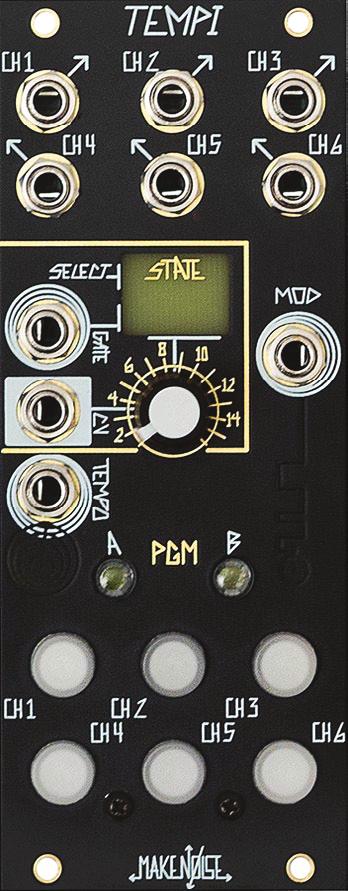
7 TEMPI Panel Controls 1. CHannel 1 OUTput 13. PGM_B BUTTON/ LED 2. CHannel 2 OUTput 14. CHannel BUTTON-1 / LED 3. CHannel 3 OUTput 15. CHannel BUTTON-2 / LED 4. CHannel 4 OUTput 16. CHannel BUTTON-3 / LED 5. CHannel 5 OUTput 17. CHannel BUTTON-4 / LED 6. CHannel 6 OUTput 18. CHannel BUTTON-5 / LED 7. STATE SELECT GATE INput 19. CHannel BUTTON-6 / LED 8. STATE SELECT CV INput 20. STATE LED 9. SELECT CV Attenuator/Combo Pot 21. MOD GATE INput 10. External TEMPO INput 11. TEMPO LED 12. PGM_A BUTTON / LED 22. MOD LED
8 7 TEMPI, BANK A and new Clock Divider/Multiplier settings. All these settings are user-editable and can be overwritten at will. Here's a short description: STATE 1 All six CHannels are 1. This setting is also the "Init" for all STATES in the other three BANKS. STATES 2-7 are Clock Divider States: 2. Powers of 2: 1, 2, 4, 8, 16, Primes: 2, 3, 5, 7, 11, Integers: 1, 2, 3, 4, 5, 6 5. Evens: 2, 4, 6, 8, 10, Odds: 3, 5, 7, 9, 11, Fibonacci: 2, 3, 5, 8, 13, 21 STATES 8-13 are Clock Multiplier States: 8. Powers of 2: *1, *2, *4, *8, *16, *32 9. Primes: *2, *3, *5, *7, *11, * Integers: *1, *2, *3, *4, *5, *6 11. Evens: *2, *4, *6, *8, *10, * Odds: *3, *5, *7, *9, *11, * Fibonacci: *2, *3, *5, *8, *13, * Multiples and Divisions: *2, *3, *4, 2, 3, PHASE Demonstration: All six CHannels are set to the same TEMPO, but with six unique Phase values. 16. Non-Integer Division Demonstration: Each successive channel is one Fine decrement slower than the previous, resulting in adjacent CHannels going slowly in and out of Phase with each other. The Factory Settings of the {ProGraM Edit} Page are as follows: - HUMAN Resolution 50% - SHIFT = CW - RUN/STOP = OFF - SHIFT = Jumbled
9 8 QUICK REFERENCE: MACHINE ProGraMming HUMAN ProGraMming [TAP] BUTTON1-6 at least twice HUMAN ProGraMming of MULTIPLE and DIVISIONS of Leading TEMPO VARIABLE CLOCK MULTIPLIER / DIVISOR {PHASE} [PRESS] PGM_A + PGM_B; PGM_A + PGM_B = <ON> [HOLD] PGM_A + [PRESS] CHannel BUTTON1-6 n times for VARIABLE CLOCK DIVISOR Coarse adjustment (1 n) [HOLD] PGM_B + [PRESS] CHannel BUTTON1-6 n times for VARIABLE CLOCK MULTIPLIER Coarse adjustment (1*n) [HOLD] CHannel BUTTON1-6 + [PRESS] PGM_A for VARIABLE CLOCK FINE Decrement [HOLD] CHannel BUTTON1-6: +[PRESS] PGM_A n times to PHASE Fine Decrement MULTIPLIER/DIVISOR value +[PRESS] PGM_B n times to PHASE Fine Increment MULTIPLIER/DIVISOR value [HOLD] PGM_A + [TAP] CHannel BUTTON1-6 to PHASE Coarse Decrement MULTIPLIER/DIVISOR [HOLD] CHannel BUTTON1-6 + [PRESS] PGM_B for VARIABLE CLOCK FINE Increment [HOLD] PGM_B + [TAP] CHannel BUTTON1-6 to PHASE Coarse Increment MULTIPLIER/DIVISOR {MUTE} [PRESS] PGM_A ; PGM_A= <ON> [PRESS] CHannel BUTTON1-6 to MUTE CHannels; MUTEd CHannels = <RED> {MOD} [PRESS] PGM_B ; PGM_B = <ON> [PRESS] CHannel BUTTON1-6 to MOD CHannels; MODded CHannels = <PURPLE> {STATE EDIT} [HOLD] both PGM_A + PGM_B: [PRESS] BUTTON-1 to RECALL current STATE [PRESS] BUTTON-2 to STORE current STATE [PRESS] BUTTON-3 to RECALL current BANK [PRESS] BUTTON-4 to COPY selected STATE [PRESS] BUTTON-5 to PASTE over selected STATE [PRESS] BUTTON-6 to MUTATE over selected STATE
10 QUICK REFERENCE: ( CONT'D ) {BANK EDIT} [DOUBLE PRESS] PGM_A; PGM_A = <FLASHING> [PRESS] BUTTON-1 to SELECT BANK [PRESS] BUTTON-2 to STORE ALL BANKS and current TEMPO [PRESS] BUTTON-3 to FOLLOW SELECT & TEMPO Busses [PRESS] BUTTON-4 to COPY selected BANK [PRESS] BUTTON-5 to PASTE over selected BANK [PRESS] BUTTON-6 to MUTATE over selected BANK [PRESS] PGM_A to Exit {BANK EDIT} {ProGraM EDIT} [DOUBLE PRESS] PGM_B; PGM_B = <FLASHING> MOD SETTINGS [PRESS] BUTTON-1 for HUMAN Resolution 100% [PRESS] BUTTON-2 for HUMAN Resolution 50% [PRESS] BUTTON-3 for HUMAN Resolution 25% [PRESS] BUTTON-4 for SHIFT: CW = <RED> CCW = <BLUE> RANDOM = <PURPLE> OFF = BUTTON-5 selected [PRESS] BUTTON-5 for RUN/STOP: RUN/STOP = <RED> RUN/STOP ALL = <BLUE> ALT RUN = <PURPLE> OFF = BUTTON-4 is [PRESSED] [PRESS] BUTTON-6 When SHIFT is active, sets behavior of SHIFT: NOT Jumbled SHIFT = <OFF> ; Jumbled SHIFT = <RED> When RUN/STOP is active, sets behavior of the MOD INput: Momentary = <RED>; Toggled = <OFF> 9
11 10 Leading TEMPO There are three ways to determine the Leading TEMPO, which synchronize the six, Variable Clock OUTputs of the TEMPI: 1. With nothing patched to the TEMPO INput, the last-stored TEMPO is used (refer to {BANK EDIT} page STORE, described on page 23). 2. When an External Clock is patched to the TEMPO INput, the External Clock source is followed. 3. When an internally-connected bus line is used via the TEMPO BUS, the generated Clock signal is FOLLOWed (refer to {BANK EDIT} page FOLLOW, described on page 25 ). Note: While externally clocking, when changing TEMPO from fast to slow, there will be some delay, as the TEMPI needs a minimum of 2 Clock pulses to measure the incoming Clock rate and lock into sync. If synchronizing TEMPI to DAW project, include 2 bars of silence, with sync clock running, at beginning of composition so TEMPI is locked into sync when composition starts. It is possible to [TAP] the TEMPO by patching a GATE OUTput, for example, from the Pressure Points, to TEMPI s TEMPO INput and [TAPPING] the desired TEMPO on the Pressure Points. Remember: at least two [TAPS] are required. The TEMPI will lock on to the new TEMPO and FOLLOW until a new TEMPO is [TAPPED]. TEMPO is indicated by the <BLUE> TEMPO LED that <FLASHES> just below the TEMPO INput jack. To ProGraM Leading TEMPO via [TAPPING]: Variable Clock ProGraMming: The Variable Clock OUTputs may be MACHINE ProGraMmed by [PRESSING] and [HOLDING] some combination of PGM_A or PGM_B and/or BUTTON(s)1-6 for the associated CHannel OUTputs. The Variable Clock OUTputs are MULTIPLES or DIVISIONS of the Leading TEMPO. When Variable Clock OUTs are active and MUTE disabled and/or MOD disabled, the associated CHannel BUTTON LED(s) are <BLUE>, <FLASHING> to indicate Clock High/Low. NOTE: Pulse Width of the Variable Clock OUTputs is always 50% Duty Cycle.
12 There are two ways to ProGraM Variable Clocks: MACHINE and HUMAN. 11 HUMAN ProGraMming HUMAN Clock ProGraMming combines MULTIPLIER/DIVISOR and PHASE settings into one simple, tactile process. For HUMAN ProGraMming, patch the Leading TEMPO (i.e. MULT of the clock patched to TEMPO INput or any CHannel TEMPI set to 1:1 using MACHINE MULTIPLIER or DIVISOR) so that the timing is audible, and ProGraM a Variable Clock by [TAPPING] the BUTTON(s)1-6 for the associated CHannel OUTput(s) in order to complement the Leading TEMPO, resulting in either a MULTIPLE or DIVISION of the Leading TEMPO. Notice, the User must [TAP] BUTTON at least twice in order to ProGraM a timing value. Changes happen as soon as algorithmically possible. Previous values for a given CHannel are overwritten as soon as associated BUTTON1-6 is [TAPPED] the second time. While HUMAN ProGraMming, STATE changes are ignored. For HUMAN ProGraMming: It is also possible to ProGraM several CHannels at once. This makes it more intuitive to create interesting timing arrangements. IMPORTANT: these changes ARE NOT STOREd UNTIL you STORE the STATE. Without running the STORE operation, changes ARE NOT held when the power is cycled. This makes it easy to improvise with alternate versions of a STOREd theme. [TAP] Associated BUTTON(s)1-6 RESOLUTION HUMAN ProGraMming has three levels of Resolution, determined by the ProGraMming of {ProGraM Edit} Page (to access, [DOUBLE PRESS] PGM_B = PGM_B <FLASHES>). The Resolution of HUMAN ProGraMming determines how the Variable Clocks are related to the Leading TEMPO s PHASE and MULTIPLIER/DIVISOR. The Resolution setting is indicated by ONE of these three BUTTON1-3 LEDs = <ON> while in {ProGraM Edit}: HUMAN Resolution 100% Results in the strictest relationships. This is the same as MACHINE ProGraMming Coarse MULTIPLIER/DIVISOR and PHASE adjustments (see "MACHINE" section). HUMAN Resolution 50% The Default setting, allowing for something less strict than 100%, but easier to use than 25%. HUMAN Resolution 25% Establishes in the most free relationships and in theory is the equivalent as MACHINE ProGraMming Fine MULTIPLIER/DIVISOR and PHASE adjustments.
13 12 MACHINE ProGraMming There are two types of MACHINE ProGraMming: Variable Clock MULTIPLIER/DIVISOR and PHASE. Variable Clock MULTIPLIER/DIVISOR ProGraMming requires a combination of [HOLDS] and [PRESSES] in order to adjust the associated Variable Clock OUTputs: For Variable Clock DIVISOR Coarse adjustment: The user [HOLDS] PGM_A and [TAPS] the desired CHannel BUTTON(s) one to thirty-two times in order to ProGraM the associated Variable Clock OUTput(s). NOTE: it s possible to [TAP] BUTTON(s)1-6 simultaneously, in order to ProGraM several CHannels at once. The TEMPI counts the [TAPS] and sets this number as the DIVISOR value. If thirty-two [TAPS] are exceeded, the count stays at maximum number of thirty-two-- the counting of subsequent [TAPS] is stops with changes take PGM_A is [RELEASED]. The STATE LED <LIGHTS RED> to indicate a Variable Clock DIVISOR Coarse adjustment. Previous values for a given CHannel are overwritten as soon as associated BUTTON(s)1-6 is [PRESSED] while [HOLDING] PGM_A. + [HOLD] PGM_A [TAP] Associated CHannel Button(s) 1-32 times To return to a 1:1 relationship with TEMPO (Default), [HOLD] PGM_A or PGM_B and [PRESS] associated CHannel BUTTON1-6 once. For Variable Clock MULTIPLIER Coarse adjustment: The user [HOLDS] PGM_B and [TAPS] the desired CHannel BUTTON(s) one to thirty-two times in order to ProGraM the associated Variable Clock OUTput(s). NOTE: it s possible to [TAP] BUTTON(s)1-6 simultaneously, in order to ProGraM several CHannels at once. The TEMPI counts the number of [TAPS] and sets this as the MULTIPLIER value. If thirty-two [TAPS] are exceeded, the count stays at maximum number of thirty-two-- the counting of subsequent [TAPS] is stopped PGM_B is [RELEASED]. The STATE LED <LIGHTS GREEN> to indicate a Variable Clock MULTIPLIER Coarse adjustment. Previous values for a given CHannel are overwritten as soon as the associated BUTTON(s)1-6 is [PRESSED] while [HOLDING] PGM_B. + [HOLD] PGM_B [TAP] Associated CHannel Button(s) 1-32 times To return to a 1:1 relationship with TEMPO (Default), [HOLD] PGM_A or PGM_B and [PRESS] associated CHannel BUTTON1-6 once.
14 MACHINE ProGraMming MULTIPLIER/DIVISOR: (cont d) 13 For Variable Clock MULTIPLIER/DIVISOR Fine adjustment: [PRESS] PGM_A to Variable Clock Fine decrement + [HOLD] Associated BUTTON(s)1-6 For Variable Clock Fine decrement (i.e. to make slower), the user [HOLDS] associated CHannel BUTTON1-6 and [PRESSES] PGM_A. The STATE LED <FLASHES RED> to indicate a Variable Clock Fine decrement has been made. or [PRESS] PGM_B to Variable Clock Fine increment For Variable Clock Fine increment (i.e. to make faster), the user [HOLDS] associated CHannel BUTTON1-6 and [PRESSES] PGM_B. The STATE LED <FLASHES GREEN> to indicate a Variable Clock Fine increment has been made. You may Fine increment or decrement across the entire possible Variable Clock much easier to make a Coarse adjustment and then make Fine adjustments
15 14 MACHINE ProGraMming {PHASE}: The other way to MACHINE ProGraM is by PHASE adjustments. To enter {PHASE} ProGraMming Page, [PRESS] both PGM_A and PGM_B at the same time. While in the {PHASE} page, both PGM_LEDs are <ON> and STATE changes and HUMAN ProGraMming are ignored. [PRESS] both PGM_A and PGM_B to exit {PHASE} ProGraMming Page. To begin {PHASE} ProGraMming, [PRESS] PGM_A and PGM_B Next, PHASE adjustments are performed in a similar way to the MULTIPLIER/DIVISOR settings, using Coarse and Fine PHASE decrements/increments. Once in {PHASE} ProGraMming Page: For Coarse PHASE decrement: For Coarse PHASE increment: [HOLD] PGM_A [HOLD] PGM_B [TAP] Associated BUTTON(s)1-6 one to four times [TAP] Associated BUTTON(s)1-6 one to four times + The user [HOLDS] PGM_A and [TAPS] CHannel BUTTON(s)1-6, one to four times in order to ProGraM the associated CHannel OUTput(s). Coarse PHASE adjustments offsets the PHASE of the CHannel's OUTput by one cycle of the Leading TEMPO. The STATE LED <LIGHTS RED> to indicate a Coarse PHASE decrement has been made. + The user [HOLDS] PGM_B and [TAPS] CHannel BUTTON(s)1-6, one to four times in order to ProGraM the associated CHannel OUTput(s). Coarse PHASE adjustments offset the PHASE of the CHannel's OUTput by one cycle of the Leading TEMPO. The STATE LED <LIGHTS GREEN> to indicate a Coarse PHASE increment has been made. When programming Multiples of the TEMPO, Coarse PHASE adjustments can be very subtle. Here is why: if the CHannel is set to an integer Multiple (e.g. * 4), Coarse PHASE will have no audible effect, because the CHannel's Clocks are output at the same times at each pulse of the TEMPO. If the CHannel is set to a non-integer Multiple (e.g. * 4.25), the CHannel's clocks will drift in and out of PHASE with the TEMPO over a period of several pulses of the TEMPO. Coarse PHASE of a Multiple in this situation will only affect the zero-center of this PHASE-shifting: a subtle effect indeed.
16 15 MACHINE ProGraMming {PHASE}: (cont d) While still in {PHASE} ProGraMming Page: For Fine PHASE adjustment: [HOLD] Associated BUTTON(s)1-6 [PRESS] PGM_A to Fine PHASE decrement (i.e. lead AHEAD of TEMPO) + or [PRESS] PGM_B to Fine PHASE increment (i.e. lag BEHIND TEMPO) ProGraMmed to be quarter of a cycle of the PHASE, Fine PHASE adjustments For FINE PHASE decrement, the user [HOLDS] the associated CHannel BUTTON(s)1-6 and [PRESSES] PGM_A. The STATE LED <FLASHES RED> to indicate a FINE PHASE decrement has been made. For FINE PHASE increment, the user [HOLDS] the associated CHannel BUTTON(s)1-6 and [PRESSES] PGM_B. The STATE LED <FLASHES GREEN> to indicate a FINE PHASE increment has been made. For CHannels PHASE of the CHannel's OUTput by one Leading TEMPO Coarse PHASE adjustments OVERRIDE Fine PHASE adjustments. In this way, Coarse PHASE adjustments return to INTEGRAL DIVISORS and MULTIPLIERS, for instance, 1:1.
17 {MUTE} 16 To MUTE a CHannel output, [PRESS] PGM_A to toggle {MUTE} ProGraM page to "ON." In order to exit the {MUTE} ProGraM page, [PRESS] PGM_A. The associated PGM_A LED <ON> indicates that the {MUTE} ProGraM page is active. While in {MUTE} page, STATE changes are ignored. The User then [PRESSES] the associated CHannel BUTTON(s)1-6 in order to toggle the Variable Clock OUTput(s) to be MUTE enabled or MUTE disabled. When toggled to be MUTE enabled, the associated BUTTON1-6 LED is <RED> and <FLASHES> with each Rising Edge of each Clock in order to indicate the currently ProGraMmed Variable Clock. If toggled to be MUTE disabled, the associated CHannel BUTTON1-6 is <BLUE>. If a CHannel is MOD enabled and MUTE disabled, the associated CHannel BUTTON1-6 is <PURPLE>. Alternatively, if a CHannel is BOTH MOD enabled and MUTE enabled (see below), the associated CHannel BUTTON1-6 LED(s) is <PINK>. The purpose of {MUTE} is to stop the Clock activity at the associated CHannel OUT(s) while still allowing the user to ProGraM desired changes. In this way, it is possible to ProGraM a new Variable Clock into a MUTE enabled CHannel. This is useful for cueing changes during live performance. Exit the {MUTE} page by [PRESSING] PGM_A in order to ProGraM changes to the MUTED CHannel by MACHINE or HUMAN ProGraMming. MUTE enabled, = MOD disabled <RED> MUTE disabled, = MOD disabled <BLUE> MUTE disabled, = MOD enabled <PURPLE> MUTE enabled = and MOD enabled <PINK> NOTE: It is possible to {MUTE} ProGraM several CHannels at once. This makes it more intuitive to create interesting timing arrangements. Please note: these changes ARE NOT STOREd UNTIL you STORE the STATE. Without running the STORE operation, changes ARE NOT held when the power is cycled. This is useful for improvising with alternate versions of a STOREd theme.
18 {MOD} 17 The MOD function allows you to ProGraM SHIFT or RUN/STOP behavior. To ProGraM the MOD function, [PRESS] PGM_B to toggle to {MOD} ProGraM page, indicated by the PGM_B LED <ON>. While in {MOD} page, STATE changes are ignored. In order to exit the {MOD} ProGraM page, [PRESS] PGM_B again. In order to toggle associated Variable CLocK OUTput(s) to be in or out of the MOD function, [PRESS] the associated CHannel BUTTON(s)1-6. CHannels in the MOD function are <PURPLE> and <FLASH> to indicate the currently ProGraMmed Variable Clock. If a CHannel is BOTH MOD and MUTE enabled, the associated CHannel LED appears <PINK>. If a CHannel is MOD disabled, it is either <BLUE> or <RED>. ALL CHannels will continue to <FLASH> to indicate currently-programmed Variable Clock. MOD disabled, MUTE enabled = <RED> MOD disabled, MUTE disabled = <BLUE> MOD enabled, MUTE disabled = <PURPLE> MOD enabled and MUTE enabled = <PINK> {ProGraM EDIT} [DOUBLE PRESS] PGM_B: MOD SETTINGS [PRESS] BUTTON4 for SHIFT: CW CCW RANDOM OFF = = = = <RED> <BLUE> <PURPLE> BUTTON-5 selected [PRESS] BUTTON5 for RUN/STOP RUN/STOP RUN/STOP ALL ALT RUN OFF = <RED> = <BLUE> = <PURPLE> = BUTTON-4 selected [PRESS] BUTTON-6 When SHIFT is active (i.e. BUTTON-4 = <ON>), sets Jumbled SHIFT ON/OFF; <RED> = OFF While HUMAN or MACHINE ProGaMming, MOD remains disabled until ProGaMming is completed. This behavior may be used creatively in order to manually "freeze" the MOD functionality. In order to easily create interesting timing arrangements, it is possible to MOD ProGraM several CHannels at once. The MOD function is determined by the ProGraMming of the MOD SETTINGS in the {ProGram EDIT} page. The MOD IN TEMPI according to the SHIFT, which causes timing information to move between MOD-enabled CHannels at each new Gate, and RUN/STOP, which can cause some or all CHannels to RUN, STOP, and/or RESET. The MOD LED will <FLASH MAGENTA> to indicate a MOD function has been performed. When RUN/STOP is active (i.e. BUTTON5 = <ON>), sets behavior of the MOD INput jack to be Momentary or Toggled; <RED> = OFF Please note: these changes ARE NOT STOREd UNTIL you STORE the STATE. Without running the STORE operation, changes ARE NOT held when the power is cycled. This is useful for improvising with alternate versions of a STOREd theme.
19 18 {ProGraM EDIT}: SHIFT The SHIFT FUNction trades the values for the Variable Clock OUTputs and is accessed from the {ProGraM EDIT} page ([DOUBLE PRESS] PGM_B = PGM_B <FLASHES>). For example, if CHannels 2, 3, and 5 are set to be SHIFTed, on the Rising Edge of each Gate in the MOD INput, the value of Variable Clock 2 is swapped with that of Variable Clock 5, while simultaneously replacing the value of Variable Clock 3 with that of the previous Variable Clock 2, allowing CHannel 5 to take on the original value of CHannel 3. In other words, it behaves as a Shift Register for the Variable Clock parameter values, where at each SHIFT command received, the values are passed to the next active CHannel within the {MOD} Page. These changes always occur at the Rising Edge of the signal patched to the MOD INput so that when a Gate "HIGH" is read, the MOD LED <FLASHES MAGENTA> and the SHIFT of parameter values occurs immediately, thus allowing for self-patching the TEMPI. Using BUTTON-6 in {ProGraM EDIT}, SHIFT may be ProGraMmed to operate in the following two ways when the user navigates away from and back to a State: Not-Jumbled SHIFT is the Default and goes back to the last STOREd settings; BUTTON-6 LED = <OFF> Jumbled SHIFT returns to the values last utilized at that STATE; BUTTON-6 LED = <RED> Disengage JUMBLED SHIFT when you want to easily return to a STATE's ProGraMmed Variable Clocks even after having SHIFTed any number of CHannels.Note: MUTEs are not SHIFTed. One could emulate a SHIFTed MUTE by ProGraMming a large Division and SHIFTing. Tip: SHIFT is also useful for ProGraMming variations of STATEs where you want use the same TEMPI CHannels: 1. Create your initial STATE. 2. COPY and then PASTE to another STATE. 3. [PRESS] PGM_B to enter {MOD} ProGraMming Page and set two CHannels to be SHIFT Enabled (BUTTON1-6 = <Purple>) 4. Send a Gate signal to the MOD INput to swap. 5. Set these two CHannels back to being MOD disabled. Use this technique to trade CHannel values and create new STATEs. Using BUTTON-4 in {ProGraM EDIT}, SHIFT may be ProGraMmed to operate in the following directions: Clockwise, CW BUTTON-4 = <Red> Counterclockwise, CCW BUTTON-4 = <Blue> Random (aka RODENT Mode) OFF BUTTON-4 = <Purple> BUTTON-4 = <OFF> when BUTTON-5 is [ON]
20 19 {ProGraM EDIT}: RUN / STOP The RUN / STOP FUNction allows for modulating the phase relationship, resting and/or resetting the Variable Clock OUTputs. When RUNning, the Variable Clock OUTputs are ON and operate as ProGraMmed with a 50% Duty Cycle Clock signal. When STOPpedthe Variable Clock OUTputs are resting at 0V, or OFF. There are several types of RUN/STOP behaviors to choose from that are ProGraMmed using BUTTON-5 in the {ProGraM EDIT} Page ([DOUBLE PRESS] PGM_B = PGM_B <FLASHES>): RUN / STOP BUTTON-5 = <Red> RUN / STOP ALL BUTTON-5 = <Blue> ALT RUN / STOP BUTTON-5 = <Purple> OFF BUTTON-5 = <OFF> when BUTTON-4 = <ON> RUN / STOP BUTTON-5 = <RED> Makes CHannels ProGraMmed for MOD = <Purple>, RUN on MOD <ON>, and STOP on MOD <OFF>. RUN Starts the channel immediately, regardless of phase relationship to the input tempo, and preserves that PHASE OFFSET until STATE change, HUMAN or MACHINE programming or STOP. This allows for external modulation of a CHannel's PHASE relationaship to the Leading TEMPO. CHannels not ProGraMmed for MOD= <PURPLE> are NOT affected. The MOD LED indicates if the MOD is <ON> or <OFF> If signal patched to MOD IN is an integer of the LEADING TEMPO (1/1, 1/2, 1/4, 2/1 and etc...), RUN/ STOP may also be used to RESET a CHannel. RUN / STOP ALL (aka James Cigler Mode) BUTTON-5 = <BLUE> Makes all CHannels RUN on MOD <ON> and STOP on MOD <OFF>, reseting all CHannels on RUN. The MOD LED indicates if the MOD is <ON> or <OFF>. CHannels ProGraMmed for MOD = <PURPLE> start immediately, regardless of phase relationship to the INput Tempo, and preserve that PHASE OFFSET until STATE change, HUMAN or MACHINE programming or STOP. CHannels NOT ProGraMmed for MOD = <PURPLE>. Start in phase with Leading Tempo. This behavior is good for creating compositional structures where you would like a Beginning or End. If synchronizing TEMPI to DAW project, include 2 bars of silence, with sync clock running, at beginning of composition so TEMPI is locked into sync when composition starts and TEMPI receives RUN signal, MOD = <ON>. RUN/ STOP ALL is also nice when used with a MIDI to CV module to convert MIDI Note On/Note Off messages to Gate Signals that may be used to drive the TEMPI. ALT. RUN / STOP (aka Robert A.A. Lowe Mode) BUTTON-5= <PURPLE> Makes CHannels ProGraMmed for MOD = <PURPLE>, RUN on MOD <ON> while CHannels not ProGraMmed for MOD <BLUE> will STOP on MOD <ON> and vice versa. The MOD LED indicates if the MOD is <ON> or <OFF>. Starts channels immediately, regardless of phase relationship to the INput Tempo, and preserves that PHASE OFFSET until STATE change, HUMAN or MACHINE programming or STOP. This allows for external modulation of a CHannel's PHASE relationaship to the Leading TEMPO. If signal patched to MOD IN is an integer of the LEADING TEMPO (1/1, 1/2, 1/4, 2/1 and etc...), may also be used to RESET a CHannel, and maintain phase with Leading TEMPO. OFF BUTTON-5 = <OFF>, when BUTTON-4 is <ON>
21 20 {ProGraM EDIT}: RUN / STOP (cont d) Still in the {ProGraM EDIT} Page ([Double Press] PGM_B = PGM_B <FLASHES>), while RUN / STOP is active (i.e. BUTTON-5 = <ON>, any color), BUTTON-6 sets the behavior of the MOD IN jack to be Momentary or Toggled. Momentary BUTTON-6 = <Red> Toggled BUTTON-6 = <OFF> Momentary BUTTON-6 =<RED> Makes the RUN / STOP behavior mirror that of the MOD Gate INput. When the MOD Gate INput is "High," MOD is ON. Alternatively, when the MOD Gate INput is "Low," MOD is OFF. Toggled BUTTON-6 = <OFF> Makes the RUN / STOP behavior turn <ON> and RUN when MOD Gate INput goes "High" and not turn OFF and/or STOP until the MOD Gate INput goes from "Low" to "High" a second time. The MOD LED <LIGHTS MAGENTA> at the rising edge of the signal in the MOD Gate INput.
22 21 {STATE EDIT}: STATES TEMPI stores up to sixty-four timing scenarios referred to as STATES, arranged into four BANKS of sixteen, with the STATE LED that indicates BANK by <COLOR> and STATE changes by <FLASHING>. STATE is selected by either STATE SELECT CV or GATE, with STATE SELECT CV having top priority. The STATE SELECT GATE increments the STATE value at the rising-edge of each Gate. In other words, when a STATE change is read at STATE SELECT CV, that change is absolute and takes priority over STATE SELECT GATE changes. There is a Gate INput for STATE SELECT GATE and a Combo Pot/CV INput for STATE SELECT CV. With nothing patched to STATE SELECT CV INput, the STATE SELECT CV Combo Pot operates as a Panel Control which manually selects the STATE. The STATE SELECT CV Range is 0V to 5V. The STATE LED above the STATE SELECT CV Panel Control <FLASHES> each time STATE is changed. To RESET to STATE 1, patch a Gate to the STATE SELECT CV INput and set the Combo Pot/attenuator so at GATE HIGH, TEMPI goes to the last STATE you would like to use (STATE 8, for example). Next, patch a Clock or Gate to the STATE SELECT GATE INput and step through STATES 1 through 8. Send a RESET GATE to the STATE SELECT CV INput and at GATE LOW, you will return to STATE 1. In this way, it is possible to sequence any number of STATES linearly from STATE 1 to STATE n before RESETting. While {MUTE}, {MOD}, {HUMAN}, {MACHINE}, or {PHASE} ProGraMming are active, STATE is held and DOES NOT This behavior may be used creatively in order to manually "freeze" the MOD functionality or STATE SELECT modulation. To STORE or RECALL a STATE: [HOLD] PGM_A + PGM_B [PRESS] BUTTON-1 to RECALL current STATE or + [PRESS] BUTTON-2 to STORE current STATE or [PRESS] BUTTON-3 to RECALL current BANK from Memory Note: {STATE EDIT} settings are saved on STATE STORE.
23 22 {STATE EDIT}: COPY, PASTE, and MUTATE STATE Use STATE SELECT Panel Control in order to audition and select a STATE to COPY. Note: it is important that you STATE SELECT and/or MOD in order to accurately choose the STATE, [HOLD] both PGM_A + PGM_B and [PRESS] BUTTON-4 to desired STATE COPY. After a STATE is COPIED, you may then decide to PASTE an exact duplicate or a MUTATEd version of the COPIED STATE. Once COPIED, use the STATE SELECT Panel Control in order to audition and select a STATE into which you would like to PASTE. Keep in mind, you will be overwriting what is STOREd in the currently-selected STATE! To PASTE operation, [HOLD] PGM_A and PGM_B and [PRESS] BUTTON-5. Alternatively, once a STATE has been COPIED, you may use the STATE SELECT Panel Control in order to select a STATE over which you would like to paste a MUTATEd copy. MUTATE is very similar to the PASTE operation, so keep in mind, you will be overwriting what is STOREd in the currently-selected STATE! STATE to overwrite, [HOLD] both PGM_A + PGM_B and [PRESS] BUTTON-6 in order to paste a MUTATEd version of the previously-copied STATE. MUTATE works by deviating to a small degree from the values that are already ProGraMmed within a COPIED STATE. To create more dramatic and alarming Mutations, simply, repeat the COPY and MUTATE procedures again and again. Note: is possible to COPY, PASTE, and MUTATE several times to quickly and easily ProGraM a STATE or BANK. Please note that these changes ARE NOT STOREd UNTIL you STORE the STATE or BANK. Without running the STORE operation, changes ARE NOT held after power is cycled. This is useful for improvising alternate versions of a STOREd theme. To COPY, PASTE, or MUTATE a STATE: [HOLD] PGM_A + PGM_B [PRESS] BUTTON-4 to COPY a STATE or + [PRESS] BUTTON-5 to PASTE a previously-copied STATE or [PRESS] BUTTON-6 to MUTATE a previously-copied STATE
24 23 {BANK EDIT} Settings In order to enter {BANK EDIT} ProGraMming page, [DOUBLE PRESS] PGM_A. PGM_A <FLASHES> in order to indicate {BANK EDIT} page. To exit the {BANK EDIT} ProGraMming page, [DOUBLE PRESS] PGM_A. {BANK EDIT} [DOUBLE PRESS] PGM_A: [PRESS] BUTTON-1 to SELECT BANK [PRESS] BUTTON-2 to STORE ALL BANKS and current TEMPO [PRESS] BUTTON-3 to FOLLOW SELECT & TEMPO Busses [PRESS] BUTTON-4 to COPY selected BANK [PRESS] BUTTON-5 to PASTE over selected BANK [PRESS] BUTTON-6 to MUTATE over selected BANK [PRESS] PGM_A to Exit {BANK EDIT} SELECT BANK: In order to SELECT BANK, within the {BANK EDIT} ProGraMming page (to access, [DOUBLE PRESS] PGM_A = PGM_A <FLASHES>) and [PRESS] BUTTON-1 for sequential selection of BANK1, BANK2, BANK3, or BANK4. The STATE LED BANK1 = <Blue> BANK change as follows: BANK2 = <Amber> BANK3 = <Pink> BANK4 = <White> (LED Colors May Vary) STORE ALL BANKS: In order to STORE all contents of all BANKS (i.e. ALL STATEs and Leading TEMPO), within the {BANK EDIT} ProGraMming page (to access, [DOUBLE PRESS] PGM_A = PGM_A <FLASHES>), [PRESS] BUTTON-2. The STATE LED <FLASHES RED> in order to indicate STORE complete. [DOUBLE PRESS] PGM_A + [PRESS] BUTTON-2 to STORE ALL BANKS
25 24 {BANK EDIT} Settings (CONT d) COPY, PASTE, and MUTATE BANKS: Still in the {BANK EDIT} ([DOUBLE PRESS] PGM_A = PGM_A <FLASHES>) page, in order to COPY, [PRESS] BANK, [PRESS] BUTTON-4 to COPY. BUTTON-1 to select the BANK to COPY In order to PASTE, [PRESS] BUTTON1 to select the BANK into which you would like to PASTE. Keep in mind: you will be overwriting what is STOREd in the selected BANK! Lastly, [PRESS] BUTTON-5 to complete the PASTE operation. MUTATE works by deviating to a small degree from the values that are already ProGraMmed within a COPIED BANK. In order to MUTATE a COPIED BANK [DOUBLE PRESS] PGM_A to migrate to the {BANK EDIT} ProGraMming page. Next, [PRESS] BUTTON-1 to select the desired BANK to MUTATE desired BANK, [PRESS] BUTTON-6 in order to paste a MUTATEd copy. To create more dramatic and alarming mutations, simply repeat the COPY and MUTATE procedures again and again. Note: it is possible to COPY, PASTE, and MUTATE several times to quickly and easily ProGraM a BANK. MUTATING a CHannel that is ProGraMmed with a 1:1 MULTIPLE or DIVISOR Variable Clock value will have very little To COPY, PASTE, or MUTATE a BANK: [PRESS] BUTTON-1 to SELECT BANK [DOUBLE PRESS] PGM_A or [PRESS] BUTTON-4 to COPY selected BANK + or [PRESS] BUTTON-5 to PASTE over selected BANK or [PRESS] BUTTON-6 to MUTATE over selected BANK
26 25 {BANK EDIT} Settings (CONT d) FREE / FOLLOW In order to set the TEMPI to FOLLOW the TEMPO and SELECT Busses, [PRESS] BUTTON-3. The TEMPO LED is <GREEN> to indicate FOLLOW. [PRESS] BUTTON-3 again to set TEMPI to be FREE of the TEMPO and SELECT Busses, indicated by the <BLUE> TEMPO LED. FREE TEMPO LED = <BLUE> FOLLOW TEMPO LED = <GREEN> While set to FOLLOW, the TEMPI RECEIVES messages from the SELECT Bus that help determine the STATE and a Clock from the TEMPO Bus to determine the Leading TEMPO. IT DOES NOT TRANSMIT messages. The Panel Controls for STATE and TEMPO are still useful when the TEMPI is set to FOLLOW. The STATE SELECT CV STATE that is selected by the SELECT Bus. The TEMPO Bus may be completely overridden by patching a Clock to the External TEMPO INput, thus allowing for an independent Leading TEMPO. Please note: changes ARE NOT STOREd UNTIL you go to {BANK EDIT} ProGraMming page and [PRESS] BUTTON-2 to STORE ALL BANKS. Without running the STORE ALL BANKS operation, changes are held ONLY UNTIL the power is cycled. This is useful for improvising alternate versions of a theme.
27 26 {BANK EDIT}: SELECT BUS and TEMPO Buses The SELECT Bus and TEMPO Bus utilize the often-inactive CV and GATE Busses in the Eurorack system in order to allow remote (i.e. patch-less) control of STATE SELECTion and TEMPO for TEMPI and other modules designed with this standard in mind. Any number of TEMPI on the same Bus Board can be controlled simultaneously by these signals, simplifying the process of macro-control over complex changes in a patch. It is worth noting, TEMPI only RECEIVES messages over the SELECT/TEMPO Buses. IT DOES NOT TRANSMIT. To engage Bus Control, enter {BANK EDIT} page ([DOUBLE-PRESS] PGM_A) and [PRESS] BUTTON-3. When the SELECT and TEMPO Busses are enabled, the TEMPO LED will <FLASH GREEN> instead of <BLUE>. Now, the TEMPI will be controllable by Clock and STATE SELECT signals coming through these Busses. SELECT and TEMPO Busses Disabled TEMPO LED = <BLUE> SELECT and TEMPO Busses Enabled TEMPO LED = <GREEN> Before engaging, make sure that no other modules are sending CV, Gate, or other signals (other than SELECT and TEMPO signals) through the Busses. More information regarding SELECT and TEMPO Buses will become available as the standard is developed.
28 Tips and Tricks 27 It is possible to ProGraM several CHannels at once. This makes it more intuitive to create interesting timing arrangements. This is true of MACHINE, HUMAN, MOD, MUTE, and PHASE ProGraMming. Coarse PHASE adjustments OVERRIDE Fine PHASE adjustments. In this way, Coarse Adjustments return to INTEGRAL DIVISORS and MULTIPLIERS, for instance, 1:1 ratio. MUTEs are not SHIFTed. One could emulated a SHIFTed MUTE by programming a large DIVISION and SHIFTing. For example, this allows for turning off a voice within a patch or stopping a sequence. You must first COPY a STATE or BANK before you can MUTATE it. If HUMAN ProGraMming and you would like to use only INTEGER Divisions or Multiples, set to Human Resolution 100% ([PRESS] Button-3 on {ProGraM EDIT} Page). This will ensure instantly perfect ProGraMming of four on the floor beats, or something similar. If using SHIFT, and changing STATES, turn JUMBLED SHIFT ON to preserve SHIFTed channels after leaving and returning STATES. This is useful for creating Live modifications to timing arrangements. This is also the default. If you would like to return SHIFTed channels to their original positions, turn JUMBLED SHIFT OFF and then leave and return to STATE. This is useful for creation Live modifications to timing arrangements without messing up the original settings. The STATE SELECT CV and Panel Control override any STATE stepping that occurs. So if you stepped through STATES with STATE SELECT Gate and then changed STATE SELECT Panel Control, it immediately takes it back to the Panel Control (or CV) setting. For example, if set to STATE 1 then STATE STEP six times with STATE SELECT Gate to STATE 6 and then turn the STATE SELECT Panel Control to STATE 2, the next STATE would be STATE 3, as the knob position and STATE SELECT CV takes priority when moving. It is possible to ProGraM a new Variable Clock into a MUTED CHannel. This is useful for cueing changes during live performance. The SHIFT Register function and MODded CHannels do not activate without a Trigger or Gate patched to the MOD Gate Input. For SHIFT, at least two CHannels must be MOD-enabled. If only one CHannel is MOD-enabled it can only SHIFT with itself (i.e. no visible effect). MUTATING a CHannel that is ProGraMmed with a 1:1 DIVISOR or MULTIPLE value will have very little effect. If a STATE or BANK is COPIED and then MUTATEd, it is still possible to PASTE an unmutated iteration of the associated STATE or BANK. To create more dramatic and alarming Mutations, simply, repeat the COPY and MUTATE procedures again and again. In this way, it is possible to COPY, PASTE, and MUTATE for easily ProGraMming a STATE or BANK. For a stable TEMPO, once the Leading TEMPO is learned, unpatch the Clock from the external TEMPO INput. As such, to create Clock Jitter, pre-process your External Clock before it is patched to the TEMPO INput. Even as the External Clock rate changes, the TEMPI s Variable Clock OUTputs will remain synchronized as long as the External Clock remains patched to the TEMPO INput. Self-patching the TEMPI's OUTputs to the MOD, STATE SELECT GATE INput, and even STATE SELECT CV INput can be very useful. However, be aware that self-patching to the TEMPO input will result in a feedback loop that causes the module to quickly reach maximum or minimum TEMPO value (unless the CHannel patched to TEMPO INput is set to 1:1, in which case it will have no effect at all). To RESET to STATE 1, patch a Gate to the STATE SELECT CV INput and set the Combo Pot/attenuator so at GATE HIGH, TEMPI goes to the last STATE you would like to use (STATE 8, for example). Next, patch a Clock or Gate to the STATE SELECT GATE INput and step through STATES 1 through 8. Send a RESET GATE to the STATE SELECT CV INput and at GATE LOW, you will return to STATE 1. In this way, it is possible to sequence any number of STATES linearly from STATE 1 to STATE n before RESETting.
TEMPI FCC Limited Warranty
 v2.7 2 TEMPI FCC ------------------------------------------------------------------3 Limited Warranty -------------------------------------------------4 Installation ----------------------------------------------------------5
Spiratone FCC: Limited Warranty:
 SpirA tone v. 2.3 1 Spiratone FCC: -------------------------------------------------------------------2 Limited Warranty: ----------------------------------------------------3 Installation: ---------------------------------------------------------4
Table of Contents: ECHOPHON
 v2.6 Table of Contents: 2 ECHOPHON FCC -----------------------------------------------------3 Limited Warranty ----------------------------------------4 Installation --------------------------------------------------5
Limited WARRANTY: Make Noise implies and accepts no responsibility for harm to person or apparatus caused through operation of this product.
 v2.5 2 BRAINS Limited Warranty ----------------------------------------------------3 Installation --------------------------------------------------4 Jumpers and Cable Connections --------------------------------5
Limited WARRANTY: Make Noise implies and accepts no responsibility for harm to person or apparatus caused through operation of this product.
 v2.4 1 BRAINS Limited Warranty: ----------------------------------------------------2 Installation: --------------------------------------------------3 Jumpers and Cable Connections: --------------------------------4
Pressure Points. v. 2.5
 Pressure Points v. 2.5 2 Pressure Points FCC-------------------------------------------------------------------3 Limited Warranty ----------------------------------------------------4 Installation ----------------------------------------------------5
WOGGLEBUG Limited Warranty Installation
 v2.5 2 WOGGLEBUG Limited Warranty ----------------------------------------------------3 Installation --------------------------------------------------4 Panel Controls --------------------------------------------------------5
ROSIE Limited Warranty Installation
 v2.3 2 ROSIE Limited Warranty -----------------------------------------------------3 Installation ----------------------------------------------------------------4 Panel Controls ---------------------------------------------------------------5
Limited WARRANTY: Make Noise implies and accepts no responsibility for harm to person or apparatus caused through operation of this product.
 Rosie Limited WARRANTY: Make Noise warrants this product to be free of defects in materials or construction for a period of one year from the date of purchase (proof of purchase/invoice required). Malfunction
Table of Contents. FCC Limited Warranty Installation
 Table of Contents 2 3 4 5 6 7 8 10 13 14 16 21 22 28 29 31 FCC Limited Warranty Installation Overview Getting Started with René Panel Controls and Inputs/Outputs Clocking René CV and Page Programming Grids
VARIGATE 4+ MANUAL V.1
 www.malekkoheavyindustry.com 814 SE 14TH AVENUE PORTLAND OR 97214 USA TABLE OF CONTENTS SPECIFICATIONS 1 INSTALLATION 2 DESCRIPTION 3 OVERVIEW 4-5 PROGRAMMING GATES PER STEP 6 PROGRAMMING CV/NOTES PER
Shifty Manual. Shifty. Voice Allocator Hocketing Controller Analog Shift Register Sequential/Manual Switch. Manual Revision:
 Shifty Voice Allocator Hocketing Controller Analog Shift Register Sequential/Manual Switch Manual Revision: 2018.10.14 Table of Contents Table of Contents Compliance Installation Installing Your Module
Written by Jered Flickinger Copyright 2019 Future Retro
 Written by Jered Flickinger Copyright 2019 Future Retro www.future-retro.com 2 TABLE OF CONTENTS Page 4 - Overview Page 5 Controls Page 6 Inputs and Outputs Page 7 MIDI Page 8 Jumper Settings Page 9 Standalone
QUAD ENVELOPE MANUAL V.1
 www.malekkoheavyindustry.com 814 SE 14TH AVENUE PORTLAND OR 97214 USA TABLE OF CONTENTS SPECIFICATIONS 1 INSTALLATION 2 DESCRIPTION 3 CONTROLS 4-6 MEASUREMENTS 7 USING QUAD ENVELOPE WITH VARIGATE 8+ AND
Please contact with any questions, needs & comments... otherwise go MAKE NOISE.
 soundhack ECHOPHON Limited WARRANTY: Make Noise warrants this product to be free of defects in materials or construction for a period of two years from the date of manufacture. Malfunction resulting from
QUAD LFO MANUAL V SE 14TH AVENUE PORTLAND OR USA
 www.malekkoheavyindustry.com 814 SE 14TH AVENUE PORTLAND OR 97214 USA TABLE OF CONTENTS SPECIFICATIONS 1 INSTALLATION 2 DESCRIPTION 3 CONTROLS 4-6 USING QUAD LFO WITH VARIGATE 8+ AND VARIGATE 4+ 7 WARRANTY
Polyend Poly Polyphonic MIDI to CV Converter User Manual
 Polyend Poly Polyphonic MIDI to CV Converter User Manual Made in Poland polyend.com Polyend Poly Polyphonic MIDI to CV Converter in the Eurorack format Poly is probably the easiest entry point for exploring
Revision 1.2d
 Specifications subject to change without notice 0 of 16 Universal Encoder Checker Universal Encoder Checker...1 Description...2 Components...2 Encoder Checker and Adapter Connections...2 Warning: High
ALGORHYTHM. User Manual. Version 1.0
 !! ALGORHYTHM User Manual Version 1.0 ALGORHYTHM Algorhythm is an eight-step pulse sequencer for the Eurorack modular synth format. The interface provides realtime programming of patterns and sequencer
FCC. to operate the equipment.
 v2.5 2 Table of Contents: Morphagene FCC------------------------------------------------------------------3 Limited Warranty-------------------------------------------------4 Installation----------------------------------------------------------5
Quad Clock Distributor (QCD) from 4ms Company
 from 4ms Company") Quad Clock Distributor (QCD) from 4ms Company Eurorack Module User Manual v1.0 (2013-12-09) The Quad Clock Distributor (QCD) from 4ms Company is a four channel Voltage Controlled Clock Divider/Multiplier
Quad Clock Distributor (QCD) from 4ms Company Eurorack Module User Manual v1.0 (2013-12-09) The Quad Clock Distributor (QCD) from 4ms Company is a four channel Voltage Controlled Clock Divider/Multiplier
Synthesis Technology E102 Quad Temporal Shifter User Guide Version 1.0. Dec
 Synthesis Technology E102 Quad Temporal Shifter User Guide Version 1.0 Dec. 2014 www.synthtech.com/euro/e102 OVERVIEW The Synthesis Technology E102 is a digital implementation of the classic Analog Shift
randomrhythm Bedienungsanleitung User Guide
 randomrhythm Bedienungsanleitung User Guide EN Foreword Whether random really exists or is just an illusion, shall be discussed by philosophers and mathematicians. At VERMONA, we found a possibility to
Shifty Manual v1.00. Shifty. Voice Allocator / Hocketing Controller / Analog Shift Register
 Shifty Manual v1.00 Shifty Voice Allocator / Hocketing Controller / Analog Shift Register Table of Contents Table of Contents Overview Features Installation Before Your Start Installing Your Module Front
NAVIGATOR OWNER S MANUAL
 OWNER S MANUAL UNCHARTED WATERS, NEW HORIZONS Making shapes spin and move is notoriously difficult for pattern synthesis based only on oscillators synchronized to horizontal and vertical frequency ranges.
Description. Never run out of envelopes again.
 Contour Description Never run out of envelopes again. Contour is a quad envelope generator. Each channel has looping, CV over attack and decay, as well as unique chaining capabilities. This makes for the
Rhythm. Pattern Generator
 Rhythm Pattern Generator Description The Rhythm is a 4 channel pattern generator with BPM display. It ships with a multitude of genre-oriented rhythms that can be altered on a per channel basis. With each
American DJ. Show Designer. Software Revision 2.08
 American DJ Show Designer Software Revision 2.08 American DJ 4295 Charter Street Los Angeles, CA 90058 USA E-mail: support@ameriandj.com Web: www.americandj.com OVERVIEW Show Designer is a new lighting
fxbox User Manual P. 1 Fxbox User Manual
 fxbox User Manual P. 1 Fxbox User Manual OVERVIEW 3 THE MICROSD CARD 4 WORKING WITH EFFECTS 4 MOMENTARILY APPLY AN EFFECT 4 TRIGGER AN EFFECT VIA CONTROL VOLTAGE SIGNAL 4 TRIGGER AN EFFECT VIA MIDI INPUT
// K4815 // Pattern Generator. User Manual. Hardware Version D-F Firmware Version 1.2x February 5, 2013 Kilpatrick Audio
 // K4815 // Pattern Generator Kilpatrick Audio // K4815 // Pattern Generator 2p Introduction Welcome to the wonderful world of the K4815 Pattern Generator. The K4815 is a unique and flexible way of generating
ADE-32 OCTOCONTROLLER
 ADE-32 OCTOCONTROLLER Control, Modulation, Triggering and Pattern module with 12 Output Types individually assignable to 8 simultaneous Outputs. USER GUIDE 2016 Abstract Data Ltd. http://www.abstractdata.biz
Noise Tools 1U Manual. Noise Tools 1U. Clock, Random Pulse, Analog Noise, Sample & Hold, and Slew. Manual Revision:
 Noise Tools 1U Clock, Random Pulse, Analog Noise, Sample & Hold, and Slew Manual Revision: 2018.09.13 Table of Contents Table of Contents Compliance Installation Before Your Start Installing Your Module
R H Y T H M G E N E R A T O R. User Guide. Version 1.3.0
 R H Y T H M G E N E R A T O R User Guide Version 1.3.0 Contents Introduction... 3 Getting Started... 4 Loading a Combinator Patch... 4 The Front Panel... 5 The Display... 5 Pattern... 6 Sync... 7 Gates...
Dual Looping Delay from 4ms Company Eurorack Module User Manual 1.1c (2017-January-11) Firmware version 5
 Firmware version 5") Dual Looping Delay from 4ms Company Eurorack Module User Manual 1.1c (2017-January-11) Firmware version 5 The Dual Looping Delay (DLD), designed by 4ms Company and Gary Hall, is an advanced audio processor
Dual Looping Delay from 4ms Company Eurorack Module User Manual 1.1c (2017-January-11) Firmware version 5 The Dual Looping Delay (DLD), designed by 4ms Company and Gary Hall, is an advanced audio processor
OPERATING MANUAL. including
 OPERATING MANUAL including & If a portable or temporary three phase mains supply is used to power this desk, we recommend that the desk mains plug is removed before connecting or disconnecting the supply.
KAMIENIEC. analog resonant phase rotator. Model of operator s manual rev. 1977/1.0
 KAMIENIEC analog resonant phase rotator operator s manual rev. 1977/1.0 Model of 1977 module explained 20 SALUT Thank you for purchasing this Xaoc Devices product. Kamieniec is an analog signal processing
4ms Quad Pingable LFO
 4ms Quad Pingable LFO Eurorack Module User Manual v2013-04-04 (pre-release) The Quad Pingable LFO (QPLFO) from 4ms Company is a compact, playable quad modulation source of four independent and identical
multitrack sequencer USER GUIDE Social Entropy Electronic Music Instruments
 multitrack sequencer Social Entropy Electronic Music Instruments IMPORTANT SAFETY AND MAINTENANCE INSTRUCTIONS TABLE OF CONTENTS BACKGROUND... 1 CONCEPTS... 2 DIAGRAM CONVENTIONS... 3 THE BASICS WHAT
Four Head dtape Echo & Looper
 Four Head dtape Echo & Looper QUICK START GUIDE Magneto is a tape-voiced multi-head delay designed for maximum musicality and flexibility. Please download the complete user manual for a full description
Tetrapad Manual. Tetrapad. Multi-Dimensional Performance Touch Controller. Firmware: 1.0 Manual Revision:
 Tetrapad Multi-Dimensional Performance Touch Controller Firmware: 1.0 Manual Revision: 2017.11.15 Table of Contents Table of Contents Overview Installation Before Your Start Installing Your Module Panel
Oberkorn User Manual. Analogue Sequencer. Analogue Solutions
 Oberkorn User Manual Analogue Sequencer Analogue Solutions CONTENTS What is an analogue sequencer?... 4 That s all very well (and technical) but what would I use it for?... 4 ABOUT THIS MANUAL AND ABOUT
AES-404 Digital Audio Switcher/DA/Digital to Analog Converter
 Broadcast Devices, Inc. AES-404 Digital Audio Switcher/DA/Digital to Analog Converter Technical Reference Manual Broadcast Devices, Inc. Tel. (914) 737-5032 Fax. (914) 736-6916 World Wide Web: www.broadcast-devices.com
BodyBeat Metronome Instruction Manual
 BodyBeat Metronome Instruction Manual Peterson Electro-Musical Products, Inc. 2013 Power The StroboPlus contains a powerful internal rechargeable Lithium-Ion battery. Before initial use, we recommend that
2002 Martin Professional A/S, Denmark.
 Freekie user manual 2002 Martin Professional A/S, Denmark. All rights reserved. No part of this manual may be reproduced, in any form or by any means, without permission in writing from Martin Professional
Charlie Foxtrot Features include:
 Charlie Foxtrot is a digital buffer/granular pedal with both autocapture and manual-capture of the input signal. Playback and capture can be manipulated through several parameters: The six knobs control
Proper installation of included power cable on module. Please note the RED BAND.
 PHONOGENE 1 Installation: The Make Noise Phonogene is an electronic signal processor/ generator requiring 70mA of +/-12V regulated power and properly formatted distribution receptacle to operate. It is
SM DMX LIGHTING CONTROLLER OWNERS MANUAL. May 19, 2009
 SM - 192 DMX LIGHTING CONTROLLER OWNERS MANUAL May 19, 2009 INSTRUCTION MANUAL Page 2 of 8 MAIN FEATURES 192 DMX Channels 30 Scene Banks of 8 programmable scenes each 6 Programmable chases with up to 240
AES-402 Automatic Digital Audio Switcher/DA/Digital to Analog Converter
 Broadcast Devices, Inc. AES-402 Automatic Digital Audio Switcher/DA/Digital to Analog Converter Technical Reference Manual Broadcast Devices, Inc. Tel. (914) 737-5032 Fax. (914) 736-6916 World Wide Web:
THE FROG SERIES OPERATING MANUAL
 THE FROG SERIES OPERATING MANUAL THE FROG SERIES OPERATING MANUAL If a portable or temporary three phase mains supply is used to power this desk, we recommend that the desk mains plug is removed before
Smart Hawk Firing System User s Manual
 Firmware Version 3.09 Page 1 of 57 Table of Contents A reminder on the safe use of Electronic Pyrotechnic Firing Systems... 4 Description... 5 Common Features of the Smart Hawk Panel... 6 Features of the
THE ASTRO LINE SERIES GEMINI 5200 INSTRUCTION MANUAL
 THE ASTRO LINE SERIES GEMINI 5200 INSTRUCTION MANUAL INTRODUCTION The Gemini 5200 is another unit in a multi-purpose series of industrial control products that are field-programmable to solve multiple
SR - 516D DESK TOP DMX REMOTE STATION. Version: Date: 05/16/2013
 SR - 516D DESK TOP DMX REMOTE STATION Version: 1.10 Date: 05/16/2013 Page 2 of 10 TABLE OF CONTENTS DESCRIPTION 3 POWER REQUIREMENTS 3 INSTALLATION 3 CONNECTIONS 3 POWER CONNECTIONS 3 DMX CONNECTIONS 3
makenoisemusic.com Make Noise Co., 414 Haywood Road, Asheville, NC 28806
 v. 2. This device complies with Part 15 of the FCC Rules. Operation is subject to the following two conditions: (1) this device may not cause harmful interference, and (2) this device must accept any interference
Night Hawk Firing System User s Manual
 Firmware Version 2.53 Page 1 of 37 Table of Contents Features of the Night Hawk Panel... 4 A reminder on the safe use of Electronic Pyrotechnic Firing Systems... 5 Night Hawk Firing Panel Controls... 6
Rebis Audio Ltd. RA226 Digital Sampler User Guide
 Rebis Audio Ltd. RA226 Digital Sampler User Guide CONTENTS Page Caution 2 Powering Up 2 Controls 3, 4 Detailed Description Input Level Set 5 Recording 5 Sampling 5 Multiple Samples 6 Editing 6 Playback
MOD REX. Polyrhythmic Modulator
 1 MOD REX Polyrhythmic Modulator Congratulations on your purchase of the Electro-Harmonix Mod Rex Polyrhythmic Modulator. The Mod Rex is a powerful modulation tool designed for multiple instruments and
By CHANNEL VISION. Flush Mount Amplifier A0350
 Spkrs Local In IR In 24VDC A0350 10 The A0350 can be used with Channel Vision s CAT5 audio hubs to provide a powerful 50Watts per channel in the listening zone. Alternatively, the A0350 can be added to
MODEL HA07 - MASTER CONTROLLER INSTRUCTIONS
 Thank you for purchasing Intermatic s Home Settings devices. With these products you can reliably and remotely control lighting and appliances. The outstanding features of the Home Settings program include:
MantaMate User Manual. Snyderphonics
 MantaMate User Manual Snyderphonics Version 0.7, July 30, 2017 Contents Preface 1 Setting up the MantaMate 1 1.1 Connecting Power......................... 1 1.2 Output Voltage Range Jumper..................
Kramer Electronics, Ltd. USER MANUAL. Model: FC Standards Converter / TBC
 Kramer Electronics, Ltd. USER MANUAL Model: FC-4000 Standards Converter / TBC Contents Contents 1 Introduction 1 2 Getting Started 1 3 Overview 1 4 Your Standards Converter / TBC 2 4.1 Connecting the
Plog rev 1.0 MANUAL Overview
 Overview The Intellijel Plog is a voltage controllable digital logic device designed for musical applications. It is primarily intended to create controllable patterns from gate/ pulse sources like clocks
Model 1476-C SuperQuad HR
 Model 1476-C SuperQuad HR Installation and Operating Instructions Table of Contents Page Table of Content... 2 System Description... 3 Features... 3 Installation... 4 Internal Setups... 4 Connections...
Show Designer 3. Software Revision 1.15
 Show Designer 3 Software Revision 1.15 OVERVIEW... 1 REAR PANEL CONNECTIONS... 1 TOP PANEL... 2 MENU AND SETUP FUNCTIONS... 3 CHOOSE FIXTURES... 3 PATCH FIXTURES... 3 PATCH CONVENTIONAL DIMMERS... 4 COPY
REMOTE DISPLAY WIRELESS DECODER MK II
 REMOTE DISPLAY WIRELESS DECODER MK II INSTALLATION MANUAL Part No. LED-DEC 1. Contents 1. Contents... 1 2. Equipment List... 2 3. Overview... 2 Introduction... 2 Location Selection **Important **... 2
Audio Interface II Manual. Audio Interface II. Eurorack <-> Line Level Audio Interface. Manual Revision:
 Audio Interface II Eurorack Line Level Audio Interface Manual Revision: 2018.09.13 Table of Contents Table of Contents Compliance Installation Installing Your Module Overview Features Front Panel Controls
MANUAL v.3 CONTACT MORE THAN LOGIC. UNITING ART + ENGINEERING.
 MANUAL v.3 MORE THAN LOGIC. UNITING ART + ENGINEERING. CONTACT email: info@meris.us phone: 747.233.1440 website: www.meris.us TABLE OF CONTENTS SECTION 1 PG. 1 FRONT PANEL CONTROLS SECTION 2 PG. 2-4 GLOBAL
USER MANUAL FOR THE ANALOGIC GAUGE FIRMWARE VERSION 1.1
 by USER MANUAL FOR THE ANALOGIC GAUGE FIRMWARE VERSION 1.1 www.aeroforcetech.com Made in the USA! WARNING Vehicle operator should focus primary attention to the road while using the Interceptor. The information
SCENEMASTER 3F QUICK OPERATION
 SETTING PRESET MODE SCENEMASTER 3F QUICK OPERATION 1. Hold [RECORD], and press [CHNS] (above the Channels Master) to set Scenes, Dual, or Wide mode. WIDE MODE OPERATION In Wide mode, both CHANNELS and
ED3. Digital Encoder Display Page 1 of 13. Description. Mechanical Drawing. Features
 Description Page 1 of 13 The ED3 is an LCD readout that serves as a position indicator or tachometer. The ED3 can display: Speed or position of a quadrature output incremental encoder Absolute position
Noise Tools 1U Manual. Noise Tools 1U. Clock, Random Pulse, Analog Noise, Sample & Hold, and Slew. Manual Revision:
 Noise Tools 1U Clock, Random Pulse, Analog Noise, Sample & Hold, and Slew Manual Revision: 2018.05.16 Table of Contents Table of Contents Overview Installation Before Your Start Installing Your Module
Noise Detector ND-1 Operating Manual
 Noise Detector ND-1 Operating Manual SPECTRADYNAMICS, INC 1849 Cherry St. Unit 2 Louisville, CO 80027 Phone: (303) 665-1852 Fax: (303) 604-6088 Table of Contents ND-1 Description...... 3 Safety and Preparation
PREPROGRAMMED FOR YOUR SET-TOP BOX
 New Knoxville Telephone NKTELCO, Inc. Goldstar Communications 301 W. South Street PO Box 219 New Knoxville, OH 45871 PREPROGRAMMED FOR YOUR SET-TOP BOX ADB Remote Functions 1 New Knoxville Telephone 301
TL5024 MEMORY LIGHTING CONSOLE OWNERS MANUAL. Version 1.01
 TL5024 MEMORY LIGHTING CONSOLE OWNERS MANUAL Version 1.01 09/22/2017 Page 2 of 14 SPECIFICATIONS Total channels Operating modes Scene memory Chase 12 or 24 depending on mode 12 channels x 2 manual scenes
FRQM-2 Frequency Counter & RF Multimeter
 FRQM-2 Frequency Counter & RF Multimeter Usage Instructions Firmware v2.09 Copyright 2007-2011 by ASPiSYS Ltd. Distributed by: ASPiSYS Ltd. P.O.Box 14386, Athens 11510 (http://www.aspisys.com) Tel. (+30)
S I N E V I B E S FRACTION AUDIO SLICING WORKSTATION
 S I N E V I B E S FRACTION AUDIO SLICING WORKSTATION INTRODUCTION Fraction is a plugin for deep on-the-fly remixing and mangling of sound. It features 8x independent slicers which record and repeat short
BINARY Zone. BLACET RESEARCH MODEL BZ2300 Binary Zone Module. User Manual
 BINARY Zone BLACET RESEARCH MODEL BZ2300 Binary Zone Module User Manual Blacet Research 15210 Orchard Rd Guerneville CA 95446 blacet@blacet.com http://www.blacet.com 707-869-9164 Contents Copyright. Reproduction
CDV07. Analog video distribution amplifier(s)
") CDV07 Analog video distribution amplifier(s) TECHNICAL MANUAL CDV07 Analog video distribution amplifier Lange Wagenstraat 55 NL-5126 BB Gilze The Netherlands Phone: +31 161 850 450 Fax: +31 161 850 499
CDV07 Analog video distribution amplifier(s) TECHNICAL MANUAL CDV07 Analog video distribution amplifier Lange Wagenstraat 55 NL-5126 BB Gilze The Netherlands Phone: +31 161 850 450 Fax: +31 161 850 499
BER MEASUREMENT IN THE NOISY CHANNEL
 BER MEASUREMENT IN THE NOISY CHANNEL PREPARATION... 2 overview... 2 the basic system... 3 a more detailed description... 4 theoretical predictions... 5 EXPERIMENT... 6 the ERROR COUNTING UTILITIES module...
rhythmic step sequencer user manual
 rhythmic step sequencer user manual Analogue Solutions Generator Manual Introduc)on... 3 Generator Layout... 4 Generator:... 5 MIDI (DAW Use) or CV & Gate?... 5 Feature Overview... 5 What will it work
Tiptop audio z-dsp.
 Tiptop audio z-dsp www.tiptopaudio.com Introduction Welcome to the world of digital signal processing! The Z-DSP is a modular synthesizer component that can process and generate audio using a dedicated
OPERATION AND MAINTENANCE
 BAS MS/TP Enabled OPERATION AND MAINTENANCE An Company Contents Powering Up For The First Time... 3 Setting MSTP Communication Parameters... 4 Changing the MSTP Address... 4 Changing the BACNET ID... 5
yellobrik Reference Manual P MV G/HD/SD Quad Split Multiviewer Revision 1.1 March 2016 Broadcast Television Equipment
 yellobrik Reference Manual P MV 1841 3G/HD/SD Quad Split Multiviewer Revision 1.1 March 2016 LYNXTechnik AG Broadcast Television Equipment This Manual Supports Device Revisions: P MV 1841 Firmware Revision
STX Stairs lighting controller.
 Stairs lighting controller STX-1795 The STX-1795 controller serves for a dynamic control of the lighting of stairs. The lighting is switched on for consecutive steps, upwards or downwards, depending on
16 Stage Bi-Directional LED Sequencer
 16 Stage Bi-Directional LED Sequencer The bi-directional sequencer uses a 4 bit binary up/down counter (CD4516) and two "1 of 8 line decoders" (74HC138 or 74HCT138) to generate the popular "Night Rider"
Table of Contents. Volante - Magnetic Echo Machine FRONT PANEL REAR PANEL FOOTSWITCHES SOUND ON SOUND LIVE EDIT FUNCTIONS EXPRESSION PEDAL
 USER MANUAL Table of Contents FRONT PANEL REAR PANEL FOOTSWITCHES SOUND ON SOUND LIVE EDIT FUNCTIONS EXPRESSION PEDAL POWER UP MODES MULTISWITCH PLUS FACTORY RESET MIDI IMPLEMENTATION OUTPUT MODES SIGNAL
UNIT IV. Sequential circuit
 UNIT IV Sequential circuit Introduction In the previous session, we said that the output of a combinational circuit depends solely upon the input. The implication is that combinational circuits have no
SND ACME-4 Advanced Clock Management Engine operating instructions. March 6, 2012
 SND ACME-4 Advanced Clock Management Engine operating instructions March 6, 2012 Contents 1 Introduction 4 2 Quick Reference 5 3 Connections 6 3.1 Inputs............................................. 6
Table of Contents. Volante - Magnetic Echo Machine FRONT PANEL REAR PANEL FOOTSWITCHES SOUND ON SOUND LIVE EDIT FUNCTIONS EXPRESSION PEDAL
 USER MANUAL Table of Contents FRONT PANEL REAR PANEL FOOTSWITCHES SOUND ON SOUND LIVE EDIT FUNCTIONS EXPRESSION PEDAL POWER UP MODES MULTISWITCH PLUS FACTORY RESET MIDI IMPLEMENTATION OUTPUT MODES SIGNAL
DAC20. 4 Channel Analog Audio Output Synapse Add-On Card
 DAC20 4 Channel Analog Audio Output Synapse Add-On Card TECHNICAL MANUAL DAC20 Analog Audio Delay Line Lange Wagenstraat 55 NL-5126 BB Gilze The Netherlands Phone: +31 161 850 450 Fax: +31 161 850 499
PCM-22 Rotary Knife Controller Operators Manual
 PCM-22 Rotary Knife Controller Operators Manual Information furnished by EMERSON EMC is believed to be accurate and reliable. However, no responsibility is assumed by EMERSON EMC for its use. EMERSON EMC
Experiment 7: Bit Error Rate (BER) Measurement in the Noisy Channel
 Measurement in the Noisy Channel") Experiment 7: Bit Error Rate (BER) Measurement in the Noisy Channel Modified Dr Peter Vial March 2011 from Emona TIMS experiment ACHIEVEMENTS: ability to set up a digital communications system over a noisy,
Experiment 7: Bit Error Rate (BER) Measurement in the Noisy Channel Modified Dr Peter Vial March 2011 from Emona TIMS experiment ACHIEVEMENTS: ability to set up a digital communications system over a noisy,
oberkorn3 analogue sequencer user manual analogue sequencer user manual ANALOGUE SOLUTIONS oberkorn mkiii e&oe (c)
") oberkorn3 analogue sequencer user manual analogue sequencer user manual ANALOGUE SOLUTIONS oberkorn mkiii e&oe (c) 10-2006 1 Contents Intro - OBERKORN - Professional Analogue Sequencer...4 About Analogue
oberkorn3 analogue sequencer user manual analogue sequencer user manual ANALOGUE SOLUTIONS oberkorn mkiii e&oe (c) 10-2006 1 Contents Intro - OBERKORN - Professional Analogue Sequencer...4 About Analogue
C8000. sync interface. External sync auto format sensing : AES, Word Clock, Video Reference
 features Standard sync module for a frame Internal sync @ 44.1 / 48 / 88.2 / 96kHz External sync auto format sensing : AES, Word Clock, Video Reference Video Reference : Black Burst (NTSC or PAL) Composite
UNIT III. Combinational Circuit- Block Diagram. Sequential Circuit- Block Diagram
 UNIT III INTRODUCTION In combinational logic circuits, the outputs at any instant of time depend only on the input signals present at that time. For a change in input, the output occurs immediately. Combinational
USER MANUAL. dbucket Delay
 USER MANUAL dbucket Delay Front Panel Time: Controls the delay time according to the selected delay mode. Delay clock is continuously variable so that turning it while repeats are happening can produce
III Phrase Sampler. User Manual
 III Phrase Sampler User Manual Version 3.3 Software Active MIDI Sync Jun 2014 800-530-4699 817-421-2762, outside of USA mnelson@boomerangmusic.com Boomerang III Phrase Sampler Version 3.3, Active MIDI
LS1lightstrip User s Manual. Introduction Care and feeding Specifications. soundmachines user manual 1 LS1lightstrip
 User s Manual Introduction Care and feeding Specifications soundmachines user manual 1 Introduction The is a capacitive slider that will generate CV and GATE signals along with the movement of your finger
Modcan Touch Sequencer Manual
 Modcan Touch Sequencer Manual Normal 12V operation Only if +5V rail is available Screen Contrast Adjustment Remove big resistor if using with PSU with 5V rail Jumper TOP VEIW +5V (optional) +12V } GND
DMX48. User s instruction manual. 24 Channel DMX controller
 WWW.LIGHTEMOTIONS.COM.AU DMX48 24 Channel DMX controller User s instruction manual This manual contains important information about the safe installation and use of this product Please read this instruction
Sandman Pro 1.1 Manual. by unfilteredaudio
 Sandman Pro 1.1 Manual by unfilteredaudio Introduction Sandman Pro is the delay of your dreams: a multi-mode delay workstation with unmatched loopfreezing capabilities. Sandman Pro builds on the legacy