STIMULUS CONTROLLER, Type CS-55 INSTRUCTIONS
|
|
|
- Wilfred Parrish
- 6 years ago
- Views:
Transcription
1 , Type INSTRUCTIONS
2 2015 Reproduction of text and/or drawings is permitted for personal use. The use of reproductions in publications is only allowed if correct reference is made to


3
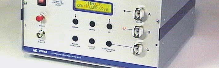
4 Power switch 2. LCD Display 3. Normal Air Pulse Outlet 4. Complimentary Air Pulse Outlet 5. Continuous Air Outlet 6. Start Button 7. External Start Command Input (Pedal switch) 8. Program Buttons 9. Activated Charcoal Filter Holder 10. Mains Power ( V; Hz) Receptacle 11. Stimulus Signal Output
5 , The Stimulus Air Controller is an autonomous apparatus designed to deliver controlled air flows for application in chemoreception research. Two independent air flows are created by means of miniature membrane pumps. The pumps are arranged in such a way that the vibrations, which are typical for this kind of pumps, are minimized. The output flow rates of the pumps can be adjusted. One of the outputs can be pulsed by means of an adjustable timer. The flow and timing control circuits are microprocessor controlled. The air is purified by an replaceable activated charcoal filter at the air inlet. INSTALLATION and OPERATION 1. Connect the power cord. Power range: V; Hz. 2. Connect the pedal switch. 3. Make a tube connection from the outlet of the continuous flow (5) to the mixing tube, which is directed to the antennal preparation. 4. Connect the stimulus source (Pasteur pipette) by means of a flexible tube to the NORMAL (A) pulse flow outlet (3). 5. Switch the unit on by activating the POWER switch (Nr.1) The LCD indicator should light up; if this is not the case check the fuse inside the power cord receptacle (10) at the rear of the box. 6. Adjust the continuous flow rate by pressing the pulse flow button and using the arrow buttons. Press the button again to return to standby mode. A moderate flow should be blown over the antennal preparation. The optimum flow rate (in the range of cm/s) is dependent on the diameter of the flow tube and is best found by trial and error with a fresh antennal preparation. Avoid vibration of the preparation, which might be induced by too high flow rates. 7. Adjust the flow rate of the pulse flow by pressing the pulse flow button and using the arrow buttons). The pulse flow can be measured from the B (complementary) outlet (4). This outlet delivers the adjusted flow continuously, but is interrupted during delivery of a pulse from the NORMAL (A) outlet (3). 8 Press the START button or the start pedal. An air pulse is delivered from the NORMAL (A) outlet, the flow from outlet B is interrupted, and the action is indicated by the LCD indicator. 9. Adjust the stimulus pulse duration by pressing the Pulse duration button and using the arrow buttons. Return to normal mode by pressing the Pulse duration button again. The most appropriate pulse duration in combination with a certain flow is best determined at the beginning of a recording session. Short pulses induce less adaptation in the antenna, but may elicit lower EAG responses. 10 Place a stimulus pipette and insert the tip of the pipette into the side hole of the mixing tube.
6 Continuous flow outlet Start pedal switch Flow meter Continuous flow measurement Complementary outlet to Stimulus to Preparation Pulse flow measurement
7 Antennal preparation Humidifier Mixing tube Start pedal switch Stimulus source Standard tube arrangement Antennal preparation Humidifier Mixing tube T-connector Stimulus source Arrangement for pulse flow compensation
8 V2.4 Initial display text: Embedded software version (V2.4) DOWN MENU UP Upper 3 buttons: Menu control and settings Arrow buttons: change menu settings To leave MENU: press one of 3 lower buttons Lower 3 buttons: Pulse duration and Flow adjustment (press one time to adjust - second time to return to normal) PULS << 1.0 Sec >> PULS # # # # # # # # # # # # DOWN MENU UP DOWN MENU UP DOWN MENU UP MENU Press MENU button to scroll through menu options V2.4 Initial display text: Embedded software version (V2.4) LCD BACKLIGHT << ON >> Display Backlight: ON - OFF LCD CONTRAST << 30 >> Display Contrast: 0-60 TRIG OUTPUT POL << NORMAL >> Trigger Output Polarity: Output signal (# 11 at rear panel): Normal (positive going) - Inverted (negative going) SOUND << ON >> Action Indicating BEEB sound: ON - OFF REPEAT << OFF >> Automatic Repeat: ON - OFF (Normally OFF) REPEAT TIME << 10 >> Repeat Interval time: s (when Repeat option is ON) REPEAT CYCLES << 5 >> Number of repeat cycles: (when Repeat option is ON) EXT. CONTROL << OFF >> Direct control: OFF (normal) - ON (control by external timing signal connected to Pedal switch receptacle (# 7 on front panel) TRIGGER DELAY OFF >> Trigger delay: OFF (0) or s. Delay between activation of START button and actual output air pulse. To leave the MENU mode press any of the 3 lower buttons ( after 10 s of no action the system leaves the menu automatically)
9 11 Press the start pedal. Watch the EAG signal on the display screen of the signal processing system (oscilloscope or PC program) and make any necessary adjustments. MEASUREMENT The flow rate delivered by the outputs can be easily measured by means of a suitable flow meter. To measure the flow of the output simply connect the flow meter temporarily to the associated tube. For accurate measurements it is recommended to measure the flow using the same tube as applied in the actual EAG set-up. The pulsed flow output can be measured from outlet B (4), which delivers the same flow rate as the A (3) output during activation. Measurement of the pulsed output in VOLUME per can be achieved by connecting a sensitive "soap film" flow meter (such as used for carrier gas flow measurement in gas chromatographs) to the outlet of the stimulus source Pasteur pipette. The displacement of the soap film during the selected pulse period can thus conveniently be gauged. The actual flow rate is not critical in general EAG experiments. For reasons of compatibility the continuous air flow is preferably reported as linear air speed (m/s) over the preparation, whereas the stimulus flow is best expressed in volume per time (ml/s). COMPENSATION During application of a stimulus the total air flow over the preparation is temporarily increased by the flow introduced from the stimulus pipette. Depending on the sensitivity of the preparation to mechanical stimulation this "pressure shock" may induce a significant response. This effect can be considerably reduced if the air flow from the B (4) output is combined with the air flow. During stimulation the flow from the B outlet is blocked, but delivered (via the odour source) from the A outlet at the same rate. ACTIVATED CHARCOAL REPLACEMENT The activated charcoal inlet filter is accessible from the rear of the instrument. Unscrew the cover and remove the filter cartridge. The cartridge can be replaced or be regenerated by heating in an inert atmosphere at elevated temperature during several hours. SIGNAL OUTPUT The stimulation pulse signal is available from the BNC connector (11) present at the rear panel of the instrument as a positive or negative going ( to be set in the Menu: Trig. Output Pol ) 12 V signal with the same duration as the stimulus pulse. This signal can be used to monitor the stimulus pulse on an oscilloscope, recorder or any other electronic device, and as a trigger signal to start signal acquisition.
10 STIMULU S CO NT RO L LER STIM ULU S CO NTRO LLER CO NT R OLL ER CO NTR OLLER Antennal preparation Continuous flow outlet Humidifier Mixing tube Stimulus source Start pedal switch Flow meter Start pedal switch Continuous flow measurement Standard tube arrangement Complementary outlet Antennal preparation to Stimulus Humidifier Mixing tube T-connector Stimulus source to Preparation Pulse flow measurement Arrangement for pulse flow compensation Power switch 2. LCD Display 3. Normal Air Pulse Outlet 4. Complimentary Air Pulse Outlet 5. Continuous Air Outlet 6. Start Button 7. External Start Command Input (Pedal switch) 8. Program Buttons 9. Activated Charcoal Filter Holder 10. Mains Power ( V; Hz) Receptacle 11. Stimulus Signal Output
11 V2.4 Initial display text: Embedded software version (V2.4) DOWN MENU UP Upper 3 buttons: Menu control and settings Arrow buttons: change menu settings To leave MENU: press one of 3 lower buttons Lower 3 buttons: Pulse duration and Flow adjustment (press one time to adjust - second time to return to normal) PULS << 1.0 Sec >> PULS # # # # # # # # # # # # DOWN MENU UP DOWN MENU UP DOWN MENU UP MENU Press MENU button to scroll through menu options V2.4 Initial display text: Embedded software version (V2.4) LCD BACKLIGHT << ON >> Display Backlight: ON - OFF LCD CONTRAST << 30 >> Display Contrast: 0-60 TRIG OUTPUT POL << NORMAL >> Trigger Output Polarity: Output signal (# 11 at rear panel): Normal (positive going) - Inverted (negative going) SOUND << ON >> Action Indicating BEEB sound: ON - OFF REPEAT << OFF >> Automatic Repeat: ON - OFF (Normally OFF) REPEAT TIME << 10 >> Repeat Interval time: s (when Repeat option is ON) REPEAT CYCLES << 5 >> Number of repeat cycles: (when Repeat option is ON) EXT. CONTROL << OFF >> Direct control: OFF (normal) - ON (control by external timing signal connected to Pedal switch receptacle (# 7 on front panel) TRIGGER DELAY OFF >> Trigger delay: OFF (0) or s. Delay between activation of START button and actual output air pulse. To leave the MENU mode press any of the 3 lower buttons ( after 10 s of no action the system leaves the menu automatically)
12 Ockenfels GmbH Stegener Strasse 17a Kirchzarten Germany
TASTEPROBE Type DTP-1. Pre-amplifier for recording from contact chemosensilla INSTRUCTIONS
 TASTEPROBE Type DTP-1 Pre-amplifier for recording from contact chemosensilla INSTRUCTIONS SYNTECH 2002 Hilversum, The Netherlands Reproduction of text and/or drawings is permitted for personal use. The
SPECIFICATION NO Model 207 Automatic GTAW Welding System
 1.0 Introduction The Model 207 is a completely self-contained Gas Tungsten Arc Welding (GTAW) System requiring only input power, inert gas and AMI Welding Head (or manual torch) for operation. Its small
SPECIFICATION NO NOTE
 NOTE The Model 207-1 is a special version of the standard M-207 Power Supply. It has been altered for a special applications requiring low current operation at high arc voltages in ambient and pressurized
Check our knowledge base at
 USER MANUAL Check our knowledge base at www.paralinx.net/support Copyright 2015 Paralinx LLC All Rights Reserved TABLE OF CONTENTS 1 Important Notice 10 LCD Screen 2 Safety Instructions 11 Indicators 3
WQ Series Water Quality Bench top Meters
 USER GUIDE WQ Series Water Quality Bench top Meters Model WQ500 ph, ORP and Temperature Model WQ510 ph, ORP, Conductivity, TDS, Salinity, & Temperature Model WQ530 ph, ORP, Conductivity, TDS, Salinity,
EN - English Washington Street Melrose, MA Phone Toll Free Revision 4 20/06/17
 - English... 1 Instruction Manual Vortex Mixer, Mini Fix Speed, VXMNFS Vortex Mixer, Mini Analog, VXMNAL Vortex Mixer, Mini Digital, VXMNDG Vortex Mixer, Mini Pulsing, VXMNPS 99 Washington Street Melrose,
Instruction Manual Fixed Speed Vortex Mixer Analog Vortex Mixer Digital Vortex Mixer Pulsing Vortex Mixer
 Instruction Manual Fixed Speed Vortex Mixer Analog Vortex Mixer Digital Vortex Mixer Pulsing Vortex Mixer Table of Contents Package Contents............ 1 Warranty............ 1 Installation............
Operating instructions Electronic preset counter Type series 717
 Operating instructions Electronic preset counter Type series 717 1. Description 5.98.3_gb 6-digit adding/subtracting counter with two presets Very bright 8mm high LED display Counting and preset range
WELDING CONTROL UNIT: TE 450 USER MANUAL
 j WELDING CONTROL UNIT: TE 450 USER MANUAL RELEASE SOFTWARE No. 1.50 DOCUMENT NUMBER: MAN 4097 EDITION: MARCH 1998 This page is left blank intentionally. 2 / 34 TABLE OF CONTENTS SUBJECTS PAGE WELDING
Digital Delay / Pulse Generator DG535 Digital delay and pulse generator (4-channel)
") Digital Delay / Pulse Generator Digital delay and pulse generator (4-channel) Digital Delay/Pulse Generator Four independent delay channels Two fully defined pulse channels 5 ps delay resolution 50 ps
Digital Delay / Pulse Generator Digital delay and pulse generator (4-channel) Digital Delay/Pulse Generator Four independent delay channels Two fully defined pulse channels 5 ps delay resolution 50 ps
Customer Responsibilities. Important Customer Information. Agilent InfinityLab LC Series Site Preparation Checklist
 Agilent Site Preparation InfinityLab Checklist LC Series Thank you for purchasing an Agilent instrument. To get you started and to assure a successful and timely installation, please refer to this specification
DCL9AW. User Manual. English
 DCL9AW User Manual English PRECAUTIONS Information for users applicable in European Union countries 1 Information for users applicable in United States of America 1 Installation 1 Power connection 1 Maintenance
FD Trinitron Colour Television
 R 4-205-569-32(1) FD Trinitron Television Instruction Manual GB KV-14LM1U 2000 by Sony Corporation NOTICE FOR CUSTOMERS IN THE UNITED KINGDOM A moulded plug complying with BS1363 is fitted to this equipment
MP212 Principles of Audio Technology II
 MP212 Principles of Audio Technology II Black Box Analysis Workstations Version 2.0, 11/20/06 revised JMC Copyright 2006 Berklee College of Music. All rights reserved. Acrobat Reader 6.0 or higher required
PQ-Box 100 Quick Start Instructions
 PQ-Box 100 Quick Start Instructions These instructions are provided for the purpose on providing a quick start to PQ-Box 100 installation and operation. Please refer to the user handbook for full details.
800 Displaying Series Flowmeter
 TECHNICAL PRODUCT INSTRUCTION SHEET 800 Displaying Series Flowmeter OVERVIEW The principle of operation is very simple. A jet of liquid is directed at a free running Pelton wheel turbine in a specially
SATRI AMPLIFIER AMP-51R. Owner s Manual
 SATRI AMPLIFIER AMP-51R Owner s Manual contents SAFETY INSTRUCTIONS 4 INTRODUCTION 6 OVERVIEW (FRONT PANEL) 8 OVERVIEW (REAR PANEL) 9 OVERVIEW (REMOTE CONTROL) 1 1 OPERATION 12 TROUBLESHOOTING 13 SPECIFICATION
Replacing the Tubes
 6-1-3. Replacing the Tubes The Tubes can be replaced for every color. The following procedure shows the example of replacing the Tube for Cyan. The procedure is the same for other colors. (1) Make sure
Digital Storage Oscilloscopes 2550 Series
 Data Sheet Digital Storage Oscilloscopes 2550 Series The 2550 series digital storage oscilloscopes provide high performance and value in 2-channel and 4-channel configurations. With bandwidth from 70 MHz
User Manual. TCU/RCU RF Head Control Units. TCU/RCU Analogue 11/6/
 11/6/2009 www.elber.com elber@elber.it TCU/RCU RF Head Control Units User Manual Elber s.r.l.- Via Pontevecchio, 42W Phone +39-0185.35.13.33 16042 Carasco (GE) Italy Fax +39-0185.35.13.00 1 Sommario 2
Experiment 9A: Magnetism/The Oscilloscope
 Experiment 9A: Magnetism/The Oscilloscope (This lab s "write up" is integrated into the answer sheet. You don't need to attach a separate one.) Part I: Magnetism and Coils A. Obtain a neodymium magnet
USER MANUAL. 27 Full HD Widescreen LED Monitor L27ADS
 USER MANUAL 27 Full HD Widescreen LED Monitor L27ADS TABLE OF CONTENTS 1 Getting Started 2 Control Panel/ Back Panel 3 On Screen Display 4 Technical Specs 5 Care & Maintenance 6 Troubleshooting 7 Safety
CP1 OAD. Owner s Manual. Stereo Control Preamplifier. Ultrafidelity
 OAD Ultrafidelity CP1 Stereo Control Preamplifier Owner s Manual Contents Section Page No. Introduction........................................................................ 1 Warnings.................................................................................
RIGOL. Data Sheet. DS1000B Series Digital Oscilloscopes DS1074B, DS1104B, DS1204B. Product Overview. Easy to Use Design. Applications.
 RIGOL Data Sheet Product Overview DS1000B series oscilloscopes are designed with four analog channels and 1 external trigger channel, which can capture multi-channel signal simultaneously and meet industrial
Oscilloscope Guide Tektronix TDS3034B & TDS3052B
 Tektronix TDS3034B & TDS3052B Version 2008-Jan-1 Dept. of Electrical & Computer Engineering Portland State University Copyright 2008 Portland State University 1 Basic Information This guide provides basic
SM02. High Definition Video Encoder and Pattern Generator. User Manual
 SM02 High Definition Video Encoder and Pattern Generator User Manual Revision 0.2 20 th May 2016 1 Contents Contents... 2 Tables... 2 Figures... 3 1. Introduction... 4 2. acvi Overview... 6 3. Connecting
KHT 1000C HV-Probe Calibrator. Instruction Manual
 KHT 1000C HV-Probe Calibrator Instruction Manual Copyright 2015 PMK GmbH All rights reserved. Information in this publication supersedes that in all previously published material. Specifications are subject
Preset counters, electronic
 The multifunction preset counters Codix 923 / 924 can be used universally. These preset pulse counters, tachometers or preset timers with up to 6 presets can solve a wide variety of control and monitoring
Features of the 745T-20C: Applications of the 745T-20C: Model 745T-20C 20 Channel Digital Delay Generator
 20 Channel Digital Delay Generator Features of the 745T-20C: 20 Independent delay channels - 100 ps resolution - 25 ps rms jitter - 10 second range Output pulse up to 6 V/50 Ω Independent trigger for every
LCD Thermometer / Clock S No. 1253
 Installation and Operating Manual LCD Thermometer / Clock S No. 1253 The 3 fold thermometer with crystal clock is purpose build for the mounting in caravans, boats and intervention vehicles. Please read
FAST MOBILITY PARTICLE SIZER SPECTROMETER MODEL 3091
 FAST MOBILITY PARTICLE SIZER SPECTROMETER MODEL 3091 MEASURES SIZE DISTRIBUTION AND NUMBER CONCENTRATION OF RAPIDLY CHANGING SUBMICROMETER AEROSOL PARTICLES IN REAL-TIME UNDERSTANDING, ACCELERATED IDEAL
STX Stairs lighting controller.
 Stairs lighting controller STX-1795 The STX-1795 controller serves for a dynamic control of the lighting of stairs. The lighting is switched on for consecutive steps, upwards or downwards, depending on
Quick Start. RSHS1000 Series Handheld Digital Oscilloscope
 Quick Start RSHS1000 Series Handheld Digital Oscilloscope General Safety Summary Carefully read the following safety precautions to avoid personal injury and prevent damage to the instrument or any products
Home Cinema Projector LPX-500
 LPX-5 NEW PRODUCT BULLETIN Home Cinema Projector LPX-5 LCD projector designed exclusively for home cinema use featuring 16:9 widescreen display capability, high contrast film-like picture quality, Yamaha
Basic Vortex Mixer Standard Vortex Mixer Advanced Vortex Mixer Pulsing Vortex Mixer
 Instruction Manual Manual Basic Vortex Mixer Standard Vortex Mixer Advanced Vortex Mixer Pulsing Vortex Mixer Table of Contents Package Contents............... 1 Warranty............... 1 Installation...............
S op o e p C on o t n rol o s L arni n n i g n g O bj b e j ctiv i e v s
 ET 150 Scope Controls Learning Objectives In this lesson you will: learn the location and function of oscilloscope controls. see block diagrams of analog and digital oscilloscopes. see how different input
COHERENCE ONE PREAMPLIFIER
 COHERENCE ONE PREAMPLIFIER OWNER S MANUAL TABLE OF CONTENTS Introduction Features Unpacking Instructions Installation Phono Cartridge Loading Basic Troubleshooting Technical Specifications Introduction
Technical description and user manual. Survey Meter SM 8 D. Sensortechnik und Elektronik Pockau GmbH. Siedlungsstraße 5-7 D Pockau-Lengefeld
 Technical description and user manual Survey Meter SM 8 D Sensortechnik und Elektronik Pockau GmbH Siedlungsstraße 5-7 D 09509 Pockau-Lengefeld www.step-sensor.de Germany STEP-SM8D BD-EN-20170619-2 - state
Control Unit CU 2.1 User Manual V6850A HPLC
 Control Unit CU 2.1 User Manual V6850A HPLC 3 Table of Contents Control Unit... 5 Control... 5 Start Screen... 6 Main Menu... 6 Programs and Links... 7 General Settings... 8 Choosing the Network... 8 Setting
Sensopress LCD Special English
 Sensopress LCD Special English edition 2-09/2004 - code 5878 1/16 Sensopress LCD with sensor Power Supply Voltage 117 V~ 50 60 Hz 230V~ 50 60 Hz Code TSL00X0100 TSL00Y0100 Consumption 5,5 VA Display LCD
Concise NFC Demo Guide using R&S Test Equipment Application Note
 Concise NFC Demo Guide using R&S Test Equipment Application Note Products: R&S SMBV100A R&S SMBV-K89 R&S FS-K112PC R&S RTO R&S RTO-K11 R&S CSNFC-B8 R&S FSL R&S FSV R&S FSW R&S ZVL This concise NFC Demo
Dissolve Control Programming : Projector/Dissolve Control Hook-Up
 Product Information Title: Operating Equipment: Dissolve Control Programming Projector/Dissolve Control Hook-up Sync Track Hook-up Converting Tapes to Digital Sync Signals Recording Signals 80 Vs 140 Slide
Simple all-in-one design style with front stereo speakers and natural ventilation system
 LMD-B170 17-inch cost-effective, lightweight basic grade Full HD LCD monitor for versatile use Overview Lightweight and slim Full HD (1920 x 1080) LMD-B Series monitor with an excellent cost-performance
Controller, Scheduler-Timer Model UCS-01. User Guide
 Model UCS-01 User Guide QUICK REFERENCE GUIDE Time Date IDLE SCREEN 03:50PM [RUN] 05/09/06 Tue Day of the Week Schedule Mode (change via 'Set Time') [OFF] = No Events Operate [RUN] = Run 'R' Events Operate
COMPOSITE VIDEO LUMINANCE METER MODEL VLM-40 LUMINANCE MODEL VLM-40 NTSC TECHNICAL INSTRUCTION MANUAL
 COMPOSITE VIDEO METER MODEL VLM- COMPOSITE VIDEO METER MODEL VLM- NTSC TECHNICAL INSTRUCTION MANUAL VLM- NTSC TECHNICAL INSTRUCTION MANUAL INTRODUCTION EASY-TO-USE VIDEO LEVEL METER... SIMULTANEOUS DISPLAY...
ECE 5765 Modern Communication Fall 2005, UMD Experiment 10: PRBS Messages, Eye Patterns & Noise Simulation using PRBS
 ECE 5765 Modern Communication Fall 2005, UMD Experiment 10: PRBS Messages, Eye Patterns & Noise Simulation using PRBS modules basic: SEQUENCE GENERATOR, TUNEABLE LPF, ADDER, BUFFER AMPLIFIER extra basic:
Signal Conditioners. Highlights. Battery powered. Line powered. Multi-purpose. Modular-style. Multi-channel. Charge & impedance converters
 Signal Conditioners Highlights Battery powered Line powered Multi-purpose Modular-style Multi-channel Charge & impedance converters Industrial charge amplifiers & sensor simulators PCB Piezotronics, Inc.
INSTRUCTION & OPERATION MANUAL. MODEL MMW-05 (5kW) MUROMACHI MICROWAVE FIXATION SYSTEM
 MUROMACHI MICROWAVE FIXATION SYSTEM") INSTRUCTION & OPERATION MANUAL MODEL MMW-05 (5kW) MUROMACHI MICROWAVE FIXATION SYSTEM MUROMACHI KIKAI CO., LTD. TOKYO PRECAUTIONS The Microwave Fixation System is developed to rapidly halt brain chemical
INSTRUCTION & OPERATION MANUAL MODEL MMW-05 (5kW) MUROMACHI MICROWAVE FIXATION SYSTEM MUROMACHI KIKAI CO., LTD. TOKYO PRECAUTIONS The Microwave Fixation System is developed to rapidly halt brain chemical
ModelV-LCD70-AFHD. Operating Instructions
 ModelV-LCD70-AFHD Operating Instructions 1 2 This page intentionally left blank Table of Contents Top and Front Panel Features...6 Rear Panel Features...7 Compatible Input Formats...8 MAIN MENU AND NAVIGATION...9
Electro Magnetic Compatibility (EMC) Warning. Important notes for users in the U.K. FCC declaration. Caution. Fuse
 Warning. Important notes for users in the U.K. FCC declaration. Caution. Fuse") Warning: to prevent fire or shock hazard, do not expose camera or monitor to rain or moisture. The lightning flash with arrowhead symbol, within a triangle, is intended to alert the user to the presence
Warning: to prevent fire or shock hazard, do not expose camera or monitor to rain or moisture. The lightning flash with arrowhead symbol, within a triangle, is intended to alert the user to the presence
Common Spatial Patterns 3 class BCI V Copyright 2012 g.tec medical engineering GmbH
 g.tec medical engineering GmbH Sierningstrasse 14, A-4521 Schiedlberg Austria - Europe Tel.: (43)-7251-22240-0 Fax: (43)-7251-22240-39 office@gtec.at, http://www.gtec.at Common Spatial Patterns 3 class
Chapter 9 Introduction to Sequential Logic
 Chapter 9 Introduction to Sequential Logic Chapter Objectives Upon successful completion of this chapter, you will be able to: Explain the difference between combinational and sequential circuits. Define
Advanced Test Equipment Rentals ATEC (2832)
") Established 1981 Advanced Test Equipment Rentals www.atecorp.com 800-404-ATEC (2832) This product is no longer carried in our catalog. AFG 2020 Characteristics Features Ordering Information Characteristics
Established 1981 Advanced Test Equipment Rentals www.atecorp.com 800-404-ATEC (2832) This product is no longer carried in our catalog. AFG 2020 Characteristics Features Ordering Information Characteristics
Burlington County College INSTRUCTION GUIDE. for the. Hewlett Packard. FUNCTION GENERATOR Model #33120A. and. Tektronix
 v1.2 Burlington County College INSTRUCTION GUIDE for the Hewlett Packard FUNCTION GENERATOR Model #33120A and Tektronix OSCILLOSCOPE Model #MSO2004B Summer 2014 Pg. 2 Scope-Gen Handout_pgs1-8_v1.2_SU14.doc
R&S RT-ZF20 Power Deskew Fixture User Manual
 R&S RT-ZF20 Power Deskew Fixture User Manual (B00X2) User Manual Test & Measurement 1800.0040.02 04 This manual describes the following R&S RT-ZF models: R&S RT-ZF20 (1800.0004.01) 2016 Rohde & Schwarz
OWNER S MANUAL MOTORIZED 7 WIDE TFT LCD COLOR MONITOR CNT-701
 OWNER S MANUAL PW MOTORIZED 7 WIDE TFT LCD COLOR MONITOR CNT-701 ANY CHANGES OR MODIFICATIONS IN CONSTRUCTION OF THIS UNIT DEVICE WHICH IS NOT APPROVED BY THE PARTY RESPONSIBLE FOR COMPLIACE COULD VOID
SmartCrystal Cinema Neo
 Model VPSP-11100 www.volfoni.com 1 SUMMARY SUMMARY... 2 I. PRODUCT OVERVIEW... 3 II. REQUIREMENTS... 3 III. SMARTCRYSTAL CINEMA NEO FEATURES... 5 A. General specifications... 5 B. Technical specifications...
Patchmaster. Elektronik. The Pulse generator. February 2013
 Patchmaster The Pulse generator Elektronik Telly Galiatsatos, BS 1987: Graduated at Queens College, NY Computer Science 1987-2007: Instrutech Corporation IT Engineering Support Software Engineer, Sales
Software Manual Control Panel for Professional Single Booster Units Models: MM3 BW3
 Software Manual Control Panel for Professional Single Booster Units Models: MM3 BW3 EN Software Manual.. 1-14 1 1. DESCRIPTION 3 2. DISPLAY LAYOUT 4 3. MODES 5 3.1 Power On 5 3.2 Standby 5 3.3 Power off
16-CH Color Full Duplex Multiplexer Instruction Manual
 16-CH Color Full Duplex Multiplexer Instruction Manual 707-V1.5(S) Index: 1. Safety Warning 3 2. Introduction 3 3. Features 4 4. Specification 5 5. Front Panel Keypad 6 6. Back Panel Connection 10 7. Menu
COLOUR TFT LCD MONITOR USER S MANUAL Model: C172
 COLOUR TFT LCD MONITOR USER S MANUAL Model: C172 The display comes with a three year on site warranty. To activate your warranty please register your display at http://www.edge10.com by clicking on the
Resolution. Linearity H' less than 4% HV regulation 3.5% Dimensions 346 x 340 x 431mm (wxhxd) Mass 16.7kg (including SOl: 17.7kg)
 Mass 16.7kg (including SOl: 17.7kg)") .High resolution The newly developed HR Trinitron~ CRT enables the PVM-20M4U/14M4U ro achieve the high resolution of 80OTV lines. The PVM -20M2U/14M2U provide a 60OTV line resolution, with a dark tint
.High resolution The newly developed HR Trinitron~ CRT enables the PVM-20M4U/14M4U ro achieve the high resolution of 80OTV lines. The PVM -20M2U/14M2U provide a 60OTV line resolution, with a dark tint
Color TFT LCD Monitor The Art of Surveillance
 Color TFT LCD Monitor The Art of Surveillance User Manual Table of contents Safety Information---------------------------------------------------- 1-3 Accessories----------------------------------------------------------------3
ScopeMeter 190 Series Specifications
 Seite 1 von 7 ScopeMeter 190 Series Specifications Product Home Features Specifications Models, Options & Accessories Oscilloscope Mode Meter Mode Recorder Mode General Specifications Oscilloscope Mode
Sprite TL Quick Start Guide
 Sprite TL Quick Start Guide with 115 VAC Power Cord and 4-Conductor Signal Cable Reference Manual Sprite TL Online and downloadable Product Manuals and Quick Start Guides are available at www.hydrosystemsco.com
21 Channel Light Show PWM LED Controller with Remote Control
 21 Channel Light Show PWM LED Controller with Remote Control Application: Managing dynamic illuminated advertising signs, spectacular light walls, podiums, etc. Managing groups LED and LED strips - from
Owner's Manual. Monitors. 61 cm (23.6") LCD/TFT Monitor LED Backlight GML-2231M ASP AG
 LCD/TFT Monitor LED Backlight GML-2231M ASP AG") Owner's Manual Monitors EN GML-2231M GML-2431M 54.6 cm (21.5") LCD/TFT Monitor LED Backlight 61 cm (23.6") LCD/TFT Monitor LED Backlight GML-2231M.129.1.28.01.2014 ASP AG Content: 1. Important Safety
Owner's Manual Monitors EN GML-2231M GML-2431M 54.6 cm (21.5") LCD/TFT Monitor LED Backlight 61 cm (23.6") LCD/TFT Monitor LED Backlight GML-2231M.129.1.28.01.2014 ASP AG Content: 1. Important Safety
User Manual Digital Stroboscope
 Page 15/04/14 V1.0 Table Of Contents 1. Features 3 2. Specifications 3 & 4 2-1 General Specification 3 & 4 2-2 Flash Tube Specification 4 3. Front Panel Description 5 3-1 Flash Tube 5 3-2 Display 5
GE CardioSoft (Version 6.01 or higher) Tango M2 Interface Notes
 Tango M2 Interface Notes") GE CardioSoft (Version 6.01 or higher) Tango M2 Interface Notes To setup Tango M2 with your CardioSoft (V6.01 or higher), simply follow the directions below. 1. Verify Correct RS-232 and ECG Trigger Cables
GE CardioSoft (Version 6.01 or higher) Tango M2 Interface Notes To setup Tango M2 with your CardioSoft (V6.01 or higher), simply follow the directions below. 1. Verify Correct RS-232 and ECG Trigger Cables
GFT Channel Digital Delay Generator
 Features 20 independent delay Channels 100 ps resolution 25 ps rms jitter 10 second range Output pulse up to 6 V/50 Ω Independent trigger for every channel Fours Triggers Three are repetitive from three
Delmar Reynolds CardioDirect 12-S with CardioCollect Interface Tango M2 Interface Notes
 Delmar Reynolds CardioDirect 12-S with CardioCollect Interface Tango M2 Interface Notes To setup Tango M2 with the CardioDirect stress system, simply follow the directions below. 1. Verify Correct RS-232
Overview. Know Your Oscilloscope. Front Panel. Rear Panel. Sharing Agilent s Resources with Engineering Educators
 Know Your Oscilloscope Overview Front Panel Sharing Agilent s Resources with Engineering Educators www.educatorscorner.com Horizontal (time) controls Run control Special purpose menus/controls Trigger
Data Pattern Generator DG2020A Data Sheet
 Data Pattern Generator DG2020A Data Sheet DG2000 Series Features & Benefits Data Rate to 200 Mb/s Data Pattern Depth 64 K/channel Speeds Characterization Multiple Output Channels Increases Flexibility
Operating Instructions (ed. 5.97) Electronic Preset Counter Type Series 904
 Electronic Preset Counter Type Series 904") Operating Instructions 3.96.3 (ed. 5.97) Electronic Preset Counter Type Series 904 1. Description 6 digit preset counter, 2 presets, add./subtr. bright 2-line LCD display with symbols for activated outputs
Operating Instructions 3.96.3 (ed. 5.97) Electronic Preset Counter Type Series 904 1. Description 6 digit preset counter, 2 presets, add./subtr. bright 2-line LCD display with symbols for activated outputs
USER MANUAL Full HD Widescreen LED Monitor L236VA
 USER MANUAL 23.6 Full HD Widescreen LED Monitor L236VA TABLE OF CONTENTS 1 Getting Started 2 Control Panel/ Back Panel 3 On Screen Display 4 Technical Specs 5 Care & Maintenance 6 Troubleshooting 7 Safety
MachineryMate 800 operating guide Handheld vibration meter
 MachineryMate 800 operating guide Handheld vibration meter Wilcoxon Sensing Technologies 20511 Seneca Meadows Parkway, Germantown MD 20876, USA Amphenol (Maryland), Inc d/b/a Wilcoxon Sensing Technologies
Schiller AT-10 plus Tango M2 Interface Notes
 Schiller AT-10 plus Tango M2 Interface Notes To setup Tango M2 with the AT-10 plus stress system, simply follow the directions below. 1. Verify Correct RS-232 and ECG Trigger Cables RS-232 Cable used to
Flow Switch. Flow Switch
 Flow Switch Flow Switch u Pressure - Electronic Pressure Switches - Mechanical Pressure Switches - Pressure Transducer u Valves & Regulators u Temperature u Level u Flow u Air Suspension Valves Barksdale
3214NXT. Service Manual. IMPORTANT: Fill in Pertinent Information on Page 3 for Future Reference
 3214NXT Service Manual IMPORTANT: Fill in Pertinent Information on Page 3 for Future Reference Table of Contents Job Specification Sheet 3 Timer Operation 4 System Operation in Service 6 Flow in a Four-Unit
Preset Counters. X e. X d 6.92 X. 0. IP khz Batch. LCD Preset Counters 1, 2, 4 or 6 Presets. Multifunction. Fast and user-friendly
 The Codix 923/924 can be used universally. As a preset pulse counter, tachometer or preset timer with up to 6 presets it is able to solve a very wide range of control and monitoring tasks in every application.
Dimming actuators GDA-4K KNX GDA-8K KNX
 Dimming actuators GDA-4K KNX GDA-8K KNX GDA-4K KNX 108394 GDA-8K KNX 108395 Updated: May-17 (Subject to changes) Page 1 of 67 Contents 1 FUNCTIONAL CHARACTERISTICS... 4 1.1 OPERATION... 5 2 TECHNICAL DATA...
TS2.8 Sub OWNER S MANUAL
 TS2.8 Sub OWNER S MANUAL TS2.8 Sub CONTENTS IMPORTANT SAFETY INSTRUCTIONS 03 WARNINGS 03 FUSE PROTECTION 04 WARNING: STRONG MAGNETIC FIELD 04 EMC / EMI 04 ECODESIGN STANDBY POWER CONSUMPTION 04 WARRANTY
USER MANUAL. 22" Class Slim HD Widescreen Monitor L215DS
 USER MANUAL 22" Class Slim HD Widescreen Monitor L215DS TABLE OF CONTENTS 1 Getting Started Package Includes Installation 2 Control Panel / Back Panel Control Panel Back Panel 3 On Screen Display 4 Technical
NS-3 RF Noise Source Operation Manual
 RF Noise Source Operation Manual Version 2.04 June 3, 2016 SPECIFICATIONS Frequency... Maximum output level... Output flatness... (at max output level) Impedance... Displayed level... Repeatability...
Modular Lube Lubrication Systems System Controls
 Model 84501 Program Timer Solid State Designed to control the lubrication cycle frequency of air-operated single-stroke pumps. Timer turns pump on/off at programmed intervals via a 3-way or 4-way air solenoid
CLR-101C CAMERA LINK REPEATER. User s Manual. Document # , Rev 1.0, 2/24/2013
 LINK REPEATER User s Manual Document # 200624, Rev 1.0, 2/24/2013 Vivid Engineering 159 Memorial Drive, Suite F Shrewsbury, MA 01545 Phone 508.842.0165 Fax 508.842.8930 www.vividengineering.com info@vividengineering.com
Cable Calibration Function for the 2400B/C and 2500A/B Series Microwave Signal Generators. Technical Brief
 Cable Calibration Function for the 2400B/C and 2500A/B Series Microwave Signal Generators Technical Brief Quickly and easily apply a level correction table to compensate for external losses or power variations
TV Synchronism Generation with PIC Microcontroller
 TV Synchronism Generation with PIC Microcontroller With the widespread conversion of the TV transmission and coding standards, from the early analog (NTSC, PAL, SECAM) systems to the modern digital formats
UNITY 2 TM. Version 1.0. February 2008
 UNITY 2 TM ULTRA 50:50 Operators Manual Version 1.0 February 2008 1. Loading tubes onto ULTRA 50:50...3 1.1. DiffLok analytical end caps for sample tubes...3 1.2. Capping tubes with DiffLok caps...3 1.3.
GFT Channel Slave Generator
 GFT1018 8 Channel Slave Generator Features 8 independent delay channels 1 ps time resolution < 100 ps rms jitter for optical triggered delays 1 second range Electrical or optical output Three trigger modes
2013, 2014 Hewlett-Packard Development Company, L.P.
 User Guide 2013, 2014 Hewlett-Packard Development Company, L.P. The only warranties for HP products and services are set forth in the express warranty statements accompanying such products and services.
G.R.A.S. Sound & Vibration
 Instruction Manual Single-channel Low-noise Measuring System consisting of: ½-inch Low-noise Level Microphone System Type 40HH and Power Module Type 12HF 40HH 12HF G.R.A.S. Sound & Vibration Skovlytoften
USER MANUAL. 27 Full HD Widescreen LED Monitor L270E
 USER MANUAL 27 Full HD Widescreen LED Monitor L270E TABLE OF CONTENTS 1 Getting Started 2 Control Panel/ Back Panel 3 On Screen Display 4 Technical Specs 5 Care & Maintenance 6 Troubleshooting 7 Safety
Owner's Manual. Monitors. 48 cm (19") LCD/TFT Monitor LED Backlight GML-1730M ASP AG
 LCD/TFT Monitor LED Backlight GML-1730M ASP AG") Owner's Manual Monitors EN GML-1730M GML-1930M GML-1931M 43 cm (17") LCD/TFT Monitor LED Backlight 48 cm (19") LCD/TFT Monitor LED Backlight 48 cm (19") LCD/TFT Monitor LED Backlight GML-1730M.23.1.10.01.2013
Owner's Manual Monitors EN GML-1730M GML-1930M GML-1931M 43 cm (17") LCD/TFT Monitor LED Backlight 48 cm (19") LCD/TFT Monitor LED Backlight 48 cm (19") LCD/TFT Monitor LED Backlight GML-1730M.23.1.10.01.2013
Broadcast LCD Displays
 Broadcast LCD Displays Penta Media Lab Broadcast-LCD with brilliance and quality The HD2line LCD display series by is a product developed and manufactured in Germany. It is ideally suited for broadcast
LCD VALUE SERIES (32 inches)
") LCD VALUE SERIES (32 inches) http://www.orionimages.com All contents of this document may change without prior notice, and actual product appearance may differ from that depicted herein 1. SAFETY INSTRUCTION
LCD VALUE SERIES (32 inches) http://www.orionimages.com All contents of this document may change without prior notice, and actual product appearance may differ from that depicted herein 1. SAFETY INSTRUCTION
VITEK VTM-TLM191 VTM-TLM240
 VTM-TLM191 VTM-TLM240 19 & 24 Professional LED Monitors with HDMI, VGA, and Looping BNC VITEK FEATURES 19 & 24 Wide Screen LED Display Panel HDMI, VGA, and Looping BNC Composite Video Inputs & Stereo Audio
4830A Accelerometer simulator Instruction manual. IM4830A, Revision E1
 4830A Accelerometer simulator Instruction manual IM4830A, Revision E1 IM4830, Page 2 The ENDEVCO Model 4830A is a battery operated instrument that is used to electronically simulate a variety of outputs
FRACTION COLLECTOR. Microcomputer Controlled CHF122SC
 FRACTION COLLECTOR Microcomputer Controlled CHF122SC From open column to HPLC liquid chromatography and general liquid samplings, the Super Fraction Collector, model CHF122SC has a wide range of uses.
VOD/DATA RECORDERS AND ACCESSORIES FOR ASSOCIATED APPLICATIONS PRODUCT LIST
 VOD/DATA RECORDERS AND ACCESSORIES FOR ASSOCIATED APPLICATIONS PRODUCT LIST MREL DOCUMENT #: PROD180102 THESE PRODUCTS AND PRICES ARE AVAILABLE TO PRE-SCREENED, PRE-APPROVED CUSTOMERS ONLY. PRICES ARE